WO2014069596A1 - リレー固定構造 - Google Patents
リレー固定構造 Download PDFInfo
- Publication number
- WO2014069596A1 WO2014069596A1 PCT/JP2013/079618 JP2013079618W WO2014069596A1 WO 2014069596 A1 WO2014069596 A1 WO 2014069596A1 JP 2013079618 W JP2013079618 W JP 2013079618W WO 2014069596 A1 WO2014069596 A1 WO 2014069596A1
- Authority
- WO
- WIPO (PCT)
- Prior art keywords
- relay
- rib
- housing
- locking
- cover
- Prior art date
- Legal status (The legal status is an assumption and is not a legal conclusion. Google has not performed a legal analysis and makes no representation as to the accuracy of the status listed.)
- Ceased
Links
Images



Classifications
-
- H—ELECTRICITY
- H01—ELECTRIC ELEMENTS
- H01H—ELECTRIC SWITCHES; RELAYS; SELECTORS; EMERGENCY PROTECTIVE DEVICES
- H01H45/00—Details of relays
- H01H45/02—Bases; Casings; Covers
- H01H45/04—Mounting complete relay or separate parts of relay on a base or inside a case
-
- H—ELECTRICITY
- H01—ELECTRIC ELEMENTS
- H01H—ELECTRIC SWITCHES; RELAYS; SELECTORS; EMERGENCY PROTECTIVE DEVICES
- H01H50/00—Details of electromagnetic relays
- H01H50/02—Bases; Casings; Covers
- H01H50/04—Mounting complete relay or separate parts of relay on a base or inside a case
- H01H50/047—Details concerning mounting a relays
- H01H50/048—Plug-in mounting or sockets
-
- H—ELECTRICITY
- H05—ELECTRIC TECHNIQUES NOT OTHERWISE PROVIDED FOR
- H05K—PRINTED CIRCUITS; CASINGS OR CONSTRUCTIONAL DETAILS OF ELECTRIC APPARATUS; MANUFACTURE OF ASSEMBLAGES OF ELECTRICAL COMPONENTS
- H05K7/00—Constructional details common to different types of electric apparatus
- H05K7/02—Arrangements of circuit components or wiring on supporting structure
- H05K7/026—Multiple connections subassemblies
-
- H—ELECTRICITY
- H01—ELECTRIC ELEMENTS
- H01H—ELECTRIC SWITCHES; RELAYS; SELECTORS; EMERGENCY PROTECTIVE DEVICES
- H01H2223/00—Casings
- H01H2223/044—Protecting cover
Definitions
- the present invention relates to a structure for fixing a relay to a housing.
- a relay is mounted to control connection between a power supply device and a load (an example of this relationship is a battery assembly and an electric motor).
- a power supply device for example, in an electric vehicle that travels using an electric motor or a hybrid vehicle that travels using both an engine and an electric motor, the relay supplies power to the electric motor via an inverter.
- the relay includes a main relay that turns on and off the output of the battery assembly supplied to the inverter.
- the main relay has a pair of relay terminals, one of the relay terminals is connected to the total positive electrode of the battery assembly through a circuit, and the other relay terminal is connected to the total of the battery assembly through the circuit. Connected to the negative electrode.
- the relay is one of constituent members of an electrical junction box (junction box) provided between the battery assembly and the electric motor, and is fixed to the housing of the electrical junction box (see Patent Document 1). .
- the housing is provided with a first restricting portion that restricts horizontal movement of the relay and a second restricting portion that restricts vertical movement.
- the relay is formed with a flange over the entire circumference of the lower part.
- the flange portion comes into contact with the locking piece formed in the second restricting portion, and presses the tip end portion of the locking piece to elastically deform the locking piece. And if the bottom face of a collar part contact
- the first restriction portion and the second restriction portion are provided in the housing, thereby restricting the movement of the relay in the horizontal direction and the vertical direction. It can be fixed to the housing.
- it is necessary to press-fit the relay against the second restricting portion and press-fit until the second restricting portion comes into contact with the first restricting portion while elastically deforming the second restricting portion.
- the assembling property is bad.
- the present invention has been made based on this, and the problem to be solved is to realize a relay fixing structure that can be easily assembled to a housing and can regulate movement in all directions, up, down, front, rear, left and right. There is.
- a relay fixing structure for fixing a relay for controlling opening and closing of an electric circuit to a housing, the bottom portion on which the relay is placed, and the outside of the relay
- a housing base having a wall portion standing upright from the bottom, surrounding the portion, a lid portion to be crowned by the relay, and suspended from the periphery of the lid portion toward the wall portion of the housing base
- a housing cover having an edge portion formed on the housing base, and a locking portion for locking the housing cover is provided on the housing base, and the housing cover is engaged with the locking portion.
- a stop portion, a rib portion that restricts movement of the relay, and an elastically deformable pressing portion that presses the relay are provided, and the rib portion includes a first rib portion that contacts the outer portion and the wall Department and this A plurality of the first rib portions and the second rib portions are formed over the entire circumference of the edge portion, and the pressing portion faces the relay.
- a relay fixing structure that is provided on the lid portion and is elastically deformed in a state where the locking portion and the locked portion are engaged to press the relay to the bottom portion.
- the relay is placed on the bottom of the housing base (base plate) and accommodated in the wall, and the relay is attached to the housing simply by assembling the cover covered by the relay to the housing base. Can be assembled easily. Further, in such an assembled state, it is possible to restrict the movement of the relay in all directions (that is, the horizontal direction and the vertical direction) of the housing in the up, down, front, back, left and right directions.
- the relay has a flange portion that is formed so as to protrude from the outer side portion located on the bottom side when placed on the bottom portion, over the entire circumference.
- the flange portion is provided with a relay fixing structure that interferes with the wall portion in a state where the relay is placed on the bottom portion.
- the relay has a configuration that has a flange portion that is formed over the entire circumference so as to protrude from the outer side portion on the mounting side to the bottom portion, and the relay portion has the relay at the bottom portion. What is necessary is just to make it interfere with the said wall part in the mounted state. Thereby, the movement of the relay in the horizontal direction can be effectively restricted in the vicinity where the collar portion is disposed on the relay, that is, on the bottom side when it is placed on the bottom portion.
- the relay can be easily assembled to the housing, and the movement of the relay in all directions of up, down, front, back, left and right can be restricted.
- FIG. 1 is an exploded perspective view of a relay fixing structure according to an embodiment of the present invention.
- FIG. 2 is a plan view showing a state before the relay is placed on the housing base (base plate).
- FIG. 3 is a plan view showing a state after the relay is placed on the housing base.
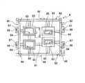
- FIG. 4 is an inner plan view of the housing cover.
- the relay fixing structure according to the present invention is a structure for fixing a relay for controlling opening and closing of an electric circuit to a housing.
- the relay is provided between a power source and a load connected to the power source, and controls electrical connection between the power source and the load.
- the power source include a power supply device (battery) that is mounted on an electric vehicle that runs using an electric motor, a hybrid vehicle that runs using an engine and an electric motor together, and supplies electric power to the electric motor.
- An example of the load is an electric motor supplied with power from such a power supply device.
- the combination of the power source and the load that the relay according to the present invention controls connection is not particularly limited to these combinations.
- Such a power supply device is arranged between a battery assembly in which a plurality of secondary batteries are connected in series, a pair of end plates that sandwich the battery assembly between each other, and the battery assembly and the electric motor.
- an electrical connection box junction box
- the electrical junction box can be configured to include a relay and a circuit for controlling on / off of the connection between the battery assembly and the electric motor.
- the relay may be held by an upper cover (corresponding to a housing described later), the circuit may be held by a lower cover, and the upper cover and the lower cover may be assembled to each other to constitute an electrical junction box.
- FIG. 1 is an exploded perspective view of a relay fixing structure according to an embodiment of the present invention
- FIG. 2 is a plan view showing a state before a relay is placed on a housing base described later
- FIG. FIG. 4 is a plan view showing the state after the relay is placed
- FIG. 1 is an exploded perspective view of a relay fixing structure according to an embodiment of the present invention
- FIG. 2 is a plan view showing a state before a relay is placed on a housing base described later
- FIG. FIG. 4 is a plan view showing the state after the relay is placed
- the relay 2 supplies power to an electric motor (not shown) via an inverter, and includes a main relay that turns on and off the output of a battery assembly (not shown) supplied to the inverter. It consists of The main relay has a pair of relay terminals, one of the relay terminals is connected to the total positive electrode of the battery assembly through a circuit, and the other relay terminal is connected to the total of the battery assembly through the circuit. Connected to the negative electrode. Thereby, the relay 2 controls the electrical connection between the battery assembly and the electric motor by turning on and off the electrical output from the battery assembly to the electric motor.
- FIG. 1 shows, as an example, the configuration of a relay 2 whose overall appearance is a substantially rectangular parallelepiped.
- the relay 2 is formed so as to protrude from the outer portion 21 located on the bottom portion 61 side (lower side in FIG. 1) when it is placed on the bottom portion 61 of a housing base (base plate) 6 described later.
- a collar 22 is provided. In addition, this collar part 22 becomes a mounting part of the relay with which the relay 2 contacts the bottom part 61.
- the relay fixing structure is a structure for fixing the relay 2 to the housing 4.
- the housing 4 includes a housing base (hereinafter referred to as a base plate) 6 and a housing cover (hereinafter simply referred to as a cover) 8.
- the base plate 6 and the cover 8 are both formed of an elastic material (for example, a resin material).
- the base plate 6 has a bottom portion 61 on which the relay 2 is placed, and a wall portion 62 erected from the bottom portion 61 that surrounds the outer side portion 21 of the relay 2.
- a terminal connection portion 63 having an insertion hole 64 into which a terminal of the relay 2 (for example, a male terminal (not shown)) is inserted is erected on the bottom portion 61.
- a terminal (for example, a female terminal) 65 connected to the terminal of the relay 2 is formed in the insertion hole 64.
- terminal connection parts 63 are erected from the bottom part 61 and four terminals 65 are formed in the insertion holes 64 of each terminal connection part 63.
- the number of terminal connection parts 63 is not particularly limited as long as it corresponds to the number of terminals of relay 2. Further, the terminal connection portion 63 (terminally, the terminal 65) can be arranged in any arrangement as long as it corresponds to the terminal arrangement of the relay 2.
- each of the wall portions 62 has an outer portion that is spaced a little larger than the projecting dimension of the flange portion 22 from the outer portion 21 when the relay 2 is placed on the bottom portion 61. 21. That is, the wall portion 62 is erected from the bottom portion 61 so as to be able to face the outer side portion 21 of the relay 2 with such an interval.
- the flange portion 22 is configured to be able to interfere with the wall portion 62 in a state where the relay 2 is placed on the bottom portion 61.
- the flange portion 22 interferes with the wall portion 62, so that the relay 2 accommodated in the wall portion 62 (hereinafter, the relay 2 is accommodated in the wall portion 62).
- the movement in the horizontal direction (front and rear, right and left directions along the bottom 61) in the positioning state can be restricted.
- the movement of the relay 2 in the horizontal direction is effectively restricted in the vicinity where the flange 22 is disposed on the relay 2, that is, on the bottom 61 side (lower side in FIG. 1) when placed on the bottom 61. can do.
- the wall portion 62 is appropriately provided with reinforcing ribs 66 so that the rigidity when the relay 2 is accommodated in the wall portion 62 is improved. Further, the height of the wall portion 62 from the bottom portion 61 is such that the relay 2 can be accommodated in the wall portion 62 and the locking portion 67 described later can engage the locked portion 84. Is set.
- the cover 8 has a lid portion 81 that is covered by the relay 2 and an edge portion 82 that is suspended from the periphery of the lid portion 81 toward the wall portion 62 of the base plate 6.
- the lid portion 81 has a substantially rectangular flat plate shape that is slightly larger than the upper end portion 23 of the relay 2, and is configured to be able to cover the entire upper end portion 23. Further, as shown in FIG. 4, the cover portion 81 is provided with reinforcing ribs 83 in a lattice shape, and the rigidity is improved when the lid 81 is crowned.
- the edge portion 82 is opposed to each wall portion 62 so as to be externally inserted into the wall portion 62 of the base plate 6 erected from the bottom portion 61 while surrounding the outer portion 21 of the relay 2 having a substantially rectangular parallelepiped shape. 81 is suspended from the periphery. Thereby, the cover 8 is covered with the relay 2 in a state where the upper end portion 23 of the relay 2 in the positioning state is covered with the lid portion 81 by extrapolating the edge portion 82 to the wall portion 62. Make a configuration.
- the base plate 6 is provided with a locking portion 67 that locks the cover 8, and the cover 8 is provided with a locked portion 84 that can engage the locking portion 67.
- locking part 67 is provided in the two wall parts 62 facing each other in the longitudinal direction (left-right direction in FIG. 3) of the bottom part 61, a total of four each. Yes.
- these locking portions 67 are disposed at symmetrical positions with the bottom portion 61 interposed therebetween.
- the locking portion 67 is formed so as to protrude outward from the vicinity of the upper edge portion of the wall portion 62.
- locking part 67 has the inclined surface 68 which inclines gradually from the inner side to the inner side, and the standing direction (upward direction in FIG. 1 and the front direction in FIG. 3 in other words. ) Is configured to taper as it goes to. That is, the locking portion 67 has a configuration corresponding to so-called return. As a result, when the locking portion 67 engages with the locked portion 84 described later, the locking portion 67 is smoothly guided along the inclined surface 68 to the locked portion 84, thereby easily engaging them. The engagement state can be maintained.
- the locked portion 84 is disposed on the outer side of the edge portion 82 at both ends in the longitudinal direction of the lid portion 81 (left and right direction in FIG. 4). Yes.
- the locked portion 84 is suspended so as to face the edge portion 82 with a predetermined interval.
- the locked portion 84 is provided so as to be flush with the lid portion 81 and beyond the edge portion 82 in the longitudinal direction, and then bent downward at a substantially right angle.
- a total of four openings 85 are provided in the locked portion 84, two at each bent portion, at symmetrical positions with the edge portion 82 in between.
- the position of the opening 85 of the locked portion 84 is made to correspond to the position of the locking portion 67 and the locked portion 84 is brought into contact with the inclined surface 68 of the locking portion 67.
- the cover 8 is moved by applying a pressing force to the base plate 6 side (lower side in FIG. 1) so that the locked portion 84 follows the inclined surface 68.
- the locked portion 84 receives a reaction force of the pressing force from the inclined surface 68 and is elastically deformed outward.
- the locked portion 84 is elastically deformed and deformed.
- the locked portion 84 is elastically bent and restored and deformed, the locking portion 67 is engaged with the lower edge 86 of the opening 85.
- the cover 8 and the base plate 6 can be assembled with each other.
- the cover 8 is provided with a rib portion 87 that restricts the movement of the relay 2.
- the rib portion 87 includes a first rib portion 87 a that contacts the outer side portion 21 of the relay 2 and a second rib portion 87 b that contacts the wall portion 62 of the base plate 6.
- a plurality of first rib portions 87 a and second rib portions 87 b are formed over the entire circumference of the edge portion 82.
- the rib part 87 (1st rib part 87a and 2nd rib part 87b) has controlled the movement to the horizontal direction (front-back left-right direction along the bottom part 61) of the relay 2 in a positioning state. .
- the first rib portion 87a is configured as a protruding piece that protrudes from the inner peripheral surface 82a of the edge portion 82 so as to be substantially orthogonal to the inner peripheral surface 82a.
- two projecting pieces are arranged symmetrically from the portion of the inner peripheral surface 82a facing the longitudinal direction of the cover 8 (left-right direction in the figure), and the longitudinal direction
- the configuration of the first rib portion 87a in which three projecting pieces are arranged symmetrically with respect to the intersecting direction (vertical direction in the figure) is shown. Note that the number of projecting pieces constituting the first rib portion 87a is not particularly limited as long as it can evenly contact the four outer portions 21 of the relay 2.
- the second rib portion 87b is configured as a protruding piece protruding from the outer peripheral surface 82b of the edge portion 82 so as to be substantially orthogonal to the outer peripheral surface 82b.
- two projecting pieces are arranged symmetrically from the portion of the outer peripheral surface 82 b facing the longitudinal direction of the cover 8 (left-right direction in the figure), and intersect with the longitudinal direction.
- the configuration of the second rib portion 87b in which two protruding pieces are arranged symmetrically with respect to each other in the direction (vertical direction in the figure) facing each other is shown. Note that the number of projecting pieces constituting the second rib portion 87b is not particularly limited as long as it can evenly abut against the four wall portions 62 facing the four outer portions 21 of the relay 2.
- first rib portion 87a and the second rib portion 87b are substantially staggered (staggered) so as to be disposed between the two rib portions 87 on the opposite sides with the edge portion 82 interposed therebetween. It has a protruding configuration.
- the first rib portion 87 a and the second rib portion 87 a and the second rib portion 82 a are disposed at the edge portions 82 (inner peripheral surface 82 a and outer peripheral surface 82 b) facing the longitudinal direction of the cover 8.
- the rib portions 87b are not configured to protrude alternately (staggered) across the edge portion 82.
- a configuration in which these are alternately arranged, that is, alternately projected may be employed.
- the locking portion 67 engages with the locked portion 84 and the cover 8 and the base plate 6 are locked with each other.
- the first rib portion 87 a contacts the outer portion 21 of the relay 2
- the second rib portion 87 b contacts the wall portion 62 of the base plate 6. Therefore, the protruding length from the inner peripheral surface 82a and the outer peripheral surface 82b of the edge portion 82 of the first rib portion 87a and the second rib portion 87b is the first rib protruding in the opposite direction across the edge portion 82.
- the distance from the projecting end of the portion 87a to the projecting end of the second rib portion 87b is the distance between the wall portion 62 and the outer portion 21 of the relay 2 (in other words, the projection of the flange portion 22 of the relay 2).
- (Dimension) may be set so as to be substantially the same size.
- the edge portion 82 in the positioning state of the relay 2. Is positioned approximately in the middle of the facing distance between the wall 62 and the outer portion 21 of the relay 2.
- the first rib portion 87 a can come into contact with the outer portion 21 of the relay 2, and the second rib portion 87 b can be attached to the base plate 6. It can abut against the wall 62.
- the movement of the relay 2 in the horizontal direction front and rear, right and left directions along the bottom 61
- the movement of the relay 2 in the horizontal direction can be effectively restricted on the upper end portion 23 side where the cover 8 is crowned.
- the cover 8 is provided with an elastically deformable pressing portion 88 that presses the relay 2.
- the pressing portion 88 is provided on the lid portion 81 so as to face the upper end portion 23 of the relay 2, and elastically deforms in a state where the locking portion 67 and the locked portion 84 are engaged to press the relay 2 to the bottom portion 61. . Accordingly, the pressing portion 88 restricts the movement of the relay 2 in the positioning state in the vertical direction (vertical direction with respect to the bottom portion 61).
- two pressing portions 88 are provided in a pair at a substantially central portion of the lid portion 81.
- the pressing portion 88 is in contact with the upper end portion 23 of the relay 2 in the positioning state, and can press the relay 2 against the bottom portion 61 evenly.
- the pair of pressing portions 88 has a base end portion 88a that is a continuous portion with the lid portion 81, and extends outward from the base end portion 88a in the longitudinal direction of the lid portion 81 (the left-right direction in FIG. 4).
- the plate-shaped portion 88b is configured to be elastically deformable with respect to the base end portion 88a. In the configuration shown in FIG.
- the plate-like portion 88 b is elastically bent in the vertical direction with respect to the base end portion 88 a continuous with the lid portion 81.
- the structure is deformable. That is, the pair of plate-like portions 88b gradually incline toward the upper end portion 23 of the relay 2 in the positioning state and protrude from the base end portion 88a while being separated from each other (in other words, gradually from the inside to the outside).
- the pressing portion 88 is configured so as to be inclined and spread. Thus, when a pressing force in the vertical direction acts on the plate-like portion 88b, the plate-like portion 88b can be elastically deformed against the pressing force.
- FIG. 4 shows an example of the configuration of the pressing portion 88 in which the plate-like portion 88b has a substantially trapezoidal shape and the long side portion is the base end portion 88a. It is also possible to make the plate-like portion into a substantially semicircular shape or a substantially semielliptical shape.
- a notch may be formed along the periphery of the plate-like portion, and the diameter portion, the long diameter portion, or the short diameter portion of the plate-like portion may be continuous with the lid portion 81 as a base end portion.
- a plate-like portion is extended from the base end portion toward the inside in the longitudinal direction of the lid portion 81 (left and right direction in FIG. 4), and the plate-like portion is elastically bent with respect to the base end portion. It can also be configured to be deformable.
- the pair of plate-like portions gradually incline toward the upper end portion 23 of the relay 2 in the positioning state and protrude from the base end portion while approaching each other (in other words, from the outside to the inside). What is necessary is just to comprise a press part so that it may incline and narrow gradually.
- the cover 8 when the cover 8 and the base plate 6 are assembled to each other, the cover 8 is placed so that the locked portion 84 is along the inclined surface 68 while the locked portion 84 is in contact with the inclined surface 68 of the locking portion 67.
- the plate-like portion 88b of the pressing portion 88 comes into contact with the upper end portion 23 of the relay 2 in the positioning state. If the cover 8 is further moved until the locking portion 67 engages with the locked portion 84 as it is, the plate-shaped portion 88b receives the pressing force and faces upward in the vertical direction (in other words, the upper end of the relay 2).
- the relay 2 is mounted on the base plate 6 only by placing the relay 2 in the positioning state and attaching the cover 8 covered by the relay 2 to the base plate 6.
- the movement of the relay 2 in the horizontal direction (front / rear / left / right direction along the bottom 61) on the side of the upper end 23 where the cover 8 is crowned is changed to the rib 87 (first The first rib portion 87a and the second rib portion 87b) can be effectively regulated.
- the pressing force of the pressing portion 88 acting on the upper end portion 23 (returning force due to elastic bending return deformation)
- in the vertical direction of the relay 2 (vertical direction with respect to the bottom portion 61) Can be effectively regulated.
- a relay fixing structure for fixing the relay (2) for controlling opening and closing of the electric circuit to the housing (6) A housing base (6) having a bottom portion (61) on which the relay is placed, and a wall portion (62) erected from the bottom portion, surrounding the outer portion (21) of the relay; A housing cover having a lid portion (81) to be crowned by the relay, and an edge portion (82) suspended from the periphery of the lid portion toward the wall portion of the housing base, The housing base is provided with a locking portion (67) for locking the housing cover, The housing cover includes a locked portion (84) that can be engaged with the locking portion, a rib portion (87) that restricts movement of the relay, and an elastically deformable pressing portion that presses the relay ( 88) and The rib portion includes a first rib portion (87a) that comes into contact with the outer portion and a second rib portion (87b) that comes into contact with the wall portion, and the first rib portion and the second rib portion.
- Each of the rib portions is formed in plural over the entire circumference of the edge portion
- the pressing portion is provided on the lid portion so as to face the relay, and elastically deforms in a state where the locking portion and the locked portion are engaged to press the relay to the bottom portion.
- Relay fixing structure. [2]
- the relay has a flange portion (22) formed so as to protrude over the entire circumference from the outer portion located on the bottom portion side when placed on the bottom portion, The relay fixing structure according to [1], wherein the flange portion interferes with the wall portion in a state where the relay is placed on the bottom portion.
- the relay can be easily assembled to the housing, and the movement of the relay in all directions of up, down, front, back, left and right can be restricted.
- the present invention exhibiting this effect is useful in the field of a structure for fixing a relay to a housing.
Landscapes
- Physics & Mathematics (AREA)
- Electromagnetism (AREA)
- Engineering & Computer Science (AREA)
- Microelectronics & Electronic Packaging (AREA)
- Connection Or Junction Boxes (AREA)
- Casings For Electric Apparatus (AREA)
- Mounting Components In General For Electric Apparatus (AREA)
Abstract
Description
前記リレーが載置される底部(61)と、前記リレーの外側部(21)を包囲する、前記底部から立設された壁部(62)とを有するハウジングベース(6)と、
前記リレーに被冠される蓋部(81)と、前記ハウジングベースの前記壁部へ向けて前記蓋部の周縁から垂設された縁部(82)とを有するハウジングカバーと
を備え、
前記ハウジングベースには、前記ハウジングカバーを係止する係止部(67)が設けられ、
前記ハウジングカバーには、前記係止部と係合可能な被係止部(84)と、前記リレーの移動を規制するリブ部(87)と、前記リレーを押圧する弾性変形可能な押圧部(88)とが設けられ、
前記リブ部は、前記外側部と当接する第1のリブ部(87a)と前記壁部と当接する第2のリブ部(87b)とを有し、前記第1のリブ部及び前記第2のリブ部それぞれは、前記縁部の全周に亘って複数形成され、
前記押圧部は、前記リレーと対向するよう前記蓋部に設けられ、前記係止部と前記被係止部が係合した状態で弾性変形して前記リレーを前記底部へ押圧する
リレー固定構造。
[2] 前記リレーは、前記底部へ載置された際の該底部側に位置する前記外側部から全周に亘って突出して形成された鍔部(22)を有し、
前記鍔部は、前記リレーが前記底部に載置された状態で前記壁部と干渉する
上記[1]に記載のリレー固定構造。
6 ハウジングベース(ベースプレート)
8 ハウジングカバー(カバー)
21 外側部
61 底部
62 壁部
67 係止部
81 蓋部
82 縁部
84 被係止部
87 リブ部
87a 第1のリブ部
87b 第2のリブ部
88 押圧部
Claims (2)
- 電気回路の開閉を制御するリレーをハウジングに固定するためのリレー固定構造であって、
前記リレーが載置される底部と、前記リレーの外側部を包囲する、前記底部から立設された壁部とを有するハウジングベースと、
前記リレーに被冠される蓋部と、前記ハウジングベースの前記壁部へ向けて前記蓋部の周縁から垂設された縁部とを有するハウジングカバーと
を備え、
前記ハウジングベースには、前記ハウジングカバーを係止する係止部が設けられ、
前記ハウジングカバーには、前記係止部と係合可能な被係止部と、前記リレーの移動を規制するリブ部と、前記リレーを押圧する弾性変形可能な押圧部とが設けられ、
前記リブ部は、前記外側部と当接する第1のリブ部と前記壁部と当接する第2のリブ部とを有し、前記第1のリブ部及び前記第2のリブ部それぞれは、前記縁部の全周に亘って複数形成され、
前記押圧部は、前記リレーと対向するよう前記蓋部に設けられ、前記係止部と前記被係止部が係合した状態で弾性変形して前記リレーを前記底部へ押圧する
リレー固定構造。 - 前記リレーは、前記底部へ載置された際の該底部側に位置する前記外側部から全周に亘って突出して形成された鍔部を有し、
前記鍔部は、前記リレーが前記底部に載置された状態で前記壁部と干渉する
請求項1に記載のリレー固定構造。
Priority Applications (3)
| Application Number | Priority Date | Filing Date | Title |
|---|---|---|---|
| CN201380057053.0A CN104782242A (zh) | 2012-11-01 | 2013-10-31 | 继电器固定结构 |
| DE112013005250.4T DE112013005250T8 (de) | 2012-11-01 | 2013-10-31 | Relaisfixierungsaufbau |
| US14/435,787 US9318287B2 (en) | 2012-11-01 | 2013-10-31 | Relay fixing structure |
Applications Claiming Priority (2)
| Application Number | Priority Date | Filing Date | Title |
|---|---|---|---|
| JP2012-242228 | 2012-11-01 | ||
| JP2012242228A JP6087110B2 (ja) | 2012-11-01 | 2012-11-01 | リレー固定構造 |
Publications (1)
| Publication Number | Publication Date |
|---|---|
| WO2014069596A1 true WO2014069596A1 (ja) | 2014-05-08 |
Family
ID=50627493
Family Applications (1)
| Application Number | Title | Priority Date | Filing Date |
|---|---|---|---|
| PCT/JP2013/079618 Ceased WO2014069596A1 (ja) | 2012-11-01 | 2013-10-31 | リレー固定構造 |
Country Status (5)
| Country | Link |
|---|---|
| US (1) | US9318287B2 (ja) |
| JP (1) | JP6087110B2 (ja) |
| CN (1) | CN104782242A (ja) |
| DE (1) | DE112013005250T8 (ja) |
| WO (1) | WO2014069596A1 (ja) |
Families Citing this family (6)
| Publication number | Priority date | Publication date | Assignee | Title |
|---|---|---|---|---|
| JP6441137B2 (ja) * | 2015-03-19 | 2018-12-19 | 矢崎総業株式会社 | 電気接続箱及びワイヤハーネス |
| US10604011B2 (en) | 2015-10-13 | 2020-03-31 | Consumer Safety Technology, Llc | Networked intoxication vehicle immobilization |
| JP6622932B1 (ja) * | 2019-01-31 | 2019-12-18 | マレリ株式会社 | リレー保持構造 |
| CN111558774A (zh) * | 2020-07-20 | 2020-08-21 | 昆山联滔电子有限公司 | 一种继电器焊接装置及焊接方法 |
| KR20230025101A (ko) | 2021-08-13 | 2023-02-21 | 한국단자공업 주식회사 | 전장부품 장착장치 |
| US12311759B1 (en) | 2022-02-02 | 2025-05-27 | Consumer Safety Technology, Llc | Wireless vehicle interface for immobilization system |
Citations (4)
| Publication number | Priority date | Publication date | Assignee | Title |
|---|---|---|---|---|
| JPH0443331U (ja) * | 1990-08-09 | 1992-04-13 | ||
| JP2002354631A (ja) * | 2001-05-23 | 2002-12-06 | Yazaki Corp | 電気部品の装着構造 |
| JP2004080966A (ja) * | 2002-08-21 | 2004-03-11 | Sumitomo Wiring Syst Ltd | 電気接続箱 |
| JP2005086865A (ja) * | 2003-09-05 | 2005-03-31 | Yazaki Corp | カセットリレーブロックの組付構造 |
Family Cites Families (8)
| Publication number | Priority date | Publication date | Assignee | Title |
|---|---|---|---|---|
| JP2840387B2 (ja) * | 1990-06-11 | 1998-12-24 | 株式会社リコー | 光信号処理装置 |
| JP3697961B2 (ja) * | 1999-08-02 | 2005-09-21 | 住友電装株式会社 | 電気接続箱 |
| JP3708028B2 (ja) * | 2001-05-30 | 2005-10-19 | シャープ株式会社 | デジタル放送受信装置 |
| JP4934332B2 (ja) | 2005-03-11 | 2012-05-16 | 古河電気工業株式会社 | 電気接続箱 |
| JP2007123314A (ja) * | 2005-10-25 | 2007-05-17 | Yazaki Corp | リレーモジュール及び電装ユニット |
| JP4605112B2 (ja) * | 2006-07-18 | 2011-01-05 | 住友電装株式会社 | 電気接続箱 |
| JP4356741B2 (ja) * | 2006-12-20 | 2009-11-04 | 住友電装株式会社 | 電気接続箱 |
| CN202512894U (zh) * | 2012-04-18 | 2012-10-31 | 纬创资通股份有限公司 | 壳体装置及壳体装置与储存装置的组件 |
-
2012
- 2012-11-01 JP JP2012242228A patent/JP6087110B2/ja active Active
-
2013
- 2013-10-31 CN CN201380057053.0A patent/CN104782242A/zh active Pending
- 2013-10-31 WO PCT/JP2013/079618 patent/WO2014069596A1/ja not_active Ceased
- 2013-10-31 US US14/435,787 patent/US9318287B2/en active Active
- 2013-10-31 DE DE112013005250.4T patent/DE112013005250T8/de not_active Expired - Fee Related
Patent Citations (4)
| Publication number | Priority date | Publication date | Assignee | Title |
|---|---|---|---|---|
| JPH0443331U (ja) * | 1990-08-09 | 1992-04-13 | ||
| JP2002354631A (ja) * | 2001-05-23 | 2002-12-06 | Yazaki Corp | 電気部品の装着構造 |
| JP2004080966A (ja) * | 2002-08-21 | 2004-03-11 | Sumitomo Wiring Syst Ltd | 電気接続箱 |
| JP2005086865A (ja) * | 2003-09-05 | 2005-03-31 | Yazaki Corp | カセットリレーブロックの組付構造 |
Also Published As
| Publication number | Publication date |
|---|---|
| US20150248980A1 (en) | 2015-09-03 |
| JP2014093377A (ja) | 2014-05-19 |
| DE112013005250T8 (de) | 2015-11-12 |
| CN104782242A (zh) | 2015-07-15 |
| US9318287B2 (en) | 2016-04-19 |
| JP6087110B2 (ja) | 2017-03-01 |
| DE112013005250T5 (de) | 2015-10-08 |
Similar Documents
| Publication | Publication Date | Title |
|---|---|---|
| JP6087110B2 (ja) | リレー固定構造 | |
| JP6475139B2 (ja) | 電池間接続装置及び電池間接続装置組立体 | |
| JP5876510B2 (ja) | 電気コネクタ及びコネクタシステム | |
| JP6160898B2 (ja) | 蓄電装置 | |
| JP5931376B2 (ja) | 組電池およびその製造方法 | |
| JP6352237B2 (ja) | 係合構造、電子部品モジュール、および電気接続箱 | |
| WO2020022273A1 (ja) | 電池ユニット | |
| KR20120080189A (ko) | 퓨즈 유닛 | |
| JP7028106B2 (ja) | 電池配線モジュール | |
| JP2020035610A (ja) | 電池配線モジュール | |
| JP7552412B2 (ja) | 電気接続箱 | |
| JP2014220067A (ja) | バスバモジュール及び電源装置 | |
| JP7107100B2 (ja) | 電池配線モジュール | |
| JP2014203694A (ja) | コネクタ | |
| CN108807737A (zh) | 电池配线模组 | |
| US12453020B2 (en) | Electronic control device case | |
| WO2021131861A1 (ja) | 電池配線モジュール | |
| WO2022172758A1 (ja) | 電気接続箱 | |
| JP6243305B2 (ja) | 電子部品の組付構造 | |
| CN222839946U (zh) | 用于bms控制器壳体的卡扣结构和bms控制器壳体 | |
| JP7226515B2 (ja) | 電池配線モジュール | |
| JP6023560B2 (ja) | 電線用保持部材への固定部材の保持構造 | |
| JP2026068286A (ja) | バスバ保護構造 | |
| JP2026067200A (ja) | バスバ保護構造 | |
| JP2021111484A (ja) | 電池配線モジュール |
Legal Events
| Date | Code | Title | Description |
|---|---|---|---|
| 121 | Ep: the epo has been informed by wipo that ep was designated in this application |
Ref document number: 13851006 Country of ref document: EP Kind code of ref document: A1 |
|
| WWE | Wipo information: entry into national phase |
Ref document number: 14435787 Country of ref document: US |
|
| WWE | Wipo information: entry into national phase |
Ref document number: 1120130052504 Country of ref document: DE Ref document number: 112013005250 Country of ref document: DE |
|
| 122 | Ep: pct application non-entry in european phase |
Ref document number: 13851006 Country of ref document: EP Kind code of ref document: A1 |