WO2014069237A1 - 架空線用テンションバランサ - Google Patents
架空線用テンションバランサ Download PDFInfo
- Publication number
- WO2014069237A1 WO2014069237A1 PCT/JP2013/078082 JP2013078082W WO2014069237A1 WO 2014069237 A1 WO2014069237 A1 WO 2014069237A1 JP 2013078082 W JP2013078082 W JP 2013078082W WO 2014069237 A1 WO2014069237 A1 WO 2014069237A1
- Authority
- WO
- WIPO (PCT)
- Prior art keywords
- link
- overhead wire
- tension
- link arm
- output shaft
- Prior art date
- Legal status (The legal status is an assumption and is not a legal conclusion. Google has not performed a legal analysis and makes no representation as to the accuracy of the status listed.)
- Ceased
Links
Images



Classifications
-
- H—ELECTRICITY
- H02—GENERATION; CONVERSION OR DISTRIBUTION OF ELECTRIC POWER
- H02G—INSTALLATION OF ELECTRIC CABLES OR LINES, OR OF COMBINED OPTICAL AND ELECTRIC CABLES OR LINES
- H02G7/00—Overhead installations of electric lines or cables
- H02G7/02—Devices for adjusting or maintaining mechanical tension, e.g. take-up device
-
- B—PERFORMING OPERATIONS; TRANSPORTING
- B60—VEHICLES IN GENERAL
- B60M—POWER SUPPLY LINES, AND DEVICES ALONG RAILS, FOR ELECTRICALLY- PROPELLED VEHICLES
- B60M1/00—Power supply lines for contact with collector on vehicle
- B60M1/12—Trolley lines; Accessories therefor
- B60M1/26—Compensation means for variation in length
Definitions
- the present invention relates to an overhead wire tension balancer that applies tension to an overhead wire.
- Patent Document 1 discloses a structure in which a spring and a link mechanism are combined as an overhead wire tension balancer.
- the spring expands and contracts by the rotation of the link mechanism, and tension generated from the spring is applied to the overhead wire via the link mechanism.
- an object of the present invention is to provide a structure that does not cause interference between the tension generating means and the link mechanism in the overhead wire tension balancer.
- the invention according to claim 1 is an output shaft connected to the overhead wire, a tension generating means for generating a tension applied to the overhead wire when the output shaft is pulled by the overhead wire, and the output shaft.
- the overhead wire tension balancer is characterized in that the tension generating means can be positioned between the first link arm portions.
- the tension generating means can be positioned between the pair of first link arm portions constituting the link mechanism.
- the pair of rotating first link arms and the tension generating means can be in a positional relationship. Therefore, it is possible to obtain a structure in which interference between the tension generating means and the link mechanism does not occur while pursuing space saving.
- the link mechanism includes the pair of first link arms as viewed from the direction of the axis around which the pair of first link arm portions rotate.
- a first action point that applies tension to the overhead wire, and a position that overlaps the pair of first link arm parts and that is away from the first action point, and the output shaft Is located on a line extending in a direction different from the second action point to which the first action point is connected and the line connecting the first action point and the second action point, and serves as a rotation center of the link mechanism And a position.
- the pair of first link arm portions rotate around the rotation center position.
- the second operating point pulls the output shaft away from the tension generating means, and a tension is generated that pulls the overhead wire.
- the invention according to claim 3 is the invention according to claim 2, wherein the link mechanism is coupled to the pair of first link arm portions, the pair of first link arm portions, and the pair of first link arm portions.
- a second link arm portion extending in a direction different from the extending direction of the first link arm portion, the second action point is located at the coupled position, and the second link arm portion
- the rotation center position is located at a position away from the second action point.
- the first link arm part and the second link arm part may be directly coupled or may be coupled via another member.
- the tension generating means has a longitudinal shape, the output shaft is pulled out from one end of the tension generating means, and the tension generation The means is characterized in that it can rotate around the other end.
- the link mechanism is rotated by being pulled by the overhead wire, and the output shaft is pulled out from the tension generating means while the tension generating means is also rotated accordingly.
- the invention according to claim 5 is the invention according to claim 3 or 4, wherein the link mechanism has a plate-like member including the first link arm part and the second link arm part.
- the link mechanism of the present invention is of course constituted by a longitudinal link arm, but can also be constituted by a plate-like member. In this case, the link mechanism can be grasped as a structure in which the link arm is included in the plate-like member.
- the member that rotatably supports the tension generating means and the member that rotatably supports the link mechanism are integrated. It has an integral member. According to the sixth aspect of the present invention, it becomes easy to set the tension generated by the tension generating means to an intended value (or an intended range).
- a structure is provided in which interference between the tension generating means and the link mechanism does not occur.
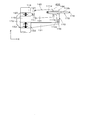
- They are a top view (A), a side view (B), and a side partial perspective view (C) of the embodiment. They are a top view (A), a side view (B), and a side partial perspective view (C) of the embodiment. They are a top view (A), a side view (B), and a side partial perspective view (C) of the embodiment. It is a perspective view of the link member in an embodiment. It is the top view (A) and side view (B) of embodiment. It is side view (A) and (B) of an embodiment. It is a side view of an embodiment. It is a perspective view which shows the link member of another example.
- First embodiment (structure) 1 to 3 show an overhead wire tension balancer 100.
- FIG. 1 shows a state in which no tension is applied from the overhead wire, or a state in which the tension is weak even if the overhead wire is applied and the output shaft is not pulled out. Then, the overhead wire is slightly pulled from the state of FIG. 1 in the right direction of the drawing, and the state where the spring is slightly extended is shown in FIG. 2, and further, the overhead wire is pulled slightly from the state of FIG. Further, the state in which the spring is slightly extended is shown in FIG.
- the overhead wire tension balancer 100 includes a coil spring assembly 140.
- the coil spring assembly 140 is a tension generating means using a coil spring.
- the coil spring is housed inside the cylindrical member, and when the output shaft is pulled out, the coil spring is compressed, and the output shaft is pulled back by the repulsive force. It has the function to generate the force to do.
- the coil spring assembly 140 rotates during operation as described later, and the tilt changes slightly, but is arranged in a substantially horizontal state. Note that the rotation in this specification means rotation in the plane of FIGS. 1B and 1C, that is, in the ZX plane of the drawing. This is the same in the following description.
- the coil spring assembly 140 includes two cylindrical members, an outer cylinder 101 and an inner cylinder 103, which are arranged coaxially.
- An annular spring contact portion 102 is provided inside one end (right side in the drawing) of the outer cylinder 101 in the axial direction.
- the spring contact portion 102 has a structure in which ridges protruding in the axial center direction are arranged in an annular shape. The same applies to the other spring contact portions.
- an inner cylinder 103 which is an inner cylindrical member is accommodated coaxially.
- a gap is provided between the outer cylinder 101 and the inner cylinder 103, and an outer coil spring 104 is disposed in this gap.
- the outer coil spring 104 may be divided into a plurality of parts in the axial direction. The same applies to the other coil springs.
- One end (the right end in the figure) of the outer coil spring 104 is in contact with the spring contact portion 102 inside the outer cylinder 101, and the other end (the left end in the figure) of the outer coil spring 104 is the other end (the left side in the figure). ) In contact with an annular spring contact portion 105 provided outside.
- An inner coil spring 106 is housed inside the inner cylinder 103.
- the spring contact portion 107 is a substantially disk-shaped member that closes one end (the right side in the figure) of the inner cylinder 103.
- the other end (the left side in the figure) of the inner coil spring 106 is in contact with a spring contact portion 108 that can move in the inner cylinder 103 in the axial direction.
- the spring contact portion 108 has a substantially disk shape, and an output shaft 109 is attached to the center thereof.
- the output shaft 109 penetrates through a hole provided at the center of the spring contact portion 107 in a freely accessible state, and its end protrudes outward in the axial direction of the inner cylinder 103 as shown in FIG. Yes.
- the outer coil spring 104 and the inner coil spring 106 are compressed.
- the above is the outline of the coil spring assembly 140.
- An overhead wire (not shown) is connected to the coil spring assembly 140 via a link mechanism 150.
- the link mechanism 150 includes a link member 110 and a bifurcated link arm 115 connected thereto.
- An overhead line (not shown) is connected to the bifurcated link arm 115, and tension for pulling the overhead line in the left direction in the figure is applied from the coil spring assembly 140 via the link mechanism 150.
- a link member 110 is rotatably connected to the end of the output shaft 109 that protrudes outward from the inner cylinder 103.
- FIG. 4 shows the link member 110.
- the link member 110 has an L-shaped L-shaped arm portion 110a, a connecting portion 110d, and link arms 111a and 111b.
- the link arms 111a and 111b are an example of a pair of first link arm portions in the present invention.
- the L-shaped arm portion 110a includes a short side 110b and a long side 110c.
- Long side 110c is an example of the 2nd link arm part in the present invention.
- the portion where the short side 110b and the long side 110c are connected functions as the second action point in the present invention.
- a long connecting portion 110d penetrates and is fixed to a portion where the short side 110b and the long side 110c are connected.
- the L-shaped arm portion 110a is fixed to the central portion of the connecting portion 110d.
- One end of the link arm 110a is fixed to one end of the connecting portion 110d, and one end of the link arm 110b is fixed to the other end of the connecting portion 110d. That is, the connecting part 110d connects the link arms 111a and 111b.
- the link member 110 has a structure in which the above-described members are fixed to each other, and has rigidity to maintain the shape.
- a connection hole 110e is provided at the tip of the short side 110b of the L-shaped arm portion 110a. Using the connection hole 110e, the tip end portion of the short side 110b is connected to the end portion of the output shaft 109 in a rotatable state by the shaft 122.
- a connecting hole 110f is provided at the distal end portion of the long side 110c of the L-shaped arm portion 110a to attach the L-shaped arm portion 110a to a fixing member 131 described later in a rotatable state.
- the other end of the link arm 111a is provided with a shaft portion 111c for connecting to a link arm 112a described later in a rotatable state, and the other end of the link arm 111b is rotatable to a link arm 112b described later.
- a shaft portion 111d is provided for connection in a state. The shaft portions 111c and 111d function as the first action point in the present invention.
- the L-shaped arm portion 110a is rotatably attached to the fixed member 131 by a shaft 130 (see FIG. 1) using the connection hole 110f.
- the link member 110 is rotatable with respect to the fixing member 131 so as to swing the head in the left and right directions in the figure.
- the fixing member 131 is integrated with the attachment member 132, and the attachment member 132 is fixed to the column 119 with a bolt 133.
- the pillar 119 is a concrete pillar or a metal pillar.
- the overhead wire tension balancer 100 is attached to the column 119 is shown, but the overhead wire tension balancer 100 can also be attached to a wall surface or a building.
- the other end of the link arm 111a is rotatably connected to the link arm 112a by a shaft portion 111c.
- the other end of the link arm 111b is rotatably connected to the link arm 112b by a shaft portion 111d.
- the link arms 112a and 112b constitute two arm portions divided into two forks of a forked link arm 115 having a substantially Y shape.
- Reference numeral 123 is a reinforcing member attached between the link arms 112a and 112b in order to maintain a distance between the link arms 112a and 112b in the bifurcated link arm 115.
- An overhead wire connecting portion 116 is provided at the end of the portion where the link arms 112a and 112b are joined together (the right end portion of the bifurcated link arm 115 in the figure).
- An overhead line (not shown) extending in the right direction in the figure is connected to the overhead line connecting portion 116.
- a power line for railway is exemplified as a typical one, but general high voltage wiring, signal wiring, or the like may be used. Further, the overhead wire may be used for applications in which electricity and signals do not flow.
- a fixing member 117 is attached Near the other end (the left end in the figure) of the outer cylinder 101.
- the fixing member 117 is attached to the attachment member 118 in a rotatable state.
- the attachment member 118 is fixed to the column 119 with a bolt 120.
- the overhead wire tension balancer 100 is attached to the column 119 by the attachment member 118.
- the coil spring assembly 140 (outer cylinder 101) has a shaft 121 as a center of rotation, and the right end portion of the mounting member 118 is vertically positioned with respect to the mounting member 118 as viewed from the viewpoints of FIGS. It can be rotated to swing its head.
- the output shaft 109 connected to the overhead wire via the link mechanism 150, the coil spring assembly 140 that generates tension applied to the overhead wire when the output shaft 109 is pulled out by the overhead wire, and the output shaft 109
- the coil spring assembly 140 can be positioned between the arms 111a and 111b.
- the first action point for applying tension to the overhead wire is located at the positions of the shaft portions 111c and 111d when viewed from the Y-axis direction. This first action point is at a position overlapping the link arms 111a and 111b when viewed from the Y-axis direction.
- the second action point is at a joint portion between the connecting portion 111d and the short side 110b constituting the L-shaped arm portion 110a.
- the output shaft 109 is connected to the second action point via a short side 110b constituting the L-shaped arm portion 110a.
- the second action point is at a position overlapping the link arms 111a and 111b and at a position away from the first action point.
- the long side 110c constituting the L-shaped arm portion 110a constitutes the second link arm portion.
- the long side 110c extends in a direction different from the extending direction of the link arms 111a and 111b which are the first link arm portions.
- the second action point is located at the coupling portion between the long side 110c as the second link arm portion and the link arms 111a and 111b, and the second action point on the long side 110c.
- a connection hole 110f (shaft 130) serving as the center of rotation is located at a position away from the point of action.
- the shaft portions 111c and 111d try to move in the right direction in the figure, and thereby the link member 110 rotates in the clockwise direction in the figure with the shaft 130 as the rotation center. Rotate in the direction. That is, the movement of the shaft portions 111c and 111d moving in the right direction in the figure is converted into a rotational motion by the link member 110. As a result, the shaft portions 111c and 111d are centered on the shaft 130 in the clockwise direction in the drawing.
- the overhead wire connecting part 116 moves in the right direction in the figure.
- connection hole 110e in FIG. 4 also rotates around the shaft 130 (connection hole 110f) as in the case of the link arms 111c and 111d. Therefore, the end of the output shaft 109 moves in accordance with the movement of the connection hole 110e that rotates in the clockwise direction in FIG. 1B with the shaft 130 as the rotation center, and the output shaft 109 is pulled out in the X-axis direction.
- the outer cylinder 101 is rotatably supported by the shaft 121, the outer coil spring 104 and the inner coil spring 106 are compressed in the axial direction along with the above-described movement of the output shaft 109. Shrink. Due to the force repelling the compression, a tension in the ⁇ X-axis direction is applied to the overhead wire connected to the overhead wire connecting portion 116.
- the stroke of the output shaft 109 can be secured long by lengthening the link arms 111a and 111b and the long side 110c while obtaining an advantage that the axial dimension of the overhead wire tension balancer 100 can be shortened.
- a method of ensuring a long stroke of the output shaft 109 a method of lengthening only the link arms 111a and 111b or a length of only the long side 110c can be employed.
- FIG. 5 shows an overhead wire tension balancer 200.
- the overhead wire tension balancer 200 differs from the overhead wire tension balancer 100 of FIG. 1 in the design of the link mechanism.
- the overhead wire tension balancer 200 includes a link member 190.
- the link member 190 has a structure in which link member pieces 191a and 191b, which are substantially triangular plate-like members, are coupled by a shaft member 193 and a coupling member 197.
- the distal end of the output shaft 109 is connected to the center of the coupling member 197 in a rotatable state.
- the shaft member 193 is a shaft member for attaching the link member 190 to the fixed member 131 in a rotatable state.
- the link member 191 is rotatable in the XZ plane with the shaft member 193 as the center of rotation.
- the link member 190 is rotatably connected to the connection arms 195a and 195b at the shaft portions 194a and 194b.
- An overhead wire connecting rod 196 is connected to the vicinity of the distal ends of the connection arms 195a and 195b, and an overhead wire is omitted or connected to the center of the overhead wire connecting rod 196.
- the portion of the shaft portion 194a is the first action point of the present invention
- the portion of the coupling member 197 is the second action point of the present invention.
- the portion 193 is the rotational center position of the link mechanism in the present invention.
- the side 198 corresponds to one of the first link arm portions (the other is the corresponding side of the link member piece 191b), and the side 199 is the second link arm portion.
- One corresponds to the corresponding side of the link member piece 191b.
- This structure can be viewed as a structure in which the link arms 111a and 111b of FIG. 1 and the link arms 181 and 182 of FIG. 8 are embedded in the link member pieces 191a and 191b.
- FIG. 6 shows an overhead wire tension balancer 300.
- 6A is a stage before the overhead wire tension balancer 300 is pulled in the right direction of the drawing by the overhead wire not shown, and FIG. 6B is omitted from the state of FIG. 6A.
- the overhead wire tension balancer 300 is pulled in the right direction in the drawing by the overhead wire, and the bifurcated link arm 115 is moved in the right direction in the drawing.
- the tension generating means is arranged substantially vertically, and the output shaft 109 protrudes from the coil spring assembly 140 in a substantially vertical upward direction. 1 are the same as those described with reference to FIG.
- the overhead wire tension balancer 300 includes a coil spring assembly 140 disposed substantially vertically. The end of the coil spring assembly 140 on the side where the output shaft 109 does not protrude (the lower end side in the figure) is attached to an attachment member 162 fixed to the column 119 by a shaft 163 in a rotatable state.
- the output shaft 109 is rotatably attached to the link member 110 in the same state as in FIG.
- the end portion of the long side 110c constituting the L-shaped arm portion 110a (see FIG. 4) of the link member 110 is rotatably attached to the attachment member 161 attached to the column 119 by the shaft 130.
- the link member 110 rotates about the shaft 130 as a rotation center.
- a bifurcated link arm 115 is rotatably attached to the link member 110 with the same structure as in FIG. 1, and extends to the right side of the drawing (not shown) on the overhead wire connecting portion 116 of the bifurcated link arm 115. Existing overhead lines are connected.
- FIG. 6 shows a state in which the coil spring assembly is disposed substantially vertically
- the coil spring assembly 140 may be disposed at an angle. That is, the angle formed by the outer cylinder 101 and the vertical direction can be arbitrarily set. Further, an arrangement in which the upper and lower sides are reversed with respect to the case of FIG.
- FIG. 7 shows an overhead wire tension balancer 400.
- the overhead wire tension balancer 400 is characterized in that, in the overhead wire tension balancer 100 of FIG. 1, the attachment members 118 and 132 are integrated by the integral overhead wire connection portion 170.
- the interval between the mounting members 118 and 132 is preset to a specific value by the connecting portion 170 for integration, thus simplifying the above-described operator's work. Can do.
- the mounting members 118 and 132 may be integrated in advance by the connecting portion 170 for integration, or the connecting portion 170 for integration may be a separate member, and the connecting portion for integration 170 and the mounting members 118 and 132 may be used during work. It is also possible to connect the two.
- FIG. 8 shows the link member 180.
- the link member 180 has a structure in which substantially L-shaped link arms 181 and 182 are coupled by coupling members 183 and 184.
- the shaft portions 185a and 185b function as a first action point in the same manner as the shaft portions 111d and 111c in FIG.
- the output shaft 109 is coupled to the central portion of the coupling member 183 in a rotatable state, and this portion functions as a second action point.
- the connection holes 186a and 186b correspond to the connection hole 110f in FIG. 4, and the link member 180 rotates around this portion as a rotation center.
- FIGS. 1 to 3 show examples of tension generating means that use two coaxial coil springs and expand and contract in two stages. However, a form using three or more coil springs coaxially is also possible. A structure using only one coil spring is also possible.
- the coil spring is compressed by pulling out the output shaft, and the output shaft is pulled back by utilizing the repulsive force against this compression, thereby giving a tension to the overhead wire.
- the tension generating means that can be used in the present invention is not limited to the above-mentioned type, and the coil spring is extended by pulling out the output shaft, and the output shaft is pulled back by using the repulsive force against this extension.
- This also includes a method of applying tension to the overhead wire.
- hydraulic, or a plate spring and a disc spring, is also possible.
- the present invention can be used for an overhead wire tension balancer.
Landscapes
- Engineering & Computer Science (AREA)
- Mechanical Engineering (AREA)
- Suspension Of Electric Lines Or Cables (AREA)
- Toys (AREA)
- Springs (AREA)
Abstract
架空線用テンションバランサにおいて、張力発生手段とリンク機構との干渉が生じない構造を提供する。架空線に接続される出力軸109、架空線により出力軸109が引かれた際に架空線に与える張力を発生するコイルばねアセンブリ140、出力軸109と架空線との間に介在したリンク部材110を備え、リンク部材110は、間隔を有して配置され、架空線を引っ張りながら回転可能な一対のリンクアーム111aと111bを有し、一対のリンクアーム111aと111bの間にコイルばねアセンブリ140が位置することが可能な構造を有する。
Description
本発明は、架空線にテンションを与える架空線用テンションバランサに関する。
特許文献1には、架空線用テンションバランサとして、ばねとリンク機構を組み合わせた構造が開示されている。この構造では、リンク機構の回転によりばねが伸縮し、ばねから生じる張力がリンク機構を介して架空線に与えられる。
上述したばねとリンク機構を用いた架空線用テンションバランサでは、ばねと回転するリンク機構との干渉が問題となる。特許文献1に記載の技術では、リンク機構が動く範囲にばねを収めた張力発生手段が位置しない構造としているが、省スペース化のために小型化を図った場合、ばねとリンク機構との干渉が問題となる。このような背景において、本発明は、架空線用テンションバランサにおいて、張力発生手段とリンク機構との干渉が生じない構造を提供することを目的とする。
請求項1に記載の発明は、架空線に接続される出力軸と、前記架空線により前記出力軸が引かれた際に前記架空線に与える張力を発生する張力発生手段と、前記出力軸と前記架空線との間に介在したリンク機構とを備え、前記リンク機構は、間隔を有して配置され、前記架空線を引っ張りながら回転可能な一対の第1のリンクアーム部を備え、前記一対の第1のリンクアーム部の間に前記張力発生手段が位置することが可能なことを特徴とする架空線用テンションバランサである。
請求項1に記載の発明によれば、リンク機構を構成する一対の第1のリンクアーム部の間に張力発生手段が位置することが可能である。すなわち、一対の第1のリンクアームの回転軸の方向から見て、回転する一対の第1のリンクアームと張力発生手段とが重なる位置関係となることが可能である。そのため、省スペース化を追求しつつ、張力発生手段とリンク機構との干渉が生じない構造が得られる。
請求項2に記載の発明は、請求項1に記載の発明において、前記リンク機構は、前記一対の第1のリンクアーム部が回転する軸の方向から見て、前記一対の第1のリンクアーム部と重なる位置にあり、架空線に張力を与える第1の作用点と、前記一対の第1のリンクアーム部と重なり、且つ、前記第1の作用点から離れた位置にあり、前記出力軸が接続された第2の作用点と、前記第1の作用点と前記第2の作用点とを結ぶ線と異なる方向に延在する線上に位置し、前記リンク機構の回転中心となる回転中心位置とを有することを特徴とする。
請求項2に記載の発明によれば、第1の作用点が架空線により引かれると、回転中心位置の周りを一対の第1のリンクアーム部が回転する。この際、第2の作用点が出力軸を張力発生手段から引き離す方向に引き、架空線を引っ張る張力が発生する。
請求項3に記載の発明は、請求項2に記載の発明において、前記リンク機構は、前記一対の第1のリンクアーム部と、前記一対の第1のリンクアーム部と結合し、前記一対の第1のリンクアーム部の延在方向と異なる方向に延在する第2のリンクアーム部とを備え、前記結合した位置に前記第2の作用点が位置し、前記第2のリンクアーム部の前記第2の作用点から離れた位置に前記回転中心位置があることを特徴とする。ここで、第1のリンクアーム部と第2のリンクアーム部とは、直接結合していてもよいし、他の部材を介して結合していてもよい。
請求項4に記載の発明は、請求項3に記載の発明において、前記張力発生手段は長手形状を有し、前記出力軸は、前記張力発生手段の一方の端部から引き出され、前記張力発生手段は、他方の端部を回転中心として回転可能であることを特徴とする。請求項4に記載の発明によれば、架空線に引かれることで、リンク機構が回転し、更にそれに伴って張力発生手段も回転しつつ出力軸が張力発生手段から引き出される。
請求項5に記載の発明は、請求項3または4に記載の発明において、前記リンク機構は、前記第1のリンクアーム部および前記第2のリンクアーム部を含む板状の部材を有することを特徴とする。本発明のリンク機構は、長手形状のリンクアームによって構成することは勿論であるが、板状の部材で構成することもできる。この場合、板状の部材中にリンクアームが含まれている構造として、リンク機構を把握することができる。
請求項6に記載の発明は、請求項1~5のいずれか一項に記載の発明において、前記張力発生手段を回転自在に支える部材と前記リンク機構を回転自在に支える部材とを一体化する一体化部材を有することを特徴とする。請求項6に記載の発明によれば、張力発生手段が発生する張力を意図する値(あるいは意図する範囲)に設定することが容易となる。
本発明によれば、架空線用テンションバランサにおいて、張力発生手段とリンク機構との干渉が生じない構造が提供される。
100…架空線用テンションバランサ、101…外筒、102…ばね接触部、103…内筒、104…外側コイルばね、105…ばね接触部、106…内側コイルばね、107…ばね接触部、108…ばね接触部、109…出力軸、110…リンク部材、110a…L字アーム部、110b…L字アーム部を構成する短辺、110c…L字アーム部を構成する長辺、110d…接続部、110e…接続孔、110f…接続孔、111a…リンクアーム、111b…リンクアーム、111c…軸部、111d…軸部、112a…リンクアーム、112b…リンクアーム、115…二股リンクアーム、116…架空線接続部、117…固定部材、118…取り付け部材、119…柱、120…ボルト、121…軸、122…軸、123…補強部材、130…軸、131…固定部材、132…取り付け部材、133…ボルト、140…コイルばねアセンブリ、150…リンク機構、161…取り付け部材、162…取り付け部材、163…軸、170…一体化用接続部、180…リンク部材、181…リンクアーム、182…リンクアーム、183…結合部材、184…結合部材、185a…軸部材、185b…軸部材、186a…接続孔、186b…接続孔、190…リンク部材、191a…リンク部材片、191b…リンク部材片、193…軸部材、194a…軸部、194b…軸部、195a…接続アーム、195b…接続アーム、196…架空線接続用ロッド、197…結合部材、198…辺、199…辺、200…架空線用テンションバランサ、300…架空線用テンションバランサ、400…架空線用テンションバランサ。
1.第1の実施形態
(構造)
図1~図3には、架空線用テンションバランサ100が示されている。図1には、架空線からの張力が加わっていない状態、あるいは、架空線の張力が加わっていても、それが弱く、出力軸の引き出しが行なわれていない状態が示されている。そして、図1の状態から架空線を図の右の方向に少し引き、ばねが少し伸びた状態が図2に示され、更に図2の状態から架空線を図の右の方向に少し引き、更にばねが少し伸びた状態が図3に示されている。
(構造)
図1~図3には、架空線用テンションバランサ100が示されている。図1には、架空線からの張力が加わっていない状態、あるいは、架空線の張力が加わっていても、それが弱く、出力軸の引き出しが行なわれていない状態が示されている。そして、図1の状態から架空線を図の右の方向に少し引き、ばねが少し伸びた状態が図2に示され、更に図2の状態から架空線を図の右の方向に少し引き、更にばねが少し伸びた状態が図3に示されている。
架空線用テンションバランサ100は、コイルばねアセンブリ140を備えている。コイルばねアセンブリ140は、コイルばねを用いた張力発生手段であり、円筒部材の内側にコイルばねが収められ、出力軸を引き出すと、コイルばねが圧縮されて、その反発力により出力軸を引き戻そうとする力を発生する機能を有する。本実施形態において、コイルばねアセンブリ140は、後述するように動作時に回転し、少し傾きが変化するが、略水平な状態で配置されている。なお、本明細書における回転とは、図1(B)および(C)の面内、つまり図のZ-X平面内での回転のこという。これは、以下の説明においても同じである。
コイルばねアセンブリ140は、同軸状に配置された外筒101と内筒103の2つの円筒部材を備えている。外筒101の軸方向における一方(図の右側)の端部内側には、円環形状のばね接触部102が設けられている。ばね接触部102は、軸中心の方向に突出した凸条が円環状に配置された構造を有している。これは、他のばね接触部についても同じである。外筒101の内側には、内側の円筒状の部材である内筒103が同軸状に収められている。
外筒101と内筒103との間には、隙間が設けられ、この隙間に外側コイルばね104が配置されている。外側コイルばね104は、軸方向において複数に分割されていてもよい。これは、他のコイルばねについても同じである。外側コイルばね104の一端(図の右端)は、外筒101内側のばね接触部102に接触し、外側コイルばね104の他端(図の左端)は、内筒103の他端(図の左側)の外側に設けられた円環形状のばね接触部105に接触している。内筒103の内側には、内側コイルばね106が納められている。内側コイルばね106の一端(図の右側)は、略円盤形状のばね接触部107に接触している。ばね接触部107は、内筒103の一端(図の右側)を塞ぐ略円盤形状の部材である。内側コイルばね106の他端(図の左側)は、内筒103内を軸方向に移動可能なばね接触部108に接触している。
ばね接触部108は、略円盤形状を有し、その中心には出力軸109が取り付けられている。出力軸109は、ばね接触部107の中心に設けられた孔部を出入り自在な状態で貫通し、その端部は、図1(A)に示すように内筒103の軸方向外側に突出している。出力軸109を内筒103から引き出さない状態において、外側コイルばね104と内側コイルばね106とは圧縮されている。
出力軸109を図の右の方向に引くと、ばね接触部108が図の右の方向に移動し、内側コイルばね106をばね接触部107との間で更に圧縮する。また、この際、ばね接触部105が図の右の方向に移動し、外側コイルばね104をばね接触部102との間で更に圧縮する。そして、この圧縮の反発力によって、出力軸109が図の左方向に移動しようとする張力が発生する。
以上がコイルばねアセンブリ140の概要である。コイルばねアセンブリ140には、リンク機構150を介して、図示省略した架空線が接続される。リンク機構150は、リンク部材110と、そこに接続された二股リンクアーム115により構成されている。二股リンクアーム115に図示省略した架空線が接続され、この架空線を図の左の方向に引っ張る張力がリンク機構150を介してコイルばねアセンブリ140から加わる。
内筒103から外側に突出した出力軸109の端部には、リンク部材110が回転自在な状態で接続されている。図4には、リンク部材110が示されている。リンク部材110は、L字型のL字アーム部110a、接続部110d、リンクアーム111aおよび111bを有している。リンクアーム111aおよび111bは、本発明における一対の第1のリンクアーム部の一例である。
L字アーム部110aは、短辺110bと長辺110cにより構成されている。長辺110cは、本発明における第2のリンクアーム部の一例である。短辺110bと長辺110cが繋がった部分は、本発明における第2の作用点として機能する。また、この短辺110bと長辺110cが繋がった部分に長手形状の接続部110dが貫通し固定されている。L字アーム部110aは、接続部110dの中央の部分に固定されている。接続部110dの一端には、リンクアーム110aの一端が固定され、接続部110dの他端には、リンクアーム110bの一端が固定されている。すなわち、接続部110dは、リンクアーム111aと111bとを接続している。リンク部材110は、上述した各部材が互いに固定された構造を有し、その形状を維持する剛性を有している。
L字アーム部110aの短辺110bの先端部分には、接続孔110eが設けられている。接続孔110eを利用して、短辺110bの先端部分が出力軸109の端部に軸122により回転自在な状態で接続されている。L字アーム部110aの長辺110cの先端部分には、L字アーム部110aを後述する固定部材131に回転自在な状態で取り付けるため接続孔110fが設けられている。リンクアーム111aの他端には、後述するリンクアーム112aに回転自在な状態で連結を行なうための軸部111cが設けられ、リンクアーム111bの他端には、後述するリンクアーム112bに回転自在な状態で連結を行なうための軸部111dが設けられている。軸部111cおよび111dは、本発明における第1の作用点として機能する。
L字アーム部110aは、接続孔110fを利用して、軸130(図1参照)により、固定部材131に回転自在な状態で取り付けられている。この構造により、図1~図3に示すように、リンク部材110は、固定部材131に対して、図の左右の方向に首を振るように回転可能な状態とされている。固定部材131は、取り付け部材132と一体となっており、取付け部材132は、柱119にボルト133により固定されている。柱119は、コンクリート柱や金属柱である。なお、ここでは、柱119に架空線用テンションバランサ100を取り付ける例を示すが、壁面や建築物に架空線用テンションバランサ100を取り付けることも可能である。
リンクアーム111aの他端は、軸部111cにより、リンクアーム112aに回転自在な状態で連結されている。リンクアーム111bの他端は、軸部111dにより、リンクアーム112bに回転自在な状態で連結されている。図1(A)に示すように、リンクアーム112aと112bは、略Y字形状を有する二股リンクアーム115の二股に分かれた2本のアーム部を構成している。符号123は、二股リンクアーム115におけるリンクアーム112aと112bとの間の間隔を保つために、リンクアーム112aと112bの間に取り付けられた補強部材である。リンクアーム112aと112bとが一緒になった部分の端部(図の二股リンクアーム115の右端の部分)には、架空線接続部116が設けられている。架空線接続部116には、図の右方向の延在する図示省略した架空線が接続される。架空線としては、鉄道用の電力線が代表的なものとして挙げられるが、一般の高圧配線や信号配線等であってもよい。また、架空線は、電気や信号が流れない用途のものであってもよい。
外筒101の他方の端部(図の左側の端部)近くには、固定部材117が取り付けられている。固定部材117は、取り付け部材118に回転自在な状態で取り付けられている。取り付け部材118は、ボルト120により、柱119に固定されている。取り付け部材118によって、架空線用テンションバランサ100が柱119に取り付けられている。この構造により、コイルばねアセンブリ140(外筒101)は、軸121を回転中心として、取付け部材118に対して、図1(B)および(C)の視点から見て、その右端の部分が上下に首を振るように回転可能な状態とされている。
以上述べた構造では、架空線にリンク機構150を介して接続される出力軸109、架空線により出力軸109が引き出された際に架空線に与える張力を発生するコイルばねアセンブリ140、出力軸109と架空線との間に介在したリンク部材110を備え、リンク部材110は、間隔を有して配置され、架空線を引っ張りながら回転可能な一対のリンクアーム111aと111bを有し、一対のリンクアーム111aと111bの間にコイルばねアセンブリ140が位置することが可能な構造を有する。
また、架空線に張力を与える第1の作用点は、Y軸の方向から見て、軸部111cおよび111dの位置にある。この第1の作用点は、Y軸の方向から見て、リンクアーム111aおよび111bと重なる位置にある。また、第2の作用点は、接続部111dとL字アーム部110aを構成する短辺110bとの結合部分にある。この第2の作用点には、L字アーム部110aを構成する短辺110bを介して、出力軸109が接続されている。Y軸の方向から見て、この第2の作用点は、リンクアーム111aおよび111bと重なる位置にあり、且つ、上記第1の作用点から離れた位置にある。そして、第1の作用点と第2の作用点とを結ぶ線(リンクアーム111aおよび111bが延在する方向の線)と異なる方向に延在する線上に位置し、リンク部材110の回転中心となる回転中心位置(接続孔110f、軸130)を有している。
ここで、L字アーム部110aを構成する長辺110cが第2のリンクアーム部を構成する。長辺110cは、第1のリンクアーム部であるリンクアーム111aおよび111bの延在方向と異なる方向に延在している。回転軸(Y軸)の方向から見て、第2のリンクアーム部である長辺110cとリンクアーム111aおよび111bとの結合部分に第2の作用点が位置し、長辺110c上における第2の作用点から離れた位置に回転中心となる接続孔110f(軸130)が位置している。
(動作)
図1の状態において、架空線接続部116に、図の右方向に延在する図示しない架空線が接続されているものとする。この状態において、図示しない架空線が図の右の方向に引かれると、二股リンクアーム115が図の右の方向に引かれる。ここで、二股リンクアーム115は、軸部111bおよび111dの部分でリンクアーム111aおよび111bに回転自在な状態で連結され、リンク部材110は軸130を回転中心として回転可能である。したがって、二股リンクアーム115が図の右の方向に引かれることで、軸部111c,111dが図の右の方向に動こうとし、それによりリンク部材110が軸130を回転中心として図の時計回り方向に回転する。つまり、軸部111c,111dが図の右の方向に動こうとする動きが、リンク部材110によって回転運動に変換され、結果、軸部111c,111dが図の時計回り方向に軸130を中心として回転し、架空線接続部116が図の右の方向に動く。
図1の状態において、架空線接続部116に、図の右方向に延在する図示しない架空線が接続されているものとする。この状態において、図示しない架空線が図の右の方向に引かれると、二股リンクアーム115が図の右の方向に引かれる。ここで、二股リンクアーム115は、軸部111bおよび111dの部分でリンクアーム111aおよび111bに回転自在な状態で連結され、リンク部材110は軸130を回転中心として回転可能である。したがって、二股リンクアーム115が図の右の方向に引かれることで、軸部111c,111dが図の右の方向に動こうとし、それによりリンク部材110が軸130を回転中心として図の時計回り方向に回転する。つまり、軸部111c,111dが図の右の方向に動こうとする動きが、リンク部材110によって回転運動に変換され、結果、軸部111c,111dが図の時計回り方向に軸130を中心として回転し、架空線接続部116が図の右の方向に動く。
この際、図4の接続孔110eの部分もリンクアーム111c,111dと同様に、軸130(接続孔110f)を回転中心として回転する。このため、軸130を回転中心として図1(B)の時計回り方向に回転する接続孔110eの動きに従って、出力軸109の端部が動き、出力軸109がX軸の方向に引き出される。この際、外筒101は、軸121の部分で回転自在に支持されているので、出力軸109の上述した動きに伴って、外側コイルばね104と内側コイルばね106とが、軸方向で圧縮され縮む。この圧縮に反発する力によって、架空線接続部116に接続された架空線に-X軸方向への張力が与えられる。
また、コイルばねアセンブリ140は、軸121を回転中心として回転可能であるので、上記動作時に外筒101の右端は、反時計回り方向に回転し、その右端がやや上方に動く。この遷移の過程が、図1および図2に示されている。なお、リンク部材110がX-Z平面内である程度時計回り方向に回転した後、コイルばねアセンブリ140の先端は、その回転の方向が時計回り方向に反転し、その右端がやや下方に動くようになる。この過程が、図2および図3に示されている。図3の状態において、出力軸109が更に図の右の方向に引かれ、外側コイルばね104と内側コイルばね106とが、軸方向で更に圧縮される。
(優位性)
図1~図3に示すように、動作の過程において、外筒101の一部とリンク機構であるリンクアーム111a,111bおよびリンクアーム112a,112bとは、干渉せず、側面の方向(Y軸方向からの視点)から見て、互いに重なる位置関係となることが許容される。すなわち、動作の過程において、外側コイルばね104および内側コイルばね106と、リンク機構であるリンクアーム111a,111bおよびリンクアーム112a,112bとは、干渉せず、側面の方向から見て互いに重なる位置関係となることが許容される。このため、架空線用テンションバランサ100の軸方向の寸法を短縮することができる。
図1~図3に示すように、動作の過程において、外筒101の一部とリンク機構であるリンクアーム111a,111bおよびリンクアーム112a,112bとは、干渉せず、側面の方向(Y軸方向からの視点)から見て、互いに重なる位置関係となることが許容される。すなわち、動作の過程において、外側コイルばね104および内側コイルばね106と、リンク機構であるリンクアーム111a,111bおよびリンクアーム112a,112bとは、干渉せず、側面の方向から見て互いに重なる位置関係となることが許容される。このため、架空線用テンションバランサ100の軸方向の寸法を短縮することができる。
また、架空線用テンションバランサ100の軸方向の寸法を短縮することができる優位性を得つつ、リンクアーム111a,111bおよび長辺110cを長くすることで、出力軸109のストロークを長く確保できる。なお、出力軸109のストロークを長く確保する方法としては、リンクアーム111a,111bのみを長くする、あるいは長辺110cのみを長くする方法を採用することができる。
(比較例との比較)
比較例として、側面の方向から見て、外側コイルばね104および内側コイルばね106と、リンク機構であるリンクアーム111a,111bおよびリンクアーム112a,112bとが重なる位置関係となることが許容されない構造を考える。この比較例では、両者の干渉を避けるために、固定部材131をさらにX軸の方向に伸ばし、軸130の位置を柱119から更に離す必要がある。しかしながら、そうすると装置全体のX軸方向における寸法が増大し、またその寸法の増大に対応するために重量が増加する。
比較例として、側面の方向から見て、外側コイルばね104および内側コイルばね106と、リンク機構であるリンクアーム111a,111bおよびリンクアーム112a,112bとが重なる位置関係となることが許容されない構造を考える。この比較例では、両者の干渉を避けるために、固定部材131をさらにX軸の方向に伸ばし、軸130の位置を柱119から更に離す必要がある。しかしながら、そうすると装置全体のX軸方向における寸法が増大し、またその寸法の増大に対応するために重量が増加する。
また、図1~図3の遷移を見れば明らかように、出力軸109のストローク長、つまり出力軸109の軸方向における移動距離を稼ぐためには、リンクアーム111aおよび111bの長さを長くすればよいが、そのような構造としても、図1~3に示す構造では、図の左右方向における寸法は増大しない。これに対して、上記の比較例の場合、リンクアーム111aおよび111bの長さを長くした分、更に軸130の位置を柱119から離れた位置に移動させなくてはならず、寸法の増大および重量の増大が更に顕在化する。
2.第2の実施形態
(構造)
図5には、架空線用テンションバランサ200が示されている。架空線用テンションバランサ200は、図1の架空線用テンションバランサ100とリンク機構のデザインが異なっている。架空線用テンションバランサ200は、リンク部材190を備えている。リンク部材190は、略三角形状の板状の部材であるリンク部材片191aおよび191bを軸部材193と結合部材197によって結合した構造を有している。結合部材197の中央には、出力軸109の先端が回転自在な状態で接続されている。軸部材193は、固定部材131にリンク部材190を回転自在な状態で取り付けるための軸部材である。軸部材193を回転中心として、リンク部材191は、X-Z平面内で回転可能とされている。
(構造)
図5には、架空線用テンションバランサ200が示されている。架空線用テンションバランサ200は、図1の架空線用テンションバランサ100とリンク機構のデザインが異なっている。架空線用テンションバランサ200は、リンク部材190を備えている。リンク部材190は、略三角形状の板状の部材であるリンク部材片191aおよび191bを軸部材193と結合部材197によって結合した構造を有している。結合部材197の中央には、出力軸109の先端が回転自在な状態で接続されている。軸部材193は、固定部材131にリンク部材190を回転自在な状態で取り付けるための軸部材である。軸部材193を回転中心として、リンク部材191は、X-Z平面内で回転可能とされている。
リンク部材190は、軸部194a,194bの部分で接続アーム195a,195bに回転自在な状態で接続されている。接続アーム195a,195bの先端付近は、架空線接続用ロッド196が接続され、架空線接続用ロッド196の中央に図示省略したか架空線が接続されている。ここで、図5(B)の視点から見て、軸部194aの部分が本発明の第1の作用点であり、結合部材197の部分が本発明の第2の作用点であり、軸部材193の部分が本発明におけるリンク機構の回転中心位置となる。
また、リンク部材片191aに着目した場合、辺198が第1のリンクアーム部の一方(もう一方は、リンク部材片191bの対応する辺)に相当し、辺199が第2のリンクアーム部の一方(もう一方は、リンク部材片191bの対応する辺)に相当する。この構造は、リンク部材片191a,191bの中に図1のリンクアーム111aや111b、更に図8のリンクアーム181,182が埋め込まれた構造として見ることができる。
(動作)
架空線接続用ロッド196に接続された図示省略した架空線により、接続アーム195a,195bが図の右の方向に引かれると、リンク部材片191a,191bが軸部材193を回転中心として図5(B)の時計回り方向に回転する。この動きに伴って結合部材197も同様に回転し、出力軸109がX軸の方向に引き出される。また、この際、軸121を回転中心として、コイルばねアセンブリ140が僅かであるが回転する。また、この動作の過程において、リンク部材片191aと191bとの間の隙間をコイルばねアセンブリ140が相対的に通過する。
架空線接続用ロッド196に接続された図示省略した架空線により、接続アーム195a,195bが図の右の方向に引かれると、リンク部材片191a,191bが軸部材193を回転中心として図5(B)の時計回り方向に回転する。この動きに伴って結合部材197も同様に回転し、出力軸109がX軸の方向に引き出される。また、この際、軸121を回転中心として、コイルばねアセンブリ140が僅かであるが回転する。また、この動作の過程において、リンク部材片191aと191bとの間の隙間をコイルばねアセンブリ140が相対的に通過する。
3.第3の実施形態
(構成)
図6には、架空線用テンションバランサ300が示されている。図6(A)は、図示省略した架空線により、架空線用テンションバランサ300が図の右の方向に引っ張られる前の段階であり、図6(B)は、(A)の状態から図示省略した架空線により、架空線用テンションバランサ300が図の右の方向に引っ張られ、二股リンクアーム115が図の右の方向に移動した状態である。
(構成)
図6には、架空線用テンションバランサ300が示されている。図6(A)は、図示省略した架空線により、架空線用テンションバランサ300が図の右の方向に引っ張られる前の段階であり、図6(B)は、(A)の状態から図示省略した架空線により、架空線用テンションバランサ300が図の右の方向に引っ張られ、二股リンクアーム115が図の右の方向に移動した状態である。
架空線用テンションバランサ300は、張力発生手段を略縦に配置し、コイルばねアセンブリ140から略鉛直の上方向に出力軸109を突出させている。なお、図1と同じ符号の部分は、図1に関連して説明した部分と同じである。架空線用テンションバランサ300は、略縦に配置されたコイルばねアセンブリ140を備えている。コイルばねアセンブリ140は、出力軸109が突出していない側(図の下端部側)の端部が軸163により、柱119に固定された取り付け部材162に回転自在な状態で取り付けられている。
出力軸109は、図1の場合と同様な状態でリンク部材110に回転自在な状態で取り付けられている。リンク部材110のL字アーム部110a(図4参照)を構成する長辺110cの端部は、柱119に取り付けられた取付け部材161に軸130により回転自在に取り付けられている。この構造により、リンク部材110は、軸130を回転中心として回転する。
リンク部材110には、図1の場合と同様な構造により、二股リンクアーム115が回転自在に取付けられ、二股リンクアーム115の架空線接続部116には、図示省略した図の右の方向に延在する架空線が接続されている。
(動作)
図6(A)の状態において、架空線接続部116に接続された図示省略した架空線により、二股リンクアーム115が図の右の方向に引かれると、リンク部材110が軸130を回転中心として図の反時計回りの方向に回転する。この際、リンク部材110に接続された出力軸109がコイルばねアセンブリ140から引き出され、図6(B)の状態に移行する。
図6(A)の状態において、架空線接続部116に接続された図示省略した架空線により、二股リンクアーム115が図の右の方向に引かれると、リンク部材110が軸130を回転中心として図の反時計回りの方向に回転する。この際、リンク部材110に接続された出力軸109がコイルばねアセンブリ140から引き出され、図6(B)の状態に移行する。
図6(A)→(B)の過程において、コイルばねアセンブリ140は、軸163を回転中心として回転し、それと同時に出力軸109がコイルばねアセンブリ140から引き出される。出力軸109がコイルばねアセンブリ140から引き出されることで、リンク部材110を図の時計回り方向に回転させようとする力がコイルばねアセンブリ140から作用し、架空線接続部116に接続された図示省略した架空線を図の左の方向に引っ張る張力が発生する。
(その他)
図6には、略垂直にコイルばねアセンブリを配置した状態が示されているが、コイルばねアセンブリ140を傾けて配置することも可能である。つまり、外筒101と鉛直方向とがなす角度は、任意に設定可能である。また、図6の場合と上下を反転させた配置、すなわち、コイルばねアセンブリ140から鉛直下の方向に出力軸109が突出する形態も可能である。
図6には、略垂直にコイルばねアセンブリを配置した状態が示されているが、コイルばねアセンブリ140を傾けて配置することも可能である。つまり、外筒101と鉛直方向とがなす角度は、任意に設定可能である。また、図6の場合と上下を反転させた配置、すなわち、コイルばねアセンブリ140から鉛直下の方向に出力軸109が突出する形態も可能である。
4.第4の実施形態
図7には、架空線用テンションバランサ400が示されている。架空線用テンションバランサ400は、図1の架空線用テンションバランサ100において、取付け部材118と132を一体架空線用接続部170により一体化した構造を特徴とする。
図7には、架空線用テンションバランサ400が示されている。架空線用テンションバランサ400は、図1の架空線用テンションバランサ100において、取付け部材118と132を一体架空線用接続部170により一体化した構造を特徴とする。
図1~図3を比較すれば分かるように、取付け部材118と132との間の間隔を変化させると、リンク部材110の回転位置が変化し、それに応じて出力軸109のコイルばねアセンブリ140からの突出長が変化する。出力軸109のコイルばねアセンブリ140からの突出長が異なると、出力軸109から作用する張力も当然異なる値となる。したがって、例えば、初期状態において架空線に作用する張力を特定の値(あるいは特定の範囲の値)に設定する必要がある場合等においては、取付け部材118と132の間隔を特定の値とする必要がある。実際には、取付け部材118と132の間隔は特定の値に指定されており、施工時において、作業者が取付け部材118と132との間の間隔を調整する作業を行なっている。
これに対して、図7に示す構造では、一体化用接続部170によって、取付け部材118と132の間隔が特定の値に予め設定されているので、上述の作業者の作業を簡素化することができる。なお、取付け部材118と132を予め一体化用接続部170によって一体化しておく構造でもよいし、一体化用接続部170を別部材とし、作業時に一体化用接続部170と取付け部材118および132とを接続する構造でもよい。
5.第5の実施形態
図4に示すリンク部材110と同様な機能が得られるリンク部材の他のデザインの一例を示す。図8には、リンク部材180が示されている。リンク部材180は、略L字型のリンクアーム181と182を結合部材183および184によって結合した構造を有している。リンク部材180では、軸部185aおよび185bが図1の軸部111dおよび111cと同様に第1の作用点として機能する。また、結合部材183の中央部に出力軸109が回転自在な状態で結合し、この部分が第2の作用点として機能する。そして接続孔186a,186bが、図4の接続孔110fに対応し、この部分を回転中心として、リンク部材180が回転する。
図4に示すリンク部材110と同様な機能が得られるリンク部材の他のデザインの一例を示す。図8には、リンク部材180が示されている。リンク部材180は、略L字型のリンクアーム181と182を結合部材183および184によって結合した構造を有している。リンク部材180では、軸部185aおよび185bが図1の軸部111dおよび111cと同様に第1の作用点として機能する。また、結合部材183の中央部に出力軸109が回転自在な状態で結合し、この部分が第2の作用点として機能する。そして接続孔186a,186bが、図4の接続孔110fに対応し、この部分を回転中心として、リンク部材180が回転する。
6.その他
図1~図3には、同軸状の2つのコイルばねを用い、2段階で伸縮する形式の張力発生手段の例を示した。しかしながら、同軸状に3つ以上のコイルばねを用いる形式も可能である。また、コイルばねを一つだけ用いる構造も可能である。
図1~図3には、同軸状の2つのコイルばねを用い、2段階で伸縮する形式の張力発生手段の例を示した。しかしながら、同軸状に3つ以上のコイルばねを用いる形式も可能である。また、コイルばねを一つだけ用いる構造も可能である。
実施形態では、張力発生手段として、出力軸が引き出されることでコイルばねが圧縮され、この圧縮に対する反発力を利用して、出力軸を引き戻そうとし、それにより架空線に張力を与える形式を例示した。本発明で利用可能な張力発生手段としては、上記の形式に限定されず、出力軸が引き出されることでコイルばねが伸張され、この伸張に対する反発力を利用して、出力軸を引き戻そうとし、それにより架空線に張力を与える形式も含まれる。また張力を、ガス圧や油圧、あるいは板ばねや皿ばね等のコイルばね以外の弾性力発生手段で生じさせる構成も可能である。
本発明は、架空線用テンションバランサに利用することができる。
Claims (6)
- 架空線に接続される出力軸と、
前記架空線により前記出力軸が引かれた際に前記架空線に与える張力を発生する張力発生手段と、
前記出力軸と前記架空線との間に介在したリンク機構と
を備え、
前記リンク機構は、間隔を有して配置され、前記架空線を引っ張りながら回転可能な一対の第1のリンクアーム部を備え、
前記一対の第1のリンクアーム部の間に前記張力発生手段が位置することが可能なことを特徴とする架空線用テンションバランサ。 - 前記リンク機構は、
前記一対の第1のリンクアーム部が回転する軸の方向から見て、
前記一対の第1のリンクアーム部と重なる位置にあり、架空線に張力を与える第1の作用点と、
前記一対の第1のリンクアーム部と重なり、且つ、前記第1の作用点から離れた位置にあり、前記出力軸が接続された第2の作用点と、
前記第1の作用点と前記第2の作用点とを結ぶ線と異なる方向に延在する線上に位置し、前記リンク機構の回転中心となる回転中心位置と
を有することを特徴とする請求項1に記載の架空線用テンションバランサ。 - 前記リンク機構は、
前記一対の第1のリンクアーム部と、
前記一対の第1のリンクアーム部と結合し、前記一対の第1のリンクアーム部の延在方向と異なる方向に延在する第2のリンクアーム部と
を備え、
前記結合した位置に前記第2の作用点が位置し、
前記第2のリンクアーム部の前記第2の作用点から離れた位置に前記回転中心位置があることを特徴とする請求項2に記載の架空線用テンションバランサ。 - 前記張力発生手段は長手形状を有し、
前記出力軸は、前記張力発生手段の一方の端部から引き出され、
前記張力発生手段は、他方の端部を回転中心として回転可能であることを特徴とする請求項3に記載の架空線用テンションバランサ。 - 前記リンク機構は、前記第1のリンクアーム部および前記第2のリンクアーム部を含む板状の部材を有することを特徴とする請求項3または4に記載の架空線用テンションバランサ。
- 前記張力発生手段を回転自在に支える部材と前記リンク機構を回転自在に支える部材とを一体化する一体化部材を有することを特徴とする請求項1~5のいずれか一項に記載の架空線用テンションバランサ。
Priority Applications (1)
| Application Number | Priority Date | Filing Date | Title |
|---|---|---|---|
| CN201380057070.4A CN104737403B (zh) | 2012-10-30 | 2013-10-16 | 架空线用拉力平衡器 |
Applications Claiming Priority (2)
| Application Number | Priority Date | Filing Date | Title |
|---|---|---|---|
| JP2012239376A JP5985356B2 (ja) | 2012-10-30 | 2012-10-30 | 架空線用テンションバランサ |
| JP2012-239376 | 2012-10-30 |
Publications (1)
| Publication Number | Publication Date |
|---|---|
| WO2014069237A1 true WO2014069237A1 (ja) | 2014-05-08 |
Family
ID=50627150
Family Applications (1)
| Application Number | Title | Priority Date | Filing Date |
|---|---|---|---|
| PCT/JP2013/078082 Ceased WO2014069237A1 (ja) | 2012-10-30 | 2013-10-16 | 架空線用テンションバランサ |
Country Status (3)
| Country | Link |
|---|---|
| JP (1) | JP5985356B2 (ja) |
| CN (1) | CN104737403B (ja) |
| WO (1) | WO2014069237A1 (ja) |
Families Citing this family (5)
| Publication number | Priority date | Publication date | Assignee | Title |
|---|---|---|---|---|
| JP6552214B2 (ja) * | 2015-02-20 | 2019-07-31 | 三和テッキ株式会社 | 電車線のテンションバランサ |
| CN109888703B (zh) * | 2018-12-26 | 2020-06-05 | 金华八达集团有限公司科技信息分公司 | 一种带报警功能的电缆耐张装置 |
| CN109888701B (zh) * | 2018-12-26 | 2020-06-05 | 金华八达集团有限公司科技信息分公司 | 一种电缆防下垂装置 |
| JP7429004B2 (ja) * | 2020-02-13 | 2024-02-07 | 公益財団法人鉄道総合技術研究所 | 張力調整装置の取付部材 |
| JP7429005B2 (ja) * | 2020-02-13 | 2024-02-07 | 公益財団法人鉄道総合技術研究所 | 張力調整装置の取付部材 |
Citations (1)
| Publication number | Priority date | Publication date | Assignee | Title |
|---|---|---|---|---|
| JPS5022240B1 (ja) * | 1968-05-17 | 1975-07-29 |
Family Cites Families (11)
| Publication number | Priority date | Publication date | Assignee | Title |
|---|---|---|---|---|
| AU6198780A (en) * | 1979-09-21 | 1981-03-26 | Automotive Products Ltd. | Cable tensioning |
| JPH0616068A (ja) * | 1992-06-30 | 1994-01-25 | Nhk Spring Co Ltd | ガスばね式テンショニング装置 |
| JP3261305B2 (ja) * | 1996-03-04 | 2002-02-25 | 東海旅客鉄道株式会社 | 架空線用テンショニング装置 |
| WO1999012762A1 (fr) * | 1996-03-04 | 1999-03-18 | Central Japan Railway Company | Dispositif tendeur de cable aerien |
| IT1287147B1 (it) * | 1996-11-08 | 1998-08-04 | Pfisterer Srl | Dispositivo compensatore delle variazioni di lunghezza di funi tesate,con tiro sostanzialmente costante |
| JP5028239B2 (ja) * | 2007-12-06 | 2012-09-19 | 東北電力株式会社 | テンションバランサー |
| JP2009166583A (ja) * | 2008-01-15 | 2009-07-30 | Sanwa Tekki Corp | トロリ線のテンションバランサ |
| JP5036063B2 (ja) * | 2008-06-10 | 2012-09-26 | 日本発條株式会社 | 架空線用テンションバランサ装置および架空線用テンションバランサ防水カバー |
| CN101527439A (zh) * | 2008-12-31 | 2009-09-09 | 常州市铭锦弹簧有限公司 | 柔性件自动张力补偿器 |
| CN201378714Y (zh) * | 2009-03-17 | 2010-01-06 | 山东鱼台电力制造业有限公司 | 电缆架设张紧金具 |
| CN201556887U (zh) * | 2009-09-25 | 2010-08-18 | 重庆市电力公司南岸供电局 | 便携式紧线器 |
-
2012
- 2012-10-30 JP JP2012239376A patent/JP5985356B2/ja active Active
-
2013
- 2013-10-16 CN CN201380057070.4A patent/CN104737403B/zh active Active
- 2013-10-16 WO PCT/JP2013/078082 patent/WO2014069237A1/ja not_active Ceased
Patent Citations (1)
| Publication number | Priority date | Publication date | Assignee | Title |
|---|---|---|---|---|
| JPS5022240B1 (ja) * | 1968-05-17 | 1975-07-29 |
Also Published As
| Publication number | Publication date |
|---|---|
| JP2014088109A (ja) | 2014-05-15 |
| JP5985356B2 (ja) | 2016-09-06 |
| CN104737403B (zh) | 2017-05-17 |
| CN104737403A (zh) | 2015-06-24 |
Similar Documents
| Publication | Publication Date | Title |
|---|---|---|
| JP5985356B2 (ja) | 架空線用テンションバランサ | |
| JP2018516201A (ja) | 車輪懸架装置 | |
| JP2008196606A (ja) | 回転慣性質量ダンパーおよびその設置構造 | |
| JP2014173621A (ja) | 制振ダンパー装置 | |
| JP2011069393A (ja) | 上下振動抑制構造及び免震装置 | |
| JP7551630B2 (ja) | 給電鉄道架線の懸架接触ワイヤを支持するハンガとハンガを包含する給電鉄道架線 | |
| JP7453398B2 (ja) | 関節機構及びロボットアーム機構 | |
| JP6639698B2 (ja) | 制振装置 | |
| CN104964885A (zh) | 一种衬套类扭转试验工装 | |
| JP2010144397A (ja) | プレキャスト梁の継手構造 | |
| JP6873551B2 (ja) | 振動機構付き入力装置 | |
| CN201646388U (zh) | 工程机械及其分动箱悬挂装置 | |
| JP4097769B2 (ja) | 振動減衰構造 | |
| JP5897398B2 (ja) | 架線用テンションバランサ | |
| JP7429005B2 (ja) | 張力調整装置の取付部材 | |
| JP2018196255A (ja) | 振動発生装置および振動機構付き入力装置 | |
| JP5776982B2 (ja) | 鉄道用テンションバランサ | |
| JP2021010954A (ja) | ロボット用バランサ装置 | |
| JP2011140083A (ja) | 構造体のたわみ抑制方法 | |
| JP2006325323A (ja) | 駆動装置 | |
| JP6072616B2 (ja) | 首振り連結構造 | |
| JP6126835B2 (ja) | ダンパーを使用せずに振動を低減するリンク機構 | |
| WO2017130919A1 (ja) | サスペンション | |
| JP6346471B2 (ja) | 車体構造およびショックアブソーバの取り付け方法 | |
| KR20170095448A (ko) | 로봇의 관절 구조물 |
Legal Events
| Date | Code | Title | Description |
|---|---|---|---|
| 121 | Ep: the epo has been informed by wipo that ep was designated in this application |
Ref document number: 13850644 Country of ref document: EP Kind code of ref document: A1 |
|
| NENP | Non-entry into the national phase |
Ref country code: DE |
|
| 122 | Ep: pct application non-entry in european phase |
Ref document number: 13850644 Country of ref document: EP Kind code of ref document: A1 |