WO2014069073A1 - 光検出ユニットおよびその製造方法 - Google Patents
光検出ユニットおよびその製造方法 Download PDFInfo
- Publication number
- WO2014069073A1 WO2014069073A1 PCT/JP2013/072102 JP2013072102W WO2014069073A1 WO 2014069073 A1 WO2014069073 A1 WO 2014069073A1 JP 2013072102 W JP2013072102 W JP 2013072102W WO 2014069073 A1 WO2014069073 A1 WO 2014069073A1
- Authority
- WO
- WIPO (PCT)
- Prior art keywords
- substrate
- voltage dividing
- resin
- voltage
- flexible wiring
- Prior art date
- Legal status (The legal status is an assumption and is not a legal conclusion. Google has not performed a legal analysis and makes no representation as to the accuracy of the status listed.)
- Ceased
Links
Images


Classifications
-
- H—ELECTRICITY
- H01—ELECTRIC ELEMENTS
- H01J—ELECTRIC DISCHARGE TUBES OR DISCHARGE LAMPS
- H01J43/00—Secondary-emission tubes; Electron-multiplier tubes
- H01J43/04—Electron multipliers
- H01J43/28—Vessels, e.g. wall of the tube; Windows; Screens; Suppressing undesired discharges or currents
-
- H—ELECTRICITY
- H01—ELECTRIC ELEMENTS
- H01J—ELECTRIC DISCHARGE TUBES OR DISCHARGE LAMPS
- H01J43/00—Secondary-emission tubes; Electron-multiplier tubes
- H01J43/04—Electron multipliers
- H01J43/30—Circuit arrangements not adapted to a particular application of the tube and not otherwise provided for
-
- H—ELECTRICITY
- H01—ELECTRIC ELEMENTS
- H01J—ELECTRIC DISCHARGE TUBES OR DISCHARGE LAMPS
- H01J43/00—Secondary-emission tubes; Electron-multiplier tubes
- H01J43/04—Electron multipliers
- H01J43/06—Electrode arrangements
- H01J43/18—Electrode arrangements using essentially more than one dynode
-
- H—ELECTRICITY
- H01—ELECTRIC ELEMENTS
- H01J—ELECTRIC DISCHARGE TUBES OR DISCHARGE LAMPS
- H01J9/00—Apparatus or processes specially adapted for the manufacture, installation, removal, maintenance of electric discharge tubes, discharge lamps, or parts thereof; Recovery of material from discharge tubes or lamps
- H01J9/24—Manufacture or joining of vessels, leading-in conductors or bases
- H01J9/26—Sealing together parts of vessels
-
- H—ELECTRICITY
- H01—ELECTRIC ELEMENTS
- H01J—ELECTRIC DISCHARGE TUBES OR DISCHARGE LAMPS
- H01J2237/00—Discharge tubes exposing object to beam, e.g. for analysis treatment, etching, imaging
- H01J2237/244—Detection characterized by the detecting means
- H01J2237/2445—Photon detectors for X-rays, light, e.g. photomultipliers
Definitions
- the present invention relates to a light detection unit including a planar photomultiplier that detects incident light from the outside, and a method for manufacturing the same.
- the above-described conventional planar photomultiplier tube is assumed to be one-chip with a voltage dividing unit to which a high voltage is applied.
- the voltage divider is a heating element, it is preferable to separate the voltage divider from the photomultiplier in order to avoid the influence of the heat generation on the photomultiplier.
- a configuration that is easily affected by a high temperature, such as a photocathode is close to the flat portion, and thus is more susceptible to heat generation.
- the inventors separated the voltage dividing section and the photomultiplier tube and then studied the photodetection unit that electrically connects them. As a result, the technology has been reached in which the voltage divider and the photomultiplier tube are connected by a flexible wiring board.
- an object of the present invention is to provide a light detection unit including a photomultiplier tube and a method for manufacturing the same, in which the degree of freedom of installation is improved.
- a photodetector unit includes a planar photomultiplier tube having a plurality of stages of electron multipliers, a voltage dividing substrate that generates a voltage to be supplied to each stage of the electron multipliers, and one end And a flexible wiring board electrically connected to the voltage dividing substrate at the other end, and a resin case that accommodates the voltage dividing substrate. And an insulating resin covering the periphery of the partial pressure substrate in the resin case.
- the posture of the photomultiplier tube can be freely set, and the photomultiplier tube can be set freely.
- the voltage dividing substrate is accommodated in the resin case and the periphery thereof is covered with an insulating resin in the resin case, the voltage withstand capability of the voltage dividing substrate is improved.
- restrictions on the installation conditions of the voltage dividing substrate are reduced, and as a result, the degree of freedom of installation can be further improved as a whole of the light detection unit, and application to a wider range of applications becomes possible.
- the space between the resin case and the partial pressure substrate may be filled with an insulating resin.
- an insulating resin since the situation where the voltage-dividing substrate contacts the resin case is suppressed, higher withstand voltage capability can be realized.
- a mode in which a boundary portion between a portion in contact with the partial pressure substrate and a portion in non-contact with the flexible wiring substrate may be covered with an insulating resin.
- an insulating resin since the bending stress at the boundary portion of the flexible wiring board is relaxed by the insulating resin, disconnection at the boundary portion is suppressed.
- the resin case may have an opening through which the flexible wiring board passes, and the insulating resin in the resin case may cover the flexible wiring board in the opening. In this case, since the situation where the flexible wiring board contacts the resin case is suppressed, the disconnection due to the contact stress accompanying the contact of the flexible wiring board with the resin case is suppressed.
- the voltage dividing substrate may include a capacitor. Since the insulating resin that covers the periphery of the voltage dividing board absorbs vibrations, a situation in which the function of the capacitor included in the voltage dividing board is deteriorated due to vibrations is suppressed.
- a method of manufacturing a light detection unit includes a planar photomultiplier tube having a plurality of stages of electron multipliers, and a voltage dividing substrate that generates a voltage to be supplied to each stage of the electron multipliers And a step of electrically connecting a photomultiplier tube to one end of the flexible wiring board and a voltage dividing board electrically connected to the other end of the flexible wiring board.
- a process a step of accommodating a partial pressure substrate electrically connected to the flexible wiring board in a resin case, and covering the partial pressure substrate with an uncured insulating resin in the resin case; and an uncured resin in the resin case Curing the insulating resin.
- a photodetection unit in which a planar photomultiplier tube and a voltage dividing substrate are electrically connected via a flexible wiring board is produced.
- the attitude of the photomultiplier tube can be freely set, and the installation degree in the photomultiplier tube is high.
- the process of covering the voltage-dividing board with an uncured insulating resin in the resin case and the process of curing the uncured insulating resin in the resin case allow the voltage-dividing board to be surrounded by the insulating resin in the resin case. Therefore, the voltage withstand capability of the voltage dividing substrate is improved.
- restrictions on the installation conditions of the voltage dividing substrate are reduced, and as a result, the degree of freedom of installation can be further improved as a whole of the light detection unit, and application to a wider range of applications becomes possible.
- a photodetection unit including a photomultiplier tube and a method for manufacturing the same, in which the degree of freedom of installation is improved.
- FIG. 1 is a schematic perspective view showing a light detection unit according to an embodiment of the present invention.
- FIG. 2 is an exploded perspective view showing a photomultiplier tube included in the light detection unit of the light detection unit of FIG. 3 is a cross-sectional view taken along the line III-III of the voltage dividing unit of the light detection unit of FIG.
- FIG. 4 is a schematic circuit diagram showing wiring in the light detection unit of FIG.
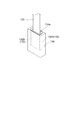
- FIG. 5 is a diagram showing a step in manufacturing the light detection unit of FIG.
- the light detection unit 100 according to the embodiment of the present invention will be described with reference to FIG.
- a light detection unit 100 includes a light detection unit 110 including a photomultiplier tube 1 described later, a long flat flexible wiring board 120, and a voltage division unit including a voltage division substrate 132 described later. 130.
- the photomultiplier tube 1 is a planar photomultiplier tube having a transmission type photocathode, and is an upper frame (second substrate) 2, a side wall frame 3, and a side wall frame 3 with respect to the upper frame 2. And a casing 5 that is an envelope composed of a lower frame (first substrate) 4 facing each other.
- the photomultiplier tube 1 is an electron tube in which the incident direction of light on the photocathode and the electron multiplying direction at the electron multiplier section intersect. That is, in the photomultiplier tube 1, when light is incident from the direction intersecting the plane formed by the lower frame 4, the photoelectrons emitted from the photocathode are incident on the electron multiplier, and the lower frame 4 is configured.
- This is an electron tube in which secondary electrons are cascade-amplified in the plane direction of the plane to take out a signal from the anode part.
- the upstream side (photocathode side) of the electron multiplication path is referred to as “one end side” and the downstream side (anode side) is referred to as “ The other end side. Subsequently, each component of the photomultiplier tube 1 will be described in detail.
- the upper frame 2 is configured with a wiring board 20 whose main material is a rectangular flat plate-like insulating ceramic as a base material.
- a wiring board a multilayer wiring board using LTCC (Low Temperature Co-fired Ceramics) or the like capable of finely designing a wiring pattern and freely designing front and back wiring patterns is used.
- the wiring substrate 20 is electrically connected to the side wall frame 3, a photocathode 41 (to be described later), a focusing electrode 31, a wall electrode 32, an electron multiplying portion 33, and an anode portion 34 to be externally connected.
- a plurality of conductive terminals 201A to 201D for supplying power from and extracting signals from are provided.
- the conductive terminal 201A is used for supplying power to the side wall frame 3, the conductive terminal 201B is used for supplying power to the photocathode 41, the focusing electrode 31, and the wall electrode 32.
- the conductive terminal 201C is supplied to the electron multiplier 33.
- the conductive terminal 201D is provided for feeding power and extracting signals from the anode section 34, respectively.
- conductive terminals 201A to 201D are mutually connected to the conductive film and conductive terminals on the insulating facing surface 20a facing the main surface 20b inside the wiring substrate 20, and these conductive films, conductive
- the conductive terminal is connected to the side wall frame 3, the photocathode 41, the focusing electrode 31, the wall electrode 32, the electron multiplier section 33, and the anode section 34.
- the upper frame 2 is not limited to the multilayer wiring board provided with the conductive terminals 201, and is made of an insulating material such as a glass substrate through which conductive terminals for supplying power from outside and taking out signals are provided. A plate-like member may be used.
- the side wall frame 3 is configured with a rectangular flat silicon substrate 30 as a base material.
- a penetrating portion 301 surrounded by a frame-like side wall portion 302 is formed from the main surface 30a of the silicon substrate 30 toward the surface 30b facing the main surface 30a.
- the through portion 301 has a rectangular opening, and the outer periphery thereof is formed along the outer periphery of the silicon substrate 30.
- the wall-shaped electrode 32, the focusing electrode 31, the electron multiplier part 33, and the anode part 34 are arrange
- the wall electrode 32, the focusing electrode 31, the electron multiplying unit 33, and the anode unit 34 are formed by processing the silicon substrate 30 by RIE (Reactive Ion Etching) processing or the like, and uses silicon as a main material.
- the wall-like electrode 32 is a frame-like electrode formed so as to surround a photocathode 41 (to be described later) when viewed from a direction facing a facing surface 40a of the glass substrate 40 to be described later (substantially perpendicular to the facing surface 40a).
- the focusing electrode 31 is an electrode for converging photoelectrons emitted from the photocathode 41 and guiding the photoelectrons to the electron multiplier 33, and is provided between the photocathode 41 and the electron multiplier 33.
- the electron multiplier 33 is composed of N stages (N is an integer of 2 or more) of dynodes (electron multipliers) set at different potentials along the electron multiplication direction from the photocathode 41 toward the anode 34. And has a plurality of electron multiplication paths (electron multiplication channels) extending in the electron multiplication direction across the stages. Further, the anode part 34 is arranged at a position sandwiching the electron multiplying part 33 together with the photocathode 41.
- the wall electrode 32, the focusing electrode 31, the electron multiplying portion 33, and the anode portion 34 are respectively provided with an anodic bonding, a diffusion bonding, and a sealing material such as a low melting point metal (for example, indium) on the lower frame 4. It is fixed by the joining etc. which were used, and is arrange
- a low melting point metal for example, indium
- the lower frame 4 is configured with a rectangular flat glass substrate 40 as a base material.
- the glass substrate 40 is opposed to the facing surface 20 a of the wiring substrate 20 by glass that is an insulating material, and forms a facing surface 40 a that is the inner surface of the housing 5.
- a portion facing the penetrating portion 301 of the side wall frame 3 (a portion other than the joining region with the side wall portion 302) is located at the end opposite to the anode portion 34 side at the transmission type photocathode.
- the photocathode 41 is formed.
- a plurality of rectangular recesses 42 for preventing the multiplication electrons from being incident on the facing surface 40a are formed in the portion where the electron multiplying portion 33 and the anode portion 34 are mounted on the facing surface 40a.
- the plurality of dynodes and the anode 34 constituting the electron multiplying unit 33 are arranged on an intermediate portion 42 a that is a plane portion between the plurality of depressions 42.
- the photomultiplier tube 1 of the light detection unit 110 is a planar photomultiplier tube having a plurality of (N-stage) electron multipliers 33, and as shown in FIG.
- the resin case 111 is provided with a slit 111 a in a region corresponding to the photocathode 41.
- the photomultiplier tube 1 is electrically connected to one end 120a of the flexible wiring board 120. That is, the wiring of the flexible wiring board 120 is electrically connected to the conductive terminals 201A to 201D of the photomultiplier tube 1. It should be noted that a signal line 140 provided separately from the flexible wiring board 120 is used for taking out the anode signal of the photomultiplier tube 1. The signal line 140 may be omitted by accommodating the anode signal extraction path of the photomultiplier tube 1 in the flexible wiring board 120.
- the other end 120 b of the flexible wiring board 120 is electrically connected to the voltage dividing board 132 of the voltage dividing part 130.
- the voltage dividing unit 130 includes a voltage dividing substrate 132, a resin case 134 that accommodates the voltage dividing substrate 132, and an insulating resin 136.
- the partial pressure substrate 132 includes a first substrate 132A and a second substrate 132B.
- the voltage dividing substrate 132 and the flexible wiring substrate 120 are coupled to each other so that the end portion 120b of the flexible wiring substrate 120 is sandwiched between the substrates 132A and 132B.
- a voltage dividing circuit having a voltage dividing element array D composed of a plurality of voltage dividing elements is formed on the voltage dividing substrate 132.
- the voltage dividing element array D includes a plurality of resistance elements R connected in series, and divides a high voltage applied to the voltage dividing circuit via the high voltage cable 150.
- the voltage to be fed to each stage of the electron multiplier section 33 of the photomultiplier tube 1 is generated.
- the generated voltage is fed to the photomultiplier tube 1 through the flexible wiring board 120.
- the voltage dividing circuit of the voltage dividing substrate 132 includes a capacitor C connected in parallel with the voltage dividing element array D in addition to the voltage dividing element array D, as shown in FIG.
- the voltage dividing circuit functions even without this capacitor C, but having the capacitor C connected in this way can be used as a noise return path when noise is added to the high-voltage cable 150.
- the situation where the noise affects the photomultiplier tube 1 through the flexible wiring board 120 can be suppressed.
- As the capacitor C a small ceramic capacitor having high withstand voltage capability can be adopted.
- the voltage dividing circuit is not limited to the voltage dividing circuit described above, taking into consideration the collection efficiency of photoelectrons emitted from the photocathode 41 of the photomultiplier tube 1, the gain in the electron multiplier 33, the pulse linearity characteristics, and the like. And can be changed as appropriate.
- the resin case 134 is a rectangular parallelepiped case having a dimension that covers the partial pressure substrate 132 as a whole, and is made of an insulating resin, for example, an ABS resin.
- the resin case 134 is provided with an opening 134a for allowing the flexible wiring board 120 to pass through by opening one end surface thereof.
- the insulating resin 136 is formed in the resin case 134 so as to fill a space between the resin case 134 and the voltage dividing substrate 132, and is made of, for example, a silicone resin. That is, the insulating resin 136 completely covers the periphery of the voltage dividing substrate 132 in the resin case 134.
- the insulating resin 136 that covers the voltage dividing substrate 132 includes at least voltage resistance (high insulation), flame retardance (inhibition of ignition due to heat generation), and low water absorption (elements and resins resulting from moisture intrusion). In addition, high fluidity when uncured is required to reliably cover the periphery of the partial pressure substrate 132 in the manufacturing procedure described later.
- the insulating resin 136 is not limited to the silicone resin as long as the resin has these characteristics, and may be a urethane resin, an epoxy resin, or the like.
- the voltage dividing unit 130 described above can be manufactured by the following procedure.
- the photomultiplier tube 1 is electrically connected to one end portion 120 a of the flexible wiring substrate 120, and the voltage dividing substrate 132 is electrically connected to the other end portion 120 b of the flexible wiring substrate 120.
- the resin case is formed so that the voltage dividing substrate 132 (132 ⁇ / b> A, 132 ⁇ / b> B) to which the flexible wiring substrate 120 is connected faces downward so that the voltage dividing substrate 132 does not contact the inner wall of the resin case 134.
- the uncured insulating resin to be the insulating resin 136 is injected from the opening 134a and filled so that the partial pressure substrate 132 is completely filled.
- the periphery of the voltage dividing substrate 132 in the resin case 134 is completely covered with the uncured insulating resin.
- the uncured insulating resin is cured by a predetermined method, whereby the partial pressure substrate 132 is completely covered with the cured insulating resin 136.
- the injection of uncured insulating resin into the resin case 134 is not limited to the opening 134a, and may be injected from an opening other than the opening 134a.
- an uncured insulating resin to be the insulating resin 136 is poured into the resin case 134 from the opening 134a in advance, and then the partial pressure substrate 132 is completely accommodated in the resin case 134.
- the periphery of the voltage dividing substrate 132 in the case 134 may be completely covered with an uncured insulating resin.
- the partial pressure substrate 132 may not be in contact with the inner wall of the resin case 134 before the resin is cured.
- the photomultiplier tube 1 and the voltage dividing substrate 132 are electrically connected via the flexible wiring substrate 120. Therefore, the posture of the photomultiplier tube 1 and the relative position with respect to the voltage dividing substrate 132 can be freely set within the allowable range of flexibility and length of the flexible wiring substrate 120. Specifically, the direction in which the photocathode 41 of the photomultiplier tube 1 is directed (photodetection direction) is oriented in a desired direction without being limited by the arrangement state of the voltage dividing substrate 132 or the photomultiplier tube. It may be arranged on a different plane from the one partial pressure substrate 132. Therefore, the light detection unit 110 including the photomultiplier tube 1 has a high degree of freedom in installation.
- the insulating resin 136 in the resin case 134 covers the periphery of the voltage dividing substrate 132, so that the voltage withstand capability of the voltage dividing substrate 132 is improved. Further, by further covering the insulating resin 136 covering the voltage dividing substrate 132 with an insulating resin case 134, the voltage resistance is further improved, and in addition, impact resistance, environmental stability, and easy handling are improved. The improvement of the property is also aimed at. As a result, restrictions on the installation conditions of the voltage dividing substrate 132 are alleviated. As a result, the light detection unit 100 as a whole is improved in installation flexibility and can be applied to a wider range of uses.
- the space between the resin case 134 and the voltage dividing substrate 132 is completely filled with the insulating resin 136 in the resin case 134.
- the ABS resin is about 14 to 20 kV and the silicone resin is about 27 kV.
- the silicone resin of the insulating resin 136 is higher.
- the space between the resin case 134 and the voltage dividing substrate 132 is insulated so that the periphery of the voltage dividing substrate 132 is completely covered with the insulating resin 136, compared to the case where the voltage dividing substrate 132 contacts the resin case 134.
- the embodiment filled with the conductive resin 136 can achieve higher voltage resistance.
- the ABS resin is about 0.2 to 0.3 W / m ⁇ k
- the silicone resin is about 0.5 W / m ⁇ k
- the silicone resin of the insulating resin 136 is higher.
- the periphery of the voltage dividing substrate 132 is completely covered with the insulating resin 136, whereby the heat generated in the voltage dividing substrate 132 can be efficiently conducted, and the heat is quickly released out of the resin case 134 from the opening 134a. Is done.
- a boundary portion 123 between the portion 121 in contact with the voltage dividing substrate 132 and the portion 122 not in contact with the voltage dividing substrate 132 in the flexible wiring substrate 120 is covered with an insulating resin 136. Therefore, when an external force in a bending direction is applied to the boundary portion 123 of the flexible wiring board 120, the bending stress is relaxed by the insulating resin 136. That is, the insulating resin 136 makes it difficult for excessive bending stress to be applied to the boundary portion 123 of the flexible wiring board 120. Accordingly, disconnection at the boundary portion 123 of the flexible wiring board 120 is effectively suppressed.
- the insulating resin 136 in the resin case 134 covers the entire circumference of the flexible wiring board 120 in the opening 134a. If the entire circumference of the flexible wiring board 120 of the portion 124 in the opening 134a is not covered with the insulating resin 136, the flexible wiring board 120 may come into contact with the resin case 134 at the position of the opening 134a. The disconnection of the flexible wiring board 120 may occur due to the contact stress accompanying the contact. On the other hand, in the above-described embodiment, since the insulating resin 136 covers the entire circumference of the flexible wiring board 120 in the opening 134a, the situation where the flexible wiring board 120 contacts the resin case 134 is suppressed. The broken wire is less likely to occur.
- the boundary portion 124 where the flexible wiring board 120 protrudes from the insulating resin 136 in the opening 134 a is formed in a state in which the insulating resin 136 crawls up along the flexible wiring board 120.
- the scooping-up portion supports the boundary portion 124 region of the flexible wiring board 120, so that the situation where the flexible wiring board 120 contacts the resin case 134 is further suppressed.
- the silicone resin or the like constituting the insulating resin 136 is elastically deformed to some extent, it also has a function of absorbing vibration. Therefore, even when the light detection unit 100 is installed in an environment where the voltage dividing unit 130 vibrates, the vibration is suppressed by the insulating resin 136, and the vibration does not easily reach the voltage dividing substrate 132. In particular, as shown in FIG. 4, when the voltage dividing circuit of the voltage dividing substrate 132 includes the capacitor C, microcracks are generated in the capacitor C due to vibration and impact, and the function is deteriorated.
- the insulating resin 136 covers the periphery of the voltage dividing substrate 132, so that the resistance to vibration and impact of the voltage dividing substrate 132 is improved, and the voltage dividing circuit including the capacitor C is used as the voltage dividing substrate. Even in the case where the capacitor 132 is formed, a situation in which the function of the capacitor C is deteriorated due to the micro crack is suppressed.
- the present invention is not limited to the above-described embodiment, and various modifications are possible.
- the partial pressure substrate constituted by two substrates is shown as the partial pressure substrate, it can be appropriately changed to an aspect constituted by one substrate or an aspect constituted by three or more substrates.
- the photomultiplier tube is not limited to the photomultiplier tube having the configuration shown in FIG. 2, and various planar photomultiplier tubes can be employed.
Landscapes
- Engineering & Computer Science (AREA)
- Manufacturing & Machinery (AREA)
- Measurement Of Radiation (AREA)
- Electron Tubes For Measurement (AREA)
Abstract
本発明の一形態に係る光検出ユニット(100)においては、光電子増倍管(1)と分圧基板(132)とが、フレキシブル配線基板(120)を介して電気的に接続されているため、光電子増倍管(1)の姿勢を自在に設定でき、光電子増倍管(1)における高い設置自由度を有する。その上、分圧部(130)において、樹脂ケース(134)内の絶縁性樹脂(136)が分圧基板(132)の周囲を覆うことで、分圧基板(132)の耐電圧能の向上が図られている。それにより、分圧基板(132)の設置条件に関する制約が軽減され、その結果、光検出ユニット(100)全体として設置自由度の向上が図られ、より広い用途への応用が可能となる。
Description
本発明は、外部からの入射光を検出する平面型の光電子増倍管を含む光検出ユニットおよびその製造方法に関する。
従来から、微細加工技術を利用した小型の光電子増倍管の開発が進められている。例えば、透光性の絶縁基板上に光電面、ダイノード、及びアノードが配置された平面型の光電子増倍管が知られている(特許文献1参照)。このような構造によって、微弱光の検出が実現されるとともに、装置の小型化も図られている。
上述した従来の平面型の光電子増倍管では、高電圧が印加される分圧部とのワンチップ化を想定している。しかしながら、分圧部は発熱体であるため、その発熱の光電子増倍管への影響を避けるためには、分圧部を光電子増倍管から離間させることが好ましい。特に平面型の光電子増倍管の場合、光電面等の、高温による影響を受けやすい構成が平面部に近接するために、より発熱の影響を受けやすくなってしまう。
そこで、発明者らは、分圧部と光電子増倍管とを分離した上で、これらを電気的に接続する光検出ユニットについて検討を重ねた。その結果、分圧部と光電子増倍管との間をフレキシブル配線基板で接続する技術に至った。
このような光検出ユニットによれば、フレキシブル配線基板の柔軟性により、光電子増倍管の姿勢を自在に設定できるため、光電子増倍管における高い設置自由度を実現することができる。発明者らは、鋭意検討の末、光検出ユニットにおいてさらに設置自由度を向上させる技術を見出した。
すなわち、本発明は、設置自由度の向上が図られた、光電子増倍管を含む光検出ユニットおよびその製造方法を提供することを目的とする。
本発明の一態様に係る光検出ユニットは、複数段の電子増倍部を有する平面型の光電子増倍管と、電子増倍部の各段へ給電する電圧を生成する分圧基板と、一端部において光電子増倍管と電気的に接続されるとともに、他端部において分圧基板と電気的に接続されるフレキシブル配線基板とを備える光検出ユニットであって、分圧基板を収容する樹脂ケースと、樹脂ケース内において分圧基板の周囲を覆う絶縁性樹脂とをさらに備える。
この光検出ユニットにおいては、平面型の光電子増倍管と分圧基板とが、フレキシブル配線基板を介して電気的に接続されているため、光電子増倍管の姿勢を自在に設定でき、光電子増倍管における高い設置自由度を有する。加えて、分圧基板が樹脂ケースに収容されるとともに、その樹脂ケース内において絶縁性樹脂で周囲を覆われているため、分圧基板の耐電圧能の向上が図られている。それにより、分圧基板の設置条件に関する制約が軽減され、その結果、光検出ユニット全体としてさらなる設置自由度の向上が図られ、より広い用途への応用が可能となる。
また、樹脂ケース内において、樹脂ケースと分圧基板との間の空間が絶縁性樹脂で充たされている態様であってもよい。この場合、分圧基板が樹脂ケースに接触する事態が抑制されるため、より高い耐電圧能を実現することができる。
また、フレキシブル配線基板のうち、分圧基板に接する部分と接しない部分との境界部分が絶縁性樹脂で覆われている態様であってもよい。この場合、フレキシブル配線基板の境界部分における屈曲応力が絶縁性樹脂により緩和されるため、境界部分における断線が抑制される。
また、樹脂ケースが、フレキシブル配線基板が通る開口を有し、樹脂ケース内の絶縁性樹脂が、開口におけるフレキシブル配線基板を覆う態様であってもよい。この場合、フレキシブル配線基板が樹脂ケースに接触する事態が抑制されるため、フレキシブル配線基板の樹脂ケースへの接触に伴う接触応力による断線が抑制される。
また、分圧基板がコンデンサを含んでいる態様であってもよい。分圧基板の周囲を覆う絶縁性樹脂が振動吸収するため、振動により、分圧基板に含まれるコンデンサの機能が劣化する事態が抑制される。
本発明の一態様に係る光検出ユニットの製造方法は、複数段の電子増倍部を有する平面型の光電子増倍管と、電子増倍部の各段へ給電する電圧を生成する分圧基板とを備える光検出ユニットの製造方法において、フレキシブル配線基板の一端部に、光電子増倍管を電気的に接続する工程と、フレキシブル配線基板の他端部に、分圧基板を電気的に接続する工程と、フレキシブル配線基板と電気的に接続された分圧基板を樹脂ケース内に収容し、樹脂ケース内において分圧基板を未硬化の絶縁性樹脂で覆う工程と、樹脂ケース内の未硬化の絶縁性樹脂を硬化する工程とを有する。
この光検出ユニットの製造方法によれば、平面型の光電子増倍管と分圧基板とが、フレキシブル配線基板を介して電気的に接続された光検出ユニットが作製される。このような光検出ユニットにおいては、光電子増倍管の姿勢を自在に設定でき、光電子増倍管における高い設置自由度を有する。加えて、分圧基板を樹脂ケース内において未硬化の絶縁性樹脂で覆う工程および樹脂ケース内の未硬化の絶縁性樹脂を硬化する工程により、分圧基板が樹脂ケース内において絶縁性樹脂で周囲を覆われるため、分圧基板の耐電圧能の向上が図られる。それにより、分圧基板の設置条件に関する制約が軽減され、その結果、光検出ユニット全体としてさらなる設置自由度の向上が図られ、より広い用途への応用が可能となる。
本発明によれば、設置自由度の向上が図られた、光電子増倍管を含む光検出ユニットおよびその製造方法が提供される。
以下、添付図面を参照して、本発明の好適な実施形態について詳細に説明する。なお、説明において、同一要素又は同一機能を有する要素には、同一符号を用いることとし、重複する説明は省略する。
本発明の実施形態に係る光検出ユニット100について、図1を参照しつつ説明する。
図1に示すように、光検出ユニット100は、後述する光電子増倍管1を含む光検出部110と、長尺平板状のフレキシブル配線基板120と、後述する分圧基板132を含む分圧部130とを備えている。
まず、光検出部110の光電子増倍管1について、図2を参照しつつ説明する。
光電子増倍管1は、透過型の光電面を有する平面型の光電子増倍管であって、上側フレーム(第2の基板)2と、側壁フレーム3と、上側フレーム2に対して側壁フレーム3を挟んで対向する下側フレーム(第1の基板)4により構成された外囲器である筐体5を備える。この光電子増倍管1は、光電面への光の入射方向と、電子増倍部での電子の増倍方向が交差する電子管である。つまり、光電子増倍管1は、下側フレーム4が構成する平面と交わる方向から光が入射されると、光電面から放出された光電子が電子増倍部に入射し、下側フレーム4が構成する平面の面方向に二次電子をカスケード増幅し、陽極部から信号を取り出す電子管である。
なお、以下の説明においては、電子増倍方向に沿って、電子増倍路(電子増倍チャネル)の上流側(光電面側)を“一端側”とし、下流側(陽極部側)を“他端側”とする。引き続いて、光電子増倍管1の各構成要素について詳細に説明する。
図2に示されたように、上側フレーム2は、矩形平板状の絶縁性のセラミックスを主材料とする配線基板20を基材として構成されている。このような配線基板としては、微細な配線設計が可能で、かつ表裏の配線パターンを自由に設計できるLTCC(Low Temperature Co-fired Ceramics:低温同時焼成セラミックス)等を用いた多層配線基板が用いられる。配線基板20には、その主面20b上に、側壁フレーム3、後述する光電面41、集束電極31、壁状電極32、電子増倍部33、及び陽極部34と電気的に接続されて外部からの給電や信号の取り出しを行う複数の導電性端子201A~201Dが設けられている。導電性端子201Aは側壁フレーム3の給電用として、導電性端子201Bは、光電面41、集束電極31、及び壁状電極32の給電用として、導電性端子201Cは、電子増倍部33の給電用として、導電性端子201Dは、陽極部34の給電及び信号取り出し用として、それぞれ設けられている。これらの導電性端子201A~201Dは、配線基板20の内部で主面20bに対して対向する絶縁性の対向面20a上の導電膜や導電性端子と相互に接続され、これらの導電膜、導電性端子と側壁フレーム3、光電面41、集束電極31、壁状電極32、電子増倍部33、及び陽極部34とが接続される。また、上側フレーム2は、導電性端子201を設けた多層配線基板に限らず、外部からの給電や信号の取り出しを行う導電性端子が貫通して設けられた、ガラス基板等の絶縁材料からなる板状部材でもよい。
側壁フレーム3は、矩形平板状のシリコン基板30を基材として構成されている。シリコン基板30の主面30aからそれに対向する面30bに向かって、枠状の側壁部302に囲まれた貫通部301が形成されている。この貫通部301はその開口が矩形であって、その外周はシリコン基板30の外周に沿うように形成されている。
この貫通部301内には、一端側から他端側に向かって、壁状電極32、集束電極31、電子増倍部33、及び陽極部34が配置されている。これらの壁状電極32、集束電極31、電子増倍部33、及び陽極部34は、シリコン基板30をRIE(Reactive Ion Etching)加工等によって加工することにより形成され、シリコンを主要材料としている。
壁状電極32は、後述するガラス基板40の対向面40aと正対する方向(対向面40aに対する略垂直方向)から見て、後述する光電面41を取り囲むように形成された枠状の電極である。また、集束電極31は、光電面41から放出された光電子を集束して電子増倍部33へと導くための電極であり、光電面41と電子増倍部33との間に設けられている。
電子増倍部33は、光電面41から陽極部34に向う電子増倍方向に沿って異なる電位に設定されるN段(Nは2以上の整数)のダイノード(電子増倍部)から構成されており、各段を跨って電子増倍方向に伸びる、複数の電子増倍路(電子増倍チャネル)を有している。また、陽極部34は光電面41とともに電子増倍部33を挟む位置に配置される。
これら壁状電極32、集束電極31、電子増倍部33、及び陽極部34は、それぞれ、下側フレーム4に陽極接合、拡散接合、さらには低融点金属(例えばインジウム)等の封止材を用いた接合等によって固定されており、これにより該下側フレーム4上に二次元的に配置される。
下側フレーム4は、矩形平板状のガラス基板40を基材として構成されている。このガラス基板40は、絶縁材料であるガラスによって配線基板20の対向面20aに対向し、筐体5の内面である対向面40aを形成する。対向面40a上における、側壁フレーム3の貫通部301に対向する部位(側壁部302との接合領域以外の部位)であって、陽極部34側と反対側の端部には、透過型光電面である光電面41が形成されている。また、対向面40a上の電子増倍部33及び陽極部34が搭載される部位には、増倍電子の対向面40aへの入射を防止するための、複数の矩形状の窪み部42が形成されている。なお、電子増倍部33を構成する複数段のダイノード、及び陽極34は、複数の窪み部42の間の平面部である中間部42a上に配置される。
以上で説明したように、光検出部110の光電子増倍管1は、複数段(N段)の電子増倍部33を有する平面型の光電子増倍管であり、図1に示すように、光電面41に対応する領域にスリット111aが設けられた樹脂ケース111に収容されている。
また、光電子増倍管1は、フレキシブル配線基板120の一端部120aに電気的に接続されている。すなわち、フレキシブル配線基板120の配線が、光電子増倍管1の各導電性端子201A~201Dと電気的に接続されている。なお、光電子増倍管1の陽極信号の取り出しには、フレキシブル配線基板120とは別体で設けられた信号線140を用いる。なお、光電子増倍管1の陽極信号の取り出し経路をフレキシブル配線基板120内に収めることで、信号線140を省略してもよい。
フレキシブル配線基板120の他端部120bは、分圧部130の分圧基板132に電気的に接続されている。
以下、分圧部130の構成について、図3を参照しつつ詳細に説明する。
図3に示すように、分圧部130は、分圧基板132と、分圧基板132を収容する樹脂ケース134と、絶縁性樹脂136とを備えている。
分圧基板132は、第1の基板132Aと第2の基板132Bとで構成されている。そして、これらの基板132A、132Bの間に、フレキシブル配線基板120の端部120bが挟まれるようにして、分圧基板132とフレキシブル配線基板120とが互いに結合されている。
分圧基板132には、図4に示すように、複数の分圧素子からなる分圧素子列Dを有する分圧回路が形成されている。図4に示した分圧回路においては、分圧素子列Dは、直列に接続された複数の抵抗素子Rからなり、分圧回路に高圧ケーブル150を介して印加される高電圧を分圧して、光電子増倍管1の電子増倍部33の各段へ給電されるべき電圧を生成する。生成された電圧は、フレキシブル配線基板120を介して、光電子増倍管1に給電される。
なお、分圧基板132の分圧回路は、図4に示すように、分圧素子列Dの他に、分圧素子列Dと並列に接続されたコンデンサCを有している。分圧回路は、このコンデンサCがない場合でも機能するが、このように接続されたコンデンサCを有することで、高圧ケーブル150にノイズが加わってしまった際のノイズのリターンパスとして用いることができ、当該ノイズがフレキシブル配線基板120を介して光電子増倍管1へ影響してしまう事態を抑制することができる。なお、コンデンサCには、耐電圧能が高く、小型なセラミックコンデンサが採用され得る。また、分圧回路は、上述した分圧回路に限定されず、光電子増倍管1の光電面41から放出される光電子の収集効率や電子増倍部33における利得やパルスリニアリティ特性などを考慮して、適宜変更可能である。
樹脂ケース134は、分圧基板132を全体的に覆う寸法を有する直方体状ケースであり、絶縁性を有する樹脂、たとえばABS樹脂で構成されている。樹脂ケース134は、その一端面が開放されることで、フレキシブル配線基板120を通すための開口134aが設けられている。
絶縁性樹脂136は、樹脂ケース134内において、樹脂ケース134と分圧基板132との間の空間を充たすように形成されており、たとえばシリコーン樹脂で構成されている。すなわち、絶縁性樹脂136は、樹脂ケース134内において分圧基板132の周囲を完全に覆っている。なお、分圧基板132を覆う絶縁性樹脂136には、少なくとも耐電圧性(高い絶縁性)、難燃性(発熱に起因する発火抑制)、低吸水性(水分の浸入に起因する素子や樹脂の劣化抑制)が求められ、さらには、後述する作製手順において分圧基板132の周囲を確実に覆うために未硬化時における高い流動性が求められる。絶縁性樹脂136は、これらの特性を備える樹脂であれば、シリコーン樹脂に限らず、ウレタン樹脂やエポキシ樹脂等であってもよい。
以上で説明した分圧部130は、以下の手順により作製することができる。
すなわち、まず、フレキシブル配線基板120の一端部120aに光電子増倍管1を電気的に接続するとともに、フレキシブル配線基板120の他端部120bに、分圧基板132を電気的に接続する。次に、図5に示すように、フレキシブル配線基板120が接続された分圧基板132(132A、132B)を下方に向けて、分圧基板132が樹脂ケース134の内壁に接触しないように樹脂ケース134内に完全に収容し、その後、絶縁性樹脂136となるべき未硬化の絶縁性樹脂を開口134aから注入し、分圧基板132が完全に埋まるように充填する。その結果、樹脂ケース134内において分圧基板132の周囲が、未硬化の絶縁性樹脂によって完全に覆われる。その後、未硬化の絶縁性樹脂を所定の方法で硬化させることで、分圧基板132が硬化された絶縁性樹脂136によって完全に覆われることとなる。なお、未硬化の絶縁性樹脂の樹脂ケース134内への注入は、開口134aからに限らず、開口134aとは別の開口部から注入してもよい。
なお、予め絶縁性樹脂136となるべき未硬化の絶縁性樹脂を開口134aから樹脂ケース134内に注入しておき、その後、分圧基板132を樹脂ケース134内に完全に収容することで、樹脂ケース134内において分圧基板132の周囲を、未硬化の絶縁性樹脂で完全に覆ってもよい。また、未硬化の絶縁性樹脂を注入してから、樹脂が硬化しないうちに分圧基板132を樹脂ケース134の内壁に接触しないような状態としてもよい。
以上で説明した光検出ユニット100においては、光電子増倍管1と分圧基板132とが、フレキシブル配線基板120を介して電気的に接続されている。そのため、フレキシブル配線基板120の柔軟性と長さの許容範囲内で、光電子増倍管1の姿勢や分圧基板132に対する相対位置を自在に設定できる。具体的には、分圧基板132の配置状態等に制限されることなく、光電子増倍管1の光電面41を向ける方向(光検出方向)を所望の方向に配向させたり、光電子増倍管1の分圧基板132とは異なる平面上に配置したりすることができる。したがって、光電子増倍管1を含む光検出部110は高い設置自由度を有する。
その上、分圧部130において、樹脂ケース134内の絶縁性樹脂136が分圧基板132の周囲を覆うことで、分圧基板132の耐電圧能の向上が図られている。また、分圧基板132を覆う絶縁性樹脂136を、絶縁性の樹脂ケース134でさらに覆うことで、さらなる耐電圧能の向上が図られ、加えて、耐衝撃性や環境安定性、取扱いの容易性の向上も図られている。それにより、分圧基板132の設置条件に関する制約が軽減され、その結果、光検出ユニット100全体として設置自由度の向上が図られ、より広い用途への応用が可能となる。
特に、上述した実施形態においては、樹脂ケース134内において、樹脂ケース134と分圧基板132との間の空間が絶縁性樹脂136で完全に充たされている。
ここで、樹脂ケース134を構成するABS樹脂と、絶縁性樹脂136を構成するシリコーン樹脂とで、絶縁性(絶縁破壊電圧)を比較した場合、ABS樹脂が約14~20kV、シリコーン樹脂が約27kVであり、絶縁性樹脂136のシリコーン樹脂のほうが高くなっている。
そのため、分圧基板132が樹脂ケース134に接触する態様よりも、分圧基板132が完全に周囲を絶縁性樹脂136で覆われるように樹脂ケース134と分圧基板132との間の空間が絶縁性樹脂136で充たされる態様のほうが、より高い耐電圧能を実現することができる。
また、樹脂ケース134を構成するABS樹脂と、絶縁性樹脂136を構成するシリコーン樹脂とで、放熱性(熱伝導率)を比較した場合、ABS樹脂が約0.2~0.3W/m・k、シリコーン樹脂が約0.5W/m・kであり、絶縁性樹脂136のシリコーン樹脂のほうが高くなっている。
そのため、絶縁性樹脂136により分圧基板132の周囲が完全に覆われることで、分圧基板132に生じる熱を効率よく伝導することができ、熱が開口134aから速やかに樹脂ケース134外に放出される。
さらに、図3に示すように、フレキシブル配線基板120のうち、分圧基板132に接する部分121と接しない部分122との境界部分123が絶縁性樹脂136で覆われている。そのため、フレキシブル配線基板120の境界部分123に、屈曲する向きの外力が加わった場合に、その屈曲応力が絶縁性樹脂136により緩和される。すなわち、絶縁性樹脂136により、フレキシブル配線基板120の境界部分123に、過剰な屈曲応力が加わりにくくなっている。したがって、フレキシブル配線基板120の境界部分123における断線が効果的に抑制されている。
加えて、樹脂ケース134内の絶縁性樹脂136が、開口134a内においてフレキシブル配線基板120の全周を覆っている。開口134aにおける部分124のフレキシブル配線基板120の全周が絶縁性樹脂136で覆われていない場合には、開口134aの位置において、フレキシブル配線基板120が樹脂ケース134に接触する事態が生じ、場合によっては、その接触に伴う接触応力によりフレキシブル配線基板120の断線が生じうる。一方、上述した実施形態においては、開口134a内においてフレキシブル配線基板120の全周を絶縁性樹脂136が覆っているため、フレキシブル配線基板120が樹脂ケース134に接触する事態が抑制されており、上記した断線は生じにくくなっている。
また、開口134a内においてフレキシブル配線基板120が絶縁性樹脂136から突出する境界部124においては、フレキシブル配線基板120に沿って絶縁性樹脂136が這い上がった状態で形成されている。這い上がり部がフレキシブル配線基板120の境界部124領域を支持することで、さらにフレキシブル配線基板120が樹脂ケース134に接触する事態が抑制されている。
また、絶縁性樹脂136を構成するシリコーン樹脂等は、ある程度弾性変形するため、振動吸収の機能も備えている。そのため、光検出ユニット100を、分圧部130が振動する環境に設置した場合であっても、その振動が絶縁性樹脂136によって抑制され、分圧基板132まで振動が達しにくくなっている。特に、図4に示したように、分圧基板132の分圧回路がコンデンサCを有する場合には、振動や衝撃により、コンデンサCにマイクロクラックが生じて機能が劣化してしまう。上述した実施形態においては、絶縁性樹脂136が分圧基板132の周囲を覆うことで、分圧基板132の振動や衝撃に対する耐性が向上しており、コンデンサCを含む分圧回路が分圧基板132に形成されている場合であっても、コンデンサCにマイクロクラックにより機能が劣化する事態が抑制されている。
なお、本発明は上述した実施形態に限らず、様々な変形が可能である。たとえば、分圧基板として、2枚の基板で構成された分圧基板を示したが、適宜、1枚の基板で構成した態様や3枚以上の基板で構成した態様に変更可能である。また、光電子増倍管としては、図2に示した構成の光電子増倍管に限らず、平面型の様々な光電子増倍管を採用可能である。
1 光電子増倍管
33 電子増倍部
100 光検出ユニット
110 光検出部
120 フレキシブル配線基板
130 分圧部
132 分圧基板
134 樹脂ケース
136 絶縁性樹脂
33 電子増倍部
100 光検出ユニット
110 光検出部
120 フレキシブル配線基板
130 分圧部
132 分圧基板
134 樹脂ケース
136 絶縁性樹脂
Claims (6)
- 複数段の電子増倍部を有する平面型の光電子増倍管と、
前記電子増倍部の各段へ給電する電圧を生成する分圧基板と、
一端部において前記光電子増倍管と電気的に接続されるとともに、他端部において前記分圧基板と電気的に接続されるフレキシブル配線基板と
を備える光検出ユニットであって、
前記分圧基板を収容する樹脂ケースと、
前記樹脂ケース内において前記分圧基板の周囲を覆う絶縁性樹脂と
をさらに備える、光検出ユニット。 - 前記樹脂ケース内において、前記樹脂ケースと前記分圧基板との間の空間が前記絶縁性樹脂で充たされている、請求項1に記載の光検出ユニット。
- 前記フレキシブル配線基板のうち、前記分圧基板に接する部分と接しない部分との境界部分が前記絶縁性樹脂で覆われている、請求項1または2に記載の光検出ユニット。
- 前記樹脂ケースが、前記フレキシブル配線基板が通る開口を有し、
前記樹脂ケース内の絶縁性樹脂が、前記開口における前記フレキシブル配線基板を覆う、請求項1~3のいずれか一項に記載の光検出ユニット。 - 前記分圧基板がコンデンサを含んでいる、請求項1~4のいずれか一項に記載の光検出ユニット。
- 複数段の電子増倍部を有する平面型の光電子増倍管と、前記電子増倍部の各段へ給電する電圧を生成する分圧基板とを備える光検出ユニットの製造方法において、
フレキシブル配線基板の一端部に、前記光電子増倍管を電気的に接続する工程と、
前記フレキシブル配線基板の他端部に、前記分圧基板を電気的に接続する工程と、
前記フレキシブル配線基板と電気的に接続された前記分圧基板を樹脂ケース内に収容し、前記樹脂ケース内において前記分圧基板を未硬化の絶縁性樹脂で覆う工程と、
前記樹脂ケース内の前記未硬化の絶縁性樹脂を硬化する工程と
を有する光検出ユニットの製造方法。
Priority Applications (2)
| Application Number | Priority Date | Filing Date | Title |
|---|---|---|---|
| US14/437,983 US9607814B2 (en) | 2012-10-30 | 2013-08-19 | Photodetection unit and method for manufacturing same |
| CN201380057379.3A CN104769699B (zh) | 2012-10-30 | 2013-08-19 | 光检测单元及其制造方法 |
Applications Claiming Priority (2)
| Application Number | Priority Date | Filing Date | Title |
|---|---|---|---|
| JP2012-238992 | 2012-10-30 | ||
| JP2012238992A JP6151505B2 (ja) | 2012-10-30 | 2012-10-30 | 光検出ユニットおよびその製造方法 |
Publications (1)
| Publication Number | Publication Date |
|---|---|
| WO2014069073A1 true WO2014069073A1 (ja) | 2014-05-08 |
Family
ID=50626995
Family Applications (1)
| Application Number | Title | Priority Date | Filing Date |
|---|---|---|---|
| PCT/JP2013/072102 Ceased WO2014069073A1 (ja) | 2012-10-30 | 2013-08-19 | 光検出ユニットおよびその製造方法 |
Country Status (4)
| Country | Link |
|---|---|
| US (1) | US9607814B2 (ja) |
| JP (1) | JP6151505B2 (ja) |
| CN (1) | CN104769699B (ja) |
| WO (1) | WO2014069073A1 (ja) |
Families Citing this family (1)
| Publication number | Priority date | Publication date | Assignee | Title |
|---|---|---|---|---|
| JP6059554B2 (ja) * | 2013-02-21 | 2017-01-11 | 浜松ホトニクス株式会社 | 光検出ユニット |
Citations (5)
| Publication number | Priority date | Publication date | Assignee | Title |
|---|---|---|---|---|
| JPH06224314A (ja) * | 1992-12-04 | 1994-08-12 | Toshiba Corp | 半導体装置 |
| JP2004031682A (ja) * | 2002-06-26 | 2004-01-29 | Sony Corp | プリント配線基板の製造方法 |
| JP2010267414A (ja) * | 2009-05-12 | 2010-11-25 | Hamamatsu Photonics Kk | 光電子増倍管 |
| JP2011187454A (ja) * | 2004-02-17 | 2011-09-22 | Hamamatsu Photonics Kk | 光電子増倍管及びその製造方法 |
| JP2012204262A (ja) * | 2011-03-28 | 2012-10-22 | Spectratech Inc | 光検出器用高電圧回路 |
Family Cites Families (7)
| Publication number | Priority date | Publication date | Assignee | Title |
|---|---|---|---|---|
| US5264693A (en) | 1992-07-01 | 1993-11-23 | The United States Of America As Represented By The Secretary Of The Navy | Microelectronic photomultiplier device with integrated circuitry |
| US5453609A (en) * | 1993-10-22 | 1995-09-26 | Southeastern Universities Research Assn., Inc. | Non cross talk multi-channel photomultiplier using guided electron multipliers |
| US6852979B1 (en) * | 1998-11-10 | 2005-02-08 | Hamamatsu Photonics K. K. | Photomultiplier tube, photomultiplier tube unit, radiation detector |
| JP4603231B2 (ja) * | 2002-07-19 | 2010-12-22 | パナソニック電工株式会社 | 火災感知器 |
| US7746462B2 (en) * | 2007-05-21 | 2010-06-29 | Kla-Tencor Technologies Corporation | Inspection systems and methods for extending the detection range of an inspection system by forcing the photodetector into the non-linear range |
| CN102468109B (zh) | 2010-10-29 | 2015-09-02 | 浜松光子学株式会社 | 光电倍增管 |
| CN202003946U (zh) | 2010-11-26 | 2011-10-05 | 中国船舶重工集团公司第七一八研究所 | 一种光电倍增管 |
-
2012
- 2012-10-30 JP JP2012238992A patent/JP6151505B2/ja active Active
-
2013
- 2013-08-19 US US14/437,983 patent/US9607814B2/en active Active
- 2013-08-19 CN CN201380057379.3A patent/CN104769699B/zh active Active
- 2013-08-19 WO PCT/JP2013/072102 patent/WO2014069073A1/ja not_active Ceased
Patent Citations (5)
| Publication number | Priority date | Publication date | Assignee | Title |
|---|---|---|---|---|
| JPH06224314A (ja) * | 1992-12-04 | 1994-08-12 | Toshiba Corp | 半導体装置 |
| JP2004031682A (ja) * | 2002-06-26 | 2004-01-29 | Sony Corp | プリント配線基板の製造方法 |
| JP2011187454A (ja) * | 2004-02-17 | 2011-09-22 | Hamamatsu Photonics Kk | 光電子増倍管及びその製造方法 |
| JP2010267414A (ja) * | 2009-05-12 | 2010-11-25 | Hamamatsu Photonics Kk | 光電子増倍管 |
| JP2012204262A (ja) * | 2011-03-28 | 2012-10-22 | Spectratech Inc | 光検出器用高電圧回路 |
Also Published As
| Publication number | Publication date |
|---|---|
| US9607814B2 (en) | 2017-03-28 |
| JP2014089878A (ja) | 2014-05-15 |
| CN104769699B (zh) | 2017-05-31 |
| JP6151505B2 (ja) | 2017-06-21 |
| US20150311049A1 (en) | 2015-10-29 |
| CN104769699A (zh) | 2015-07-08 |
Similar Documents
| Publication | Publication Date | Title |
|---|---|---|
| JP5771447B2 (ja) | 電子増倍器 | |
| JP5290804B2 (ja) | 光電子増倍管 | |
| JP5290805B2 (ja) | 光電子増倍管 | |
| CN101390188B (zh) | 光电倍增管、放射线检测装置以及光电倍增管的制造方法 | |
| JP2010238502A (ja) | 質量分析装置 | |
| JP6474992B2 (ja) | 光検出ユニット | |
| KR20150075347A (ko) | 반도체 패키지, 반도체 모듈 및 반도체 디바이스 | |
| CN101395692B (zh) | 光电倍增管和放射线检测装置 | |
| JP2014036228A (ja) | 対面型光結合素子デバイス及びその製造方法 | |
| CN101390189B (zh) | 光电倍增管和放射线检测装置 | |
| JP6151505B2 (ja) | 光検出ユニットおよびその製造方法 | |
| JP5330083B2 (ja) | 光電子増倍管 | |
| EP2557589B1 (en) | Electron multiplier and photomultiplier tube containing same | |
| JP6059554B2 (ja) | 光検出ユニット | |
| JP5789021B2 (ja) | 光電子増倍管 | |
| US20120091889A1 (en) | Photomultiplier tube | |
| KR101580869B1 (ko) | 전지셀 어셈블리 및 전지셀 어셈블리를 제조하는 방법 | |
| JP2016046146A (ja) | 光検出ユニット | |
| WO2020029726A1 (zh) | 光器件及光模块 | |
| JP5518364B2 (ja) | 光電子増倍管 | |
| JP5497331B2 (ja) | 光電子増倍管 | |
| EP2442347B1 (en) | Photomultiplier tube | |
| JP2009170171A (ja) | イメージ管ユニット |
Legal Events
| Date | Code | Title | Description |
|---|---|---|---|
| 121 | Ep: the epo has been informed by wipo that ep was designated in this application |
Ref document number: 13850062 Country of ref document: EP Kind code of ref document: A1 |
|
| WWE | Wipo information: entry into national phase |
Ref document number: 14437983 Country of ref document: US |
|
| NENP | Non-entry into the national phase |
Ref country code: DE |
|
| 122 | Ep: pct application non-entry in european phase |
Ref document number: 13850062 Country of ref document: EP Kind code of ref document: A1 |