WO2014068969A1 - 非水電解質二次電池 - Google Patents
非水電解質二次電池 Download PDFInfo
- Publication number
- WO2014068969A1 WO2014068969A1 PCT/JP2013/006417 JP2013006417W WO2014068969A1 WO 2014068969 A1 WO2014068969 A1 WO 2014068969A1 JP 2013006417 W JP2013006417 W JP 2013006417W WO 2014068969 A1 WO2014068969 A1 WO 2014068969A1
- Authority
- WO
- WIPO (PCT)
- Prior art keywords
- negative electrode
- rare earth
- active material
- electrolyte secondary
- electrode active
- Prior art date
- Legal status (The legal status is an assumption and is not a legal conclusion. Google has not performed a legal analysis and makes no representation as to the accuracy of the status listed.)
- Ceased
Links
Images

Classifications
-
- H—ELECTRICITY
- H01—ELECTRIC ELEMENTS
- H01M—PROCESSES OR MEANS, e.g. BATTERIES, FOR THE DIRECT CONVERSION OF CHEMICAL ENERGY INTO ELECTRICAL ENERGY
- H01M4/00—Electrodes
- H01M4/02—Electrodes composed of, or comprising, active material
- H01M4/13—Electrodes for accumulators with non-aqueous electrolyte, e.g. for lithium-accumulators; Processes of manufacture thereof
-
- H—ELECTRICITY
- H01—ELECTRIC ELEMENTS
- H01M—PROCESSES OR MEANS, e.g. BATTERIES, FOR THE DIRECT CONVERSION OF CHEMICAL ENERGY INTO ELECTRICAL ENERGY
- H01M4/00—Electrodes
- H01M4/02—Electrodes composed of, or comprising, active material
- H01M4/36—Selection of substances as active materials, active masses, active liquids
- H01M4/362—Composites
- H01M4/366—Composites as layered products
-
- H—ELECTRICITY
- H01—ELECTRIC ELEMENTS
- H01M—PROCESSES OR MEANS, e.g. BATTERIES, FOR THE DIRECT CONVERSION OF CHEMICAL ENERGY INTO ELECTRICAL ENERGY
- H01M10/00—Secondary cells; Manufacture thereof
- H01M10/05—Accumulators with non-aqueous electrolyte
- H01M10/056—Accumulators with non-aqueous electrolyte characterised by the materials used as electrolytes, e.g. mixed inorganic/organic electrolytes
- H01M10/0564—Accumulators with non-aqueous electrolyte characterised by the materials used as electrolytes, e.g. mixed inorganic/organic electrolytes the electrolyte being constituted of organic materials only
- H01M10/0566—Liquid materials
-
- H—ELECTRICITY
- H01—ELECTRIC ELEMENTS
- H01M—PROCESSES OR MEANS, e.g. BATTERIES, FOR THE DIRECT CONVERSION OF CHEMICAL ENERGY INTO ELECTRICAL ENERGY
- H01M4/00—Electrodes
- H01M4/02—Electrodes composed of, or comprising, active material
- H01M4/36—Selection of substances as active materials, active masses, active liquids
- H01M4/38—Selection of substances as active materials, active masses, active liquids of elements or alloys
-
- H—ELECTRICITY
- H01—ELECTRIC ELEMENTS
- H01M—PROCESSES OR MEANS, e.g. BATTERIES, FOR THE DIRECT CONVERSION OF CHEMICAL ENERGY INTO ELECTRICAL ENERGY
- H01M4/00—Electrodes
- H01M4/02—Electrodes composed of, or comprising, active material
- H01M4/36—Selection of substances as active materials, active masses, active liquids
- H01M4/48—Selection of substances as active materials, active masses, active liquids of inorganic oxides or hydroxides
- H01M4/483—Selection of substances as active materials, active masses, active liquids of inorganic oxides or hydroxides for non-aqueous cells
-
- H—ELECTRICITY
- H01—ELECTRIC ELEMENTS
- H01M—PROCESSES OR MEANS, e.g. BATTERIES, FOR THE DIRECT CONVERSION OF CHEMICAL ENERGY INTO ELECTRICAL ENERGY
- H01M4/00—Electrodes
- H01M4/02—Electrodes composed of, or comprising, active material
- H01M4/62—Selection of inactive substances as ingredients for active masses, e.g. binders, fillers
-
- H—ELECTRICITY
- H01—ELECTRIC ELEMENTS
- H01M—PROCESSES OR MEANS, e.g. BATTERIES, FOR THE DIRECT CONVERSION OF CHEMICAL ENERGY INTO ELECTRICAL ENERGY
- H01M10/00—Secondary cells; Manufacture thereof
- H01M10/05—Accumulators with non-aqueous electrolyte
- H01M10/052—Li-accumulators
-
- H—ELECTRICITY
- H01—ELECTRIC ELEMENTS
- H01M—PROCESSES OR MEANS, e.g. BATTERIES, FOR THE DIRECT CONVERSION OF CHEMICAL ENERGY INTO ELECTRICAL ENERGY
- H01M10/00—Secondary cells; Manufacture thereof
- H01M10/05—Accumulators with non-aqueous electrolyte
- H01M10/058—Construction or manufacture
- H01M10/0587—Construction or manufacture of accumulators having only wound construction elements, i.e. wound positive electrodes, wound negative electrodes and wound separators
-
- H—ELECTRICITY
- H01—ELECTRIC ELEMENTS
- H01M—PROCESSES OR MEANS, e.g. BATTERIES, FOR THE DIRECT CONVERSION OF CHEMICAL ENERGY INTO ELECTRICAL ENERGY
- H01M4/00—Electrodes
- H01M4/02—Electrodes composed of, or comprising, active material
- H01M4/36—Selection of substances as active materials, active masses, active liquids
- H01M4/38—Selection of substances as active materials, active masses, active liquids of elements or alloys
- H01M4/386—Silicon or alloys based on silicon
-
- H—ELECTRICITY
- H01—ELECTRIC ELEMENTS
- H01M—PROCESSES OR MEANS, e.g. BATTERIES, FOR THE DIRECT CONVERSION OF CHEMICAL ENERGY INTO ELECTRICAL ENERGY
- H01M4/00—Electrodes
- H01M4/02—Electrodes composed of, or comprising, active material
- H01M4/36—Selection of substances as active materials, active masses, active liquids
- H01M4/48—Selection of substances as active materials, active masses, active liquids of inorganic oxides or hydroxides
- H01M4/52—Selection of substances as active materials, active masses, active liquids of inorganic oxides or hydroxides of nickel, cobalt or iron
- H01M4/525—Selection of substances as active materials, active masses, active liquids of inorganic oxides or hydroxides of nickel, cobalt or iron of mixed oxides or hydroxides containing iron, cobalt or nickel for inserting or intercalating light metals, e.g. LiNiO2, LiCoO2 or LiCoOxFy
-
- H—ELECTRICITY
- H01—ELECTRIC ELEMENTS
- H01M—PROCESSES OR MEANS, e.g. BATTERIES, FOR THE DIRECT CONVERSION OF CHEMICAL ENERGY INTO ELECTRICAL ENERGY
- H01M4/00—Electrodes
- H01M4/02—Electrodes composed of, or comprising, active material
- H01M4/62—Selection of inactive substances as ingredients for active masses, e.g. binders, fillers
- H01M4/621—Binders
- H01M4/622—Binders being polymers
-
- H—ELECTRICITY
- H01—ELECTRIC ELEMENTS
- H01M—PROCESSES OR MEANS, e.g. BATTERIES, FOR THE DIRECT CONVERSION OF CHEMICAL ENERGY INTO ELECTRICAL ENERGY
- H01M50/00—Constructional details or processes of manufacture of the non-active parts of electrochemical cells other than fuel cells, e.g. hybrid cells
- H01M50/10—Primary casings; Jackets or wrappings
-
- H—ELECTRICITY
- H01—ELECTRIC ELEMENTS
- H01M—PROCESSES OR MEANS, e.g. BATTERIES, FOR THE DIRECT CONVERSION OF CHEMICAL ENERGY INTO ELECTRICAL ENERGY
- H01M50/00—Constructional details or processes of manufacture of the non-active parts of electrochemical cells other than fuel cells, e.g. hybrid cells
- H01M50/60—Arrangements or processes for filling or topping-up with liquids; Arrangements or processes for draining liquids from casings
-
- Y—GENERAL TAGGING OF NEW TECHNOLOGICAL DEVELOPMENTS; GENERAL TAGGING OF CROSS-SECTIONAL TECHNOLOGIES SPANNING OVER SEVERAL SECTIONS OF THE IPC; TECHNICAL SUBJECTS COVERED BY FORMER USPC CROSS-REFERENCE ART COLLECTIONS [XRACs] AND DIGESTS
- Y02—TECHNOLOGIES OR APPLICATIONS FOR MITIGATION OR ADAPTATION AGAINST CLIMATE CHANGE
- Y02E—REDUCTION OF GREENHOUSE GAS [GHG] EMISSIONS, RELATED TO ENERGY GENERATION, TRANSMISSION OR DISTRIBUTION
- Y02E60/00—Enabling technologies; Technologies with a potential or indirect contribution to GHG emissions mitigation
- Y02E60/10—Energy storage using batteries
-
- Y—GENERAL TAGGING OF NEW TECHNOLOGICAL DEVELOPMENTS; GENERAL TAGGING OF CROSS-SECTIONAL TECHNOLOGIES SPANNING OVER SEVERAL SECTIONS OF THE IPC; TECHNICAL SUBJECTS COVERED BY FORMER USPC CROSS-REFERENCE ART COLLECTIONS [XRACs] AND DIGESTS
- Y02—TECHNOLOGIES OR APPLICATIONS FOR MITIGATION OR ADAPTATION AGAINST CLIMATE CHANGE
- Y02T—CLIMATE CHANGE MITIGATION TECHNOLOGIES RELATED TO TRANSPORTATION
- Y02T10/00—Road transport of goods or passengers
- Y02T10/60—Other road transportation technologies with climate change mitigation effect
- Y02T10/70—Energy storage systems for electromobility, e.g. batteries
Definitions
- the present invention relates to a non-aqueous electrolyte secondary battery.
- High energy density as a driving power source for portable electronic devices such as today's mobile phones, portable personal computers, portable music players, as well as power sources for hybrid electric vehicles (HEV, PHEV) and electric vehicles (EV)
- HEV hybrid electric vehicles
- PHEV PHEV
- EV electric vehicles
- Non-aqueous electrolyte secondary batteries represented by lithium ion secondary batteries having a high capacity are widely used.
- This non-aqueous electrolyte secondary battery may generate heat during use or charging, and the equipment used may also generate heat.
- the heat may not be uniformly distributed and may become locally hot. Therefore, a non-aqueous electrolyte secondary battery that does not deteriorate various battery characteristics even when exposed to high temperatures is desired.
- Patent Document 1 for the purpose of improving high-temperature charge storage characteristics, at least one surface of a positive electrode plate and a negative electrode plate is protected with alumina, silicon dioxide, zirconia, or a water-insoluble or poorly water-soluble lithium salt.
- An invention of a non-aqueous electrolyte secondary battery provided with a layer is disclosed.
- Patent Document 2 for the purpose of suppressing the reaction between the positive electrode active material and the non-aqueous electrolyte at a high potential, a compound of an element belonging to Group 3 of the periodic table is formed on a part of the surface of the positive electrode active material particle.
- Inventive inventions of positive electrode active materials and non-aqueous electrolyte secondary batteries are disclosed.
- an inorganic particle layer containing a rare earth element on the surface of at least one of a positive electrode plate and a negative electrode plate, non-water having good charge / discharge cycle characteristics in a high-temperature environment.
- An electrolyte secondary battery can be provided.
- Patent Document 1 does not suggest that the inorganic particle layer as a protective layer provided on the positive electrode plate or the negative electrode plate contains a rare earth element compound and the high-temperature cycle characteristics at that time.
- Patent Document 2 does not suggest anything about providing a rare earth element compound in layers on the surface of the positive electrode plate and the high-temperature cycle characteristics at that time.
- a positive electrode on which a positive electrode active material mixture layer is formed, a negative electrode on which a negative electrode active material mixture layer is formed, a non-aqueous electrolyte, and a separator are provided.
- An inorganic particle layer containing a rare earth element compound is formed on at least one surface of the agent layer and the negative electrode active material mixture layer.
- nonaqueous electrolyte secondary battery of one aspect of the present invention a nonaqueous electrolyte secondary battery with improved cycle characteristics in a high temperature environment can be obtained.
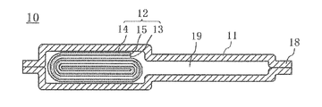
- FIG. 1 is a plan view of a laminated nonaqueous electrolyte secondary battery used in Experimental Example 1.
- FIG. FIG. 2 is a sectional view taken along line II-II in FIG.
- Lithium cobalt composite oxide (LiCoO 2 ) as a positive electrode active material comprises lithium carbonate (Li 2 CO 3 ) as a lithium source and cobalt carbonate (CoCO 3 ) as a cobalt source in a molar ratio of Li: Co.
- the mixture was mixed in a mortar so as to be 1: 1 and then heat-treated in an air atmosphere at 950 ° C. for 10 hours to obtain a powder having an average particle diameter of 17 ⁇ m by pulverization.
- NMP N-methyl-2-pyrrolidone
- positive electrode active material powder prepared as described above
- PVdF Polyvinylidene fluoride
- a material mixture slurry was prepared.
- the above positive electrode active material electrode mixture slurry was coated on both sides of an aluminum foil (thickness 15 ⁇ m, length 340 mm, width 50 mm) as a positive electrode current collector, and the length of the coating part was 280 mm on the front side and 205 mm on the back side.
- the coating part was applied so that both widths were 50 mm, and NMP was dried and removed, followed by rolling to form a positive electrode active material mixture layer on both surfaces of the positive electrode current collector.
- the amount of the positive electrode active material mixture layer on the positive electrode current collector was 48 mg / cm 2 and the thickness was 148 ⁇ m.
- an aluminum plate was connected as a positive electrode current collector tab to the uncoated portion of the positive electrode active material mixture layer at the end of the positive electrode current collector.
- ethyl acrylate-acrylonitrile copolymer as a binder is dispersed in water, and then aluminum oxide (AKP3000 (trade name)) is mixed with erbium oxide in a mass ratio of 500: 11 (this ratio is a rare earth compound contained in the inorganic particle layer).
- the ratio is 3.6% by mass with respect to all elements excluding non-metallic elements in terms of rare earth elements) and further dispersed.
- the positive electrode plate on which the positive electrode active material mixture layer is formed is immersed in the obtained dispersion and dried to mix aluminum oxide and erbium oxide as a rare earth compound on the surface of the positive electrode active material mixture layer. What formed the inorganic particle layer (the thickness per one side is 4 micrometers) was made into the positive electrode plate.
- a polycrystalline silicon lump was produced by a thermal reduction method. Specifically, a silicon core installed in a metal reaction furnace (reduction furnace) is heated by heating to 800 ° C., and purified high-purity monosilane (SiH 4 ) gas vapor and purification are added thereto. By flowing a mixed gas with hydrogen, polycrystalline silicon was deposited on the surface of the silicon core to produce a polycrystalline silicon lump produced in a thick rod shape.
- the polycrystalline silicon lump was pulverized and classified to obtain polycrystalline silicon particles having a purity of 99% as a negative electrode active material.
- the polycrystalline silicon particles had a crystallite size of 32 nm and a median diameter of 10 ⁇ m.
- the crystallite size was calculated by the Scherrer equation using the half width of the silicon (111) peak in powder X-ray diffraction.
- the median diameter was defined as the diameter at which the cumulative volume reached 50% in the particle size distribution measurement by the laser diffraction method.
- thermoplastic polyimide resin As a negative electrode binder, a polyimide resin having a molecular structure represented by the following formula (1) was used. This polyimide resin has thermoplasticity, and its glass transition temperature is 300 ° C. (Hereafter, this polyimide resin is called "thermoplastic polyimide resin")
- thermoplastic polyimide resin precursor varnish a varnish in which NMP was dissolved.
- the polyamic acid generates a polyimide resin by an imidization (dehydration / condensation) reaction by heat treatment at 400 ° C.
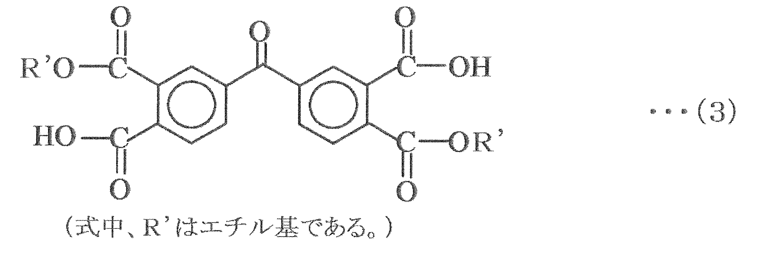
- the polyamic acid according to each experimental example includes 3,3 ′, 4,4′-benzophenone tetracarboxylic acid diethyl ester represented by the following chemical formulas (2), (3) and (4), and the following chemical formula (5): It can be obtained by polymerizing equimolar amounts of the indicated m-phenylenediamine.
- thermoplastic polyimide resin precursor varnish comprises 3,3 ′, 4,4′-benzophenonetetracarboxylic acid diethyl ester (the above chemical formulas (2) to (4)) and m-phenylenediamine (the above chemical formula (5)). It was prepared by dissolving in NMP as a solvent at an equimolar ratio. 3,3 ′, 4,4′-Benzophenonetetracarboxylic acid diethyl ester and m-phenylenediamine are polymerized in NMP solvent to give polyamic acid. The dissolution concentration was 47% by mass in terms of polyimide resin after imidization.
- NMP as a dispersion medium, 89.5 parts by mass of the negative electrode active material, 3.7 parts by mass of graphite powder having an average particle size of 3.5 ⁇ m as a negative electrode conductive material, and 14.5 parts of the thermoplastic polyimide resin precursor varnish.
- the negative electrode active material mixture slurry was prepared by adding and knead
- Negative Electrode Active Material Mixture Layer As a negative electrode current collector, a copper alloy foil having a thickness of 18 ⁇ m (C7025 alloy foil. Composition: Cu: 96.2 mass%, Ni: 3 mass%, Si: 0 .65 mass%, Mg: 0.15 mass%), the surface roughness Ra (JIS B 0601-1994) is 0.25 ⁇ m, and the average peak spacing S (JIS B 0601-1994) is 1.0 ⁇ m. Thus, the electrolytic copper roughened one was used.
- the negative electrode active material mixture slurry was applied to both surfaces of the negative electrode current collector at 25 ° C. in an air atmosphere, dried at 120 ° C., and then rolled at 25 ° C.
- the negative electrode current collector coated with and rolled with the negative electrode active material mixture slurry was cut out into a rectangle having a length of 320 mm and a width of 52 mm, and then heat-treated at 400 ° C. for 10 hours under an argon atmosphere.
- the polyimide acid in the negative electrode active material mixture slurry applied to the surface of the negative electrode current collector was imidized (dehydrated / condensed) to form a negative electrode active material mixture layer on the surface of the negative electrode current collector.
- the amount of the negative electrode active material mixture layer on the negative electrode current collector was 5.6 mg / cm 2 , and the thickness of the negative electrode was 56 ⁇ m. Then, the negative electrode plate was produced by connecting the nickel plate as a negative electrode current collection tab to the edge part of a negative electrode collector.
- Electrode body One positive electrode plate, one negative electrode plate, polyethylene microporous membrane (thickness 20 ⁇ m, length 420 mm, width 54.5 mm, piercing strength 340 g, porosity 39%) Two separators were used, and the positive electrode plate and the negative electrode plate were opposed to each other via the separator. Next, it was wound in a spiral shape using a winding core having a diameter of 18 mm. At this time, both the positive electrode tab and the negative electrode tab were arranged so as to be located on the outermost peripheral portion in each electrode. Thereafter, the wound core was pulled out to produce a wound electrode body, and this wound electrode body was further crushed to produce a flat wound electrode body.
- non-aqueous electrolyte fluoroethylene carbonate (FEC) and methyl ethyl carbonate (MEC) are mixed in a non-aqueous solvent mixed at 20:80 (1 atm, volume ratio at 25 ° C.) as an electrolyte salt.
- FEC fluoroethylene carbonate
- MEC methyl ethyl carbonate
- an electrolyte salt As the non-aqueous electrolyte, fluoroethylene carbonate (FEC) and methyl ethyl carbonate (MEC) are mixed in a non-aqueous solvent mixed at 20:80 (1 atm, volume ratio at 25 ° C.) as an electrolyte salt.
- LiPF 6 lithium hexafluorophosphate
- carbon dioxide gas is dissolved in this solution to a concentration of 0.4% by mass to prepare a non-aqueous electrolyte.
- a nylon layer is disposed on one surface of a metal layer made of aluminum in a CO 2 atmosphere at 25 ° C. and 1 atm, and a polypropylene layer is disposed on the other surface of the flat wound electrode body and the non-aqueous electrolyte.
- the outer package was sealed to produce a nonaqueous electrolyte secondary battery according to Experimental Example 1.
- the design capacity when the nonaqueous electrolyte secondary battery according to Experimental Example 1 is charged until the battery voltage reaches 4.35 V (the positive electrode potential is 4.5 V based on lithium) is 850 mAh.
- the nonaqueous electrolyte secondary battery 10 includes a laminate outer body 11 that covers the outer periphery, a flat wound electrode body 12, and a nonaqueous electrolyte.
- the wound electrode body 12 has a configuration in which a positive electrode plate 13 having an inorganic particle layer (not shown) formed on the surface and a negative electrode plate 14 are wound in a flat shape in a state of being insulated from each other via a separator 15. have.
- a positive electrode current collecting tab 16 is connected to the positive electrode plate 13 of the wound electrode body 12, and a negative electrode current collecting tab 17 is also connected to the negative electrode plate 14.
- the wound electrode body 12 is enclosed with a nonaqueous electrolyte inside a laminate outer body 11 covering the outer periphery, and the outer peripheral edge of the laminate outer body 11 is sealed by a heat seal portion 18.
- the extending portion of the laminate outer package 11 formed to facilitate injection of the nonaqueous electrolyte into one of the side sides of the wound electrode body 12. 19 is left.
- the extending portion 19 is used for analysis of gas components generated during charging / discharging and components formed in the non-aqueous electrolyte.
- FIG. 1 may be heat-sealed at a position along the line AA in FIG.
- Example 2 As the rare earth element compound, yttrium oxide is used instead of erbium oxide, and the mass ratio of the rare earth element compound to aluminum oxide (AKP3000) and yttrium oxide is 500: 7 (this ratio is equivalent to that of yttrium oxide contained in the inorganic particle layer).
- a battery was fabricated in the same manner as in Experimental Example 1 except that the ratio was 2.1% by mass with respect to the total amount of all elements excluding nonmetallic elements in terms of rare earth elements.
- the rare earth element compound lanthanum oxide is used instead of erbium oxide, and the rare earth element compound content is set to 500: 9 (a ratio of aluminum oxide (AKP3000) to lanthanum oxide).
- a battery was fabricated in the same manner as in Experimental Example 1 except that the ratio was 2.9% by mass with respect to the total amount of all elements excluding nonmetallic elements in terms of rare earth elements.
- neodymium oxide is used, and the content of the rare earth element compound is such that the mass ratio of aluminum oxide (AKP3000) to neodymium oxide is 500: 10 (this ratio is the ratio of neodymium oxide contained in the inorganic particle layer).
- a battery was fabricated in the same manner as in Experimental Example 1 except that the ratio was 3.2% by mass with respect to the total amount of all elements excluding nonmetallic elements in terms of rare earth elements.
- Example 5 A battery was fabricated in the same manner as in Experimental Example 1 except that when forming the inorganic particle layer, the rare earth element compound was not used and the inorganic particle layer was formed using only aluminum oxide (AKP3000) as the inorganic particles. .
- Capacity maintenance rate (%) (Discharge capacity at 40th cycle / Discharge capacity at 1st cycle) x 100
- the batteries of Experimental Examples 1 to 4 in which the inorganic particle layer formed on the surface of the positive electrode active material mixture layer contains a rare earth element compound are formed on the surface of the positive electrode active material mixture layer. It can be confirmed that the cycle characteristics in the high temperature environment are improved with respect to the battery of Experimental Example 5 in which the inorganic particle layer does not contain the rare earth element compound.
- the effect of improving the high-temperature cycle characteristics is that the decomposition product generated by the decomposition of the electrolyte solution on the positive electrode side moves to the negative electrode, or the decomposition product generated by the decomposition of the electrolyte solution on the negative electrode side moves to the positive electrode.
- the presence of the rare earth element compound in the inorganic particle layer is achieved by effectively trapping (adsorbing) the decomposition products.
- the rare earth element compound-containing inorganic particle layer is present at a position where the movement of the electrolyte decomposition product can be suppressed, the above effect is considered to be achieved. Therefore, in Experimental Examples 1 to 4, the nonaqueous electrolyte secondary battery in which the rare earth element compound-containing inorganic particle layer was formed only on the positive electrode side was used, but the rare earth element compound-containing inorganic particle layer was used as the negative electrode active material mixture layer. It may be formed only on the surface, or may be formed on both the positive electrode side and the negative electrode side.
- the present invention can be implemented regardless of the composition of the water electrolyte and the type of rare earth element compound.
- the amount of the negative electrode active material mixture layer on the negative electrode current collector was 23 mg / cm 2 , and the thickness of the negative electrode was 154 ⁇ m. Then, the negative electrode plate was produced by connecting the nickel plate as a negative electrode current collection tab to the edge part of a negative electrode collector.
- Non-aqueous electrolyte lithium hexafluorophosphate (LiPF 6 ) as an electrolyte was mixed with a non-aqueous solvent in which ethylene carbonate (EC) and diethyl carbonate (DEC) were mixed at a volume ratio of 3: 7. Was dissolved to a concentration of 1.2 mol / L. Furthermore, vinylene carbonate (VC) was added in an amount of 2.0% by mass based on the total amount of the non-aqueous electrolyte, and dissolved to prepare a non-aqueous electrolyte.
- EC ethylene carbonate
- DEC diethyl carbonate
- VC vinylene carbonate
- the content of the rare earth element compound is such that the mass ratio of aluminum oxide (AKP3000) to erbium oxide is 25:75 (this ratio is the ratio of erbium oxide contained in the inorganic particle layer except for nonmetallic elements in terms of rare earth elements).
- a battery was fabricated in the same manner as in Experimental Example 6 except that the amount was 83.2% by mass with respect to the total amount of elements.
- the content of the rare earth element compound is 50:50 by mass ratio of aluminum oxide (AKP3000) and erbium oxide (this ratio is the ratio of erbium oxide contained in the inorganic particle layer except for nonmetallic elements in terms of rare earth elements).
- a battery was fabricated in the same manner as in Experimental Example 6 except that the content was 62.3 mass% with respect to the total amount of elements.
- the content of the rare earth element compound is such that the mass ratio of aluminum oxide (AKP3000) to erbium oxide is 75:25 (this ratio is the ratio of the erbium oxide contained in the inorganic particle layer except for nonmetallic elements in terms of rare earth elements).
- a battery was fabricated in the same manner as in Experimental Example 6 except that the total amount of elements was 35.5% by mass.
- the content of the rare earth element compound is such that the mass ratio of aluminum oxide (AKP3000) to erbium oxide is 95: 5 (this ratio is the ratio of the erbium oxide contained in the inorganic particle layer to all elements excluding nonmetallic elements in terms of rare earth elements)
- a battery was fabricated in the same manner as in Experimental Example 6 except that the total amount of elements was 8.0% by mass.
- the content of the rare earth element compound is such that the mass ratio of aluminum oxide (AKP3000) to erbium oxide is 99: 1 (this ratio is the ratio of the erbium oxide contained in the inorganic particle layer to all the elements other than nonmetallic elements in terms of rare earth elements).
- a battery was fabricated in the same manner as in Experimental Example 6 except that the amount was 1.6% by mass with respect to the total amount of elements.
- Example 12 A battery was fabricated in the same manner as in Experimental Example 6 except that when forming the inorganic particle layer, the inorganic particle layer was formed using only aluminum oxide (AKP3000) as the inorganic particles without using the rare earth element compound. .
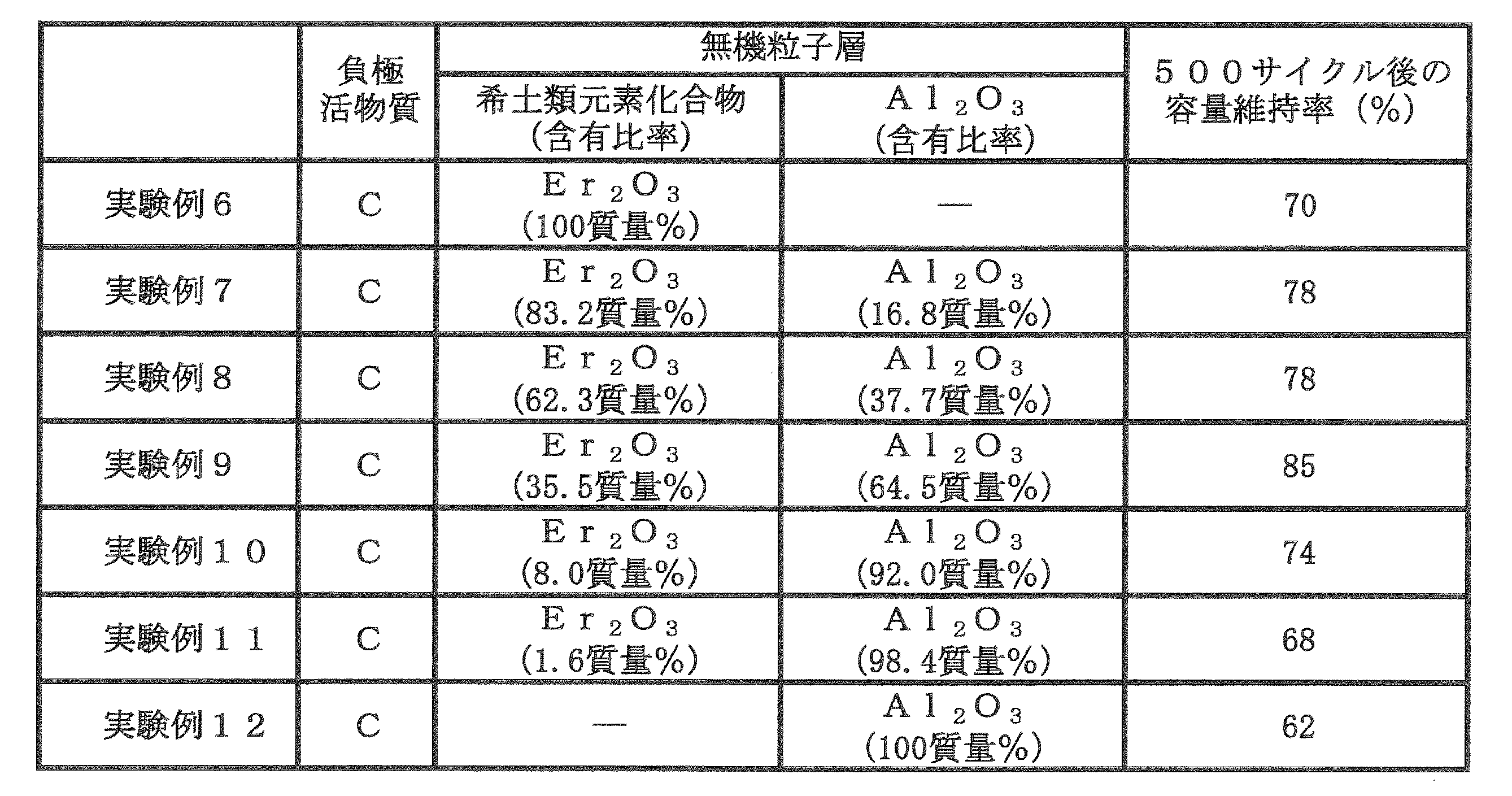
- Capacity maintenance rate (%) (Discharge capacity at 500th cycle / discharge capacity at the first cycle) x 100
- the inorganic material formed on the surface of the positive electrode active material mixture layer was the same as in the first experimental example using Si as the negative electrode active material.
- the batteries of Experimental Examples 6 to 11 containing the rare earth element compound in the particle layer are higher in temperature than the battery of Experimental Example 12 in which the inorganic particle layer formed on the surface of the positive electrode active material mixture layer does not contain the rare earth element compound. It can be confirmed that the cycle characteristics in the environment are improved.
- the improvement effect of the high-temperature cycle characteristics is that the decomposition product generated by the decomposition of the electrolyte solution on the positive electrode side moves to the negative electrode, or the electrolyte solution is decomposed on the negative electrode side.
- the decomposed product produced in this way moves to the positive electrode, it is presumed that the decomposition product is effectively trapped (adsorbed) due to the presence of the rare earth element compound in the inorganic particle layer.
- the batteries of Experimental Examples 7 to 10 using the inorganic particle layer containing aluminum oxide and erbium oxide as inorganic particles in a predetermined ratio on the surface of the positive electrode active material mixture layer Is a battery of Experimental Example 6 containing only erbium oxide as inorganic particles, a battery of Experimental Example 12 containing only aluminum oxide as inorganic particles, and containing both aluminum oxide and erbium oxide as inorganic particles.
- the cycle characteristics in the high temperature environment are specifically improved as compared with the battery of Experimental Example 11 in which the content of erbium oxide is smaller than those of the above Experimental Examples 7 to 10.
- the capacity retention rates in the batteries of Experimental Examples 7 to 10 do not exist within the range of the capacity maintenance ratios of the batteries of Experimental Examples 6 and 12, but exist beyond the range.
- the battery of Experimental Example 6 is 70% and the battery of Experimental Example 12 is 62% by mass. Therefore, an inorganic particle layer containing the erbium oxide of Experimental Example 6 and the aluminum oxide of Experimental Example 12 is used.
- the capacity maintenance rate is assumed to be between 62% and 70%, but actually it is 74% or more, and it can be seen that the improvement exceeds the expected range. .
- the content of the rare earth element compound to be included in the inorganic particle layer is a rare earth element conversion with respect to the total amount of all the remaining elements excluding nonmetallic elements from all elements constituting the inorganic particle layer. It can be seen that the content is preferably 1% by mass or more and 100% by mass or less. This is because if the content of the rare earth element compound contained in the inorganic particle layer is too small, the above effect cannot be obtained sufficiently. Moreover, it turns out that it is more preferable to set it as 1 mass% or more and 85 mass% or less from a viewpoint of a capacity
- the above experimental results are considered to be due to the following reasons. Considering the above effect (the presence of the rare earth element compound in the inorganic particle layer effectively traps the decomposition product of the electrolytic solution generated on the positive electrode side or the negative electrode side). It is considered that the use of only the rare earth compound in the particle layer is more effective and can further suppress the decrease in capacity retention rate.
- the inorganic particle layer is prepared so that the mass of the inorganic particle layer is the same, and erbium oxide has a heavier weight per mol than aluminum oxide, so that the inorganic particle layer contains only erbium oxide. Is thinner than the inorganic particle layer containing aluminum oxide. As a result, it is presumed that the above effect was not sufficiently obtained and the effect of suppressing the decrease in the capacity retention rate was reduced compared to the batteries of Experimental Examples 7 to 10.
- the negative electrode active material is a Si-containing negative electrode active material than when a negative electrode active material containing a carbon material is used. It can be seen that the effect of improving the cycle characteristics is greater when used. Therefore, it is more preferable to use a negative electrode active material containing Si as the negative electrode active material.
- the content is 2% by mass or more, particularly 5% by mass or more, the influence becomes large.
- an inorganic particle layer containing a rare earth element compound is applied to the positive electrode or the negative electrode, deterioration at the time of cycling at high temperature is caused. Further suppression is possible.
- rare earth elements constituting rare earth element compounds include yttrium, lanthanum, cerium, praseodymium, neodymium, samarium, europium, gadolinium, terbium, dysprosium, holmium, erbium, thulium, ytterbium, lutetium and scandium.
- praseodymium, neodymium, samarium, europium, gadolinium, terbium, dysprosium, holmium, erbium, thulium, ytterbium, lutetium, and scandium are preferable, and neodymium or erbium is particularly preferable.
- These rare earth elements may be one kind or a mixture of two or more kinds.
- a misch metal compound which is a mixture of rare earth elements can also be used.
- These rare earth element compounds include oxides, hydroxides, oxyhydroxides, carbonic acid compounds, phosphoric acid compounds, nitric acid compounds, sulfuric acid compounds, acetic acid compounds, oxalic acid compounds, fluorides, alone or in combination of two or more. It can be used as a mixture.
- oxides, hydroxides, oxyhydroxides, phosphoric acid compounds, and fluorides are particularly preferably used because they have a high effect of trapping decomposition products of the electrolytic solution.
- the inorganic particle layer preferably contains other inorganic particles in addition to the rare earth element compound.
- known particles can be used.
- titanium, aluminum, silicon, magnesium, zirconium, molybdenum, tungsten, etc. are used alone or in combination with an oxide or phosphate compound, and the surface is treated with hydroxide. What is being done is mentioned.
- titanium, aluminum, silicon, and magnesium are particularly preferable. This is because titanium, aluminum, silicon, and magnesium can not only spread inorganic particles of rare earth compounds in the entire surface direction of the electrode plate but also in the thickness direction in a small amount compared to zirconium, molybdenum, tungsten, etc. Because it is.
- the thickness of the inorganic particle layer is preferably 1 ⁇ m or more and 25 ⁇ m or less. This is because if the thickness is too thick, the volume occupied by the substance that does not contribute to the charge / discharge reaction is excessive, and the capacity of the battery may not be increased. If the thickness is too thin, the effect of trapping the decomposition product of the electrolyte cannot be obtained sufficiently. Because there is a fear.
- lithium cobalt composite oxide lithium composite oxide of Ni—Co—Mn, Ni -Min-Al lithium composite oxide, Ni-Co-Al composite oxide, Ni-Mn lithium composite oxide, olivine-type transition metal oxide containing iron, manganese, etc.
- LiMPO 4 M May be selected from Fe, Mn, Co, and Ni
- the lithium-containing transition metal composite oxide may contain a substance such as Al, Mg, Ti, Zr or the like, or may be contained in the grain boundary.
- the Ni—Co—Mn lithium composite oxide the molar ratio of Ni, Co, and Mn is 1: 1: 1, 5: 3: 2, 5: 2: 3, 6:
- Known compositions such as 2: 2, 7: 1: 2, 7: 2: 1, and 8: 1: 1 can be used.
- the positive electrode capacity can be increased. Therefore, it is preferable to use a material having a higher proportion of Ni or Co than Mn.
- the positive electrode active materials may be of the same particle diameter or of different particle diameters. Good.
- the positive electrode active material mixture layer preferably contains a compound containing at least one element selected from the group consisting of rare earth, zirconium, aluminum, magnesium, titanium, tungsten, niobium, and tantalum, A compound containing at least one element selected from the group consisting of rare earth, zirconium, aluminum, magnesium, titanium, tungsten, niobium, and tantalum adheres to the particle surface of the lithium transition metal composite oxide as the positive electrode active material. It is desirable.
- non-aqueous electrolyte solvent can be used as the non-aqueous electrolyte solvent.
- cyclic carbonates such as ethylene carbonate, propylene carbonate, butylene carbonate, vinylene carbonate, chain carbonates such as dimethyl carbonate, methyl ethyl carbonate, diethyl carbonate, methyl acetate, ethyl acetate, propyl acetate, methyl propionate, propionic acid
- esters such as ethyl and ⁇ -butyrolactone
- compounds containing sulfone groups such as propane sultone, 1,2-dimethoxyethane, 1,2-diethoxyethane, tetrahydrofuran, 1,3-dioxane, 1,4 -Compounds containing ethers such as dioxane and 2-methyltetrahydrofuran, butyronitrile, valeronitrile, n-heptanenitrile, succinonitrile, gluta
- a solvent in which a part of hydrogen of these compounds is substituted with fluorine is preferably used.
- these can be used alone or in combination, and a solvent in which a cyclic carbonate and a chain carbonate are combined, and a solvent in which a compound containing a small amount of nitrile or a compound containing ether is further combined is preferable. .
- solute of the nonaqueous electrolytic solution a conventionally used solute can be used, and LiPF 6 , LiBF 4 , LiN (SO 2 F) 2 , LiN (SO 2 CF 3 ) 2 , LiN (SO 2 C).
- LiPF 6-x (C n F 2n-1 ) x [where 1 ⁇ x ⁇ 6, n 1 or 2], etc., as well as lithium salts having an oxalato complex as an anion
- the Lithium salts having an oxalato complex as an anion include LiBOB [lithium-bisoxalate borate] and lithium salts having an anion in which C 2 O 4 2 ⁇ is coordinated to the central atom, for example, Li [M (C 2 O 4 ) x R y ] (wherein M is a transition metal, an element selected from groups IIIb, IVb, and Vb of the periodic table, R is selected from a halogen, an alkyl group, and a halogen-substituted alkyl group) Group, x is a positive integer, and y is 0 or a positive integer).
- Li [B (C 2 O 4 ) F 2 ] Li [P (C 2 O 4 ) F 4 ]
- Li [P (C 2 O 4 ) 2 F 2 ] and the like.
- LiBOB Li [B (C 2 O 4 ) F 2 ]
- the above solutes may be used alone or in combination of two or more.
- the concentration of the solute is not particularly limited, but is preferably 0.8 to 1.7 mol per liter of the electrolyte.
- separator conventionally used separators can be used. Specifically, not only a separator made of polyethylene, but also a material in which a layer made of polypropylene is formed on the surface of a polyethylene layer, or a material in which a resin such as an aramid resin is applied to the surface of a polyethylene separator is used. Also good.
- silicon and carbon materials were used as the negative electrode active material.
- conventionally used negative electrode active materials can be used, for example, carbon capable of occluding and releasing lithium. Examples thereof include a material, a metal capable of forming an alloy with lithium, or an alloy compound containing the metal.
- the carbon material as the negative electrode active material graphite such as natural graphite, non-graphitizable carbon, artificial graphite, and coke can be used, and the alloy compound includes at least a metal that can be alloyed with lithium.
- the alloy compound includes at least a metal that can be alloyed with lithium.
- silicon or tin is preferable as an element capable of forming an alloy with lithium, and silicon oxide, tin oxide, or the like in which these are combined with oxygen can also be used.
- what mixed the said carbon material and the compound of silicon or tin can be used.
- a negative electrode active material having a higher charge / discharge potential for metal lithium such as lithium titanate than a carbon material can be used.
- silicon oxide SiO x (0 ⁇ x ⁇ 2, particularly preferably 0 ⁇ x ⁇ 1)] may be used.
Landscapes
- Chemical & Material Sciences (AREA)
- Chemical Kinetics & Catalysis (AREA)
- Electrochemistry (AREA)
- General Chemical & Material Sciences (AREA)
- Composite Materials (AREA)
- Inorganic Chemistry (AREA)
- Engineering & Computer Science (AREA)
- Materials Engineering (AREA)
- Condensed Matter Physics & Semiconductors (AREA)
- General Physics & Mathematics (AREA)
- Physics & Mathematics (AREA)
- Manufacturing & Machinery (AREA)
- Secondary Cells (AREA)
- Battery Electrode And Active Subsutance (AREA)
Abstract
Description
[実験例1]
(正極極板の作製)
正極活物質としてのリチウムコバルト複合酸化物(LiCoO2)は、リチウム源としての炭酸リチウム(Li2CO3)と、コバルト源としての炭酸コバルト(CoCO3)とを、Li:Coがモル比で1:1となるようにして乳鉢で混合した後、空気雰囲気下、950℃、10時間の条件で熱処理したものを、粉砕して平均粒子径17μmの粉末とすることによって得た。
(1)ケイ素負極活物質の調製
先ず、熱還元法により多結晶ケイ素塊を作製した。具体的には、金属反応炉(還元炉)内に設置されたケイ素芯を通電加熱して800℃まで上昇させておき、これに、精製された高純度モノシラン(SiH4)ガスの蒸気と精製された水素との混合ガスを流すことでケイ素芯の表面に多結晶ケイ素を析出させて、太い棒状に生成された多結晶ケイ素塊を作製した。
負極バインダーとしては、下記式(1)で示される分子構造を有するポリイミド樹脂を用いた。このポリイミド樹脂は熱可塑性を有しており、ガラス転移温度は300℃である。(以下、このポリイミド樹脂を「熱可塑性ポリイミド樹脂」という)




負極集電体としては、厚さ18μmの銅合金箔(C7025合金箔。組成は、Cu:96.2質量%、Ni:3質量%、Si:0.65質量%、Mg:0.15質量%)の両面を、表面粗さRa(JIS B 0601-1994)が0.25μm、平均山間隔S(JIS B 0601-1994)が1.0μmとなるように電解銅粗化したものを用いた。
上記正極極板を1枚、上記負極極板を1枚、ポリエチレン製微多孔膜(厚さ20μm、長さ420mm、幅54.5mmであって、突き刺し強度340g、空孔率39%)からなるセパレータを2枚用いて、正極極板と負極極板とをセパレータを介して互いに対向させた。次に、直径18mmの巻き芯を用いて、渦巻き状に巻回した。この際、正極タブ及び負極タブは、共に、各電極内における最外周部に位置するように配置した。その後、巻き芯を引き抜いて巻回電極体を作製し、更にこの巻回電極体を押し潰して偏平形の巻回電極体を作製した。
非水電解液としては、フルオロエチレンカーボネート(FEC)、メチルエチルカーボネート(MEC)を、20:80(1気圧、25℃での体積比)となるよう混合した非水溶媒に、電解質塩としてのヘキサフルオロリン酸リチウム(LiPF6)を1mol/Lとなるように溶解させた後、この溶液に対して二酸化炭素ガスを0.4質量%の濃度となるように溶解させて非水電解液を調製した。
上記偏平形の巻回電極体及び上記非水電解液を、25℃、1気圧のCO2雰囲気下でアルミニウムからなる金属層の一方の面にナイロン層、他方の面にポリプロピレン層が配されたアルミニウムラミネート製の外装体に挿入した後、外装体を封止することで、実験例1に係る非水電解質二次電池を作製した。実験例1に係る非水電解質二次電池を電池電圧が4.35V(リチウム基準で正極電位が4.5V)となるまで充電した場合の設計容量は、850mAhである。
ここで実験例1で作製したラミネート形の非水電解質二次電池10の構成について、図1及び図2を用いて説明する。非水電解質二次電池10は、外周囲を覆うラミネート外装体11と、偏平状の巻回電極体12と、非水電解液とを備えている。巻回電極体12は、表面に無機粒子層(図示省略)が形成された正極板13と、負極板14と、がセパレータ15を介して互いに絶縁された状態で偏平状に巻回された構成を有している。巻回電極体12の正極板13には正極集電タブ16が接続され、同じく負極板14には接続された負極集電タブ17が接続されている。巻回電極体12は、外周囲を覆うラミネート外装体11の内部に非水電解液とともに封入されており、ラミネート外装体11の外周縁端部はヒートシール部18により密封されている。
希土類元素化合物として酸化エルビウムに代えて酸化イットリウムを用い、希土類元素化合物の含有量を、酸化アルミニウム(AKP3000)と酸化イットリウムの質量比が500:7(この比率は無機粒子層に含まれる酸化イットリウムの比率が、希土類元素換算で非金属元素を除く全ての元素の総量に対して2.1質量%となる)となるようにしたこと以外は、上記実験例1と同様にして電池を作製した。
希土類元素化合物として酸化エルビウムに代えて酸化ランタンを用い、希土類元素化合物の含有量を、酸化アルミニウム(AKP3000)と酸化ランタンの質量比が500:9(この比率は無機粒子層に含まれる酸化ランタンの比率が、希土類元素換算で非金属元素を除く全ての元素の総量に対して2.9質量%となる)となるようにしたこと以外は、上記実験例1と同様にして電池を作製した。
希土類元素化合物として酸化エルビウムに代えて酸化ネオジムを用い、希土類元素化合物の含有量を、酸化アルミニウム(AKP3000)と酸化ネオジムの質量比が500:10(この比率は無機粒子層に含まれる酸化ネオジムの比率が、希土類元素換算で非金属元素を除く全ての元素の総量に対して3.2質量%となる)となるようにしたこと以外は、上記実験例1と同様にして電池を作製した。
無機粒子層を形成する際に、希土類元素化合物を用いず、無機粒子として酸化アルミニウム(AKP3000)のみを用いて無機粒子層を形成したこと以外は、上記実験例1と同様にして電池を作製した。
上記のようにして得られた実験例1~5の各非水電解質二次電池について、下記(A)の条件にて25℃で初期充放電(1サイクル目の充放電)を行った後、下記(B)の条件にて45℃で充放電(2サイクル目以降の充放電)を繰り返し行った。
(A) 1サイクル目の充放電
温度:25℃
充電条件:43mAの電流で1時間定電流充電を行った後、1It(=850mA)の定電流で電池電圧が4.35Vとなるまで充電を行い、電池電圧が4.35Vに達した後は4.35Vの定電圧で電流値が1/20It(=43mA)となるまで充電を行った。
放電条件:1It(=850mA)の定電流で電池電圧が2.75Vとなるまで放電を行った。
(B) 2~40サイクル目の充放電
温度:45℃
充電条件:1It(=850mA)の電流で電池電圧が4.35Vとなるまで定電流充電を行い、電池電圧が4.35Vに達した後は4.35Vの定電圧で電流値が1/20It(=43mA)となるまで定電圧充電を行った。
放電条件:1It(=850mA)の定電流で電池電圧が2.75Vとなるまで放電を行った。
容量維持率(%)
= (40サイクル目の放電容量/1サイクル目の放電容量)×100

[実験例6]
(正極極板の作製)
無機粒子層を形成する際に、酸化アルミニウムを用いず、無機粒子として酸化エルビウムのみを用いて無機粒子層を形成したこと以外は、上記実験例1と同様にして正極極板を作製した。
増粘剤としてのCMC(カルボキシメチルセルロースナトリウム)を水に溶解した水溶液中に、負極活物質としての人造黒鉛と、結着剤としてのSBR(スチレン-ブタジエンゴム)とを、負極活物質と結着剤と増粘剤の質量比が98:1:1の比率になるようにして加えて混練することで、負極活物質合剤スラリーを作製した。この負極活物質合剤スラリーを、銅箔からなる負極集電体の両面にできるだけ均一に塗布し、乾燥させた後、圧延ローラにより圧延し、負極集電体の表面に負極活物質合剤層を形成した。上記負極集電体上の負極活物質合剤層の量は23mg/cm2で、負極の厚みは154μmであった。その後、負極集電体の端部に負極集電タブとしてのニッケル板を接続することで、負極極板を作製した。
非水電解液としては、エチレンカーボネート(EC)とジエチルカーボネート(DEC)とを、3:7の体積比となるように混合した非水溶媒に、電解質としてのヘキサフルオロリン酸リチウム(LiPF6)を1.2mol/Lの濃度となるように溶解した。さらに、ビニレンカーボネート(VC)を非水電解液全量に対して2.0質量%添加し、溶解させて非水電解液を調整した。
上記正極極板、上記負極極板、上記非水電解液を用いたこと以外は、上記実験例1と同様にして電池を作製した。実験例6で作製した非水電解質二次電池の構成は、上記実験例1の構成と同様であった。なお、この電池を電池電圧が4.4V(リチウム基準で正極電位が4.5V)となるまで充電した場合の設計容量は、850mAhである。
希土類元素化合物の含有量を、酸化アルミニウム(AKP3000)と酸化エルビウムの質量比が25:75(この比率は無機粒子層に含まれる酸化エルビウムの比率が、希土類元素換算で非金属元素を除く全ての元素の総量に対して83.2質量%となる)となるようにしたこと以外は、上記実験例6と同様にして電池を作製した。
希土類元素化合物の含有量を、酸化アルミニウム(AKP3000)と酸化エルビウムの質量比が50:50(この比率は無機粒子層に含まれる酸化エルビウムの比率が、希土類元素換算で非金属元素を除く全ての元素の総量に対して62.3質量%となる)となるようにしたこと以外は、上記実験例6と同様にして電池を作製した。
希土類元素化合物の含有量を、酸化アルミニウム(AKP3000)と酸化エルビウムの質量比が75:25(この比率は無機粒子層に含まれる酸化エルビウムの比率が、希土類元素換算で非金属元素を除く全ての元素の総量に対して35.5質量%となる)となるようにしたこと以外は、上記実験例6と同様にして電池を作製した。
希土類元素化合物の含有量を、酸化アルミニウム(AKP3000)と酸化エルビウムの質量比が95:5(この比率は無機粒子層に含まれる酸化エルビウムの比率が、希土類元素換算で非金属元素を除く全ての元素の総量に対して8.0質量%となる)となるようにしたこと以外は、上記実験例6と同様にして電池を作製した。
希土類元素化合物の含有量を、酸化アルミニウム(AKP3000)と酸化エルビウムの質量比が99:1(この比率は無機粒子層に含まれる酸化エルビウムの比率が、希土類元素換算で非金属元素を除く全ての元素の総量に対して1.6質量%となる)となるようにしたこと以外は、上記実験例6と同様にして電池を作製した。
無機粒子層を形成する際に、希土類元素化合物を用いず、無機粒子として酸化アルミニウム(AKP3000)のみを用いて無機粒子層を形成したこと以外は、上記実験例6と同様にして電池を作製した。
上記のようにして得られた実験例6~12の各非水電解質二次電池について、下記(C)の条件にて25℃で初期充放電(1サイクル目の充放電)を行った後、下記(D)の条件にて45℃で充放電(2サイクル目以降の充放電)を繰り返し行った。
(C) 1サイクル目の充放電
温度:25℃
充電条件:43mAの電流で1時間定電流充電を行った後、1It(=850mA)の定電流で電池電圧が4.4Vとなるまで充電を行い、電池電圧が4.4Vに達した後は4.4Vの定電圧で電流値が1/20It(=43mA)となるまで充電を行った。
放電条件:1It(=850mA)の定電流で電池電圧が2.75Vとなるまで放電を行った。
(D) 2~500サイクル目の充放電
温度:45℃
充電条件:1It(=850mA)の電流で電池電圧が4.4Vとなるまで定電流充電を行い、電池電圧が4.4Vに達した後は4.4Vの定電圧で電流値が1/20It(=43mA)となるまで定電圧充電を行った。
放電条件:1It(=850mA)の定電流で電池電圧が2.75Vとなるまで放電を行った。
容量維持率(%)
= (500サイクル目の放電容量/1サイクル目の放電容量)×100
11 ラミネート外装体
12 巻回電極体
13 正極板
14 負極板
15 セパレータ
16 正極集電タブ
17 負極集電タブ
18 ヒートシール部
19 延在部
Claims (11)
- 正極活物質合剤層が形成された正極と、
負極活物質合剤層が形成された負極と、
非水電解液と、
セパレータとを備え、
前記正極活物質合剤層及び前記負極活物質合剤層の少なくとも一方の表面には、希土類元素化合物を含有する無機粒子層が形成されている非水電解質二次電池。 - 前記無機粒子層中の前記希土類元素化合物の含有量が、前記無機粒子層を構成する元素であって非金属元素ではない元素の総量に対して、希土類元素換算で1質量%以上100質量%以下である、請求項1に記載の非水電解質二次電池。
- 前記無機粒子層中の前記希土類元素化合物の含有量が、1質量%以上85質量%以下である、請求項2に記載の非水電解質二次電池。
- 前記無機粒子層中の前記希土類元素化合物の含有量が、8質量%以上85質量%以下である、請求項2に記載の非水電解質二次電池。
- 前記無機粒子層の厚みが1μm以上25μm以下である、請求項1~4のいずれかに記載の非水電解質二次電池。
- 前記希土類元素化合物を構成する希土類元素は、イットリウム、ランタン、セリウム、プラセオジム、ネオジム、サマリウム、ユーロピウム、ガドリニウム、テルビウム、ディスプロシウム、ホルミウム、エルビウム、ツリウム、イッテルビウム、ルテチウム、スカンジウムから選ばれる少なくとも一種である、請求項1~5のいずれかに記載の非水電解質二次電池。
- 前記希土類元素が、ネオジム、エルビウムから選ばれる少なくとも一種である、請求項6に記載の非水電解質二次電池。
- 前記希土類元素化合物が、水酸化物、オキシ水酸化物、酸化物、リン酸化合物、炭酸化合物から選ばれた少なくとも一種である、請求項1~7のいずれかに記載の非水電解質二次電池。
- 前記無機粒子層は、チタン、アルミニウム、ケイ素、マグネシウム、ジルコニウム、モリブデン、タングステンから選ばれる少なくとも一種の元素の化合物を含有する、請求項1~8のいずれかに記載の非水電解質二次電池。
- 前記無機粒子層は、チタン、アルミニウム、ケイ素、マグネシウムから選ばれる少なくとも一種の元素の化合物を含有する、請求項9に記載の非水電解質二次電池。
- 前記負極は、Siを含む負極活物質を含有する、請求項1~10のいずれかに記載の非水電解質二次電池。
Priority Applications (3)
| Application Number | Priority Date | Filing Date | Title |
|---|---|---|---|
| CN201380046355.8A CN104603991B (zh) | 2012-10-31 | 2013-10-30 | 非水电解质二次电池 |
| US14/423,965 US9478802B2 (en) | 2012-10-31 | 2013-10-30 | Nonaqueous electrolyte secondary battery |
| JP2014544314A JP6208144B2 (ja) | 2012-10-31 | 2013-10-30 | 非水電解質二次電池 |
Applications Claiming Priority (2)
| Application Number | Priority Date | Filing Date | Title |
|---|---|---|---|
| JP2012-240102 | 2012-10-31 | ||
| JP2012240102 | 2012-10-31 |
Publications (1)
| Publication Number | Publication Date |
|---|---|
| WO2014068969A1 true WO2014068969A1 (ja) | 2014-05-08 |
Family
ID=50626917
Family Applications (1)
| Application Number | Title | Priority Date | Filing Date |
|---|---|---|---|
| PCT/JP2013/006417 Ceased WO2014068969A1 (ja) | 2012-10-31 | 2013-10-30 | 非水電解質二次電池 |
Country Status (4)
| Country | Link |
|---|---|
| US (1) | US9478802B2 (ja) |
| JP (1) | JP6208144B2 (ja) |
| CN (1) | CN104603991B (ja) |
| WO (1) | WO2014068969A1 (ja) |
Cited By (1)
| Publication number | Priority date | Publication date | Assignee | Title |
|---|---|---|---|---|
| JPWO2018030148A1 (ja) * | 2016-08-10 | 2019-06-20 | パナソニックIpマネジメント株式会社 | 非水電解質二次電池用正極活物質、非水電解質二次電池用正極、非水電解質二次電池、及び非水電解質二次電池用正極活物質の製造方法 |
Families Citing this family (1)
| Publication number | Priority date | Publication date | Assignee | Title |
|---|---|---|---|---|
| JP6128398B2 (ja) * | 2014-12-26 | 2017-05-17 | トヨタ自動車株式会社 | 非水電解質二次電池 |
Citations (4)
| Publication number | Priority date | Publication date | Assignee | Title |
|---|---|---|---|---|
| JPH08236114A (ja) * | 1995-02-27 | 1996-09-13 | Sanyo Electric Co Ltd | リチウム二次電池 |
| JP2004014134A (ja) * | 2002-06-03 | 2004-01-15 | Mitsubishi Chemicals Corp | 非水系電解液二次電池およびそれに用いる電解液 |
| JP2007134279A (ja) * | 2005-11-14 | 2007-05-31 | Matsushita Electric Ind Co Ltd | 非水電解液二次電池 |
| JP2009211817A (ja) * | 2008-02-29 | 2009-09-17 | Sanyo Electric Co Ltd | 非水電解質二次電池の製造方法 |
Family Cites Families (4)
| Publication number | Priority date | Publication date | Assignee | Title |
|---|---|---|---|---|
| JP4253853B2 (ja) | 1995-06-28 | 2009-04-15 | 宇部興産株式会社 | 非水二次電池 |
| CN100442577C (zh) * | 2003-07-17 | 2008-12-10 | 株式会社杰士汤浅 | 正极活性物质及其制造方法、以及锂二次电池的正极和锂二次电池 |
| US8153295B2 (en) * | 2003-07-17 | 2012-04-10 | Gs Yuasa International Ltd. | Positive electrode active material and its manufacturing method, positive electrode for lithium secondary cell using same, and lithium secondary cell |
| US9437869B2 (en) * | 2010-12-20 | 2016-09-06 | Sanyo Electric Co., Ltd. | Positive electrode for nonaqueous electrolyte secondary battery and nonaqueous electrolyte secondary battery using the positive electrode |
-
2013
- 2013-10-30 JP JP2014544314A patent/JP6208144B2/ja active Active
- 2013-10-30 WO PCT/JP2013/006417 patent/WO2014068969A1/ja not_active Ceased
- 2013-10-30 CN CN201380046355.8A patent/CN104603991B/zh active Active
- 2013-10-30 US US14/423,965 patent/US9478802B2/en active Active
Patent Citations (4)
| Publication number | Priority date | Publication date | Assignee | Title |
|---|---|---|---|---|
| JPH08236114A (ja) * | 1995-02-27 | 1996-09-13 | Sanyo Electric Co Ltd | リチウム二次電池 |
| JP2004014134A (ja) * | 2002-06-03 | 2004-01-15 | Mitsubishi Chemicals Corp | 非水系電解液二次電池およびそれに用いる電解液 |
| JP2007134279A (ja) * | 2005-11-14 | 2007-05-31 | Matsushita Electric Ind Co Ltd | 非水電解液二次電池 |
| JP2009211817A (ja) * | 2008-02-29 | 2009-09-17 | Sanyo Electric Co Ltd | 非水電解質二次電池の製造方法 |
Cited By (1)
| Publication number | Priority date | Publication date | Assignee | Title |
|---|---|---|---|---|
| JPWO2018030148A1 (ja) * | 2016-08-10 | 2019-06-20 | パナソニックIpマネジメント株式会社 | 非水電解質二次電池用正極活物質、非水電解質二次電池用正極、非水電解質二次電池、及び非水電解質二次電池用正極活物質の製造方法 |
Also Published As
| Publication number | Publication date |
|---|---|
| JPWO2014068969A1 (ja) | 2016-09-08 |
| JP6208144B2 (ja) | 2017-10-04 |
| US20150214542A1 (en) | 2015-07-30 |
| US9478802B2 (en) | 2016-10-25 |
| CN104603991A (zh) | 2015-05-06 |
| CN104603991B (zh) | 2017-05-24 |
Similar Documents
| Publication | Publication Date | Title |
|---|---|---|
| KR102633418B1 (ko) | 비수전해질 이차 전지용 부극 활물질 및 비수전해질 이차 전지, 그리고 비수전해질 이차 전지용 부극재의 제조 방법 | |
| JP6589856B2 (ja) | 非水電解質二次電池 | |
| JP5361233B2 (ja) | リチウム二次電池及びその製造方法 | |
| JP6237791B2 (ja) | 非水電解質二次電池用負極 | |
| CN105122514B (zh) | 非水电解质二次电池用正极活性物质及使用其的非水电解质二次电池 | |
| JP6236018B2 (ja) | 偏平形非水電解質二次電池及びそれを用いた組電池 | |
| CN103348516B (zh) | 非水电解液二次电池用正极活性物质、其制造方法、使用该正极活性物质的非水电解液二次电池用正极以及使用该正极的非水电解液二次电池 | |
| JP5931750B2 (ja) | 非水電解液二次電池用正極活物質、その製造方法、当該正極活物質を用いた非水電解液二次電池用正極、及び、当該正極を用いた非水電解液二次電池 | |
| JP6565916B2 (ja) | 非水電解質二次電池 | |
| JP2009099523A (ja) | リチウム二次電池 | |
| JPWO2012099265A1 (ja) | 非水電解質二次電池用正極活物質、その正極活物質を用いた非水電解質二次電池用正極及びその正極を用いた非水電解質二次電池 | |
| JP6288098B2 (ja) | 偏平形非水電解質二次電池及びそれを用いた組電池 | |
| CN102640343A (zh) | 非水电解质二次电池 | |
| WO2012124525A1 (ja) | 非水電解質二次電池及びその製造方法 | |
| JPWO2014068931A1 (ja) | 非水電解質二次電池 | |
| WO2013002369A1 (ja) | 非水電解質二次電池及びその製造方法 | |
| JP2014049287A (ja) | 非水電解質二次電池及び非水電解質二次電池スタック | |
| WO2016021596A1 (ja) | リチウム二次電池およびその製造方法 | |
| JP6208144B2 (ja) | 非水電解質二次電池 | |
| JP6117553B2 (ja) | 非水電解質二次電池用正極、当該正極の製造方法、及び当該正極を用いた非水電解液二次電池 | |
| JP6299771B2 (ja) | 非水電解質二次電池用正極活物質及びそれを用いた非水電解質二次電池 |
Legal Events
| Date | Code | Title | Description |
|---|---|---|---|
| 121 | Ep: the epo has been informed by wipo that ep was designated in this application |
Ref document number: 13851810 Country of ref document: EP Kind code of ref document: A1 |
|
| ENP | Entry into the national phase |
Ref document number: 2014544314 Country of ref document: JP Kind code of ref document: A |
|
| WWE | Wipo information: entry into national phase |
Ref document number: 14423965 Country of ref document: US |
|
| NENP | Non-entry into the national phase |
Ref country code: DE |
|
| 122 | Ep: pct application non-entry in european phase |
Ref document number: 13851810 Country of ref document: EP Kind code of ref document: A1 |