WO2014064989A1 - 板状ワークのセンターリング装置 - Google Patents
板状ワークのセンターリング装置 Download PDFInfo
- Publication number
- WO2014064989A1 WO2014064989A1 PCT/JP2013/071780 JP2013071780W WO2014064989A1 WO 2014064989 A1 WO2014064989 A1 WO 2014064989A1 JP 2013071780 W JP2013071780 W JP 2013071780W WO 2014064989 A1 WO2014064989 A1 WO 2014064989A1
- Authority
- WO
- WIPO (PCT)
- Prior art keywords
- plate
- workpiece
- centering device
- movement amount
- movement
- Prior art date
- Legal status (The legal status is an assumption and is not a legal conclusion. Google has not performed a legal analysis and makes no representation as to the accuracy of the status listed.)
- Ceased
Links
Images




Classifications
-
- B—PERFORMING OPERATIONS; TRANSPORTING
- B21—MECHANICAL METAL-WORKING WITHOUT ESSENTIALLY REMOVING MATERIAL; PUNCHING METAL
- B21D—WORKING OR PROCESSING OF SHEET METAL OR METAL TUBES, RODS OR PROFILES WITHOUT ESSENTIALLY REMOVING MATERIAL; PUNCHING METAL
- B21D43/00—Feeding, positioning or storing devices combined with, or arranged in, or specially adapted for use in connection with, apparatus for working or processing sheet metal, metal tubes or metal profiles; Associations therewith of cutting devices
- B21D43/02—Advancing work in relation to the stroke of the die or tool
- B21D43/04—Advancing work in relation to the stroke of the die or tool by means in mechanical engagement with the work
- B21D43/10—Advancing work in relation to the stroke of the die or tool by means in mechanical engagement with the work by grippers
- B21D43/105—Manipulators, i.e. mechanical arms carrying a gripper element having several degrees of freedom
-
- B—PERFORMING OPERATIONS; TRANSPORTING
- B65—CONVEYING; PACKING; STORING; HANDLING THIN OR FILAMENTARY MATERIAL
- B65H—HANDLING THIN OR FILAMENTARY MATERIAL, e.g. SHEETS, WEBS, CABLES
- B65H11/00—Feed tables
- B65H11/002—Feed tables incorporating transport belts
-
- B—PERFORMING OPERATIONS; TRANSPORTING
- B65—CONVEYING; PACKING; STORING; HANDLING THIN OR FILAMENTARY MATERIAL
- B65H—HANDLING THIN OR FILAMENTARY MATERIAL, e.g. SHEETS, WEBS, CABLES
- B65H9/00—Registering, e.g. orientating, articles; Devices therefor
-
- B—PERFORMING OPERATIONS; TRANSPORTING
- B65—CONVEYING; PACKING; STORING; HANDLING THIN OR FILAMENTARY MATERIAL
- B65H—HANDLING THIN OR FILAMENTARY MATERIAL, e.g. SHEETS, WEBS, CABLES
- B65H9/00—Registering, e.g. orientating, articles; Devices therefor
- B65H9/10—Pusher and like movable registers; Pusher or gripper devices which move articles into registered position
-
- G—PHYSICS
- G01—MEASURING; TESTING
- G01B—MEASURING LENGTH, THICKNESS OR SIMILAR LINEAR DIMENSIONS; MEASURING ANGLES; MEASURING AREAS; MEASURING IRREGULARITIES OF SURFACES OR CONTOURS
- G01B11/00—Measuring arrangements characterised by the use of optical techniques
- G01B11/002—Measuring arrangements characterised by the use of optical techniques for measuring two or more coordinates
-
- B—PERFORMING OPERATIONS; TRANSPORTING
- B65—CONVEYING; PACKING; STORING; HANDLING THIN OR FILAMENTARY MATERIAL
- B65H—HANDLING THIN OR FILAMENTARY MATERIAL, e.g. SHEETS, WEBS, CABLES
- B65H2220/00—Function indicators
- B65H2220/01—Function indicators indicating an entity as a function of which control, adjustment or change is performed, i.e. input
-
- B—PERFORMING OPERATIONS; TRANSPORTING
- B65—CONVEYING; PACKING; STORING; HANDLING THIN OR FILAMENTARY MATERIAL
- B65H—HANDLING THIN OR FILAMENTARY MATERIAL, e.g. SHEETS, WEBS, CABLES
- B65H2220/00—Function indicators
- B65H2220/02—Function indicators indicating an entity which is controlled, adjusted or changed by a control process, i.e. output
-
- B—PERFORMING OPERATIONS; TRANSPORTING
- B65—CONVEYING; PACKING; STORING; HANDLING THIN OR FILAMENTARY MATERIAL
- B65H—HANDLING THIN OR FILAMENTARY MATERIAL, e.g. SHEETS, WEBS, CABLES
- B65H2220/00—Function indicators
- B65H2220/03—Function indicators indicating an entity which is measured, estimated, evaluated, calculated or determined but which does not constitute an entity which is adjusted or changed by the control process per se
-
- B—PERFORMING OPERATIONS; TRANSPORTING
- B65—CONVEYING; PACKING; STORING; HANDLING THIN OR FILAMENTARY MATERIAL
- B65H—HANDLING THIN OR FILAMENTARY MATERIAL, e.g. SHEETS, WEBS, CABLES
- B65H2220/00—Function indicators
- B65H2220/11—Function indicators indicating that the input or output entities exclusively relate to machine elements
-
- B—PERFORMING OPERATIONS; TRANSPORTING
- B65—CONVEYING; PACKING; STORING; HANDLING THIN OR FILAMENTARY MATERIAL
- B65H—HANDLING THIN OR FILAMENTARY MATERIAL, e.g. SHEETS, WEBS, CABLES
- B65H2404/00—Parts for transporting or guiding the handled material
- B65H2404/20—Belts
- B65H2404/26—Particular arrangement of belt, or belts
- B65H2404/269—Particular arrangement of belt, or belts other arrangements
- B65H2404/2693—Arrangement of belts on movable frame
-
- B—PERFORMING OPERATIONS; TRANSPORTING
- B65—CONVEYING; PACKING; STORING; HANDLING THIN OR FILAMENTARY MATERIAL
- B65H—HANDLING THIN OR FILAMENTARY MATERIAL, e.g. SHEETS, WEBS, CABLES
- B65H2511/00—Dimensions; Position; Numbers; Identification; Occurrences
- B65H2511/20—Location in space
-
- B—PERFORMING OPERATIONS; TRANSPORTING
- B65—CONVEYING; PACKING; STORING; HANDLING THIN OR FILAMENTARY MATERIAL
- B65H—HANDLING THIN OR FILAMENTARY MATERIAL, e.g. SHEETS, WEBS, CABLES
- B65H2511/00—Dimensions; Position; Numbers; Identification; Occurrences
- B65H2511/20—Location in space
- B65H2511/21—Angle
- B65H2511/212—Rotary position
-
- B—PERFORMING OPERATIONS; TRANSPORTING
- B65—CONVEYING; PACKING; STORING; HANDLING THIN OR FILAMENTARY MATERIAL
- B65H—HANDLING THIN OR FILAMENTARY MATERIAL, e.g. SHEETS, WEBS, CABLES
- B65H2511/00—Dimensions; Position; Numbers; Identification; Occurrences
- B65H2511/20—Location in space
- B65H2511/22—Distance
-
- B—PERFORMING OPERATIONS; TRANSPORTING
- B65—CONVEYING; PACKING; STORING; HANDLING THIN OR FILAMENTARY MATERIAL
- B65H—HANDLING THIN OR FILAMENTARY MATERIAL, e.g. SHEETS, WEBS, CABLES
- B65H2511/00—Dimensions; Position; Numbers; Identification; Occurrences
- B65H2511/20—Location in space
- B65H2511/23—Coordinates, e.g. three dimensional coordinates
-
- B—PERFORMING OPERATIONS; TRANSPORTING
- B65—CONVEYING; PACKING; STORING; HANDLING THIN OR FILAMENTARY MATERIAL
- B65H—HANDLING THIN OR FILAMENTARY MATERIAL, e.g. SHEETS, WEBS, CABLES
- B65H2553/00—Sensing or detecting means
- B65H2553/40—Sensing or detecting means using optical, e.g. photographic, elements
- B65H2553/42—Cameras
-
- B—PERFORMING OPERATIONS; TRANSPORTING
- B65—CONVEYING; PACKING; STORING; HANDLING THIN OR FILAMENTARY MATERIAL
- B65H—HANDLING THIN OR FILAMENTARY MATERIAL, e.g. SHEETS, WEBS, CABLES
- B65H2557/00—Means for control not provided for in groups B65H2551/00 - B65H2555/00
- B65H2557/20—Calculating means; Controlling methods
- B65H2557/23—Recording or storing data
-
- B—PERFORMING OPERATIONS; TRANSPORTING
- B65—CONVEYING; PACKING; STORING; HANDLING THIN OR FILAMENTARY MATERIAL
- B65H—HANDLING THIN OR FILAMENTARY MATERIAL, e.g. SHEETS, WEBS, CABLES
- B65H2557/00—Means for control not provided for in groups B65H2551/00 - B65H2555/00
- B65H2557/20—Calculating means; Controlling methods
- B65H2557/24—Calculating methods; Mathematic models
Definitions
- the present invention relates to a centering device that positions a plate-like workpiece at a target centering position for the next process.
- the process of obtaining a press-molded product using the strip as a starting material is performed in the following order.
- a blank is cut from the strip by a blanking press or other device.
- the obtained blank is conveyed to the vicinity of the molding press.
- the blank material is thrown into the molding press by a robot.
- the blank material is press-molded with a molding press.
- the molding press is provided with a forming die.
- the blank must be correctly placed in the mold.
- the blank material may not be placed at a desired position.
- a centering device for positioning the blank material is installed.
- Various centering devices have been proposed (see, for example, Patent Document 1).
- the centering device disclosed in Patent Document 1 grips a blank material with a nail.
- the shape of the blank material is different, it is necessary to prepare many nails. Then, a large amount of money is required for the production of the nail and a storage space for the nail is also required.
- nail marks may remain on the blank. In particular, when the movement speed of the nail is increased in order to increase the conveyance speed, the nail mark becomes conspicuous.
- the nail is replaced for each shape of the blank material, and the molding press machine is stopped during the replacement. The operating rate of the molding press decreases.
- the centering device according to Patent Document 1 has a problem that it is difficult to increase the speed and the operation rate is low, and in addition, it cannot handle a plurality of sheets.
- the table which has a conveyor mechanism which conveys a plate-shaped workpiece
- a table moving mechanism that horizontally moves the table in a direction, a table rotating mechanism that rotates the table around a vertical axis, target centering position information and position information acquired by the camera, and Based on the moving amount, the moving amount of the table moving mechanism and the moving amount of the table rotating mechanism, and the moving amount obtained by the calculating unit, the conveyor mechanism, the table moving mechanism, and the table rotating mechanism And a centering device for plate-like workpieces.
- the table moving mechanism includes a first moving mechanism and a second moving mechanism arranged in parallel to each other.
- the calculation unit captures a feature point of the plate-like workpiece from the position information acquired by the camera, and moves the conveyor mechanism, the table moving mechanism, and the table rotating mechanism. The amount of movement is calculated.
- a plurality of centering devices for plate-like workpieces according to claim 3 are provided in series.
- a centering device for a plate-like workpiece wherein the plate-like workpiece is a long material extending over a plurality of tables.
- a centering device for a plate-like workpiece in which the plate-like workpiece is placed on each table.
- the plate-like workpiece is a deformed material.
- the table which has a conveyor mechanism which conveys a plate-shaped workpiece
- a table moving mechanism that horizontally moves the table in a direction, a table rotating mechanism that rotates the table around a vertical axis, target centering position information and position information acquired by the camera, and Based on the moving amount, the moving amount of the table moving mechanism and the moving amount of the table rotating mechanism, and the moving amount obtained by the calculating unit, the conveyor mechanism, the table moving mechanism, and the table rotating mechanism
- a centering device for a plate-shaped workpiece comprising a control unit for controlling the plate-shaped workpiece transferred from the previous process to the next process.
- the calculation unit captures the feature points of the plate-like workpiece from the position information acquired by the camera, and calculates the movement amount of the conveyor mechanism, the movement amount of the table movement mechanism, and the movement amount of the table rotation mechanism.
- a centering device for a plate-like workpiece is provided.
- the plate-like workpiece is conveyed in the horizontal direction by the conveyor mechanism.
- the table is moved together with the table in a direction orthogonal to the conveyance direction by the table moving mechanism. Further, it is rotated together with the table around the vertical axis by the table rotating mechanism. Thus, the plate-like workpiece is positioned. The position is adjusted by the table and positioning is performed. Compared to a claw or a robot, a table can easily increase the speed and increase the operating rate.
- the table can be rotated by the first moving mechanism and the second moving mechanism. That is, the table rotating mechanism can be omitted by having the table moving mechanism also serve as the rotating mechanism. Since an expensive table rotation mechanism is unnecessary, the procurement cost of the centering device can be reduced.
- the calculation unit captures the feature point (for example, edge or hole) of the plate-like workpiece from the position information acquired by the camera. Since there are few elements to be calculated, the calculation is simplified, the burden on the calculation unit is reduced, and the calculation time can be shortened.
- centering work of a long material that exceeds the length of each table can be performed.
- the plate-like workpieces are respectively placed on the plurality of tables, and the centering work of the plurality of plate-like workpieces can be performed simultaneously.
- the plate-like workpiece is a deformed material. Without being limited to a rectangular plate-shaped workpiece, centering of a deformed material other than a rectangle is possible.
- the plate-like workpiece is conveyed in the horizontal direction by the conveyor mechanism.
- the table is moved together with the table in a direction orthogonal to the conveyance direction by the table moving mechanism. Further, it is rotated together with the table around the vertical axis by the table rotating mechanism.
- the plate-like workpiece is positioned.
- the position is adjusted by the table and positioning is performed.
- the calculation unit captures feature points (for example, edges and holes) of the plate-like workpiece from the position information acquired by the camera. Since there are few elements to be calculated, the calculation is simplified, the burden on the calculation unit is reduced, and the calculation time can be shortened.
- ADVANTAGE OF THE INVENTION According to this invention, the centering apparatus which can achieve speedup and can raise an operation rate easily is provided.
- FIG. 5 is a plan view of a forming press line that includes the centering device according to the present invention and has two deformed plate-like workpieces. It is an exploded view of a centering apparatus. It is a front view of a centering apparatus. It is an effect
- a single plate-like workpiece 10 carried in from the previous process is placed on a receiving table 11.
- the first robot 12 moves the plate-like workpiece 10 from the receiving table 11 to the entrance table 13.
- the plate-like workpiece 10 is introduced from the inlet table 13 to the washing machine 14 and washed at an appropriate time.
- the cleaned plate-like workpiece 10 is conveyed to the first centering device 20A and the second centering device 20B.
- the plate-like workpiece 10 may be a long material straddling the first centering device 20A and the second centering device 20B.
- the plate-like workpiece 10 is identified by giving the symbol 10B to the plate-like workpiece after cleaning and before centering, and giving the symbol 10C to the plate-like workpiece after centering.
- first centering device 20A and the second centering device 20B have the same configuration, they are simply described as the centering device 20 when it is not necessary to distinguish them.
- a plate-shaped workpiece that is not rectangular tends to be inclined due to the influence of frictional force, high-pressure cleaning liquid, or the like when passing through orthogonal cleaning rolls.
- the plate-like workpiece 10B transferred from the cleaning machine 14 to the centering device 20 is slanted. It is the role of the centering device 20 to center the plate-like workpiece 10B that is inclined due to some factors as indicated by the imaginary line.
- the centered plate-like workpiece 10C is put into the molding press 16 by the second robot 15 and the molding press is performed.
- the centering device 20 of the present invention includes the first centering device 20A and the second centering device 20B, the two plate-like workpieces 10 and 10 may be centered as shown in FIG. it can.
- the reference numerals of FIG. 1 are used, and detailed description thereof is omitted.
- the plate-like workpiece 10 has a length (size) that can be accommodated in the first centering device 20A (or the second centering device 20B).
- the centering device 20 of the present invention can also center the plate-like workpieces 10 and 10 that are not rectangular, for example, trapezoidal workpieces 10 and 10.
- the plate-like workpiece 10 that is not rectangular may be a single long piece.
- the reference numerals of FIG. 1 are used, and detailed description thereof is omitted.
- the centering device 20 includes a table 21 and a table support portion 22 that supports the table 21.
- the table 21 includes an elongated conveyor mechanism 23 extending along the x-axis, and a free roll 24 group disposed on both sides of the conveyor mechanism 23.
- the free roll 24 has a flat roller as a main element. Since the flat roller is much cheaper than the spherical roller, the manufacturing cost of the table 21 can be reduced.
- the conveyor mechanism 23 may be of any type as long as it is a conveyor that reciprocates along the x-axis, but a rubber belt conveyor that does not scratch the lower surface of the plate-like workpiece is suitable. Since the type of the conveyor is not limited, the entire surface of the table 21 may be a belt conveyor.
- the table support unit 22 includes a table moving mechanism 28 that moves horizontally while supporting the table 21 as a main element.
- the table moving mechanism 28 includes a first moving mechanism 30 and a second moving mechanism 40.
- the first moving mechanism 30 includes two rails 31 and 31 arranged on the base 26 along the y axis, a first slider 32 movably attached to the rails 31 and 31, and along the y axis.
- the first screw shaft 33 extends and moves the first slider 32, and the first servo motor 34 rotates the first screw shaft 33.
- the first screw shaft 33 is preferably a ball screw.
- the ball screw has a very small friction loss, and the first servo motor 34 can be downsized.
- the second moving mechanism 40 includes two rails 41 and 41 arranged on the base 26 along the y axis, a second slider 42 movably attached to the rails 41 and 41, and the y axis.
- a second screw shaft 43 that extends and moves the second slider 42, a second servo motor 44 that rotates the second screw shaft 43, a subrail 45 provided on the second slider 42 and extending along the x-axis, 45 and a sub-slider 46 movably attached to these sub-rails 45, 45.
- the conveyor mechanism 23 is wound around, for example, pulleys 52 and 53 that are rotatably attached to the table frame 51, a conveyor motor 54 that rotates one pulley 52, and pulleys 52 and 53. Rubber belt 55.
- a first support shaft 35 extends upward from the first slider 32 that moves in the front and back direction of the drawing, and the first support shaft 35 supports the table frame 51.
- a second support shaft 47 extends upward from the sub-slider 46 that moves in the horizontal direction of the drawing, and the second support shaft 47 supports the table frame 51. Note that the first support shaft 35 and the second support shaft 47 are rotatably fitted to the table frame 51.
- a camera 56 is disposed above the conveyor mechanism 23.
- the camera 56 plays a role of photographing the entire area of the table (FIG. 4, reference numeral 21).
- the camera 56 is preferably a CCD camera, but any type can be used as long as it can output image information as electronic information.
- a computing unit 58 and a control unit 59 are connected to the camera 56.
- the plate-like workpiece 10B indicated by the solid line can be moved by Xx along the x axis to the position of the imaginary line.
- This Xx corresponds to the amount of movement of the conveyor mechanism 13 necessary for moving the plate-like workpiece 10B.
- Xx is abbreviated as the moving amount of the conveyor mechanism.
- the first screw shaft 33 and the second screw shaft 43 are rotated synchronously by the first servo motor 34 and the second servo motor 44, whereby the table 21 is moved to the position of the imaginary line.
- This Yy corresponds to the amount of movement of the table moving mechanism 28 necessary for moving the plate-like workpiece 10B.
- Yy is abbreviated as the moving amount of the table moving mechanism.
- the first screw shaft 33 is stopped and only the second screw shaft 43 is rotated. Then, the table 21 rotates (turns) about the first support shaft 35 by an angle ⁇ to the position of the imaginary line. Therefore, the first moving mechanism 30 and the second moving mechanism 40 constitute the table rotating mechanism 60.
- the angle ⁇ corresponds to the amount of movement of the table rotating mechanism 60 necessary for rotating the plate-like workpiece 10B.
- ⁇ ( ⁇ described later) is abbreviated as a moving amount of the table rotating mechanism.
- the table moving mechanism 28 since the table moving mechanism 28 also serves as the table rotating mechanism 60, it is not necessary to arrange special equipment for the table rotating mechanism 60. On the other hand, since the table is turned using the linear motion mechanism without using the rotation mechanism, the operation of the table moving mechanism 28 is complicated. The operation principle of the centering device 20 having such a structure will be described geometrically.
- the first screw shaft 33 is overlapped with the y-axis, and the second screw shaft 43 is shown on the right side thereof.
- the rubber belt 55 overlaps the x axis.
- a plate-like workpiece 10C centered at the target centering position on the x axis is imaged.
- the plate-like workpiece 10B has a substantially trapezoidal shape and is a non-rectangular plate.
- the upper left vertex coordinate of the plate-like workpiece 10C at the target centering position is (x0, y0).
- the shape and dimension of the plate-like workpiece 10C are managed by a computer for each sheet. These pieces of information are input in advance from the computer to the shift calculation unit (FIG. 5, reference numeral 58). That is, the calculation unit has vertex coordinates (x0, y0) in advance.
- the upper left vertex coordinates in the plate-like workpiece 10B photographed by the camera are (xs, ys).
- the coordinates (xs, ys) are specified by the calculation unit (FIG. 5, reference numeral 58) by analyzing the camera image.
- the calculation unit detects from the image pickup that the plate-like workpiece 10B is shifted counterclockwise by ⁇ with reference to the plate-like workpiece 10C.
- the coordinates (xs, ys) are moved along the x axis to the coordinates (x1, y1) as indicated by the arrow (1). This movement is performed according to FIG.
- the coordinates (x1, y1) are rotated clockwise by the angle ⁇ about the origin (0, 0) as shown by the arrow (2). Let the coordinates after rotation be (x2, y2). This rotation is performed according to FIG.
- the coordinates (x2, y2) are moved along the y axis to the coordinates (x0, y0) as indicated by the arrow (3). This movement is performed according to FIG.
- the distance L is the distance between the first screw shaft 33 and the second screw shaft 43 and is known.
- the coordinates (x0, y0), the coordinates (xs, ys), and the angle ⁇ are also known. Therefore, it is considered to determine the movement amount of the conveyor mechanism, the movement amount of the first movement mechanism, and the movement amount of the second movement mechanism with known ⁇ , x0, y0, xs, and ys.
- the table is turned by turning only the second screw shaft 43.
- the second screw shaft 43 is separated from the origin by L.
- the second moving mechanism can turn the table clockwise by ⁇ , and the amount of movement of the second moving mechanism at that time is geometrically determined.
- the section indicated by the arrow (3) is a simple movement along the y-axis.
- the control unit 59 shown in FIG. 6 controls the conveyor motor 54 to move the plate-like workpiece 10B in FIG. 6 (a), and in FIGS. 6 (b) and 6 (c). Then, the first servo motor 34 is controlled to rotate the first screw shaft 33, and the second servo motor 44 is controlled to rotate the second screw shaft 43. As a result, the plate-like workpiece 10B shown in FIG. 7 overlaps the plate-like workpiece 10C at the target centering position.
- the conveyor motor 54 and the first and second servo motors 34 and 44 are simultaneously operated at once. That is, it starts simultaneously and stops in order from the one that has reached the calculated movement amount.
- the moving time can be greatly shortened compared with the case where the arrows (1), (2), and (3) shown in FIG. 7 are performed in this order. However, in addition to starting at the same time, it may be started in any order.
- the plate-like workpieces 10B and 10B can be centered.
- the long work 61B is placed so as to straddle the first centering device 20A and the second centering device 20B.
- the long workpiece 61C placed at the target centering position is indicated by an imaginary line.
- the coordinates (xs, ys) and the deviation angle ⁇ can be detected from the image taken by the camera of the second centering device 20B.
- the coordinates (x0, y0) are input in advance.
- the control unit operates the right conveyor motor 54A and the left conveyor motor 54B in synchronization.
- the first screw shaft 33A of the first centering device 20A is kept stopped, the first support shaft 35 of the first centering device 20A is used as the entire turning center, and the second center of the first centering device 20A.
- the screw shaft 43A and the first and second screw shafts 33B and 43B of the second centering device 20B are rotated.
- both tables turn by ⁇ .
- the movement along the y-axis may be performed by rotating the four servo motors 34A, 44A, 34B, 44B in synchronization. That is, the control unit operates the first servo motor 34A and the second servo motor 44A of the first centering device 20A and the first servo motor 34B and the second servo motor 44B of the second centering device 20B. As a result, the plate-like workpiece 61B is centered and overlaps the plate-like workpiece 61C.
- the two centering devices 20A and 20B are arranged in series, but three or more may be arranged. By doing so, centering from a very short plate-shaped workpiece to a long long workpiece can be carried out with one facility.
- FIG. 11 a modified example of the centering device according to the present invention will be described.
- rails 62, 62 are laid on the base 26, and a slider 63 is provided on these rails 62, 62 so as to be movable along the y-axis, and a screw shaft 68 rotated by a moving servo motor 67.
- the slider 63 is moved in the y-axis direction.
- the table moving mechanism 28 includes a screw shaft 68 and a moving servo motor 67. Therefore, the configuration of the table moving mechanism 28 can be changed as appropriate.
- the rotation servomotor 64 is mounted on the slider 63
- the reduction gear 65 is mounted on the rotation servomotor 64
- the table 21 is supported by the reduction gear shaft 65a of the reduction gear 65.
- Four free wheels 66 are provided on the table 21. When the universal wheel 66 travels on the base 26, the vertical movement of the table 21 is suppressed. The free wheel 66 can greatly reduce the bending load applied to the speed reducer shaft 65a.
- the speed reducer shaft 65a is placed at the origin (0, 0).
- the coordinates (x0, y0), the coordinates (xs, ys), and the angle ⁇ are also known.
- the plate-like workpiece 10B is rotated clockwise by an angle ⁇ around the origin (0, 0).
- the vertex coordinates (x4, y4) after the rotation are determined geometrically as in the range (2) in FIG.
- the orientation of the plate-like workpiece 10B coincides with the plate-like workpiece 10C.
- the plate-like workpiece 10B is moved by Xx along the x axis, and is moved by Yy along the y axis.
- Xx is uniquely determined by (x0 ⁇ x4) and Yy is uniquely determined by (y0 ⁇ y4).
- the plate workpiece 10B overlaps the plate workpiece 10C.
- Xx is moved by the conveyor mechanism 23
- the deviation angle ⁇ is corrected by the rotating servo motor 64
- Yy is moved by the moving servo motor 65 and the screw shaft 66. That is, in this example, the moving servo motor 65 and the screw shaft 66 correspond to the table moving mechanism 28, and the rotating servo motor 64 and the speed reducer 65 correspond to the table rotating mechanism 60.
- the reduction gear 65 As the reduction gear 65, a planetary gear reduction gear that can obtain a high reduction ratio is adopted. However, since a precise rotation angle is required in this way, a reduction gear with a high reduction ratio is required.
- the screw shaft 43 shown in FIG. 4 also serves as a high reduction ratio reduction gear. Therefore, the configuration of FIG. 4 can easily reduce the cost.
- the centering device of the present invention is preferably disposed at the entrance of the molding press machine, but may be used for other purposes.
- the centering device 20 of the present invention simultaneously rotates and moves the long material. At the center of the long material. Compared with the case where rotation and movement are performed in series (in order), since rotation and movement are simultaneously performed in the present invention, the centering work time of the long material is reduced and the productivity is increased.
- the centering device 20 of the present invention simultaneously rotates and moves the two plate-like workpieces to obtain a plate. Centering of the workpiece is carried out independently of each other. Since rotation and movement are performed simultaneously in parallel, the centering work time of the two plate-like workpieces is reduced, and the productivity is increased. Further, since the two plate-like workpieces are centered at the same time, the productivity is further improved.
- centering of deformed materials such as trapezoids can be performed.
- the profile can be centered quickly and easily without changing from a rectangular material.
- two tables are arranged in series, but three or more tables may be arranged in series.
- the centering device of the present invention is disposed at the entrance of the molding press.
Landscapes
- Engineering & Computer Science (AREA)
- Mechanical Engineering (AREA)
- Physics & Mathematics (AREA)
- General Physics & Mathematics (AREA)
- Control Of Conveyors (AREA)
- Manipulator (AREA)
- Length Measuring Devices By Optical Means (AREA)
- Specific Conveyance Elements (AREA)
Abstract
板状ワーク用センターリング装置は、板状ワーク(10)を水平方向に搬送するコンベア機構(23)を有するテーブル(21)と、このテーブル(21)上に置かれている板状ワーク(10)を撮影するカメラ(56)と、前記搬送方向と直交する方向に前記テーブル(21)を水平に移動させるテーブル移動機構(28)と、前記テーブル(21)を鉛直軸廻りに回すテーブル回転機構(60)と、目標センターリング位置情報とカメラ(56)で取得した情報とを比較して前記コンベア機構(23)の移動量、前記テーブル移動機構(28)の移動量及び前記テーブル回転機構(60)の移動量を演算する演算部(58)と、この演算部(58)で求めた移動量に基づいて、前記コンベア機構(23)、前記テーブル移動機構(28)及び前記テーブル回転機構(60)を制御する制御部(59)とからなっている。
Description
本発明は、次工程のために板状ワークを、目標センターリング位置に位置決めするセンターリング装置に関する。
帯板を出発材料としてプレス成形品を得る工程は、次に示す順で行われる。
帯板からブランキングプレス又は他の装置によりブランク材が切り出される。得られたブランク材は、成形プレス機の近くまで搬送されてくる。そして、ブランク材はロボットにより成形プレス機に投入される。ブランク材は、成形プレス機でプレス成形される。
帯板からブランキングプレス又は他の装置によりブランク材が切り出される。得られたブランク材は、成形プレス機の近くまで搬送されてくる。そして、ブランク材はロボットにより成形プレス機に投入される。ブランク材は、成形プレス機でプレス成形される。
成形プレス機には形成用金型が備えられている。ブランク材は成形用金型に正しく置かれなければならない。しかし、ブランク材が所望の位置に置かれないことがある。対策として、ブランク材の位置決めを実施するセンターリング装置が設置される。
センターリング装置は各種のものが提案されてきた(例えば、特許文献1参照)。
センターリング装置は各種のものが提案されてきた(例えば、特許文献1参照)。
特許文献1に開示されているセンターリング装置は、爪でブランク材を把持する。ブランク材の形状が異なる場合、爪を多数用意する必要がある。すると、爪の製作に多額の費用が掛かると共に爪の保管スペースも必要となる。そして、ブランク材に爪痕が残る心配がある。特に、搬送速度を高めるために、爪の移動速度を高めると、爪痕が目立つようになる。
また、ブランク材の形状毎に爪を取り換えるが、この取り換え中は、成形プレス機を止める。成形プレス機の稼働率が低下する。
また、ブランク材の形状毎に爪を取り換えるが、この取り換え中は、成形プレス機を止める。成形プレス機の稼働率が低下する。
更に、2枚のブランク材を同時に搬送しようとすると、爪の制御が複雑になり、結果として2枚搬送が困難となる。
爪を用いないで、ロボットでブランク材の運搬と位置補正を実施することは可能であるが、この場合、ロボットが1台では時間が掛かりサイクルタイムに間に合わない。間に合わせるためにロボットを2台にすると、ロボットの相互干渉が問題となり制御が複雑になると共にロボットの設置スペースが倍増する。
爪を用いないで、ロボットでブランク材の運搬と位置補正を実施することは可能であるが、この場合、ロボットが1台では時間が掛かりサイクルタイムに間に合わない。間に合わせるためにロボットを2台にすると、ロボットの相互干渉が問題となり制御が複雑になると共にロボットの設置スペースが倍増する。
すなわち、特許文献1によるセンターリング装置は、高速化が難しいと共に稼働率が低く、その上、複数枚搬送に対応できないという問題がある。
本発明は、高速化が図れると共に稼働率を高めることができ、さらには複数枚搬送が可能なセンターリング装置を提供することを課題とする。
請求項1に係る発明によれば、板状ワークを水平方向に搬送するコンベア機構を有するテーブルと、このテーブル上に置かれている前記板状ワークを撮影するカメラと、前記搬送方向と直交する方向に前記テーブルを水平に移動させるテーブル移動機構と、前記テーブルを鉛直軸廻りに回すテーブル回転機構と、目標センターリング位置情報と前記カメラで取得した位置情報とを比較して、前記コンベア機構の移動量、前記テーブル移動機構の移動量及び前記テーブル回転機構の移動量を演算する演算部と、この演算部で求めた移動量に基づいて、前記コンベア機構、前記テーブル移動機構及び前記テーブル回転機構を制御する制御部と、からなる板状ワーク用センターリング装置が提供される。
請求項2に係る発明では、好ましくは、前記テーブル移動機構は、互いに平行に配置される第1移動機構と第2移動機構とからなる。
請求項3に係る発明では、好ましくは、前記演算部は、前記カメラで取得した位置情報から、板状ワークの特徴点を捉え、コンベア機構の移動量、テーブル移動機構の移動量及びテーブル回転機構の移動量を演算する。
請求項4に係る発明では、好ましくは、請求項3記載の板状ワーク用センターリング装置が、直列に複数基設けられている。
請求項5に係る発明によれば、板状ワークは複数のテーブルに跨る長さの長尺材である板状ワークのセンターリング装置が提供される。
請求項6に係る発明によれば、テーブルの各々に板状ワークが載っている板状ワークのセンターリング装置が提供される。
請求項7に係る発明では、好ましくは、板状ワークは、異形材である。
請求項8に係る発明によれば、板状ワークを水平方向に搬送するコンベア機構を有するテーブルと、このテーブル上に置かれている前記板状ワークを撮影するカメラと、前記搬送方向と直交する方向に前記テーブルを水平に移動させるテーブル移動機構と、前記テーブルを鉛直軸廻りに回すテーブル回転機構と、目標センターリング位置情報と前記カメラで取得した位置情報とを比較して、前記コンベア機構の移動量、前記テーブル移動機構の移動量及び前記テーブル回転機構の移動量を演算する演算部と、この演算部で求めた移動量に基づいて、前記コンベア機構、前記テーブル移動機構及び前記テーブル回転機構を制御する制御部と、からなる板状ワーク用センターリング装置であって、前工程から搬送された板状ワークを次工程へ移載する第1ロボットと、移動制御された前記板状ワークを次工程へ移載する第2ロボットを備え、前記テーブル移動機構は、互いに平行に配置される第1移動機構と第2移動機構とからなり、前記演算部は、前記カメラで取得した位置情報から、前記板状ワークの特徴点を捉え、前記コンベア機構の移動量、前記テーブル移動機構の移動量及び前記テーブル回転機構の移動量を演算するものである板状ワーク用センターリング装置が提供される。
請求項1に係る発明では、板状ワークは、コンベア機構によって水平方向に搬送される。テーブル移動機構によって搬送方向と直交する方向にテーブルと共に搬送される。さらに、テーブル回転機構によって鉛直軸廻りにテーブルと共に回される。以上により、板状ワークの位置決めがなされる。テーブルで位置が調整され位置決めがなされる。爪やロボットに比較して、テーブルであれば、高速化が容易であり、稼働率を高めることができる。
請求項2に係る発明では、第1移動機構と第2移動機構とでテーブルを回転させることができる。すなわち、テーブル移動機構で回転機構を兼ねさせることで、テーブル回転機構を省くことができる。高価なテーブル回転機構が不要であるため、センターリング装置の調達コストを下げることができる。
請求項3に係る発明では、演算部は、カメラで取得した位置情報から、板状ワークの特徴点(例えば、エッジや穴など)を捉える。演算対象の要素が少ないため、演算が簡単になり、演算部の負担が軽くなると共に演算時間を短縮することができる。
請求項4に係る発明では、板状ワーク用センターリング装置を、直列に複数基設けたので、複数のテーブルに跨るような長尺材がセンターリング可能となる。また、板状ワーク用センターリング装置を直列に複数基設けたので、各テーブルで各々板状ワークをセンターリングすることができる。結果、センターリング装置の汎用性が高まる。
請求項5に係る発明によれば、各テーブルの長さを超えるような長尺材のセンターリング作業が行える。
請求項6に係る発明によれば、複数のテーブルに各々板状ワークが載っており、複数の板状ワークのセンターリング作業が同時に行える。
請求項7に係る発明では、板状ワークは、異形材である。矩形の板状ワークに限定されることなく、矩形以外の異形材のセンターリングが可能となる。
請求項8に係る発明では、板状ワークは、コンベア機構によって水平方向に搬送される。テーブル移動機構によって搬送方向と直交する方向にテーブルと共に搬送される。さらに、テーブル回転機構によって鉛直軸廻りにテーブルと共に回される。以上により、板状ワークの位置決めがなされる。テーブルで位置が調整され位置決めがなされる。爪やロボットに比較して、テーブルであれば、高速化が容易であり、稼働率を高めることができる。加えて、演算部は、カメラで取得した位置情報から、板状ワークの特徴点(例えば、エッジや穴など)を捉える。演算対象の要素が少ないため、演算が簡単になり、演算部の負担が軽くなると共に演算時間を短縮することができる。本発明によれば、高速化が図れると共に稼働率を容易に高めることができるセンターリング装置が提供される。
以下、本発明の好ましい実施例を、添付図面を参照して詳細に説明する。
図1に示されるように、前工程から搬入されてきた1枚の板状ワーク10は、受け入れ台11に載せられている。第1ロボット12が、板状ワーク10を受け入れ台11から入口テーブル13に移す。板状ワーク10は、適時、入口テーブル13から洗浄機14へ投入され、洗浄される。そして、洗浄された板状ワーク10は、第1センターリング装置20A及び第2センターリング装置20Bへ搬送される。
この場合、板状ワーク10は、第1センターリング装置20A及び第2センターリング装置20Bに跨るような長尺材であってもよい。
この場合、板状ワーク10は、第1センターリング装置20A及び第2センターリング装置20Bに跨るような長尺材であってもよい。
以降、洗浄後で且つセンターリング前の板状ワークに符号10Bを与え、センターリング後の板状ワークに符号10Cを与えることで、板状ワーク10を識別する。
また、第1センターリング装置20Aと第2センターリング装置20Bとは、同一構成であるため、区別する必要がないときには、単にセンターリング装置20と記載する。
矩形でない板状ワークは直交する洗浄ロールを通過する際、摩擦力や、高圧洗浄液等の影響により、斜めになりやすい。
実線で示されるように、洗浄機14からセンターリング装置20へ移された板状ワーク10Bは、斜めになっている。
幾つかの要因で斜めになった板状ワーク10Bを、想像線で示されるようにセンターリングすることが、センターリング装置20の役割である。
実線で示されるように、洗浄機14からセンターリング装置20へ移された板状ワーク10Bは、斜めになっている。
幾つかの要因で斜めになった板状ワーク10Bを、想像線で示されるようにセンターリングすることが、センターリング装置20の役割である。
センターリングされた板状ワーク10Cを第2ロボット15で成形プレス機16へ投入し、成形プレスを実施する。
仮に、斜めのままの板状ワーク10Bを、第2ロボット15でセンターリングさせつつ成形プレス機16へ投入させることは、不可能ではない。しかし、ロボットで板状ワークをセンターリングするには、少なくともロボットは2回(位置調整1回、平行移動1回)に分けて作動させる必要がある。結果、第2ロボット15の動作時間が長くなり、プレス工程のサイクルタイムに影響が出る。サイクルタイムが長くなると生産性が低下する。
その点、本発明では、第2ロボット15は、センターリングされた後の板状ワーク10Cを平行移動するだけであるから、動作時間は短くなる。結果、サイクルタイムを短縮することができ、生産性を高めることができる。
その点、本発明では、第2ロボット15は、センターリングされた後の板状ワーク10Cを平行移動するだけであるから、動作時間は短くなる。結果、サイクルタイムを短縮することができ、生産性を高めることができる。
本発明のセンターリング装置20は、第1センターリング装置20Aと第2センターリング装置20Bからなるため、図2に示されるように、2枚の板状ワーク10、10のセンターリングをすることもできる。符号は図1を流用し、詳細な説明は省略する。
この場合、板状ワーク10は、第1センターリング装置20A(又は、第2センターリング装置20B)に収まる長さ(サイズ)である。
この場合、板状ワーク10は、第1センターリング装置20A(又は、第2センターリング装置20B)に収まる長さ(サイズ)である。
さらには、本発明のセンターリング装置20は、矩形でない板状ワーク10、10、例えば台形状のワーク10、10のセンターリングをすることもできる。矩形でない板状ワーク10は、長尺の一枚物であってもよい。符号は図1を流用し、詳細な説明は省略する。
図4に示されるように、センターリング装置20は、テーブル21と、このテーブル21を支持するテーブル支持部22とからなっている。
テーブル21は、x軸に沿って延びる細長いコンベア機構23と、このコンベア機構23の両側方に配置されるフリーロール24群とからなっている。フリーロール24は平ローラを主要素とする。球面ローラに比較して平ローラは、格段に安価であるため、テーブル21の製造コストを下げることができる。
テーブル21は、x軸に沿って延びる細長いコンベア機構23と、このコンベア機構23の両側方に配置されるフリーロール24群とからなっている。フリーロール24は平ローラを主要素とする。球面ローラに比較して平ローラは、格段に安価であるため、テーブル21の製造コストを下げることができる。
コンベア機構23は、x軸に沿って往復移動するコンベアであれば種類は問わないが、板状ワークの下面に擦り傷を付けないゴム製ベルトコンベアが好適である。コンベアの種類を問わないため、テーブル21の全面をベルトコンベアとすることは差し支えない。
テーブル支持部22は、テーブル21を支持しつつ水平に移動するテーブル移動機構28を主要素とする。このテーブル移動機構28は、この例では、第1移動機構30及び第2移動機構40からなっている。
第1移動機構30は、ベース26上にy軸に沿って配置される2条のレール31、31と、これらのレール31、31に移動自在に取付けられる第1スライダー32と、y軸に沿って延びて第1スライダー32を移動させる第1ねじ軸33と、この第1ねじ軸33を回転させる第1サーボモータ34とからなっている。
第1ねじ軸33は、ボールねじが好適である。ボールねじは、摩擦損失が極めて小さく、第1サーボモータ34の小型化が図れる。
第1ねじ軸33は、ボールねじが好適である。ボールねじは、摩擦損失が極めて小さく、第1サーボモータ34の小型化が図れる。
第2移動機構40は、ベース26上にy軸に沿って配置される2条のレール41、41と、これらのレール41、41に移動自在に取付けられる第2スライダー42と、y軸に沿って延びて第2スライダー42を移動させる第2ねじ軸43と、この第2ねじ軸43を回転させる第2サーボモータ44と、第2スライダー42上に設けられx軸に沿って延びるサブレール45、45と、これらのサブレール45、45に移動可能に取付けられるサブスライダー46とからなっている。
図5に示されるように、コンベア機構23は、例えば、テーブルフレーム51に回転可能に取付けられるプーリ52、53と、一方のプーリ52を回転させるコンベアモータ54と、プーリ52、53に巻き回されるゴムベルト55とからなっている。
また、図面表裏方向へ移動する第1スライダー32から上に第1支軸35が延びており、この第1支軸35がテーブルフレーム51を支える。
また、図面表裏方向へ移動する第1スライダー32から上に第1支軸35が延びており、この第1支軸35がテーブルフレーム51を支える。
また、図面左右方向へ移動するサブスライダー46から上に第2支軸47が延びており、この第2支軸47がテーブルフレーム51を支える。なお、第1支軸35及び第2支軸47はテーブルフレーム51に回転可能に嵌められている。
コンベア機構23の上方にカメラ56が配置される。このカメラ56はテーブル(図4、符号21)の全域を撮影する役割を果たす。カメラ56は、CCDカメラが好適であるが、画像情報を電子情報として出力することができれば種類は問わない。
このカメラ56に、演算部58と制御部59が接続される。
このカメラ56に、演算部58と制御部59が接続される。
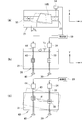
図6(a)に示されるように、コンベアモータ54により、ゴムベルト55を移動させることにより、実線で示す板状ワーク10Bを想像線の位置まで、x軸に沿ってXxだけ移動させることができる。このXxが、板状ワーク10Bを移動させるために必要なコンベア機構13の移動量に相当する。以下、Xxをコンベア機構の移動量と略記す。
図6(b)に示されるように、第1サーボモータ34と第2サーボモータ44により、第1ねじ軸33と第2ねじ軸43を同期して回すことにより、テーブル21を想像線の位置まで、y軸に沿ってYyだけ移動させることができる。このYyが、板状ワーク10Bを移動させるために必要なテーブル移動機構28の移動量に相当する。以下、Yyをテーブル移動機構の移動量と略記する。
図6(c)に示されるように、第1ねじ軸33を止めて、第2ねじ軸43だけを回す。すると、第1支軸35を中心にして、テーブル21が想像線の位置まで、角度αだけ回転(旋回)する。したがって、第1移動機構30と第2移動機構40とで、テーブル回転機構60が構成されたことになる。角度αが、板状ワーク10Bを回転させるために必要なテーブル回転機構60の移動量に相当する。以下、α(後述のθ)を、テーブル回転機構の移動量と略記する。
ただし、この発明では、テーブル移動機構28で、テーブル回転機構60を兼ねたので、テーブル回転機構60のために格別の機器を配置する必要はない。
反面、回転機構を用いないで、直線運動機構を利用して、テーブルを旋回させるため、テーブル移動機構28の作用が複雑化する。そのような構造のセンターリング装置20の作動原理を、幾何学的に説明する。
反面、回転機構を用いないで、直線運動機構を利用して、テーブルを旋回させるため、テーブル移動機構28の作用が複雑化する。そのような構造のセンターリング装置20の作動原理を、幾何学的に説明する。
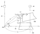
図7は、説明の都合で、第1ねじ軸33をy軸に重ね、第2ねじ軸43はその右に示される。そして、ゴムベルト55はx軸に重なっている。
図7に示されるように、x軸に目標センターリング位置にセンターリングされた板状ワーク10Cが、イメージされる。一方、第1象限に、センターリングされる前の板状ワーク10Bがあり、この板状ワーク10Bはカメラにより画像認識される。なお、板状ワーク10Bは、略台形状を呈し、非矩形板である。
図7に示されるように、x軸に目標センターリング位置にセンターリングされた板状ワーク10Cが、イメージされる。一方、第1象限に、センターリングされる前の板状ワーク10Bがあり、この板状ワーク10Bはカメラにより画像認識される。なお、板状ワーク10Bは、略台形状を呈し、非矩形板である。
目標センターリング位置における板状ワーク10Cの左上の頂点座標を(x0,y0)とする。板状ワーク10Cは、1枚ごとに形状、寸法がコンピュータで管理される。これらの情報は、コンピュータからずれ演算部(図5、符号58)へ予めインプットされる。すなわち、演算部は、予め頂点座標(x0,y0)を有している。
また、カメラで撮影された板状ワーク10Bにおける左上の頂点座標を(xs,ys)とする。この座標(xs,ys)は、カメラ画像を解析することにより、演算部(図5、符号58)で特定される。加えて、演算部は撮像から、板状ワーク10Cを基準にして、板状ワーク10Bがθだけ反時計廻りにずれていることを検出する。
座標(xs,ys)を、矢印(1)のように、座標(x1,y1)まで、x軸に沿って移動する。この移動は、図6(a)により実施する。
座標(x1,y1)を、矢印(2)のように、原点(0,0)を中心に角度θだけ時計廻りに回す。回転後の座標を(x2,y2)とする。この回転は、図6(c)により実施する。
座標(x2,y2)を、矢印(3)のように、座標(x0,y0)まで、y軸に沿って移動する。この移動は、図6(b)により実施する。
座標(x1,y1)を、矢印(2)のように、原点(0,0)を中心に角度θだけ時計廻りに回す。回転後の座標を(x2,y2)とする。この回転は、図6(c)により実施する。
座標(x2,y2)を、矢印(3)のように、座標(x0,y0)まで、y軸に沿って移動する。この移動は、図6(b)により実施する。
図7中、距離Lは、第1ねじ軸33と第2ねじ軸43の間隔であって、既知である。座標(x0,y0)、座標(xs,ys)及び角度θも既知である。
そこで、既知のθ、x0、y0、xs、ysで、コンベア機構の移動量、第1移動機構の移動量及び第2移動機構の移動量を確定することを、検討する。
そこで、既知のθ、x0、y0、xs、ysで、コンベア機構の移動量、第1移動機構の移動量及び第2移動機構の移動量を確定することを、検討する。

図7中、矢印(2)の区間では、第2ねじ軸43だけを回すことで、テーブルを旋回させる。
図8に示されるように、第2ねじ軸43は原点からLだけ離れている。第2移動機構により、テーブルをθだけ時計回りに旋回させることができ、そのときの第2移動機構の移動量は幾何学的に定まる。
図8に示されるように、第2ねじ軸43は原点からLだけ離れている。第2移動機構により、テーブルをθだけ時計回りに旋回させることができ、そのときの第2移動機構の移動量は幾何学的に定まる。

図9に示されるように、座標(x1,y1)と座標(x2,y2)は、半径R上の点であるため、次のような計算が行える。

図7中、矢印(3)の区間では、単純なy軸に沿った移動である。





以上により、次の表に示す演算式が定まる。

上記演算式に基づいて、図6に示す制御部59は、図6(a)にて、コンベアモータ54を制御して板状ワーク10Bを移動させ、図6(b)、(c)にて、第1サーボモータ34を制御して第1ねじ軸33を回し、第2サーボモータ44を制御して第2ねじ軸43を回す。結果、図7に示す板状ワーク10Bは、目標センターリング位置にある板状ワーク10Cに重なっている。
なお、コンベアモータ54と第1・第2サーボモータ34、44は、一括して同時に運転される。すなわち、同時に始動し、演算された移動量に達したものから順に停止させる。
図7に示す矢印(1)、矢印(2)、矢印(3)をこの順に実施するよりは、移動時間が大幅に短縮できる。ただし、同時に始動する他、順不同で始動させることは差し支えない。
図7に示す矢印(1)、矢印(2)、矢印(3)をこの順に実施するよりは、移動時間が大幅に短縮できる。ただし、同時に始動する他、順不同で始動させることは差し支えない。
上記演算式を検証する。
θ=5°、L=700(mm、以下同じ)、x0=350、y0=250、xs=500、ys=400とし、上式を計算した。
コンベアの移動量は、-183.6、
第1移動機構の移動量は、-120.9、
第2移動機構の移動量は、-186.5であり、図7と良好に合致した。
θ=5°、L=700(mm、以下同じ)、x0=350、y0=250、xs=500、ys=400とし、上式を計算した。
コンベアの移動量は、-183.6、
第1移動機構の移動量は、-120.9、
第2移動機構の移動量は、-186.5であり、図7と良好に合致した。
図1にて、第1センターリング装置20Aと第2センターリング装置20Bは各々カメラを備えているため、各々板状ワーク10B、10Bをセンターリングすることができる。
次に、長尺ワークのセンターリングについて説明する。
図10に示されるように、第1センターリング装置20Aと第2センターリング装置20Bに跨るように、長尺ワーク61Bが載っている。目標センターリング位置に置かれる長尺ワーク61Cは、想像線で示す。
図10に示されるように、第1センターリング装置20Aと第2センターリング装置20Bに跨るように、長尺ワーク61Bが載っている。目標センターリング位置に置かれる長尺ワーク61Cは、想像線で示す。
第2センターリング装置20Bのカメラによる撮像から座標(xs,ys)及びずれ角θが検出できる。また、予め座標(x0,y0)はインプットされている。
演算部での演算に基づいて制御部は、右のコンベアモータ54Aと左のコンベアモータ54Bを同期して運転する。
演算部での演算に基づいて制御部は、右のコンベアモータ54Aと左のコンベアモータ54Bを同期して運転する。
同時並行して、第1センターリング装置20Aの第1ねじ軸33Aは止めたままで、第1センターリング装置20Aの第1支軸35を全体の旋回中心とし、第1センターリング装置20Aの第2ねじ軸43Aと第2センターリング装置20Bの第1・第2ねじ軸33B、43Bを回す。第1センターリング装置20Aの第1支軸33Aを全体の旋回中心とし、両テーブルがθだけ旋回する。
y軸に沿った移動は、4つのサーボモータ34A、44A、34B、44Bを同期して回せばよい。
すなわち、制御部は、第1センターリング装置20Aの第1サーボモータ34Aと第2サーボモータ44A及び第2センターリング装置20Bの第1サーボモータ34Bと第2サーボモータ44Bを運転する。結果、板状ワーク61Bは、センターリングされ、板状ワーク61Cに重なる。
すなわち、制御部は、第1センターリング装置20Aの第1サーボモータ34Aと第2サーボモータ44A及び第2センターリング装置20Bの第1サーボモータ34Bと第2サーボモータ44Bを運転する。結果、板状ワーク61Bは、センターリングされ、板状ワーク61Cに重なる。
この例では、2基のセンターリング装置20A、20Bを直列に配置したが、3基以上を配置してもよい。そうすることで、ごく短い板状ワークから長大な長尺ワークまでのセンターリングが1つの設備で実施できる。
次に、本発明に係るセンターリング装置の変更例を説明する。
図11に示されるように、ベース26にレール62、62を敷き、これらのレール62、62にスライダー63をy軸に沿って移動可能に設け、移動用サーボモータ67で回されるねじ軸68で、スライダー63をy軸方向に移動させる。すなわち、この例では、テーブル移動機構28が、ねじ軸68と移動用サーボモータ67で構成される。したがって、テーブル移動機構28の構成は適宜変更可能である。
図11に示されるように、ベース26にレール62、62を敷き、これらのレール62、62にスライダー63をy軸に沿って移動可能に設け、移動用サーボモータ67で回されるねじ軸68で、スライダー63をy軸方向に移動させる。すなわち、この例では、テーブル移動機構28が、ねじ軸68と移動用サーボモータ67で構成される。したがって、テーブル移動機構28の構成は適宜変更可能である。
そして、スライダー63に回転用サーボモータ64を載せ、この回転用サーボモータ64に減速機65を載せ、この減速機65の減速機軸65aでテーブル21を支持させる。テーブル21に、4個の自在車輪66を設ける。自在車輪66がベース26上を走行することにより、テーブル21の上下動は抑制される。自在車輪66により、減速機軸65aへの曲げ荷重を大幅に下げることができる。
図12(a)に示されるように、減速機軸65aが原点(0,0)に置かれている。座標(x0,y0)、座標(xs,ys)及び角度θも既知である。
原点(0,0)を中心に、板状ワーク10Bを時計回りに、角度θだけ回す。回した後の頂点座標(x4,y4)は、図7での範囲(2)と同様に、幾何学的に定まる。
原点(0,0)を中心に、板状ワーク10Bを時計回りに、角度θだけ回す。回した後の頂点座標(x4,y4)は、図7での範囲(2)と同様に、幾何学的に定まる。
図12(b)に示されるように、板状ワーク10Bは方位が板状ワーク10Cと合致している。板状ワーク10Bをx軸に沿ってXxだけ移動させ、y軸に沿ってYyだけ移動させる。Xxは(x0-x4)、Yyは(y0-y4)で一義的に定まる。結果、板状ワーク10Bは板状ワーク10Cに重なる。
図11にて、コンベア機構23でXxの移動を行い、回転用サーボモータ64でずれ角θを是正し、移動用サーボモータ65とねじ軸66とでYyの移動を行えばよい。
すなわち、この例では、移動用サーボモータ65とねじ軸66が、テーブル移動機構28に該当し、回転用サーボモータ64と減速機65が、テーブル回転機構60に該当する。
すなわち、この例では、移動用サーボモータ65とねじ軸66が、テーブル移動機構28に該当し、回転用サーボモータ64と減速機65が、テーブル回転機構60に該当する。
なお、減速機65は、遊星ギヤ減速機など高減速比が得られものを採用する。ただし、このように精密な回転角度が要求されるので、高減速比の減速機が必要である。
一方、図4に示すねじ軸43は、これ自体が高減速比減速機を兼ねる。よって、図4の構成の方が、コスタダウンを容易に図ることができる。
一方、図4に示すねじ軸43は、これ自体が高減速比減速機を兼ねる。よって、図4の構成の方が、コスタダウンを容易に図ることができる。
また、図1で説明したように、本発明のセンターリング装置は成形プレス機の入口に配置されることが望ましいが、その他の用途に使用することは差し支えない。
また、図1に示されるように、板状ワークは2つのテーブルに跨る長さの長尺材である場合、本発明のセンターリング装置20により、長尺材の回転と移動とを同時に行うことで長尺材のセンターリングを実施する。回転と移動をシリーズに(順に)行う場合に比較して、本発明では回転と移動を同時に並行して行うため、長尺材のセンターリング作業時間を削減し、生産性が高まる。
また、図2に示されるように、2つのテーブルの各々に板状ワークを載せた場合、本発明のセンターリング装置20により、2枚の板状ワークの回転と移動とを同時に行うことで板状ワークのセンターリングを互いに独立して実施する。回転と移動を同時に並行して行うため、2枚の板状ワークのセンターリング作業時間を削減し、生産性が高まる。また、2枚の板状ワークを同時にセンターリングするため、生産性がより向上する。
また、図3に示されるように、台形など異形材のセンターリングが実施できる。異形材は矩形材と変わることなく、迅速に且つ容易にセンターリングすることができる。
尚、実施例では、直列に2つのテーブルを並べたが、3つ以上のテーブルを直列に並べることは差し支えない。
本発明は、本発明のセンターリング装置は成形プレス機の入口に配置されることが望ましい。
10…板状ワーク、10B…センターリング前の板状ワーク、10C…目標センターリング位置にセンターリングされた板状ワーク、12…第1ロボット、15…第2ロボット、20…センターリング装置、21…テーブル、23…コンベア機構、28…テーブル移動機構、30…第1移動機構、40…第2移動機構、56…カメラ、58…演算部、59…制御部、60…テーブル回転機構。
Claims (8)
- 板状ワークを水平方向に搬送するコンベア機構を有するテーブルと、
このテーブル上に置かれている前記板状ワークを撮影するカメラと、
前記搬送方向と直交する方向に前記テーブルを水平に移動させるテーブル移動機構と、
前記テーブルを鉛直軸廻りに回すテーブル回転機構と、
前記目標センターリング位置情報と前記カメラで取得した位置情報とを比較して、前記コンベア機構の移動量、前記テーブル移動機構の移動量及び前記テーブル回転機構の移動量を演算する演算部と、
この演算部で求めた移動量に基づいて、前記コンベア機構、前記テーブル移動機構及び前記テーブル回転機構を制御する制御部と、からなることを特徴とする板状ワークのセンターリング装置。 - 前記テーブル移動機構は、互いに平行に配置される第1移動機構と第2移動機構とからなる請求項1記載の板状ワーク用センターリング装置。
- 前記演算部は、前記カメラで取得した位置情報から、前記板状ワークの特徴点を捉え、前記コンベア機構の移動量、前記テーブル移動機構の移動量及び前記テーブル回転機構の移動量を演算する請求項1記載の板状ワークのセンターリング装置。
- 請求項3記載の板状ワーク用センターリング装置が、直列に複数基設けられている板状ワークのセンターリング装置。
- 前記板状ワークは複数のテーブルに跨る長さの長尺材である請求項4記載の板状ワークのセンターリング装置。
- 前記テーブルの各々に前記板状ワークが載っている請求項4記載の板状ワークのセンターリング装置。
- 前記板状ワークは、異形材である請求項5記載の板状ワークのセンターリング装置。
- 板状ワークを水平方向に搬送するコンベア機構を有するテーブルと、
このテーブル上に置かれている前記板状ワークを撮影するカメラと、
前記搬送方向と直交する方向に前記テーブルを水平に移動させるテーブル移動機構と、
前記テーブルを鉛直軸廻りに回すテーブル回転機構と、
前記目標センターリング位置情報と前記カメラで取得した位置情報とを比較して、前記コンベア機構の移動量、前記テーブル移動機構の移動量及び前記テーブル回転機構の移動量を演算する演算部と、
この演算部で求めた移動量に基づいて、前記コンベア機構、前記テーブル移動機構及び前記テーブル回転機構を制御する制御部と、からなる板状ワークのセンターリング装置であって、
前工程から搬送された板状ワークを次工程へ移載する第1ロボットと、移動制御された前記板状ワークを次工程へ移載する第2ロボットを備え、
前記テーブル移動機構は、互いに平行に配置される第1移動機構と第2移動機構とからなり、
前記演算部は、前記カメラで取得した位置情報から、前記板状ワークの特徴点を捉え、前記コンベア機構の移動量、前記テーブル移動機構の移動量及び前記テーブル回転機構の移動量を演算するものである、板状ワークのセンターリング装置。
Priority Applications (2)
| Application Number | Priority Date | Filing Date | Title |
|---|---|---|---|
| US14/437,952 US9433994B2 (en) | 2012-10-24 | 2013-08-12 | Centering device for plate-shaped workpiece |
| CN201380049588.3A CN104768674B (zh) | 2012-10-24 | 2013-08-12 | 板状工件的定心装置 |
Applications Claiming Priority (2)
| Application Number | Priority Date | Filing Date | Title |
|---|---|---|---|
| JP2012-235062 | 2012-10-24 | ||
| JP2012235062A JP5604496B2 (ja) | 2012-10-24 | 2012-10-24 | 板状ワーク用センターリング装置 |
Publications (1)
| Publication Number | Publication Date |
|---|---|
| WO2014064989A1 true WO2014064989A1 (ja) | 2014-05-01 |
Family
ID=50544370
Family Applications (1)
| Application Number | Title | Priority Date | Filing Date |
|---|---|---|---|
| PCT/JP2013/071780 Ceased WO2014064989A1 (ja) | 2012-10-24 | 2013-08-12 | 板状ワークのセンターリング装置 |
Country Status (4)
| Country | Link |
|---|---|
| US (1) | US9433994B2 (ja) |
| JP (1) | JP5604496B2 (ja) |
| CN (1) | CN104768674B (ja) |
| WO (1) | WO2014064989A1 (ja) |
Cited By (1)
| Publication number | Priority date | Publication date | Assignee | Title |
|---|---|---|---|---|
| CN107066433A (zh) * | 2015-11-25 | 2017-08-18 | 柯尼卡美能达美国研究所有限公司 | 偏移图像中的旋转的表格 |
Families Citing this family (11)
| Publication number | Priority date | Publication date | Assignee | Title |
|---|---|---|---|---|
| US9409716B2 (en) * | 2014-06-13 | 2016-08-09 | Bastian Solutions, Llc | Cross belt slat sorter |
| NL2017923B1 (en) * | 2016-12-05 | 2018-06-18 | Qimarox Patenten B V | Device and method configured to control rotation of an object on a carrier |
| JP6710171B2 (ja) * | 2017-02-24 | 2020-06-17 | 株式会社栗本鐵工所 | 位置決め装置、繊維強化樹脂成形体の製造装置及び成形型投入方法 |
| DE102017111800A1 (de) * | 2017-05-30 | 2018-12-06 | Wisco Lasertechnik Gmbh | Verfahren zur Ausrichtung zweier Werkstücke zur Ausbildung einer Fügeverbindung und Manipulator |
| CN107088590A (zh) * | 2017-06-07 | 2017-08-25 | 嘉兴宝程自动化设备有限公司 | 一种快速识别板材偏移的冲床送料机及其工作方法 |
| JP6893357B2 (ja) * | 2017-08-28 | 2021-06-23 | 株式会社小矢部精機 | 位置決め装置 |
| CN107695191B (zh) * | 2017-10-11 | 2019-01-18 | 湖南大学 | 一种多工位级进模具的尾料送料装置及其工作方法 |
| WO2019082112A1 (en) * | 2017-10-27 | 2019-05-02 | Ronchi Mario S.P.A. | APPARATUS FOR ALIGNING RANDOMIZED CONTAINERS COMPRISING INDEPENDENT EXTRACTION MEANS EACH OF OTHERS |
| CN112588593A (zh) * | 2020-12-10 | 2021-04-02 | 安徽卡孚光电子科技有限公司 | 一种电子产品加工用外观检查装置及方法 |
| CN114082862A (zh) * | 2021-11-17 | 2022-02-25 | 哈工大机器人南昌智能制造研究院 | 一种滚压成型设备全自动下料码垛装置 |
| CN119175299B (zh) * | 2024-11-12 | 2025-03-21 | 太仓市富远精密模具有限公司 | 一种料带式端子自动送料连续冲压设备 |
Citations (2)
| Publication number | Priority date | Publication date | Assignee | Title |
|---|---|---|---|---|
| JP2000229726A (ja) * | 1999-02-12 | 2000-08-22 | Homei Sangyo Kk | 物品搬送装置 |
| JP2008094547A (ja) * | 2006-10-11 | 2008-04-24 | Hitachi Zosen Fukui Corp | シートの搬送方法及びその装置 |
Family Cites Families (18)
| Publication number | Priority date | Publication date | Assignee | Title |
|---|---|---|---|---|
| US5363968A (en) * | 1991-08-23 | 1994-11-15 | Pfizer Inc. | Automatic blister inspection system |
| DE4221994C2 (de) * | 1992-07-04 | 1995-07-20 | Agfa Gevaert Ag | Einrichtung zum Behandeln von fotografischen Schichtträgern |
| US5238099A (en) * | 1992-08-04 | 1993-08-24 | Premark Feg Corporation | Conveying system |
| US5370216A (en) * | 1993-03-05 | 1994-12-06 | Shibuya Kogyo Co., Ltd. | Apparatus for aligning vessels |
| JP2972489B2 (ja) | 1993-06-15 | 1999-11-08 | 株式会社日本製鋼所 | 薄板材料の位置決め装置 |
| JP3335517B2 (ja) * | 1995-12-25 | 2002-10-21 | ワイケイケイ株式会社 | 物品整送装置 |
| JP3894461B2 (ja) * | 1997-01-17 | 2007-03-22 | キヤノンアネルバ株式会社 | 非接触式磁気搬送装置の位置決め制御装置および位置決め制御方法 |
| US6256091B1 (en) * | 1997-08-25 | 2001-07-03 | Nippon Maxis Co., Ltd. | Transparent substrate mounting platform, transparent substrate scratch inspection device, transparent substrate bevelling inspection method and device, and transparent substrate inspection method |
| JP3496212B2 (ja) * | 1998-03-06 | 2004-02-09 | 三菱マテリアル株式会社 | 打ち抜き方法およびこの方法に用いる打ち抜き装置 |
| US7353954B1 (en) * | 1998-07-08 | 2008-04-08 | Charles A. Lemaire | Tray flipper and method for parts inspection |
| AU742980B2 (en) * | 1999-10-13 | 2002-01-17 | Kawasaki Jukogyo Kabushiki Kaisha | Random work arranging device |
| GB9926555D0 (en) * | 1999-11-09 | 2000-01-12 | Ishida Europ Mfg Ltd | Method and apparatus for orienting flexible walled articles |
| DE102007036020A1 (de) * | 2007-08-01 | 2009-02-05 | Weber Maschinenbau Gmbh Breidenbach | Ausrichten von Lebensmittelprodukten |
| JP2009054933A (ja) * | 2007-08-29 | 2009-03-12 | Ryusyo Industrial Co Ltd | ウエハ搬送システム |
| ITUD20070197A1 (it) * | 2007-10-24 | 2009-04-25 | Baccini S P A | Dispositivo e procedimento di allineamento per allineare piastre per circuiti elettronici |
| ATE496711T1 (de) * | 2008-03-12 | 2011-02-15 | Schuler Automation Gmbh & Co | Vorrichtung und verfahren zur lageausrichtung von plattenförmigen teilen |
| JP5769479B2 (ja) * | 2011-04-13 | 2015-08-26 | 日本発條株式会社 | ワーク供給装置及びその表裏整合分離装置 |
| JP5472214B2 (ja) * | 2011-06-20 | 2014-04-16 | 株式会社安川電機 | ピッキングシステム |
-
2012
- 2012-10-24 JP JP2012235062A patent/JP5604496B2/ja active Active
-
2013
- 2013-08-12 WO PCT/JP2013/071780 patent/WO2014064989A1/ja not_active Ceased
- 2013-08-12 US US14/437,952 patent/US9433994B2/en active Active
- 2013-08-12 CN CN201380049588.3A patent/CN104768674B/zh active Active
Patent Citations (2)
| Publication number | Priority date | Publication date | Assignee | Title |
|---|---|---|---|---|
| JP2000229726A (ja) * | 1999-02-12 | 2000-08-22 | Homei Sangyo Kk | 物品搬送装置 |
| JP2008094547A (ja) * | 2006-10-11 | 2008-04-24 | Hitachi Zosen Fukui Corp | シートの搬送方法及びその装置 |
Cited By (2)
| Publication number | Priority date | Publication date | Assignee | Title |
|---|---|---|---|---|
| CN107066433A (zh) * | 2015-11-25 | 2017-08-18 | 柯尼卡美能达美国研究所有限公司 | 偏移图像中的旋转的表格 |
| CN107066433B (zh) * | 2015-11-25 | 2020-05-08 | 柯尼卡美能达美国研究所有限公司 | 偏移图像中的旋转的表格 |
Also Published As
| Publication number | Publication date |
|---|---|
| CN104768674A (zh) | 2015-07-08 |
| US9433994B2 (en) | 2016-09-06 |
| JP2014083569A (ja) | 2014-05-12 |
| JP5604496B2 (ja) | 2014-10-08 |
| CN104768674B (zh) | 2017-03-15 |
| US20150314360A1 (en) | 2015-11-05 |
Similar Documents
| Publication | Publication Date | Title |
|---|---|---|
| WO2014064989A1 (ja) | 板状ワークのセンターリング装置 | |
| RU2671239C1 (ru) | Способ вырезания листового стекла и позиционирования вырезанного листового стекла и устройство для его осуществления | |
| KR101465283B1 (ko) | 중앙정치장치 | |
| CN204294787U (zh) | 滚动折边头、用于利用串列滚子组进行滚动折边的设备 | |
| CN101239366A (zh) | 折边加工方法及折边加工装置 | |
| US20170165738A1 (en) | Workpiece conveying apparatus for a pressing machine | |
| US10793464B2 (en) | Glass plate bend-breaking method and bend breaking apparatus thereof | |
| KR102126560B1 (ko) | 복합 레일 교정 장치 | |
| KR102480548B1 (ko) | 표면 처리를 위한 장치 | |
| KR100668068B1 (ko) | 다양한 형상의 이중 곡률을 가지는 금속판재를 성형하기위한 선형 배열 롤셋 및 이를 이용한 성형방법 | |
| KR20150132729A (ko) | 연성 소재 펀칭머신용 소재 클램핑장치 | |
| JP5280690B2 (ja) | 方向転換装置および搬送装置 | |
| US8327678B1 (en) | Roll-forming machine with a feed gap adjustment structure | |
| JPS59163038A (ja) | トランスフアプレスにおけるワ−ク搬送用フインガ−の位置調整装置 | |
| JP2023093309A (ja) | 折割治具及び折割加工方法 | |
| JP2011200910A (ja) | ロールベンダ及びロール曲げ加工方法 | |
| JP2019529120A5 (ja) | ||
| KR20160042401A (ko) | 반송 장치 및 진공 장치 | |
| CN112207151A (zh) | 一种板材平面度整形机及其整形工艺 | |
| KR101432092B1 (ko) | 롤러 타입 패널 절곡 장치 | |
| JPH06247728A (ja) | 板状材の曲げ成形装置のアライメント方法及びその装置 | |
| JP2019038023A5 (ja) | ||
| TWI829244B (zh) | 用於捲對捲製程之工作桌 | |
| CN213495729U (zh) | 一种板材平面度整形机 | |
| CN215970054U (zh) | 一种加压机构 |
Legal Events
| Date | Code | Title | Description |
|---|---|---|---|
| 121 | Ep: the epo has been informed by wipo that ep was designated in this application |
Ref document number: 13848824 Country of ref document: EP Kind code of ref document: A1 |
|
| WWE | Wipo information: entry into national phase |
Ref document number: 14437952 Country of ref document: US |
|
| NENP | Non-entry into the national phase |
Ref country code: DE |
|
| 122 | Ep: pct application non-entry in european phase |
Ref document number: 13848824 Country of ref document: EP Kind code of ref document: A1 |