WO2014064902A1 - ミラーユニットおよび撮像装置 - Google Patents
ミラーユニットおよび撮像装置 Download PDFInfo
- Publication number
- WO2014064902A1 WO2014064902A1 PCT/JP2013/006111 JP2013006111W WO2014064902A1 WO 2014064902 A1 WO2014064902 A1 WO 2014064902A1 JP 2013006111 W JP2013006111 W JP 2013006111W WO 2014064902 A1 WO2014064902 A1 WO 2014064902A1
- Authority
- WO
- WIPO (PCT)
- Prior art keywords
- mirror member
- mirror
- motor
- rotating body
- main mirror
- Prior art date
Links
Images


Classifications
-
- G—PHYSICS
- G03—PHOTOGRAPHY; CINEMATOGRAPHY; ANALOGOUS TECHNIQUES USING WAVES OTHER THAN OPTICAL WAVES; ELECTROGRAPHY; HOLOGRAPHY
- G03B—APPARATUS OR ARRANGEMENTS FOR TAKING PHOTOGRAPHS OR FOR PROJECTING OR VIEWING THEM; APPARATUS OR ARRANGEMENTS EMPLOYING ANALOGOUS TECHNIQUES USING WAVES OTHER THAN OPTICAL WAVES; ACCESSORIES THEREFOR
- G03B19/00—Cameras
- G03B19/02—Still-picture cameras
- G03B19/12—Reflex cameras with single objective and a movable reflector or a partly-transmitting mirror
-
- G—PHYSICS
- G03—PHOTOGRAPHY; CINEMATOGRAPHY; ANALOGOUS TECHNIQUES USING WAVES OTHER THAN OPTICAL WAVES; ELECTROGRAPHY; HOLOGRAPHY
- G03B—APPARATUS OR ARRANGEMENTS FOR TAKING PHOTOGRAPHS OR FOR PROJECTING OR VIEWING THEM; APPARATUS OR ARRANGEMENTS EMPLOYING ANALOGOUS TECHNIQUES USING WAVES OTHER THAN OPTICAL WAVES; ACCESSORIES THEREFOR
- G03B2205/00—Adjustment of optical system relative to image or object surface other than for focusing
Definitions
- the present invention relates to a mirror unit and an imaging device.
- the mirror unit includes a mirror member that rotates about the rotation axis, a motor, a drive lever that is driven by the motor, and a bias that biases the mirror member toward the drive lever.
- a control unit that controls a drive current for driving the motor, and the control unit reduces the drive current after driving the motor by supplying the drive current to the motor, and the biasing spring is an inertia of the motor Charged by force.
- the mirror unit includes a mirror member that rotates about a rotation axis, a motor, a drive lever that is driven by the motor, and a bias that biases the mirror member toward the drive lever.
- a control unit that controls a drive current for driving the motor, and the control unit moves the mirror member in the second direction from the state in which the mirror member is biased in the first direction; When the drive lever is driven, the drive current is decreased.
- an imaging apparatus includes the mirror unit and an imaging unit that captures an image of the subject using light from the subject that has passed through the mirror unit.
- the schematic cross section of the camera 100 in one Embodiment is shown.
- a schematic cross section of the camera 100 is shown.
- a side perspective view of a part of the mirror unit 400 is shown.
- a side perspective view of a part of the mirror unit 400 is shown.
- Side surface perspective drawing in the timing after the timing shown in FIG. 4 is shown.
- Side surface perspective drawing in the timing after the timing shown in FIG. 5 is shown.
- Side surface perspective drawing in the timing after the timing shown in FIG. 6 is shown.
- the side perspective view in the timing after the timing shown in FIG. 7 is shown.
- the side perspective view in case the main mirror member 410 exists in a retracted position is shown.
- An example of the time evolution of the angle of the main mirror member 410 and the duty ratio of the drive current is schematically shown.
- a side perspective view of a part of the mirror unit 400 is shown. Side surface perspective drawing in the timing after the timing shown in FIG. 11 is shown. Side surface perspective drawing in the timing after the timing shown in FIG. 12 is shown. Side surface perspective drawing in the timing after the timing shown in FIG. 13 is shown. Side surface perspective drawing in the timing after the timing shown in FIG. 14 is shown. Side surface perspective drawing in the timing after the timing shown in FIG. 15 is shown.
- An example of the time evolution of the angle of the main mirror member 410 and the duty ratio of the drive current is schematically shown.
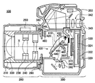
- FIG. 1 shows a schematic cross section of a camera 100 according to an embodiment.
- the camera 100 is a single-lens reflex camera as an example of an imaging device.
- the camera 100 includes a lens unit 200 and a camera body 300.
- the lens unit 200 includes a fixed cylinder 210, a lens group 220, a lens group 230, a lens group 240, a lens side control unit 250, and a camera mount 260.
- the lens unit 200 is detachably attached to the camera body 300.
- the camera mount 260 is coupled to the lens mount 360 included in the camera body 300, the lens unit 200 is attached to the camera body 300.
- the lens group 220, the lens group 230, and the lens group 240 are arranged along the optical axis X inside the fixed cylinder 210 to form an optical system. At least a part of the lens group 220, the lens group 230, and the lens group 240 can be moved along the optical axis X. As the lens group 220, the lens group 230, and the lens group 240 move along the optical axis X, the magnification and focus position of the optical system change.
- the lens side control unit 250 controls the lens unit 200 itself.
- the lens side control unit 250 communicates with the body side control unit 322 of the camera body 300.
- the lens unit 200 attached to the camera body 300 operates in cooperation with the camera body 300.
- the lens-side control unit 250 moves at least a part of the lens group 220, the lens group 230, and the lens group 240 along the optical axis X in accordance with control from the body-side control unit 322 based on instructions for focus adjustment and field angle adjustment. To move.
- the mirror unit 400 is provided at a position along the optical axis X with respect to the lens unit 200.
- the mirror unit 400 includes a main mirror member 410, a sub mirror member 450, a stop member 440, and a buffer member 480.
- the main mirror member 410 includes a main mirror 420.
- the main mirror member 410 rotates around the main mirror rotation shaft 430. Specifically, the main mirror member 410 rotates around the main mirror rotation shaft 430 while holding the main mirror 420.
- the main mirror rotation axis 430 is located at a position off the optical axis X.
- the sub mirror member 450 includes a sub mirror 460.
- the sub mirror member 450 rotates about the sub mirror rotation axis 470. Specifically, the sub mirror member 450 rotates around the sub mirror rotation shaft 470 in the main mirror member 410 while holding the sub mirror 460.
- the main mirror member 410 includes a drive pin 490 protruding in a direction along the main mirror rotation axis 430.
- the drive pin 490 is displaced in a plane perpendicular to the main mirror rotation shaft 430, the main mirror member 410 rotates around the main mirror rotation shaft 430.
- the stop member 440 contacts the main mirror member 410 and stops the rotation of the main mirror member 410.
- the sub mirror member 450 is supported by the main mirror member 410 and moves relative to the main mirror member 410 according to the rotation of the main mirror member 410. Specifically, the sub mirror member 450 is displaced with respect to the main mirror member 410 by a link mechanism that operates as the main mirror member 410 rotates. That is, the sub mirror member 450 moves relative to the main mirror member 410 as the main mirror member 410 rotates while moving together with the main mirror member 410.
- FIG. 1 shows a state in which the front end of the main mirror member 410 is in contact with the stop member 440.
- the main mirror 420 is at a position crossing the optical axis X, and is in a state of being advanced into the subject light flux.
- the main mirror member 410 is positioned at a position where the front end of the main mirror member 410 is in contact with the stop member 440.
- the fact that the front end of the main mirror member 410 is in the position where it comes into contact with the stop member 440 may be referred to as the main mirror member 410 being in the advanced position.
- the main mirror 420 has a half mirror region formed in a part of the main mirror 420.
- a part of the subject light flux passes through the half mirror area of the main mirror 420 and enters the sub mirror 460.
- Part of the subject luminous flux incident on the sub mirror 460 is reflected toward the focusing optical system 390 and enters the focus detection sensor 392.
- the focus detection sensor 392 receives the subject luminous flux and outputs a signal indicating the amount of received light to the body side control unit 322.
- the body side control unit 322 performs focusing control based on the signal output from the photometric sensor 350.
- the body side control unit 322 is configured to reduce the defocus amount based on the defocus amount of the optical system of the lens unit 200 calculated based on the signal output from the focus detection sensor 392.
- At least a part of the lens group 220, the lens group 230, and the lens group 240 is moved to 250. With such focusing control, the subject light is focused on the position of the imaging surface of the imaging device 370 by the optical system of the lens unit 200.
- the main mirror member 410 When the main mirror member 410 is in the advanced position, the main mirror 420 reflects a part of the subject light flux and guides it to the focusing screen 346.
- the focusing screen 346 is at a position optically conjugate with the imaging surface of the imaging element 370.
- the subject light beam guided to the focusing screen 346 is emitted from the finder 340 exposed on the back surface of the camera body 300 through the pentaprism 344 and the finder optical system 342. Accordingly, the subject image on the focusing screen 346 is presented to the user from the viewfinder 340 as an erect image.
- Part of the subject luminous flux emitted from the pentaprism 344 is received by the photometric sensor 350 of the finder optical system 342.
- the photometric sensor 350 receives the subject luminous flux and outputs a signal corresponding to the amount of received light.
- the body side control unit 322 performs exposure control based on the signal output from the photometric sensor 350. For example, the body-side control unit 322 calculates the brightness of the subject based on a signal from the photometric sensor 350, and determines exposure conditions such as an aperture value, a shutter speed, and ISO sensitivity according to the calculated brightness. . Thereby, the camera 100 captures an image of the subject under an appropriate exposure condition according to the brightness of the subject.
- a focal plane shutter 380 In the camera body 300, a focal plane shutter 380, an optical filter 372, and an image sensor 370 are provided along the optical axis X.
- the focal plane shutter 380 opens and closes, and opens or closes the image sensor 370 with respect to the incident subject light flux.
- the optical filter 372 removes infrared rays and ultraviolet rays from the subject light flux incident on the image sensor 370.
- the optical filter 372 also functions as a protective member that protects the surface of the image sensor 370.
- the optical filter 372 functions as a low-pass filter.
- the optical filter 372 reduces the spatial frequency component in the spatial frequency region that exceeds the Nyquist frequency of the image sensor 370 in the incident subject light flux. Thereby, moire in an image of a subject obtained by imaging with the imaging element 370 is suppressed.
- the image sensor 370 converts the subject light flux into an electrical signal and outputs it.
- a solid-state imaging device such as a CCD sensor or a CMOS sensor can be exemplified.
- the imaging element 370 is an example of an imaging unit that captures an image of a subject using light from the subject that has passed through the mirror unit 400.
- a rear display unit 330 is provided on the rear housing of the camera body 300.
- the rear display unit 330 is formed by a liquid crystal display device or the like.
- a substrate 320 is provided between the image sensor 370 and the rear display unit 330.
- Electronic circuits such as a body side control unit 322 and an image processing unit 324 are mounted on the substrate 320.
- the image processing unit 324 generates subject image data based on the electronic signal output from the image sensor 370.
- the image data generated by the image processing unit 324 is recorded as an image file or the like on a nonvolatile recording medium such as a flash memory.
- the image processing unit 324 also performs processing for generating image data of an image displayed on the rear display unit 330.
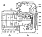
- FIG. 2 shows a schematic cross section of the camera 100.
- FIG. 2 shows a state in which the front end of the main mirror member 410 is in the vicinity of the buffer member 480 in the camera body 300. In this state, the main mirror 420 is at a position that does not cross the optical axis X, and is in a state of being retracted from the subject light flux. Such a state in which the main mirror member 410 is retracted from the subject light beam may be referred to as the main mirror member 410 being in the retracted position.
- the retreat position is an example of a first rotation position
- the advance position is an example of a second rotation position.
- the main mirror member 410 rotates around the main mirror rotation shaft 430 and moves toward the retracted position.
- the main mirror member 410 stops after the front end contacts the buffer member 480.
- the sub mirror member 450 rotates together with the main mirror member 410 and rotates around the sub mirror rotation shaft 470 so as to be in contact with the main mirror member 410. Become. As a result, the main mirror 420 and the sub mirror 460 are retracted from the optical path of the subject light flux. In this state, the subject luminous flux incident on the mirror unit 400 passes through the mirror unit 400 and travels toward the image sensor 370.
- the focal plane shutter 380 In response to the main mirror member 410 moving to the retracted position, the focal plane shutter 380 is opened. As a result, the subject luminous flux incident from the lens unit 200 passes through the optical filter 372 and is received by the image sensor 370. When the main mirror member 410 is in the retracted position and the focal plane shutter 380 is in an open state, the imaging element 370 can be imaged with the subject light flux.
- the focal plane shutter 380 is closed, and the main mirror member 410 returns to the advanced position shown in FIG. Image data obtained by imaging with the imaging element 370 is recorded on a recording medium.
- the main mirror member 410 repeats the operation in which the front end of the main mirror member 410 reciprocates between the stop member 440 and the buffer member 480 every time a photographing operation is performed.
- the main mirror 420 guides the light flux to the finder 340, the focus detection sensor 392, and the photometric sensor 350. Therefore, the movement of the main mirror member 410 causes the subject image presented from the finder 340 to be blurred.
- the movement of the main mirror member 410 affects the focus control and exposure control. For example, when the main mirror member 410 is moved from the retracted position to the advanced position, if the tip of the main mirror member 410 collides strongly with the stop member 440 and greatly bounces, it takes time until the bounce converges. End up. Therefore, the subject image presented from the finder 340 is blurred for a long time. In addition, in order to accurately perform focusing control and exposure control, it is necessary to wait for the bounce of the main mirror member 410 to converge.
- the main mirror member 410 when the main mirror member 410 is moved to the advanced position, not only the tip of the main mirror member 410 is quickly moved to the advanced position, but also the movement of the main mirror member 410 is quickly stopped by the stop member 440. It is necessary to stop in a state where it is accurately positioned at the specified advance position. Thus, even when the main mirror member 410 is changed from the retracted position to the advanced position, it is desirable to operate the main mirror member 410 stably.
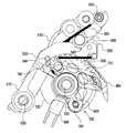
- FIG. 3 shows a side perspective view of a part of the mirror unit 400.
- FIG. 3 is a side perspective view of the mirror unit 400 viewed from the direction along the main mirror rotation axis 430 when the main mirror member 410 is in the advanced position.
- the mirror unit 400 includes an urging spring 500, a driving lever 510, a rotating unit 700, a connecting member 600, and a position sensor 800 as a part of a driving mechanism that drives the main mirror member 410.
- the rotation unit 700 is rotated by a motor.
- the rotation of the motor is controlled by the body side control unit 322.
- the body side control unit 322 controls the drive current that drives the motor.
- the rotating unit 700 includes a gear 790, a cam 710, and a position detecting member 720 that rotate integrally with the rotating shaft 730 as a rotating shaft.
- the rotation shaft 730 is substantially parallel to the main mirror rotation shaft 430.
- Rotating unit 700 rotates when the rotational force of the motor is transmitted to gear 790.
- the rotational force of the motor is transmitted from the motor output shaft to the gear 790 via one or more gears.
- the body side control unit 322 controls driving of the motor.
- the body side control unit 322 controls the driving of the motor by controlling the current supplied to the motor.
- the connecting member 600 connects the rotation unit 700 and the drive lever 510 to transmit the power of the rotation unit 700 to the drive lever 510.
- the connecting member 600 is connected to the rotating unit 700 at a position away from the main mirror rotating shaft 430 of the rotating unit 700.
- one end of the connecting member 600 is connected to the rotating unit 700 at a connecting portion 740 provided at a position away from the rotating shaft 730.
- the other end of the connecting member 600 is connected to the drive lever 510 at the connecting portion 520 of the drive lever 510.
- the drive lever 510 rotates around the rotation shaft 530 at one end of the drive lever.
- the rotation shaft 530 is substantially parallel to the main mirror rotation shaft 430.
- Both ends of the connecting member 600 are not fixed to the connecting portion 740 and the connecting portion 520, and are connected with a degree of freedom. Accordingly, the rotational force of the rotation unit 700 is transmitted to the drive lever 510 via the connecting member 600, and the drive lever 510 rotates around the rotation shaft 530 in conjunction with the rotation movement of the rotation unit 700. Thus, the drive lever 510 is driven by the motor.
- the drive lever 510 has a cam follower 540.
- the cam follower 540 comes into contact with the cam 710 according to the rotation state of the rotation unit 700.
- the cam follower 540 is not in contact with the cam 710.
- the cam follower 540 contacts the cam 710 and the drive lever 510 is supported.
- the drive lever 510 has a contact lever 550.
- the contact lever 550 rotates around a rotation shaft formed integrally with the drive lever 510.
- the rotation range of the contact lever 550 is restricted at a position where a part of the contact lever 550 protrudes from the drive lever 510.
- biasing spring 500 One end of a biasing spring 500 is fixed to the contact lever 550.
- the other end of the biasing spring 500 is in contact with the drive pin 490 depending on the position of the main mirror member 410.
- the biasing spring 500 exerts a biasing force on the drive pin 490.
- the biasing spring 500 sandwiches the main mirror member 410 and the drive lever 510.
- the biasing spring 500 is an example of a biasing spring that biases the main mirror member 410 toward the drive lever 510.
- the biasing spring 500 does not exert a biasing force on the contact lever 550.
- the drive lever 510 has a recess 560.
- the recess 560 contacts the drive pin 490 according to the position of the main mirror member 410.
- the recess 560 is not in contact with the drive pin 490.
- the drive pin 490 moves while changing the contact position in the recess 560 during a part of the period in which the main mirror member 410 moves from the advanced position to the retracted position.
- the main mirror member 410 When the main mirror member 410 is in the advanced position, the main mirror member 410 is in contact with the stop member 440.
- the biasing spring 500 biases the drive pin 490, the main mirror member 410 is biased in a direction to be pressed against the stop member 440.
- the connecting portion 740 When the main mirror member 410 is in the advanced position, the connecting portion 740 is located on the left side of the straight extension line connecting the connecting portion 520 and the rotating shaft 730.
- the connecting portion 740 is in a state where the connecting portion 740, the connecting portion 520, and the rotating shaft 730 are rotated by a predetermined angle in the clockwise direction in the drawing from a state where they are aligned. Therefore, the rotation unit 700 is restricted from rotating counterclockwise in the drawing by the restoring force of the biasing spring 500. Therefore, the restoring force of the biasing spring 500 acts in a direction in which the main mirror member 410 is pressed against the stop member 440. As a result, the main mirror member 410 is positioned in contact with the stop member 440.
- the position sensor 800 detects the rotation position of the rotation unit 700.
- the position sensor 800 detects the rotational position of the rotation unit 700 by detecting the position of the position detection member 720.
- the position sensor 800 is a photo interrupter as an example.
- the position detecting member 720 has a light shielding property.
- the position sensor 800 detects the position of the position detection member 720 by detecting the light shielding state by the position detection member 720.
- the body-side control unit 322 supplies a drive current to the motor when the main mirror member 410 is to be moved to the retracted position.
- the body-side control unit 322 supplies a drive current to the motor in a direction in which the rotation unit 700 rotates counterclockwise in the drawing.
- the body-side control unit 322 starts supplying the drive current with an initial value of a predetermined duty ratio that is greater than zero.
- the body-side control unit 322 increases the duty ratio of the drive current with time from the initial value. Specifically, the body side control unit 322 monotonically increases the duty ratio of the drive current with respect to time from the initial value. Therefore, the time average value of the drive current increases with time.
- an increase in drive current means that the magnitude of the drive current increases.
- the decrease in the drive current means that the magnitude of the drive current is decreased.
- the drive current supplied to the motor may have different current directions when moved from the advanced position to the retracted position and when moved from the advanced position to the retracted position.
- the change over time in the magnitude of the drive current in each case will be explained.
- the drive current is duty-driven, but the increase and decrease of the drive current means that the time average value of the drive current increases and decreases, respectively.
- FIG. 4 is a side perspective view of a part of the mirror unit 400. 4 to 9, the state of the mirror unit 400 when the main mirror member 410 is moved from the advanced position to the retracted position is shown in a side perspective view.
- FIG. 4 is a side perspective view at a timing after the main mirror member 410 starts to supply a drive current. At this timing, the connecting portion 520, the rotating shaft 730, and the connecting portion 740 are in a state of being aligned on a substantially straight line.
- the main mirror member 410 is in a state of being urged by the urging spring 500 in a direction to be pressed against the stop member 440 from the start of the supply of the drive current to this timing. Therefore, at this timing, the main mirror member 410 has not moved from the advanced position and is in a state of being in contact with the stop member 440.
- the rotation unit 700 further rotates counterclockwise from this timing, the recess 560 of the drive lever 510 moves toward the drive pin 490 by the restoring force of the biasing spring 500.
- the position detecting member 720 is not detected by the position sensor 800.
- the body-side control unit 322 reduces the duty ratio of the drive current. Therefore, when it is detected that the position detection member 720 has moved to the detection position of the position sensor 800, the drive current supplied to the motor decreases.
- FIG. 5 shows a side perspective view at a timing after the timing shown in FIG. At this timing, the recess 560 starts to contact the drive pin 490.
- the rotation unit 700 continues to rotate due to the inertia of the motor. Further, after the timing shown in FIG. 3, the restoring force of the biasing spring 500 acts in a direction in which the concave portion 560 of the drive lever 510 is moved toward the drive pin 490. Therefore, the drive lever 510 is driven by the inertia of the motor and the restoring force of the biasing spring 500. At this timing, the cam follower 540 is in contact with the cam 710. After this timing, the rotational force of the rotating unit 700 is also transmitted from the cam 710 via the cam follower 540.
- the drive pin 490 is moved by the drive lever 510. Accordingly, the main mirror member 410 is driven by the drive lever 510 and starts to move from the advanced position toward the retracted position.
- FIG. 6 shows a side perspective view at a timing after the timing shown in FIG. At this timing, the main mirror member 410 is between the advanced position and the retracted position.
- a force acts on the drive pin 490 in the direction in which the drive pin 490 is moved via the drive lever 510 due to the restoring force of the biasing spring 500 and the rotation of the rotary unit 700. This force acts to accelerate the main mirror member 410 toward the advanced position.
- the sub-mirror member 450 starts moving toward the main mirror member 410 between the timing shown in FIG. 5 and the timing shown in FIG.
- the sub mirror member 450 moves in a direction relatively approaching the main mirror member 410. Therefore, the entire center of gravity of the main mirror member 410 and the sub mirror member 450 moves in a direction approaching the advanced position. Therefore, the reaction that acts on the main mirror member 410 when the sub mirror member 450 starts to move and the movement of the center of gravity due to the sub mirror member 450 relatively approaching the main mirror member 410 cause the rotational speed of the drive pin 490 to the retracted position. Acts in the direction of lowering.
- the restoring force by the biasing spring 500 and the acceleration of the main mirror member 410 caused by the rotation of the rotating unit 700 are suppressed by the reaction and the gravity center movement. Therefore, the speed fluctuation of the main mirror member 410 is reduced by the relative movement of the sub mirror member 450.
- FIG. 7 shows a side perspective view at a timing after the timing shown in FIG. At this timing, the main mirror member 410 is closer to the retracted position than the position at the timing shown in FIG.
- the body side control unit 322 increases the duty ratio of the drive current of the motor. Thereby, the speed reduction of the main mirror member 410 is suppressed.
- the body-side control unit 322 increases the duty ratio of the drive current at a timing when a predetermined time has elapsed from the timing when the position detection member 720 is detected by the position sensor 800. This timing is set to be after the sub mirror member 450 starts to move.
- the duty ratio of the drive current may be controlled.
- the duty ratio of the driving current may be controlled based on the position detection of the rotating unit 700.
- FIG. 8 shows a side perspective view at a timing after the timing shown in FIG. At this timing, the main mirror member 410 is closer to the retracted position than the position at the timing shown in FIG.
- the position detection member 720 is being detected by the position sensor 800. After this timing, it is detected that the position detection member 720 has moved away from the detection position of the position sensor 800.
- the body-side control unit 322 stops the supply of drive current to the motor at a timing when a predetermined time has elapsed after detecting that the position detection member 720 has moved away from the detection position of the position sensor 800. . Specifically, the body side control unit 322 sets the duty ratio of the drive current to zero.
- FIG. 9 shows a side perspective view when the main mirror member 410 is in the retracted position.
- the cam follower 540 of the drive lever 510 is in contact with the cam 710.
- the drive lever 510 is held in a state of being positioned with respect to the rotation unit 700 via the cam 710 and the connecting member 600.
- the drive pin 490 is supported by the drive lever 510 via the contact lever 550.
- the end of the biasing spring 500 that is not fixed to the contact lever 550 is not in contact with the drive pin 490. Therefore, when the main mirror member 410 is in the retracted position, the movement of the main mirror member 410 moving in the advance method is restricted by the drive lever 510.
- the main mirror member 410 moves from the advanced position to the retracted position, the main mirror member 410 can be held by the drive lever 510 in a state of being slightly separated from the buffer member 480 after contacting the buffer member 480.
- FIG. 10 schematically shows an example of the time evolution of the angle of the main mirror member 410 and the duty ratio of the drive current when the main mirror member 410 is moved from the advanced position to the retracted position.
- the horizontal axis indicates the elapsed time from the time when the drive current starts to be supplied to the motor.
- the left vertical axis indicates the duty ratio of the drive current.
- the right vertical axis indicates the position of the main mirror member 410 as an angle around the rotation axis 730. Here, the angle of the main mirror member 410 is shown as 0 ° when the main mirror member 410 is in the advanced position.
- the body-side control unit 322 starts to supply the drive current with a duty ratio of 20% and increases the duty ratio until time t1.
- the body-side control unit 322 monotonously increases the duty ratio over time.
- the duty ratio is increased in proportion to time. In the example of FIG. 10, the duty ratio is increased to 50%.
- the time t1 in FIG. 10 is a timing corresponding to FIG.
- the restoring force of the urging spring 500 starts to act in the direction of moving the drive lever 510 toward the drive pin 490.
- the biasing force in the direction of pressing the main mirror member 410 against the stop member 440 due to the restoring force of the biasing spring 500 starts to decrease.
- the position sensor 800 and the position detection member 720 are designed so that the position sensor 800 can detect the timing at time t1.
- the body-side control unit 322 reduces the duty ratio of the drive current when the position detection member 720 is detected by the position sensor 800. In the example of FIG. 10, the duty ratio is decreased from 50% to 25%.
- the body-side control unit 322 reduces the duty ratio to a value lower than any duty ratio in the period from the start of supply of the drive current to time t1 at time t1. In this way, by increasing the duty ratio of the drive current until time t1, it is possible to reduce the influence of individual motor differences on the rotation speed of the motor at time t1. Therefore, it is not necessary to take a large design margin in consideration of individual differences of motors.
- the time t2 in FIG. 10 is a timing corresponding to FIG.
- the body side control unit 322 increases the duty ratio at time t2.
- the time t2 is set in advance in consideration of the deceleration of the main mirror member 410 caused by the relative movement of the sub mirror member 450 with respect to the main mirror member 410.
- the body-side control unit 322 sets the duty ratio to 0 at time t3 in FIG. 10 and stops the supply of drive current to the motor. Thereby, the movement of the drive lever 510 stops. As described with reference to FIG. 8, when a predetermined time has elapsed from the timing when the position detection member 720 is no longer detected by the position sensor 800, the supply of drive current to the motor is stopped.
- the drive lever 510 is driven in a direction in which the main mirror member 410 is moved in the second direction from the state in which the main mirror member 410 is biased in the first direction.
- the drive current is decreased.
- the first direction is a direction toward the position of the stop member 440. That is, in the body side control unit 322, the drive lever 510 is driven in a direction in which the main mirror member 410 is moved in the second direction from a state in which the biasing spring 500 biases the main mirror member 410 toward the stop member 440.
- the drive current is reduced when the state is reached.
- the second direction is a direction toward the position of the buffer member 480.
- the restoring force of the biasing spring 500 acts on the rotation unit 700 in a direction opposite to the rotation direction of the rotation unit 700 by the motor via the drive lever 510 and the connecting member 600. If the restoring force of the urging spring 500 enters the state where the rotating unit 700 acts in the rotational direction of the rotating unit 700 by the motor via the driving lever 510 and the connecting member 600 from the state, the driving current is decreased. For this reason, when the main mirror member 410 is started to be driven, the main mirror member 410 can be prevented from being accelerated rapidly.
- the body-side control unit 322 moves the drive lever 510 from the state in which the main mirror member 410 is biased in the first direction to the direction in which the main mirror member 410 is moved in the second direction.
- the drive current to the motor is increased over time.
- the initial speed of the rotation speed of the rotation unit 700 is not greatly affected by individual motor differences at the timing when the main mirror member 410 starts to be driven. Therefore, the initial speed of the main mirror member 410 can be stabilized.
- the main mirror member 410 can be stably rotated by using the inertia of the motor and the force in the assist direction of the down biasing spring 500.
- the main mirror member 410 moves toward the main mirror member 410, but the body side control unit 322 starts to move the sub mirror member 450 toward the main mirror member 410.
- the drive current to the motor is increased. Therefore, before the main mirror member 410 is largely decelerated by the sub mirror member 450, the driving force for driving the main mirror member 410 is switched to the driving force of the motor. Therefore, the main mirror member 410 can be rotated at a relatively constant speed, and there is no need to greatly accelerate after deceleration.
- the main mirror member 410 when moving from the advanced position to the retracted position, the main mirror member 410 can be driven stably, so that blurring of the camera body 300 can be reduced. Therefore, it is possible to reduce blurring of a subject image obtained by imaging.
- FIG. 11 is a side perspective view of a part of the mirror unit 400.
- the state of the mirror unit 400 when the main mirror member 410 is moved from the retracted position to the advanced position is shown in a side perspective view from FIGS.
- FIG. 11 is a side perspective view at a timing after the supply of the drive current is started from the state where the main mirror member 410 is in the retracted position shown in FIG.
- the body-side control unit 322 supplies a drive current to the motor that rotates the motor in the opposite direction to the case of rotating the main mirror member 410 from the advanced position to the retracted position. Supply.
- the body-side control unit 322 supplies a drive current in the opposite direction to the case where the main mirror member 410 is rotated from the advanced position to the retracted position.
- the rotation unit 700 rotates in the opposite direction to the case where the main mirror member 410 is rotated from the advanced position to the retracted position.
- the body-side control unit 322 starts supplying the drive current at a predetermined initial duty ratio that is greater than zero.
- the initial duty ratio may be 100%.
- the initial duty ratio may be larger than the initial value of the duty ratio when the main mirror member 410 is moved from the advanced position to the retracted position.
- the body-side control unit 322 may supply the drive current with a substantially constant duty ratio from the start of supply of the drive current until the predetermined timing is reached.
- the position detection member 720 is detected by the position sensor 800 at the timing shown in FIG. After this timing, the position sensor 800 detects that the position detection member 720 has moved away from the detection position of the position sensor 800.
- the body side control unit 322 reduces the duty ratio of the drive current. Therefore, the drive current supplied to the motor decreases. As an example, the body-side control unit 322 reduces the duty ratio of the drive current to a value lower than the initial duty ratio.
- the connecting member 600 is connected to the 5510 with play at the connecting portion 520 with the drive lever 510. Therefore, even if the rotation unit 700 rotates, the force that substantially moves the drive lever 510 does not act on the drive lever 510 until the timing shown in FIG.
- FIG. 12 shows a side perspective view at a timing after the timing shown in FIG. In particular, the timing when the main mirror member 410 starts to move is shown.
- the rotation unit 700 continues to rotate in the same direction. Specifically, the rotating unit 700 continues to rotate due to the inertial force of the motor.
- Rotation unit 700 is rotated by the inertia of the motor, so that drive lever 510 moves away from drive pin 490.
- the biasing spring 500 is charged. Specifically, the biasing spring 500 is charged as the distance between one end of the biasing spring 500 fixed to the contact lever 550 and the other end of the biasing spring 500 increases. Due to the restoring force of the charged urging spring 500, the driving pin 490 moves toward the driving lever 510, whereby the main mirror member 410 starts to move from the retracted position to the advanced position.
- FIG. 13 shows a side perspective view at a timing after the timing shown in FIG.
- the drive lever 510 has moved away from the drive pin 490 from the position at the timing shown in FIG.
- the body side control unit 322 When the duty ratio is reduced from the initial duty ratio, the body side control unit 322 reduces the drive lever 510 to a predetermined intermediate duty ratio so that the drive lever 510 moves away from the drive pin 490.
- the intermediate duty ratio is set to such a value that the drive pin 490 does not contact the drive lever 510.
- the body-side control unit 322 supplies the drive current with a temporally constant intermediate duty ratio.
- the intermediate duty ratio may be a value that can prevent the drive pin 490 from contacting the drive lever 510, and may not be constant in time.
- the sub-mirror member 450 starts to separate from the main mirror member 410. Contrary to the case where the main mirror member 410 moves from the advanced position to the retracted position, the sub mirror member 450 starts to be separated from the main mirror member 410 by the link mechanism. When the sub mirror member 450 starts to move away from the main mirror member 410, a force for decelerating the main mirror member 410 is applied to the main mirror member 410.
- FIG. 14 shows a side perspective view at a timing after the timing shown in FIG.
- the main mirror member 410 has moved to a position closer to the stop member 440 than the position at the timing shown in FIG. Further, the drive lever 510 has moved away from the drive pin 490 from the position at the timing shown in FIG.
- FIG. 15 shows a side perspective view at a timing after the timing shown in FIG.
- the main mirror member 410 has moved to a position closer to the stop member 440 than the position at the timing shown in FIG. Further, the drive lever 510 has moved away from the drive pin 490 from the position at the timing shown in FIG.
- the body-side control unit 322 supplies a drive current with a relatively low intermediate duty ratio, so that the drive pin 490 is kept away from the drive lever 510 while maintaining the main mirror.
- the member 410 can be moved to the advanced position. Therefore, it is possible to prevent the main mirror member 410 from coming into contact with the drive lever 510 and the main mirror member 410 from rapidly decelerating.
- the body-side control unit 322 increases the duty ratio of the drive current. For example, the body-side control unit 322 increases the duty ratio from the intermediate duty ratio to 100%. Thereby, the clockwise rotational speed of the rotating unit 700 is increased.
- the body-side control unit 322 increases the duty ratio of the drive current at a timing when a predetermined time has elapsed after the position sensor 800 detects the position detection member 720.
- the duty ratio of the drive current may be controlled at a timing when the rotation angle of the rotation unit 700 becomes a predetermined value. Good. As described above, the duty ratio of the driving current may be controlled based on the position detection of the rotating unit 700.
- FIG. 16 shows a side perspective view at a timing after the timing shown in FIG.
- the drive lever 510 has moved away from the drive pin 490 from the position at the timing shown in FIG.
- the main mirror member 410 is in contact with the stop member 440. That is, the main mirror member 410 is in the advanced position.
- the sub mirror member 450 moves away from the main mirror member 410 by the link mechanism in conjunction with the movement of the main mirror member 410 to the advanced position.
- the center of gravity of the main mirror member 410 and the sub mirror member 450 as a whole moves. Due to the movement of the center of gravity, the main mirror member 410 is decelerated. Therefore, the main mirror member 410 contacts the stop member 440 in a decelerated state. Therefore, the bounce of the main mirror member 410 in the stop member 440 can be suppressed.
- the position sensor 800 it is detected by the position sensor 800 that the position detection member 720 has moved away from the detection position of the position sensor 800.
- the body-side control unit 322 continues to maintain the drive current duty ratio at 100% even after it is detected that the position detection member 720 has moved away from the detection position of the position sensor 800.
- the rotating unit 700 is rotated at a high speed, and the state of the driving unit of the mirror unit 400 is shifted to the state shown in FIG. Therefore, immediately after the main mirror member 410 contacts the stop member 440, the main mirror member 410 can be shifted to a state in which the main mirror member 410 is pressed against the stop member 440 by the restoring force of the bias spring 500. Therefore, since bounce can be largely suppressed, it is not necessary to incorporate a complicated mechanism such as a mirror balancer. Therefore, it is possible to reduce blurring of the subject image observed by the finder 340.
- FIG. 17 schematically shows an example of the time evolution of the angle of the main mirror member 410 and the duty ratio of the drive current when the main mirror member 410 is moved from the retracted position to the advanced position.
- the horizontal axis indicates the elapsed time from the time when the drive current starts to be supplied to the motor.
- the left vertical axis indicates the duty ratio of the drive current.
- the right vertical axis indicates the position of the main mirror member 410 as an angle around the rotation axis 730. Here, the angle of the main mirror member 410 is shown as 0 ° when the main mirror member 410 is in the advanced position.
- the body-side control unit 322 supplies drive current with an initial duty ratio of 100% until time t1.
- the duty ratio of the drive current is lowered to an intermediate duty ratio that is lower than the initial duty ratio.
- the intermediate duty ratio is 10%.
- the intermediate duty ratio is set to such a value that the drive pin 490 does not contact the drive lever 510.
- the time t1 in FIG. 17 is a timing corresponding to FIG.
- the position sensor 800 and the position detection member 720 are designed so that the timing can be detected by the position sensor 800.
- the body side control unit 322 reduces the duty ratio of the drive current to the intermediate duty ratio.
- the drive lever 510 can be driven mainly by the inertia of the motor. Therefore, the biasing spring 500 can be charged by the inertia of the motor, and the main mirror member 410 can be started to rotate by the restoring force of the charged biasing spring 500.
- the time t2 in FIG. 17 shows the timing corresponding to FIG.
- the body-side control unit 322 increases the duty ratio from 10% to 100% at time t2.
- Time t2 is set to a timing before the main mirror member 410 contacts the stop member 440 after the main mirror member 410 decelerates due to the relative movement of the sub mirror member 450.
- the time t2 is based on the time t1 so that the main mirror member 410 immediately starts to be biased to the stop member 440 by the biasing spring 500 after the main mirror member 410 contacts the stop member 440 as shown in FIG. Is set at a predetermined timing.
- the body-side control unit 322 further rotates the rotating unit 700 so that the main mirror member 410 is biased by the stop member 440 by the biasing spring 500, and then sets the duty ratio to 0 and supplies the drive current. Stop (time t3).
- the main mirror member 410 can be pressed against the stop member 440 immediately after the main mirror member 410 is brought into contact with the stop member 440 at a relatively low speed. Therefore, the main mirror member 410 can be prevented from bouncing at the stop member 440, and the movement from the retracted position to the advanced position can be completed in a short time. Therefore, the body side control unit 322 can quickly start focusing control and exposure control. In addition, it is possible to reduce the period during which the subject image presented from the finder 340 is blurred.
- the body-side control unit 322 decreases the drive current after driving the motor by supplying the drive current to the motor. Specifically, the body-side control unit 322 decreases the drive current after driving the motor by supplying the drive current to the motor before the main mirror member 410 rotates.
- the biasing spring 500 is charged by the inertial force of the motor. The variation of the inertial energy inside the motor for each individual motor is less than the variation of the driving force of the motor. Therefore, variations in the initial speed of the main mirror member 410 caused by individual differences of motors can be reduced.
- the body-side control unit 322 supplies a drive current having a predetermined magnitude smaller than the drive current before the decrease to the motor.
- the drive lever 510 moves away from the main mirror member 410 in the direction in which the main mirror member 410 moves due to the restoring force of the charged biasing spring 500. Therefore, while the main mirror member 410 is being driven by the biasing spring 500, the main mirror member 410 is brought into contact with the drive lever 510 by continuing to move the rotation unit 700 at a low speed without stopping the rotation unit 700. Can be prevented.
- the main mirror member 410 is driven mainly by the inertia of the drive system. Therefore, variation in the moving speed of the main mirror member 410 can be reduced as compared with the case where the main mirror member 410 is driven by the driving force of the motor.
- the body side control unit 322 increases the drive current before the main mirror member 410 contacts the stop member 440, and the biasing spring 500 stops the main mirror member 410.
- the increased drive current continues to be supplied to the motor to drive the drive lever 510 until the member 440 is energized.
- the body side controller 322 rotates until the restoring force of the biasing spring 500 acts on the rotating unit 700 in the rotational direction of the rotating unit 700 by the motor via the drive lever 510 and the connecting member 600.
- the increased driving current is continuously supplied. Therefore, the main mirror member 410 continues to operate with inertia after starting the operation at the initial speed stabilized by the biasing spring 500.
- the biasing spring 500 causes the main mirror member 410 to sufficiently move the stop member 440 by the driving force of the motor. It can be in a state of being energized.
- the motor is not temporarily stopped and is not rotated backward. Therefore, the motor can be driven at the maximum duty at an early stage. Therefore, the urging spring 500 can be made to function quickly, and the main mirror member 410 can be stopped early while being positioned.
- the main mirror member 410 can be driven stably. If the driving of the main mirror member 410 is performed with the driving force of the motor, the driving force of the motor varies due to, for example, individual differences of the motor, operating environment such as temperature, voltage fluctuation, and the like. The operation time is difficult to stabilize.
- the main mirror member 410 can be moved by the inertia of a drive system including a motor.
- the operating time of the main mirror member 410 can be stabilized even if there is some variation in the driving force of the motor. Further, according to the mirror unit 400, it is not necessary to reverse the drive current while the main mirror member 410 is moving and to decelerate the main mirror member 410 with the driving force of the motor. Therefore, the operation time of the main mirror member 410 can be further stabilized.
- the mirror unit 400 As an example of the mirror unit 400, the mirror unit included in the camera 100 has been described. However, a driving method similar to that of the mirror unit 400 can be applied to a mirror unit included in various electronic devices other than the imaging device such as the camera 100. In addition, various electric products other than electronic devices can be applied as devices including a mirror unit. Moreover, the apparatus provided with a mirror unit is not restricted to an electric product. Various devices such as electric products and mechanical products can be applied as the devices including the mirror unit.
- both the driving method for moving the main mirror member 410 from the advanced position to the retracted position and the driving method for moving the main mirror member 410 from the retracted position to the advanced position are driven.
- a mode in which the mirror member is driven by one of the driving methods can be employed.
- one of the driving methods preferable for driving the mirror member may be applied as the driving method for driving the mirror member.
Landscapes
- Physics & Mathematics (AREA)
- General Physics & Mathematics (AREA)
- Cameras In General (AREA)
Abstract
ミラーユニットは、回転軸を中心に回転するミラー部材と、モータと、モータにより駆動される駆動レバーと、ミラー部材を駆動レバーに向けて付勢する付勢バネと、モータを駆動する駆動電流を制御する制御部とを備え、制御部は、モータへ駆動電流を供給させることによりモータを駆動した後に駆動電流を減少させ、付勢バネは、モータの慣性力によってチャージされる。
Description
本発明は、ミラーユニットおよび撮像装置に関する。
ミラー部材を露光退避位置からファインダ観察位置へ揺動させる際に、ファインダ観察位置の手前にて、ミラー部材を揺動させるモータの駆動を減速させるカメラが知られている。
[先行技術文献]
[特許文献]
[特許文献1]特開平5-181194号公報
[先行技術文献]
[特許文献]
[特許文献1]特開平5-181194号公報
モータを駆動する駆動力で主としてミラー部材の回転を制御すると、モータの個体差等の影響で、ミラー部材を安定的に動作させることができないという課題があった。
本発明の第1の態様においては、ミラーユニットは、回転軸を中心に回転するミラー部材と、モータと、モータにより駆動される駆動レバーと、ミラー部材を駆動レバーに向けて付勢する付勢バネと、モータを駆動する駆動電流を制御する制御部とを備え、制御部は、モータへ駆動電流を供給させることによりモータを駆動した後に駆動電流を減少させ、付勢バネは、モータの慣性力によってチャージされる。
本発明の第2の態様においては、ミラーユニットは、回転軸を中心に回転するミラー部材と、モータと、モータにより駆動される駆動レバーと、ミラー部材を駆動レバーに向けて付勢する付勢バネと、モータを駆動する駆動電流を制御する制御部とを備え、制御部は、ミラー部材を第1の方向に付勢している状態から、ミラー部材を第2の方向に移動させる方向へ駆動レバーが駆動される状態になった場合に、駆動電流を減少させる。
本発明の第3の態様においては、撮像装置は、上記ミラーユニットと、上記ミラーユニットを通過した被写体からの光により、被写体を撮像する撮像部とを備える。
なお、上記の発明の概要は、本発明の必要な特徴の全てを列挙したものではない。また、これらの特徴群のサブコンビネーションもまた、発明となりうる。
以下、発明の実施の形態を通じて本発明を説明するが、以下の実施形態は請求の範囲にかかる発明を限定するものではない。また、実施形態の中で説明されている特徴の組み合わせの全てが発明の解決手段に必須であるとは限らない。
図1は、一実施形態におけるカメラ100の模式断面を示す。カメラ100は、撮像装置の一例としての一眼レフレックスカメラである。カメラ100は、レンズユニット200およびカメラボディ300を含む。
レンズユニット200は、固定筒210、レンズ群220、レンズ群230、レンズ群240、レンズ側制御部250およびカメラマウント260を有する。レンズユニット200は、カメラボディ300に着脱可能に装着される。カメラボディ300が備えるレンズマウント360に、カメラマウント260が結合することにより、レンズユニット200はカメラボディ300に装着される。
レンズ群220、レンズ群230、レンズ群240は、固定筒210の内側において光軸Xに沿って配列されて光学系を形成する。レンズ群220、レンズ群230、レンズ群240の少なくとも一部は、光軸Xに沿って移動させることができる。レンズ群220、レンズ群230、レンズ群240が光軸Xに沿って移動することにより、光学系の倍率、合焦位置が変化する。
レンズ側制御部250は、レンズユニット200自体を制御する。レンズ側制御部250は、カメラボディ300のボディ側制御部322と通信する。カメラボディ300に装着されたレンズユニット200は、カメラボディ300と連携して動作する。例えば、レンズ側制御部250は、焦点調整、画角調整の指示に基づくボディ側制御部322からの制御に従って、レンズ群220、レンズ群230、レンズ群240の少なくとも一部を光軸Xに沿って移動させる。
カメラボディ300において、レンズユニット200に対して光軸Xに沿う位置にミラーユニット400が設けられる。ミラーユニット400は、メインミラー部材410、サブミラー部材450、停止部材440および緩衝部材480を有する。
メインミラー部材410は、メインミラー420を含む。メインミラー部材410は、メインミラー回転軸430を中心に回転する。具体的には、メインミラー部材410は、メインミラー420を保持しつつ、メインミラー回転軸430のまわりを回転する。メインミラー回転軸430は、光軸Xから外れた位置に位置する。サブミラー部材450は、サブミラー460を含む。サブミラー部材450は、サブミラー回転軸470を中心に回転する。具体的には、サブミラー部材450は、サブミラー460を保持しつつ、メインミラー部材410におけるサブミラー回転軸470のまわりを回転する。
メインミラー部材410は、メインミラー回転軸430に沿う方向に突出した駆動ピン490を含む。メインミラー回転軸430に垂直な面内で駆動ピン490が変位されることにより、メインミラー部材410は、メインミラー回転軸430のまわりを回転する。停止部材440は、メインミラー部材410に接触してメインミラー部材410の回転を停止させる。
サブミラー部材450は、メインミラー部材410に支持され、メインミラー部材410の回転に応じて、メインミラー部材410に対して相対的に移動する。具体的には、サブミラー部材450は、メインミラー部材410の回転に伴って動作するリンク機構により、メインミラー部材410に対して変位する。すなわち、サブミラー部材450は、メインミラー部材410とともに移動しつつ、メインミラー部材410の回転に伴ってメインミラー部材410に対して移動する。
図1は、メインミラー部材410の前端が停止部材440に接触した状態を示す。この状態では、メインミラー420は、光軸Xを横切る位置にあり、被写体光束中に進出した状態にある。メインミラー部材410は、メインミラー部材410の前端が停止部材440接した位置で位置決めされる。メインミラー部材410の前端が停止部材440接した位置にあることを、メインミラー部材410が進出位置にある等と呼ぶ場合がある。
メインミラー420は、メインミラー420の一部に形成されたハーフミラー領域を有する。メインミラー420が進出位置にある場合、被写体光束の一部はメインミラー420のハーフミラー領域を透過してサブミラー460に入射する。サブミラー460に入射した被写体光束の一部は、合焦光学系390へ向けて反射されて、焦点検出センサ392に入射する。
焦点検出センサ392は、被写体光束を受光して、受光量を示す信号をボディ側制御部322に出力する。ボディ側制御部322は、測光センサ350から出力された信号に基づいて、合焦制御を行う。例えば、ボディ側制御部322は、焦点検出センサ392から出力された信号に基づいて算出されたレンズユニット200の光学系のデフォーカス量に基づいて、デフォーカス量が減少するよう、レンズ側制御部250にレンズ群220、レンズ群230、レンズ群240の少なくとも一部を移動させる。このような合焦制御により、レンズユニット200の光学系によって、被写体光を撮像素子370の撮像面の位置に焦点を結ばせる。
メインミラー部材410が進出位置にある場合に、メインミラー420は、被写体光束の一部を反射してフォーカシングスクリーン346に導く。フォーカシングスクリーン346は、撮像素子370の撮像面と光学的に共役な位置にある。フォーカシングスクリーン346に導かれた被写体光束は、ペンタプリズム344およびファインダ光学系342を通じて、カメラボディ300の背面に露出したファインダ340から出射する。したがって、フォーカシングスクリーン346上の被写体像は、ファインダ340から正立正像としてユーザに提示される。
ペンタプリズム344から射出される被写体光束の一部は、ファインダ光学系342の測光センサ350に受光される。測光センサ350は、被写体光束を受光して、受光量に応じた信号を出力する。ボディ側制御部322は、測光センサ350から出力された信号に基づいて露出制御を行う。例えば、ボディ側制御部322は、測光センサ350からの信号に基づいて被写体の明るさを算出して、算出した明るさに応じて、絞り値、シャッタ速度、ISO感度等の露出条件を決定する。これにより、カメラ100は、被写体の明るさに応じた適切な露出条件で被写体を撮像する。
カメラボディ300において、光軸Xに沿って、フォーカルプレンシャッタ380、光学フィルタ372および撮像素子370が設けられる。フォーカルプレンシャッタ380は開閉して、入射した被写体光束に対して撮像素子370を開放または閉塞する。
光学フィルタ372は、撮像素子370に入射する被写体光束から赤外線および紫外線を除去する。また、光学フィルタ372は、撮像素子370の表面を保護する保護部材としても機能する。
光学フィルタ372は、ローパスフィルタとして機能する。光学フィルタ372は、入射する被写体光束における、撮像素子370のナイキスト周波数を越える空間周波数領域の空間周波数成分を低減する。これにより、撮像素子370で撮像することにより得られる被写体の画像におけるモアレを抑制する。
撮像素子370は、被写体光束を電気信号に変換して出力する。撮像素子370としては、CCDセンサ、CMOSセンサ等の固体撮像素子を例示することができる。撮像素子370は、ミラーユニット400を通過した被写体からの光により、被写体を撮像する撮像部の一例である。カメラボディ300の背面側の筐体には、背面表示部330が設けられる。背面表示部330は、液晶表示デバイス等により形成される。撮像素子370と背面表示部330との間には、基板320が設けられる。基板320には、ボディ側制御部322、画像処理部324等の電子回路が実装される。
画像処理部324は、撮像素子370から出力された電子信号に基づいて、被写体の画像データを生成する。画像処理部324が生成した画像データは、フラッシュメモリ等の不揮発性の記録媒体に画像ファイル等として記録される。画像処理部324は、背面表示部330に表示される画像の画像データを生成する処理も担う。
図2は、カメラ100の模式断面を示す。図2は、カメラボディ300において、メインミラー部材410の前端が緩衝部材480の近傍にある状態を示す。この状態では、メインミラー420は、光軸Xを横切らない位置にあり、被写体光束中から退避した状態にある。このようにメインミラー部材410が被写体光束中から退避した状態にあることを、メインミラー部材410が退避位置にある等と呼ぶ場合がある。退避位置は第1回転位置の一例であり、進出位置は第2回転位置の一例である。
メインミラー部材410が進出位置にある場合にカメラ100のレリーズボタンが全押しされると、メインミラー部材410は、メインミラー回転軸430のまわりを回転して、退避位置へ向けて移動する。メインミラー部材410が退避位置に向けて移動した場合、メインミラー部材410は、前端が緩衝部材480に接触した後に停止する。
メインミラー部材410が退避位置に向けて移動するのに応じて、サブミラー部材450は、メインミラー部材410とともに移動しつつ、サブミラー回転軸470の回りに回転してメインミラー部材410に接した状態になる。これにより、メインミラー420およびサブミラー460は、被写体光束の光路から退避する。この状態では、ミラーユニット400に入射した被写体光束は、ミラーユニット400を通過して、撮像素子370へ向かう。
メインミラー部材410が退避位置に移動するのに応じて、フォーカルプレンシャッタ380が開く。これにより、レンズユニット200から入射した被写体光束は、光学フィルタ372を通過して撮像素子370に受光される。メインミラー部材410が退避位置にあり、フォーカルプレンシャッタ380が開いた状態にある場合に、撮像素子370に被写体光束で撮像可能になる。
撮像素子370における撮像動作が完了すると、フォーカルプレンシャッタ380が閉じ、メインミラー部材410は図1に示す進出位置に復帰する。撮像素子370で撮像することにより得られた画像データは、記録媒体に記録される。このように、カメラ100においては、メインミラー部材410は、撮影動作を行う毎に、メインミラー部材410の先端が停止部材440と緩衝部材480との間を往復する動作を繰り返す。
メインミラー部材410を進出位置から退避位置に移動させる場合に、メインミラー部材410の回転速度が大きく変動すると、カメラボディ300が反動で動いてしまい、被写体像のブレが大きくなる。したがって、メインミラー部材410を退避位置に移動させる場合は、メインミラー部材410の先端をできるだけ等速で移動させることが必要である。このように、メインミラー部材410を進出位置から退避位置に遷移させる場合に、メインミラー部材410を安定的に動作させることが望ましい。
メインミラー部材410が進出位置にある場合は、メインミラー420は、ファインダ340、焦点検出センサ392および測光センサ350への光束を導く。そのため、メインミラー部材410の動きは、ファインダ340から提示される被写体像にブレをもたらす。また、メインミラー部材410の動きは、合焦制御や露出制御に影響を及ぼす。例えば、メインミラー部材410を退避位置から進出位置へ移動させた場合に、メインミラー部材410の先端が停止部材440に強く衝突して大きくバウンドしてしまうと、バウンドが収束するまでに時間がかかってしまう。そのため、ファインダ340から提示される被写体像には、長い時間にわたってブレが生じてしまう。また、合焦制御や露出制御を正確に行うためには、メインミラー部材410のバウントが収束するのを待たなければならない。
したがって、メインミラー部材410を進出位置に移動させる場合は、メインミラー部材410の先端を進出位置に速やかに移動させるだけでなく、メインミラー部材410の動きを速やかに停止させて、停止部材440で規定された進出位置に正確に位置決めさせた状態で停止させることが必要である。このように、メインミラー部材410を退避位置から進出位置に遷移させる場合においても、メインミラー部材410を安定的に動作させることが望ましい。
図3は、ミラーユニット400の一部の側面透視図を示す。図3は、メインミラー部材410が進出位置にある場合における、ミラーユニット400をメインミラー回転軸430に沿う方向から見た側面透視図を示す。
ミラーユニット400は、メインミラー部材410を駆動する駆動機構の一部としての付勢バネ500、駆動レバー510、回転ユニット700および連結部材600と、位置センサ800とを有する。回転ユニット700は、モータにより回転される。モータの回転は、ボディ側制御部322によって制御される。具体的には、ボディ側制御部322は、モータを駆動する駆動電流を制御する。回転ユニット700は、回転軸730を回転軸として一体に回転するギア790、カム710および位置検出用部材720を含む。回転軸730は、メインミラー回転軸430と略平行である。
回転ユニット700は、モータの回転力がギア790へ伝達されて回転する。モータの回転力は、モータの出力軸から一以上のギアを介してギア790へ伝達される。ボディ側制御部322は、モータの駆動を制御する。ボディ側制御部322は、モータへ供給される電流を制御することにより、モータの駆動を制御する。
連結部材600は、回転ユニット700と駆動レバー510とを連結して、回転ユニット700の動力を駆動レバー510に伝達する。連結部材600は、回転ユニット700のメインミラー回転軸430とは離れた位置で回転ユニット700と連結される。具体的には、連結部材600の一端は、回転軸730とは離れた位置に設けられた連結部740において回転ユニット700に連結される。連結部材600の他端は、駆動レバー510の連結部520において駆動レバー510に連結される。駆動レバー510は、駆動レバーの一端における回転軸530のまわりを回転する。回転軸530は、メインミラー回転軸430と略平行である。連結部材600の両端は、連結部740および連結部520に固着されておらず、自由度をもって連結される。したがって、回転ユニット700の回転力は、連結部材600を介して駆動レバー510に伝達され、駆動レバー510は、回転ユニット700の回転運動に連動して回転軸530のまわりを回転する。このように、駆動レバー510は、モータにより駆動される。
駆動レバー510は、カムフォロワ540を有する。カムフォロワ540は、回転ユニット700の回転状態に応じて、カム710と接触する。メインミラー部材410が進出位置にある場合、カムフォロワ540はカム710に接触していない。後述するように、メインミラー部材410が退避位置にある場合、カムフォロワ540がカム710に接触して駆動レバー510が支持される。
駆動レバー510は、接触レバー550を有する。接触レバー550は、駆動レバー510と一体的に形成された回転軸のまわりを回転する。ここで、接触レバー550の回転範囲は、接触レバー550の一部が駆動レバー510よりも突出した位置で規制される。
接触レバー550には、付勢バネ500の一端が固定されている。付勢バネ500の他端は、メインミラー部材410の位置に応じて、駆動ピン490と接触する。メインミラー部材410が進出位置にある場合、付勢バネ500の他端は、駆動ピン490に接触している。この場合、付勢バネ500は駆動ピン490に付勢力を及ぼす。このように、付勢バネ500は、メインミラー部材410と駆動レバー510とを挟持する。付勢バネ500は、メインミラー部材410を駆動レバー510に向けて付勢する付勢バネの一例である。なお、後述するように、メインミラー部材410が退避位置にある場合に、付勢バネ500の他端は、駆動ピン490には接触していない。この場合、付勢バネ500は接触レバー550に対して付勢力を及ぼさない。
駆動レバー510は、凹部560を有する。凹部560は、メインミラー部材410の位置に応じて、駆動ピン490と接触する。メインミラー部材410が進出位置にある場合、凹部560は駆動ピン490に接触していない。後述するように、メインミラー部材410が進出位置から退避位置へ移動する一部の期間において、駆動ピン490は凹部560における接触位置を変えながら移動する。
メインミラー部材410が進出位置にある場合、メインミラー部材410は、停止部材440に接触している。付勢バネ500が駆動ピン490を付勢することによって、メインミラー部材410は停止部材440に押し付けられる向きに付勢される。
メインミラー部材410が進出位置にある場合、連結部740は、連結部520と回転軸730とを結ぶ直線の延長線より左側に位置する。連結部740は、連結部740、連結部520および回転軸730が一直線上に並んだ状態から、図における時計回りに予め定められた角度だけ回転された状態にある。したがって、回転ユニット700が、付勢バネ500の復元力によって、図における反時計回りに回転することは制限される。したがって、付勢バネ500の復元力は、メインミラー部材410を停止部材440に押し付ける向きに作用する。これにより、メインミラー部材410は、停止部材440に接触した状態で位置決めされる。
位置センサ800は、回転ユニット700の回転位置を検出する。位置センサ800は、位置検出用部材720の位置を検出することにより、回転ユニット700の回転位置を検出する。位置センサ800は、一例としてフォトインタラプタである。位置検出用部材720は遮光性を有する。位置センサ800は、位置検出用部材720による遮光状態を検出することにより、位置検出用部材720の位置を検出する。
ボディ側制御部322は、メインミラー部材410を退避位置へ移動させようとする場合、モータへ駆動電流を供給する。ボディ側制御部322は、回転ユニット700が図において反時計回りに回転する方向に、モータへ駆動電流を供給する。ボディ側制御部322は、0より大きい予め定められたデューティー比の初期値で駆動電流の供給を開始させる。ボディ側制御部322は、駆動電流のデューティー比を、初期値から時間的に増加させる。具体的には、ボディ側制御部322は、駆動電流のデューティー比を、初期値から時間的に単調増加させる。したがって、駆動電流の時間平均値は時間的に増加する。
なお、本実施形態の説明において、駆動電流の増加は、駆動電流の大きさが増加することを意味する。また、駆動電流の減少は、駆動電流の大きさが減少することを意味する。モータへ供給される駆動電流は、進出位置から退避位置へ移動させる場合と、進出位置から退避位置へ移動させる場合とで電流の向きが異なる場合がある。しかし、説明を平易にすることを目的として、それぞれの場合における駆動電流の大きさの時間変化を説明する。また、本実施形態においては、駆動電流はデューティー駆動されるが、駆動電流の増加および減少は、それぞれ駆動電流の時間平均値として増加および減少することを意味する。
図4は、ミラーユニット400の一部の側面透視図を示す。図4から図9にかけて、メインミラー部材410を進出位置から退避位置へ移動させる場合におけるミラーユニット400の状態を側面透視図で示す。
図4は、メインミラー部材410が駆動電流の供給を開始した後のタイミングにおける側面透視図を示す。このタイミングでは、連結部520、回転軸730および連結部740が略一直線上に並んだ状態にある。
駆動電流の供給を開始してからこのタイミングになるまでの間は、メインミラー部材410は、付勢バネ500により停止部材440に押し付ける向きに付勢された状態にある。したがって、このタイミングでは、メインミラー部材410は進出位置から移動しておらず、停止部材440に接触した状態にある。このタイミングから回転ユニット700がさらに反時計周りに回転すると、付勢バネ500の復元力によって、駆動レバー510の凹部560が駆動ピン490に近づく向きに移動する。
このタイミングでは、位置センサ800によって位置検出用部材720は検出されていない。ボディ側制御部322は、このタイミングの後に位置センサ800の検出位置に位置検出用部材720が移動したことが検出されると、駆動電流のデューティー比を低下させる。したがって、位置センサ800の検出位置に位置検出用部材720が移動したことが検出されると、モータへ供給される駆動電流は低下する。
図5は、図4で示すタイミングより後のタイミングにおける側面透視図を示す。このタイミングでは、凹部560が駆動ピン490に接触し始めた状態にある。
図4で示すタイミングの後、ボディ側制御部322が駆動電流のデューティー比を低下させても、モータの慣性により、回転ユニット700は回転し続ける。また、図3で示すタイミングより後では、付勢バネ500の復元力は、駆動レバー510の凹部560を駆動ピン490に向けて移動させる向きに作用する。したがって、駆動レバー510は、モータの慣性と、付勢バネ500の復元力とによって駆動される。なお、このタイミングでは、カムフォロワ540はカム710に接触している。このタイミングの後、回転ユニット700の回転力は、カム710からカムフォロワ540を介する経路によっても伝達される。
図5で示すように凹部560が駆動ピン490に接触し始めた後、駆動ピン490は駆動レバー510によって移動する。したがって、メインミラー部材410は、駆動レバー510に駆動されて、進出位置から退避位置に向けて移動し始める。
図6は、図5で示すタイミングより後のタイミングにおける側面透視図を示す。このタイミングでは、メインミラー部材410は、進出位置と退避位置との間にある。
駆動ピン490には、付勢バネ500による復元力および回転ユニット700の回転により、駆動レバー510を介して駆動ピン490を移動させる向きに力が働く。この力は、メインミラー部材410を進出位置へ向けて加速する向きに作用する。
図5で示すタイミングから図6で示すタイミングまでの間に、サブミラー部材450は、メインミラー部材410に向けて移動を開始する。サブミラー部材450は、メインミラー部材410に相対的に近づく向きに移動する。そのため、メインミラー部材410およびサブミラー部材450の全体の重心は、進出位置へ近づく向きに移動する。そのため、サブミラー部材450が移動を開始する場合にメインミラー部材410に作用する反動およびサブミラー部材450がメインミラー部材410に相対的に近づくことによる重心移動は、駆動ピン490の退避位置への回転速度が低下する向きに作用する。
そのため、付勢バネ500による復元力および回転ユニット700の回転により生じるメインミラー部材410の加速は、当該反動および当該重心移動により抑制される。したがって、メインミラー部材410の速度変動は、サブミラー部材450の相対移動によって低減される。
図7は、図6で示すタイミングより後のタイミングにおける側面透視図を示す。このタイミングでは、メインミラー部材410は、図6で示すタイミングにおける位置より更に退避位置に近づいた状態にある。
上述したメインミラー部材410およびサブミラー部材450の全体の重心移動は、メインミラー部材410を減速させる方向に作用しつづける。そこで、ボディ側制御部322は、モータの駆動電流のデューティー比を増加させる。これにより、メインミラー部材410の速度低下は抑制される。ボディ側制御部322は、位置センサ800により位置検出用部材720が検出されたタイミングから、予め定められた時間が経過したタイミングで、駆動電流のデューティー比を増加させる。このタイミングは、サブミラー部材450の移動が移動し始めた後になるように設定される。
なお、このような経過時間に基づいて駆動電流のデューティー比を制御することに代えて、回転ユニット700の回転角を検出して、回転ユニット700の回転角が予め定められた値になったタイミングで、駆動電流のデューティー比を制御してもよい。このように回転ユニット700の位置検出に基づいて駆動電流のデューティー比を制御してもよい。
図8は、図7で示すタイミングより後のタイミングにおける側面透視図を示す。このタイミングでは、メインミラー部材410は、図7で示すタイミングにおける位置より更に退避位置に近づいた状態にある。
このタイミングでは、位置センサ800によって位置検出用部材720が検出されている状態にある。このタイミングの後、位置センサ800の検出位置から位置検出用部材720が離れたことが検出される。ボディ側制御部322は、位置センサ800の検出位置から位置検出用部材720が離れたことが検出された後、予め定められた時間が経過したタイミングで、モータへの駆動電流の供給を停止させる。具体的には、ボディ側制御部322は、駆動電流のデューティー比を0にする。
図9は、メインミラー部材410が退避位置にある場合の側面透視図を示す。メインミラー部材410が退避位置にある場合、駆動レバー510のカムフォロワ540はカム710に接触している。駆動レバー510は、カム710および連結部材600を介して、回転ユニット700に対して位置決めされた状態で保持される。
駆動ピン490は、接触レバー550を介して駆動レバー510により支持される。付勢バネ500の接触レバー550に固定されていない側の端部は、駆動ピン490に接触していない。よって、メインミラー部材410が退避位置にある場合、メインミラー部材410が進出方法に移動する動きは、駆動レバー510により規制される。メインミラー部材410が進出位置から退避位置へ移動する場合、メインミラー部材410は、緩衝部材480に接触した後、緩衝部材480からわずかに離れた状態で、駆動レバー510により保持され得る。
図10は、メインミラー部材410を進出位置から退避位置へ移動させる場合における、メインミラー部材410の角度および駆動電流のデューティー比の時間発展の一例を模式的に示す。
図10のグラフにおいて、横軸は、モータへ駆動電流を供給し始めた時刻からの経過時間を示す。左縦軸は、駆動電流のデューティー比を示す。右縦軸は、メインミラー部材410の位置を回転軸730まわりの角度で示す。ここでは、メインミラー部材410の角度を、メインミラー部材410が進出位置にある場合を0°として示す。
ボディ側制御部322は、20%のデューティー比で駆動電流を供給し始め、時刻t1までデューティー比を増加させる。ボディ側制御部322は、デューティー比を時間的に単調増加させる。一例として、時間に比例してデューティー比を増加させる。図10の例では、デューティー比を50%まで増加させる。
図10における時刻t1は、図4に対応するタイミングである。時刻t1において、付勢バネ500の復元力が駆動ピン490に向けて駆動レバー510を移動させる方向に作用し始める。このタイミングで、付勢バネ500の復元力による、メインミラー部材410を停止部材440に押し付ける向きの付勢力は、低下し始める。
位置センサ800および位置検出用部材720は、時刻t1のタイミングを位置センサ800で検出できるよう設計されている。ボディ側制御部322は、位置センサ800によって位置検出用部材720が検出された場合に、駆動電流のデューティー比を低下させる。図10の例では、デューティー比を50%から25%まで低下させる。ボディ側制御部322は、時刻t1において、駆動電流の供給を開始してから時刻t1までの期間におけるいずれのデューティー比よりも低い値まで、デューティー比を低下させる。このように駆動電流のデューティー比を時刻t1まで増加させていくことで、モータの個体差が時刻t1でのモータの回転速度に与える影響を低減することができる。そのため、モータの個体差を考慮して設計マージンを大きくとる必要がない。
図10における時刻t2は、図7に対応するタイミングである。ボディ側制御部322は、時刻t2において、デューティー比を増加させる。時刻t2は、メインミラー部材410に対してサブミラー部材450が相対移動することによるメインミラー部材410の減速を考慮して予め設定される。サブミラー部材450が相対移動を始めた後に予め定められた時間が経過したタイミングでデューティー比を増加させることで、デューティー比を増加させない場合と比較して、メインミラー部材410の速度低下を抑制することができる。そのため、メインミラー部材410の速度変動を低減することができる。
ボディ側制御部322は、図10における時刻t3においてデューティー比を0にして、モータへの駆動電流の供給を停止させる。これにより、駆動レバー510の移動が停止する。図8に関連して説明したように、位置センサ800で位置検出用部材720が検出されなくなったタイミングから予め定められた時間が経過した場合に、モータへの駆動電流の供給を停止させる。
このように、ボディ側制御部322は、メインミラー部材410を第1の方向に付勢している状態から、メインミラー部材410を第2の方向に移動させる方向へ駆動レバー510が駆動される状態になった場合に、駆動電流を減少させる。ここで、第1の方向とは、停止部材440の位置へ向かう方向である。すなわち、ボディ側制御部322は、付勢バネ500がメインミラー部材410を停止部材440に向けて付勢する状態から、メインミラー部材410を第2の方向に移動させる方向へ駆動レバー510が駆動される状態になった場合に、駆動電流を減少させる。第2の方向とは、緩衝部材480の位置へ向かう方向である。より具体的には、ボディ側制御部322は、付勢バネ500の復元力が駆動レバー510および連結部材600を介して回転ユニット700をモータによる回転ユニット700の回転方向とは逆向きに作用する状態から、付勢バネ500の復元力が駆動レバー510および連結部材600を介して回転ユニット700をモータによる回転ユニット700の回転方向に作用する状態になった場合に、駆動電流を減少させる。このため、メインミラー部材410を駆動し始めるときにメインミラー部材410が急激に加速されてしまうことを抑制できる。
このとき、ボディ側制御部322は、メインミラー部材410を第1の方向に付勢している状態からメインミラー部材410を第2の方向に移動させる方向へ駆動レバー510が駆動される状態になるまで、モータへの駆動電流を時間的に増加させる。モータの回転速度を徐々に高めていくことで、メインミラー部材410が駆動され始めるタイミングにおいて、回転ユニット700の回転速度の初速がモータの個体差に大きく影響を受けることがない。したがって、メインミラー部材410の初速を安定させることができる。このように、メインミラー部材410の動き始めの初期段階においては、モータの慣性とダウン付勢バネ500のアシスト方向の力を用いて、メインミラー部材410を安定して回転することができる。
その後、メインミラー部材410が回転し始めた後に、サブミラー部材450はメインミラー部材410へ近づく向きに移動するが、ボディ側制御部322は、サブミラー部材450がメインミラー部材410へ向けて移動し始めた後に、モータへの駆動電流を増加させる。そのため、サブミラー部材450でメインミラー部材410が大きく減速される前に、メインミラー部材410を駆動する駆動力をモータの駆動力に切り替える。そのため、メインミラー部材410を比較的に一定の速度で回転させることができ、減速後に大きく加速する必要がない。このように、ミラーユニット400によれば、進出位置から退避位置へ移動させる場合において、メインミラー部材410を安定して駆動することができるので、カメラボディ300のブレを低減することができる。そのため、撮像により得られる被写体像のブレを低減することができる。
図11は、ミラーユニット400の一部の側面透視図を示す。図11から図16にかけて、メインミラー部材410を退避位置から進出位置へ移動させる場合におけるミラーユニット400の状態を側面透視図で示す。図11は、メインミラー部材410が図9に示す退避位置にある状態から、駆動電流の供給を開始した後のタイミングにおける側面透視図を示す。メインミラー部材410を退避位置から進出位置へ移動させる場合、ボディ側制御部322は、メインミラー部材410を進出位置から退避位置へ回転させる場合とは逆向きにモータを回転させる駆動電流をモータへ供給させる。例えば、ボディ側制御部322は、メインミラー部材410を進出位置から退避位置へ回転させる場合とは逆向きの駆動電流をモータへ供給させる。これにより、回転ユニット700は、メインミラー部材410を進出位置から退避位置へ回転させる場合とは逆向きに回転する。
ボディ側制御部322は、0より大きい予め定められた初期デューティー比で駆動電流の供給を開始させる。初期デューティー比は100%であってよい。初期デューティー比は、メインミラー部材410を進出位置から退避位置へ移動させる場合のデューティー比の初期値より大きくてよい。ボディ側制御部322は、駆動電流の供給を開始し始めてから予め定められたタイミングになるまで、略一定のデューティー比で駆動電流を供給させてよい。
図11に示すタイミングでは、位置センサ800によって位置検出用部材720が検出されている。このタイミングの後、位置センサ800によって、位置センサ800の検出位置から位置検出用部材720が離れたことが検出される。ボディ側制御部322は、位置センサ800の検出位置から位置検出用部材720が離れたことが検出されると、駆動電流のデューティー比を低下させる。したがって、モータへ供給される駆動電流は低下する。一例として、ボディ側制御部322は、駆動電流のデューティー比を、初期デューティー比より低い値に低下させる。
なお、連結部材600は、駆動レバー510との連結部520において遊びを有して5510と連結される。したがって、回転ユニット700が回転しても、図11で示すタイミングまでは、駆動レバー510を実質的に移動させる力は、駆動レバー510には作用しない。
図12は、図11で示すタイミングより後のタイミングにおける側面透視図を示す。特に、メインミラー部材410が移動し始めたタイミングを示す。
図11に示すタイミングの後に駆動電流のデューティー比を低下させても、回転ユニット700は同じ向きに回転し続ける。具体的には、モータの慣性力により、回転ユニット700は回転し続ける。
回転ユニット700がモータの慣性で回転することにより、駆動レバー510は駆動ピン490から離れる方向に移動する。駆動レバー510が駆動ピン490から離れる方向に移動することにより、付勢バネ500はチャージされる。具体的には、接触レバー550に固定された付勢バネ500の一端と付勢バネ500の他端との間の距離が広がることにより、付勢バネ500はチャージされる。チャージされた付勢バネ500の復元力により、駆動ピン490が駆動レバー510に向かう力が作用して、それによりメインミラー部材410が退避位置から進出位置へ移動し始める。
図13は、図12で示すタイミングより後のタイミングにおける側面透視図を示す。駆動レバー510は、図12で示すタイミングにおける位置より、駆動ピン490から離れる向きに移動している。
ボディ側制御部322は、デューティー比を初期デューティー比から低下させる場合、駆動レバー510が駆動ピン490から離れる向きに移動するよう、予め定められた中間デューティー比まで低下させる。中間デューティー比は、駆動ピン490が駆動レバー510に接触しない程度の値に設定される。一例として、ボディ側制御部322は、時間的に一定の中間デューティー比で駆動電流を供給させる。なお、中間デューティー比は、駆動ピン490が駆動レバー510に接触しないようにできる値であればよく、時間的に一定でなくてもよい。
なお、図13に示すように、サブミラー部材450がメインミラー部材410から離れ始める。メインミラー部材410が進出位置から退避位置へ移動する場合とは逆に、サブミラー部材450はリンク機構によりメインミラー部材410から離れ始める。サブミラー部材450がメインミラー部材410から離れ始めることにより、メインミラー部材410にはメインミラー部材410を減速する力が加わる。
図14は、図13で示すタイミングより後のタイミングにおける側面透視図を示す。メインミラー部材410は、図13で示すタイミングにおける位置より停止部材440に近い位置に移動している。また、駆動レバー510は、図13で示すタイミングにおける位置より、駆動ピン490から離れる向きに移動している。
図15は、図14で示すタイミングより後のタイミングにおける側面透視図を示す。メインミラー部材410は、図14で示すタイミングにおける位置より停止部材440に近い位置に移動している。また、駆動レバー510は、図14で示すタイミングにおける位置から、駆動ピン490から離れる向きに移動している。
図12から図15にかけて示すように、ボディ側制御部322が比較的に低い中間デューティー比で駆動電流を供給することで、駆動ピン490が駆動レバー510から離れた状態を保持しつつ、メインミラー部材410を進出位置へ移動させることができる。そのため、メインミラー部材410が駆動レバー510に接触して、メインミラー部材410が急激に減速してしまうことを防ぐことができる。
ここで、図15に示すタイミングの後、ボディ側制御部322は、駆動電流のデューティー比を増加させる。例えば、ボディ側制御部322は、デューティー比を中間デューティー比から100%に増加させる。これにより、回転ユニット700の時計回りの回転速度が高まる。ボディ側制御部322は、位置センサ800で位置検出用部材720を検出してから予め定められた時間が経過したタイミングで、駆動電流のデューティー比を増加させる。
なお、このような経過時間に基づいて駆動電流のデューティー比を制御することに代えて、回転ユニット700の回転角が予め定められた値になったタイミングで駆動電流のデューティー比を制御してもよい。このように回転ユニット700の位置検出に基づいて駆動電流のデューティー比を制御してもよい。
図16は、図15で示すタイミングより後のタイミングにおける側面透視図を示す。駆動レバー510は、図15で示すタイミングにおける位置から、駆動ピン490から離れる向きに移動している。そして、メインミラー部材410は、停止部材440に接触した状態にある。すなわち、メインミラー部材410は進出位置にある。
図13から図16にかけて示すように、メインミラー部材410の進出位置への移動に連動して、サブミラー部材450はリンク機構によりメインミラー部材410から離れていく。サブミラー部材450がメインミラー部材410から離れていくにしたがってメインミラー部材410およびサブミラー部材450の全体の重心が移動する。この重心移動により、メインミラー部材410は減速される。したがって、メインミラー部材410は、減速された状態で停止部材440に接触する。そのため、停止部材440におけるメインミラー部材410のバウンドを抑制できる。
図16に示すタイミングで、位置センサ800により、位置センサ800の検出位置から位置検出用部材720が離れたことが検出される。ボディ側制御部322は、位置センサ800の検出位置から位置検出用部材720が離れたことが検出された後も、引き続き駆動電流のデューティー比を100%に維持し続ける。これにより、回転ユニット700を高速に回転させて、ミラーユニット400の駆動部の状態を図3に示す状態に移行させる。そのため、メインミラー部材410が停止部材440に接触した後に速やかに、付勢バネ500の復元力でメインミラー部材410を停止部材440に押し付ける向きに付勢した状態に移行させることができる。したがって、バウンドを大きく抑制することができるので、ミラーバランサー等の複雑な機構を組み込む必要がない。そのため、ファインダ340で観察される被写体像のブレを低減することができる。
図17は、メインミラー部材410を退避位置から進出位置へ移動させる場合における、メインミラー部材410の角度および駆動電流のデューティー比の時間発展の一例を模式的に示す。
図17のグラフにおいて、横軸は、モータへ駆動電流を供給し始めた時刻からの経過時間を示す。左縦軸は、駆動電流のデューティー比を示す。右縦軸は、メインミラー部材410の位置を回転軸730まわりの角度で示す。ここでは、メインミラー部材410の角度を、メインミラー部材410が進出位置にある場合を0°として示す。
ボディ側制御部322は、時刻t1まで、100%の初期デューティー比で駆動電流を供給する。時刻t1において、駆動電流のデューティー比を初期デューティー比より低い中間デューティー比まで低下させる。図17の例では、中間デューティー比は10%である。中間デューティー比は、駆動ピン490が駆動レバー510に接触しない程度の値に設定される。
図17における時刻t1は、図11に対応するタイミングである。このタイミングを位置センサ800で検出できるよう、位置センサ800および位置検出用部材720が設計されている。ボディ側制御部322は、位置センサ800により位置検出用部材720が検出された場合に、駆動電流のデューティー比を中間デューティー比まで低下させる。このようにデューティー比を低下させることで、駆動レバー510を主としてモータの慣性で駆動させることができる。したがって、モータの慣性で付勢バネ500をチャージして、チャージされた付勢バネ500の復元力でメインミラー部材410を回転させ始めることができる。このため、主としてモータの駆動力でメインミラー部材410を移動させる場合と比較して、モータの個体差がメインミラー部材410の回転速度に与える影響を低減することができる。そのため、モータの個体差を考慮して設計マージンを大きくとる必要がない。
図17における時刻t2は、図15に対応するタイミングを示す。ボディ側制御部322は、時刻t2において、デューティー比を10%から100%に増加させる。時刻t2は、サブミラー部材450の相対移動することでメインミラー部材410の減速が生じた後、メインミラー部材410が停止部材440に接触する前のタイミングに設定される。時刻t2は、メインミラー部材410が図16に示すように停止部材440に接触した後に、付勢バネ500で速やかにメインミラー部材410を停止部材440へと付勢し始めるよう、時刻t1を基準として予め定められたタイミングに設定される。その後、ボディ側制御部322は、付勢バネ500でメインミラー部材410が停止部材440に付勢されるよう、回転ユニット700を更に回転させた後、デューティー比を0にして駆動電流の供給を停止させる(時刻t3)。
これにより、メインミラー部材410を比較的に低速で停止部材440に接触させた後に速やかにメインミラー部材410を停止部材440に押し付けることができる。そのため、メインミラー部材410が停止部材440においてバウンドすることを抑制でき、短い時間で退避位置から進出位置への移動を完了させることができる。そのため、ボディ側制御部322は、合焦制御や露出制御を速やかに開始することができる。また、ファインダ340から提示される被写体像にブレが生じる期間を短縮することができる。
以上に説明したように、ボディ側制御部322は、モータへ駆動電流を供給させることによりモータを駆動した後に駆動電流を減少させる。具体的には、ボディ側制御部322は、メインミラー部材410が回転する前に、モータへ駆動電流を供給させることによりモータを駆動した後に駆動電流を減少させる。付勢バネ500は、モータの慣性力によってチャージされる。モータの個体毎のモータ内部の慣性エネルギーバラツキは、モータの駆動力のバラツキより少ない。そのため、モータの個体差等により生じるメインミラー部材410の初速のバラツキを低減することができる。
そして、ボディ側制御部322は、駆動電流を減少させた後、当該減少前の駆動電流より小さい予め定められた大きさの駆動電流をモータへ供給させる。駆動レバー510は、チャージされた付勢バネ500の復元力によりメインミラー部材410が移動する向きに、メインミラー部材410と離れた状態で移動する。そのため、メインミラー部材410が付勢バネ500で駆動されている間に、回転ユニット700を停止させることなく回転ユニット700を低速で動かし続けることで、メインミラー部材410が駆動レバー510に接触することを防ぐことができる。
このように、メインミラー部材410に初速を与えた後は、メインミラー部材410は主に駆動系の慣性で駆動される。そのため、モータの駆動力でメインミラー部材410を駆動する場合と比較して、メインミラー部材410の移動速度のバラツキを低減することができる。
また、ボディ側制御部322は、メインミラー部材410が回転し始めた後、メインミラー部材410が停止部材440に接触する前に駆動電流を増加させ、付勢バネ500がメインミラー部材410を停止部材440に向けて付勢する状態になるまで駆動レバー510を駆動するべく、増加した駆動電流をモータへ供給させ続ける。具体的には、ボディ側制御部322は、付勢バネ500の復元力が駆動レバー510および連結部材600を介して回転ユニット700をモータによる回転ユニット700の回転方向に作用する状態になるまで回転ユニット700を回転させるべく、増加させた駆動電流を供給させ続ける。そのため、メインミラー部材410は、付勢バネ500で安定した初速で動作を開始した後は慣性で動作を継続する。その後に、メインミラー部材410はサブミラー部材450の相対移動により減速された状態で停止部材440に接触するが、このときにはモータの駆動力によって付勢バネ500がメインミラー部材410を停止部材440に十分に付勢した状態にすることができる。メインミラー部材410が動作し始めた後、モータ一旦停止させることはなく、逆回転させることもない。そのため、モータを早期に最大デューティーで駆動させることができる。したがって、付勢バネ500を速やかに機能させ、メインミラー部材410を位置決めされた状態で早期に停止させることができる。
以上に説明したように、ミラーユニット400によれば、メインミラー部材410を進出位置から退避位置へ移動させる場合においても、メインミラー部材410を退避位置から進出位置へ移動させる場合においても、メインミラー部材410を安定して駆動することができる。メインミラー部材410の全期間の駆動をモータの駆動力で行うと、例えば、モータの個体差や、温度等の動作環境、電圧変動等により、モータの駆動力がばらついてしまい、メインミラー部材410の作動時間が安定しにくい。これに対し、ミラーユニット400によれば、例えばモータを含む駆動系の慣性でメインミラー部材410を動き出させることができる。そのため、モータの駆動力に多少のバラツキがあっても、メインミラー部材410の作動時間を安定させることができる。また、ミラーユニット400によれば、メインミラー部材410が移動している間に駆動電流を反転させて、モータの駆動力でメインミラー部材410を減速させる必要がない。そのため、メインミラー部材410の作動時間を更に安定させることができる。
本実施形態では、ミラーユニット400の一例として、カメラ100が有するミラーユニットを取り上げて説明した。しかし、カメラ100等の撮像装置以外の、種々の電子機器が有するミラーユニットに、ミラーユニット400と同様の駆動方式を適用することができる。また、ミラーユニットを備える機器として、電子機器以外の種々の電気製品を適用の対象とすることができる。また、ミラーユニットを備える機器は、電気製品に限られない。ミラーユニットを備える機器としては、電気製品や機械製品等、種々の機器を適用の対象とすることができる。
また、ミラーユニット400のように、メインミラー部材410を進出位置から退避位置へ移動させる場合の駆動方式と、メインミラー部材410を退避位置から進出位置へ移動させる場合の駆動方式との両方の駆動方式でミラー部材を駆動する他に、一方の駆動方式でミラー部材を駆動する形態も採用できる。ミラーユニットを備える各機器において、ミラー部材を駆動する駆動方式として、ミラー部材を駆動するのに好ましい一方の駆動方式を適用してよい。
以上、本発明を実施の形態を用いて説明したが、本発明の技術的範囲は上記実施の形態に記載の範囲には限定されない。上記実施の形態に、多様な変更または改良を加えることが可能であることが当業者に明らかである。その様な変更または改良を加えた形態も本発明の技術的範囲に含まれ得ることが、請求の範囲の記載から明らかである。
請求の範囲、明細書、および図面中において示した装置、システム、プログラム、および方法等における動作、手順、ステップ、および段階等の各処理の実行順序は、特段「より前に」、「先立って」等と明示しておらず、また、前の処理の出力を後の処理で用いるのでない限り、任意の順序で実現しうることに留意すべきである。請求の範囲、明細書、および図面中の動作フローに関して、便宜上「まず、」、「次に、」等を用いて説明したとしても、この順で実施することが必須であることを意味するものではない。
100 カメラ、200 レンズユニット、210 固定筒、220、230、240 レンズ群、250 レンズ側制御部、260 カメラマウント、300 カメラボディ、320 基板、322 ボディ側制御部、324 画像処理部、330 背面表示部、340 ファインダ、342 ファインダ光学系、344 ペンタプリズム、346 フォーカシングスクリーン、350 測光センサ、360 レンズマウント、370 撮像素子、372 光学フィルタ、380 フォーカルプレンシャッタ、390 合焦光学系、392 焦点検出センサ、400 ミラーユニット、410 メインミラー部材、420 メインミラー、430 メインミラー回転軸、440 停止部材、450 サブミラー部材、460 サブミラー、470 サブミラー回転軸、480 緩衝部材、490 駆動ピン、500 付勢バネ、510 駆動レバー、520 連結部、530 回転軸、540 カムフォロワ、550 接触レバー、560 凹部、600 連結部材、700 回転ユニット、710 カム、720 位置検出用部材、730 回転軸、740 連結部、790 ギア、800 位置センサ
Claims (17)
- 回転軸を中心に回転するミラー部材と、
モータと、
前記モータにより駆動される駆動レバーと、
前記ミラー部材を前記駆動レバーに向けて付勢する付勢バネと、
前記モータを駆動する駆動電流を制御する制御部と
を備え、
前記制御部は、前記モータへ駆動電流を供給させることにより前記モータを駆動した後に駆動電流を減少させ、前記付勢バネは、前記モータの慣性力によってチャージされる
ミラーユニット。 - 前記制御部は、駆動電流を減少させた後、当該減少前の駆動電流より小さい予め定められた大きさの駆動電流を前記モータへ供給させ、
前記駆動レバーは、チャージされた前記付勢バネの復元力により前記ミラー部材が移動する向きに、前記ミラー部材と離れた状態で移動する
請求項1に記載のミラーユニット。 - 前記制御部は、前記ミラー部材が回転する前に、前記モータへ駆動電流を供給させることにより前記モータを駆動した後に駆動電流を減少させ、前記付勢バネは、前記モータの慣性力によってチャージされる
請求項1または2に記載のミラーユニット。 - 前記ミラー部材に接触して前記ミラー部材の回転を停止させる停止部材
をさらに備え、
前記制御部は、前記ミラー部材が回転し始めた後、前記ミラー部材が前記停止部材に接触する前に前記駆動電流を増加させ、前記付勢バネが前記ミラー部材を前記停止部材に向けて付勢する状態になるまで前記駆動レバーを駆動するべく、前記増加した駆動電流を前記モータへ供給させ続ける
請求項3に記載のミラーユニット。 - 前記モータにより回転される回転体と、
前記回転体と前記駆動レバーとを連結して、前記回転体の動力を前記駆動レバーに伝達する連結部材と
をさらに備え、
前記連結部材は、前記回転体の回転軸とは離れた位置で前記回転体と連結され、
前記制御部は、前記付勢バネの復元力が前記駆動レバーおよび前記連結部材を介して前記回転体を前記モータによる前記回転体の回転方向に作用する状態になるまで前記回転体を回転させるべく、前記増加させた駆動電流を供給させ続ける
請求項4に記載のミラーユニット。 - 前記制御部は、前記ミラー部材を第1回転位置から第2回転位置に回転させる場合に、前記チャージされた前記付勢バネの復元力で前記ミラー部材の回転を開始させ、前記ミラー部材を前記第2回転位置から前記第1回転位置へ回転させる場合に、前記ミラー部材を前記第1回転位置から前記第2回転位置へ回転させる場合とは逆向きに前記モータを回転させる駆動電流を前記モータへ供給させ、
前記制御部は、前記ミラー部材を前記第2回転位置から前記第1回転位置へ回転させる場合に、前記ミラー部材を前記第2回転位置へ向かう第1の方向に付勢している状態から、前記ミラー部材を前記第1回転位置へ向かう第2の方向に移動させる方向へ前記駆動レバーが駆動される状態になった場合に、前記駆動電流を減少させる
請求項1から3のいずれか一項に記載のミラーユニット。 - 前記制御部は、前記ミラー部材を前記第1の方向に付勢している状態から前記ミラー部材を前記第2の方向に移動させる方向へ前記駆動レバーが駆動される状態になるまで、前記モータへの駆動電流を時間的に増加させる
請求項6に記載のミラーユニット。 - 前記ミラー部材に支持され、前記ミラー部材の回転に応じて、前記ミラー部材に対して相対的に移動する移動部材
をさらに備え、
前記移動部材は、前記ミラー部材が前記第2回転位置から前記第1回転位置へ回転し始めた後に、前記ミラー部材へ近づく向きに移動し、
前記制御部は、前記移動部材が前記ミラー部材へ向けて移動し始めた後に、前記モータへの駆動電流を増加させる
請求項7に記載のミラーユニット。 - 前記ミラー部材に接触して前記ミラー部材の回転を前記第2回転位置で停止する停止部材
をさらに備え、
前記制御部は、前記ミラー部材を前記第2回転位置から前記第1回転位置へ回転させる場合に、前記付勢バネが前記ミラー部材を前記停止部材に向けて付勢する状態から、前記ミラー部材を前記第2の方向に移動させる方向へ前記駆動レバーが駆動される状態になった場合に、前記駆動電流を減少させる
請求項6から8のいずれか一項に記載のミラーユニット。 - 前記モータにより回転される回転体と、
前記回転体と前記駆動レバーとを連結して、前記回転体の動力を前記駆動レバーに伝達する連結部材と
をさらに備え、
前記連結部材は、前記回転体の回転軸から離れた位置で前記回転体と連結され、
前記制御部は、前記ミラー部材を前記第2回転位置から前記第1回転位置へ回転させる場合に、前記付勢バネの復元力が前記駆動レバーおよび前記連結部材を介して前記回転体を前記モータによる前記回転体の回転方向とは逆向きに作用する状態から、前記付勢バネの復元力が前記駆動レバーおよび前記連結部材を介して前記回転体を前記モータによる前記回転体の回転方向に作用する状態になった場合に、前記駆動電流を減少させる
請求項9に記載のミラーユニット。 - 回転軸を中心に回転するミラー部材と、
モータと、
前記モータにより駆動される駆動レバーと、
前記ミラー部材を前記駆動レバーに向けて付勢する付勢バネと、
前記モータを駆動する駆動電流を制御する制御部と
を備え、
前記制御部は、前記ミラー部材を第1の方向に付勢している状態から、前記ミラー部材を第2の方向に移動させる方向へ前記駆動レバーが駆動される状態になった場合に、前記駆動電流を減少させる
ミラーユニット。 - 前記制御部は、前記ミラー部材を第1の方向に付勢している状態から前記ミラー部材を第2の方向に移動させる方向へ前記駆動レバーが駆動される状態になるまで、前記モータへの駆動電流を時間的に増加させる
請求項11に記載のミラーユニット。 - 前記ミラー部材に支持され、前記ミラー部材の回転に応じて、前記ミラー部材に対して相対的に移動する移動部材
をさらに備え、
前記移動部材は、前記ミラー部材が回転し始めた後に、前記ミラー部材へ近づく向きに移動し、
前記制御部は、前記移動部材が前記ミラー部材へ向けて移動し始めた後に、前記モータへの駆動電流を増加させる
請求項12に記載のミラーユニット。 - 前記ミラー部材に接触して前記ミラー部材の回転を停止する停止部材
をさらに備え、
前記制御部は、前記付勢バネが前記ミラー部材を前記停止部材に向けて付勢する状態から、前記ミラー部材を前記第2の方向に移動させる方向へ前記駆動レバーが駆動される状態になった場合に、前記駆動電流を減少させる
請求項11から13のいずれか一項に記載のミラーユニット。 - 前記モータにより回転される回転体と、
前記回転体と前記駆動レバーとを連結して、前記回転体の動力を前記駆動レバーに伝達する連結部材と
をさらに備え、
前記連結部材は、前記回転体の回転軸から離れた位置で前記回転体と連結され、
前記制御部は、前記付勢バネの復元力が前記駆動レバーおよび前記連結部材を介して前記回転体を前記モータによる前記回転体の回転方向とは逆向きに作用する状態から、前記付勢バネの復元力が前記駆動レバーおよび前記連結部材を介して前記回転体を前記モータによる前記回転体の回転方向に作用する状態になった場合に、前記駆動電流を減少させる
請求項14に記載のミラーユニット。 - 前記付勢バネは、前記ミラー部材と前記駆動レバーとを挟持する
請求項1から15のいずれか一項に記載のミラーユニット。 - 請求項1から16のいずれか一項に記載のミラーユニットと、
前記ミラーユニットを通過した被写体からの光により、前記被写体を撮像する撮像部と
を備える撮像装置。
Applications Claiming Priority (2)
| Application Number | Priority Date | Filing Date | Title |
|---|---|---|---|
| JP2012-236069 | 2012-10-25 | ||
| JP2012236069A JP2016011966A (ja) | 2012-10-25 | 2012-10-25 | ミラーユニットおよび撮像装置 |
Publications (1)
| Publication Number | Publication Date |
|---|---|
| WO2014064902A1 true WO2014064902A1 (ja) | 2014-05-01 |
Family
ID=50544288
Family Applications (1)
| Application Number | Title | Priority Date | Filing Date |
|---|---|---|---|
| PCT/JP2013/006111 WO2014064902A1 (ja) | 2012-10-25 | 2013-10-11 | ミラーユニットおよび撮像装置 |
Country Status (2)
| Country | Link |
|---|---|
| JP (1) | JP2016011966A (ja) |
| WO (1) | WO2014064902A1 (ja) |
Citations (3)
| Publication number | Priority date | Publication date | Assignee | Title |
|---|---|---|---|---|
| JP2002174850A (ja) * | 2000-12-06 | 2002-06-21 | Sigma Corp | 一眼レフカメラのミラークイックリターン機構 |
| JP2011033800A (ja) * | 2009-07-31 | 2011-02-17 | Olympus Corp | 光学機構及びこの光学機構の制御方法 |
| JP2012113115A (ja) * | 2010-11-24 | 2012-06-14 | Canon Inc | 撮像装置 |
-
2012
- 2012-10-25 JP JP2012236069A patent/JP2016011966A/ja active Pending
-
2013
- 2013-10-11 WO PCT/JP2013/006111 patent/WO2014064902A1/ja active Application Filing
Patent Citations (3)
| Publication number | Priority date | Publication date | Assignee | Title |
|---|---|---|---|---|
| JP2002174850A (ja) * | 2000-12-06 | 2002-06-21 | Sigma Corp | 一眼レフカメラのミラークイックリターン機構 |
| JP2011033800A (ja) * | 2009-07-31 | 2011-02-17 | Olympus Corp | 光学機構及びこの光学機構の制御方法 |
| JP2012113115A (ja) * | 2010-11-24 | 2012-06-14 | Canon Inc | 撮像装置 |
Also Published As
| Publication number | Publication date |
|---|---|
| JP2016011966A (ja) | 2016-01-21 |
Similar Documents
| Publication | Publication Date | Title |
|---|---|---|
| JP2008180815A (ja) | 撮像装置及び撮像システム | |
| JP2011150302A (ja) | 一眼レフカメラのミラーブレーキ機構 | |
| JP4101221B2 (ja) | シャッタ装置及び撮像装置 | |
| US10451957B2 (en) | Imaging apparatus, control method for the imaging apparatus, and storage medium | |
| US9964753B2 (en) | Mirror drive device capable of high-speed forward and backward driving of mirror | |
| JP5803194B2 (ja) | レンズ鏡筒および撮像装置 | |
| WO2014064902A1 (ja) | ミラーユニットおよび撮像装置 | |
| JP2019113594A (ja) | シャッタ装置および撮像装置 | |
| JP4411124B2 (ja) | 撮像装置 | |
| JP5783781B2 (ja) | カメラ | |
| JP6672798B2 (ja) | カメラの反射部材駆動装置 | |
| JP6136749B2 (ja) | ミラーユニットおよび撮像装置 | |
| JP2013083858A (ja) | シャッタ装置および撮像装置 | |
| JP2011150301A (ja) | 一眼レフカメラのブレーキ機構を備えたミラー駆動装置 | |
| JP2013080162A (ja) | ミラーユニットおよび撮像装置 | |
| JP6679403B2 (ja) | 撮像装置 | |
| JP2013080163A (ja) | シャッタユニットおよび撮像装置 | |
| JP5573483B2 (ja) | 往復移動機構および撮像装置 | |
| JP2009162941A (ja) | シャッタ装置及び撮像装置 | |
| JP2010169960A (ja) | カメラ | |
| JP5516183B2 (ja) | シャッタ駆動装置およびカメラ | |
| JP2010002869A (ja) | デジタルカメラ | |
| JP2013242416A5 (ja) | ||
| JP2015125306A (ja) | ミラー振動緩和装置 | |
| KR20120115117A (ko) | 카메라 |
Legal Events
| Date | Code | Title | Description |
|---|---|---|---|
| 121 | Ep: the epo has been informed by wipo that ep was designated in this application |
Ref document number: 13849280 Country of ref document: EP Kind code of ref document: A1 |
|
| NENP | Non-entry into the national phase |
Ref country code: DE |
|
| 122 | Ep: pct application non-entry in european phase |
Ref document number: 13849280 Country of ref document: EP Kind code of ref document: A1 |
|
| NENP | Non-entry into the national phase |
Ref country code: JP |