WO2014064841A1 - 引手、ファスナースライダー、及びスライドファスナー - Google Patents
引手、ファスナースライダー、及びスライドファスナー Download PDFInfo
- Publication number
- WO2014064841A1 WO2014064841A1 PCT/JP2012/077766 JP2012077766W WO2014064841A1 WO 2014064841 A1 WO2014064841 A1 WO 2014064841A1 JP 2012077766 W JP2012077766 W JP 2012077766W WO 2014064841 A1 WO2014064841 A1 WO 2014064841A1
- Authority
- WO
- WIPO (PCT)
- Prior art keywords
- handle
- elastic piece
- end side
- main body
- fastener
- Prior art date
- Legal status (The legal status is an assumption and is not a legal conclusion. Google has not performed a legal analysis and makes no representation as to the accuracy of the status listed.)
- Ceased
Links
Images








Classifications
-
- A—HUMAN NECESSITIES
- A44—HABERDASHERY; JEWELLERY
- A44B—BUTTONS, PINS, BUCKLES, SLIDE FASTENERS, OR THE LIKE
- A44B19/00—Slide fasteners
- A44B19/24—Details
- A44B19/26—Sliders
- A44B19/262—Pull members; Ornamental attachments for sliders
Definitions
- the present invention relates to a handle, a fastener slider, and a slide fastener, and particularly to a handle having an elastic pressed member.
- Slide slide fasteners are used for a wide variety of items such as bags, wallets, clothes, bags, etc., and are often used for items with high fashionability. From this point of view, various proposals from the viewpoints of “designability” and “fun / newness” are also expected as slide fasteners.
- Patent Document 1 discloses a pull connector that is suitable for attaching a string body 4 to a slider body S as shown in FIG.
- the pull connector has a structure shown in FIG. 1 of the same document, and a string 4 is passed through the pull connector as shown in FIG. 3 of the same document. 8 to 10 of the same document also discloses that the end portion of the string body 4 is fixed by the sandwiching tool 20.
- a handle according to the present invention is a handle to be attached to a fastener slider, and includes a handle body including a frame body, and a pressed member made of an elastic material and disposed in the frame body of the handle body. And the pressed member is attached to the puller main body in a manner that warps out from the inside of the frame of the puller main body to the outside of the frame.
- the member to be pressed that has warped out of the frame of the frame body of the puller body can be pushed in with the finger of the puller gripper, and a playful puller can be realized with a simple configuration.
- the direction in which the pressed member warps in an arc is freely changeable.
- the handle gripper can enjoy the operational feeling of the repetitive movement of the pressed member.
- the pressed member is detachable from the pulling body.
- the assembly of the handle is simple and the exchangeability can be secured.
- the pressed member is attached to the pulling body by fitting between the pulling body and the pressed member. Assembling the handle is simple.
- the pressed member is a long member having a pair of opposed end portions and an intermediate portion between the set of opposed end portions, and each of the set of opposed end portions is attached and fixed to the puller body,
- the intermediate portion may extend in an arc shape between the pair of opposed end portions.
- the pressed member can be suitably bent in an arc shape.
- the frame body may include a set of shaft portions into which the set of opposed end portions of the pressed member are fitted.
- the pressed member can be easily attached to the frame.
- the pulling body and the pressed member are preferably long in the same direction.
- a fastener slider according to the present invention includes the above-described handle and a slider body having a handle attachment portion to which the handle is attached.
- the slide fastener according to the present invention includes the above-described fastener slider.
- a playful handle can be realized with a simple configuration.
- FIG. 1 It is a schematic top view and longitudinal side view of a handle according to the first embodiment of the present invention. It is a schematic top view and longitudinal cross-sectional schematic diagram of the handle main body which concerns on 1st Embodiment of this invention, and a longitudinal cross-sectional schematic diagram is along the centerline CL. It is the schematic top view and longitudinal side view of the elastic piece of the handle which concerns on 1st Embodiment of this invention. It is the schematic top view and longitudinal side view of the elastic piece of an attachment state with respect to the handle main body which concerns on 1st Embodiment of this invention. FIG.
- FIG. 2 is a schematic partial top view and a cross-sectional schematic view in the width direction showing how the elastic piece is attached to the handle main body according to the first embodiment of the present invention
- the cross-sectional schematic diagram on the left side of the drawing is taken along the alternate long and short dash line IIa-IIa.
- the schematic diagram on the paper upper and lower sides is along the centerline CL of FIG. .
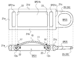
- FIG. 10 is a schematic longitudinal cross-sectional schematic diagram of a handle according to a third embodiment of the present invention, the elastic piece being along the two-dot chain line XIa-XI1 of FIG. 10, and the handle body being the two-dot chain line of FIG. It is along XIb-XIb.
- FIG. 9 is a schematic partial top view and a cross-sectional schematic view in the width direction showing an attachment aspect of an elastic piece to a pull main body in a pull handle according to a third embodiment of the present invention, and a cross-sectional schematic diagram on the left side of the drawing is taken along a dashed line XIIIa-XIIIa
- the schematic cross-sectional view on the right side of the drawing is taken along the alternate long and short dash line XIIIb-XIIIb.
- FIG. 6 is a schematic top view of a pull handle main body according to a fourth embodiment of the present invention, and a schematic longitudinal sectional view of the pull handle after attachment of an elastic piece to the pull main body. It is a schematic exploded longitudinal cross-sectional view of the handle according to the fifth embodiment of the present invention, and is a view for explaining an attachment mode of the elastic piece to the handle main body. It is a schematic longitudinal cross-sectional view of the handle concerning 5th Embodiment of this invention, and is a figure for demonstrating the attachment aspect of the elastic piece with respect to a handle main body. It is a schematic top view of the pull main body of the pull handle which concerns on 5th Embodiment of this invention.
- the reference drawings are mainly intended for explanation of the invention and are simplified as appropriate.
- a center line CL is set as appropriate.
- the center line CL is an axis line that coincides with the longitudinal direction of the handle and is positioned on the center in the width direction of the handle.
- the longitudinal direction and the width direction of the handle are directions orthogonal to each other, and in the following description, the longitudinal direction may be understood as the vertical direction / vertical direction, and the width direction may be understood as the horizontal direction / horizontal direction.
- the direction close to the center line CL is referred to as the inside, and the direction away from the center line CL is referred to as the outside.
- the front and back of the frame-like handle will be described as the front and back directions.
- the front and back direction of the handle is a direction that coincides with the thickness direction of the frame of the handle and is orthogonal to the above-described longitudinal and width directions.
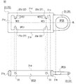
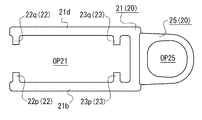
- FIG. 1 is a schematic top view and longitudinal side view of a handle.
- FIG. 2 is a schematic top view and a longitudinal cross-sectional schematic view of a pull handle main body.
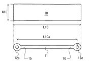
- FIG. 3 is a schematic top view and longitudinal side view of the elastic piece of the handle.
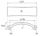
- FIG. 4 is a schematic top view and a longitudinal side view of the elastic piece after being attached to the handle main body.
- FIG. 5 is a schematic partial top view and a cross-sectional schematic view in the width direction showing how the elastic piece is attached to the pulling body.
- FIG. 6 is a schematic longitudinal sectional view for explaining repetitive movement of the elastic piece of the handle.
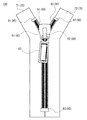
- FIG. 7 is a schematic view showing a slide fastener having a handle.
- the pull handle 50 is a long body having a base end 51 and a top end 52 to be attached to the fastener slider, and is configured by attaching the elastic piece 10 to the pull handle body 20.
- the elastic piece (pressed member) 10 is detachable from the main body 20.
- the handle main body 20 is typically made of metal, but may be made of resin.
- the elastic piece 10 is typically made of rubber, but may be any elastic material that can be elastically deformed.
- the elastic piece 10 is made of silicone rubber, polybutadiene-based, nitrile-based, or chloroprene-based synthetic rubber, natural rubber, or the like.
- the handle main body 20 includes a rectangular frame 21 in a top view and a mounting ring 25 protruding from the outer peripheral side surface of the frame 21.
- the frame body 21 is a part to be gripped by the finger of the pulling gripper, and the attachment ring 25 is a part to be attached to the fastener slider, typically the attachment pillar.
- the frame body 21 is a closed frame body, and an opening OP21 is formed there.
- the opening OP21 of the frame 21 is a space in which the elastic piece 10 is arranged, and allows the front and back repetitive movement of the elastic piece 10 schematically shown in the lower part of FIG. 1 and FIG.
- the attachment ring 25 is also configured as a closed ring, and the attachment column of the fastener slider is inserted into the hole OP25 of the attachment ring 25.
- the frame body 21 is a flat closed frame having a pair of a front surface (opposing surface) 21p and a back surface (opposing surface) 21q arranged in parallel and facing each other, and has a thickness defined by the front surface 21p and the back surface 21q.
- the frame body 21 is elongated along the center line CL and is symmetric with respect to the center line CL.
- the frame body 21 includes a top end collar part 21a, a first long bar part 21b, a base end collar part 21c, and a second long bar part 21d that are continuously formed in this order so as to form a rectangle.
- the top end collar 21 a and the base end collar 21 c extend in parallel to the width direction of the handle 50.
- the first long bar portion 21b and the second long bar portion 21d extend in parallel to the longitudinal direction of the handle 50 and connect the left and right ends of the top end collar 21a and the left and right ends of the base end collar 21c.
- the opening OP21 of the frame body 21 is also elongated in the same direction as the outer shape of the frame body 21, and the length L34 of the opening OP21 in the longitudinal direction is longer than the width W21 of the opening OP21.
- the arrangement direction of the front surface 21p and the back surface 21q of the frame body 21 is equal to the thickness direction of the frame body 21.
- the frame body 21 has a pair of a top end side shaft portion (shaft portion) 22 and a base end side shaft portion (shaft portion) 23, which are arranged at a predetermined interval L32 along the longitudinal direction of the handle 50.
- the top end side shaft portion 22 and the base end side shaft portion 23 are both cylindrical, and the interval L32 between the top end side shaft portion 22 and the base end side shaft portion 23 is the interval between the central axes of the respective cylinders.
- the top end side shaft portion 22 has a central axis AX2 that coincides with the width direction of the handle 50, and is a virtual cylindrical shape that connects the first long rod portion 21b and the second long rod portion 21d along the central axis AX2. This is the portion that remains after the center of the shaft is removed.
- the top end side shaft portion 22 protrudes inward from the top end side first columnar portion 22p that protrudes inward from the inner side surface of the first long rod portion 21b and the inner side surface of the second long rod portion 21d.
- the top end side second cylindrical portion 22q is provided, and the top end side first cylindrical portion 22p and the top end side second cylindrical portion 22q are arranged coaxially.
- the top end side first columnar portion 22p and the top end side second columnar portion 22q are provided at the center of the thickness of the frame body 21 of the pull main body 20.
- the base end side shaft portion 23 also has the same configuration as the top end side shaft portion 22.
- it has center axis AX4 instead of center axis AX2
- it has base end side 1st cylindrical part 23p instead of top end side 1st cylindrical part 22p, it replaces with top end side 2nd cylindrical part 22q, and is proximal It has a side second cylindrical portion 23q.
- each protrusion height H22 of the top end side first columnar portion 22p and the top end side second columnar portion 22q, and each protrusion height H23 of the base end side first columnar portion 23p and the base end side second columnar portion 23q are shown in FIG.
- H22 H23
- TH21> R22 and TH21> R23 are satisfied.
- the thickness TH25 of the mounting ring 25 projecting from the outer surface of the base end collar 21c gradually decreases from the front and back of the mounting ring 25 as the mounting ring 25 is separated from the frame body 21 side.
- the specific shape of the elastic piece 10 attached to the pulling body 20 is arbitrary, and various shapes such as a rectangle, a circle, a triangle, and a star shape are conceivable, but at least a long member that is long in a predetermined direction is elastic. It is desirable to construct the piece 10. Thereby, when the elastic piece 10 is attached to the pull main body 20 in a state compressed in the longitudinal direction, the elastic piece 10 can be appropriately warped to the front or back side of the pull main body 20, and A comfortable pressing feeling can be ensured. In order to ensure design uniformity, it is more desirable to make the longitudinal direction of the elastic piece 10 coincide with the longitudinal direction of the handle body 20.
- the elastic piece 10 It is desirable to make the elastic piece 10 freely movable on the puller body 20. Thereby, the distraction feeling by the repetitive motion of the elastic piece 10 can be provided to the handle gripper.
- the repetitive movement of the elastic piece 10 is repeated between a state in which the elastic piece 10 is bent in a convex shape toward the front side of the handle body 20 and a state in which the elastic piece 10 is bent in a convex shape on the back side with reference to the front and back sides of the handle body 20. It means that you can exercise.
- the movement mode of the elastic piece 10 is not necessarily limited to this.
- the elastic piece 10 may be configured so as to always maintain a state of being bent in a convex shape toward the front side of the handle body 20, and conversely, a state in which the elastic piece 10 is bent in a convex shape toward the back side of the handle body 20. May always be maintained. Even in such a case, a comfortable pressing feeling of the elastic piece 10 can be provided to the gripper.
- the elastic piece 10 includes a flat plate portion (intermediate portion) 11 having a certain thickness, and a columnar top end side end portion (opposing end portion) provided at both ends of the flat plate portion 11. 12a and a base end side end (opposite end) 12c.
- the top end side end portion 12a and the base end side end portion 12c are fixed to the handle body 20, and a flat plate portion is provided between the top end side end portion 12a and the base end side end portion 12c.
- 11 extends in an arc shape and warps in a convex shape from the inside of the frame 21 to the outside of the frame.
- the top end side end portion 12a and the base end side end portion 12c of the elastic piece 10 are grasped as position fixing portions that are fixed in relation to the handle body 20 when the elastic piece 10 is attached to the handle body 20, and the flat plate of the elastic piece 10
- the portion 11 is grasped as the above-mentioned position fixing portion, that is, an arc-shaped extending portion that should extend in an arc shape between the top end portion 12 a and the proximal end portion 12 c. It doesn't matter.
- Cylindrical recesses 15 are provided on the left and right side surfaces of the top end side end portion 12a, respectively, and the top end side first columnar portion 22p and the top end side second columnar portion 22q of the top end side shaft portion 22 are provided. Inserted individually.
- cylindrical recesses 16 are respectively provided on the left and right side surfaces of the base end portion 12c, and the base end side first column portion 23p of the base end side shaft portion 23 and the base portion are provided. The end side second cylindrical portion 23q is individually inserted.
- the mode of fitting between the elastic piece 10 and the frame body 21 is arbitrary, and the relationship between the convex portion and the concave portion may be reversed.
- the length of the elastic piece 10 is a length L10 as shown in FIG. 3 when uncompressed before being attached to the handle body 20, but as shown in FIG. 4 when compressed after being attached to the handle body 20.
- the length Ls10 is shorter than the length L10.
- an interval L10a between the top end side end portion 12a and the base end side end portion 12c of the elastic piece 10 is an interval Ls10a narrower than the interval L10a as shown in FIG. Become.
- the width W10 of the elastic piece 10 is the distance W22 between the top end side first cylindrical portion 22p and the top end side second cylindrical portion 22q shown in FIG. 2 and between the base end side first cylindrical portion 23p and the base end side second cylindrical portion 23q. Accordingly, the top end side end portion 12a of the elastic piece 10 can be suitably attached to the top end side shaft portion 22 of the frame body 21.
- the finger which pushed in the elastic piece 10 touches the 1st elongate bar part 21b and the 2nd elongate bar part 21d of the frame 21 after that, and can thereby define the stop position of a finger.
- the elastic piece 10 is prevented from being detached from the frame body 21 by suppressing the excessive pressing of the elastic piece 10 by the finger.
- the opening OP21 of the frame body 21 is substantially closed in the width direction by the elastic piece 10.
- the recesses 15 on the left and right side surfaces of the top end side end portion 12a of the elastic piece 10 are fitted into the top end side first cylindrical portion 22p and the top end side second cylindrical portion 22q, respectively.
- the recesses 16 on the left and right side surfaces of the base end side end portion 12c of the elastic piece 10 are fitted into the base end side first cylindrical portion 23p and the base end side second cylindrical portion 23q, respectively.
- the elastic piece 10 is attached to the frame body 21 in the manner shown as an example in FIG.
- the flat plate portion 11 is sandwiched from both sides in the frame body length.
- the flat plate portion 11 extends in an arc shape between the top end portion 12a and the base end portion 12c.
- the elastic piece 10 attached to the frame body 21 can freely change the direction of warping in the front and back directions of the pull body 20 perpendicular to the longitudinal direction and the width direction of the pull handle 50.
- the center in the longitudinal direction of the front surface 10 m and the back surface 10 n of the elastic piece 10 is higher than the front surface 21 p of the pulling body 20.
- the elastic piece 10 is elastically deformed, and as shown in the lower part of FIG.
- the center in the longitudinal direction of the front surface 10m and the back surface 10n of the elastic piece 10 is at a position lower than the back surface 21q of the pull main body 20.
- the handle 50 includes the handle body 20 including the frame body 21 and the elastic piece 10 made of an elastic material and disposed within the frame of the frame body 21 of the handle body 20.
- the elastic piece 10 is attached to the handle main body 20 in such a manner that the elastic piece 10 warps out from the inside of the frame 21 of the handle main body 20 to the outside of the frame.
- the elastic piece 10 that is warped out of the frame 21 of the pull body 20 from the inside of the frame body 21 can be pushed in with the finger of the pull gripper, and the pull gripper can feel the pressing of the elastic piece 10. Through this, it can be expected that the gripper grasper will try to distract.
- the design of the handle 50 can be improved by selecting the shape, color, material, and the like of the handle main body 20 and the elastic piece 10.
- the direction in which the elastic piece 10 warps in an arc shape can be freely changed, so that the handle holder can enjoy the operational feeling of the repetitive movement of the elastic piece 10.
- the elastic piece 10 can be attached to and detached from the handle body 20, so that the elastic piece can be replaced with respect to deterioration over time of the elastic piece 10 or unintentional loss of the elastic piece 10. Can be dealt with.
- the color selection of the elastic piece 10 can be left to the purchaser, and the commercial value can be increased from a design viewpoint. If the elastic piece 10 is attached to the pull main body 20 by fitting between the pull main body 20 and the elastic piece 10, the simple structure of the pull handle 50 can be maintained. If the longitudinal direction of the pull main body 20 and the longitudinal direction of the elastic piece 10 are matched, the appearance of the pull handle 50 can be made uniform.
- the slide fastener 100 includes a fastener slider 60, a set of fastener tapes 70 (71, 72), a set of fastener elements 80 (81, 82), and a stop 90 (a set of upper stoppers). 91, 92 and bottom stop 93).
- the slide fastener 100 includes a set of fastener stringers in which fastener elements 81 and 82 are fixed to fastener tapes 71 and 72.
- the slide fastener 100 is a long body having a long and constant width.
- a pair of fastener elements 81 and 82 are provided on the opposing inner edges of the pair of fastener tapes 71 and 72, and the fastener slider 60 is inserted through the pair of fastener elements 81 and 82. By sliding the fastener slider 60 along the fastener elements 81 and 82, the fastener elements 81 and 82 can be engaged and separated.
- Fastener tapes 71 and 72 constituting the fastener stringer are woven fabric, knitted fabric, or non-woven fabric, but are not limited thereto, and may be other arbitrary sheet-like members.
- Fastener elements 81 and 82 are composed of continuous coils, and are fixed to the inner ends of the fastener tapes 71 and 72 by sewing.
- the meshing portions of the fastener elements 81 and 82 are portions that mainly protrude from the fastener tapes 71 and 72.
- the meshing portions of the fastener elements 81 and 82 have a wide line width due to the deformation, thereby ensuring the meshing of the fastener elements.
- the fastener elements 81 and 82 are not limited to such a coil form, and may be a row of individually separated engagement elements (metal engagement elements, resin engagement elements, etc.).
- the top stoppers 81 and 82 are general ones and are provided corresponding to the set of fastener elements 81 and 82. Each top stopper is fixed to the front and back surfaces of the fastener tapes 71 and 72 so as to sandwich the inner ends of the fastener tapes 71 and 72.
- the bottom stop 93 is a general one, and is fixed across a set of fastener tapes 71 and 72 so as to cover the set of fastener elements 81 and 82.
- the fastener slider 60 is a general slider in which the above-described handle 50 is attached to the handle attachment column (the handle attachment portion) 62 of the slider body 61.
- the upper blade plate and the lower blade plate are connected by a connecting column, and a Y-shaped element guide path is provided between the upper blade plate and the lower blade plate.
- the handle 50 is rotatably provided on the upper wing plate.
- the slide fastener 100 can be opened and closed by raising or lowering the handle 50.
- FIG. 8 is a schematic top view of the handle body of the handle.
- FIG. 9 is a schematic top view of the handle body of the handle.
- the opening OP21 of the frame body 21 of the pull handle body 20 is not closed but is opened, but even in such a case, the same effect as in the first embodiment can be obtained.
- the top end collar 21 a described in the first embodiment is removed from the frame body 21.
- the first long rod portion 21b and the second long rod portion 21d may be shortened so as to eliminate the protrusion of the top ends of the first long rod portion 21b and the second long rod portion 21d. .
- the frame body 21 does not need to be a closed frame.
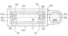
- FIG. 10 is a schematic top view schematically showing the handle.
- FIG. 11 is a schematic longitudinal cross-sectional view of a handle.
- FIG. 12 is a schematic top view and a longitudinal cross-sectional schematic view of the pull handle body.
- FIG. 13 is a schematic partial top view and a schematic cross-sectional view in the width direction showing how the elastic piece is attached to the puller body.
- the cross-sectional schematic diagram is along the alternate long and short dash line XIIIb-XIIIb.
- the elastic piece 10 is attached to the pull main body 20 by fitting the pull main body 20 and the elastic piece 10, but the specific mode of the fitting is different. Even in such a case, the same effect as the first embodiment can be obtained.
- the handle main body 20 has a top end side shaft portion (shaft portion) 22 and a base end side shaft portion (shaft portion) 23, and the top end side shaft portion 22 is the frame body 21.
- the opening OP21 it connects with the top end collar part 21a via the connecting rod 22k
- the base end side axial part 23 is connected with the base end collar part 21c in the opening OP21 of the frame 21 via the connecting rod 23k.
- the top end side shaft portion 22 and the connecting rod 22k constitute a T-shaped top end side mounting structure
- the base end side shaft portion 23 and the connecting rod 23k constitute a T-shaped base end side mounting structure.
- a notch portion 13 a is provided in the center of the top end side end portion 12 a of the elastic piece 10 in the width direction, and the left side holding portion 12 p that holds the left end of the top end side shaft portion 22 and the top end side shaft portion 22.
- a right holding portion 12q that holds the right end is provided.
- a left side recess 12p1 that receives the left end of the top end side shaft portion 22 is provided on the left side surface of the notch portion 13a, and a right side recess 12q1 that receives the right end of the top end side shaft portion 22 is provided on the right side surface of the notch portion 13a.
- the width direction of the elastic piece / the extending direction of the top end side or the base end side shaft portion is grasped as the left-right direction, and the lower side is grasped as the left side and the upper side is regarded as the right side as viewed in FIG. ing.
- the base end side end 12c of the elastic piece 10 is provided with the same structure as the top end side end 12a.
- a notch 13c is provided instead of the notch 13a
- a left holding part 12m is provided instead of the left holding part 12p
- a right holding part 12n is provided instead of the right holding part 12q.
- a left recess 12m1 is provided instead of the left recess 12p1
- a right recess 12n1 is provided instead of the right recess 12q1.
- FIG. 14 is a schematic top view of a pull handle main body and a schematic longitudinal sectional view of the pull handle after the elastic piece is attached to the pull main body.
- the pulling body 20 and the elastic piece 10 are not fitted to each other as in the above-described embodiment, but the elastic piece 10 is sewn to the pulling body 20 to be elastic with respect to the pulling body 20.
- the piece 10 is attached. Even in such a case, the elastic piece 10 can be axially attached to the handle main body 20 similarly to the above-described embodiment, and the same effect as the above-described embodiment can be obtained.
- the top end side shaft portion 22 and the base end side shaft portion 23 provided on the frame body 21 of the pull handle body 20 are formed by the first long rod portion 21 b and the second long rod portion 21 d.
- the handle 50 is continuous in the width direction, and the center of the handle 50 in the width direction is not discontinuous as compared with the first embodiment.
- the elastic piece 10 has a top end side end portion 12 a and a base end side end portion 12 c that are flat, and is configured in a cylindrical shape when viewed from the side as in the first embodiment. It has not been.
- the top end side end portion 12 a of the elastic piece 10 is wound around the top end side shaft portion 22 of the frame body 21 and is sewn by the sewing thread 17.
- the base end side end portion 12 c of the elastic piece 10 is wound around the base end side shaft portion 23 of the frame body 21 and is sewn by the sewing thread 18.
- FIG. 15 is a schematic exploded longitudinal sectional view of a handle, and is a view for explaining an attachment mode of an elastic piece to the handle main body.
- FIG. 16 is a schematic longitudinal cross-sectional view of the handle, and is a view for explaining an attachment mode of the elastic piece to the handle main body.
- FIG. 17 is a schematic top view of a pull handle main body.
- FIG. 18 is a schematic top view of the handle, and shows a state after the elastic piece is attached to the handle main body.
- the elastic piece 10 is attached to the pull main body 20 by partially sandwiching the elastic piece 10 by the components of the pull main body 20. Even in such a case, the same effects as those of the above-described embodiment can be obtained.
- the top end side end 12 a of the elastic piece 10 has a flat plate shape and is not configured in a cylindrical shape in a side view.
- the frame body 21 of the handle main body 20 is provided with a holding structure 40 that holds the elastic piece 10 in between.
- the holding structure 40 includes a pedestal portion 41 provided in the frame body 21 so as to close the top end side of the opening OP21 of the frame body 21, and a cover portion 42 that is separate from the frame body 21.
- Steps are provided on each facing surface of the pedestal portion 41 and the cover portion 42, and the pedestal portion 41 has a high step surface 41p, a step side surface 41r, and a low step surface 41q. It has a high step surface 42p, a step surface 42r, and a low step surface 42q.
- the high step surface 41p of the pedestal portion 41 and the high step surface 42p of the cover portion 42 are in surface contact, and fixing, for example, screw fixing or the like is performed in this range.
- An interval less than the thickness of the top end side end portion 12a of the elastic piece 10 is provided between the low step surface 41q of the pedestal portion 41 and the low step surface 42q of the cover portion 42, whereby the pedestal portion 41 and the cover portion are arranged.
- the top end side end 12 a of the elastic piece 10 can be suitably pressed and held between 42.
- the position control part which position-controls the top end side edge part 12a of the elastic piece 10 in cooperation with the level
- the flat plate portion 11 of the elastic piece 10 extends in an arc shape as in the above-described embodiment.
- the top end side end portion 12 a of the elastic piece 10 is placed on the pedestal portion 41, and the base end side end portion 12 c of the elastic piece 10 is fitted to the base end side shaft portion 23.
- the cover portion 42 is placed on the top end side end portion 12a of the elastic piece 10, and the cover portion 42 is fixed to the pedestal portion 41 with the screws 29, whereby the state shown in FIG.
- FIG. 19 is a schematic exploded longitudinal sectional view of a handle, and is a view for explaining an attachment mode of an elastic piece to the handle main body.
- FIG. 20 is a schematic top view of the handle, and shows a state after the elastic piece is attached to the handle main body.
- the holding structure 40 of the fifth embodiment is also applied to the proximal end side of the pull body 20, that is, the elastic piece 10 is sandwiched and held on both the top end side and the proximal end side of the pull body 20. Even in such a case, the same effects as those of the above-described embodiment can be obtained.
- the base end side end portion 12c of the elastic piece 10 has a flat plate shape, that is, is not configured in a cylindrical shape in a side view.
- the frame body 21 of the handle main body 20 is further provided with a holding structure 45 for sandwiching and holding the elastic piece 10.
- the holding structure 45 includes a pedestal portion 46 that protrudes from the inner surface of the proximal end flange portion 21 c of the frame body 21, and a cover portion 47 that is separate from the frame body 21. Steps are provided on the opposing surfaces of the pedestal 46 and the cover 47, and this is the same as in the fifth embodiment.
- the proximal end 12c of the elastic piece 10 is suitably pressed and held between the pedestal 46 and the cover 47.
- the step side surface of the pedestal portion 46 and the step side surface of the cover portion 47 cooperate to constitute a position restricting portion that restricts the position of the proximal end 12c of the elastic piece 10.
- the cover portion may be fixed to the pedestal portion using screws 29.
- FIG. 21 is a schematic exploded longitudinal sectional view of a handle, and is a view for explaining an attachment mode of an elastic piece to the handle main body.
- the elastic piece 10 is curved in an arc shape before the elastic piece 10 is fixed to the handle body 20. Therefore, after the elastic piece 10 is attached to the pulling body 20, even if the elastic piece 10 is pushed into the back side of the frame body 21, the elastic piece 10 returns to a state of being bent convexly toward the front side of the frame body 21. There is no transition to a state of convexly warping to the back side.
- the specific shape, material, etc. of the handle main body are arbitrary.
- the specific shape, material, etc. of the elastic piece are arbitrary.
- the fitting mode of the elastic piece and the handle main body is arbitrary, and the elastic piece may be provided with a convex portion and the puller main body may be provided with a concave portion.
- Reference signs included in the claims are for reference only and should not be referenced for the purpose of limiting the scope of the claims.
- the frame body 21 may have a circular shape such as a circle or an ellipse
- the shaft portions 22 and 23 may be provided on the inner surface of the ring
- the elastic piece 10 may be attached thereto.
- the elastic piece 10 may be formed by covering a metal plate with resin or rubber.
Landscapes
- Slide Fasteners (AREA)
Abstract
ファスナースライダー(60)に対して取り付けられるべき引手(50)は、枠体(21)を含む引手本体(20)と、弾性材料から成り、引手本体(20)の枠体(21)内に配置される被押圧部材(10)と、を備える。被押圧部材(10)は、引手本体(20)の枠体(21)の枠内から枠外へ孤状に反り出る態様にて引手本体(20)に対して取り付けられる。
Description
本発明は、引手、ファスナースライダー、及びスライドファスナーに関し、特に弾性の被押圧部材を備える引手に関する。
スライドファスナーは、鞄、財布、衣類、袋類等の多種多様な物品に用いられ、ファッション性に富む物品に用いられることも多い。このような観点からスライドファスナーとしても、「デザイン性」、「面白さ/目新しさ」といった観点からの様々な提案が期待されている。
特許文献1には、同文献の図2に示すように、スライダー胴体Sに対して紐体4を装着することに適する引手連結具が開示されている。この引手連結具は、同文献の図1に示す構造を有し、同文献の図3に示すように引手連結具に対して紐体4が通される。同文献の図8乃至図10には、紐体4の端部を挟着具20で固定することも開示されている。
遊び心のある引手を簡素な構成で実現することが望まれている。
本発明に係る引手は、ファスナースライダーに対して取り付けられるべき引手であって、枠体を含む引手本体と、弾性材料から成り、前記引手本体の前記枠体内に配置される被押圧部材と、を備え、前記被押圧部材は、前記引手本体の前記枠体の枠内から枠外へ孤状に反り出る態様にて前記引手本体に対して取り付けられる。引手本体の枠体の枠内から枠外へ孤状に反り出た被押圧部材を引手把持者の指で押し込むことができ、遊び心のある引手を簡素な構成で実現することができる。
前記被押圧部材が弧状に反り出る向きが変更自在である、と良い。引手把持者は、被押圧部材の反復運動の操作感を楽しむことができる。
前記被押圧部材が前記引手本体に対して着脱可能である、と良い。引手の組立が簡便であり、交換容易性も確保できる。
前記引手本体と前記被押圧部材間の嵌合により前記引手本体に対して前記被押圧部材が装着される、と良い。引手の組立が簡便である。
前記被押圧部材が一組の対向端部と当該一組の対向端部間の中間部を備える長尺部材であり、前記一組の対向端部夫々が前記引手本体に対して取付固定され、前記中間部が前記一組の対向端部間を弧状に延在する、と良い。被押圧部材を好適に弧状に反らせることができる。
前記枠体が、前記被押圧部材の前記一組の対向端部が嵌合される一組の軸部を備える、と良い。被押圧部材を枠体に簡単に装着できる。
前記引手本体及び前記被押圧部材が同一方向に長尺である、と良い。
本発明に係るファスナースライダーは、上述の引手と、前記引手が取り付けられる引手取付部を有するスライダー本体と、を備える。
本発明に係るスライドファスナーは、上述のファスナースライダーを備える。
本発明によれば、遊び心のある引手を簡素な構成で実現することができる。
以下、図面を参照しつつ、本発明の実施の形態について説明する。各実施形態は、個々に独立したものではなく、過剰説明をするまでもなく、当業者をすれば、適宜、組み合わせることが可能であり、この組み合わせによる相乗効果も把握可能である。実施形態間の重複説明は、原則的に省略する。
参照図面は、発明説明を主目的とするものであり、適宜、簡略化されている。これらの図においては、適宜、中心線CLが設定されている。中心線CLは、引手の長手方向に一致し、かつ引手の幅方向中央上に位置する軸線である。なお、引手の長手方向と幅方向は互いに直交する方向であり、以下の説明においては、長手方向を縦方向/上下方向とし、幅方向を横方向/左右方向として把握する場合がある。説明の便宜上、中心線CLに近接する方向を内側と呼び、中心線CLから離間する方向を外側と呼ぶ。説明の便宜上、枠状の引手の表裏を表裏方向として説明する。引手の表裏方向は、引手の枠の厚み方向に一致し、上述の各長手方向及び幅方向に対して直交する方向である。
<第1実施形態>
図1乃至図7を参照して第1実施形態について説明する。図1は、引手の概略的な上面図及び長手側面図である。図2は、引手の引手本体の概略的な上面図及び長手断面模式図である。図3は、引手の弾性片の概略的な上面図及び長手側面図である。図4は、引手本体に対する取付後の弾性片の概略的な上面図及び長手側面図である。図5は、引手本体に対する弾性片の取付態様を示す概略的な部分上面図及び幅方向断面模式図である。図6は、引手の弾性片の反復運動を説明するための概略的な長手断面模式図である。図7は、引手を有するスライドファスナーを示す概略図である。
図1乃至図7を参照して第1実施形態について説明する。図1は、引手の概略的な上面図及び長手側面図である。図2は、引手の引手本体の概略的な上面図及び長手断面模式図である。図3は、引手の弾性片の概略的な上面図及び長手側面図である。図4は、引手本体に対する取付後の弾性片の概略的な上面図及び長手側面図である。図5は、引手本体に対する弾性片の取付態様を示す概略的な部分上面図及び幅方向断面模式図である。図6は、引手の弾性片の反復運動を説明するための概略的な長手断面模式図である。図7は、引手を有するスライドファスナーを示す概略図である。
図1に示すように、引手50は、ファスナースライダーに対して取り付けられるべき基端51と頂端52を有する長尺体であり、引手本体20に対して弾性片10が装着して構成され、引手本体20に対して弾性片(被押圧部材)10が着脱可能な状態にある。引手本体20は、典型的には金属製であるが、樹脂製としても構わない。弾性片10は、典型的にはゴム製であるが、弾性変形可能な弾性材料であれば任意である。例示的には、弾性片10は、シリコーンゴム、ポリブタジエン系、ニトリル系、又はクロロプレン系の合成ゴム、又は天然ゴム等から成る。
図1及び図2に示すように、引手本体20は、上面視して矩形状の枠体21、及び枠体21の外周側面に突設した取付環25を有する。枠体21は、引手把持者の指により把持されるべき部分であり、取付環25は、ファスナースライダー、代表的にはその取付柱に対して取り付けられるべき部分である。枠体21は、閉じた枠体であり、そこに開口OP21が形成されている。枠体21の開口OP21は、弾性片10が配置される空間であり、図1の下部分及び図6に模式的に示す弾性片10の表裏反復運動を許容する。取付環25も閉じた環として構成され、取付環25の孔OP25へファスナースライダーの取付柱が挿通される。
枠体21は、平行に対向配置した一組の表面(対向面)21pと裏面(対向面)21qを有する平板状の閉じた枠であり、表面21pと裏面21qにより規定される厚みを有する。枠体21は、中心線CLに沿って長尺、かつ中心線CLに関して対称に構成される。枠体21は、詳細には、頂端杆部21a、第1長尺棒部21b、基端杆部21c、及び第2長尺棒部21dが矩形を為すべくこの順に連続して構成される。頂端杆部21aと基端杆部21cは、引手50の幅方向に平行に延在する。第1長尺棒部21bと第2長尺棒部21dは、引手50の長手方向に平行に延在し、頂端杆部21aの左右両端と基端杆部21cの左右両端間を連結する。枠体21の開口OP21も枠体21の外形と同方向に長尺であり、長手方向の開口OP21の長さL34が開口OP21の幅W21よりも長い。なお、枠体21の表面21pと裏面21qの配置方向は、枠体21の厚み方向に等しい。
枠体21は、一組の頂端側軸部(軸部)22と基端側軸部(軸部)23を有し、これらは引手50の長手方向に沿って所定間隔L32をあけて配置される。頂端側軸部22と基端側軸部23はともに円柱状であり、頂端側軸部22と基端側軸部23間の間隔L32は、各円柱の中心軸間の間隔である。
頂端側軸部22は、引手50の幅方向に一致する中心軸AX2を有し、中心軸AX2沿いに第1長尺棒部21bと第2長尺棒部21d間を接続する仮想の円柱状軸部の中央が除去されて残存した部分である。端的には、頂端側軸部22は、第1長尺棒部21bの内側面から内側へ突出した頂端側第1円柱部22pと、第2長尺棒部21dの内側面から内側へ突出した頂端側第2円柱部22qを有し、頂端側第1円柱部22pと頂端側第2円柱部22qとは同軸配置されている。頂端側第1円柱部22pと頂端側第2円柱部22qは、引手本体20の枠体21の厚み中央に設けられている。
基端側軸部23も頂端側軸部22と同様の構成を有する。なお、中心軸AX2に代えて、中心軸AX4を有し、頂端側第1円柱部22pに代えて基端側第1円柱部23pを有し、頂端側第2円柱部22qに代えて基端側第2円柱部23qを有する。
頂端側第1円柱部22pと頂端側第2円柱部22qの各突出高さH22と基端側第1円柱部23pと基端側第2円柱部23qの各突出高さH23については、図2から明らかなようにH22=H23を満足する。頂端側第1円柱部22pと頂端側第2円柱部22q間の間隔W22と基端側第1円柱部23pと基端側第2円柱部23q間の間隔W23についても同様にW22=W23を満足する。頂端側第1円柱部22pと頂端側第2円柱部22qの直径R22と基端側第1円柱部23pと基端側第2円柱部23qの直径R23については、図1から明らかなようにR22=R23を満足する。
図1の下部分に示す枠体21の厚みTH21と直径R22、R23の関係については、TH21>R22、TH21>R23を満足する。基端杆部21cの外側面に突設した取付環25の厚みTH25は、取付環25が枠体21側から離間するに応じて取付環25の表裏から徐々に狭くなる。
引手本体20に対して取り付けられる弾性片10の具体的形状は任意であり、矩形、円形、三角形、星形等の様々な形状が考えられるが、少なくとも所定方向に長尺の長尺部材で弾性片10を構成することが望ましい。これにより、その長手方向に圧縮された態様で弾性片10を引手本体20に取り付けると、引手本体20の表又は裏側へ弾性片10を適当に反らせることができ、引手把持者による弾性片10の心地よい押込み感覚を確保することができる。意匠的な統一性を確保するために、引手本体20の長手方向に弾性片10の長手方向を一致させることがより望ましい。
引手本体20上において弾性片10を反復運動自在とすることが望ましい。これにより、弾性片10の反復運動による気晴らし感を引手把持者に提供することができる。弾性片10の反復運動は、引手本体20の表裏を基準として、弾性片10が引手本体20の表側へ凸状に反った状態とその裏側へ凸状に反った状態との間で反復的に運動可能なことを意味する。しかしながら、弾性片10の運動態様は、必ずしもこの限りではない。例えば、弾性片10が、引手本体20の表側へ凸状に反った状態を常に維持するように構成されていても良く、これとは逆に、引手本体20の裏側へ凸状に反った状態を常に維持するように構成されても良い。このような場合であっても、弾性片10の心地よい押込み感覚を把持者に提供することができる。
弾性片10は、図3及び図4に示すように、一定厚の平板部(中間部)11、及び平板部11の両端に設けられた側面視円柱状の頂端側端部(対向端部)12aと基端側端部(対向端部)12cを具備する。枠体21に対して弾性片10を装着すると、頂端側端部12aと基端側端部12cが引手本体20に位置固定され、頂端側端部12aと基端側端部12c間を平板部11が弧状に延在して枠体21の枠内から枠外へ凸状に反り出る。弾性片10の頂端側端部12aと基端側端部12cを引手本体20に対する弾性片10の装着時に引手本体20との関係において位置固定される位置固定部として把握し、弾性片10の平板部11を引手本体20に対する弾性片10の装着時に上述の位置固定部、端的には頂端側端部12aと基端側端部12c間を弧状に延在するべき弧状延在部と把握しても構わない。
頂端側端部12aの左右側面には、各々、円柱状の凹部15が設けられており、これらに対して頂端側軸部22の頂端側第1円柱部22pと頂端側第2円柱部22qが個別に挿入される。同様に、基端側端部12cの左右の側面には、各々、円柱状の凹部16が設けられており、これらに対して基端側軸部23の基端側第1円柱部23pと基端側第2円柱部23qが個別に挿入される。なお、弾性片10と枠体21間の嵌合の態様は任意であり、凸部と凹部の関係を逆転させても構わない。
弾性片10の長さは、引手本体20への取付前の非圧縮時、図3に示すように長さL10であるが、引手本体20への取付後の圧縮時、図4に示すように長さL10よりも短い長さLs10になる。同様に、弾性片10の頂端側端部12aと基端側端部12c間の間隔L10aが、引手本体20への取付後の圧縮時、図4に示すように間隔L10aよりも狭い間隔Ls10aとなる。
弾性片10の幅W10は、図2に示す頂端側第1円柱部22pと頂端側第2円柱部22q間の間隔W22及び基端側第1円柱部23pと基端側第2円柱部23q間の間隔W23と比較して適当に広く、これにより、枠体21の頂端側軸部22に対して弾性片10の頂端側端部12aを好適に装着することができる。
弾性片10の幅W10と枠体21の開口OP21の幅W21を対比すると、W21/W10=1.1~1.5を満足し、より好ましくはW21/W10=1.2~1.4を満足する。これにより、弾性片10を押し込んだ指が、その後、枠体21の第1長尺棒部21bと第2長尺棒部21dに当接し、これにより、指の停止位置を規定できる。指による弾性片10の過度な押込みを抑制して枠体21からの弾性片10の離脱の抑制を期待できる。この場合、枠体21の開口OP21が弾性片10により幅方向において実質的に塞がれる。
図5に示すように、弾性片10の頂端側端部12aの左右側面の凹部15は、各々、頂端側第1円柱部22pと頂端側第2円柱部22qに嵌合される。弾性片10の基端側端部12cの左右の側面の凹部16は、各々、基端側第1円柱部23pと基端側第2円柱部23qに嵌合される。
図5に例示的に示す態様にて枠体21に対して弾性片10が装着される。頂端側軸部22に頂端側端部12aが取付固定され、基端側軸部23に基端側端部12cが取付固定されると、枠体長手において両側から挟み込まれるように平板部11が圧縮され、これにより、平板部11が頂端側端部12aと基端側端部12cの間で弧状に延在する。
図6から理解できるように、枠体21に装着された弾性片10は、引手50の長手方向及び幅方向に対して直交する引手本体20の表裏方向において反り出る向きが変更自在にある。図6の上部分に示すように表向きに弾性片10が反り出る時、弾性片10の表面10m及び裏面10nの長手方向中央が、引手本体20の表面21pよりも高い位置にある。図6の上部分に示す状態の弾性片10の長手方向中央を下方へ押すと、弾性片10が弾性変形し、図6の下部分に示すように弾性片10が裏側へ反り出し、このとき、弾性片10の表面10m及び裏面10nの長手方向中央が、引手本体20の裏面21qよりも低い位置にある。図6の下部分に示す状態の弾性片10の長手方向中央を上方へ押すと、弾性片10が弾性変形し、図6の上部分に示す元の状態に復帰する。
上述の説明から明らかなように、本実施形態に係る引手50は、枠体21を含む引手本体20と、弾性材料から成り、引手本体20の枠体21の枠内に配置される弾性片10とを備え、弾性片10は、引手本体20の枠体21の枠内から枠外へ孤状に反り出る態様にて引手本体20に対して取り付けられる。本構成によれば、引手本体20の枠体21の枠内から枠外へ孤状に反り出た弾性片10を引手把持者の指で押し込むことができ、引手把持者は弾性片10の押込み感覚を楽しむことができ、これを通じて引手把持者が気晴らしを図ることが期待できる。更に、引手本体20と弾性片10の各形状、色、材質等を選定することにより、引手50のデザイン性の向上も見込むことができる。
本実施形態においては、弾性片10が弧状に反り出る向きが変更自在であり、これにより、引手把持者は、弾性片10の反復運動の操作感を楽しむことができる。更に、本実施形態においては、引手本体20に対して弾性片10が着脱可能であり、これにより、弾性片10の経時的劣化或いは弾性片10の意図しない紛失等に対して弾性片の交換にて対処することができる。更に、弾性片10の色選択を購入者側に委ねることもでき、デザイン的な観点から商品価値を高めることができる。引手本体20と弾性片10間の嵌合により引手本体20に対して弾性片10を装着すれば引手50の簡素な構成を保つこともできる。引手本体20の長手方向と弾性片10の長手方向を一致させれば、引手50の外観に統一性を持たせることもできる。
最後に、図7を参照して引手50がファスナースライダー60に取付けられた状態のスライドファスナー100について説明する。図7に示すように、スライドファスナー100は、ファスナースライダー60、一組のファスナーテープ70(71、72)、一組のファスナーエレメント80(81、82)、及び止部90(一組の上止め91、92、及び下止め93)を有する。なお、スライドファスナー100は、ファスナーテープ71、72にファスナーエレメント81、82が固定された一組のファスナーストリンガーを含む。
スライドファスナー100は、長尺かつ一定幅を有する長尺体である。一組のファスナーテープ71、72の対向する内側縁部には、一対のファスナーエレメント81、82が設けられ、これに対してファスナースライダー60が挿通される。ファスナースライダー60をファスナーエレメント81、82に沿って摺動させることにより、各ファスナーエレメント81、82を噛み合わせ・分離させることができる。
ファスナーストリンガーを構成するファスナーテープ71、72は、織物、編物、又は不織布であるが、これに限らず、その他の任意のシート状部材であっても良い。
ファスナーエレメント81、82は、連続したコイルから成り、ファスナーテープ71、72の内側端部に縫着固定されている。ファスナーエレメント81、82の噛合部は、主としてファスナーテープ71、72から突出した部分である。ファスナーエレメント81、82の噛合部は、変形により線幅が広くなっており、これにより、ファスナーエレメント同士の噛み合わせが確保される。なお、ファスナーエレメント81、82は、このようなコイルの態様に限らず、個々に分離した噛合エレメント(金属製の噛合エレメント、樹脂製の噛合エレメント等)の列であっても構わない。
上止め81、82は、一般的なものであり、一組のファスナーエレメント81、82に対応して設けられる。各上止めは、ファスナーテープ71、72の内側端を挟み込むようにファスナーテープ71、72の表裏面に固定されている。下止め93は、一般的なものであり、一組のファスナーエレメント81、82を覆うように一組のファスナーテープ71、72に跨って固定されている。
ファスナースライダー60は、スライダー本体61の引手取付柱(引手取付部)62に対して上述の引手50が取り付けられた一般的なスライダーである。ファスナースライダー60は、上翼板と下翼板とが連結柱により連結され、上翼板と下翼板との間にY字状のエレメント案内路が設けられている。引手50は、上翼板上に回動自在に設けられている。引手50の引き上げ又は引き下げにより、スライドファスナー100を開閉できる。
<第2実施形態>
図8及び図9を参照して第2実施形態について説明する。図8は、引手の引手本体の概略的な上面図である。図9は、引手の引手本体の概略的な上面図である。
図8及び図9を参照して第2実施形態について説明する。図8は、引手の引手本体の概略的な上面図である。図9は、引手の引手本体の概略的な上面図である。
本実施形態においては、引手本体20の枠体21の開口OP21を閉じず、開いた状態とするが、このような場合であっても、第1実施形態と同様の効果を得ることができる。図8に示すように、第1実施形態で説明した頂端杆部21aが枠体21から除去されている。第1長尺棒部21bと第2長尺棒部21dの各頂端の突出を無くすべく、図9に示す如く第1長尺棒部21bと第2長尺棒部21dを短縮しても良い。このように枠体21は閉じた枠である必要はない。
<第3実施形態>
図10乃至図13を参照して第3実施形態について説明する。図10は、引手の概略的な上面模式図である。図11は、引手の概略的な長手断面模式図である。図12は、引手本体の概略的な上面図及び長手断面模式図である。図13は、引手本体に対する弾性片の取付態様を示す概略的な部分上面図及び幅方向断面模式図であり、紙面左側の断面模式図が一点鎖線XIIIa-XIIIaに沿うものであり、紙面右側の断面模式図が一点鎖線XIIIb-XIIIbに沿うものである。
図10乃至図13を参照して第3実施形態について説明する。図10は、引手の概略的な上面模式図である。図11は、引手の概略的な長手断面模式図である。図12は、引手本体の概略的な上面図及び長手断面模式図である。図13は、引手本体に対する弾性片の取付態様を示す概略的な部分上面図及び幅方向断面模式図であり、紙面左側の断面模式図が一点鎖線XIIIa-XIIIaに沿うものであり、紙面右側の断面模式図が一点鎖線XIIIb-XIIIbに沿うものである。
本実施形態においては、第1実施形態と同様、引手本体20と弾性片10の嵌合により引手本体20に弾性片10を装着するが、その嵌合の具体的態様が異なる。このような場合であっても第1実施形態と同様の効果を得ることができる。
図10乃至図13に示すように、引手本体20には、頂端側軸部(軸部)22と基端側軸部(軸部)23を有し、頂端側軸部22が枠体21の開口OP21内において頂端杆部21aに連結棒22kを介して連結し、基端側軸部23が、枠体21の開口OP21内において基端杆部21cに連結棒23kを介して連結している。なお、頂端側軸部22と連結棒22kによりT字状の頂端側取付構造が構成され、基端側軸部23と連結棒23kによりT字状の基端側取付構造が構成される。
図13に示すように、弾性片10の頂端側端部12aの幅方向中央には切欠部13aが設けられ、頂端側軸部22の左端を保持する左側保持部12pと頂端側軸部22の右端を保持する右側保持部12qが設けられる。切欠部13aの左側側面には頂端側軸部22の左端を受け入れる左側凹部12p1が設けられ、切欠部13aの右側側面には頂端側軸部22の右端を受け入れる右側凹部12q1が設けられる。なお、本説明においては弾性片の幅方向/頂端側又は基端側軸部の延在方向を左右方向として把握し、図13を正面視して下側を左側とし、上側を右側として把握している。
図13に示すように、弾性片10の基端側端部12cにも頂端側端部12aと同様の構造が設けられる。但し、切欠部13aに代えて切欠部13cが設けられ、左側保持部12pに代えて左側保持部12mが設けられ、右側保持部12qに代えて右側保持部12nが設けられる。左側凹部12p1に代えて左側凹部12m1が設けられ、右側凹部12q1に代えて右側凹部12n1が設けられる。
<第4実施形態>
図14を参照して第4実施形態について説明する。図14は、引手の引手本体の概略的な上面図と、引手本体に対する弾性片の取付後の引手の概略的な長手断面模式図である。
図14を参照して第4実施形態について説明する。図14は、引手の引手本体の概略的な上面図と、引手本体に対する弾性片の取付後の引手の概略的な長手断面模式図である。
本実施形態においては、上述の実施形態のように引手本体20と弾性片10を嵌合するのではなく、引手本体20に対して弾性片10を縫着することにより引手本体20に対して弾性片10を取り付ける。このような場合であっても上述の実施形態と同様に引手本体20に対して弾性片10を軸着することができ、上述の実施形態と同様の効果を得ることができる。本実施形態においては、上述の実施形態と比較して、引手本体20に対する弾性片10の縫着に手間がかかる点が危惧されるが、引手本体20からの弾性片10の離脱をより十分に抑止することが期待できる。
図14の上部分に示すように、引手本体20の枠体21に設けられる頂端側軸部22と基端側軸部23が、第1長尺棒部21bと第2長尺棒部21dの間で引手50の幅方向に連続しており、第1実施形態と比較して引手50の幅方向中央が不連続になっていない。図14の下部分に模式的に示すように、弾性片10は、頂端側端部12a及び基端側端部12cが平坦であり、第1実施形態のように側面視して円柱状に構成されていない。弾性片10の頂端側端部12aが枠体21の頂端側軸部22に対して巻かれて縫着糸17により縫着される。弾性片10の基端側端部12cが枠体21の基端側軸部23に対して巻かれて縫着糸18により縫着される。
<第5実施形態>
図15乃至図18を参照して第5実施形態について説明する。図15は、引手の概略的な分解長手断面図であり、引手本体に対する弾性片の取付態様を説明するための図である。図16は、引手の概略的な長手断面図であり、引手本体に対する弾性片の取付態様を説明するための図である。図17は、引手の引手本体の概略的な上面図である。図18は、引手の概略的な上面図であり、引手本体に対して弾性片の取付後の状態を示す。
図15乃至図18を参照して第5実施形態について説明する。図15は、引手の概略的な分解長手断面図であり、引手本体に対する弾性片の取付態様を説明するための図である。図16は、引手の概略的な長手断面図であり、引手本体に対する弾性片の取付態様を説明するための図である。図17は、引手の引手本体の概略的な上面図である。図18は、引手の概略的な上面図であり、引手本体に対して弾性片の取付後の状態を示す。
本実施形態においては、上述の実施形態とは異なり、引手本体20の構成部品による弾性片10の部分的な挟み込みにより、引手本体20に弾性片10を取り付ける。このような場合であっても上述の実施形態と同様の効果を得ることができる。
図15に示すように、第1実施形態と比較して、弾性片10の頂端側端部12aが平板状であり、側面視円柱状に構成されていない。引手本体20の枠体21には、弾性片10を挟み込み保持する保持構造40が設けられる。保持構造40は、枠体21の開口OP21の頂端側を塞ぐ態様で枠体21に設けられた台座部41と、枠体21とは別体のカバー部42を有する。
台座部41とカバー部42の各対向面には段差が設けられ、端的には、台座部41は、高段差面41p、段差側面41r、及び低段差面41qを有し、カバー部42は、高段差面42p、段差側面42r、及び低段差面42qを有する。台座部41の高段差面41pとカバー部42の高段差面42pとが面接触し、この範囲において固定、例えば、ネジ固定等が施される。台座部41の低段差面41qとカバー部42の低段差面42qとの間には、弾性片10の頂端側端部12aの厚み未満の間隔が設けられ、これにより、台座部41とカバー部42の間で弾性片10の頂端側端部12aを好適に押圧保持することができる。なお、台座部41の段差側面41rとカバー部42の段差側面42rとが協調して弾性片10の頂端側端部12aを位置規制する位置規制部が構成される。
図16に示すように、弾性片10の平板部11が上述の実施形態と同様に弧状に延在する。図17及び図18に示すように、台座部41上に弾性片10の頂端側端部12aを載置し、弾性片10の基端側端部12cを基端側軸部23に嵌合し、弾性片10の頂端側端部12a上にカバー部42を載置し、台座部41に対してカバー部42をネジ29により固定し、これにより、図16に示す状態になる。
<第6実施形態>
図19及び図20を参照して第6実施形態について説明する。図19は、引手の概略的な分解長手断面図であり、引手本体に対する弾性片の取付態様を説明するための図である。図20は、引手の概略的な上面図であり、引手本体に対して弾性片の取付後の状態を示す。
図19及び図20を参照して第6実施形態について説明する。図19は、引手の概略的な分解長手断面図であり、引手本体に対する弾性片の取付態様を説明するための図である。図20は、引手の概略的な上面図であり、引手本体に対して弾性片の取付後の状態を示す。
本実施形態においては、第5実施形態の保持構造40を引手本体20の基端側においても適用し、つまり、引手本体20の頂端側と基端側の両方で弾性片10を挟み込み保持する。このような場合であっても上述の実施形態と同様の効果を得ることができる。
図19に示すように、第5実施形態で説明した点に加えて、弾性片10の基端側端部12cも平板状であり、つまり側面視円柱状に構成されていない。引手本体20の枠体21には、弾性片10を挟み込み保持するための保持構造45が更に設けられる。保持構造45は、枠体21の基端杆部21cの内側面から突設した台座部46と、枠体21とは別体のカバー部47を有する。台座部46とカバー部47の各対向面には段差が設けられ、この点は第5実施形態と同様である。第5実施形態の説明と同様、台座部46とカバー部47の間で弾性片10の基端側端部12cが好適に押圧保持される。なお、台座部46の段差側面とカバー部47の段差側面とが協調して弾性片10の基端側端部12cを位置規制する位置規制部を構成する。図20に模式的に示すように、ネジ29を用いてカバー部を台座部に固定すれば良い。
<第7実施形態>
図21を参照して第7実施形態について説明する。図21は、引手の概略的な分解長手断面図であり、引手本体に対する弾性片の取付態様を説明するための図である。
図21を参照して第7実施形態について説明する。図21は、引手の概略的な分解長手断面図であり、引手本体に対する弾性片の取付態様を説明するための図である。
本実施形態においては、枠体21の表側に凸状の弧状を維持するように弾性片10には所定の内部応力が残存している。このような場合であっても上述の実施形態で説明した効果を得ることができる。図21に示すように、引手本体20に対して弾性片10を固定する前から弾性片10が弧状に湾曲している。従って、引手本体20に弾性片10を取り付けた後、枠体21の裏側へ弾性片10を押し込んでも弾性片10は枠体21の表側へ凸状に反った状態へと戻り、枠体21の裏側へ凸状に反った状態へは遷移しない。
上述の教示を踏まえると、当業者をすれば、各実施形態に対して様々な変更を加えることができる。引手本体の具体的な形状、材質等は任意である。弾性片の具体的な形状、材質等は任意である。弾性片と引手本体の嵌合態様は任意であり、弾性片に凸部を設け、引手本体に凹部を設けても良い。請求の範囲に盛り込まれた符号は、参考のためであり、請求の範囲を限定解釈する目的で参照されるべきものではない。例えば、図1に示された引手50において、枠体21を円形、楕円形等の環状とし、その環状内面に軸部22、23を設け、弾性片10をそこに取り付けてもよい。弾性片10は、金属板を樹脂やゴムで覆って成形したものでも良い。
50 :引手
51 :基端
52 :頂端
10 :弾性片
10m :表面
10n :裏面
11 :平板部
12a :頂端側端部
12c :基端側端部
20 :引手本体
21 :枠体
21a :頂端杆部
21b :第1長尺棒部
21c :基端杆部
21d :第2長尺棒部
22 :頂端側軸部
22p :頂端側第1円柱部
22q :頂端側第2円柱部
23 :基端側軸部
23p :基端側第1円柱部
23q :基端側第2円柱部
25 :取付環
40 :保持構造
41 :台座部
42 :カバー部
45 :保持構造
46 :台座部
47 :カバー部
60 :ファスナースライダー
61 :スライダー本体
70 :ファスナーテープ
71 :ファスナーテープ
80 :ファスナーエレメント
81 :ファスナーエレメント
90 :止部
100 :スライドファスナー
51 :基端
52 :頂端
10 :弾性片
10m :表面
10n :裏面
11 :平板部
12a :頂端側端部
12c :基端側端部
20 :引手本体
21 :枠体
21a :頂端杆部
21b :第1長尺棒部
21c :基端杆部
21d :第2長尺棒部
22 :頂端側軸部
22p :頂端側第1円柱部
22q :頂端側第2円柱部
23 :基端側軸部
23p :基端側第1円柱部
23q :基端側第2円柱部
25 :取付環
40 :保持構造
41 :台座部
42 :カバー部
45 :保持構造
46 :台座部
47 :カバー部
60 :ファスナースライダー
61 :スライダー本体
70 :ファスナーテープ
71 :ファスナーテープ
80 :ファスナーエレメント
81 :ファスナーエレメント
90 :止部
100 :スライドファスナー
Claims (9)
- ファスナースライダー(60)に対して取り付けられるべき引手(50)であって、
枠体(21)を含む引手本体(20)と、
弾性材料から成り、前記引手本体(20)の前記枠体(21)内に配置される被押圧部材(10)と、を備え、
前記被押圧部材(10)は、前記引手本体(20)の前記枠体(21)の枠内から枠外へ孤状に反り出る態様にて前記引手本体(20)に対して取り付けられる、引手。 - 前記被押圧部材(10)が弧状に反り出る向きが変更自在である、請求項1に記載の引手。
- 前記被押圧部材(10)が前記引手本体(20)に対して着脱可能である、請求項1又は2に記載の引手。
- 前記引手本体(20)と前記被押圧部材(10)間の嵌合により前記引手本体(20)に対して前記被押圧部材(10)が装着される、請求項1乃至3のいずれか一項に記載の引手。
- 前記被押圧部材(10)が一組の対向端部(12a、12c)と当該一組の対向端部(12a、12c)間の中間部(11)を備える長尺部材であり、前記一組の対向端部(12a、12c)夫々が前記引手本体(20)に対して取付固定され、前記中間部(11)が前記一組の対向端部(12a、12c)間を弧状に延在する、請求項1乃至4のいずれか一項に記載の引手。
- 前記枠体(21)が、前記被押圧部材(10)の前記一組の対向端部(12a、12c)が嵌合される一組の軸部(22、23)を備える、請求項5に記載の引手。
- 前記引手本体(20)及び前記被押圧部材(10)が同一方向に長尺である、請求項5又は6に記載の引手。
- 請求項1乃至7のいずれか一項に記載の引手(50)と、
前記引手(50)が取り付けられる引手取付部(62)を有するスライダー本体(61)と、
を備えるファスナースライダー。 - 請求項8に記載のファスナースライダー(60)を備えるスライドファスナー。
Priority Applications (2)
| Application Number | Priority Date | Filing Date | Title |
|---|---|---|---|
| PCT/JP2012/077766 WO2014064841A1 (ja) | 2012-10-26 | 2012-10-26 | 引手、ファスナースライダー、及びスライドファスナー |
| TW102137953A TWI491365B (zh) | 2012-10-26 | 2013-10-21 | 拉片、拉鏈滑件、及拉鏈 |
Applications Claiming Priority (1)
| Application Number | Priority Date | Filing Date | Title |
|---|---|---|---|
| PCT/JP2012/077766 WO2014064841A1 (ja) | 2012-10-26 | 2012-10-26 | 引手、ファスナースライダー、及びスライドファスナー |
Publications (1)
| Publication Number | Publication Date |
|---|---|
| WO2014064841A1 true WO2014064841A1 (ja) | 2014-05-01 |
Family
ID=50544234
Family Applications (1)
| Application Number | Title | Priority Date | Filing Date |
|---|---|---|---|
| PCT/JP2012/077766 Ceased WO2014064841A1 (ja) | 2012-10-26 | 2012-10-26 | 引手、ファスナースライダー、及びスライドファスナー |
Country Status (2)
| Country | Link |
|---|---|
| TW (1) | TWI491365B (ja) |
| WO (1) | WO2014064841A1 (ja) |
Citations (6)
| Publication number | Priority date | Publication date | Assignee | Title |
|---|---|---|---|---|
| US2497740A (en) * | 1947-06-21 | 1950-02-14 | Talon Inc | Pull for slide fasteners |
| JPS63103409U (ja) * | 1986-12-26 | 1988-07-05 | ||
| JP3008318U (ja) * | 1994-04-15 | 1995-03-14 | 浮田産業株式会社 | 開閉用つまみ具 |
| JPH09168411A (ja) * | 1995-12-19 | 1997-06-30 | Ykk Corp | スライドファスナー用スライダーの引手 |
| JPH11103910A (ja) * | 1997-09-30 | 1999-04-20 | Ykk Corp | スライドファスナー用スライダーの引手連結具 |
| JP2008099872A (ja) * | 2006-10-19 | 2008-05-01 | Shinyo Kogyo Yugenkoshi | ファスナーの引手装置 |
Family Cites Families (1)
| Publication number | Priority date | Publication date | Assignee | Title |
|---|---|---|---|---|
| CN2446820Y (zh) * | 2000-11-01 | 2001-09-12 | 台湾百和工业股份有限公司 | 拉链的拉片 |
-
2012
- 2012-10-26 WO PCT/JP2012/077766 patent/WO2014064841A1/ja not_active Ceased
-
2013
- 2013-10-21 TW TW102137953A patent/TWI491365B/zh active
Patent Citations (6)
| Publication number | Priority date | Publication date | Assignee | Title |
|---|---|---|---|---|
| US2497740A (en) * | 1947-06-21 | 1950-02-14 | Talon Inc | Pull for slide fasteners |
| JPS63103409U (ja) * | 1986-12-26 | 1988-07-05 | ||
| JP3008318U (ja) * | 1994-04-15 | 1995-03-14 | 浮田産業株式会社 | 開閉用つまみ具 |
| JPH09168411A (ja) * | 1995-12-19 | 1997-06-30 | Ykk Corp | スライドファスナー用スライダーの引手 |
| JPH11103910A (ja) * | 1997-09-30 | 1999-04-20 | Ykk Corp | スライドファスナー用スライダーの引手連結具 |
| JP2008099872A (ja) * | 2006-10-19 | 2008-05-01 | Shinyo Kogyo Yugenkoshi | ファスナーの引手装置 |
Also Published As
| Publication number | Publication date |
|---|---|
| TWI491365B (zh) | 2015-07-11 |
| TW201424617A (zh) | 2014-07-01 |
Similar Documents
| Publication | Publication Date | Title |
|---|---|---|
| US9468243B2 (en) | Detachable wrist coach | |
| JP5154294B2 (ja) | スライドファスナー | |
| US9271531B2 (en) | Detachable wrist coach | |
| US10494046B2 (en) | Bracket cover | |
| JP2016198270A (ja) | スライダー及びスライダー操作具 | |
| FI129298B (en) | Band for a body-worn electronic device and body-worn electronic device comprising the same | |
| TWI491365B (zh) | 拉片、拉鏈滑件、及拉鏈 | |
| WO2013157141A1 (ja) | ファスナースライダー及びスライドファスナー | |
| JP5453658B2 (ja) | 袋口あるいは筒口の引締め紐による開閉紐構造 | |
| JP2016135687A (ja) | 衣料折畳収納補助具 | |
| CN104858827B (zh) | 扳手卡掣装置 | |
| JP3210143U (ja) | スライドファスナー、シート本体部およびシート | |
| JP6679953B2 (ja) | バンド、美錠付き時計バンドおよび時計 | |
| JP2017080238A (ja) | 手袋 | |
| JP2015213601A (ja) | スライドファスナー用スライダーの引手 | |
| JP3197272U (ja) | スーツケース | |
| JP2015053995A (ja) | スライダー固定部品及び、それを備えるスライドファスナー | |
| JP3164971U (ja) | 折り畳み可能な屋根 | |
| JP3175382U (ja) | スクールバッグに用いる把手及びそれを備えたスクールバッグ。 | |
| JP6562310B2 (ja) | ネクタイ留めのいらないネクタイ | |
| KR200415308Y1 (ko) | 강의실용 휴대 칸막이 | |
| JP3206779U (ja) | カレンダー係止具 | |
| KR101484399B1 (ko) | 팔찌겸용 부채 | |
| JP4234775B1 (ja) | ランドセルの背負ベルト取付け部カバー | |
| JP3176921U (ja) | リング状アクセサリー |
Legal Events
| Date | Code | Title | Description |
|---|---|---|---|
| 121 | Ep: the epo has been informed by wipo that ep was designated in this application |
Ref document number: 12887317 Country of ref document: EP Kind code of ref document: A1 |
|
| NENP | Non-entry into the national phase |
Ref country code: DE |
|
| NENP | Non-entry into the national phase |
Ref country code: JP |
|
| 122 | Ep: pct application non-entry in european phase |
Ref document number: 12887317 Country of ref document: EP Kind code of ref document: A1 |