WO2014061507A1 - 建設機械の油圧駆動装置 - Google Patents
建設機械の油圧駆動装置 Download PDFInfo
- Publication number
- WO2014061507A1 WO2014061507A1 PCT/JP2013/077364 JP2013077364W WO2014061507A1 WO 2014061507 A1 WO2014061507 A1 WO 2014061507A1 JP 2013077364 W JP2013077364 W JP 2013077364W WO 2014061507 A1 WO2014061507 A1 WO 2014061507A1
- Authority
- WO
- WIPO (PCT)
- Prior art keywords
- pressure
- valve
- oil passage
- hydraulic
- valves
- Prior art date
Links
Images


Classifications
-
- E—FIXED CONSTRUCTIONS
- E02—HYDRAULIC ENGINEERING; FOUNDATIONS; SOIL SHIFTING
- E02F—DREDGING; SOIL-SHIFTING
- E02F3/00—Dredgers; Soil-shifting machines
- E02F3/04—Dredgers; Soil-shifting machines mechanically-driven
- E02F3/28—Dredgers; Soil-shifting machines mechanically-driven with digging tools mounted on a dipper- or bucket-arm, i.e. there is either one arm or a pair of arms, e.g. dippers, buckets
- E02F3/30—Dredgers; Soil-shifting machines mechanically-driven with digging tools mounted on a dipper- or bucket-arm, i.e. there is either one arm or a pair of arms, e.g. dippers, buckets with a dipper-arm pivoted on a cantilever beam, i.e. boom
- E02F3/32—Dredgers; Soil-shifting machines mechanically-driven with digging tools mounted on a dipper- or bucket-arm, i.e. there is either one arm or a pair of arms, e.g. dippers, buckets with a dipper-arm pivoted on a cantilever beam, i.e. boom working downwardly and towards the machine, e.g. with backhoes
- E02F3/325—Backhoes of the miniature type
-
- E—FIXED CONSTRUCTIONS
- E02—HYDRAULIC ENGINEERING; FOUNDATIONS; SOIL SHIFTING
- E02F—DREDGING; SOIL-SHIFTING
- E02F3/00—Dredgers; Soil-shifting machines
- E02F3/04—Dredgers; Soil-shifting machines mechanically-driven
- E02F3/96—Dredgers; Soil-shifting machines mechanically-driven with arrangements for alternate or simultaneous use of different digging elements
- E02F3/963—Arrangements on backhoes for alternate use of different tools
- E02F3/964—Arrangements on backhoes for alternate use of different tools of several tools mounted on one machine
-
- E—FIXED CONSTRUCTIONS
- E02—HYDRAULIC ENGINEERING; FOUNDATIONS; SOIL SHIFTING
- E02F—DREDGING; SOIL-SHIFTING
- E02F9/00—Component parts of dredgers or soil-shifting machines, not restricted to one of the kinds covered by groups E02F3/00 - E02F7/00
- E02F9/02—Travelling-gear, e.g. associated with slewing gears
-
- E—FIXED CONSTRUCTIONS
- E02—HYDRAULIC ENGINEERING; FOUNDATIONS; SOIL SHIFTING
- E02F—DREDGING; SOIL-SHIFTING
- E02F9/00—Component parts of dredgers or soil-shifting machines, not restricted to one of the kinds covered by groups E02F3/00 - E02F7/00
- E02F9/20—Drives; Control devices
- E02F9/22—Hydraulic or pneumatic drives
- E02F9/2203—Arrangements for controlling the attitude of actuators, e.g. speed, floating function
-
- E—FIXED CONSTRUCTIONS
- E02—HYDRAULIC ENGINEERING; FOUNDATIONS; SOIL SHIFTING
- E02F—DREDGING; SOIL-SHIFTING
- E02F9/00—Component parts of dredgers or soil-shifting machines, not restricted to one of the kinds covered by groups E02F3/00 - E02F7/00
- E02F9/20—Drives; Control devices
- E02F9/22—Hydraulic or pneumatic drives
- E02F9/2221—Control of flow rate; Load sensing arrangements
- E02F9/2225—Control of flow rate; Load sensing arrangements using pressure-compensating valves
-
- E—FIXED CONSTRUCTIONS
- E02—HYDRAULIC ENGINEERING; FOUNDATIONS; SOIL SHIFTING
- E02F—DREDGING; SOIL-SHIFTING
- E02F9/00—Component parts of dredgers or soil-shifting machines, not restricted to one of the kinds covered by groups E02F3/00 - E02F7/00
- E02F9/20—Drives; Control devices
- E02F9/22—Hydraulic or pneumatic drives
- E02F9/2221—Control of flow rate; Load sensing arrangements
- E02F9/2232—Control of flow rate; Load sensing arrangements using one or more variable displacement pumps
-
- E—FIXED CONSTRUCTIONS
- E02—HYDRAULIC ENGINEERING; FOUNDATIONS; SOIL SHIFTING
- E02F—DREDGING; SOIL-SHIFTING
- E02F9/00—Component parts of dredgers or soil-shifting machines, not restricted to one of the kinds covered by groups E02F3/00 - E02F7/00
- E02F9/20—Drives; Control devices
- E02F9/22—Hydraulic or pneumatic drives
- E02F9/2264—Arrangements or adaptations of elements for hydraulic drives
- E02F9/2267—Valves or distributors
-
- E—FIXED CONSTRUCTIONS
- E02—HYDRAULIC ENGINEERING; FOUNDATIONS; SOIL SHIFTING
- E02F—DREDGING; SOIL-SHIFTING
- E02F9/00—Component parts of dredgers or soil-shifting machines, not restricted to one of the kinds covered by groups E02F3/00 - E02F7/00
- E02F9/20—Drives; Control devices
- E02F9/22—Hydraulic or pneumatic drives
- E02F9/2278—Hydraulic circuits
- E02F9/2285—Pilot-operated systems
-
- E—FIXED CONSTRUCTIONS
- E02—HYDRAULIC ENGINEERING; FOUNDATIONS; SOIL SHIFTING
- E02F—DREDGING; SOIL-SHIFTING
- E02F9/00—Component parts of dredgers or soil-shifting machines, not restricted to one of the kinds covered by groups E02F3/00 - E02F7/00
- E02F9/20—Drives; Control devices
- E02F9/22—Hydraulic or pneumatic drives
- E02F9/2278—Hydraulic circuits
- E02F9/2296—Systems with a variable displacement pump
-
- F—MECHANICAL ENGINEERING; LIGHTING; HEATING; WEAPONS; BLASTING
- F04—POSITIVE - DISPLACEMENT MACHINES FOR LIQUIDS; PUMPS FOR LIQUIDS OR ELASTIC FLUIDS
- F04B—POSITIVE-DISPLACEMENT MACHINES FOR LIQUIDS; PUMPS
- F04B49/00—Control, e.g. of pump delivery, or pump pressure of, or safety measures for, machines, pumps, or pumping installations, not otherwise provided for, or of interest apart from, groups F04B1/00 - F04B47/00
- F04B49/08—Regulating by delivery pressure
-
- F—MECHANICAL ENGINEERING; LIGHTING; HEATING; WEAPONS; BLASTING
- F04—POSITIVE - DISPLACEMENT MACHINES FOR LIQUIDS; PUMPS FOR LIQUIDS OR ELASTIC FLUIDS
- F04B—POSITIVE-DISPLACEMENT MACHINES FOR LIQUIDS; PUMPS
- F04B49/00—Control, e.g. of pump delivery, or pump pressure of, or safety measures for, machines, pumps, or pumping installations, not otherwise provided for, or of interest apart from, groups F04B1/00 - F04B47/00
- F04B49/22—Control, e.g. of pump delivery, or pump pressure of, or safety measures for, machines, pumps, or pumping installations, not otherwise provided for, or of interest apart from, groups F04B1/00 - F04B47/00 by means of valves
-
- F—MECHANICAL ENGINEERING; LIGHTING; HEATING; WEAPONS; BLASTING
- F15—FLUID-PRESSURE ACTUATORS; HYDRAULICS OR PNEUMATICS IN GENERAL
- F15B—SYSTEMS ACTING BY MEANS OF FLUIDS IN GENERAL; FLUID-PRESSURE ACTUATORS, e.g. SERVOMOTORS; DETAILS OF FLUID-PRESSURE SYSTEMS, NOT OTHERWISE PROVIDED FOR
- F15B11/00—Servomotor systems without provision for follow-up action; Circuits therefor
- F15B11/16—Servomotor systems without provision for follow-up action; Circuits therefor with two or more servomotors
- F15B11/161—Servomotor systems without provision for follow-up action; Circuits therefor with two or more servomotors with sensing of servomotor demand or load
- F15B11/163—Servomotor systems without provision for follow-up action; Circuits therefor with two or more servomotors with sensing of servomotor demand or load for sharing the pump output equally amongst users or groups of users, e.g. using anti-saturation, pressure compensation
-
- F—MECHANICAL ENGINEERING; LIGHTING; HEATING; WEAPONS; BLASTING
- F15—FLUID-PRESSURE ACTUATORS; HYDRAULICS OR PNEUMATICS IN GENERAL
- F15B—SYSTEMS ACTING BY MEANS OF FLUIDS IN GENERAL; FLUID-PRESSURE ACTUATORS, e.g. SERVOMOTORS; DETAILS OF FLUID-PRESSURE SYSTEMS, NOT OTHERWISE PROVIDED FOR
- F15B2211/00—Circuits for servomotor systems
- F15B2211/20—Fluid pressure source, e.g. accumulator or variable axial piston pump
- F15B2211/205—Systems with pumps
- F15B2211/2053—Type of pump
- F15B2211/20546—Type of pump variable capacity
-
- F—MECHANICAL ENGINEERING; LIGHTING; HEATING; WEAPONS; BLASTING
- F15—FLUID-PRESSURE ACTUATORS; HYDRAULICS OR PNEUMATICS IN GENERAL
- F15B—SYSTEMS ACTING BY MEANS OF FLUIDS IN GENERAL; FLUID-PRESSURE ACTUATORS, e.g. SERVOMOTORS; DETAILS OF FLUID-PRESSURE SYSTEMS, NOT OTHERWISE PROVIDED FOR
- F15B2211/00—Circuits for servomotor systems
- F15B2211/30—Directional control
- F15B2211/305—Directional control characterised by the type of valves
- F15B2211/30525—Directional control valves, e.g. 4/3-directional control valve
- F15B2211/3053—In combination with a pressure compensating valve
- F15B2211/30535—In combination with a pressure compensating valve the pressure compensating valve is arranged between pressure source and directional control valve
-
- F—MECHANICAL ENGINEERING; LIGHTING; HEATING; WEAPONS; BLASTING
- F15—FLUID-PRESSURE ACTUATORS; HYDRAULICS OR PNEUMATICS IN GENERAL
- F15B—SYSTEMS ACTING BY MEANS OF FLUIDS IN GENERAL; FLUID-PRESSURE ACTUATORS, e.g. SERVOMOTORS; DETAILS OF FLUID-PRESSURE SYSTEMS, NOT OTHERWISE PROVIDED FOR
- F15B2211/00—Circuits for servomotor systems
- F15B2211/30—Directional control
- F15B2211/32—Directional control characterised by the type of actuation
- F15B2211/329—Directional control characterised by the type of actuation actuated by fluid pressure
-
- F—MECHANICAL ENGINEERING; LIGHTING; HEATING; WEAPONS; BLASTING
- F15—FLUID-PRESSURE ACTUATORS; HYDRAULICS OR PNEUMATICS IN GENERAL
- F15B—SYSTEMS ACTING BY MEANS OF FLUIDS IN GENERAL; FLUID-PRESSURE ACTUATORS, e.g. SERVOMOTORS; DETAILS OF FLUID-PRESSURE SYSTEMS, NOT OTHERWISE PROVIDED FOR
- F15B2211/00—Circuits for servomotor systems
- F15B2211/40—Flow control
- F15B2211/415—Flow control characterised by the connections of the flow control means in the circuit
- F15B2211/41509—Flow control characterised by the connections of the flow control means in the circuit being connected to a pressure source and a directional control valve
-
- F—MECHANICAL ENGINEERING; LIGHTING; HEATING; WEAPONS; BLASTING
- F15—FLUID-PRESSURE ACTUATORS; HYDRAULICS OR PNEUMATICS IN GENERAL
- F15B—SYSTEMS ACTING BY MEANS OF FLUIDS IN GENERAL; FLUID-PRESSURE ACTUATORS, e.g. SERVOMOTORS; DETAILS OF FLUID-PRESSURE SYSTEMS, NOT OTHERWISE PROVIDED FOR
- F15B2211/00—Circuits for servomotor systems
- F15B2211/40—Flow control
- F15B2211/42—Flow control characterised by the type of actuation
- F15B2211/428—Flow control characterised by the type of actuation actuated by fluid pressure
-
- F—MECHANICAL ENGINEERING; LIGHTING; HEATING; WEAPONS; BLASTING
- F15—FLUID-PRESSURE ACTUATORS; HYDRAULICS OR PNEUMATICS IN GENERAL
- F15B—SYSTEMS ACTING BY MEANS OF FLUIDS IN GENERAL; FLUID-PRESSURE ACTUATORS, e.g. SERVOMOTORS; DETAILS OF FLUID-PRESSURE SYSTEMS, NOT OTHERWISE PROVIDED FOR
- F15B2211/00—Circuits for servomotor systems
- F15B2211/70—Output members, e.g. hydraulic motors or cylinders or control therefor
- F15B2211/71—Multiple output members, e.g. multiple hydraulic motors or cylinders
- F15B2211/7142—Multiple output members, e.g. multiple hydraulic motors or cylinders the output members being arranged in multiple groups
Definitions
- the present invention relates to a hydraulic drive device for a construction machine such as a hydraulic excavator, and in particular, performs load sensing control of the discharge flow rate of the hydraulic pump so that the discharge pressure of the hydraulic pump is higher than the maximum load pressure of a plurality of actuators by a target differential pressure.
- the present invention relates to a hydraulic drive device for a construction machine.
- Some hydraulic drive devices for construction machines such as hydraulic excavators control the discharge flow rate of the hydraulic pump so that the discharge pressure of the hydraulic pump (main pump) is higher than the maximum load pressure of multiple actuators by the target differential pressure, This control is called load sensing control.
- load sensing control In the hydraulic drive device that performs this load sensing control, the differential pressure across the plurality of flow control valves is held at a predetermined differential pressure by the pressure compensation valve, and the load pressure of each actuator is controlled during the combined operation of simultaneously driving the plurality of actuators.
- pressure oil can be supplied to a plurality of actuators at a ratio corresponding to the opening area of each flow control valve.
- the load sensing differential pressure decreases depending on the degree of saturation.
- the target compensation differential pressure of the pressure compensation valve that is, the differential pressure across the flow control valve
- the discharge flow rate of the hydraulic pump can be redistributed to the ratio of the required flow rate by each actuator.
- the pressure compensation valve of the hydraulic drive device that performs load sensing control is normally configured to operate in the direction of decreasing the opening area and fully close when the spool reaches the stroke end, as described in Patent Document 1. Yes.
- JP 2007-24103 A Japanese Patent Laid-Open No. 7-78661
- the flow control valve of the flow control valve can be operated regardless of the load pressure during the combined operation of simultaneously driving a plurality of actuators.
- Pressure oil can be supplied to a plurality of actuators at a ratio corresponding to the opening area.
- a spare actuator provided in an attachment such as a crusher used in exchange for a bucket has a high load pressure, and is driven simultaneously with other actuators (eg, boom, arm, bucket hydraulic cylinder).
- other actuators eg, boom, arm, bucket hydraulic cylinder.
- An object of the present invention is to prevent the pressure compensation valve on the low load pressure side from closing when a saturation occurs in a composite operation in which the difference in load pressure between two actuators is large in a hydraulic drive device that performs load sensing control. Prevents deceleration and stop of the actuator on the low load pressure side, and if saturation occurs due to a combined operation that makes the difference between the load pressures of the two actuators particularly large, apply the required amount of pressure oil to the actuator on the high load pressure side.
- the object is to provide a hydraulic drive device for a construction machine that is secured to prevent deceleration and stop of a high load pressure side actuator and to obtain good composite operability.
- the present invention provides a variable displacement hydraulic pump, a plurality of actuators driven by pressure oil discharged from the hydraulic pump, and the hydraulic pump supplied to the plurality of actuators.
- a plurality of operations including a plurality of flow control valves for controlling the flow rate of the pressure oil and a remote control valve provided corresponding to the plurality of actuators and generating an operation pilot pressure for driving the plurality of flow control valves.
- the plurality of actuators include a specific actuator that is on a high load pressure side in a combined operation that is driven simultaneously with other actuators, and the pressures of the other actuators
- the passage area of the oil passage portion is reduced when a specific operation device corresponding to the specific actuator among the plurality of operation devices is operated in either the upstream or downstream oil passage portion of the compensation valve. It is assumed that a switching valve is provided.
- the plurality of pressure compensation valves are respectively arranged in a plurality of parallel oil passages branched from a supply oil passage connected to the hydraulic pump, and the oil passage portion where the switching valve is arranged is, for example, the plurality of parallel oil passages It is a parallel oil passage where the pressure compensation valve of other actuators is arranged.
- the oil passage portion in which the switching valve is disposed may be a portion of the supply oil passage, and may be an oil passage portion upstream of the branch position of the parallel oil passage in which the pressure compensation valve of another actuator is disposed. .
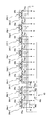
- FIG. 1 is an enlarged view showing an operation device and a pilot circuit portion of a hydraulic drive device for a hydraulic excavator according to a first embodiment of the present invention. It is a figure which shows the external appearance of the hydraulic shovel which is a construction machine. It is a figure which shows the relationship between the lever operation amount and operating pilot pressure (hydraulic signal) of the operating device for driving
- FIG. 2 shows the external appearance of the hydraulic excavator.
- a hydraulic excavator well known as a work machine includes an upper swing body 300, a lower traveling body 301, and a swing type front work machine 302.
- the front work machine 302 includes a boom 306, an arm 307, The bucket 308 is configured.
- the upper swing body 300 can swing the lower traveling body 301 by the rotation of the swing motor 7.
- a swing post 303 is attached to the front portion of the upper swing body 300, and a front work machine 302 is attached to the swing post 303 so as to be movable up and down.
- the swing post 303 can be rotated in the horizontal direction with respect to the upper swing body 300 by expansion and contraction of the swing cylinder 9 (see FIG. 1).
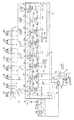
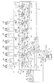
- FIG. 1A shows a hydraulic drive device for a hydraulic excavator according to the first embodiment of the present invention.
- the control valve 4 is connected to the supply oil passage 2a of the main pump 2, and has a plurality of valve sections 13, 14, 15, 16, 17 for controlling the direction and flow rate of the pressure oil supplied from the main pump 2 to each actuator. , 18, 19, 20 and a plurality of actuators 5, 6, 7, 8, 9, 10, 11, 12 to select the highest load pressure (hereinafter referred to as the maximum load pressure) PLmax and signal oil
- a plurality of shuttle valves 22 a, 22 b, 22 c, 22 d, 22 e, 22 f, and 22 g that are output to the passage 21 are connected to the supply oil passage 4 a that is connected to the supply oil passage 2 a of the main pump 2.
- a main relief valve 23 that limits the maximum discharge pressure (maximum pump pressure) and a pilot hydraulic pressure source 33 (described later), and signals the pressure in the supply oil passage 4a and the signal oil passage 21.
- the pressure is input as a pressure, and is connected to a differential pressure reducing valve 24 that outputs a differential pressure PLS between the discharge pressure (pump pressure) Pd of the main pump 2 and the maximum load pressure PLmax as an absolute pressure, and a supply oil passage 4a in the valve,
- the pressure of the oil passage 4a and the signal oil passage 21 is input as a signal pressure, and when the differential pressure PLS between the pump pressure Pd and the maximum load pressure PLmax exceeds a certain value set by the spring 25a, the discharge of the main pump 2
- An unload valve 25 is provided that returns a part of the flow rate to the tank T and keeps the differential pressure PLS below a predetermined value set by the spring 25a.
- the outlet sides of the unload valve 25 and the main relief valve 23 are connected to a tank oil
- the pressure compensation valves 27a to 27h are respectively connected to a plurality of parallel oil passages 41a to 41f branched from the in-valve supply oil passage 4a connected to the supply oil passage 2a of the main pump 2 on the upstream side of the flow control valves 26a to 26h. Has been placed.
- the flow control valves 26a to 26h control the direction and flow rate of the pressure oil supplied from the main pump 2 to the actuators 5 to 12, respectively.
- the pressure compensation valves 27a to 27h are differential pressures before and after the flow control valves 26a to 26h. To control each.
- the pressure compensating valves 27a to 27h have valve-opening side pressure receiving portions 28a, 28b, 28c, 28d, 28e, 28f, 28g, and 28h for setting a target differential pressure.
- the pressure receiving portions 28a to 28h include a differential pressure reducing valve 24.
- the target compensation differential pressure is set by the absolute pressure of the differential pressure PLS between the hydraulic pump pressure Pd and the maximum load pressure PLmax (hereinafter referred to as the absolute pressure PLS).
- the absolute pressure PLS the absolute pressure of the differential pressure PLS between the hydraulic pump pressure Pd and the maximum load pressure PLmax
- Control is performed so as to be equal to the differential pressure PLS with respect to the load pressure PLmax.
- the discharge flow rate of the main pump 2 is distributed according to the opening area ratio of the flow rate control valves 26a to 26h regardless of the load pressure of the actuators 5 to 12. Combined operability can be ensured.
- the differential pressure PLS decreases according to the degree of supply shortage, and the pressure compensation valves 27a to 27h control accordingly.
- the discharge flow rate of the main pump 2 can be distributed to ensure composite operability.
- the hydraulic drive device is connected to the supply oil passage 3 a of the pilot pump 3, and outputs the absolute pressure according to the discharge flow rate of the pilot pump 3, and the downstream side of the engine speed detection valve 30.
- a pilot hydraulic pressure source 33 having a pilot relief valve 32 that keeps the pressure of the pilot oil passage 31 constant, and a flow rate that is connected to the pilot oil passage 31 and uses the pressure of the pilot hydraulic pressure source 32 as an original pressure (pilot primary pressure).
- Operating pilot pressures (pilot secondary pressures) a, b, c, d, e, f, g, h, i, j, k, l, m, n, o, p for operating the control valves 26a to 26h
- Operating device 34a provided with remote control valves 34a-2, 34b-2, 34c-2, 34d-2, 34e-2, 34f-2, 34g-2, 34h-2 (see FIG. 1B) 34b, and includes 34c, 34d, 34e, 34f, 34g, and 34h.
- the engine speed detection valve 30 includes a throttle element (fixed throttle part) 30f provided in an oil path connecting the supply oil path 3a of the pilot pump 3 to the pilot oil path 31, and a flow rate connected in parallel to the throttle element 30f. It has a detection valve 30a and a differential pressure reducing valve 30b.
- the input side of the flow rate detection valve 30 a is connected to the supply oil passage 3 a of the pilot pump 3, and the output side of the flow rate detection valve 30 a is connected to the pilot oil passage 31.
- the flow rate detection valve 30a has a variable throttle portion 30c that increases the opening area as the passing flow rate increases, and the discharge oil of the pilot pump 3 passes through both the throttle element 30f and the variable throttle portion 30c of the flow rate detection valve 30a.
- a differential pressure increases and decreases as the passing flow rate increases in the throttle element 30f and the variable throttle portion 30c of the flow rate detection valve 30a, and the differential pressure reducing valve 30b outputs the differential pressure as the absolute pressure Pa.
- the discharge flow rate of the pilot pump 3 varies depending on the rotation speed of the engine 1
- the discharge flow rate of the pilot pump 3 can be detected by detecting the differential pressure across the throttle element 30f and the variable throttle portion 30c. The number of rotations can be detected.
- the variable throttle portion 30c increases the opening area as the passing flow rate increases (as the front-rear differential pressure increases), so that the degree of increase in the front-rear differential pressure becomes milder as the passing flow rate increases. It is configured as follows.
- the main pump 2 is a variable displacement hydraulic pump, and includes a pump control device 35 for controlling the tilt angle (capacity) thereof.
- the pump control device 35 includes a pump torque control unit 35A and an LS control unit 35B.
- the pump torque control unit 35A includes a torque control tilt actuator 35a, and the torque control tilt actuator 35a is configured so that the tilt angle (capacity) of the main pump 2 decreases as the discharge pressure of the main pump 2 increases.
- the swash plate (capacity variable member) 2s is driven, and the input torque of the main pump 2 is limited so as not to exceed the preset maximum torque. Thereby, the horsepower consumption of the main pump 2 is limited, and the stop (engine stall) of the engine 1 due to overload is prevented.
- the LS control unit 35B includes an LS control valve 35b and an LS control tilt actuator 35c.
- the LS control valve 35b has pressure receiving portions 35d and 35e facing each other, and the pressure receiving portion 35d receives the absolute pressure Pa generated by the differential pressure reducing valve 30b of the engine speed detection valve 30 via the oil passage 40.
- the absolute pressure PLS (the differential pressure PLS between the discharge pressure Pd of the main pump 2 and the maximum load pressure PLmax) generated by the differential pressure reducing valve 24 in the pressure receiving portion 35e is guided as a target differential pressure (target LS differential pressure). Guided as feedback differential pressure.
- the absolute pressure PLS becomes higher than the absolute pressure Pa (PLS> Pa)
- the LS control valve 35b guides the pressure of the pilot hydraulic source 33 to the LS control tilt actuator 35c, and the absolute pressure PLS becomes lower than the absolute pressure Pa.
- the LS control tilt actuator 35c is communicated with the tank T.
- the LS control tilt actuator 35c drives the swash plate 2s of the main pump 2 so that the tilt angle of the main pump 2 decreases when the pressure of the pilot hydraulic power source 33 is guided.
- the swash plate 2s of the main pump 2 is driven so as to increase the tilt angle.
- the tilt angle (capacity) of the main pump 2 is controlled so that the discharge pressure Pd of the main pump 2 becomes higher than the maximum load pressure PLmax by the absolute pressure Pa (target differential pressure).
- the set pressure of the spring 25a of the unload valve 25 is the absolute pressure Pa (target differential pressure for load sensing control) generated by the differential pressure reducing valve 30b of the engine speed detecting valve 30 when the engine 1 is at the rated maximum speed. ) Is set to be slightly higher.
- FIG. 1B is an enlarged view of the operation devices 34a, 34b, 34c, 34d, 34e, 34f, 34g, and 34h and their pilot circuit portions.
- the operating device 34a has an operating lever 34a-1 and a remote control valve 34a-2, and the remote control valve 34a-2 includes a pair of pressure reducing valves PVa and PVb.
- the pressure reducing valve PVa of the remote control valve 34a-2 is activated to generate an operation pilot pressure a having a magnitude corresponding to the operation amount of the operation lever 34a-1
- the operation lever 34a When -1 is operated in the left direction in the figure, the pressure reducing valve PVb of the remote control valve 34a-2 is activated to generate an operating pilot pressure b having a magnitude corresponding to the operating amount of the operating lever 34a-1.
- the operating pilot pressures d, f, h, j, l having magnitudes corresponding to the operating amounts of the levers 34b-1, 34c-1, 34d-1, 34e-1, 34f-1, 34g-1, 34h-1 n and p are generated.
- the switching valves 100f, 100g, and 100h each have two positions, a fully open communication position and a throttle position that reduces the opening area.
- the fully open position on the left side of the drawing is illustrated.
- the throttle position on the right side of the figure is switched.
- the switching valves 100f, 100g, and 100h are respectively switched to the throttle positions, thereby reducing the passage areas of the parallel oil passages 41f, 41g, and 41h that are the oil passage portions on the upstream side of the pressure compensation valves 27f, 27g, and 27h. .
- the hydraulic drive device further includes an operation detection device 43 that detects the operation of the travel operation devices 34a and 34b.
- the operation detection device 43 includes shuttle valves 48a, 48b, and 48c that detect an operation pilot pressure (traveling operation pilot pressure) generated by the traveling operation devices 34a and 34b and output the detected operation pilot pressure as a hydraulic pressure signal. (See FIG. 1B).
- the switching valves 100f, 100g, and 100h are hydraulic switching valves that are switched by the hydraulic signal (operating pilot pressure for traveling), and the hydraulic signals are guided to the pressure receiving portions 101f, 101g, and 101h of the switching valves 100f, 100g, and 100h. .
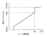
- FIG. 3A is a diagram showing the relationship between the lever operation amount of the operation devices 34a and 34b and the operation pilot pressure (hydraulic signal), and FIG. 3B shows the operation pilot pressure and the flow control valve 26a. It is a figure which shows the relationship between the opening area of meter-in and meter-out of 26b, and FIG. 3C is a figure which shows the relationship between the operation pilot pressure and the opening area of switching valve 100f, 100g, 100h.
- the operation pilot pressure increases from the minimum pressure Ppmin to the maximum pressure Ppmax (FIG. 3A), and the meter-in and meter-out opening areas of the flow control valves 26a and 26b increase as the operation pilot pressure increases. It increases from zero to a maximum Amax (FIG. 3B).
- Xa in FIG. 3A is a switching lever operation amount of the switching valves 100f, 100g, and 100h
- Ppa and Aa-in in FIGS. 3A to 3C are an operation pilot pressure and a meter-in opening area corresponding to the switching lever operation amount Xa
- A100-max is an opening area when the switching valves 100f, 100g, and 100h are in the communication position
- A100-lim is an opening area when the switching valves 100f, 100g, and 100h are in the throttle position.
- the travel operation pilot pressure is not generated, so that the switching valves 100f, 100g, and 100h are in the communication positions on the left side in the drawing. .
- the opening areas of the switching valves 100f, 100g, and 100h are A100-max.
- the oil discharged from the main pump 2 is supplied to the supply oil passages 2a and 4a, and the pressure in the supply oil passages 2a and 4a increases.
- the supply oil passage 4a is provided with an unload valve 25.
- the pressure in the supply oil passage 2a becomes higher than the maximum load pressure PLmax (in this case, the tank pressure) by more than the set pressure of the spring 25a.
- the pressure oil in the supply oil passage 2a is returned to the tank in an open state, and the increase in the pressure in the supply oil passage 2a is restricted. Thereby, the discharge pressure of the main pump 2 is controlled to the minimum pressure Pmin.
- the differential pressure reducing valve 24 outputs a differential pressure PLS between the discharge pressure Pd of the main pump 2 and the maximum load pressure PLmax (in this case, tank pressure) as an absolute pressure.
- the output pressure of the engine speed detection valve 30 and the output pressure of the differential pressure reducing valve 24 are guided to the LS control valve 35b of the LS control unit 35B of the main pump 2, and the discharge pressure of the main pump 2 increases.
- the LS control valve 35b is switched to the right position in the figure, and the pressure of the pilot hydraulic power source 33 is applied to the LS control tilt actuator 35c. It is guided and controlled so that the tilt angle of the main pump 2 becomes small.
- the main pump 2 is provided with a stopper (not shown) that defines the minimum tilt angle, the main pump 2 is held at the minimum tilt angle qmin defined by the stopper, and the minimum flow rate is maintained. Qmin is discharged.
- the load pressure of the boom cylinder 10 is detected as the maximum load pressure by the shuttle valves 22a to 22g and transmitted to the differential pressure reducing valve 24 and the unload valve 25.
- the flow control valves 26f and 26g are switched.
- the pressure oil is supplied to the boom cylinder 10 and the arm cylinder 11, and the boom cylinder 10 and the arm cylinder 11 are driven.
- the higher pressure of the load pressures of the boom cylinder 10 and the arm cylinder 11 is detected as the maximum load pressure PLmax by the shuttle valves 22a to 22g and transmitted to the differential pressure reducing valve 24 and the unloading valve 25.
- the output pressure of the engine speed detection valve 30 and the output pressure of the differential pressure reducing valve 24 are guided to the LS control valve 35b of the LS control unit 35B of the main pump 2, and the boom cylinder 10 is driven independently.
- the discharge pressure of the main pump 2 pressure in the supply oil passages 2a and 4a
- the output pressure (target differential pressure) of the engine speed detection valve 30 So-called load sensing control is performed in which the flow rate required by the flow rate control valves 26f and 26g is supplied to the boom cylinder 10 and the arm cylinder 11.
- the output pressure of the differential pressure reducing valve 24 is guided to the pressure compensating valves 27a to 27h as the target compensating differential pressure, and the pressure compensating valves 27f and 27g use the differential pressure before and after the flow control valves 26f and 26g to the main pump 2. Control is made to be equal to the differential pressure between the discharge pressure and the maximum load pressure PLmax. As a result, pressure oil is supplied to the boom cylinder 10 and the arm cylinder 11 at a ratio corresponding to the opening area of the meter-in throttle portions of the flow control valves 26f and 26g regardless of the load pressure of the boom cylinder 10 and the arm cylinder 11. Can do.
- the pressure compensation valves 27a to 27h are configured not to be fully closed at the stroke end in the direction of decreasing the opening area (left direction in the drawing), the other is operated during the operation of one of the boom cylinder 10 and the arm cylinder 11. Even if saturation occurs due to the combined operation, and the pressure compensation valve on the low load side moves greatly in the direction of decreasing the opening area, the pressure compensation valve on the low load pressure side is prevented from closing and the pressure oil is completely shut off Therefore, it is possible to prevent the actuator on the low load pressure side from being decelerated and stopped.
- the flow control valve 26g is switched and the arm cylinder 11 is switched. Also, pressure oil is supplied to drive the arm cylinder 11.
- the pressure compensation valve is a type of pressure compensation valve that does not fully close at the stroke end in the direction of decreasing the opening area
- another driven member for example, boom, arm, bucket
- the pressure compensation valve of low-load actuators such as boom cylinders, arm cylinders, and bucket cylinders, which have a lower load pressure than the traveling motor, will open even when the stroke end is reached. Therefore, all the discharge flow rate of the hydraulic pump flows through the low-load actuator, and traveling may be decelerated and stopped.
- the switching valves 100f and 100g are operated.
- 100h are switched to the throttle position on the right side of the drawing, and the passage areas of the parallel oil passages 41f, 41g, 41h, which are the oil passage portions upstream of the pressure compensation valves 27f, 27g, 27h, are reduced.
- the switching lever operation amount Xa of the switching valves 100f, 100g, and 100h is set as a value near the maximum operation amount Full, the lever operation amount in the low-speed traveling combined operation on the flat ground. Is less than Xa, and when the operating levers 34a-1, 34b-1 of the operating devices 34a, 34b for traveling are operated, the switching valves 100f, 100g, 100h are not switched to the throttle position, and the boom cylinder 10, the arm cylinder 11 The pressure oil flow rate supplied to the bucket cylinder 12 is not suppressed. As a result, the movement of the front work machine 302 is delayed, and workability is prevented from being lowered.
- the switching lever operation amount Xa of the switching valves 100f, 100g, and 100h is set as a value near the maximum operation amount Full, the movement of the front work machine 302 is not slow in the low-speed traveling combined operation on a flat ground, and the workability is improved. A decrease can be prevented.
- the switching valves 100f, 100g, and 100h are arranged in the parallel oil passages 41f, 41g, and 41h, when the operation levers 34a-1 and 34b-1 of the travel operation devices 34a and 34b are operated, the parallel oil passages 41f, Since the flow rate of pressure oil supplied only to the actuators corresponding to 41g and 41h (boom cylinder 10, arm cylinder 11, bucket cylinder 12) is suppressed, and the flow rate of pressure oil supplied to other actuators is not suppressed, The combined operation of driving the travel motors 5 and 6 and the other actuators can prevent a decrease in operability due to a decrease in the speed of the other actuators.
- the hydraulic drive device in the parallel oil passages 41f, 41g, 41h in which the pressure compensating valve 27f for the boom, the pressure compensating valve 27g for the arm, and the pressure compensating valve 27h for the bucket are arranged.
- the switching valves 100f, 100g, and 100h are arranged, the hydraulic drive device according to the present embodiment is an oil passage portion of the supply oil passage 4a connected to the supply oil passage 2a of the main pump 2, and is used for the boom.
- a valve 100 is arranged.
- the switching valve 100 like the switching valves 100f, 100g, and 100h, has two positions, a fully open communication position and a throttle position with a reduced opening area, and when the travel operation devices 34a and 34b are not operated.
- a hydraulic signal operating pilot pressure for traveling
- the switching valve 100 is switched to the throttle position, the passage area of the oil passage portion 42 is reduced, and the passage flow rates of the flow control valves 26f, 26g, and 26h are limited.
- the flow rate of the pressure oil supplied to the plurality of actuators by one switching valve 100 is suppressed, and the above-described effect can be obtained. Therefore, the number of components can be reduced and the effect can be obtained at a lower cost. be able to.
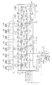
- FIG. 5 shows a hydraulic drive device for a hydraulic excavator according to a third embodiment of the present invention.
- the same components as those shown in FIG. The present embodiment is different from the first embodiment in the switching method of the switching valve provided in the oil passage portion on the upstream side of the pressure compensation valve.
- the hydraulic drive apparatus in the present embodiment includes electromagnetic switching valves 46f, 46g, 46h and a controller 71 instead of the hydraulic switching valves 100f, 100g, 100h in the first embodiment, and an operation detection device.
- a pressure for detecting an operation pilot pressure generated by the remote control valves 34a and 34b of the travel operation device among a plurality of operation devices and outputting an electric signal A sensor 72 is provided.
- the electrical signal of the pressure sensor 72 is input to the controller 71, and the controller 71 calculates an operation pilot pressure from the electrical signal.
- the operation pilot pressure exceeds Ppa (see FIG. 3A)
- the drive signal is transmitted to the electromagnetic switching valves 46f and 46g. , 46h.
- the electromagnetic switching valves 46f, 46g, 46h are in the communication position on the left side of the figure when the operating devices (specific operating devices) 34a, 34b for driving are not operated and no drive signal is output from the controller 71, When the operation devices 34a and 34b are operated and a drive signal is output from the controller 71, the control device switches to the aperture position on the right side of the figure.
- the electromagnetic switching valves 46f, 46g, and 46h are switched to the throttle positions to reduce the passage areas of the parallel oil passages 41f, 41g, and 41h, and the flow rates of the flow control valves 26f, g, and h are limited.
- the switching valves 100f, 100g, and 100h in FIG. 1 are replaced with electromagnetic switching valves.
- the switching valve 100 in FIG. 4 is replaced with an electromagnetic switching valve, and the same pressure as in this embodiment is used. It is also possible to provide a sensor and a controller so that the electromagnetic switching valve is switched by an electrical signal from the controller.
- FIG. 6 shows a hydraulic drive device for a hydraulic excavator according to a fourth embodiment of the present invention.
- the configuration for guiding the traveling pilot pressure to the switching valves 100f, 100g, and 100h is different from that of the first embodiment.
- the hydraulic drive device further includes a manual selection device 81 that can be switched between the first position and the second position.
- the manual selection device 81 is, for example, a switch that outputs an electrical signal corresponding to the switching position.
- the hydraulic pressure signal detected by the operation detection device 43 is disposed in the oil passage 48 that guides the hydraulic pressure signals detected by the operation detection device 43 to the pressure receiving portions 101f, 101g, and 101h of the switching valves 100f, 100g, and 100h.
- an electromagnetic switching valve 83 that operates based on the electrical signal from is provided.
- the electromagnetic switching valve 83 When the manual selection device 81 is in the first position and no electrical signal is output, the electromagnetic switching valve 83 is in the first position on the lower side in the figure, and in this first position, the hydraulic signal detected by the operation detection device 43. Can be guided to the pressure receiving portions 101f, 101g, 101h of the switching valves 100f, 100g, 100h, the manual selection device 81 is switched to the second position, and an electric signal is output to the solenoid 83a of the electromagnetic switching valve 83. To the second position on the upper side of the figure so that the hydraulic signal detected by the operation detection device 43 is not guided to the pressure receiving portions 101f, 101g, 101h of the switching valves 100f, 100g, 100h.
- the manual selection device 81 when the manual selection device 81 is switched to the second position, the supply of pressure oil by the switching valves 100f, 100g, 100h when the operation devices (specific operation devices) 34a, 34b for traveling are operated is suppressed.
- the function becomes invalid, and even when the traveling combined operation is performed, the pressure oil is not suppressed for the boom cylinder 10, the arm cylinder 11, and the bucket cylinder 12, and the conventional operation becomes possible.
- FIG. 7 shows a hydraulic drive device for a hydraulic excavator according to a fifth embodiment of the present invention.
- the switching valve disposed in the oil passage portion on the upstream side of the pressure compensation valve supplies not only the boom cylinder 10, the arm cylinder 11, and the bucket cylinder 12 but also the blade cylinder 8 by a traveling combined operation.
- the flow rate to be controlled can be suppressed.
- the switching valve 100d has two positions, that is, a fully open communication position and a throttle position that reduces the opening area, and when the traveling operation devices 34a and 34b are not operated.
- the hydraulic signal traveling operation pilot pressure
- the passage area of the parallel oil passage 41d decreases, and the passage flow rate of the flow control valve 26d is limited.
- the pressure compensating valve is a type of pressure compensating valve that does not fully close at the stroke end in the direction of decreasing the opening area. Since the pressure oil flows, the running is decelerated and a shock is produced sensibly and the operation feeling is impaired.
- the flow rate of the pressure oil supplied to the blade cylinder 8 is the same as when the operation lever of any one of the operation devices of the boom, arm, and bucket is operated for the front operation during traveling. Since it is suppressed by the switching valve 100d, a necessary amount of pressure oil to the traveling motors 5 and 6 is ensured, the traveling deceleration is prevented, and the operation feeling can be improved.
- FIG. 8 shows a hydraulic drive device for a hydraulic excavator according to the fifth embodiment of the present invention.
- the same components as those shown in FIG. by changing the arrangement position of the switching valve in the second embodiment shown in FIG. 4, not only the boom cylinder 10, the arm cylinder 11 and the bucket cylinder 12, but also all the actuators 7 other than traveling The flow rate supplied by the traveling combined operation to ⁇ 12 can be suppressed.
- the travel operation pilot pressure is generated so that the switching valve 100A is switched to the throttle position on the lower side in the figure.
- the passage flow rate of the flow control valves 26d to 26h is limited, the pressure oil supplied to all the actuators 7 to 12 of the actuators other than the traveling is suppressed. Therefore, the necessary amount of pressure oil to the travel motors 5 and 6 in the travel combined operation is secured for all the actuators 7 to 12 other than the travel, so that the travel is prevented from being stopped and good composite operability is achieved. Obtainable.
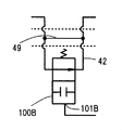
- FIG. 9A is another example of the switching valve disposed in the parallel oil passage 41f and the like
- FIG. 9B is a switching disposed in the oil passage portion 42 of the supply oil passage 4a connected to the supply oil passage 2a of the main pump 2.
- the bypass oil passage 48 or 49 is provided in the oil passage portion 42 of the parallel oil passage 41f or the supply oil passage 4a, and the passage area of the bypass oil passage 48 or 49 is set to the parallel oil passage 41f or the supply oil passage.
- 4a is made smaller than the passage area of the oil passage portion 42, and the bypass oil passage 48 or 49 is made to have the same throttle effect as when the switching valve 100f is in the throttle position.
- the switching valve 101fB or 100B has two positions, a fully open communication position and a fully closed close position, and is in a fully open communication position when the travel operation devices 34a and 34b are not operated.
- the operation devices 34a and 34b are operated, the operation devices 34a and 34b are switched to the closed position.
- the switching valve 101fB or 100B is switched to the closed position, the upstream and downstream portions of the switching valve 101fB or 100B of the parallel oil passage 41f or the oil passage portion 42 communicate with only the bypass oil passage 48 or 49 having a throttling effect.
- the switching valve 101fB or 100B can reduce the passage area of the parallel oil passage 41f or the oil passage portion 42 of the supply oil passage 4a when a specific operation device is operated, and the switching valve 100f or the like The same effect as when the switching valve 100 or the like is used can be obtained.
- the specific actuator is a travel motor
- a hydraulic drive apparatus including a pressure compensation valve that does not fully close at the stroke end in the opening area decreasing direction, If saturation occurs due to a compound operation that makes the load pressure difference particularly large, the actuator may be stopped because the majority of the discharge flow rate of the main pump is taken away by the actuator on the low load pressure side
- a reserve actuator provided in an attachment such as a crusher often has a high load pressure.
- the construction machine is a hydraulic excavator
- the present invention is applied to construction machines other than the hydraulic excavator (for example, a hydraulic crane, a wheeled excavator, etc.) to obtain the same effect. Can do.
Abstract
Description
<油圧ショベル>
図2に油圧ショベルの外観を示す。
<第1の実施の形態>
図1Aに本発明の第1の実施の形態に係わる油圧ショベルの油圧駆動装置を示す。
まず、本実施の形態に係わる油圧駆動装置の基本構成を説明する。
次に、本実施の形態に係わる油圧駆動装置の特徴的構成を説明する。
まず、本実施の形態の油圧駆動装置の基本構成の動作を説明する。
全ての操作装置34a~34hの操作レバー34a-1~34h-1が中立位置にある場合、全ての流量制御弁26a~26hは中立位置にあり、アクチュエータ5~12に圧油は供給されない。また、流量制御弁26a~26hが中立位置にあるときは、シャトル弁22a~22gにより検出される最高負荷圧PLmaxはタンク圧となる。
任意の被駆動部材、例えばブーム用の操作装置34fの操作レバー34f-1を操作した場合は、ブーム用の流量制御弁26fが切り換わり、ブームシリンダ10に圧油が供給され、ブームシリンダ10が駆動される。
以上の動作はエンジン1が最高定格回転数にあるときのものである。エンジン1の回転数を低速に下げた場合は、エンジン回転数検出弁30の出力圧がそれに応じて低下するため、LS制御部35BのLS制御弁35bの目標差圧も同様に低下する。また、ロードセンシング制御の結果、圧力補償弁27a~27hの目標補償差圧も同様に低下する。これによりエンジン回転数の低下に合わせてメインポンプ2の吐出流量と流量制御弁26a~26hの要求流量が減少し、アクチュエータ5~12の駆動速度が速くなりすぎることがなく、エンジン回転数を下げた場合の微操作性を向上することができる。
~特徴的構成の動作~
次に、本実施の形態の油圧駆動装置の特徴的構成の動作を説明する。
以上のように本実施の形態によれば、2つのアクチュエータの負荷圧の差が大きい複合操作でサチュレーションが生じた場合に、低負荷圧側の圧力補償弁の閉じ切りを防止して低負荷圧側のアクチュエータの減速、停止を防止するとともに、特定のアクチュエータである走行モータ5,6の駆動を含む走行複合操作において、他のアクチュエータであるブームシリンダ10、アームシリンダ11、バケットシリンダ12への圧油の流入を抑制し、走行モータ5,6に必要量の圧油を確保して走行の減速、停止を防止し、走行複合操作性を向上することができる。
図4に本発明の第2の実施の形態に係わる油圧ショベルの油圧駆動装置を示す。図中,図1に示した部材と同等のものには同じ符号を付し、説明を省略する。本実施の形態は、ブーム用、アーム用、バケット用の圧力補償弁27f,27g,27hの上流側の油路部分に配置した切換弁の構成が第1の実施の形態と異なっている。
図5に本発明の第3の実施の形態に係わる油圧ショベルの油圧駆動装置を示す。図中、図1に示した部材と同等のものには同じ符号を付し、説明を省略する。本実施の形態は、圧力補償弁の上流側の油路部分に設けた切換弁の切り換え方式が第1の実施の形態と異なっている。
図6に本発明の第4の実施の形態に係わる油圧ショベルの油圧駆動装置を示す。図中、図1に示した部材と同等のものには同じ符号を付し、説明を省略する。本実施の形態は、走行パイロット圧を切換弁100f,100g,100hに導く構成を第1の実施の形態と異ならせたものである。
図7に本発明の第5の実施の形態に係わる油圧ショベルの油圧駆動装置を示す。図中、図1に示した部材と同等のものには同じ符号を付し、説明を省略する。本実施の形態は、圧力補償弁の上流側の油路部分に配置される切換弁により、ブームシリンダ10、アームシリンダ11、バケットシリンダ12だけでなくブレードシリンダ8に対しても走行複合操作で供給される流量を抑制できるようにしたものである。
図8に本発明の第5の実施の形態に係わる油圧ショベルの油圧駆動装置を示す。図中、図1に示した部材と同等のものには同じ符号を付し、説明を省略する。本実施の形態は、図4に示した第2の実施の形態における切換弁の配置位置を変えることで、ブームシリンダ10、アームシリンダ11、バケットシリンダ12だけでなく、走行以外の全てのアクチュエータ7~12に対して走行複合操作で供給される流量を抑制できるようにしたものである。
以上の実施の形態は本発明の精神の範囲内で種々の変更が可能である。
2 油圧ポンプ(メインポンプ)
2a 供給油路
3 パイロットポンプ
3a 供給油路
4 コントロールバルブ
4a バルブ内供給油路
5~12 アクチュエータ
5,6 走行モータ(特定のアクチュエータ)
7 旋回モータ
8 ブレードシリンダ
9 スイングシリンダ
10 ブームシリンダ
11 アームシリンダ
12 バケットシリンダ
13~20 バルブセクション
21 信号油路
22a~22g シャトル弁
23 メインリリーフ弁
24 差圧減圧弁
25 アンロード弁
25a バネ
26a~26h 流量制御弁
27a~27h 圧力補償弁
29 バルブ内タンク油路
30 エンジン回転数検出弁装置
30a 流量検出弁
30b 差圧減圧弁
30c 可変絞り部
30f 固定絞り部
31 パイロット油路
32 パイロットリリーフ弁
33 パイロット油圧源
34a~34h 操作装置
34a-1~34h-1 操作レバー
34a-2~34h-2 リモコン弁
35 ポンプ制御装置
35A ポンプトルク制御部
35B LS制御部
35a トルク制御傾転アクチュエータ
35b LS制御弁
35c LS制御傾転アクチュエータ
35d,35e 受圧部
41a~41h 並列油路
42,42A 油路部分
43,43A 操作検出装置
46f,46g,46h 電磁切換弁
48 バイパス油路
49 バイパス油路
71 コントローラ
72 圧力センサ
81 手動選択装置
83 電磁切換弁
100f,100g,100h 切換弁
101f,101g,101h 受圧部
100 切換弁
101 受圧部
100d 切換弁
101d 受圧部
100A 切換弁
101A 受圧部
100fB 切換弁
101fB 受圧部
100B 切換弁
101B 受圧部
300 上部旋回体
301 下部走行体
302 フロント作業機
303 スイングポスト
304 中央フレーム
305 ブレード
306 ブーム
307 アーム
308 バケット
310,311 履帯
Claims (7)
- 可変容量型の油圧ポンプと、
この油圧ポンプから吐出された圧油により駆動される複数のアクチュエータと、
前記油圧ポンプから前記複数のアクチュエータに供給される圧油の流量を制御する複数の流量制御弁と、
前記複数のアクチュエータに対応して設けられ、前記複数の流量制御弁を駆動するための操作パイロット圧を生成するリモコン弁を備えた複数の操作装置と、
前記複数の流量制御弁の前後差圧をそれぞれ制御する複数の圧力補償弁と、
前記油圧ポンプの吐出圧が前記複数のアクチュエータの最高負荷圧より目標差圧だけ高くなるよう前記油圧ポンプの容量をロードセンシング制御するポンプ制御装置とを備え、
前記複数の圧力補償弁は、開口面積減少方向のストロークエンドにおいて全閉しないタイプの圧力補償弁である建設機械の油圧駆動装置において、
前記複数のアクチュエータは、他のアクチュエータと同時に駆動される複合操作において高負荷圧側となる特定のアクチュエータを含み、
前記他のアクチュエータの圧力補償弁の上流側及び下流側のいずれかの油路部分に、前記複数の操作装置のうち前記特定のアクチュエータに対応する特定の操作装置が操作されたときに前記油路部分の通路面積を減少させる切換弁を配置したことを特徴とする建設機械の油圧駆動装置。 - 請求項1記載の建設機械の油圧駆動装置において、
前記複数の圧力補償弁は、前記油圧ポンプに接続された供給油路から分岐する複数の並列油路にそれぞれ配置されており、
前記油路部分は、前記複数の並列油路のうち前記他のアクチュエータの圧力補償弁が配置される並列油路であることを特徴とする建設機械の油圧駆動装置。 - 請求項1記載の建設機械の油圧駆動装置において、
前記複数の圧力補償弁は、前記油圧ポンプに接続された供給油路から分岐する複数の並列油路にそれぞれ配置されており、
前記油路部分は、前記供給油路の一部分であって、前記他のアクチュエータの圧力補償弁が配置される並列油路の分岐位置より上流側の油路部分であることを特徴とする建設機械の油圧駆動装置。 - 請求項1記載の建設機械の油圧駆動装置において、
前記特定の操作装置のリモコン弁が生成する操作パイロット圧を検出して油圧信号として出力するシャトル弁を更に備え、
前記切換弁は前記油圧信号により切り換えられる油圧切換弁であることを特徴とする建設機械の油圧駆動装置。 - 請求項1記載の建設機械の油圧駆動装置において、
前記特定の操作装置のリモコン弁が生成する操作パイロット圧を検出して電気信号を出力する圧力センサを更に備え、
前記切換弁は前記電気信号に基づいて動作する電磁切換弁であることを特徴とする建設機械の油圧駆動装置。 - 請求項1記載の建設機械の油圧駆動装置において、
第1位置と第2位置とに切り換え可能な手動選択装置と、
前記手動選択装置が前記第1位置にあるときは、前記特定の操作装置が操作されたときの前記切換弁の前記油路部分の通路面積を減少させる機能を有効とし、前記手動選択装置が前記第2位置に切り換えられると、前記特定の操作装置が操作されたときの前記切換弁の前記油路部分の通路面積を減少させる機能を無効とする制御装置とを更に備えることを特徴とする建設機械の油圧駆動装置。 - 請求項1記載の建設機械の油圧駆動装置において、
前記特定のアクチュエータは、建設機械の走行体を駆動する走行モータであり、
前記他のアクチュエータは、建設機械のフロント作業機を動かす複数の油圧シリンダのいずれかか、ブレードを動かすブレードシリンダであることを特徴とする建設機械の油圧駆動装置。
Priority Applications (5)
| Application Number | Priority Date | Filing Date | Title |
|---|---|---|---|
| US14/423,868 US9828746B2 (en) | 2012-10-17 | 2013-10-08 | Hydraulic driving system for construction machine |
| JP2014542065A JP5984164B2 (ja) | 2012-10-17 | 2013-10-08 | 建設機械の油圧駆動装置 |
| KR1020157005180A KR101719676B1 (ko) | 2012-10-17 | 2013-10-08 | 건설 기계의 유압 구동 장치 |
| EP13847113.1A EP2910797B1 (en) | 2012-10-17 | 2013-10-08 | Hydraulic drive device for construction machinery |
| CN201380044896.7A CN104603468B (zh) | 2012-10-17 | 2013-10-08 | 工程机械的液压驱动装置 |
Applications Claiming Priority (2)
| Application Number | Priority Date | Filing Date | Title |
|---|---|---|---|
| JP2012-230071 | 2012-10-17 | ||
| JP2012230071 | 2012-10-17 |
Publications (1)
| Publication Number | Publication Date |
|---|---|
| WO2014061507A1 true WO2014061507A1 (ja) | 2014-04-24 |
Family
ID=50488076
Family Applications (1)
| Application Number | Title | Priority Date | Filing Date |
|---|---|---|---|
| PCT/JP2013/077364 WO2014061507A1 (ja) | 2012-10-17 | 2013-10-08 | 建設機械の油圧駆動装置 |
Country Status (6)
| Country | Link |
|---|---|
| US (1) | US9828746B2 (ja) |
| EP (1) | EP2910797B1 (ja) |
| JP (1) | JP5984164B2 (ja) |
| KR (1) | KR101719676B1 (ja) |
| CN (1) | CN104603468B (ja) |
| WO (1) | WO2014061507A1 (ja) |
Cited By (3)
| Publication number | Priority date | Publication date | Assignee | Title |
|---|---|---|---|---|
| WO2015198868A1 (ja) * | 2014-06-23 | 2015-12-30 | 日立建機株式会社 | 建設機械の油圧駆動装置 |
| JP2018054010A (ja) * | 2016-09-28 | 2018-04-05 | 株式会社日立建機ティエラ | 建設機械の油圧駆動装置 |
| JP2021156355A (ja) * | 2020-03-26 | 2021-10-07 | 株式会社日立建機ティエラ | 建設機械の油圧駆動装置 |
Families Citing this family (13)
| Publication number | Priority date | Publication date | Assignee | Title |
|---|---|---|---|---|
| JP5878811B2 (ja) * | 2012-04-10 | 2016-03-08 | 日立建機株式会社 | 建設機械の油圧駆動装置 |
| FR3007154B1 (fr) * | 2013-06-12 | 2015-06-05 | Montabert Roger | Procede de commande de l’energie d’impact d’un piston de frappe d’un appareil a percussions |
| DE102015216737A1 (de) * | 2015-09-02 | 2017-03-02 | Robert Bosch Gmbh | Hydraulische Steuervorrichtung für zwei Pumpen und mehrere Aktuatoren |
| SE542526C2 (en) | 2015-10-19 | 2020-06-02 | Husqvarna Ab | Energy buffer arrangement and method for remote controlled demolition robot |
| SE539241C2 (en) * | 2015-10-19 | 2017-05-23 | Husqvarna Ab | Adaptive control of hydraulic tool on remote demolition robot |
| SE542525C2 (en) | 2015-10-19 | 2020-06-02 | Husqvarna Ab | Automatic tuning of valve for remote controlled demolition robot |
| JP6656913B2 (ja) * | 2015-12-24 | 2020-03-04 | 株式会社クボタ | 作業機の油圧システム |
| CN105545831B (zh) * | 2016-03-19 | 2017-05-31 | 青岛大学 | 一种装袋机双扒土机构节能联动控制系统 |
| JP6831648B2 (ja) * | 2016-06-20 | 2021-02-17 | 川崎重工業株式会社 | 液圧駆動システム |
| CN108506259B (zh) * | 2018-04-09 | 2022-02-11 | 徐州燕大传动与控制技术有限公司 | 一种阀后补偿的进出口独立控制的负荷传感式多路阀 |
| CN111364550A (zh) * | 2020-04-13 | 2020-07-03 | 三一重机有限公司 | 分体式液压多路换向阀系统和挖掘机 |
| CN114483677B (zh) * | 2021-12-27 | 2024-01-23 | 湖南中联重科应急装备有限公司 | 伸缩马达液压系统和云梯消防车 |
| CN116447191B (zh) * | 2023-04-10 | 2024-01-16 | 重庆大学 | 一种双执行器阀口独立控制系统主动阻尼补偿抑振方法 |
Citations (7)
| Publication number | Priority date | Publication date | Assignee | Title |
|---|---|---|---|---|
| JPS646501A (en) * | 1987-06-30 | 1989-01-11 | Hitachi Construction Machinery | Control apparatus for load sensing hydraulic drive circuit |
| JPH0419406A (ja) * | 1990-04-05 | 1992-01-23 | Toshiba Mach Co Ltd | 油圧作業回路 |
| JPH0762694A (ja) * | 1993-08-30 | 1995-03-07 | Hitachi Constr Mach Co Ltd | 建設機械の油圧駆動装置 |
| JPH0776861A (ja) | 1993-09-06 | 1995-03-20 | Hitachi Constr Mach Co Ltd | 建設機械の油圧駆動装置 |
| JP2005226678A (ja) * | 2004-02-10 | 2005-08-25 | Hitachi Constr Mach Co Ltd | 油圧駆動装置 |
| JP2007024103A (ja) | 2005-07-13 | 2007-02-01 | Hitachi Constr Mach Co Ltd | 油圧駆動装置 |
| JP2010101095A (ja) * | 2008-10-24 | 2010-05-06 | Kobelco Contstruction Machinery Ltd | 作業機械の油圧制御装置 |
Family Cites Families (8)
| Publication number | Priority date | Publication date | Assignee | Title |
|---|---|---|---|---|
| IN171213B (ja) * | 1988-01-27 | 1992-08-15 | Hitachi Construction Machinery | |
| JPH04136507A (ja) * | 1990-09-28 | 1992-05-11 | Komatsu Ltd | 油圧回路 |
| CN1155866A (zh) * | 1994-06-21 | 1997-07-30 | 株式会社小松制作所 | 液压驱动型移动装置的移动控制回路 |
| US6318079B1 (en) * | 2000-08-08 | 2001-11-20 | Husco International, Inc. | Hydraulic control valve system with pressure compensated flow control |
| JP3816893B2 (ja) * | 2003-04-17 | 2006-08-30 | 日立建機株式会社 | 油圧駆動装置 |
| JP2009167618A (ja) * | 2008-01-11 | 2009-07-30 | Caterpillar Japan Ltd | 油圧ショベルの油圧回路 |
| JP2011196439A (ja) * | 2010-03-18 | 2011-10-06 | Yanmar Co Ltd | 旋回作業車の油圧回路 |
| JP5383591B2 (ja) * | 2010-05-24 | 2014-01-08 | 日立建機株式会社 | 建設機械の油圧駆動装置 |
-
2013
- 2013-10-08 JP JP2014542065A patent/JP5984164B2/ja active Active
- 2013-10-08 US US14/423,868 patent/US9828746B2/en active Active
- 2013-10-08 KR KR1020157005180A patent/KR101719676B1/ko active IP Right Grant
- 2013-10-08 CN CN201380044896.7A patent/CN104603468B/zh active Active
- 2013-10-08 EP EP13847113.1A patent/EP2910797B1/en active Active
- 2013-10-08 WO PCT/JP2013/077364 patent/WO2014061507A1/ja active Application Filing
Patent Citations (7)
| Publication number | Priority date | Publication date | Assignee | Title |
|---|---|---|---|---|
| JPS646501A (en) * | 1987-06-30 | 1989-01-11 | Hitachi Construction Machinery | Control apparatus for load sensing hydraulic drive circuit |
| JPH0419406A (ja) * | 1990-04-05 | 1992-01-23 | Toshiba Mach Co Ltd | 油圧作業回路 |
| JPH0762694A (ja) * | 1993-08-30 | 1995-03-07 | Hitachi Constr Mach Co Ltd | 建設機械の油圧駆動装置 |
| JPH0776861A (ja) | 1993-09-06 | 1995-03-20 | Hitachi Constr Mach Co Ltd | 建設機械の油圧駆動装置 |
| JP2005226678A (ja) * | 2004-02-10 | 2005-08-25 | Hitachi Constr Mach Co Ltd | 油圧駆動装置 |
| JP2007024103A (ja) | 2005-07-13 | 2007-02-01 | Hitachi Constr Mach Co Ltd | 油圧駆動装置 |
| JP2010101095A (ja) * | 2008-10-24 | 2010-05-06 | Kobelco Contstruction Machinery Ltd | 作業機械の油圧制御装置 |
Cited By (10)
| Publication number | Priority date | Publication date | Assignee | Title |
|---|---|---|---|---|
| WO2015198868A1 (ja) * | 2014-06-23 | 2015-12-30 | 日立建機株式会社 | 建設機械の油圧駆動装置 |
| JP2016008625A (ja) * | 2014-06-23 | 2016-01-18 | 日立建機株式会社 | 建設機械の油圧駆動装置 |
| CN106133333A (zh) * | 2014-06-23 | 2016-11-16 | 株式会社日立建机Tierra | 工程机械的液压驱动装置 |
| EP3159550A4 (en) * | 2014-06-23 | 2018-02-28 | Hitachi Construction Machinery Tierra Co., Ltd. | Hydraulic drive device of construction machine |
| CN106133333B (zh) * | 2014-06-23 | 2018-03-27 | 株式会社日立建机Tierra | 工程机械的液压驱动装置 |
| KR101876895B1 (ko) * | 2014-06-23 | 2018-07-10 | 가부시키가이샤 히다치 겡키 티에라 | 건설 기계의 유압 구동 장치 |
| US10100495B2 (en) | 2014-06-23 | 2018-10-16 | Hitachi Construction Machinery Tierra Co., Ltd. | Hydraulic driving system for construction machine |
| JP2018054010A (ja) * | 2016-09-28 | 2018-04-05 | 株式会社日立建機ティエラ | 建設機械の油圧駆動装置 |
| JP2021156355A (ja) * | 2020-03-26 | 2021-10-07 | 株式会社日立建機ティエラ | 建設機械の油圧駆動装置 |
| JP7319942B2 (ja) | 2020-03-26 | 2023-08-02 | 株式会社日立建機ティエラ | 建設機械の油圧駆動装置 |
Also Published As
| Publication number | Publication date |
|---|---|
| EP2910797A1 (en) | 2015-08-26 |
| US20150240455A1 (en) | 2015-08-27 |
| JPWO2014061507A1 (ja) | 2016-09-05 |
| KR20150038476A (ko) | 2015-04-08 |
| EP2910797A4 (en) | 2016-05-25 |
| CN104603468B (zh) | 2017-07-11 |
| CN104603468A (zh) | 2015-05-06 |
| KR101719676B1 (ko) | 2017-03-24 |
| JP5984164B2 (ja) | 2016-09-06 |
| US9828746B2 (en) | 2017-11-28 |
| EP2910797B1 (en) | 2018-12-12 |
Similar Documents
| Publication | Publication Date | Title |
|---|---|---|
| JP5984164B2 (ja) | 建設機械の油圧駆動装置 | |
| JP5878811B2 (ja) | 建設機械の油圧駆動装置 | |
| JP5687150B2 (ja) | 建設機械 | |
| EP1760326B1 (en) | Hydraulic controller for working machine | |
| JP5383591B2 (ja) | 建設機械の油圧駆動装置 | |
| JP5886976B2 (ja) | 作業機械 | |
| KR20120123069A (ko) | 유압 시스템의 펌프 제어 장치 | |
| WO2019220872A1 (ja) | 作業機械の油圧駆動装置 | |
| JP2014029180A (ja) | 作業機械の油圧制御装置 | |
| US20140283915A1 (en) | Hydraulic Control System Having Relief Flow Capture | |
| JP2012162917A (ja) | 油圧ショベルの油圧回路 | |
| JP2012112466A (ja) | 建設機械の油圧システム | |
| JP6615137B2 (ja) | 建設機械の油圧駆動装置 | |
| JP6591370B2 (ja) | 建設機械の油圧制御装置 | |
| JP2009179983A (ja) | 作業機械の油圧制御回路 | |
| JP7207060B2 (ja) | 作業機械の油圧駆動装置 | |
| JP2015143533A (ja) | 作業機の制御システム | |
| JP2009256904A (ja) | 作業機械の油圧制御回路 | |
| JP6564753B2 (ja) | 建設機械の油圧駆動装置 | |
| JP5602034B2 (ja) | ホイール式走行作業車の走行駆動回路装置 | |
| JP2010065733A (ja) | 作業機械の油圧制御回路 | |
| JP7268435B2 (ja) | 作業機械の油圧駆動装置 | |
| JP2012007656A (ja) | 作業機械の旋回用油圧制御装置 | |
| JP2010077750A (ja) | 作業機械の油圧制御回路 |
Legal Events
| Date | Code | Title | Description |
|---|---|---|---|
| 121 | Ep: the epo has been informed by wipo that ep was designated in this application |
Ref document number: 13847113 Country of ref document: EP Kind code of ref document: A1 |
|
| ENP | Entry into the national phase |
Ref document number: 2014542065 Country of ref document: JP Kind code of ref document: A |
|
| WWE | Wipo information: entry into national phase |
Ref document number: 14423868 Country of ref document: US |
|
| ENP | Entry into the national phase |
Ref document number: 20157005180 Country of ref document: KR Kind code of ref document: A |
|
| WWE | Wipo information: entry into national phase |
Ref document number: 2013847113 Country of ref document: EP |
|
| NENP | Non-entry into the national phase |
Ref country code: DE |