WO2014061441A1 - ガス制御弁およびこれに用いるディスク部品 - Google Patents
ガス制御弁およびこれに用いるディスク部品 Download PDFInfo
- Publication number
- WO2014061441A1 WO2014061441A1 PCT/JP2013/076671 JP2013076671W WO2014061441A1 WO 2014061441 A1 WO2014061441 A1 WO 2014061441A1 JP 2013076671 W JP2013076671 W JP 2013076671W WO 2014061441 A1 WO2014061441 A1 WO 2014061441A1
- Authority
- WO
- WIPO (PCT)
- Prior art keywords
- gas
- communication hole
- side communication
- minimum
- disk
- Prior art date
- Legal status (The legal status is an assumption and is not a legal conclusion. Google has not performed a legal analysis and makes no representation as to the accuracy of the status listed.)
- Ceased
Links
Images


Classifications
-
- F—MECHANICAL ENGINEERING; LIGHTING; HEATING; WEAPONS; BLASTING
- F23—COMBUSTION APPARATUS; COMBUSTION PROCESSES
- F23N—REGULATING OR CONTROLLING COMBUSTION
- F23N1/00—Regulating fuel supply
- F23N1/007—Regulating fuel supply using mechanical means
-
- F—MECHANICAL ENGINEERING; LIGHTING; HEATING; WEAPONS; BLASTING
- F16—ENGINEERING ELEMENTS AND UNITS; GENERAL MEASURES FOR PRODUCING AND MAINTAINING EFFECTIVE FUNCTIONING OF MACHINES OR INSTALLATIONS; THERMAL INSULATION IN GENERAL
- F16K—VALVES; TAPS; COCKS; ACTUATING-FLOATS; DEVICES FOR VENTING OR AERATING
- F16K11/00—Multiple-way valves, e.g. mixing valves; Pipe fittings incorporating such valves
- F16K11/02—Multiple-way valves, e.g. mixing valves; Pipe fittings incorporating such valves with all movable sealing faces moving as one unit
- F16K11/04—Multiple-way valves, e.g. mixing valves; Pipe fittings incorporating such valves with all movable sealing faces moving as one unit comprising only lift valves
- F16K11/056—Multiple-way valves, e.g. mixing valves; Pipe fittings incorporating such valves with all movable sealing faces moving as one unit comprising only lift valves with ball-shaped valve members
- F16K11/0565—Multiple-way valves, e.g. mixing valves; Pipe fittings incorporating such valves with all movable sealing faces moving as one unit comprising only lift valves with ball-shaped valve members moving in a combined straight line and rotating movement
-
- F—MECHANICAL ENGINEERING; LIGHTING; HEATING; WEAPONS; BLASTING
- F16—ENGINEERING ELEMENTS AND UNITS; GENERAL MEASURES FOR PRODUCING AND MAINTAINING EFFECTIVE FUNCTIONING OF MACHINES OR INSTALLATIONS; THERMAL INSULATION IN GENERAL
- F16K—VALVES; TAPS; COCKS; ACTUATING-FLOATS; DEVICES FOR VENTING OR AERATING
- F16K3/00—Gate valves or sliding valves, i.e. cut-off apparatus with closing members having a sliding movement along the seat for opening and closing
- F16K3/02—Gate valves or sliding valves, i.e. cut-off apparatus with closing members having a sliding movement along the seat for opening and closing with flat sealing faces; Packings therefor
- F16K3/04—Gate valves or sliding valves, i.e. cut-off apparatus with closing members having a sliding movement along the seat for opening and closing with flat sealing faces; Packings therefor with pivoted closure members
- F16K3/06—Gate valves or sliding valves, i.e. cut-off apparatus with closing members having a sliding movement along the seat for opening and closing with flat sealing faces; Packings therefor with pivoted closure members in the form of closure plates arranged between supply and discharge passages
- F16K3/08—Gate valves or sliding valves, i.e. cut-off apparatus with closing members having a sliding movement along the seat for opening and closing with flat sealing faces; Packings therefor with pivoted closure members in the form of closure plates arranged between supply and discharge passages with circular plates rotatable around their centres
- F16K3/085—Gate valves or sliding valves, i.e. cut-off apparatus with closing members having a sliding movement along the seat for opening and closing with flat sealing faces; Packings therefor with pivoted closure members in the form of closure plates arranged between supply and discharge passages with circular plates rotatable around their centres the axis of supply passage and the axis of discharge passage being coaxial and parallel to the axis of rotation of the plates
-
- F—MECHANICAL ENGINEERING; LIGHTING; HEATING; WEAPONS; BLASTING
- F23—COMBUSTION APPARATUS; COMBUSTION PROCESSES
- F23N—REGULATING OR CONTROLLING COMBUSTION
- F23N2235/00—Valves, nozzles or pumps
- F23N2235/12—Fuel valves
- F23N2235/14—Fuel valves electromagnetically operated
-
- F—MECHANICAL ENGINEERING; LIGHTING; HEATING; WEAPONS; BLASTING
- F23—COMBUSTION APPARATUS; COMBUSTION PROCESSES
- F23N—REGULATING OR CONTROLLING COMBUSTION
- F23N2235/00—Valves, nozzles or pumps
- F23N2235/12—Fuel valves
- F23N2235/16—Fuel valves variable flow or proportional valves
-
- F—MECHANICAL ENGINEERING; LIGHTING; HEATING; WEAPONS; BLASTING
- F23—COMBUSTION APPARATUS; COMBUSTION PROCESSES
- F23N—REGULATING OR CONTROLLING COMBUSTION
- F23N2235/00—Valves, nozzles or pumps
- F23N2235/12—Fuel valves
- F23N2235/24—Valve details
-
- F—MECHANICAL ENGINEERING; LIGHTING; HEATING; WEAPONS; BLASTING
- F23—COMBUSTION APPARATUS; COMBUSTION PROCESSES
- F23N—REGULATING OR CONTROLLING COMBUSTION
- F23N2237/00—Controlling
- F23N2237/08—Controlling two or more different types of fuel simultaneously
Definitions
- the present invention relates to a gas control valve for controlling the amount of fuel gas supplied to a gas burner of a gas appliance and a disk component used therefor.
- gas appliances are provided with a thermal power control device (gas control valve) that adjusts the thermal power of the gas burner by increasing or decreasing the amount of gas supplied to the gas burner.
- a thermal power control device gas control valve
- a fixed disk and a rotating disk that rotates in close contact with the fixed disk are provided, and a gas supply amount is controlled by making a hole provided in the fixed disk and a hole provided in the rotating disk face each other.
- gas control valves are known (for example, see Patent Documents 1 and 2).
- the minimum gas flow rate at which the flame of the gas burner does not disappear differs depending on the type of fuel gas (LP gas or city gas) having a different calorific value and specific gravity and the type of gas burner having different combustion capacity. For this reason, it is necessary to be able to set the minimum gas flow rate for each type of fuel gas to be used and each gas burner.
- the gas control valves described in Patent Documents 1 and 2 are also devised in this regard.
- a valve opening hole 81 is provided through the opening / closing plate 8 (rotary disk) so as to penetrate vertically.
- the gas passage plate 9 fixed disk
- the opening / closing plate 8 rotates, the valve opening hole 81 coincides with one of the gas passage holes 91. Then, the gas flows upward through the matched gas passage hole 91.
- the opening / closing plate 8 is rotated, the number and size of the gas passage holes 91 that coincide with the valve opening holes 81 change, so that the flow rate of the gas flowing upward increases or decreases.
- an orifice plate 93 is attached to the upper surface of the gas passage plate 9, and the amount of gas is adjusted according to the gas type, particularly when a gas having a flow rate corresponding to medium to low fire flows. Therefore, if the gas type is different, only the orifice plate 93 needs to be replaced.
- the fixed disk 5 has five holes 51 to 55 as first communication holes. Are continuously provided on the same circumference with different opening areas.
- one elliptical second communication hole 41 is formed in the rotating disk 4. The second communication hole 41 coincides with the holes 51 to 55 of the first communication hole when the rotary shaft 32 rotates by a predetermined angle, and allows the gas inlet 23 and the gas outlet 24 to communicate with each other through the internal passage 21. To do.
- a bypass passage 13 that connects the first hole 51 of the first communication hole and the gas passage 11 is provided in the main body 12, and the minimum gas flow is set.
- An orifice 14 for setting the flow rate is inserted in the bypass passage 13.
- gas appliances have different gas volume settings depending on the gas type and gas burner.
- the setting of the minimum heating power (minimum gas flow rate) is determined not by the size of the nozzle on the gas appliance side but by the size of the hole on the gas control valve side.
- the minimum gas flow rate Normally, since the minimum gas flow rate of 0.3 to 0.4 kW is controlled stably in a household stove, adjustment of the minimum gas flow rate is handled by a dedicated orifice as in Patent Documents 1 and 2.
- Patent Documents 1 and 2 there is a problem that many kinds of orifices require a lot of manufacturing costs and inventory costs because it is necessary to prepare many kinds of orifices as different dedicated parts for each gas type and gas burner.
- Patent Documents 1 and 2 in the configuration in which a plurality of holes having different sizes are provided on the fixed disk side and the hole on the rotating disk side is opposed to one of them, the gas flow rate is controlled.
- the firepower can be adjusted only by the number of stages according to the number.
- the present invention has been made to solve such problems, and an object of the present invention is to enable adjustment of the minimum gas flow rate without providing different dedicated parts for each gas type and gas burner. And Another object of the present invention is to enable continuous switching of the thermal power from the minimum thermal power to the maximum thermal power.
- fuel gas is allowed to flow through a fixed communication hole provided in a fixed disk and a rotary communication hole provided in a rotating disk that rotates in close contact with the fixed disk.
- the gas control valve configured to control the supply amount of the fuel gas to the gas burner
- one of the fixed side communication hole and the rotation side communication hole has a constant width and depth from a groove having a predetermined length.
- a minimum throttling section, an intermediate throttling section composed of a groove whose width or depth gradually changes, and an opening composed of a through hole, the minimum throttling section, the middle throttling section, and the opening Are provided continuously.
- the rotating disk rotates, Fuel gas supplied from the gas passage to the opening of the rotation side communication hole when a part of the minimum throttle section of the rotation side communication hole provided in the rotation disk and the fixed side communication hole provided in the fixed disk face each other Flows through the groove of the intermediate throttle section and the groove of the portion not opposed to the fixed communication hole of the minimum throttle section to the fixed communication hole.
- the minimum gas flow rate can be adjusted by controlling the position of the minimum throttle section that faces the fixed side communication hole in accordance with the gas type and gas burner.
- the minimum gas flow rate can be adjusted without providing different dedicated parts (dedicated orifices) for each gas type and gas burner.
- the minimum throttle section, the intermediate throttle section, and the opening are provided continuously, the minimum throttle section is opposed to the fixed communication hole, and the intermediate Continuously control the magnitude of the gas flow rate supplied to the gas burner through the intermediate gas flow rate with the throttle section facing the fixed communication hole and the maximum gas flow rate with the opening facing the fixed communication hole. Can do. Thereby, according to this invention, switching of a thermal power can be performed continuously from the minimum thermal power to the maximum thermal power.
- FIG. 3 is a cross-sectional view taken along the line AA of the gas control valve shown in FIG. 2, showing a configuration example of a fixed side communication hole and a rotation side communication hole according to this embodiment.
- FIG. 3 shows the example of adjustment of the thermal power by the gas control valve of this embodiment, and is a figure which shows the relationship between the opposing position of a fixed side communication hole and a rotation side communication hole, and a thermal power.
- FIG. 1 is a view showing a gas path of a gas appliance using a gas control valve according to the present embodiment.
- the gas control valve 100 of the present embodiment is applied to a gas appliance such as a gas stove, and increases or decreases the amount of gas supplied to the gas burner 300 via the nozzle 200 of the gas appliance. Then, the heating power of the gas burner 300 is adjusted.
- FIG. 2 is a cross-sectional view of the gas control valve 100 according to the present embodiment.
- the gas control valve 100 according to this embodiment includes a fixed-side communication hole 23 provided in the fixed disk 21 and a rotary-side communication provided in the rotating disk 22 that rotates in close contact with the fixed disk 21.
- the amount of fuel gas supplied to the gas burner 300 is controlled by flowing fuel gas through a hole (not shown in FIG. 2).
- the rotary disk 22 is urged upward in the figure by a spring 26 to form a contact surface 25 with the fixed disk 21.
- the fixed side communication hole 23 provided in the fixed disk 21 is a through hole having a certain opening area.
- the rotation side communication hole provided in the rotary disk 22 is configured to have a shape capable of controlling the gas flow rate to the fixed side communication hole 23 as the rotation disk 22 rotates (details will be described later).
- the rotating disk 22 corresponds to the disk component of the present invention
- the rotation side communication hole corresponds to the communication hole of the present invention
- the fixed side communication hole 23 of the fixed disk 21 corresponds to the other side communication hole.
- the rotating disk 22 is rotated by the motor 30, and the fuel is supplied to the gas burner 300 by flowing the gas with the appropriate position of the rotating side communication hole provided in the rotating disk 22 facing the fixed side communication hole 23.
- Control the gas supply That is, the flow rate of the fuel gas supplied to the gas burner 300 is controlled according to the position where the rotation side communication hole faces the fixed side communication hole 23.
- the power from the motor 30 is transmitted to the rotating disk 22 via the power transmission disk 27 connected to the motor rotating shaft 11, whereby the rotating disk 22 rotates in conjunction with the rotation of the motor 30. ing.
- the power transmission disk 27 includes a power transmission member (not shown) for transmitting the power from the motor 30 to the rotary disk 22, separately from the motor rotation shaft 11.
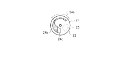
- FIG. 3 is a cross-sectional view taken along line AA of the gas control valve 100 shown in FIG. 2, and the stationary communication hole 23 of the stationary disk 21 and the rotational communication hole 24 (24a, 24b, 24a) of the rotating disk 22 according to the present embodiment.
- 24c) shows a configuration example.
- the fixed side communication hole 23 provided in the fixed disk 21 is configured by a through hole having a certain opening area.
- the rotation-side communication hole 24 included in the rotary disk 22 includes a minimum throttle section 24a composed of a groove having a constant width and depth and a groove having at least one of width and depth that gradually changes.
- the intermediate diaphragm section 24b and the opening 24c made of a through hole are provided, and the minimum diaphragm section 24a, the intermediate diaphragm section 24b, and the opening 24c are continuously provided.
- the rotary disk 22 is made of resin, for example.
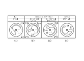
- FIG. 4 is a diagram showing an example of adjusting the thermal power by the gas control valve 100 of the present embodiment, and shows the relationship between the opposing positions of the fixed side communication hole 23 and the rotation side communication hole 24 and the thermal power.
- FIG. 4A shows a state in which the rotation side communication hole 24 is at the origin (a position where the rotation angle of the rotary disk 22 is 0 °). In this state, the fixed side communication hole 23 and the rotation side communication hole 24 are not opposed to each other, and no gas is supplied from the rotation side communication hole 24 to the fixed side communication hole 23 side.
- FIG. 4 (b) and 4 (c) show the state of the rotation side communication hole 24 in the case where the minimum gas flow rate (minimum heating power) is set such that the flame of the gas burner 300 does not disappear.
- the rotation angle of the rotary disk 22 is 60 °
- the rotation angle of the rotary disk 22 is 120 °.
- the minimum gas flow rate differs depending on the type of gas (LP gas or city gas) and the type of gas burner 300.
- the types of the gas burners 300 are the same, and an example of setting the minimum gas flow rate that differs depending on the gas type is shown.
- FIG. 4B is a setting example of the minimum gas flow rate in the case of LP gas
- FIG. 4C is a setting example of the minimum gas flow rate in the case of city gas 13A.
- the minimum throttle section 24a and the intermediate throttle section 24b of the rotation side communication hole 24 are configured by a groove connected to the opening 24c instead of the through hole. Therefore, when a part of the minimum throttle section 24a of the rotation side communication hole 24 and the fixed side communication hole 23 face each other as shown in FIG.
- the fuel gas supplied to the opening 24c passes through the groove of the intermediate throttle section 24b and the groove (the groove of the non-opposing section 24a ') that does not face the fixed side communication hole 23 of the minimum throttle section 24a. Then, it flows into the fixed side communication hole 23.
- the length of the non-facing portion 24a 'of the minimum throttle section 24a varies depending on which position of the minimum throttle section 24a is opposed to the fixed side communication hole 23.
- the flow rate of the fuel gas supplied from the rotation side communication hole 24 to the fixed side communication hole 23 is determined by the magnitude of the passage resistance according to the length of the groove of the non-opposing portion 24a 'of the minimum throttle section 24a. Therefore, as shown in FIGS. 4B and 4C, the minimum gas flow rate is adjusted by controlling the position of the minimum throttle section 24a facing the fixed side communication hole 23 according to the gas type. It can be carried out.
- FIG. 4D shows a state of the rotation side communication hole 24 when the maximum gas flow rate (maximum heating power) is set.
- the rotation angle of the rotary disk 22 is 256 °.
- the entire opening 24c faces the fixed-side communication hole 23, and the fixed-side communication hole 23 is connected to the fixed-side communication hole 23 from the opening 24c without passing through the intermediate throttle section 24b and the minimum throttle section 24a that receive passage resistance. Gas is supplied to the side.
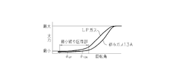
- FIG. 5 is a graph showing the relationship between the rotation angle of the rotating disk 22 according to the present embodiment and the thermal power.
- the minimum throttle flow section 24a is opposed to the fixed side communication hole 23.
- the magnitude of the gas flow rate supplied to the gas burner 300 through the intermediate gas flow rate with the intermediate throttle section 24b facing the fixed side communication hole 23 up to the maximum gas flow rate with the opening 24c facing the fixed side communication hole 23 is set. It can be controlled continuously. Thereby, as shown in FIG. 5, the thermal power can be continuously switched from the minimum thermal power to the maximum thermal power.
- the minimum throttle section 24a is constituted by a narrow groove having the same width and the same depth, the change amount of the thermal power with respect to the change amount of the rotation angle of the rotary disk 22 is gentle. That is, a small change region in which the gas amount change is small with respect to the rotation amount of the motor 30 can be realized. Therefore, the influence on the gas amount accuracy can be reduced and the motor stop error can be allowed. Therefore, the optimum minimum gas flow rate can be accurately controlled in a stable state according to various gas types and combinations of gas burners.
- the intermediate throttle section 24b is configured by a groove in which at least one of the width and the depth gradually changes, the amount of change in the thermal power with respect to the amount of change in the rotation angle of the rotary disk 22 becomes large. ing. Therefore, after the intermediate thermal power that does not require the thermal power accuracy as much as the minimum thermal power (minimum gas flow rate), the responsiveness of the variation in the thermal power with respect to the rotation amount of the rotating disk 22 can be improved.
- the intermediate throttle section 24b has a structure in which the depth of the groove is constant and the width is gradually changed. Further, since the maximum heating power is determined by the size of the nozzle 200 of the gas appliance, the opening 24c only needs to have a passage area that does not cause pressure loss.
- FIG. 6 is a graph showing the relationship between the rotation angle of the rotary disk 22 and the passage area according to the present embodiment.
- FIG. 6 shows three graphs relating to the passage area of the gas control valve 100, the passage area of the nozzle 200 of the gas appliance, and the effective area (described later) formed by these two throttles.
- the graph relating to the passage area of the gas control valve 100 shows I) to IV depending on the position of the minimum throttle section 24a, intermediate throttle section 24b, opening 24c and fixed side communication hole 23 of the rotation side communication hole 24. ) Are divided into four areas (described later).
- the effective area represents a gas passage area when a series throttle including the gas control valve 100 (variable throttle) and the nozzle 200 (fixed throttle) is regarded as one throttle as a whole.
- the gas flow rate is proportional to the effective area.
- LP gas and city gas 13A are exemplified as gas types to be used.
- the minimum gas flow rate is determined by LP gas
- the maximum gas flow rate is determined by city gas 13A. This is because when the same calorific value is obtained as the gas stove, the gas flow rate becomes LP gas ⁇ city gas 13A.
- the throttle area of the gas control valve 100 is sufficiently smaller than the throttle area of the nozzle 200, the minimum gas flow rate is determined on the gas control valve 100 side.
- the restriction in the LP gas of a general household stove is about ⁇ 0.3.
- the maximum gas flow rate is determined by the area of the nozzle 200.
- the throttle is opened to about ⁇ 3 on the gas control valve 100 side. Therefore, the throttle performance ( ⁇ 0.3 to ⁇ 3) required for the gas control valve 100 is about 1/100 in terms of area ratio. The amount of change in the throttle area increases exponentially as the minimum gas flow rate becomes the maximum gas flow rate.
- the control position of the minimum gas flow rate does not depend on the throttle area, that is, a passage area larger than ⁇ 0.3 is set, and a desired value corresponding to ⁇ 0.3 orifice is set depending on the magnitude of passage resistance. It is set as the structure which restrict
- (I) is an area where the minimum throttle section 24a and the fixed side communication hole 23 face each other. In this region, the passage area of the minimum throttle section 24a is constant, but the passage resistance changes according to the length of the non-opposing portion 24a '. By changing the passage resistance, as shown in FIG. 5, a small change region in which the gas amount change is small with respect to the rotation angle of the motor is realized.
- the length of the minimum throttle section 24a will be supplemented.
- the passage length In the case of gas, in order to obtain the effect of the passage resistance that realizes the small change region, the passage length needs to be sufficiently larger than the passage area.
- the ratio of throttle ⁇ (passage area) / passage length is set to 1/20 to 30.
- the minimum throttle section 24a is a groove having a rectangular cross section, but the passage area of the minimum throttle section 24a is converted to ⁇ equivalent for convenience.
- the intermediate throttle section 24b is a composite area that defines the area II) and the area III), and can be said to be a transition area from II) to III).
- the passage area gradually changes.
- the responsiveness is improved by increasing the change in the gas amount with respect to the rotation angle of the motor.
- the gas amount change is increased, as described above, it is necessary to increase the passage area change of the gas control valve 100 exponentially with respect to the rotation angle of the motor as the maximum gas flow rate is approached. Therefore, in the region II), the groove width by the intermediate throttle section 24b is gradually changed, and in the region III), the facing area between the opening 24c and the fixed side communication hole 23 is changed.
- IV is the region where the maximum gas flow rate is achieved. In this region, the entire opening 24 c faces the fixed side communication hole 23. As described above, the maximum gas flow rate is determined on the nozzle 200 side of the gas appliance, but the throttle is opened on the gas control valve 100 side so as not to cause a pressure loss.
- the minimum gas flow rate is adjusted by controlling the position of the minimum throttle section 24a facing the fixed communication hole 23 according to the gas type and gas burner. be able to. Thereby, it is not necessary to prepare many kinds of orifices as dedicated parts different for each gas type and gas burner, and the manufacturing cost and the inventory cost can be greatly reduced. In addition, it is not necessary to replace the orifice when performing gas type conversion, and the work for gas type conversion can be facilitated. Further, according to the present embodiment, it is possible to continuously switch the thermal power from the minimum thermal power to the maximum thermal power. Thereby, the conventional inconvenience that the thermal power adjustment range (thermal power switching stage number) is limited can be solved.
- the fixed side communication hole 23 of the fixed disk 21 is a through hole having a certain opening area
- the rotation side communication hole 24 of the rotary disk 22 is configured to have a shape capable of controlling the gas flow rate.
- the reverse may be possible. That is, the rotation side communication hole of the rotating disk 22 may be a through hole having a certain opening area, and the fixed side communication hole of the fixed disk 21 may be configured to have a shape capable of controlling the gas flow rate.
- the fixed disk 21 corresponds to the disk component of the present invention
- the fixed side communication hole corresponds to the communication hole of the present invention.
- the rotation side communication hole of the rotation side communication hole 24 corresponds to the other side communication hole.
- a correction mechanism that can finely adjust the facing position between the fixed side communication hole 23 and the rotation side communication hole 24 is provided. May be. This is because the manufacturing accuracy of individual parts is limited, and the minimum heating power may not be adjusted with high accuracy so as to satisfy a high required level only by rotating the rotary disk 22 by the motor 30.
- FIG. 7 is a diagram illustrating a configuration example of the correction mechanism.
- FIG. 7 shows an example in which a correction mechanism is provided on the fixed disk 21.
- the fixing disk 21 is provided with a screw hole 40 for fixing it to the main body of the gas control valve 100.
- the shape of the screw hole 40 is not a perfect circle, but is a long circle (long hole) so that the mounting position of the gas control valve 100 with respect to the main body can be adjusted. This screw hole 40 corresponds to a correction mechanism.
- the fine adjustment method of the facing position using the screw hole 40 is as follows. That is, during the assembly process of the gas control valve 100, the fixed disk 21 is temporarily fixed to the main body, and the rotating disk 22 is monitored while monitoring a signal from a position sensor that outputs a signal in synchronization with the rotation of the motor rotating shaft 11. And the minimum throttle section 24a is stopped at the facing position where the minimum gas flow rate is desired to be set.
- the fixed disk 21 is manually rotated with reference to the position of the stopped minimum throttle section 24a (the position indicated by the position sensor synchronized with the motor rotation shaft 11), so that the fixed side communication hole 23 can be rotated.
- the position with respect to the rotation side communication hole 24 is corrected.
- the fixed disk 21 is screwed to the main body.
- anodizing treatment may be performed on at least the contact surface 25 of one of the fixed disk 21 and the rotating disk 22.
- anodizing treatment may be performed on at least the contact surface 25 of one of the fixed disk 21 and the rotating disk 22.
Landscapes
- Engineering & Computer Science (AREA)
- General Engineering & Computer Science (AREA)
- Mechanical Engineering (AREA)
- Chemical & Material Sciences (AREA)
- Combustion & Propulsion (AREA)
- Feeding And Controlling Fuel (AREA)
- Sliding Valves (AREA)
- Taps Or Cocks (AREA)
- Electrically Driven Valve-Operating Means (AREA)
Priority Applications (3)
| Application Number | Priority Date | Filing Date | Title |
|---|---|---|---|
| KR1020157009456A KR20150064082A (ko) | 2012-10-15 | 2013-10-01 | 가스 제어 밸브 및 이것에 사용되는 디스크 부품 |
| CN201380053852.0A CN104755840B (zh) | 2012-10-15 | 2013-10-01 | 燃气控制阀和该燃气控制阀中所使用的盘部件 |
| EP13847007.5A EP2908053A4 (en) | 2012-10-15 | 2013-10-01 | GAS CONTROL VALVE AND DISC COMPONENT THEREWITH |
Applications Claiming Priority (2)
| Application Number | Priority Date | Filing Date | Title |
|---|---|---|---|
| JP2012-228133 | 2012-10-15 | ||
| JP2012228133A JP5960573B2 (ja) | 2012-10-15 | 2012-10-15 | ガス制御弁およびこれに用いるディスク部品 |
Publications (1)
| Publication Number | Publication Date |
|---|---|
| WO2014061441A1 true WO2014061441A1 (ja) | 2014-04-24 |
Family
ID=50488012
Family Applications (1)
| Application Number | Title | Priority Date | Filing Date |
|---|---|---|---|
| PCT/JP2013/076671 Ceased WO2014061441A1 (ja) | 2012-10-15 | 2013-10-01 | ガス制御弁およびこれに用いるディスク部品 |
Country Status (6)
| Country | Link |
|---|---|
| EP (1) | EP2908053A4 (enExample) |
| JP (1) | JP5960573B2 (enExample) |
| KR (1) | KR20150064082A (enExample) |
| CN (1) | CN104755840B (enExample) |
| TW (1) | TWI632326B (enExample) |
| WO (1) | WO2014061441A1 (enExample) |
Cited By (1)
| Publication number | Priority date | Publication date | Assignee | Title |
|---|---|---|---|---|
| CN115750893A (zh) * | 2022-11-10 | 2023-03-07 | 阀源智能科技(杭州)有限公司 | 用于超程保护和阀芯卡滞预警的阀门直行程机构及其方法 |
Families Citing this family (16)
| Publication number | Priority date | Publication date | Assignee | Title |
|---|---|---|---|---|
| ES2552586B1 (es) * | 2014-05-28 | 2016-09-14 | Bsh Electrodomésticos España, S.A. | Válvula reguladora de gas, punto de cocción, y cocina de gas |
| EP3211309B1 (en) | 2016-02-24 | 2019-03-27 | Copreci, S.Coop. | Regulating valve for a gas cooking appliance and gas cooking appliance incorporating said regulating valve |
| ES2738654T3 (es) * | 2016-02-24 | 2020-01-24 | Copreci S Coop | Válvula de regulación para un aparato de cocción de gas y aparato de cocción de gas que incorpora dicha válvula de regulación |
| CN106016266B (zh) * | 2016-07-04 | 2018-10-30 | 珠海格力电器股份有限公司 | 燃气喷嘴及燃烧器 |
| KR101984015B1 (ko) | 2016-12-29 | 2019-09-03 | 공병성 | 비데장치 |
| CN106958666A (zh) * | 2017-04-07 | 2017-07-18 | 宁波方太厨具有限公司 | 内外环流量燃气调节阀 |
| KR20190089270A (ko) | 2018-01-22 | 2019-07-31 | 공병성 | 증기발생기의 설치구조 |
| KR102043462B1 (ko) * | 2018-01-24 | 2019-11-11 | 에스케이매직 주식회사 | 가스레인지 밸브 |
| EP3546831B1 (en) * | 2018-03-26 | 2020-08-26 | Copreci, S.Coop. | Gas cock with a safety valve for a gas cooking appliance, and gas cooking appliance incorporating said gas cock |
| KR102095904B1 (ko) | 2018-12-05 | 2020-04-01 | 공병성 | 증기발생기 |
| JP7343318B2 (ja) * | 2019-05-24 | 2023-09-12 | リンナイ株式会社 | 火力調節弁 |
| JP2021021560A (ja) * | 2019-07-30 | 2021-02-18 | リンナイ株式会社 | コンロバーナ用火力調節装置 |
| CN112303622A (zh) * | 2019-07-30 | 2021-02-02 | 林内株式会社 | 炉具燃烧器用火势调节装置 |
| US20230167909A1 (en) | 2020-04-30 | 2023-06-01 | Turas Gaz Armaturleri Sanayi Ve Ticaret A.S. | A gas valve with rotating disc member |
| KR102241154B1 (ko) | 2020-07-13 | 2021-04-16 | 공병성 | 쑥훈증용 비데장치 |
| CN114110653B (zh) * | 2021-11-25 | 2023-07-21 | 陕西航天西诺美灵电气有限公司 | 一种双通道安全点火机构及方法 |
Citations (6)
| Publication number | Priority date | Publication date | Assignee | Title |
|---|---|---|---|---|
| JPS62137473A (ja) * | 1985-12-06 | 1987-06-20 | Hitachi Ltd | マスフロ−コントロ−ルバルブ |
| JP2632994B2 (ja) * | 1987-07-15 | 1997-07-23 | ロバートショウ コントロールズ カンパニー | 燃料制御器、及び燃料制御器を使用した燃料制御装置、及び燃料制御器を製造する方法 |
| JP2003513220A (ja) * | 1999-11-02 | 2003-04-08 | フィッシャー アンド ペイケル アプライアンシズ リミティド | ガス弁 |
| JP2006153141A (ja) * | 2004-11-29 | 2006-06-15 | Fujikin Inc | エントランスチャンネル付微小流量制御装置。 |
| JP3819307B2 (ja) | 2002-03-04 | 2006-09-06 | リンナイ株式会社 | ガス流量制御装置 |
| JP4128179B2 (ja) | 2005-01-07 | 2008-07-30 | リンナイ株式会社 | 火力調節装置 |
Family Cites Families (10)
| Publication number | Priority date | Publication date | Assignee | Title |
|---|---|---|---|---|
| GB881325A (en) * | 1957-06-05 | 1961-11-01 | Pneumatic Conveyors Huddersfie | Improvements in or relating to liquid flow control valves |
| US3762439A (en) * | 1971-12-06 | 1973-10-02 | Parkland International Inc | Fluid mixing valve assembly |
| DE3012059A1 (de) * | 1980-03-28 | 1981-10-15 | Festo-Maschinenfabrik Gottlieb Stoll, 7300 Esslingen | Pneumatische drosselvorrichtung |
| US4947891A (en) * | 1987-07-15 | 1990-08-14 | Robertshaw Controls Company | Fuel control device, fuel control system using the device and method of making the device |
| JP2000179834A (ja) * | 1998-12-16 | 2000-06-27 | Rinnai Corp | ガスコック装置 |
| JP2008064210A (ja) * | 2006-09-08 | 2008-03-21 | Matsushita Electric Ind Co Ltd | ガス流量制御装置 |
| EP2212596B1 (de) * | 2007-10-17 | 2012-12-12 | BSH Bosch und Siemens Hausgeräte GmbH | Kükenhahn |
| CN201225654Y (zh) * | 2008-04-15 | 2009-04-22 | 宗高雄 | 一种燃气灶具用旋钮点火器 |
| CN101532573B (zh) * | 2009-04-04 | 2011-01-05 | 佛山市顺德生产力促进中心 | 一种耐腐蚀燃气旋塞阀 |
| ES2407559B1 (es) * | 2010-02-23 | 2014-04-29 | Coprecitec, S.L. | Válvula de regulación para un aparato de cocción a gas. |
-
2012
- 2012-10-15 JP JP2012228133A patent/JP5960573B2/ja active Active
-
2013
- 2013-10-01 CN CN201380053852.0A patent/CN104755840B/zh active Active
- 2013-10-01 KR KR1020157009456A patent/KR20150064082A/ko not_active Ceased
- 2013-10-01 WO PCT/JP2013/076671 patent/WO2014061441A1/ja not_active Ceased
- 2013-10-01 EP EP13847007.5A patent/EP2908053A4/en not_active Withdrawn
- 2013-10-15 TW TW102137111A patent/TWI632326B/zh active
Patent Citations (6)
| Publication number | Priority date | Publication date | Assignee | Title |
|---|---|---|---|---|
| JPS62137473A (ja) * | 1985-12-06 | 1987-06-20 | Hitachi Ltd | マスフロ−コントロ−ルバルブ |
| JP2632994B2 (ja) * | 1987-07-15 | 1997-07-23 | ロバートショウ コントロールズ カンパニー | 燃料制御器、及び燃料制御器を使用した燃料制御装置、及び燃料制御器を製造する方法 |
| JP2003513220A (ja) * | 1999-11-02 | 2003-04-08 | フィッシャー アンド ペイケル アプライアンシズ リミティド | ガス弁 |
| JP3819307B2 (ja) | 2002-03-04 | 2006-09-06 | リンナイ株式会社 | ガス流量制御装置 |
| JP2006153141A (ja) * | 2004-11-29 | 2006-06-15 | Fujikin Inc | エントランスチャンネル付微小流量制御装置。 |
| JP4128179B2 (ja) | 2005-01-07 | 2008-07-30 | リンナイ株式会社 | 火力調節装置 |
Non-Patent Citations (1)
| Title |
|---|
| See also references of EP2908053A4 * |
Cited By (2)
| Publication number | Priority date | Publication date | Assignee | Title |
|---|---|---|---|---|
| CN115750893A (zh) * | 2022-11-10 | 2023-03-07 | 阀源智能科技(杭州)有限公司 | 用于超程保护和阀芯卡滞预警的阀门直行程机构及其方法 |
| CN115750893B (zh) * | 2022-11-10 | 2023-07-25 | 阀源智能科技(杭州)有限公司 | 用于超程保护和阀芯卡滞预警的阀门直行程机构及其方法 |
Also Published As
| Publication number | Publication date |
|---|---|
| JP5960573B2 (ja) | 2016-08-02 |
| EP2908053A4 (en) | 2016-05-25 |
| CN104755840A (zh) | 2015-07-01 |
| TW201414964A (zh) | 2014-04-16 |
| CN104755840B (zh) | 2017-03-08 |
| JP2014081108A (ja) | 2014-05-08 |
| EP2908053A1 (en) | 2015-08-19 |
| TWI632326B (zh) | 2018-08-11 |
| KR20150064082A (ko) | 2015-06-10 |
Similar Documents
| Publication | Publication Date | Title |
|---|---|---|
| JP5960573B2 (ja) | ガス制御弁およびこれに用いるディスク部品 | |
| US8875692B2 (en) | Regulation valve | |
| CN108463669B (zh) | 用于燃气灶具的调整阀以及包括所述调整阀的燃气灶具 | |
| CN108463670B (zh) | 用于气体烹饪器具的调节阀和包括调节阀的气体烹饪器具 | |
| TWI551823B (zh) | For the closure of the gas switch | |
| KR101671642B1 (ko) | 연소장치 | |
| JP6051634B2 (ja) | 弁装置および給湯装置 | |
| US20160215975A1 (en) | Gas burner assembly for a gas hob, gas hob and gas oven | |
| JP2017040411A (ja) | 燃焼装置 | |
| CN212537929U (zh) | 具备限流模块的燃气自动调节阀 | |
| CN105927774A (zh) | 一种多功能平衡阀 | |
| US12385646B2 (en) | Control systems and methods for cooktop appliances | |
| CN105509058B (zh) | 高调制范围的混合器以及包括它的预混系统 | |
| JP5753402B2 (ja) | ガス量制御装置 | |
| JP5891710B2 (ja) | 弁装置および給湯装置 | |
| TWM603927U (zh) | 具備限流模組的燃氣自動調節閥 | |
| CN114526353B (zh) | 燃气阀的配气室组件及燃气阀 | |
| GB2417058A (en) | Water mixing valve | |
| JP2012099019A (ja) | 整圧装置 | |
| JP2004069147A (ja) | ガス流量制御装置 | |
| JP2019045076A (ja) | ガス流量制御装置 | |
| JPH11248150A (ja) | 燃焼機器 | |
| JP6517654B2 (ja) | 給湯器 | |
| JP2004101078A (ja) | ガス流量制御装置 | |
| CN201661728U (zh) | 一种燃气比例阀的出气口转换板 |
Legal Events
| Date | Code | Title | Description |
|---|---|---|---|
| 121 | Ep: the epo has been informed by wipo that ep was designated in this application |
Ref document number: 13847007 Country of ref document: EP Kind code of ref document: A1 |
|
| WWE | Wipo information: entry into national phase |
Ref document number: 2013847007 Country of ref document: EP |
|
| ENP | Entry into the national phase |
Ref document number: 20157009456 Country of ref document: KR Kind code of ref document: A |
|
| NENP | Non-entry into the national phase |
Ref country code: DE |