WO2014061152A1 - 光源装置および該光源装置を備えた投写型表示装置 - Google Patents
光源装置および該光源装置を備えた投写型表示装置 Download PDFInfo
- Publication number
- WO2014061152A1 WO2014061152A1 PCT/JP2012/077121 JP2012077121W WO2014061152A1 WO 2014061152 A1 WO2014061152 A1 WO 2014061152A1 JP 2012077121 W JP2012077121 W JP 2012077121W WO 2014061152 A1 WO2014061152 A1 WO 2014061152A1
- Authority
- WO
- WIPO (PCT)
- Prior art keywords
- light source
- cooling air
- source device
- light emitting
- flow path
- Prior art date
Links
Images


Classifications
-
- F—MECHANICAL ENGINEERING; LIGHTING; HEATING; WEAPONS; BLASTING
- F21—LIGHTING
- F21V—FUNCTIONAL FEATURES OR DETAILS OF LIGHTING DEVICES OR SYSTEMS THEREOF; STRUCTURAL COMBINATIONS OF LIGHTING DEVICES WITH OTHER ARTICLES, NOT OTHERWISE PROVIDED FOR
- F21V29/00—Protecting lighting devices from thermal damage; Cooling or heating arrangements specially adapted for lighting devices or systems
- F21V29/50—Cooling arrangements
- F21V29/60—Cooling arrangements characterised by the use of a forced flow of gas, e.g. air
- F21V29/67—Cooling arrangements characterised by the use of a forced flow of gas, e.g. air characterised by the arrangement of fans
-
- F—MECHANICAL ENGINEERING; LIGHTING; HEATING; WEAPONS; BLASTING
- F21—LIGHTING
- F21S—NON-PORTABLE LIGHTING DEVICES; SYSTEMS THEREOF; VEHICLE LIGHTING DEVICES SPECIALLY ADAPTED FOR VEHICLE EXTERIORS
- F21S2/00—Systems of lighting devices, not provided for in main groups F21S4/00 - F21S10/00 or F21S19/00, e.g. of modular construction
-
- G—PHYSICS
- G03—PHOTOGRAPHY; CINEMATOGRAPHY; ANALOGOUS TECHNIQUES USING WAVES OTHER THAN OPTICAL WAVES; ELECTROGRAPHY; HOLOGRAPHY
- G03B—APPARATUS OR ARRANGEMENTS FOR TAKING PHOTOGRAPHS OR FOR PROJECTING OR VIEWING THEM; APPARATUS OR ARRANGEMENTS EMPLOYING ANALOGOUS TECHNIQUES USING WAVES OTHER THAN OPTICAL WAVES; ACCESSORIES THEREFOR
- G03B21/00—Projectors or projection-type viewers; Accessories therefor
- G03B21/14—Details
- G03B21/16—Cooling; Preventing overheating
-
- G—PHYSICS
- G03—PHOTOGRAPHY; CINEMATOGRAPHY; ANALOGOUS TECHNIQUES USING WAVES OTHER THAN OPTICAL WAVES; ELECTROGRAPHY; HOLOGRAPHY
- G03B—APPARATUS OR ARRANGEMENTS FOR TAKING PHOTOGRAPHS OR FOR PROJECTING OR VIEWING THEM; APPARATUS OR ARRANGEMENTS EMPLOYING ANALOGOUS TECHNIQUES USING WAVES OTHER THAN OPTICAL WAVES; ACCESSORIES THEREFOR
- G03B21/00—Projectors or projection-type viewers; Accessories therefor
- G03B21/14—Details
- G03B21/20—Lamp housings
- G03B21/2006—Lamp housings characterised by the light source
- G03B21/2026—Gas discharge type light sources, e.g. arcs
Definitions
- the present invention relates to a light source device having an arc tube and a projection display device provided with the light source device.
- the present invention relates to a light source device that can cool an arc tube.
- An arc tube such as a high-pressure mercury lamp may be used as a light source for a projection display device.
- the arc tube includes a light emitting unit that emits light by discharge, and two sealing units that extend in opposite directions from the light emitting unit.
- the light from the light emitting unit is converted into a light beam traveling in a predetermined direction using a reflector.
- the reflector has a shape that is open by removing the bottom surface of a hollow substantially hemisphere, and surrounds the light emitting portion. Therefore, the reflector reflects the light from the light emitting part to form a light flux that travels in the direction from the top of the reflector toward the open part of the reflector.
- One sealing portion extends to the outside of the reflector through a through hole formed at the top of the reflector, and the other sealing portion is located on the open portion side of the reflector. Since the two sealing portions are aligned along the direction from the top of the reflector toward the opening of the reflector, the light beam formed using the reflector hardly includes a shadow created by the two sealing portions.
- the light beam formed using the reflector is converted into image light using an image forming apparatus, and the image light is projected using a projection lens.
- the arc tube may generate heat with the light emission of the light emitting unit, and the temperature of the arc tube may rise excessively. It is known that when the temperature of the arc tube rises, the luminance of the arc tube decreases and the life of the arc tube is shortened.
- Patent Document 1 Japanese Patent Application Laid-Open No. 2011-48210
- Patent Document 2 Japanese Patent Application Laid-Open No. 2005-10505
- the light source device disclosed in Patent Document 1 includes a blower that generates cooling air (also referred to as a cooling fan) and one duct that guides cooling air from the cooling fan to a light emitting unit.
- cooling air also referred to as a cooling fan
- the cooling air hits the light emitting part through the duct, the light emitting part is cooled.
- the temperature of the arc tube is unlikely to rise, and the brightness of the projection display device is unlikely to decrease.
- Patent Document 2 discloses a light source device capable of cooling a sealing portion extending to the outside of a reflector. More specifically, the reflector is accommodated in a hollow box having a substantially rectangular parallelepiped shape. The cooling air from the cooling fan cools the light emitting part and then flows through the gap between the reflector and the box to cool the sealing part located outside the reflector. According to the light source device disclosed in Patent Literature 2, since the sealing portion is cooled, an increase in the temperature of the arc tube can be further suppressed, and a decrease in luminance of the projection display device can be prevented.
- the arc tube may not be appropriately (uniformly) cooled.
- the temperature of not only the light emitting part but also the sealing part may rise.
- the cooling air is guided outside the light source device after the light emitting unit is cooled. Therefore, the sealing part located outside the reflector is not cooled using the cooling air. For this reason, the temperature of the sealing portion increases.
- the cooling air hits the sealing portion that extends to the outside of the reflector after the light emitting portion is cooled. Since the temperature of the cooling air rises when the cooling air cools the light emitting portion, the temperature of the cooling air hitting the sealing portion is relatively high. Therefore, even if the cooling air hits the sealing portion, the sealing portion is not sufficiently cooled, and the temperature of the sealing portion increases.
- the light emitting unit may not be partially cooled.
- the cooling air for cooling the arc tube flows only in one direction. Therefore, the portion of the arc tube located on the downstream side in the flow direction of the cooling air is not sufficiently cooled, and the temperature of the portion of the arc tube increases.
- An example of the object of the present invention is to provide a light source device capable of cooling the arc tube more appropriately (uniformly).
- One aspect of the present invention includes a reflector, an arc tube, a blower, and first and second ducts.
- the reflector has a through hole.
- the arc tube includes a light emitting part and a sealing part extending from the light emitting part.
- the sealing portion is passed through the through hole of the reflector.
- the blower generates cooling air.
- the first duct guides cooling air to the light emitting unit.
- the second duct guides cooling air to the sealing portion.
- the reflector has a through hole.
- the arc tube includes a light emitting part and a sealing part extending from the light emitting part. The sealing portion is passed through the through hole of the reflector.
- the blower generates cooling air.
- the duct includes a plurality of flow paths that guide the cooling air to different portions of the light emitting unit.
- the flow path selection member selectively causes the cooling air to flow through a predetermined flow path that guides the cooling air to the upper part of the light emitting unit among the plurality of flow paths.
- the predetermined flow path includes a first flow path portion for guiding the cooling air to the first portion of the upper portion of the light emitting unit, and a downstream of the cooling air guided using the first flow path portion. And a second flow path portion for guiding cooling air to a second portion of the upper portion of the light emitting portion located on the side.
- the arc tube can be cooled more appropriately (uniformly).
- FIG. 1 is a perspective view of a projection display device to which a light source device according to the present invention can be applied. It is a perspective view of the main components of a projection type display apparatus. It is the perspective view which looked at the light source main body from the front side. It is the perspective view which looked at the light source main body from the back side. It is a perspective view of the light source device which concerns on the example of this embodiment. It is a perspective view of the light source device of the state which separated the duct from the holding member. It is the perspective view which looked at the holding member from the upper surface side. It is the perspective view which looked at the holding member from the bottom face side. It is a top view of a light source device. It is a bottom view of a light source device.
- FIG. 13 is a cross-sectional view of the light source device on the AA plane shown in FIGS. 11 and 12.
- FIG. 11 is a cross-sectional view of the light source device on the BB plane shown in FIGS. 9 and 10. It is sectional drawing of the light source device in CC plane shown by FIG. 9 and 10. It is sectional drawing of the light source device in the DD plane shown by FIG. 9 and 10.
- FIG. It is sectional drawing of the light source device in the EE surface shown by FIG.
- FIG. 11 is a partial cross-sectional view of the light source device in the FF plane shown in FIGS. 9 and 10.
- FIG. 13 is a cross-sectional view of the light source device on the HH plane shown in FIGS. 11 and 12. It is sectional drawing of the light source device in the II surface shown by FIG.
- FIG. 1 is a perspective view of a projection display device to which the light source device according to this embodiment can be applied.
- the projection display device 1 includes a housing 2.
- An intake port (not shown) is formed on the left side surface of the housing 2, and an exhaust port 4 is formed on the front surface of the housing 2.
- the cooling air flows into the inside of the housing 2 through the air inlet and cools the inside of the housing 2, and then is discharged from the exhaust port 4 to the outside of the housing 2.
- FIG. 2 is a perspective view of main components of the projection display device 1 housed in the housing 2.
- the projection display device 1 includes a light source device 5, an optical engine 6 that forms image light using light from the light source device 5, and image light formed using the optical engine 6.
- a knob 8 for focusing the projection lens 7 is located in the opening 9 formed on the upper surface of the housing 2. The user of the projection display apparatus 1 can focus the projection display apparatus 1 by operating the knob 8.
- an operation unit 10 is provided on the upper surface of the housing 2, and the user can change the on / off of the projection display device 1 and the setting of the projection display device 1 by operating the operation unit 10. it can.
- the projection display device 1 is used in a state where it is placed on a floor or a desk, or is suspended from a ceiling. In a state where the projection display device 1 is placed on the floor, the upper surface of the projection display device 1 faces vertically upward (hereinafter simply referred to as “upward”). In a state where the projection display device 1 is suspended from the ceiling, the upper surface of the projection display device 1 faces vertically downward (hereinafter simply referred to as “downward”).
- the light source device 5 includes a holding member 11 that holds the light source body and a blower 12 that generates cooling air.
- the air inside the housing 2 is sent as cooling air to the holding member 11 by the blower 12 to cool the light source body.
- FIGS. 3 and 4 are perspective views of the light source body held by the holding member 11.
- the light source body 13 includes a hollow arc tube 14, a reflector 15, and a base member 16.
- the base member 16 and the arc tube 14 are attached to the reflector 15 using an adhesive mainly composed of an inorganic material.
- the arc tube 14 includes a substantially spherical light emitting portion 17 that emits light by discharge, and first and second sealing portions 18 and 19 that seal the opening of the light emitting portion 17.
- An electrode (not shown) is arranged inside the light emitting unit 17.
- the first and second sealing portions 18 and 19 extend in opposite directions from the light emitting portion 17, and a foil-like conductive member (not shown) is provided inside the first and second sealing portions 18 and 19. Is arranged. Electric power is supplied to the electrode inside the light emitting unit 17 through the foil-like conductive member.
- the conductive member is drawn out from the first and second sealing portions 18 and 19.
- the portions of the first and second sealing portions 18 and 19 from which the conductive member is drawn out are sealed so that the gas in the arc tube 14 does not leak.
- the arc tube 14 is made of glass, for example, and the conductive member is made of metal, for example.
- An example of such an arc tube 14 is an ultra high pressure mercury lamp.
- the reflector 15 forms a light beam that reflects light from the light emitting unit 17 and travels in a predetermined direction.
- the reflector 15 is an ellipsoidal mirror. The light reflected by the reflector 15 travels toward the open portion of the reflector 15.
- the open side of the reflector is the front surface of the light source body 13 and the light source device 5
- the top side of the reflector (the side on which the arc tube 14 is attached) is the back surface of the light source body 13 and the light source device 5.
- 3 is a perspective view of the light source body 13 viewed from the front side
- FIG. 4 is a perspective view of the light source body 13 viewed from the back side.
- a through hole is formed at the top of the reflector 15.
- the first sealing portion 18 is passed through the through hole, and the second sealing portion 19 is located on the open portion side of the reflector 15. Since the first and second sealing portions 18 and 19 are arranged along the direction from the top of the reflector 15 toward the opening portion of the reflector 15, the light flux formed by the reflector 15 is the first and second sealing portions. It contains almost no shadows made by 18,19.
- the reflector 15 is not limited to an ellipsoidal mirror.
- a parabolic mirror may be used as long as it has a shape capable of forming a light beam that travels in a predetermined direction from light emitted radially from the light emitting unit 17.
- FIG. 5 is a perspective view of the light source device 5 according to the present embodiment
- FIG. 6 is an exploded perspective view of the light source device 5.
- the light source device 5 includes a duct unit 20 that guides cooling air from the blower 12 (see FIG. 2).
- the blower and the duct unit 20 are connected by another duct.
- FIG. 7 is a perspective view of the holding member 11 as viewed from obliquely above
- FIG. 8 is a perspective view of the holding member 11 as viewed from obliquely below.
- FIG. 7 shows the front, top, and right side of the light source device 5
- FIG. 8 shows the front, bottom, and right side of the light source device 5.
- FIG. 9 is a plan view of the light source device 5, and FIG. 10 is a bottom view of the light source device 5.
- FIG. 11 is a right side view of the light source device 5, and
- FIG. 12 is a left side view of the light source device 5.
- FIG. 13 is a cross-sectional view of the light source device 5 in the AA plane shown in FIGS. 11 and 12, and FIG. 14 is a cross-sectional view of the light source device 5 in the BB plane shown in FIGS.
- FIG. 11 is a cross-sectional view of the light source device 5 in the CC plane shown in FIGS. 9 and 10.
- 16 is a cross-sectional view of the light source device 5 in the DD plane shown in FIGS. 9 and 10
- FIG. 17 is a cross-sectional view in the EE plane shown in FIGS. 18 is a cross-sectional view taken along the plane FF shown in FIGS.
- the top and bottom surfaces of the light source device 5 are defined, but these do not define the vertical direction of the light source device 5.
- the light source device 5 may be used with the upper surface shown in FIG. 7 facing downward.
- the upper surface of the light source device 5 is positioned on the upper surface side of the projection display device 1 (see FIG. 1), and the lower surface of the light source device 5 is positioned on the bottom surface side of the projection display device 1. Suppose you are.
- the duct unit 20 includes a first duct 21 that guides cooling air from the blower 12 (see FIG. 2) to the light emitting unit 17.
- the first duct 21 includes a plurality of flow paths 22 and 23 that respectively guide cooling air to different portions of the light emitting unit 17.
- the channel 22 includes a first channel portion 24 and a second channel portion 25, and the channel 23 includes a third channel portion 26 and a fourth channel portion 27.
- the light emitting unit 17 is divided into four parts and two directions are defined.
- the portions of the light emitting unit 17 located on the upper surface side and the right side surface of the light source device 5 are defined as first portions 17 a, and the light emitting unit 17 located on the upper surface side and the left side surface side of the light source device 5.
- the part be the second part 17b.
- part of the light emission part 17 located in the bottom face side and right side surface side of the light source device 5 is made into the 3rd site
- the direction from the right side to the left side of the light source device 5 is defined as a first direction D1, and the direction from the top surface to the bottom side of the light source device 5 is defined as a second direction D2.
- the thick arrows in FIG. 13 indicate the flow of cooling air through the first flow path portion 24, and the thick arrows in FIGS. 15 and 17 indicate the flow of cooling air through the second flow path portion 25. Show.
- the thick arrows in FIGS. 16 and 18 indicate the flow of cooling air passing through the first and second flow path portions 24 and 25.
- the first flow path portion 24 guides the cooling air from the blower 12 (see FIG. 2) to the first portion 17a along the first direction D1. Most of the cooling air flowing into the first flow path portion 24 hits the first portion 17a, and mainly cools the first portion 17a.
- the third portion 17c is slightly cooled by the cooling air.
- the third flow path portion 26 guides the cooling air to the third portion 17c along the first direction D1. Most of the cooling air flowing into the third flow path portion 26 hits the third portion 17c and mainly cools the third portion 17c.
- the first portion 17a is slightly cooled by the cooling air.
- the second flow path portion 25 guides the cooling air from the blower 12 (see FIG. 2) to the second portion 17b along the second direction D2. Most of the cooling air flowing into the second flow path portion 25 hits the second portion 17b and mainly cools the second portion 17b. In other words, the cooling air guided by the second flow path portion 25 cools the second portion 17b located on the downstream side of the cooling air guided using the first flow path portion 24.
- the fourth flow path portion 27 guides the cooling air from the blower to the fourth portion 17d along the second direction D2. Most of the cooling air flowing into the fourth flow path portion 27d hits the fourth portion 17d and mainly cools the fourth portion 17d. In other words, the cooling air guided by the fourth flow path portion 27 cools the fourth portion 17 d located on the downstream side of the cooling air guided using the third flow path portion 26.
- the outlet 28 of the first flow path portion 24 is located on the right side of the light source device 5 with respect to the arc tube 14, and the outlet 29 of the second flow path portion 25 is the arc tube 14. It is located on the upper surface side of the light source device 5.
- the ejection port 30 of the third flow path portion 26 is located on the right side of the light source device 5 with respect to the arc tube 14 and on the bottom surface side of the light source device 5 with respect to the ejection port 28. Further, the outlet 31 of the fourth flow path portion 27 is located on the bottom surface side of the light source device 5 with respect to the arc tube 14.
- the light source device 5 includes a discharge port 32 disposed on the left side of the light source device 5 with respect to the arc tube 14. The cooling air blown from the discharge ports 28 to 31 is discharged from the discharge port 32 after cooling the light emitting unit 17.
- the duct unit 20 includes a common flow path portion 37 that communicates with the intake ports 33 to 36 of the first to fourth flow path portions 24 to 27.
- the intake port 38 of the common flow path portion 37 communicates with the blowout port of the blower 12 (FIG. 2). Therefore, the cooling air from the blower 12 is divided into the first to fourth flow path portions 24 to 27 through the common flow path portion 37.
- a channel selection member 39 is disposed in the common channel portion 37.
- the intake ports 34, 33, 35, and 36 are arranged in this order from the upper surface of the light source device 5 toward the lower surface of the light source device 5.
- the flow path selection member 39 is provided so as to be rotatable about a rotation axis extending between the intake ports 33 and 35 in the first direction D1.
- the flow path selection member 39 is rotated by its own weight, and closes either the intake ports 33 and 34 or the intake ports 35 and 36. That is, the flow path selection member 39 selectively allows the cooling air to flow through the predetermined flow path portion from the first to fourth flow path portions 24 to 27.
- the flow path selection member 39 has intakes 35 and 36. Block. Therefore, the cooling air from the blower 12 (see FIG. 2) flows through the first and second flow path portions 24 and 25. Then, the cooling air is ejected from the ejection ports 28 and 29.
- the cooling air ejected from the ejection port 28 mainly cools the first part 17a and slightly cools the third part 17c.
- the cooling air blown from the blowout port 29 cools the second portion 17b.
- the fourth portion 17d is slightly cooled by the cooling air that has cooled the second portion 17b and the cooling air that has cooled the third portion 17c.
- FIGS. 16 and 18 illustrate the flow of cooling air that cools the light emitting unit 17 in a state where the projection display device 1 (see FIG. 1) is suspended from the ceiling. Note that FIGS. 16 and 18 show only the flow of cooling air in a state where the projection display device 1 is placed on the floor.
- the flow path selection member 39 closes the intake ports 33 and 34. Therefore, the cooling air from the blower 12 (see FIG. 2) flows through the third and fourth flow path portions 26 and 27. Then, the cooling air is ejected from the ejection ports 30 and 31.
- the cooling air blown from the outlet 30 mainly cools the third portion 17c and slightly cools the first portion 17a. Moreover, the cooling air blown out from the blowout port 31 cools the fourth portion 17d.
- the second portion 17b is slightly cooled by the cooling air that has cooled the first portion 17a and the cooling air that has cooled the fourth portion 17d.
- the temperature inside the light emitting unit 17 increases with discharge. And the arc accompanying a discharge curves in the direction opposite to the direction of gravity. Therefore, the temperature of the upper part of the light emitting unit 17 is higher than that of the lower part of the light emitting unit 17.
- the flow path selection member 39 moves according to the installation state of the projection display device 1.
- part 17c is mainly cooled with the cooling air which ejected from the ejection port 28 or the ejection port 30.
- the second portion 17b or the fourth portion 17d is cooled by the cooling air blown from the blowout port 29 or the blowout port 31. Accordingly, a partial increase in temperature of the light emitting unit 17 can be suppressed.
- the second and fourth portions 17b and 17d may not be sufficiently cooled. This is because the cooling air jetted from the jet outlet 28 or the jet outlet 30 increases its temperature by cooling the first part 17a or the third part 17c. In addition, the cooling air hits the first part 17a or the third part 17c, so that the cooling air flows away from the second part 17b or the fourth part 17d.
- the cooling air blown from the blowout port 29 or the blowout port 31 strikes the second part 17b or the fourth part 17d without hitting the first part 17a and the third part 17c. Therefore, the cooling air flows toward the second part 17b or the fourth part 17d with a relatively low temperature, so that the second part 17b or the fourth part 17d is sufficiently cooled.
- ⁇ Suppressing the partial temperature rise of the light emitting unit 17 makes the light emitting unit 17 white and less turbid and extends its life. Further, since the lower part of the light emitting part 17 is not cooled much as compared with the upper part of the light emitting part 17, it is difficult for the luminance to be reduced and the light to be blinked, and the arc tube 14 is not easily blackened, thereby extending its life. Further, by appropriately flowing cooling air to the lower part of the light emitting part, the temperature rise is suppressed, the light emitting part 17 becomes white and hardly turbid, and its life is extended.
- the flow dividing wall 40 is provided between the intake port 33 and the intake port 34 and between the intake port 35 and the intake port 36.
- the ratio of the cooling air volume between the first and second flow path portions 24 and 25 and the ratio of the cooling air volume between the third and fourth flow path portions 26 and 27 by the flow path dividing wall. Can be optimized. Further, the flow of the cooling air flowing through the first to fourth flow path portions 24 to 27 can be adjusted, and the pressure loss can be reduced.
- FIG. 19 is a cross-sectional view of the light source device 5 in the GG plane shown in FIGS. 9 and 10, and FIG. 20 is a cross-sectional view of the light source device 5 in the HH plane shown in FIGS.
- the duct unit 20 includes a second duct 41 that guides cooling air from the blower 12 (see FIG. 2) to the first sealing portion 18.
- the second duct 41 is located on the opposite side of the reflector 15 from the side where the light emitting unit 17 is located.
- the cooling air from the blower 12 hits the first sealing portion 18 through the second duct 41. As a result, the first sealing portion 18 is cooled.
- the cooling air from the blower 12 hits the first sealing portion 18 without hitting the light emitting portion 17, so that the first sealing portion 18 is sufficiently cooled.
- the temperature of the sealed portion between the first sealing portion 18 and the conductive member is unlikely to rise, and the arc tube 14 can be prevented from being ruptured or the arc tube 14 not being lit.
- the ejection part 42 of the second duct 41 is brought closer to the first sealing part 18.
- the first sealing portion 18 can be more efficiently cooled with the cooling air having a smaller air volume. it can.
- it is possible to prevent an increase in noise associated with an increase in size of the blower 12 (see FIG. 2) and an increase in the amount of cooling air.
- All the flow paths for cooling air from the blower 12 (see FIG. 2) to the first sealing portion 18 may not be formed by the second duct 41.
- a part of the flow path may be formed using an air guide wall 44 extending from the outlet 43 of the second duct 41 to the vicinity of the first sealing portion 18. By using the air guide wall 44, the diffusion of the cooling air can be suppressed.
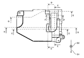
- FIG. 21 is a cross-sectional view of the light source device 5 along the II plane shown in FIGS.
- thick arrows indicate the flow of cooling air.
- the duct unit 20 includes a third duct 45 that guides cooling air from the blower 12 (see FIG. 2) to the second sealing portion 19.
- the outlet 46 of the third duct 45 is located between the outlets 28 and 30.
- the cooling air from the blower 12 hits the second sealing portion 19 through the third duct 45. As a result, the second sealing portion 19 is cooled. The cooling air after cooling the second sealing portion 19 is discharged from the discharge port 32.
- the temperature of the sealing part between the 2nd sealing part 19 and the electrically-conductive member pulled out from the 2nd sealing part 19 can be prevented from rising, and the arc tube 14 can be prevented from rupturing and the arc tube 14 not being lit.
- the cooling air ejected from the ejection port 46 becomes more difficult to diffuse, and more cooling air strikes the second sealing portion 19.
- the second duct 41 has two intake ports 47 and 48, and from the intake ports 47 and 48 to the ejection port 43. It has the two flow paths 49 and 50 formed.
- a third duct 45 is located between the two flow paths 49 and 50.
- the two flow paths 49 and 50 of the second duct 41 have equal flow resistance.
- the distribution of the amount of cooling air blown from the blow-out port 43 does not vary.
- the first sealing portion 18 is cooled more uniformly with respect to a direction (for example, the vertical direction) intersecting the traveling direction of the cooling air ejected from the ejection portion 42.
- the temperature inside the light emitting unit 17 increases with discharge. And the arc accompanying a discharge curves in the direction opposite to the direction of gravity. Therefore, the temperature of the upper part of the light emitting unit 17 is higher than that of the lower part of the light emitting unit 17.
- the upper part and the lower part of the arc tube 14 change depending on the direction of the light source device 5. For example, when the upper surface of the light source device 5 faces upward, the portion on the upper surface side of the arc tube 14 is the upper portion, and the temperature of the portion is likely to rise. When the bottom surface of the light source device 5 faces upward, a portion on the bottom surface side of the arc tube 14 is an upper portion, and the temperature of the portion is likely to rise.
- the ability to cool the light emitting unit 17 in two installation postures is equal.
- the air volume distribution at the intake port 38 of the common flow path portion 37 may be different between when placed on the floor and when suspended from the ceiling.
- the channel resistance of the channel 49 is small and the channel resistance of the channel 50 is large.
- the amount of air flowing through the channel 49 increases and the amount of air flowing through the channel 50 decreases.
- the intake port 34 located near the intake port 47 of the flow channel 49 is reduced, and the intake port 33 located near the intake port 48 of the flow channel 50.
- the amount of air flowing into the air increases.
- the amount of air that cools the first portion 17a from the horizontal direction increases, and the amount of air that cools the second portion 17b from the vertical direction decreases.
- the amount of air flowing into the intake port 35 located near the intake port 47 of the flow channel 49 is reduced and flows into the intake port 36 located near the intake port 48 of the flow channel 50.
- the amount of air that cools the third portion 17c from the horizontal direction decreases, and the amount of air that cools the fourth portion 17d from the vertical direction increases.
- the balance between the amount of air that cools the light emitting unit 17 from the horizontal direction and the amount of air that cools the light emitting unit 17 from the vertical direction changes depending on whether it is placed on the floor or suspended from the ceiling, resulting in a difference in the temperature of the light emitting unit.
- the lifetime of one light source is shorter than the other.
- the airflow flowing into the intake ports 47 and 48 of the flow paths 49 and 50 is equal, and does not change when placed on the floor or suspended from the ceiling.
- the cooling capacity of the light emitting unit 17 is not affected, and a difference in the light source lifetime due to the installation posture is prevented.
- the flow paths 49 and 50 pass through an intermediate point between the intake ports 47 and 48 and are directed from the intake port 47 to the intake port 48. What is necessary is just to be symmetric about the virtual plane which intersects perpendicularly.
- the “symmetry with respect to the virtual plane” mentioned here includes the case where the symmetry of the shape is lost to such an extent that a clear difference in the cooling capacity does not occur.
- the second duct 41 may include two or more flow paths.
- the second duct 41 may have one intake port and one ejection port, and one flow path formed from the intake port to the ejection port.
- the duct unit 20 and the blower 12 are not shaded.
- the part of the duct unit 20 where the flow direction of the cooling air changes is arcuate.
- the flow resistance of the cooling air can be reduced by making the part arc.
- the first duct 21 may have a structure that is not divided into the flow paths 22 and 23 and that simply guides the cooling air from the blower to the light emitting unit 17. Even if the first duct 21 has such a structure, the light emitting portion is cooled and the first sealing portion 18 is cooled. Therefore, the arc tube 14 can be cooled more uniformly.
- the duct unit 20 may be provided with only the first duct 21 including the first to fourth flow path portions 24 to 27 and the flow path selection member 39. Even in this form, each portion 17a to 17b of the light emitting unit 17 is cooled more efficiently. Therefore, the arc tube 14 can be cooled more appropriately.
- the duct unit 20 is in communication with the first to fourth flow path portions 24 to 27, the second duct 41, and the third duct 45 to the blower opening of one blower 12. desirable.
- the number of blowers 12 is reduced, the light source device 5 becomes smaller, and the manufacturing cost of the light source device 5 is reduced.
Landscapes
- Physics & Mathematics (AREA)
- General Physics & Mathematics (AREA)
- Engineering & Computer Science (AREA)
- General Engineering & Computer Science (AREA)
- Arrangement Of Elements, Cooling, Sealing, Or The Like Of Lighting Devices (AREA)
- Projection Apparatus (AREA)
Abstract
発光管をより均一に冷却することができる光源装置を提供する。 光源装置は、リフレクタ(15)と発光管(14)と送風機(12)と第1のダクト(21)と第2のダクト(41)とを備える。リフレクタ(15)は貫通孔を有する。発光管(14)は、発光部(17)および発光部(17)から延びる封止部(18)を含む。そして、封止部(18)は貫通孔に通されている。送風機(12)は冷却風を発生する。第1のダクト(21)は冷却風を発光部(17)に誘導する。第2のダクト(41)は冷却風を封止部(18)に誘導する。
Description
本発明は、発光管を有する光源装置、および当該光源装置を備えた投写型表示装置に関する。特に、発光管を冷却することができる光源装置に関する。
画像を投写する投写型表示装置が知られている。投写型表示装置の光源として、高圧水銀ランプといった発光管が用いられることがある。発光管は、放電により光を発する発光部と、発光部から互いに反対方向に延びる2つの封止部と、を含む。
投写型表示装置では、発光部からの光は、リフレクタを用いて所定の方向に進む光束に変えられる。具体的には、リフレクタは、中空の略半球体の底面を除去して開放した形状を有し、発光部を取り囲んでいる。したがって、リフレクタは、発光部からの光を反射することによってリフレクタの頂部からリフレクタの開放部へ向かう方向に進む光束を形成する。
一方の封止部はリフレクタの頂部に形成された貫通孔を通ってリフレクタの外側まで延びており、他方の封止部はリフレクタの開放部側に位置している。2つの封止部がリフレクタの頂部からリフレクタの開放部へ向かう方向に沿って並んでいるため、リフレクタを用いて形成される光束は、2つの封止部によって作られる影をほとんど含まない。
リフレクタを用いて形成された光束は画像形成装置を用いて画像光に変えられ、当該画像光は投写レンズを用いて投写される。
ところで、発光部の発光に伴って発光管は熱を生じ、発光管の温度が過度に上昇することがある。発光管の温度が上昇すると、発光管の輝度が低下したり発光管の寿命が短くなったりすることが知られている。
発光管の輝度が低下すると、投写型表示装置の輝度が低下してしまう。また、発光管の寿命が短くなると、発光管の交換頻度が増えてしまう。そこで、発光管を冷却することができる光源装置が提案されている。
発光管を冷却することができる光源装置の一例が特開2011-48210号公報(以下、「特許文献1」と称す)および特開2005-10505号公報(以下、「特許文献2」と称す)に開示されている。
特許文献1に開示の光源装置は、冷却風を発生する送風機(冷却ファンとも呼ばれる)と、冷却ファンからの冷却風を発光部に誘導する1つのダクトと、を備える。冷却風がダクトを通って発光部に当たることにより発光部が冷却される。その結果、発光管の温度が上昇しにくくなり、投写型表示装置の輝度が低下しにくくなる。
特許文献2は、リフレクタの外側まで延びている封止部を冷却することができる光源装置を開示している。より具体的には、リフレクタは中空の略直方体形状を有する箱体内に収容されている。冷却ファンからの冷却風は、発光部を冷却した後にリフレクタと箱体との間の隙間を流れてリフレクタの外側に位置する封止部を冷却する。特許文献2に開示の光源装置によれば、当該封止部が冷却されるため、発光管の温度の上昇をより抑制することができ、投写型表示装置の輝度の低下を防ぐことができる。
しかしながら、特許文献1,2に開示されている光源装置では、発光管が適切(均一)に冷却されないことがあった。
例えば、発光管の種類によっては、発光部だけでなく封止部の温度も上昇することがある。
特許文献1に開示の光源装置では、冷却風は、発光部の冷却後、光源装置外に誘導される。したがって、リフレクタの外側に位置する封止部は冷却風を用いて冷却されない。そのため、当該封止部の温度が上昇してしまう。
特許文献2に開示の光源装置では、冷却風は、発光部を冷却した後にリフレクタの外側まで延びている封止部に当たる。冷却風が発光部を冷却する際に冷却風の温度が上がるため、封止部に当たる冷却風は比較的温度が高い。したがって、冷却風が封止部に当たっても封止部は十分に冷却されず、当該封止部の温度が上昇してしまう。
また例えば、発光部を冷却する冷却風の向きによっては、発光部が部分的に冷却されないことがある。より具体的には、特許文献1,2では、発光管を冷却する冷却風は一方向にしか流れない。したがって、冷却風の流れ方向に関して下流側に位置する発光管の部位が十分に冷却されず、発光管の当該部位の温度が上昇してしまう。
以上のように、特許文献1,2に開示されている光源装置では、発光管の温度が部分的に上昇する。その結果、発光管の輝度が低下し投写型表示装置の輝度が低下するとともに、発光管の寿命が短くなって発光管の交換頻度が増えてしまう虞があった。
本発明の目的の一例は、発光管をより適切(均一)に冷却することができる光源装置を提供することにある。
本発明の一つの態様は、リフレクタと、発光管と、送風機と、第1および第2のダクトと、を備える。リフレクタは貫通孔を有する。発光管は、発光部、および発光部から延びる封止部を含む。そして、封止部はリフレクタの貫通孔に通されている。送風機は冷却風を発生する。第1のダクトは冷却風を発光部に誘導する。第2のダクトは冷却風を封止部に誘導する。
本発明の他の態様は、リフレクタと、発光管と、送風機と、ダクトと、流路選択部材と、を備える。リフレクタは貫通孔を有する。発光管は、発光部、および発光部から延びる封止部を含む。そして、封止部はリフレクタの貫通孔に通されている。送風機は冷却風を発生する。ダクトは、発光部のそれぞれ異なる部位に冷却風をそれぞれ誘導する複数の流路を含む。流路選択部材は、複数の流路のうち、発光部の上部に冷却風を誘導する所定の流路に冷却風を選択的に流通させる。そして、所定の流路は、発光部の上部のうちの第1の部位に冷却風を誘導する第1の流路部分と、該第1の流路部分を用いて誘導された冷却風の下流側に位置する発光部の上部のうちの第2の部位に冷却風を誘導する第2の流路部分と、を含む。
本発明によれば、発光管をより適切(均一)に冷却することができる。
次に、本発明の実施形態例について、図面を参照して説明する。
図1は、本実施形態例に係る光源装置を適用可能な投写型表示装置の斜視図である。図1に示されるように、投写型表示装置1は筐体2を備える。筐体2の左側面には吸気口(不図示)が形成されており、筐体2の正面には排気口4が形成されている。冷却風は吸気口を通って筐体2の内部に流入して筐体2の内部を冷却し、その後、排気口4から筐体2の外部へ排出される。
図2は、筐体2の内部に収容されている、投写型表示装置1の主要な部品の斜視図である。図2に示すように、投写型表示装置1は、光源装置5と、光源装置5からの光を用いて画像光を形成する光学エンジン6と、光学エンジン6を用いて形成された画像光を投写する投写レンズ7と、を備える。
図1および2を参照するとわかるように、投写レンズ7の焦点を合わせるためのつまみ8が筐体2の上面に形成された開口9に位置している。投写型表示装置1のユーザはつまみ8を操作することによって投写型表示装置1の焦点を合わせることができる。
また、筐体2の上面には操作部10が設けられており、ユーザは操作部10を操作することによって投写型表示装置1のon/offや、投写型表示装置1の設定を変えることができる。
投写型表示装置1は、床や机に置かれた状態、または天井から吊り下げられた状態で使用される。投写型表示装置1が床に置かれた状態では、投写型表示装置1の上面が鉛直上方(以下、単に「上方」と称す)を向く。投写型表示装置1が天井から吊り下げられた状態では、投写型表示装置1の上面が鉛直下方(以下、単に「下方」と称す)を向く。
光源装置5は、光源本体を保持する保持部材11と、冷却風を発生する送風機12と、を含む。送風機12によって筐体2の内部の空気が冷却風として保持部材11へ送られ、光源本体が冷却される。
図3および4は保持部材11に保持される光源本体の斜視図である。図3および4に示すように、光源本体13は、中空の発光管14と、リフレクタ15と、ベース部材16と、を含む。無機材料を主成分とした接着剤を用いて、ベース部材16と発光管14がリフレクタ15に取り付けられている。
発光管14は、放電により光を発する略球状の発光部17と、発光部17の開口を封止する第1および第2の封止部18,19を含む。
発光部17の内部には電極(不図示)が配されている。第1および第2の封止部18,19は発光部17から互いに反対方向へ延びており、第1および第2の封止部18,19の内部には箔状の導電部材(不図示)が配されている。箔状の導電部材を介して発光部17の内部の電極に電力が供給される。
前記導電部材は第1および第2の封止部18,19から引き出されている。第1および第2の封止部18,19の、前記導電部材が引き出されている部位は密閉されており、発光管14内の気体が漏れないようになっている。発光管14は例えばガラスからなり、前記導電部材は例えば金属からなる。
このような発光管14としては、例えば超高圧水銀ランプが挙げられる。
リフレクタ15は、発光部17からの光を反射して所定の方向に進む光束を形成する。本実施形態例ではリフレクタ15は楕円面鏡である。リフレクタ15で反射された光はリフレクタ15の開放部へ向かう。
本書の説明において、リフレクタの開放部側を光源本体13や光源装置5の正面とし、リフレクタの頂部側(発光管14が取り付けられている側)を光源本体13や光源装置5の背面とする。図3は光源本体13を正面側から見た斜視図であり、図4は光源本体13を背面側から見た斜視図である。
リフレクタ15の頂部には貫通孔が形成されている。第1の封止部18は当該貫通孔に通されており、第2の封止部19はリフレクタ15の開放部側に位置している。第1および第2の封止部18,19がリフレクタ15の頂部からリフレクタ15の開放部へ向かう方向に沿って並んでいるため、リフレクタ15によって形成さえる光束は第1および第2の封止部18,19によって作られる影をほとんど含まない。
なお、リフレクタ15は、楕円面鏡に限定されない。例えば、放物面鏡であってもよく、発光部17から放射状に発せられる光を所定の方向に進む光束を形成できる形状を有していればよい。
図5は本実施形態例に係る光源装置5の斜視図、図6は光源装置5の分解斜視図である。図5に示すように、光源装置5は、送風機12(図2参照)からの冷却風を誘導するダクトユニット20を含む。なお、本実施形態例では、送風機とダクトユニット20とは、他のダクトで連結している。
図7は保持部材11を斜め上方から見た斜視図であり、図8は保持部材11を斜め下方からみた斜視図である。図7には光源装置5の正面、上面および右側面が示されており、図8には光源装置5の正面、底面および右側面が示されている。
図9は光源装置5の平面図であり、図10は光源装置5の底面図である。図11は光源装置5の右側面図であり、図12は光源装置5の左側面図である。
図13は図11および12に示されるA-A面における光源装置5の断面図であり、図14は図9および10に示されるB-B面における光源装置5の断面図であり、図15は図9および10に示されるC-C面における光源装置5の断面図である。図16は図9および10に示されるD-D面における光源装置5の断面図であり、図17は図9および図10に示されるE-E面における断面図である。図18は図9および10に示されるF-F面における断面図である。
便宜上、光源装置5の上面および底面を定義しているが、これらは光源装置5の上下方向を定めるものではない。例えば、光源装置5は、図7に示される上面が下方を向いた状態で使用されてもよい。また、本実施形態例の説明においては、光源装置5の上面が投写型表示装置1(図1参照)の上面側に位置し、光源装置5の底面が投写型表示装置1の底面側に位置しているものとする。
図13ないし18に示すように、ダクトユニット20は送風機12(図2参照)からの冷却風を発光部17に誘導する第1のダクト21を含む。第1のダクト21は、発光部17のそれぞれ異なる部位に冷却風をそれぞれ誘導する複数の流路22,23を含む。さらに、流路22は第1の流路部分24と第2の流路部分25を含み、流路23は第3の流路部分26と第4の流路部分27を含む。
ここで、本実施形態例の説明を容易にするため、発光部17を4つの部位に分けるとともに、2つの方向を定義する。
図16に示すように、光源装置5の上面側および右側面側に位置する発光部17の部位を第1の部位17aとし、光源装置5の上面側および左側面側に位置する発光部17の部位を第2の部位17bとする。また、光源装置5の底面側および右側面側に位置する発光部17の部位を第3の部位17cとし、光源装置5の底面側および左側面側に位置する発光部17の部位を第4の部位17dとする。
光源装置5の右側面側から左側面側へ向かう方向を第1の方向D1と定義し、光源装置5の上面側から底面側へ向かう方向を第2の方向D2と定義する。
なお、図13中の太矢印は第1の流路部分24を通る冷却風の流れを示しており、図15および17中の太矢印は第2の流路部分25を通る冷却風の流れを示している。図16および18中の太矢印は第1および第2の流路部分24,25を通る冷却風の流れを示している。
図13,16および18に示すように、第1の流路部分24は送風機12(図2参照)からの冷却風を第1の方向D1に沿って第1の部位17aに誘導する。第1の流路部分24に流入したほとんどの冷却風は第1の部位17aに当たり、主に第1の部位17aを冷却する。
ただし、第1の流路部分24に流入した冷却風の全てが第1の部位17aのみに当たるわけではなく、当該冷却風の一部は発光部17よりも光源装置5の底面側を通る。すなわち、第3の部位17cが当該冷却風によって少し冷却される。
第3の流路部分26は冷却風を第1の方向D1に沿って第3の部位17cに誘導する。第3の流路部分26に流入したほとんどの冷却風は第3の部位17cに当たり、主に第3の部位17cを冷却する。
ただし、第3の流路部分26に流入した冷却風の全てが第3の部位17cのみに当たるわけではなく、当該冷却風の一部は発光部17よりも光源装置5の上面側を通る。すなわち、第1の部位17aが当該冷却風によって少し冷却される。
図14,15,16に示すように、第2の流路部分25は送風機12(図2参照)からの冷却風を第2の方向D2に沿って第2の部位17bに誘導する。第2の流路部分25に流入したほとんどの冷却風は第2の部位17bに当たり、主に第2の部位17bを冷却する。言い換えれば、第2の流路部分25によって誘導された冷却風は、第1の流路部分24を用いて誘導された冷却風の下流側に位置する第2の部位17bを冷却する。
第4の流路部分27は送風機からの冷却風を第2の方向D2に沿って第4の部位17dに誘導する。第4の流路部分27dに流入したほとんどの冷却風は第4の部位17dに当たり、主に第4の部位17dを冷却する。言い換えれば、第4の流路部分27によって誘導された冷却風は、第3の流路部分26を用いて誘導された冷却風の下流側に位置する第4の部位17dを冷却する。
本実施形態例では、第1の流路部分24の噴き出し口28は発光管14よりも光源装置5の右側面側に位置し、第2の流路部分25の噴きだし口29は発光管14よりも光源装置5の上面側に位置している。
第3の流路部分26の噴き出し口30は発光管14よりも光源装置5の右側面側かつ噴き出し口28よりも光源装置5の底面側に位置する。また、第4の流路部分27の噴き出し口31は発光管14よりも光源装置5の底面側に位置している。
また、光源装置5は、発光管14よりも光源装置5の左側面側に配された排出口32を含む。噴き出し口28ないし31から噴き出された冷却風は発光部17を冷却した後に排出口32から排出される。
図18に示すように、ダクトユニット20は、第1ないし第4の流路部分24ないし27の取り入れ口33ないし36と通じる共通流路部分37を含む。共通流路部分37の取り入れ口38は送風機12(図2)の噴き出し口と通じている。したがって、送風機12からの冷却風は共通流路部分37を通って第1ないし第4の流路部分24ないし27に分かれる。
共通流路部分37には流路選択部材39が配されている。取り入れ口34,33,35,36はこの順に光源装置5の上側面から光源装置5の下側面に向かって並んでいる。流路選択部材39は取り入れ口33,35の間を第1の方向D1へ延びる回転軸を中心に回転可能に設けられている。
流路選択部材39は、自重によって回転し、取り入れ口33および34、または取り入れ口35および36のいずれか一方を塞ぐ。すなわち、流路選択部材39は、第1ないし第4の流路部分24ないし27のうちから所定の流路部分に冷却風を選択的に流通させる。
投写型表示装置1(図1参照)が床に置かれている状態における、発光部17を冷却する冷却風の流れについて図16および18を用いて説明する。
投写型表示装置1が床に置かれている状態、すなわち光源装置5の上面が上方を向いている状態(図18に示されている状態)では、流路選択部材39は取り入れ口35および36を塞ぐ。したがって、送風機12(図2参照)からの冷却風は第1および第2の流路部分24および25を流れる。そして、冷却風は噴き出し口28および29から噴き出る。
噴き出し口28から噴き出された冷却風は、第1の部位17aを主に冷却し、第3の部位17cを少し冷却する。また、噴き出し口29から噴き出された冷却風は第2の部位17bを冷却する。第4の部位17dは、第2の部位17bを冷却した冷却風や、第3の部位17cを冷却した冷却風によって少し冷却される。
なお、取り入れ口35,36は流路選択部材39によって塞がれているため、噴き出し口30,31から冷却風は噴き出ない。
投写型表示装置1(図1参照)が天井から吊り下げられた状態における、発光部17を冷却する冷却風の流れについて図16および18説明する。なお、図16および18では投写型表示装置1が床に置かれている状態での冷却風の流れしか示されていないので注意されたい。
投写型表示装置1が天井から吊り下げられた状態、すなわち光源装置5の上面が下方を向いている状態では、流路選択部材39は取り入れ口33および34を塞ぐ。したがって、送風機12(図2参照)からの冷却風は第3および第4の流路部分26,27を流れる。そして、冷却風は噴き出し口30,31から噴き出る。
噴き出し口30から噴き出された冷却風は第3の部位17cを主に冷却し、第1の部位17aを少し冷却する。また、噴き出し口31から噴き出された冷却風は第4の部位17dを冷却する。第2の部位17bは、第1の部位17aを冷却した冷却風や、第4の部位17dを冷却した冷却風によって少し冷却される。
なお、取り入れ口33,34は流路選択部材39によって塞がれているため、噴き出し口28,29から冷却風は噴き出ない。
放電に伴って発光部17の内部の温度が上昇する。そして、放電に伴うアークは重力の向きと反対方向に湾曲する。そのため、発光部17の上部は発光部17の下部よりも温度が高くなる。
本実施形態例によれば、投写型表示装置1の設置の状況に応じて流路選択部材39が移動する。そして、噴き出し口28または噴き出し口30から噴き出された冷却風によって第1の部位17aまたは第3の部位17cが主に冷却される。また、噴き出し口29または噴き出し口31から噴き出される冷却風によって第2の部位17bまたは第4の部位17dが冷却される。したがって、発光部17の部分的な温度の上昇を抑制することができる。
特に、噴き出し口29または噴き出し口31に相当する噴き出し口がない光源装置では、第2および第4の部位17b,17dが十分に冷却されないことがある。噴き出し口28または噴き出し口30から噴き出された冷却風は第1の部位17aまたは第3の部位17cを冷却することによってその温度が上昇してしまうためである。また、該冷却風が第1の部位17aまたは第3の部位17cに当たることで、該冷却風が第2の部位17bまたは第4の部位17dから離れる流れになってしまうためである。
本発明によれば、噴き出し口29または噴き出し口31から噴き出された冷却風は、第1の部位17aおよび第3の部位17cに当たることなく第2の部位17bまたは第4の部位17dに当たる。したがって、当該冷却風は比較的低い温度のままで第2の部位17bまたは第4の部位17dに向かって流れるため、第2の部位17bまたは第4の部位17dが十分に冷却される。
発光部17の部分的な温度の上昇を抑制することによって、発光部17が白く濁りにくくなり、その寿命が延びる。また、発光部17の下部は、発光部17の上部に比べてあまり冷却されないため、輝度の低下や光の明滅が生じにくくなるとともに、発光管14が黒くなりにくく、その寿命が延びる。さらに、発光部の下部に適度に冷却風を流すことで、温度の上昇を抑制し、発光部17が白く濁りにくくなり、その寿命が延びる。
取り入れ口33と取り入れ口34との間、および取り入れ口35と取り入れ口36との間に、流路分割壁40を設けておくことがより好ましい。流路分割壁によって、第1および第2の流路部分24,25の間の冷却風の風量の割合や、第3および第4の流路部分26,27の間の冷却風の風量の割合を最適にすることができる。また、第1ないし第4の流路部分24ないし27を流れる冷却風の流れを整えることができ、圧力損失を低減できる。
図19は図9および10に示されるG-G面における光源装置5の断面図であり、図20は図10および11に示されるH-H面における光源装置5の断面図である。
図19および20に示すように、ダクトユニット20は、送風機12(図2参照)からの冷却風を第1の封止部18に誘導する第2のダクト41を含む。第2のダクト41は、リフレクタ15の、発光部17が位置する側とは反対側に位置している。
送風機12からの冷却風は第2のダクト41を通って第1の封止部18に当たる。その結果、第1の封止部18が冷却される。
例えば、第1の封止部18が十分に冷却されない場合、第1の封止部18と、第1の封止部18から引き出された導電部材(不図示)との間の密閉部の温度が上昇する。その結果、前記導電部材の酸化が進み、発光管14が破裂したり発光管14が点灯しなくなったりする。
本実施形態例によれば、送風機12からの冷却風が発光部17に当たることなく第1の封止部18に当たるため、第1の封止部18が十分に冷却される。その結果、第1の封止部18と前記導電部材との間の密閉部の温度が上がりにくくなり、発光管14の破裂や発光管14の不点灯を防ぐことができる。
第2のダクト41の噴き出し部42を第1の封止部18により近づけることが望ましい。このようにすることによって、冷却風が拡散する前に冷却風が第1の封止部18に当たるため、より少ない風量の冷却風で第1の封止部18をより効率的に冷却することができる。その結果、送風機12(図2参照)の大型化や、冷却風の風量の増加に伴う騒音の増大を防ぐことができる。
送風機12(図2参照)から第1の封止部18までの冷却風用の流路の全てが第2のダクト41によって形成されていなくてもよい。例えば、第2のダクト41の噴き出し口43から第1の封止部18付近まで延びる導風壁44を用いて当該流路の一部が形成されていてもよい。導風壁44を用いることにより冷却風の拡散を抑制することができる。
図21は、図11および12に示されるI-I面における光源装置5の断面図である。図15において、太矢印は冷却風の流れを示している。
図19および21に示すように、ダクトユニット20は、送風機12(図2参照)からの冷却風を第2の封止部19へ誘導する第3のダクト45を含む。第3のダクト45の噴き出し口46は噴き出し口28,30の間に位置している。
送風機12からの冷却風は第3のダクト45を通って第2の封止部19に当たる。その結果、第2の封止部19が冷却される。第2の封止部19を冷却した後の冷却風は、排出口32から排出される。
送風機12からの冷却風によって第2の封止部19が冷却されるため、第2の封止部19と、第2の封止部19から引き出された導電部材との間の密閉部の温度が上がりにくくなり、発光管14の破裂や発光管14の不点灯を防ぐことができる。
第3のダクト45の噴き出し口46をより長くすることによって、噴き出し口46から噴き出される冷却風がより拡散しにくくなり、より多くの冷却風が第2の封止部19に当たる。その結果、より少ない風量の冷却風で第2の封止部19をより高い効率で冷却することができ、送風機12(図2参照)の大型化や、冷却風の風量の増加に伴う騒音の増大を防ぐことができる。
本実施形態例では、図5,6,19および20に示されるように、第2のダクト41は、2つの取り入れ口47,48を有し、かつ、取り入れ口47,48から噴き出し口43まで形成された2つの流路49,50を有している。そして、2つの流路49,50の間に第3のダクト45が位置している。
第2のダクト41の2つの流路49,50は等しい流路抵抗を有することが望ましい。流路49,50の流路抵抗を同じにすることによって、噴き出し口43から噴き出される冷却風の風量の分布がばらつかなくなる。その結果、第1の封止部18は、噴き出し部42から噴き出される冷却風の進行方向と交わる方向(例えば鉛直方向)に関してより均一に冷却される。
放電に伴って発光部17の内部の温度が上昇する。そして、放電に伴うアークは重力の向きと反対方向に湾曲する。そのため、発光部17の上部は発光部17の下部よりも温度が高くなる。
そして、光源装置5の向きによって、発光管14の上部と下部が変化する。例えば、光源装置5の上面が上方を向く場合には、発光管14の上面側の部位が上部となり、当該部位の温度が上昇しやすくなる。光源装置5の底面が上方を向く場合には、発光管14の底面側の部位が上部となり、当該部位の温度が上昇しやすくなる。
投写型表示装置1が床に置かれる場合と天井から吊り下げられる場合とで光源寿命を等しくするためには、2つの設置姿勢で発光部17を冷却する能力は等しいことが望ましい。流路49,50の流路抵抗が異なる場合、共通流路部分37の取り入れ口38における風量分布が、床に置かれる場合と天井から吊り下げられる場合で異なる虞がある。
例えば、流路49の流路抵抗が小さく、流路50の流路抵抗が大きいとする。流路49,50の流路抵抗が等しい場合と比較し、流路49に流れる風量が増え、流路50に流れる風量が減る。これにより、床に置かれた場合は、流路49の取り入れ口47に近い場所に位置する取り入れ口34に流入する風量は減り、流路50の取り入れ口48に近い場所に位置する取り入れ口33に流入する風量は増える。水平方向から第1の部位17aを冷却する風量は増え、鉛直方向から第2の部位17bを冷却する風量は減る。天井に吊り下げられた場合は、流路49の取り入れ口47に近い場所に位置する取り入れ口35に流入する風量は減り、流路50の取り入れ口48に近い場所に位置する取り入れ口36に流入する風量は増える。水平方向から第三の部位17cを冷却する風量は減り、鉛直方向から第四の部位17dを冷却する風量は増える。
その結果、床に置かれた場合と天井に吊り下げられた場合とで、発光部17を水平方向から冷却する風量と鉛直方向から冷却する風量のバランスが変わり、発光部の温度に差が生じ、一方の光源寿命が他方より短くなる虞がある。
本実施形態例によれば、流路49,50の取り入れ口47,48に流入する風量は等しく、床に置かれた場合でも天井から吊り下げられた場合でも変わらない。これにより発光部17の冷却能力に影響を及ぼすことはなく、設置姿勢により光源寿命に差が生じることが防がれる。
流路49,50の流路抵抗が同じになる形状としては、例えば、流路49,50が、取り入れ口47,48の間の中間点を通りかつ取り入れ口47から取り入れ口48へ向かう方向と垂直に交わる仮想面に関して対称であればよい。
なお、ここで言う「仮想面に関して対称」には、冷却能力に明確な差が生じない程度に形状の対称性を失っている場合も含む。
また、第2のダクト41は2つ以上の流路を含んでいてもよい。もちろん、第2のダクト41が1つの取り入れ口および1つの噴き出し口と、当該取り入れ口から当該噴き出し口まで形成された1つの流路と、を有していてもよい。
ダクトユニット20や送風機12は、光束の進行経路外に設けておくことが望ましい。ダクトユニット20や送風機12を光束の進行経路外に設けることによって、ダクトユニット20や送風機12の影が作られなくなる。
また、ダクトユニット20の、冷却風の流れ方向が変わる部位を弧状にしておくことが望ましい。当該部位を弧状にしておくことによって冷却風の流れ抵抗を低減することができる。
なお、本発明は、本実施形態例に限定されるものではない。
例えば、第1のダクト21は、流路22,23に分かれていない、単に送風機からの冷却風を発光部17に誘導する構造であってもよい。第1のダクト21がこのような構造を有していても、発光部が冷却されるとともに第1の封止部18が冷却される。したがって、発光管14をより均一に冷却することができる。
また、ダクトユニット20は、第1ないし第4の流路部分24ないし27を含む第1のダクト21、および流路選択部材39のみを備えている形態であってもよい。この形態であっても、発光部17の各部位17aないし17bがより効率的に冷却される。したがって、発光管14をより適切に冷却することができる。
本実施形態例のようにダクトユニット20が第1ないし第4の流路部分24ないし27、第2のダクト41および第3のダクト45が1つの送風機12の送風口と通じていることがより望ましい。送風機12の数が減り、光源装置5がより小型になるとともに光源装置5の製作コストが低減される。
以上、実施例を参照して本願発明を説明したが、本願発明は上記実施例に限定されるものではない。本願発明の形や細部には、本願発明の技術思想の範囲内で当業者が理解し得る様々な変更をすることができる。
1 投写型表示装置
5 光源装置
12 送風機
14 発光管
15 リフレクタ
17 発光部
18 第1の封止部
19 第2の封止部
21 第1のダクト
41 第2のダクト
5 光源装置
12 送風機
14 発光管
15 リフレクタ
17 発光部
18 第1の封止部
19 第2の封止部
21 第1のダクト
41 第2のダクト
Claims (10)
- 貫通孔を有するリフレクタと、
発光部、および該発光部から延びる封止部を含み、該封止部が前記貫通孔に通された発光管と、
冷却風を発生する送風機と、
前記冷却風を前記発光部に誘導する第1のダクトと、
前記冷却風を前記封止部に誘導する第2のダクトと、を備える光源装置。 - 請求項1に記載の光源装置において、
前記第1のダクトが、前記発光部のそれぞれ異なる部位に前記冷却風をそれぞれ誘導する複数の流路を含み、
前記光源装置が、前記第1のダクトの前記複数の流路のうち、前記発光部の上部に前記冷却風を誘導する所定の流路に前記冷却風を選択的に流通させる流路選択部材をさらに備える光源装置。 - 請求項2に記載の光源装置において、
前記流路選択部材は、自重によって鉛直下方に移動して前記複数の流路のうちから前記所定の流路を選択する、光源装置。 - 請求項2または3に記載の光源装置において、
前記所定の流路は、前記発光部の上部のうちの第1の部位に前記冷却風を誘導する第1の流路部分と、該第1の流路部分を用いて誘導された前記冷却風の下流側に位置する前記発光部の上部のうちの第2の部位に前記冷却風を誘導する第2の流路部分と、を含む、光源装置。 - 請求項1ないし4のいずれか1項に記載の光源装置において、
前記発光管が、前記発光部の、第1の前記封止部が位置する側とは反対の側から延びる第2の封止部を含み、
前記光源装置が前記冷却風を前記第2の封止部に誘導する第3のダクトをさらに備える、光源装置。 - 請求項1ないし4のいずれか1項に記載の光源装置において、
前記第2のダクトは、前記冷却風を取り入れる取り入れ口から前記冷却風を噴き出す噴き出し口まで延びる少なくとも2つの流路を含み、
前記第2のダクトの前記少なくとも2つの流路は等しい流路抵抗を有する、光源装置。 - 請求項6に記載の光源装置において、
前記発光管が、前記発光部の、第1の前記封止部が位置する側とは反対の側から延びる第2の封止部を含み、
前記光源装置が、前記第2のダクトの前記少なくとも2つの流路のうちの2つの流路の間に配され、前記冷却風を前記第2の封止部に誘導する第3のダクトをさらに備える、光源装置。 - 貫通孔を有するリフレクタと、
発光部、および該発光部から延びる封止部を含み、該封止部が前記貫通孔に通された発光管と、
冷却風を発生する送風機と、
前記発光部のそれぞれ異なる部位に前記冷却風をそれぞれ誘導する複数の流路を含むダクトと、
前記複数の流路のうち、前記発光部の上部に前記冷却風を誘導する所定の流路に前記冷却風を選択的に流通させる流路選択部材と、
前記所定の流路は、前記発光部の上部のうちの第1の部位に前記冷却風を誘導する第1の流路部分と、該第1の流路部分を用いて誘導された前記冷却風の下流側に位置する前記発光部の上部のうちの第2の部位に前記冷却風を誘導する第2の流路部分と、を含む、光源装置。 - 請求項8に記載の光源装置において、
前記流路選択部材は、自重によって鉛直下方に移動して前記複数の流路のうちから前記所定の流路を選択する、光源装置。 - 請求項1ないし9のいずれか1項に記載の光源装置を備えた投写型表示装置。
Priority Applications (2)
| Application Number | Priority Date | Filing Date | Title |
|---|---|---|---|
| CN201280074556.4A CN104412041A (zh) | 2012-10-19 | 2012-10-19 | 光源装置以及具备该光源装置的投影式显示装置 |
| PCT/JP2012/077121 WO2014061152A1 (ja) | 2012-10-19 | 2012-10-19 | 光源装置および該光源装置を備えた投写型表示装置 |
Applications Claiming Priority (1)
| Application Number | Priority Date | Filing Date | Title |
|---|---|---|---|
| PCT/JP2012/077121 WO2014061152A1 (ja) | 2012-10-19 | 2012-10-19 | 光源装置および該光源装置を備えた投写型表示装置 |
Publications (1)
| Publication Number | Publication Date |
|---|---|
| WO2014061152A1 true WO2014061152A1 (ja) | 2014-04-24 |
Family
ID=50487740
Family Applications (1)
| Application Number | Title | Priority Date | Filing Date |
|---|---|---|---|
| PCT/JP2012/077121 WO2014061152A1 (ja) | 2012-10-19 | 2012-10-19 | 光源装置および該光源装置を備えた投写型表示装置 |
Country Status (2)
| Country | Link |
|---|---|
| CN (1) | CN104412041A (ja) |
| WO (1) | WO2014061152A1 (ja) |
Families Citing this family (1)
| Publication number | Priority date | Publication date | Assignee | Title |
|---|---|---|---|---|
| WO2019021463A1 (ja) * | 2017-07-28 | 2019-01-31 | マクセル株式会社 | 投射型映像表示装置 |
Citations (3)
| Publication number | Priority date | Publication date | Assignee | Title |
|---|---|---|---|---|
| JP2011048210A (ja) * | 2009-08-28 | 2011-03-10 | Hitachi Consumer Electronics Co Ltd | 投射型映像表示装置 |
| WO2011111186A1 (ja) * | 2010-03-10 | 2011-09-15 | Necディスプレイソリューションズ株式会社 | 光源装置および投写型表示装置 |
| JP2012027171A (ja) * | 2010-07-22 | 2012-02-09 | Seiko Epson Corp | 光源装置およびプロジェクター |
Family Cites Families (3)
| Publication number | Priority date | Publication date | Assignee | Title |
|---|---|---|---|---|
| CN100595668C (zh) * | 2007-10-09 | 2010-03-24 | 青岛海信电器股份有限公司 | 投影机灯泡散热方法及结构 |
| CN101702073B (zh) * | 2009-11-05 | 2012-07-18 | 深圳雅图数字视频技术有限公司 | 投影机 |
| JP6039878B2 (ja) * | 2010-03-24 | 2016-12-07 | セイコーエプソン株式会社 | 光源装置及びプロジェクター |
-
2012
- 2012-10-19 CN CN201280074556.4A patent/CN104412041A/zh active Pending
- 2012-10-19 WO PCT/JP2012/077121 patent/WO2014061152A1/ja active Application Filing
Patent Citations (3)
| Publication number | Priority date | Publication date | Assignee | Title |
|---|---|---|---|---|
| JP2011048210A (ja) * | 2009-08-28 | 2011-03-10 | Hitachi Consumer Electronics Co Ltd | 投射型映像表示装置 |
| WO2011111186A1 (ja) * | 2010-03-10 | 2011-09-15 | Necディスプレイソリューションズ株式会社 | 光源装置および投写型表示装置 |
| JP2012027171A (ja) * | 2010-07-22 | 2012-02-09 | Seiko Epson Corp | 光源装置およびプロジェクター |
Also Published As
| Publication number | Publication date |
|---|---|
| CN104412041A (zh) | 2015-03-11 |
Similar Documents
| Publication | Publication Date | Title |
|---|---|---|
| US9366947B2 (en) | Light source device, apparatus for directing cooling air over the light source device, and projector | |
| JP6039878B2 (ja) | 光源装置及びプロジェクター | |
| US8851683B2 (en) | Light source device and projection-type display device | |
| US9285663B2 (en) | Projection display device having light source with plurality of port groups each having opening and closing plate | |
| US9229303B2 (en) | Projector light source having three cooling airflow delivery ports | |
| JP2010078973A (ja) | 光源冷却装置および投写型画像表示装置 | |
| JP5263993B2 (ja) | 光源冷却装置、投写型表示装置、および光源冷却方法 | |
| JP2005107470A (ja) | 光源装置 | |
| WO2014061152A1 (ja) | 光源装置および該光源装置を備えた投写型表示装置 | |
| JP2005173085A (ja) | 光源装置およびこれを用いたプロジェクター | |
| WO2014061120A1 (ja) | 光源装置及び投写型表示装置 | |
| JP2015162391A (ja) | 光源用ハウジング、光源装置、画像投射装置 | |
| JP6288697B2 (ja) | 光源装置、投写型表示装置および光源装置の冷却方法 | |
| JP2007058242A (ja) | 光学装置 | |
| JP2012113073A (ja) | 光源ユニットおよびこれを備えた投射型表示装置 | |
| JP6308577B2 (ja) | 光源装置及びそれを備えた投写型表示装置と光源装置の冷却方法 | |
| JP6061362B2 (ja) | 光源装置及び投写型表示装置 | |
| JP6304741B2 (ja) | ランプユニット、光源装置、投写型表示装置、およびランプ冷却方法 | |
| JP5533129B2 (ja) | 光源装置、およびプロジェクター | |
| JP5794347B2 (ja) | 光源装置、及びプロジェクター | |
| JP2013015654A (ja) | 光源装置及びプロジェクター | |
| JP5366228B2 (ja) | 光源冷却装置、投写型表示装置、および光源冷却方法 | |
| WO2015056336A1 (ja) | 冷却装置、投写型表示装置、および冷却方法 | |
| JP2016109801A (ja) | 光源装置、投写型表示装置、および冷却方法 | |
| US20100067237A1 (en) | Light source device |
Legal Events
| Date | Code | Title | Description |
|---|---|---|---|
| 121 | Ep: the epo has been informed by wipo that ep was designated in this application |
Ref document number: 12886522 Country of ref document: EP Kind code of ref document: A1 |
|
| NENP | Non-entry into the national phase |
Ref country code: DE |
|
| 122 | Ep: pct application non-entry in european phase |
Ref document number: 12886522 Country of ref document: EP Kind code of ref document: A1 |
|
| NENP | Non-entry into the national phase |
Ref country code: JP |