WO2014061124A1 - ディスプレイ装置、及び画像表示方法 - Google Patents
ディスプレイ装置、及び画像表示方法 Download PDFInfo
- Publication number
- WO2014061124A1 WO2014061124A1 PCT/JP2012/076910 JP2012076910W WO2014061124A1 WO 2014061124 A1 WO2014061124 A1 WO 2014061124A1 JP 2012076910 W JP2012076910 W JP 2012076910W WO 2014061124 A1 WO2014061124 A1 WO 2014061124A1
- Authority
- WO
- WIPO (PCT)
- Prior art keywords
- image
- signal
- image signal
- signal level
- color
- Prior art date
- Legal status (The legal status is an assumption and is not a legal conclusion. Google has not performed a legal analysis and makes no representation as to the accuracy of the status listed.)
- Ceased
Links
Images


Classifications
-
- G—PHYSICS
- G09—EDUCATION; CRYPTOGRAPHY; DISPLAY; ADVERTISING; SEALS
- G09G—ARRANGEMENTS OR CIRCUITS FOR CONTROL OF INDICATING DEVICES USING STATIC MEANS TO PRESENT VARIABLE INFORMATION
- G09G5/00—Control arrangements or circuits for visual indicators common to cathode-ray tube indicators and other visual indicators
- G09G5/14—Display of multiple viewports
-
- G—PHYSICS
- G09—EDUCATION; CRYPTOGRAPHY; DISPLAY; ADVERTISING; SEALS
- G09G—ARRANGEMENTS OR CIRCUITS FOR CONTROL OF INDICATING DEVICES USING STATIC MEANS TO PRESENT VARIABLE INFORMATION
- G09G5/00—Control arrangements or circuits for visual indicators common to cathode-ray tube indicators and other visual indicators
- G09G5/02—Control arrangements or circuits for visual indicators common to cathode-ray tube indicators and other visual indicators characterised by the way in which colour is displayed
-
- G—PHYSICS
- G09—EDUCATION; CRYPTOGRAPHY; DISPLAY; ADVERTISING; SEALS
- G09G—ARRANGEMENTS OR CIRCUITS FOR CONTROL OF INDICATING DEVICES USING STATIC MEANS TO PRESENT VARIABLE INFORMATION
- G09G5/00—Control arrangements or circuits for visual indicators common to cathode-ray tube indicators and other visual indicators
- G09G5/02—Control arrangements or circuits for visual indicators common to cathode-ray tube indicators and other visual indicators characterised by the way in which colour is displayed
- G09G5/06—Control arrangements or circuits for visual indicators common to cathode-ray tube indicators and other visual indicators characterised by the way in which colour is displayed using colour palettes, e.g. look-up tables
-
- G—PHYSICS
- G09—EDUCATION; CRYPTOGRAPHY; DISPLAY; ADVERTISING; SEALS
- G09G—ARRANGEMENTS OR CIRCUITS FOR CONTROL OF INDICATING DEVICES USING STATIC MEANS TO PRESENT VARIABLE INFORMATION
- G09G2320/00—Control of display operating conditions
- G09G2320/02—Improving the quality of display appearance
- G09G2320/0242—Compensation of deficiencies in the appearance of colours
-
- G—PHYSICS
- G09—EDUCATION; CRYPTOGRAPHY; DISPLAY; ADVERTISING; SEALS
- G09G—ARRANGEMENTS OR CIRCUITS FOR CONTROL OF INDICATING DEVICES USING STATIC MEANS TO PRESENT VARIABLE INFORMATION
- G09G2320/00—Control of display operating conditions
- G09G2320/02—Improving the quality of display appearance
- G09G2320/0271—Adjustment of the gradation levels within the range of the gradation scale, e.g. by redistribution or clipping
- G09G2320/0276—Adjustment of the gradation levels within the range of the gradation scale, e.g. by redistribution or clipping for the purpose of adaptation to the characteristics of a display device, i.e. gamma correction
-
- G—PHYSICS
- G09—EDUCATION; CRYPTOGRAPHY; DISPLAY; ADVERTISING; SEALS
- G09G—ARRANGEMENTS OR CIRCUITS FOR CONTROL OF INDICATING DEVICES USING STATIC MEANS TO PRESENT VARIABLE INFORMATION
- G09G2320/00—Control of display operating conditions
- G09G2320/02—Improving the quality of display appearance
- G09G2320/0285—Improving the quality of display appearance using tables for spatial correction of display data
-
- G—PHYSICS
- G09—EDUCATION; CRYPTOGRAPHY; DISPLAY; ADVERTISING; SEALS
- G09G—ARRANGEMENTS OR CIRCUITS FOR CONTROL OF INDICATING DEVICES USING STATIC MEANS TO PRESENT VARIABLE INFORMATION
- G09G2330/00—Aspects of power supply; Aspects of display protection and defect management
- G09G2330/12—Test circuits or failure detection circuits included in a display system, as permanent part thereof
-
- G—PHYSICS
- G09—EDUCATION; CRYPTOGRAPHY; DISPLAY; ADVERTISING; SEALS
- G09G—ARRANGEMENTS OR CIRCUITS FOR CONTROL OF INDICATING DEVICES USING STATIC MEANS TO PRESENT VARIABLE INFORMATION
- G09G2340/00—Aspects of display data processing
- G09G2340/12—Overlay of images, i.e. displayed pixel being the result of switching between the corresponding input pixels
-
- G—PHYSICS
- G09—EDUCATION; CRYPTOGRAPHY; DISPLAY; ADVERTISING; SEALS
- G09G—ARRANGEMENTS OR CIRCUITS FOR CONTROL OF INDICATING DEVICES USING STATIC MEANS TO PRESENT VARIABLE INFORMATION
- G09G2380/00—Specific applications
- G09G2380/08—Biomedical applications
-
- H—ELECTRICITY
- H04—ELECTRIC COMMUNICATION TECHNIQUE
- H04N—PICTORIAL COMMUNICATION, e.g. TELEVISION
- H04N9/00—Details of colour television systems
- H04N9/64—Circuits for processing colour signals
- H04N9/68—Circuits for processing colour signals for controlling the amplitude of colour signals, e.g. automatic chroma control circuits
- H04N9/69—Circuits for processing colour signals for controlling the amplitude of colour signals, e.g. automatic chroma control circuits for modifying the colour signals by gamma correction
Definitions
- the present invention relates to a display device and an image display method.
- a medical image including X-rays is expressed by an achromatic color such as black and white or a single chromatic shade in terms of imaging.
- Such display characteristics of the medical image with respect to the input gradation to the display are defined by DICOM (Digital Imaging and Communication in Medicine).
- DICOM Digital Imaging and Communication in Medicine
- PES medical image management system
- the display side is required to have an accurate gradation-luminance characteristic, and a dedicated display with fine adjustments is required.
- applications that support diagnosis by coloring a single chromatic shade are increasing, and images other than medical equipment, such as trauma states taken with a digital camera, are often used as a reference for diagnosis. ing.
- an image signal is divided into a plurality of regions based on a control signal or a marker signal embedded in the image signal, and different image processing such as contour correction, luminance correction, gamma correction, and color correction is performed in the region. It is described that it is applied every time.
- the PACS application side has a medical image area designation function.
- the area designation must be transmitted as a signal other than the image signal, it is necessary to operate the host PC (personal computer), application, and display together, and there is a problem that the versatility is poor.
- the present invention has been made in consideration of such circumstances, and does not require position designation by a user or an application, and a display device that displays an image including regions having different display characteristics, and an image Provide a display method.
- One aspect of the present invention includes a display unit that displays an image, a signal level detection unit that detects a signal level of a primary color of each pixel from an image signal, and the primary color that the signal level detection unit detects for each pixel.
- a control unit for detecting a region in which light and shade of a single color is used, a first image correction unit for performing image correction on the image signal, and the first signal on the image signal
- a second image correction unit that performs image correction different from the image correction unit; an extraction unit that extracts an image signal of the region detected by the control unit from the image signal corrected by the second image correction unit;
- An image superimposing unit that superimposes the image signal extracted by the extracting unit on the image signal corrected by the first image correcting unit, and displays the superimposed image signal on the display unit. Display equipment It is.
- One embodiment of the present invention is an image display method executed by a display device, and includes a signal level detection process for detecting a signal level of a primary color of each pixel from an image signal, and a signal level detection process in each of the signal level detection processes. Based on the signal level of the primary color detected for a pixel, a detection process for detecting a region where a single color shade is used, a first image correction process for performing image correction on the image signal, and the image signal A second image correction process for performing image correction different from the first image correction process, and an image signal of the region detected in the detection process from the image signal corrected in the second image correction process. And extracting the image signal extracted in the extraction process on the image signal corrected in the first image correction process, An image display method characterized by having an image superimposition process for displaying the image signal, the.
- Medical images such as X-rays are expressed in monochrome (black and white or shades of specific colors; hereinafter referred to as “monochrome”), and the display characteristics of the medical image with respect to the input gradation to the display are DICOM (Digital Imaging and COmmunication in Medicine).
- DICOM Digital Imaging and COmmunication in Medicine
- the vertical and horizontal sizes of medical images are various, and when the application image portion for operating them is displayed in monochrome, visibility and operability are lost and it is difficult to handle. Therefore, in the present embodiment, in a display device capable of simultaneously performing a plurality of color conversions and image conversions for one input signal, a monochrome area included in the color image signal is detected, and the detected area is detected. Only after performing a special image correction for a monochrome image, the image is superimposed and displayed on the original signal. This makes it possible to achieve both accurate gradation display in the monochrome area and maintenance of application operability and visibility.
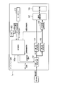
- FIG. 1 is a block diagram showing a configuration of a display device 1 according to the first embodiment of the present invention.
- the display device 1 includes a signal level detection circuit 101 (signal level detection unit), a control circuit 102 (control unit), a memory 103, a first color conversion circuit 104 (first image correction unit), A dichroic conversion circuit 105 (second image correction unit), an H / V (horizontal / vertical) position control circuit 106 (extraction unit), an image superimposing circuit 107 (image superimposing unit), and a display unit 108 are configured.
- a signal level detection circuit 101 signal level detection unit
- control circuit 102 control unit
- a memory 103 a first color conversion circuit 104 (first image correction unit)
- a dichroic conversion circuit 105 second image correction unit
- H / V horizontal / vertical
- position control circuit 106 extraction unit
- an image superimposing circuit 107 image superimposing unit
- a display unit 108 are configured.
- the signal level detection circuit 101 detects the RGB (red, green, blue) signal levels of the image signal input from the signal source, and outputs the detected signal levels to the control circuit 102 based on the RGB level signals. Further, the signal level detection circuit 101 outputs the image signal input from the signal source to the first color conversion circuit 104 and the second color conversion circuit 105 so that separate color conversion outputs can be obtained.
- RGB red, green, blue
- the control circuit 102 is an MPU (Micro-Processing Unit) and can access the memory 103.
- the control circuit 102 outputs to the signal level detection circuit 101 a position designation signal that indicates the measurement position of the signal level.
- the control circuit 102 detects a monochrome region based on the RGB color signal levels indicated by the RGB level signals input from the signal level detection circuit 101 in response to the position designation signal. Further, the control circuit 102 instructs the first color conversion circuit 104 to perform image correction to be applied to the entire image (color image) with the image control signal, and performs image correction to be applied to the monochrome image with the second color using the image control signal.
- the conversion circuit 105 is instructed. Further, the control circuit 102 outputs a position control signal indicating the position of the detected monochrome area to the H / V position control circuit 106.
- the memory 103 stores a determination level threshold, a gamma correction coefficient to be applied to the entire image (color image), and a gamma correction coefficient to be applied to a monochrome image.
- the determination level threshold indicates a color difference used for determining whether or not two pixels have the same color.
- the first color conversion circuit 104 performs image correction on the image signal input from the signal level detection circuit 101 according to the image control signal input from the control circuit 102, and outputs the image correction circuit 107 to the image superimposition circuit 107.
- the second color conversion circuit 105 performs image correction on the image signal in accordance with the image control signal from the control circuit 102 on the image signal input from the signal level detection circuit 101, and outputs the image signal to the H / V position control circuit 106.
- the H / V position control circuit 106 extracts a monochrome region image signal from the image signal input from the second color conversion circuit 105 according to the position indicated by the position control signal input from the control circuit 102, and the image superimposing circuit 107. Output to. As a result, only a part of the input image is input to the image superimposing circuit 107 through the H / V position control circuit 106.
- the image superimposing circuit 107 superimposes the image signal output from the first color conversion circuit 104 and the image signal output from the H / V position control circuit 106 and outputs them to the display unit 108.
- the display unit 108 is a display panel such as an LCD (Liquid Crystal Display), and displays the image signal superimposed by the image superimposing circuit 107.
- the pixel position in the horizontal direction of the image signal is xn (n is a positive number less than N), and the pixel position in the vertical direction is ym (m is a positive number less than M). Further, the red signal level of coordinates (xn, ym) is Rnm, the blue signal level is Bnm, and the green signal level is Gnm.
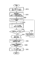
- FIG. 2 is a diagram illustrating a processing flow of the display device 1.
- the user turns on the display device 1.
- the control circuit 102 instructs the signal level detection circuit 101 to acquire a monochrome area range (step S110).
- the control circuit 102 first determines the coordinates (x1, y1) as sampling points (measurement positions).
- the control circuit 102 outputs a position designation signal that instructs acquisition of the signal level of the determined sampling point to the signal level detection circuit 101.
- the signal level detection circuit 101 detects the signal level of each RGB color at the sampling point designated by the position designation signal, and outputs the RGB level signal in which these detected signal levels are set to the control circuit 102 (step S115).
- the control circuit 102 acquires a red signal level R11, a green signal level G11, and a blue signal level B11 from the RGB signal levels.
- the control circuit 102 calculates signal level ratios [R11 / (R11 + G11 + B11), G11 / (R11 + G11 + B11), B11 / (R11 + G11 + B11)] with respect to the entire RGB colors (step S120). Since the control circuit 102 has not yet acquired the signal level of the adjacent sampling point, the monochrome determination is not performed and the process of step S125 is performed.
- the control circuit 102 determines that the coordinates (x1, x1) of the current sampling point are not the maximum coordinates (xN, yM) (step S125: NO), and moves the coordinates of the sampling point to (x2, y1). (Step S130).
- the control circuit 102 outputs a position designation signal for instructing acquisition of the signal level of the sampling point after movement to the signal level detection circuit 101.
- the signal level detection circuit 101 detects the signal level of each RGB color at the sampling point designated by the position designation signal, and outputs the RGB level signal in which these detected signal levels are set to the control circuit 102 (step S115).
- the control circuit 102 acquires a red signal level R21, a green signal level G21, and a blue signal level B21 from the RGB signal levels.
- the control circuit 102 calculates signal level ratios [R21 / (R21 + G21 + B21), G21 / (R21 + G21 + B21), B21 / (R21 + G21 + B21)] with respect to the entire RGB colors.
- control circuit 102 compares the difference between the sampling points adjacent to the coordinates (x1, y1) and the coordinates (x2, y1) with respect to the entire RGB colors [R21 / (R21 + G21 + B21) ⁇ R11 / (R11 + G11 + B11), G21. / (R21 + G21 + B21) ⁇ G11 / (R11 + G11 + B11), B21 / (R21 + G21 + B21) ⁇ B11 / (R11 + G11 + B11)] is calculated.
- the control circuit 102 determines that the sampling points of the coordinates (x1, y1) and the coordinates (x2, y1) are “identical” when the calculated difference in the ratio of each color to the whole color is 0 or less than the determination level threshold value read from the memory 103. On the other hand, if it exceeds the range, it is determined as “non-identical color”.
- the control circuit 102 associates the coordinates of the sampling points with the discrimination results and primarily stores them in the memory 103 (step S120).
- control circuit 102 and the signal level detection circuit 101 repeat the series of operations from step S115 to step S130 until the sampling point reaches the maximum coordinate (xN, yM).
- control circuit 102 determines that the coordinates of the sampling point have reached the maximum coordinates (step S125: YES)
- the control circuit 102 reads the coordinates of the sampling points stored as the same color in the memory 103, and these coordinates are read out.
- the largest rectangular area included is detected as a monochrome area (step S135).
- the control circuit 102 reads out a gamma correction coefficient to be applied to the entire image from the memory 103, and instructs the first color conversion circuit 104 with the read gamma correction coefficient with an image control signal. Further, the control circuit 102 reads out the gamma correction coefficient to be applied to the monochrome image from the memory 103 and instructs the second color conversion circuit 105 with the read gamma correction coefficient with an image control signal. The control circuit 102 outputs a position control signal indicating the position of the monochrome area detected in step S135 to the H / V position control circuit 106.
- the signal level detection circuit 101 outputs the image signal to the first color conversion circuit 104 and the second color conversion circuit 105.
- the first color conversion circuit 104 corrects the color of the image indicated by the image signal input from the signal level detection circuit 101 with the gamma correction coefficient for the entire image specified by the image control signal, and outputs the image color to the image superimposing circuit 107.
- the second color conversion circuit 105 corrects the color of the image indicated by the image signal input from the signal level detection circuit 101 with a gamma correction coefficient for a monochrome image specified by the image control signal, and an H / V position control circuit. It outputs to 106 (step S140).
- the H / V position control circuit 106 extracts a monochrome region image signal from the image signal input from the second color conversion circuit 105 according to the position indicated by the position control signal input from the control circuit 102, and the image superimposing circuit 107. Output to.
- the image superimposing circuit 107 superimposes the monochrome region image signal input from the H / V position control circuit 106 on the image signal input from the first color conversion circuit 104 and outputs the image signal to the display unit 108.
- the display unit 108 displays the image superimposed by the image superimposing circuit 107 (step S145).
- step S150 signal input continued
- the control circuit 102 sets the initial value of the sampling point as coordinates (x1, y1) and repeats the processing from step S115.
- step S150 signal cut or power cut
- the control circuit 102 ends the processing.
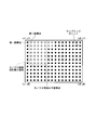
- FIG. 3 is a diagram illustrating an example of determination of a monochrome area by the control circuit 102.
- sampling points determined to be the same color as adjacent sampling points are indicated by black circles, and sampling points determined not to be the same color are indicated by white circles.
- the control circuit 102 of the display device 1 determines the first coordinate point that is the sampling point for measuring the RGB signal level in the screen, and determines the RGB signal level of the first coordinate point.
- the monochrome image region is detected by sequentially comparing the RGB signal levels of the second coordinate point, which is a sampling point around the first coordinate point.
- the control circuit 102 In order to detect a rectangular monochrome area, the control circuit 102 first determines, for example, the upper left coordinate (x1, y1) as a first coordinate point, and a peripheral position of the first coordinate point, for example, one of the first coordinate points.
- the right coordinate (x2, y1) is defined as the second coordinate point.
- the control circuit 102 calculates the difference in the ratio of these adjacent sampling points to the entire RGB colors. When the calculation result is within a predetermined range, that is, within the determination level threshold value, the control circuit 102 determines that the data of the second coordinate point is “same color” as the data of the first coordinate point, and conversely, the threshold value. In the case of exceeding, the color is discriminated as “non-identical color” and is temporarily stored in the memory 103.
- the control circuit 102 repeats such an operation until it reaches the entire screen, and as shown in the figure, detects the rectangular maximum area including the sampling point determined as “same color” as a monochrome area.
- the control circuit 102 outputs a control signal instructing the position of the monochrome area to the H / V position control circuit 106 so that the image after special processing is displayed in the determined area.
- the image superimposing circuit 107 superimposes the monochrome area in which the image correction for the monochrome image has been performed by the second color conversion circuit 105 on the image that has been subjected to the image correction for the color image by the first color conversion circuit 104. To display.
- the display device 1 since the display device 1 automatically detects a monochrome area, the gamma characteristic important for displaying an X-ray image can be displayed in an appropriate state even if the user does not specify a special area. Can be displayed. This is because the display device 1 can correctly acquire a monochrome display area by detecting pixels that do not have color information and each color has a constant ratio by the level detection process and the color difference range detection process, and only the gamma can be acquired in that area. This is because the correction coefficient can be changed to a predetermined one. In the present embodiment, the display device 1 acquires the RGB signal level of the input image signal whenever the power is turned on. Therefore, as long as there is no change in the input state of the video signal, the display device 1 automatically follows the position for performing color conversion for the monochrome image even if the position or size of the monochrome image changes depending on the user or application. Can be moved.
- FIG. 4 is a block diagram showing the configuration of the display device 1a according to the second embodiment of the present invention.
- the display device 1a shown in the figure is different from the display device 1 of the first embodiment shown in FIG. 1 in that it further includes a key button 110 and a control circuit 102a instead of the control circuit 102. is there.
- the key button 110 receives an input of a transition instruction to monochrome detection mode or an end instruction by a user of the display apparatus, and outputs a mode transition signal to the control circuit 102.
- the control circuit 102a performs the same processing as the control circuit 102 of the first embodiment when a mode transition signal for instructing transition to the monochrome detection mode is input from the key button 110.
- FIG. 5 is a diagram showing a processing flow of the display device 1a.
- the user turns on the power of the display device 1a.
- the display device 1a displays an image in the normal mode.
- the signal level detection circuit 101 outputs the image signal to the first color conversion circuit 104, and the first color conversion circuit 104 corrects the color of the image indicated by the image signal with the gamma correction coefficient for the entire image.
- the image superimposing circuit 107 causes the display unit 108 to display the image signal input from the first color conversion circuit 104 as it is.
- the user operates the key button 110 to input an instruction to shift to the monochrome detection mode.
- the key button 110 outputs a mode transition signal for instructing transition to the monochrome detection mode to the control circuit 102a.
- the control circuit 102a Upon receiving the mode transition instruction, the control circuit 102a outputs a signal level acquisition command to the signal level detection circuit 101 in order to acquire a black and white image region (step S210).
- the display device 1a performs the same processing as steps S115 to S145 in FIG. 2 (steps S215 to S250). However, the process of the control circuit 102 in the first embodiment is executed by the control circuit 102a. When the process of step S250 is completed, the control circuit 102a returns the display device 1a to the normal mode (step S255).
- the user of the display device 1a performs power-on and image signal input, and outputs a signal for shifting to a mode for determining a monochrome image by the key button 110 to the control circuit 102a.
- the control circuit 102a outputs a command to the signal level detection circuit 101 so as to acquire the range of the monochrome area.
- the display device 1a performs a process of determining whether or not the image is monochrome by calculating a difference in the ratio of each of the RGB colors to the entire color, as in the first embodiment (coordinates (x1, y1)). To (xN, yN), and the converted image subjected to the image correction for the monochrome image is superimposed on the original image and displayed on the display.
- the display device 1a returns from the monochrome detection mode to the normal mode after the monochrome image area is determined. Therefore, although it cannot follow changes in the position and size of a monochrome image, the processing from signal level acquisition to monochrome determination calculation and position determination can be performed by N ⁇ M iterations, which is the number of sampling points. The operation burden on the circuit 102a can be reduced.
- control circuit 102 shown in FIG. 1 and the control circuit 102a shown in FIG. 2 load and execute a program for realizing the processing described above from the memory in the MPU. To realize its function.
- the program may be transmitted from a computer system storing the program in a storage device or the like to another computer system via a transmission medium or by a transmission wave in the transmission medium.
- the “transmission medium” for transmitting the program refers to a medium having a function of transmitting information, such as a network (communication network) such as the Internet or a communication line (communication line) such as a telephone line.
- the program may be for realizing a part of the functions described above. Furthermore, what can implement
- the signal level detection part which detects the signal level of the primary color of each pixel from an image signal, and the signal level of the said primary color which the said signal level detection part detected about each pixel
- a control unit for detecting an area where a single color is used, a first image correction unit for performing image correction on the image signal, and the first image correction unit for the image signal.
- a second image correction unit that performs image correction, an extraction unit that extracts an image signal of the region detected by the control unit from the image signal corrected by the second image correction unit, and the first image correction unit.
- An image superimposing unit that superimposes the image signal extracted by the extracting unit on the image signal subjected to image correction, and causes the display unit to display the superimposed image signal.
- the said control part detects the pixel with which the signal level of all the primary colors is the same as a pixel in which the shade of the said single color is used, and the rectangular area containing the detected said pixel is the shade of the said single color
- the said control part detects the said area
- the display device according to any one of appendix 1 to appendix 3.
- the image display method which a display apparatus performs, Comprising: The signal level detection process which detects the signal level of the primary color of each pixel from an image signal, The signal of the said primary color detected about each pixel in the said signal level detection process Based on the level, a detection process for detecting a region where a single color shading is used, a first image correction process for performing image correction on the image signal, and the first image correction for the image signal A second image correction process for performing image correction different from the process; an extraction process for extracting an image signal of the region detected in the detection process from the image signal that has been image corrected in the second image correction process; The image signal extracted in the extraction process is superimposed on the image signal corrected in the first image correction process, and the superimposed image signal is displayed.
- the image display method characterized by comprising the image superimposing process that, the.
Landscapes
- Engineering & Computer Science (AREA)
- Physics & Mathematics (AREA)
- Computer Hardware Design (AREA)
- General Physics & Mathematics (AREA)
- Theoretical Computer Science (AREA)
- Controls And Circuits For Display Device (AREA)
Abstract
ディスプレイ装置(1)の信号レベル検出回路(101)は、画像信号から各画素のRGBの信号レベルを検出し、制御回路(102)は、信号レベル検出回路(101)が検出した各画素のRGBの信号レベルに基づいて単一色の濃淡が使用されている領域を検出する。第一色変換回路(104)は、画像信号に画像補正を行い、第二色変換回路(105)は、画像信号に第一色変換回路(104)とは異なる画像補正を行う。H/V位置制御回路(106)は、第二色変換回路(105)が画像補正を行なった画像信号から、制御回路(102)が検出した領域の画像信号を抽出する。画像重畳回路(107)は、第一色変換回路(104)が画像補正した画像信号に、H/V位置制御回路(106)が抽出した画像信号を重畳し、重畳した画像信号を表示部(108)に表示させる。
Description
本発明は、ディスプレイ装置、及び画像表示方法に関する。
レントゲンを始めとする医用画像は撮像上、白黒などの無彩色、又は単一有彩色の濃淡で表現される。このような医用画像のディスプレイへの入力階調に対する表示特性は、DICOM(Digital Imaging and COmmunication in Medicine)で規定されている。DICOMは、IT(Information Technology;情報技術)用の画像特性とは異なり、医用画像管理システム(PACS)のアプリケーションを利用して信号を出力する。ディスプレイ側には正確な階調対輝度特性が要求され、細部の調整を行った専用ディスプレイが必要とされている。しかし最近では、単一有彩色の濃淡に色付けを行って診断の支援を行うアプリケーションを扱ったり、医用機器以外の画像、例えばデジタルカメラで撮影された外傷状態を並べて診断の参考にすることが増えている。これら特性の異なる画像を同時に扱うことから、PACSアプリケーションを操作するディスプレイをカラーとし、医用画像は表示特性の異なる白黒ディスプレイに信号を送出するなど、今までは複数のディスプレイを使い分けて正しい表示特性を得ていた。
また、例えば特許文献1には、制御信号または画像信号に埋め込まれたマーカー信号に基づいて画像信号を複数の領域に分け、輪郭補正、輝度補正、ガンマ補正、カラー補正などの異なる画像処理を領域ごとに施すことが記載されている。
また、例えば特許文献1には、制御信号または画像信号に埋め込まれたマーカー信号に基づいて画像信号を複数の領域に分け、輪郭補正、輝度補正、ガンマ補正、カラー補正などの異なる画像処理を領域ごとに施すことが記載されている。
上述したように、アプリケーション操作用と医用画像表示用のディスプレイを別々に2台設置した場合、利用者は表示特性が異なる複数のディスプレイを扱うために視点移動が大きくなり、視認性が悪くなるという問題があった。
一方、昨今の大画面化、高解像度化により、1台で別々の表示特性を持たせることができるディスプレイも開発されている。これを用いれば視認性は改善されるが、ディスプレイ全体の表示特性を正確な白黒表示にするとアプリケーションの操作性が失われてしまい、ディスプレイ全体の表示特性をカラーに合わせると医用画像の正確な表示特性が得られない。また、ある領域だけを医用画像にして別々の表示特性を得ようとした場合には領域指定が煩雑になる問題があった。
このような煩雑さを解消するために、PACSアプリケーション側に医用画像の領域指定機能を持たせることが容易に考えられる。しかし、領域指定を画像信号以外の信号で伝達しなければならないため、ホストPC(パーソナルコンピュータ)、アプリケーション、ディスプレイを揃えて運用することが必要となり、汎用性に乏しいという問題があった。
上述したように、アプリケーション画像と医用画像を同時に表示させる場合、アプリケーション操作用と医用画像表示用のディスプレイを別々に設置するか、画像信号とは別の通信手段で画像上の医用画像の位置をディスプレイ側に読み込ませて1台のディスプレイに表示していた。これらいずれの場合も、アプリケーションとディスプレイとの組み合わせが発生し、且つこれらの間に通信手段を設けなければならないなど、多くの制約があった。特許文献1の技術でも、制御信号やマーカー信号などにより領域指定を行わなければならず、これらの問題を解決するものではない。
本発明は、このような事情を考慮してなされたものであり、使用者あるいはアプリケーションによる位置指定を必要とせず、異なる表示特性の領域を含んだ画像を1台で表示するディスプレイ装置、及び画像表示方法を提供する。
[1] 本発明の一態様は、画像を表示する表示部と、画像信号から各画素の原色の信号レベルを検出する信号レベル検出部と、前記信号レベル検出部が各画素について検出した前記原色の信号レベルに基づいて、単一色の濃淡が使用されている領域を検出する制御部と、前記画像信号に対して画像補正を行う第一画像補正部と、前記画像信号に対して前記第一画像補正部とは異なる画像補正を行う第二画像補正部と、前記第二画像補正部が補正した前記画像信号から前記制御部により検出された前記領域の画像信号を抽出する抽出部と、前記第一画像補正部が画像補正した前記画像信号に、前記抽出部が抽出した前記画像信号を重畳し、重畳した画像信号を前記表示部に表示させる画像重畳部と、を備えることを特徴とするディスプレイ装置である。
[2] また、本発明の一態様は、ディスプレイ装置が実行する画像表示方法であって、画像信号から各画素の原色の信号レベルを検出する信号レベル検出過程と、前記信号レベル検出過程において各画素について検出した前記原色の信号レベルに基づいて、単一色の濃淡が使用されている領域を検出する検出過程と、前記画像信号に対して画像補正を行う第一画像補正過程と、前記画像信号に対して前記第一画像補正過程とは異なる画像補正を行う第二画像補正過程と、前記第二画像補正過程において画像補正された前記画像信号から前記検出過程において検出された前記領域の画像信号を抽出する抽出過程と、前記第一画像補正過程において画像補正された前記画像信号に、前記抽出過程において抽出された前記画像信号を重畳し、重畳した画像信号を表示させる画像重畳過程と、を有することを特徴とする画像表示方法である。
本発明によれば、使用者あるいはアプリケーションによる位置指定を必要とせず、異なる表示特性の領域を含んだ画像を1台のディスプレイ装置に表示させることができる。
以下、本発明の実施形態を、図面を参照して説明する。
レントゲンを始めとする医用画像は、モノクローム(白黒または特定色の濃淡。以下、「モノクロ」と記載する。)で表現され、ディスプレイへの入力階調に対する医用画像の表示特性は、DICOM(Digital Imaging and COmmunication in Medicine)で規定されている。しかし、医用画像の縦横のサイズは様々であり、またそれらを操作するアプリケーション画像の部分がモノクロ表示になると視認性や操作性が失われて扱いにくい。そこで、本実施形態では、一つの入力信号に対して複数の色変換や画像変換を同時に行うことが可能なディスプレイ装置において、カラー画像信号に含まれているモノクロ領域を検出し、その検出した領域だけにモノクロ画像用の特別な画像補正を行った後、元の信号に重畳して表示する。これにより、モノクロ領域における正確な階調表示と、アプリケーションの操作性や視認性の維持とを両立することが可能になる。
[第1の実施形態]
図1は、本発明の第1の実施形態によるディスプレイ装置1の構成を示すブロック図である。同図に示すように、ディスプレイ装置1は、信号レベル検出回路101(信号レベル検出部)、制御回路102(制御部)、メモリ103、第一色変換回路104(第一画像補正部)、第二色変換回路105(第二画像補正部)、H/V(水平/垂直)位置制御回路106(抽出部)、画像重畳回路107(画像重畳部)、及び表示部108を備えて構成される。
図1は、本発明の第1の実施形態によるディスプレイ装置1の構成を示すブロック図である。同図に示すように、ディスプレイ装置1は、信号レベル検出回路101(信号レベル検出部)、制御回路102(制御部)、メモリ103、第一色変換回路104(第一画像補正部)、第二色変換回路105(第二画像補正部)、H/V(水平/垂直)位置制御回路106(抽出部)、画像重畳回路107(画像重畳部)、及び表示部108を備えて構成される。
信号レベル検出回路101は、信号源から入力された画像信号のRGB(赤、緑、青)の信号レベルを検知し、検出したこれらの信号レベルをRGBレベル信号により制御回路102に出力する。さらに、信号レベル検出回路101は、別々の色変換出力が得られるように、信号源から入力された画像信号を第一色変換回路104及び第二色変換回路105に出力する。
制御回路102は、MPU(Micro-Processing Unit)であり、メモリ103にアクセス可能である。制御回路102は、信号レベル検出回路101に信号レベルの計測位置を指示する位置指定信号を出力する。制御回路102は、この位置指定信号に対応して信号レベル検出回路101から入力されたRGBレベル信号が示すRGB各色の信号レベルに基づいて、モノクロ領域を検出する。また、制御回路102は、画像全体(カラー画像)に適用すべき画像補正を画像制御信号で第一色変換回路104に指示し、モノクロ画像に適用すべき画像補正を画像制御信号で第二色変換回路105に指示する。さらに、制御回路102は、検出したモノクロ領域の位置を示す位置制御信号をH/V位置制御回路106に出力する。
メモリ103は、判定レベル閾値と、画像全体(カラー画像)に適用すべきガンマ補正係数、及びモノクロ画像に適用すべきガンマ補正係数を記憶する。判定レベル閾値は、2つの画素が同一色であるか否かの判断に用いられる色差を示す。
第一色変換回路104は、信号レベル検出回路101から入力された画像信号に、制御回路102から入力された画像制御信号に従って画像補正を行ない、画像重畳回路107に出力する。第二色変換回路105は、信号レベル検出回路101から入力された画像信号に、制御回路102からの画像制御信号に従って画像信号に画像補正を行ない、H/V位置制御回路106に出力する。
H/V位置制御回路106は、第二色変換回路105から入力された画像信号から、制御回路102から入力された位置制御信号が示す位置に従ってモノクロ領域の画像信号を抽出し、画像重畳回路107に出力する。これにより、入力画像の一部のみがH/V位置制御回路106を通して画像重畳回路107に入力される。
画像重畳回路107は、第一色変換回路104から出力された画像信号と、H/V位置制御回路106から出力された画像信号とを重畳して表示部108に出力する。表示部108は、LCD(Liquid Crystal Display)などの表示パネルであり、画像重畳回路107により重畳された画像信号を表示する。
次に、ディスプレイ装置1の動作について説明する。なお、画像信号の水平方向の画素位置をxn(nはN以下の正数)、垂直方向の画素位置をym(mはM以下の正数)とする。また、座標(xn,ym)の赤色の信号レベルをRnm、青色の信号レベルをBnm、緑色の信号レベルをGnmとする。
図2は、ディスプレイ装置1の処理フローを示す図である。
まず、使用者は、ディスプレイ装置1の電源を投入する。電源投入後、信号源から信号レベル検出回路101に画像信号が入力されると、制御回路102は、モノクロ領域の範囲を取得するよう信号レベル検出回路101に命令する(ステップS110)。
まず、使用者は、ディスプレイ装置1の電源を投入する。電源投入後、信号源から信号レベル検出回路101に画像信号が入力されると、制御回路102は、モノクロ領域の範囲を取得するよう信号レベル検出回路101に命令する(ステップS110)。
制御回路102は、最初に座標(x1,y1)をサンプリングポイント(測定位置)として決定する。制御回路102は、決定したサンプリングポイントの信号レベルの取得を命令する位置指定信号を、信号レベル検出回路101に出力する。信号レベル検出回路101は、位置指定信号により指定されたサンプリングポイントのRGB各色の信号レベルを検出し、検出したこれら信号レベルを設定したRGBレベル信号を制御回路102に出力する(ステップS115)。
制御回路102は、RGB信号レベルから赤色の信号レベルR11、緑の信号レベルG11、青の信号レベルB11を取得する。制御回路102は、RGB各色の色全体に対する信号レベルの比[R11/(R11+G11+B11),G11/(R11+G11+B11),B11/(R11+G11+B11)]を計算する(ステップS120)。制御回路102は、隣接するサンプリングポイントの信号レベルをまだ取得していないため、モノクロ判定は行わず、ステップS125の処理を行う。
制御回路102は、現在のサンプリングポイントの座標(x1,x1)が最大の座標(xN,yM)ではないと判断し(ステップS125:NO)、サンプリングポイントの座標を(x2,y1)に移動させる(ステップS130)。
制御回路102は、移動後のサンプリングポイントの信号レベルの取得を命令する位置指定信号を、信号レベル検出回路101に出力する。信号レベル検出回路101は、位置指定信号により指定されたサンプリングポイントのRGB各色の信号レベルを検出し、検出したこれら信号レベルを設定したRGBレベル信号を制御回路102に出力する(ステップS115)。
制御回路102は、RGB信号レベルから赤色の信号レベルR21、緑の信号レベルG21、青の信号レベルB21を取得する。制御回路102は、RGB各色の色全体に対する信号レベルの比[R21/(R21+G21+B21),G21/(R21+G21+B21),B21/(R21+G21+B21)]を計算する。
さらに、制御回路102は、座標(x1,y1)及び座標(x2,y1)の隣接するサンプリングポイントについて、RGB各色の色全体に対する比の差[R21/(R21+G21+B21)-R11/(R11+G11+B11),G21/(R21+G21+B21)-G11/(R11+G11+B11),B21/(R21+G21+B21)-B11/(R11+G11+B11)]を計算する。制御回路102は、計算した各色の色全体に対する比の差が0またはメモリ103から読み出した判定レベル閾値以下の場合、座標(x1,y1)と座標(x2,y1)の両サンプリングポイントが「同一色」と判別し、反対にその範囲を超える場合「非同一色」と判別する。制御回路102は、サンプリングポイントの座標と判別結果とを対応付けてメモリ103に一次記憶する(ステップS120)。
制御回路102は、現在のサンプリングポイントの座標(xn,ym)が最大の座標(xN、yM)ではないと判断し(ステップS125:NO)、サンプリングポイントの座標を移動させ(ステップS130)、ステップS115からの処理を繰り返す。例えば、ステップS130において、制御回路102は、i<Nであれば、座標(x(i+n),ym)を新たなサンプリングポイントとし、i=Nであれば、座標(x1,y(m+1))を新たなサンプリングポイントとする。
制御回路102及び信号レベル検出回路101は、ステップS115からステップS130の一連の動作を、サンプリングポイントが最大の座標(xN、yM)に達するまで繰り返す。
制御回路102は、サンプリングポイントの座標が最大の座標に達したと判断した場合(ステップS125:YES)、メモリ103に同一色として記憶されているサンプリングポイントの座標を読み出し、読み出したそれらの座標が含まれる最大の矩形領域をモノクロ領域として検出する(ステップS135)。
制御回路102は、画像全体に適用すべきガンマ補正係数をメモリ103から読み出し、この読み出したガンマ補正係数を画像制御信号で第一色変換回路104に指示する。さらに、制御回路102は、モノクロ画像に適用すべきガンマ補正係数をメモリ103から読み出し、この読み出したガンマ補正係数を画像制御信号で第二色変換回路105に指示する。制御回路102は、ステップS135において検出したモノクロ領域の位置を示す位置制御信号をH/V位置制御回路106に出力する。
信号レベル検出回路101は、画像信号を第一色変換回路104及び第二色変換回路105に出力する。第一色変換回路104は、信号レベル検出回路101から入力された画像信号が示す画像の色を、画像制御信号で指定された画像全体用のガンマ補正係数により補正し、画像重畳回路107に出力する。第二色変換回路105は、信号レベル検出回路101から入力された画像信号が示す画像の色を、画像制御信号で指定されたモノクロ画像用のガンマ補正係数により補正し、H/V位置制御回路106に出力する(ステップS140)。
H/V位置制御回路106は、制御回路102から入力された位置制御信号が示す位置に従って、第二色変換回路105から入力された画像信号からモノクロ領域の画像信号を抽出し、画像重畳回路107に出力する。画像重畳回路107は、第一色変換回路104から入力された画像信号に、H/V位置制御回路106から入力されたモノクロ領域の画像信号を重畳して表示部108に出力する。表示部108は、画像重畳回路107により重畳された画像を表示する(ステップS145)。
信号源からの画像信号入力が継続される場合(ステップS150:信号入力継続)、制御回路102は、サンプリングポイントの初期値を座標(x1,y1)とし、ステップS115からの処理を繰り返す。一方、信号源からの画像信号の入力が途絶えた、あるいはディスプレイ装置1の電源が切断された場合(ステップS150:信号断又は電源断)、制御回路102は、処理を終了する。
図3は、制御回路102によるモノクロ領域の判断例を示す図である。同図では、隣接するサンプリングポイントと同一色と判断されたサンプリングポイントを黒丸により、同一色ではないと判断されたサンプリングポイントを白丸により示している。
上述したように、本実施形態のディスプレイ装置1の制御回路102は、画面内でRGB信号レベルを測定する対象のサンプリングポイントである第一座標点を決め、第一座標点のRGBの信号レベルを、第一座標点の周辺のサンプリングポイントである第二座標点のRGBの信号レベルと順次比較して、モノクロ画像の領域を検出する。
制御回路102は、矩形のモノクロ領域を検出するために、まず例えば左上の座標(x1,y1)を第一座標点と定め、第一座標点の周辺位置、例えば、第一座標点の1つ右側の座標(x2,y1)を第二座標点と定める。制御回路102は、これら隣接するサンプリングポイントのRGB各色の色全体に対する比の差を計算する。制御回路102は、計算結果が予め決めておいた範囲、即ち判定レベル閾値内の場合、第二座標点のデータは、第一座標点のデータと「同一色」と判別し、反対にその閾値を超える場合には「非同一色」として判別し、メモリ103に一次記憶する。
制御回路102は、このような動作を画面全域に至るまで繰り返し、同図に示すように、「同一色」と判別されたサンプリングポイントが含まれる矩形最大領域を、モノクロ領域として検出する。制御回路102は、決定した領域には特別加工した後の画像が表示されるように、H/V位置制御回路106にモノクロ領域の位置を指示する制御信号を出力する。これにより、画像重畳回路107は、第一色変換回路104によってカラー画像用の画像補正を行った画像に、第二色変換回路105によってモノクロ画像用の画像補正が行われたモノクロ領域を重畳させ、表示させる。
上述した実施形態によれば、ディスプレイ装置1は、自動的にモノクロ領域を検出するため、使用者が特別な領域指定をせずとも、レントゲン画像を表示する際に重要なガンマ特性を適切な状態で表示することができる。これは、ディスプレイ装置1が、レベル検出処理および色差範囲の検出処理により、色情報を持たず、各色が一定比率である画素を検出することによって、モノクロ表示領域が正しく取得でき、その領域のみガンマ補正係数を予め指定したものに変更できるようにしたためである。また、本実施形態では、ディスプレイ装置1は、電源が投入されている間は常に、入力される画像信号のRGBの信号レベルを取得する。従って、ディスプレイ装置1は、映像信号の入力状態に変化が無い限り、使用者やアプリケーションによってモノクロ画像の位置やサイズが変わっても、自動的に追従してモノクロ画像用の色変換を行う位置を移動させることができる。
[第2の実施形態]
図4は、本発明の第2の実施形態によるディスプレイ装置1aの構成を示すブロック図である。同図に示すディスプレイ装置1aが、図1に示す第1の実施形態のディスプレイ装置1と異なる点は、キーボタン110をさらに備える点、及び、制御回路102に代えて制御回路102aを備える点である。
図4は、本発明の第2の実施形態によるディスプレイ装置1aの構成を示すブロック図である。同図に示すディスプレイ装置1aが、図1に示す第1の実施形態のディスプレイ装置1と異なる点は、キーボタン110をさらに備える点、及び、制御回路102に代えて制御回路102aを備える点である。
キーボタン110は、ディスプレイ装置の使用者によるモノクロ検出モードへの移行指示あるいは終了指示の入力を受け、モード移行信号を制御回路102に出力する。制御回路102aは、モノクロ検出モードへの移行を指示するモード移行信号がキーボタン110から入力された場合に、第1の実施形態の制御回路102と同様の処理を行う。
図5は、ディスプレイ装置1aの処理フローを示す図である。
まず、使用者は、ディスプレイ装置1aの電源を投入する。電源投入後、信号源から信号レベル検出回路101に画像信号が入力されると、ディスプレイ装置1aは、通常モードにより映像を表示する。通常モードの場合、信号レベル検出回路101は、画像信号を第一色変換回路104に出力し、第一色変換回路104は、画像信号が示す画像の色を画像全体用のガンマ補正係数により補正し、画像重畳回路107に出力する。画像重畳回路107は、第一色変換回路104から入力された画像信号をそのまま表示部108に表示させる。
まず、使用者は、ディスプレイ装置1aの電源を投入する。電源投入後、信号源から信号レベル検出回路101に画像信号が入力されると、ディスプレイ装置1aは、通常モードにより映像を表示する。通常モードの場合、信号レベル検出回路101は、画像信号を第一色変換回路104に出力し、第一色変換回路104は、画像信号が示す画像の色を画像全体用のガンマ補正係数により補正し、画像重畳回路107に出力する。画像重畳回路107は、第一色変換回路104から入力された画像信号をそのまま表示部108に表示させる。
使用者は、キーボタン110を操作してモノクロ検出モードへの移行指示を入力する。キーボタン110は、モノクロ検出モードへの移行を指示するモード移行信号を制御回路102aに出力する。制御回路102aは、モード移行指示を受信すると、白黒の画像領域を取得するため信号レベルの取得命令を信号レベル検出回路101に出力する(ステップS210)。ディスプレイ装置1aは、図2のステップS115~S145と同様の処理を行う(ステップS215~S250)。ただし、第1の実施形態における制御回路102の処理は、制御回路102aが実行する。ステップS250の処理を終了すると、制御回路102aは、ディスプレイ装置1aを通常モードへ戻す(ステップS255)。
上述したように、本実施形態では、ディスプレイ装置1aの使用者が電源投入と画像信号入力を行い、キーボタン110によりモノクロ画像を判別するモードに移行する信号を制御回路102aに出力する。これに応じて、制御回路102aが、モノクロ領域の範囲を取得するよう信号レベル検出回路101に命令を出力する。この命令の出力後、ディスプレイ装置1aは、第1の実施形態と同様に、RGB各色の色全体に対する比の差を計算してモノクロであるか否かを判定する処理を座標(x1,y1)から(xN,yN)まで実行し、モノクロ画像用の画像補正を行った変換画像を、元の画像に重畳してディスプレイに表示させる。
本実施形態では、第1の実施形態のように、信号入力の状態変化を監視して判別するプロセスが無く、ディスプレイ装置1aは、モノクロ画像領域の確定後、モノクロ検出モードから通常モードに戻る。従って、モノクロ画像の位置やサイズの変化には追従できないが、信号レベルの取得からモノクロ判定の演算及び位置判別までの処理が、サンプリングポイント数であるN×M回の繰り返し処理で済むため、制御回路102aの動作負担を軽減することができる。
[第3の実施形態]
モノクロ画像が白の上に黒の単一色の濃淡で表した無彩色の白黒の画像である場合、以下のようにモノクロ領域を判別することができる。すなわち、図2の第1の実施形態のステップS120において、制御回路102は、サンプリングポイントである座標(xn,ym)の信号レベルがRnm=Gnm=Bnmであれば、白黒の画素であることをメモリ103に一次記憶させる。そしてステップS130において、制御回路102は、メモリ103に白黒の画素として記憶されている座標を読み出し、読み出したそれらの座標が含まれる最大の矩形領域を白黒領域(モノクロ領域)として検出する。
なお、第2の実施形態における図5のステップS225、S240における制御回路102aの処理を上記と同様の処理とし、白黒領域を判断することもできる。
モノクロ画像が白の上に黒の単一色の濃淡で表した無彩色の白黒の画像である場合、以下のようにモノクロ領域を判別することができる。すなわち、図2の第1の実施形態のステップS120において、制御回路102は、サンプリングポイントである座標(xn,ym)の信号レベルがRnm=Gnm=Bnmであれば、白黒の画素であることをメモリ103に一次記憶させる。そしてステップS130において、制御回路102は、メモリ103に白黒の画素として記憶されている座標を読み出し、読み出したそれらの座標が含まれる最大の矩形領域を白黒領域(モノクロ領域)として検出する。
なお、第2の実施形態における図5のステップS225、S240における制御回路102aの処理を上記と同様の処理とし、白黒領域を判断することもできる。
以上、本発明の実施の形態について説明したが、図1に示す制御回路102、及び図2に示す制御回路102aは、上述した処理を実現するためのプログラムをMPU内のメモリからロードして実行することによりその機能を実現させる。
また、上記プログラムは、このプログラムを記憶装置等に格納したコンピュータシステムから、伝送媒体を介して、あるいは、伝送媒体中の伝送波により他のコンピュータシステムに伝送されてもよい。ここで、プログラムを伝送する「伝送媒体」は、インターネット等のネットワーク(通信網)や電話回線等の通信回線(通信線)のように情報を伝送する機能を有する媒体のことをいう。また、上記プログラムは、前述した機能の一部を実現するためのものであっても良い。さらに、前述した機能をコンピュータシステムにすでに記録されているプログラムとの組み合わせで実現できるもの、いわゆる差分ファイル(差分プログラム)であっても良い。
上記の実施形態の一部または全部は、以下の付記のようにも記載されうるが、以下には限られない。
(付記1) 画像を表示する表示部と、画像信号から各画素の原色の信号レベルを検出する信号レベル検出部と、前記信号レベル検出部が各画素について検出した前記原色の信号レベルに基づいて、単一色の濃淡が使用されている領域を検出する制御部と、前記画像信号に対して画像補正を行う第一画像補正部と、前記画像信号に対して前記第一画像補正部とは異なる画像補正を行う第二画像補正部と、前記第二画像補正部が補正した前記画像信号から前記制御部により検出された前記領域の画像信号を抽出する抽出部と、前記第一画像補正部が画像補正した前記画像信号に、前記抽出部が抽出した前記画像信号を重畳し、重畳した画像信号を前記表示部に表示させる画像重畳部と、を備えることを特徴とするディスプレイ装置。
(付記2)前記制御部は、前記画像信号における画素と、当該画素に隣接する画素との間で、全ての原色に対する前記原色それぞれの信号レベルの比の差が所定以内である場合、前記画素と前記隣接する画素とが同一色であると判断し、同一色と判断された前記画素を含む矩形領域を前記単一色の濃淡が使用されている前記領域として検出する、ことを特徴とする付記1に記載のディスプレイ装置。
(付記3)前記制御部は、全ての原色の信号レベルが同一である画素を前記単一色の濃淡が使用されている画素として検出し、検出した前記画素を含む矩形領域を前記単一色の濃淡が使用されている前記領域として検出する、ことを特徴とする付記1に記載のディスプレイ装置。
(付記4)前記制御部は、画像信号が入力されている間、あるいは、検出モードへの移行指示が入力されたときに、一色の濃淡が使用されている前記領域を検出する、ことを特徴とする付記1から付記3のいずれかに記載のディスプレイ装置。
(付記5)ディスプレイ装置が実行する画像表示方法であって、画像信号から各画素の原色の信号レベルを検出する信号レベル検出過程と、前記信号レベル検出過程において各画素について検出した前記原色の信号レベルに基づいて、単一色の濃淡が使用されている領域を検出する検出過程と、前記画像信号に対して画像補正を行う第一画像補正過程と、前記画像信号に対して前記第一画像補正過程とは異なる画像補正を行う第二画像補正過程と、前記第二画像補正過程において画像補正された前記画像信号から前記検出過程において検出された前記領域の画像信号を抽出する抽出過程と、前記第一画像補正過程において画像補正された前記画像信号に、前記抽出過程において抽出された前記画像信号を重畳し、重畳した画像信号を表示させる画像重畳過程と、を有することを特徴とする画像表示方法。
1、1a…ディスプレイ装置
101…信号レベル検出回路
102、102a…制御回路
103…メモリ
104…第一色変換回路
105…第二色変換回路
106…H/V位置制御回路
107…画像重畳回路
108…表示部
110…キーボタン
101…信号レベル検出回路
102、102a…制御回路
103…メモリ
104…第一色変換回路
105…第二色変換回路
106…H/V位置制御回路
107…画像重畳回路
108…表示部
110…キーボタン
Claims (5)
- 画像を表示する表示部と、
画像信号から各画素の原色の信号レベルを検出する信号レベル検出部と、
前記信号レベル検出部が各画素について検出した前記原色の信号レベルに基づいて、単一色の濃淡が使用されている領域を検出する制御部と、
前記画像信号に対して画像補正を行う第一画像補正部と、
前記画像信号に対して前記第一画像補正部とは異なる画像補正を行う第二画像補正部と、
前記第二画像補正部が補正した前記画像信号から前記制御部により検出された前記領域の画像信号を抽出する抽出部と、
前記第一画像補正部が画像補正した前記画像信号に、前記抽出部が抽出した前記画像信号を重畳し、重畳した画像信号を前記表示部に表示させる画像重畳部と、
を備えることを特徴とするディスプレイ装置。 - 前記制御部は、前記画像信号における画素と、当該画素に隣接する画素との間で、全ての原色に対する前記原色それぞれの信号レベルの比の差が所定以内である場合、前記画素と前記隣接する画素とが同一色であると判断し、同一色と判断された前記画素を含む矩形領域を前記単一色の濃淡が使用されている前記領域として検出する、
ことを特徴とする請求項1に記載のディスプレイ装置。 - 前記制御部は、全ての原色の信号レベルが同一である画素を前記単一色の濃淡が使用されている画素として検出し、検出した前記画素を含む矩形領域を前記単一色の濃淡が使用されている前記領域として検出する、
ことを特徴とする請求項1に記載のディスプレイ装置。 - 前記制御部は、画像信号が入力されている間、あるいは、検出モードへの移行指示が入力されたときに、一色の濃淡が使用されている前記領域を検出する、
ことを特徴とする請求項1から請求項3のいずれか1項に記載のディスプレイ装置。 - ディスプレイ装置が実行する画像表示方法であって、
画像信号から各画素の原色の信号レベルを検出する信号レベル検出過程と、
前記信号レベル検出過程において各画素について検出した前記原色の信号レベルに基づいて、単一色の濃淡が使用されている領域を検出する検出過程と、
前記画像信号に対して画像補正を行う第一画像補正過程と、
前記画像信号に対して前記第一画像補正過程とは異なる画像補正を行う第二画像補正過程と、
前記第二画像補正過程において画像補正された前記画像信号から前記検出過程において検出された前記領域の画像信号を抽出する抽出過程と、
前記第一画像補正過程において画像補正された前記画像信号に、前記抽出過程において抽出された前記画像信号を重畳し、重畳した画像信号を表示させる画像重畳過程と、
を有することを特徴とする画像表示方法。
Priority Applications (3)
| Application Number | Priority Date | Filing Date | Title |
|---|---|---|---|
| PCT/JP2012/076910 WO2014061124A1 (ja) | 2012-10-18 | 2012-10-18 | ディスプレイ装置、及び画像表示方法 |
| CN201280076456.5A CN104737222B (zh) | 2012-10-18 | 2012-10-18 | 显示装置和图像显示方法 |
| US14/436,112 US20150262552A1 (en) | 2012-10-18 | 2012-10-18 | Display device and image display method |
Applications Claiming Priority (1)
| Application Number | Priority Date | Filing Date | Title |
|---|---|---|---|
| PCT/JP2012/076910 WO2014061124A1 (ja) | 2012-10-18 | 2012-10-18 | ディスプレイ装置、及び画像表示方法 |
Publications (1)
| Publication Number | Publication Date |
|---|---|
| WO2014061124A1 true WO2014061124A1 (ja) | 2014-04-24 |
Family
ID=50487712
Family Applications (1)
| Application Number | Title | Priority Date | Filing Date |
|---|---|---|---|
| PCT/JP2012/076910 Ceased WO2014061124A1 (ja) | 2012-10-18 | 2012-10-18 | ディスプレイ装置、及び画像表示方法 |
Country Status (3)
| Country | Link |
|---|---|
| US (1) | US20150262552A1 (ja) |
| CN (1) | CN104737222B (ja) |
| WO (1) | WO2014061124A1 (ja) |
Cited By (1)
| Publication number | Priority date | Publication date | Assignee | Title |
|---|---|---|---|---|
| CN104469351A (zh) * | 2014-12-11 | 2015-03-25 | 武汉精测电子技术股份有限公司 | 一种检测视频源产生的lvds视频信号的方法 |
Families Citing this family (1)
| Publication number | Priority date | Publication date | Assignee | Title |
|---|---|---|---|---|
| KR102453070B1 (ko) * | 2018-06-05 | 2022-10-07 | 에이조 가부시키가이샤 | 화상 처리 장치 및 화상 처리 프로그램 |
Citations (4)
| Publication number | Priority date | Publication date | Assignee | Title |
|---|---|---|---|---|
| JPH01188896A (ja) * | 1988-01-25 | 1989-07-28 | Matsushita Electric Ind Co Ltd | ビットマップ表示装置 |
| JP2010256536A (ja) * | 2009-04-23 | 2010-11-11 | Sharp Corp | 画像処理装置及び画像表示装置 |
| JP2011232382A (ja) * | 2010-04-23 | 2011-11-17 | Nanao Corp | 画像表示装置、画像領域検出方法及びコンピュータプログラム |
| JP4977255B1 (ja) * | 2011-03-31 | 2012-07-18 | 株式会社ナナオ | 表示装置、画像処理装置、画像領域検出方法、画像処理方法及びコンピュータプログラム |
Family Cites Families (19)
| Publication number | Priority date | Publication date | Assignee | Title |
|---|---|---|---|---|
| JPH11190987A (ja) * | 1997-10-20 | 1999-07-13 | Sony Corp | 表示装置、マーカー信号構成方法、マーカー信号検出回路、及び制御信号発生回路 |
| JPH11298795A (ja) * | 1998-04-14 | 1999-10-29 | Sony Corp | 制御信号発生回路 |
| JPH11327520A (ja) * | 1998-05-13 | 1999-11-26 | Sony Corp | 表示制御方法及び表示制御装置 |
| KR100512622B1 (ko) * | 2000-06-08 | 2005-09-02 | 마쯔시다덴기산교 가부시키가이샤 | 화상 표시 장치와 화상 표시 방법 |
| US7030848B2 (en) * | 2001-03-30 | 2006-04-18 | Matsushita Electric Industrial Co., Ltd. | Liquid crystal display |
| JP3863058B2 (ja) * | 2001-09-13 | 2006-12-27 | 三菱電機株式会社 | 光受信装置 |
| JP3942986B2 (ja) * | 2002-08-09 | 2007-07-11 | Necディスプレイソリューションズ株式会社 | 表示装置、表示システム及びケーブル |
| CN100378795C (zh) * | 2003-07-18 | 2008-04-02 | 明基电通股份有限公司 | 具有影像保持功能的显示装置及其影像保持方法 |
| JP2005197991A (ja) * | 2004-01-07 | 2005-07-21 | Orion Denki Kk | オンスクリーン表示装置 |
| JP4063795B2 (ja) * | 2004-06-24 | 2008-03-19 | Necディスプレイソリューションズ株式会社 | 画像表示システム |
| EP1788710A4 (en) * | 2004-09-09 | 2007-10-10 | Mitsubishi Electric Corp | ERROR KERRECTURE CODING ARRANGEMENT AND ERROR CORRECTION DECODING ARRANGEMENT |
| EP2178226B1 (en) * | 2004-11-08 | 2011-05-18 | Mitsubishi Electric Corporation | Optical transmitter and optical communication system |
| US8059971B2 (en) * | 2004-12-28 | 2011-11-15 | Mitsubishi Electric Corporation | Optical reception device |
| JP4662066B2 (ja) * | 2006-07-12 | 2011-03-30 | 株式会社リコー | 画像処理装置、画像形成装置、画像配信装置、画像処理方法、プログラム及び記録媒体 |
| EP2124437A4 (en) * | 2007-03-13 | 2010-12-29 | Sony Corp | COMMUNICATION SYSTEM, TRANSMITTER, TRANSMISSION PROCEDURE, RECEIVER AND RECEPTION PROCEDURE |
| JP4433041B2 (ja) * | 2007-11-16 | 2010-03-17 | ソニー株式会社 | 表示装置、画像信号処理方法、およびプログラム |
| JP5171461B2 (ja) * | 2008-07-31 | 2013-03-27 | キヤノン株式会社 | 情報処理装置および情報処理方法並びに情報処理システム及びプログラム |
| JP2013030918A (ja) * | 2011-07-27 | 2013-02-07 | Sanyo Electric Co Ltd | 画像処理装置 |
| US9396686B2 (en) * | 2012-01-04 | 2016-07-19 | Nec Display Solutions, Ltd. | Display device |
-
2012
- 2012-10-18 CN CN201280076456.5A patent/CN104737222B/zh active Active
- 2012-10-18 US US14/436,112 patent/US20150262552A1/en not_active Abandoned
- 2012-10-18 WO PCT/JP2012/076910 patent/WO2014061124A1/ja not_active Ceased
Patent Citations (4)
| Publication number | Priority date | Publication date | Assignee | Title |
|---|---|---|---|---|
| JPH01188896A (ja) * | 1988-01-25 | 1989-07-28 | Matsushita Electric Ind Co Ltd | ビットマップ表示装置 |
| JP2010256536A (ja) * | 2009-04-23 | 2010-11-11 | Sharp Corp | 画像処理装置及び画像表示装置 |
| JP2011232382A (ja) * | 2010-04-23 | 2011-11-17 | Nanao Corp | 画像表示装置、画像領域検出方法及びコンピュータプログラム |
| JP4977255B1 (ja) * | 2011-03-31 | 2012-07-18 | 株式会社ナナオ | 表示装置、画像処理装置、画像領域検出方法、画像処理方法及びコンピュータプログラム |
Cited By (1)
| Publication number | Priority date | Publication date | Assignee | Title |
|---|---|---|---|---|
| CN104469351A (zh) * | 2014-12-11 | 2015-03-25 | 武汉精测电子技术股份有限公司 | 一种检测视频源产生的lvds视频信号的方法 |
Also Published As
| Publication number | Publication date |
|---|---|
| CN104737222B (zh) | 2016-11-09 |
| US20150262552A1 (en) | 2015-09-17 |
| CN104737222A (zh) | 2015-06-24 |
Similar Documents
| Publication | Publication Date | Title |
|---|---|---|
| EP2227032B1 (en) | Brightness information display and method | |
| CN101101629A (zh) | 图像处理装置 | |
| US10614746B2 (en) | Automatic gamma curve setting method for monitor | |
| US20150373314A1 (en) | Color adjustment apparatus, image display apparatus, and color adjustment method | |
| CN101790101B (zh) | 图像饱和度调整方法与图像饱和度调整装置 | |
| JP2008521117A (ja) | 画像処理装置及び方法 | |
| US9591259B2 (en) | Display device and display method | |
| WO2014061124A1 (ja) | ディスプレイ装置、及び画像表示方法 | |
| JP5664261B2 (ja) | 画像処理装置、および画像処理プログラム | |
| US9218553B2 (en) | Image forming apparatus reproducing gradation based on hue instead of luminance, and image forming method | |
| JP6749504B2 (ja) | 画像処理装置、画像処理方法、及び画像処理プログラム | |
| JP5911352B2 (ja) | 画像処理装置及びその制御方法 | |
| US20210358451A1 (en) | Video reproduction system, video reproduction device, and calibration method for video reproduction system | |
| CN110827734A (zh) | 显示器的自动Gamma曲线设置方法 | |
| US20160191914A1 (en) | Apparatus and method for controlling display apparatus | |
| US20090207188A1 (en) | Image display device, highlighting method | |
| JP5180569B2 (ja) | カメラ制御装置、カメラ制御方法、カメラシステム、及びプログラム | |
| US12333764B2 (en) | Color adjustment apparatus used for color matching between image capturing apparatuses, color adjustment method, and storage medium storing color adjustment program | |
| JP4042704B2 (ja) | 画像表示装置 | |
| KR101204452B1 (ko) | 출력 영상 보정 장치 및 방법 | |
| JP2020088709A (ja) | 画像処理装置、画像処理方法及びプログラム | |
| JP2006330094A (ja) | カラー画像表示装置、カラー画像表示方法、プログラムおよび記録媒体 | |
| JP2010020199A (ja) | 画像表示装置、及び画像表示方法 | |
| WO2018193546A1 (ja) | 撮像装置および内視鏡装置 |
Legal Events
| Date | Code | Title | Description |
|---|---|---|---|
| 121 | Ep: the epo has been informed by wipo that ep was designated in this application |
Ref document number: 12886533 Country of ref document: EP Kind code of ref document: A1 |
|
| WWE | Wipo information: entry into national phase |
Ref document number: 14436112 Country of ref document: US |
|
| NENP | Non-entry into the national phase |
Ref country code: DE |
|
| 122 | Ep: pct application non-entry in european phase |
Ref document number: 12886533 Country of ref document: EP Kind code of ref document: A1 |
|
| NENP | Non-entry into the national phase |
Ref country code: JP |