WO2014054749A1 - インプリント方法およびインプリント装置 - Google Patents
インプリント方法およびインプリント装置 Download PDFInfo
- Publication number
- WO2014054749A1 WO2014054749A1 PCT/JP2013/076973 JP2013076973W WO2014054749A1 WO 2014054749 A1 WO2014054749 A1 WO 2014054749A1 JP 2013076973 W JP2013076973 W JP 2013076973W WO 2014054749 A1 WO2014054749 A1 WO 2014054749A1
- Authority
- WO
- WIPO (PCT)
- Prior art keywords
- space
- template
- clean air
- imprint
- transfer
- Prior art date
Links
Images


Classifications
-
- B—PERFORMING OPERATIONS; TRANSPORTING
- B29—WORKING OF PLASTICS; WORKING OF SUBSTANCES IN A PLASTIC STATE IN GENERAL
- B29C—SHAPING OR JOINING OF PLASTICS; SHAPING OF MATERIAL IN A PLASTIC STATE, NOT OTHERWISE PROVIDED FOR; AFTER-TREATMENT OF THE SHAPED PRODUCTS, e.g. REPAIRING
- B29C59/00—Surface shaping of articles, e.g. embossing; Apparatus therefor
- B29C59/002—Component parts, details or accessories; Auxiliary operations
-
- B—PERFORMING OPERATIONS; TRANSPORTING
- B29—WORKING OF PLASTICS; WORKING OF SUBSTANCES IN A PLASTIC STATE IN GENERAL
- B29C—SHAPING OR JOINING OF PLASTICS; SHAPING OF MATERIAL IN A PLASTIC STATE, NOT OTHERWISE PROVIDED FOR; AFTER-TREATMENT OF THE SHAPED PRODUCTS, e.g. REPAIRING
- B29C59/00—Surface shaping of articles, e.g. embossing; Apparatus therefor
- B29C59/02—Surface shaping of articles, e.g. embossing; Apparatus therefor by mechanical means, e.g. pressing
- B29C59/022—Surface shaping of articles, e.g. embossing; Apparatus therefor by mechanical means, e.g. pressing characterised by the disposition or the configuration, e.g. dimensions, of the embossments or the shaping tools therefor
-
- B—PERFORMING OPERATIONS; TRANSPORTING
- B29—WORKING OF PLASTICS; WORKING OF SUBSTANCES IN A PLASTIC STATE IN GENERAL
- B29C—SHAPING OR JOINING OF PLASTICS; SHAPING OF MATERIAL IN A PLASTIC STATE, NOT OTHERWISE PROVIDED FOR; AFTER-TREATMENT OF THE SHAPED PRODUCTS, e.g. REPAIRING
- B29C59/00—Surface shaping of articles, e.g. embossing; Apparatus therefor
- B29C59/02—Surface shaping of articles, e.g. embossing; Apparatus therefor by mechanical means, e.g. pressing
- B29C59/026—Surface shaping of articles, e.g. embossing; Apparatus therefor by mechanical means, e.g. pressing of layered or coated substantially flat surfaces
-
- G—PHYSICS
- G03—PHOTOGRAPHY; CINEMATOGRAPHY; ANALOGOUS TECHNIQUES USING WAVES OTHER THAN OPTICAL WAVES; ELECTROGRAPHY; HOLOGRAPHY
- G03F—PHOTOMECHANICAL PRODUCTION OF TEXTURED OR PATTERNED SURFACES, e.g. FOR PRINTING, FOR PROCESSING OF SEMICONDUCTOR DEVICES; MATERIALS THEREFOR; ORIGINALS THEREFOR; APPARATUS SPECIALLY ADAPTED THEREFOR
- G03F7/00—Photomechanical, e.g. photolithographic, production of textured or patterned surfaces, e.g. printing surfaces; Materials therefor, e.g. comprising photoresists; Apparatus specially adapted therefor
- G03F7/0002—Lithographic processes using patterning methods other than those involving the exposure to radiation, e.g. by stamping
Definitions
- the present invention relates to an imprint method and an imprint apparatus for transferring and forming a fine uneven pattern.
- nanoimprint lithography using a fine uneven pattern has recently attracted attention.
- the nanoimprint method proposed by Chou et al. In Princeton University in 1995 is expected as a technique capable of forming a fine pattern having a high resolution of about 10 nm while the apparatus price and materials used are inexpensive.
- a template also referred to as a mold or stamper
- a transfer material such as a resin that has been formed on the surface of the substrate to be transferred, and is mechanically deformed.
- the concavo-convex pattern is precisely transferred, and the substrate to be transferred is processed using the patterned imprint material as a resist mask.
- a thermal imprint method in which a concavo-convex pattern is transferred by heat using a thermoplastic material
- a photo-imprint method in which a concavo-convex pattern is transferred by ultraviolet rays using a photocurable material are known.
- a transfer material a thermoplastic resin is used in the thermal imprint method
- a photocurable resin is used in the photoimprint method.
- the optical imprint method can transfer a pattern at a low applied pressure at room temperature, and does not require a heating / cooling cycle like the thermal imprint method and does not cause dimensional changes due to the heat of the template or resin. It is said that it is excellent in terms of productivity.
- the optical imprint method is simply referred to as an imprint method.
- the imprint method has a problem that as the processing process is repeated, the generated nano-sized fine particles adhere to a template or the like, and processing defects increase. Therefore, in order to make the imprint apparatus have a good transfer environment, a fine processing apparatus that sends clean air into the apparatus has been proposed (see Patent Document 1).
- the imprint method when a photocurable resin is applied to a transfer substrate to form a transfer layer, light is applied by an inkjet method that can control the amount of resin applied in accordance with the area of the pattern to be transferred.
- a method of dropping a curable resin may be used.
- the droplets applied by the ink jet method are very small and easily volatilize. Not only does the volume of the droplet change due to volatilization, but also the characteristics such as the viscosity of the resin change. Therefore, in order to perform imprinting, it is necessary to perform transfer while suppressing volatilization of the photocurable resin and taking advantage of the inherent fluidity of the resin.
- the microfabrication apparatus described in Patent Document 1 has a problem that even if the influence of adhesion of fine particles can be reduced, it is difficult to suppress the volatilization of the photocurable resin because clean air is sent into the apparatus. was there.
- the present invention has been made in view of the above problems. That is, the object of the present invention is to suppress the volatilization of the photocurable resin applied to the substrate to be transferred by the ink jet method, to keep the spread of the resin at the time of transfer well, and to eliminate the influence of fine particles and foreign matters. It is an object to provide an imprint method and an imprint apparatus that can maintain the cleanliness of the ink and satisfy the transfer environment with a specific gas suitable for transfer.
- the gas that contributes to the transfer is preferably nitrogen, helium, or pentafluoropropane. This is because oxygen in the space can be stably expelled.
- the gas that contributes to the transfer is preferably nitrogen, helium, or pentafluoropropane. This is because oxygen in the space can be stably expelled.
- the imprint method of the present invention at the time of standby without imprinting, it is possible to control the flow rate and direction of clean air for keeping the inside of the imprint apparatus clean, and to suppress the volatilization of the photocurable resin. .
- the 1st Example of this invention it is a schematic cross-sectional schematic diagram which shows the relationship between the imprint apparatus at the time of the standby which is not imprinting, and clean air.
- it is a schematic cross-sectional schematic diagram which shows the relationship between the imprint apparatus at the time of imprint, clean air, and He gas.
- 2nd Example of this invention it is a schematic cross-sectional schematic diagram which shows the relationship between the imprint apparatus at the time of the standby which is not imprinting, and clean air.
- the clean air in the present invention is at least sent to the space portion, and in addition to the space portion, between the substrate to be transferred and a resin coating means for applying a photocurable resin on the substrate to be transferred. It is preferable that it is also sent to the resin coating space which is a space. This is because the resin coating space can be made less affected by fine particles and foreign matter. Especially in this invention, it is preferable that the clean air sent into a space part and a resin application
- the flow of clean air is changed (step S04). Specifically, the flow rate of the clean air 26 fed into the space part 25 is reduced, or the clean air 26 is not sent into the space part 25.
- the air flow in addition to the space portion, to reduce the flow rate of clean air also to the resin application space portion
- Volatilization of the photocurable resin not only in the space part but also in the resin application space part, and furthermore, volatilization of the photocurable resin during movement from the resin application space part to the space part can be suppressed. This is because the volatilization of can be more effectively suppressed.
- the flow rate of clean air fed into the space is reduced compared to that during standby without imprinting, or after being brought into a state where it is not fed, clean helium (He) gas or PFP ( It is preferable to send a gas such as pentafluoropropane gas into the space. In particular, it is preferable to make the vicinity of the processing point to be imprinted He rich. By flowing clean He gas, the cleanliness in the apparatus is also maintained.
- the gas such as He gas that contributes to the transfer has a higher solubility in the photocurable resin than air, and eliminates the portion where the photocurable resin is not filled in the concave portion of the template, thereby improving the transferability.
- the gas contributing to the transfer in the present invention is preferably different from clean air. Because it is different from clean air, specifically, by using outside air or outside air that has passed through a filter as clean air, the amount of gas that contributes to transfer can be suppressed and costs can be reduced. It is.
- the gas that contributes to the transfer is preferably a gas that does not react with the photocurable resin and has an action of expelling oxygen in the air that causes the curing inhibition of the photocurable resin. This is because the photocurable resin can be easily cured.
- the purge of He gas is started from around the master template (step S05). Thereafter, He gas is sent into the space during the process from imprinting to irradiating the photocurable resin with light and transferring the pattern. He gas should just be maintained in the state with which a space part is satisfy
- the flow rate of the gas that contributes to the transfer in the present invention is not particularly limited as long as it is stably supplied to the space portion, and is appropriately determined according to the type of the photocurable resin, the size of the space portion, and the like. For example, it can be set within the range of 1 L / min to 50 L / min. It is because volatilization of photocurable resin can be suppressed by being the said flow volume.
- the dropping position of the volatile component is not particularly limited as long as it is around the photocurable resin dropped on the transfer substrate.
- the transfer step convex surface of the transfer substrate or template ( Around the mesa structure).
- the periphery of the blowing nozzle arranged around the space portion it may be positively fed into the space portion together with the gas contributing to the transfer sent from the blowing nozzle.
- the dropping method of the volatile component is not particularly limited as long as it can be dropped at a desired location, and can be the same as the dropping method of the photocurable resin.
- said volatile component although it changes according to the kind etc. of photocurable resin, it is low molecular weights, such as a solvent and a monomer component, For example, a component with a low boiling point can be mentioned.
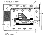
- FIG. 3 is a schematic cross-sectional view showing the relationship between the imprint apparatus and clean air during imprinting (transfer) in the present invention.
- the template (master template) 22 and the aligned photo-curing resin (resist). 27 shows a state before imprinting with a transfer substrate (replica blank) 24 coated with No. 27.
- the clean air 28 indicated by the solid line arrow is not fed into the space portion 25 by changing the direction by operating the air blowing port (not shown). Accordingly, when a gas such as He is fed, another gas such as clean air is brought in and the rate of reducing the transferability is reduced. As described above, for example, He gas is purged from the periphery of the master template into the space 25 (not shown).
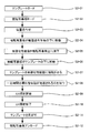
- the master template is brought into contact with the replica blank (step S09), and it is waited for a certain period of time that the applied photocurable resin (resist) is filled in the concave portions of the pattern of the master template (step S10).
- step S14 the master template is peeled off from the cured photocurable resin (step S14), and the substrate to be transferred (replica blank) having the pattern transferred to the photocurable resin is unloaded (step S15).
- the air flow changing step (S04 and S13) has been described with reference to FIG. At the latest, it can be performed before the dropping of the resist to the replica blank in step S07. Further, the air flow change in step S13 can be performed at the earliest while waiting for the resist to be filled for a certain period of time in step S10 and before the replica unloading in step S15 at the latest.
- the flow rate of the clean air sent into the space is reduced or the air flow is changed from the state where the clean air is not sent back to the original state after the light irradiation is finished (after step S2-10).
- the template is before peeling (before step S2-11).
- the photocurable resin can be cured with high accuracy, and the amount of gas that contributes to the transfer can be reduced.
- the timing of stopping the feeding of gas that contributes to the transfer is before the air flow is changed to reduce the flow rate of clean air sent into the space or to return the original state from the state where clean air is not sent.
- the template is peeled off (before step S2-11), and particularly preferably before the end of light irradiation (before step S2-10). This is because the photocurable resin can be cured with high accuracy, and the amount of gas that contributes to the transfer can be reduced.
- a transfer substrate to which a pattern is transferred is usually processed by using the patterned photocurable resin as a resist mask, and the resist mask is peeled off after the process. Is completed.
- a desired number of substrates to which the pattern is transferred can be manufactured.
- the transfer substrate moves under the ink jet head, and after applying the resist, the flow by the method of moving the replica blank under the original master template.
- the replica blank can be fixed at a fixed position, and the master template can be moved or the inkjet head can be moved.
- the flow rate and direction of clean air for keeping the inside of the imprint apparatus clean is controlled during standby when imprinting is not performed, and during imprinting, such as He suitable for transfer.
- imprinting such as He suitable for transfer.
- the transferability can be improved, and a pattern-transferred high-quality substrate to be transferred can be obtained.
- the airflow switching method of the present invention the flow rate of the gas contributing to the transfer can be reduced, and the volatilization of the photocurable resin can be suppressed.
- the imprint apparatus of the present invention will be described.
- the flow rate and direction of the air flow for keeping the inside of the imprint apparatus clean so that the photocurable resin applied to the transfer substrate by the ink jet method does not volatilize unnecessarily by the air stream of clean air.
- These are temporarily changed during imprinting. For example, the flow rate of clean air is reduced or the flow direction is changed.
- FIG. 8 is a schematic cross-sectional schematic view showing the relationship between the imprint apparatus and clean air during standby when imprinting is not being performed in the first embodiment of the present invention.
- FIG. 9 is a schematic cross-sectional schematic diagram showing the relationship between the imprint apparatus, clean air, and He gas during imprinting in the first embodiment.
- the white arrow in the figure indicates the air flow, and the black and white dot arrow indicates the He gas flow. 8 and 9 use the same reference numerals when indicating the same portions.
- the imprint apparatus 40 of this embodiment imprints the pattern of the template 42 onto the photocurable resin 47 on the transfer substrate 44 using the template 42 on which the uneven pattern is formed.
- a template holding means 41 for holding the template 42, a transferred substrate holding means 43 for holding the transferred substrate 44, and a photo-curable resin 47 is applied on the transferred substrate 44.
- a resin coating means 48 ; a moving means (not shown) for relatively moving the template 42 and the transferred substrate 44; a positioning means (not shown) for aligning the template 42 and the transferred substrate 44; Means 4 for irradiating light from above the surface on which the pattern of the template 42 is not formed while the template 42 is in contact with the photo-curable resin 47 And the space where the template 42 and the substrate to be transferred 44 contact is used as a side flow gas flow path 45, and clean air is sent from the blower opening 50 to the space 45 during standby when imprinting is not performed. At the time of feeding and imprinting, the flow rate of the clean air 46 in the space is reduced or the clean air is not fed.
- the resin applying means may be any means as long as it can apply a photocurable resin and stably drop it onto the transfer substrate, and specifically includes an ink jet device, a dispenser device, and the like. .
- the imprint apparatus reduces the flow rate of clean air in the space 45 during imprinting, or He gas 51 that contributes to transfer in a state where clean air is not sent.
- the gas is preferably sent into the space 45.
- the gas such as He gas that contributes to the transfer has a higher solubility in the photocurable resin than air, and eliminates the portion where the photocurable resin is not filled in the concave portion of the template, thereby improving the transferability. It is what you have.
- a gas such as He gas is sent to the space 45 from the blower port 50, or as shown in FIG. 9, a blower nozzle is provided around the template 42 and sent to the space 45.
- a blowing nozzle around the space portion to send a gas contributing to the transfer into the space portion. This is because the gas contributing to the transfer can be efficiently supplied to the space where imprinting is performed. Further, even when the gas contributing to the transfer is made disposable, the gas consumption can be reduced.
- the imprint apparatus includes a first partition wall 56 that defines a boundary between a first space in which the imprint apparatus performs imprinting and a second space outside the first space. And a second partition wall 57 that defines a boundary between the second space and the third space outside the second space, the second space including the temperature-adjusting fan 52, and from the third space
- the taken-in air is circulated and air-conditioned in the second space, and is blown as clean air from the upper part of the first space to the first space via an ULPA (Ultra Low Penetration Air Filter) filter 53.
- ULPA Ultra Low Penetration Air Filter
- both the resin coating means and the template device are disposed in the first space for imprinting, that is, both the space portion and the resin coating space portion are disposed, From the application of the curable resin to the completion of imprinting, it is easy to control the air flow of clean air, and the volatilization of the photocurable resin can be more effectively suppressed.
- the region where the photocurable resin is applied onto the transfer substrate by the resin applying means, the photocurable resin and the template are opposed to each other. Since the contact area is spatially integrated, the volatilization of the photocurable resin can be suppressed through the entire operation from the application of the resin to the movement of the substrate and imprinting by adjusting the flow rate adjusting means.
- the imprint apparatus 40 can change the direction of the air flow 46 of clean air that the air blowing port 50 sends into the space portion 45.
- the clean air stream 46 is sent into the space 45 from the blower port 50.
- the closed shutter 58 is closed, and the airflow 46 of clean air does not flow through the side flow duct 54.
- the damper 59 of the return duct is set to be slightly closed in conjunction with the movable shutter 58.
- a resin coating means 68 for relatively moving the template 62 and the transferred substrate 64; a positioning means (not shown) for aligning the template 62 and the transferred substrate 64; Hand that irradiates light from above the surface on which the pattern of template 62 is not formed while template 62 is in contact with photocurable resin 67 69, and the space between the template 62 and the substrate to be transferred 64 is a side flow space 65, and clean air flows from the blower port 70 to the space 65 during standby when imprinting is not performed. At the time of feeding and imprinting, the flow rate of the clean air 66 in the space portion 65 is reduced, or clean air is not sent.
- the imprint apparatus includes a first partition wall 76 that defines a boundary between a first space in which the imprint apparatus performs imprinting and a second space outside the first space. And a second partition wall 77 that defines a boundary between the second space and the third space outside the second space, and the second space includes a fan 72 with a temperature controller, from the third space
- the taken-in air is preferably circulated and air-conditioned in the second space, and is sent to the first space via an ULPA (Ultra Low Low Penetration Air Air filter) filter 73.
- ULPA Ultra Low Low Penetration Air Air filter
- the first space includes a side flow duct 74 having a ULPA filter, and an air stream of clean air is sent from the sending port 70 to the space 65 by side flow.
- the clean air filling the first space is circulated from a return duct provided in the lower part of the second space.
- the pressure is controlled so as to be positive pressure in this order, and the influence of dust is reduced.
- the imprint apparatus 60 can change the direction of the airflow 66 of clean air that the air blowing port 70 sends into the space portion 65.
- the clean air stream 66 is sent into the space 65 from the air blowing port 70, but in the imprinting example illustrated in FIG.
- the communicating ULPA filter 73 is closed by a movable shutter 78 so that the clean air stream 66 does not flow through the side flow duct 74.
Landscapes
- Physics & Mathematics (AREA)
- General Physics & Mathematics (AREA)
- Engineering & Computer Science (AREA)
- Mechanical Engineering (AREA)
- Shaping Of Tube Ends By Bending Or Straightening (AREA)
- Exposure Of Semiconductors, Excluding Electron Or Ion Beam Exposure (AREA)
Priority Applications (5)
| Application Number | Priority Date | Filing Date | Title |
|---|---|---|---|
| KR1020167017546A KR101808474B1 (ko) | 2012-10-04 | 2013-10-03 | 임프린트 방법 |
| KR1020157007709A KR101911588B1 (ko) | 2012-10-04 | 2013-10-03 | 임프린트 방법 및 임프린트 장치 |
| JP2014539825A JP5716876B2 (ja) | 2012-10-04 | 2013-10-03 | インプリント方法およびインプリント装置 |
| US14/431,592 US10279538B2 (en) | 2012-10-04 | 2013-10-03 | Imprinting method and imprinting apparatus |
| US16/356,710 US10960598B2 (en) | 2012-10-04 | 2019-03-18 | Imprinting method and imprinting apparatus |
Applications Claiming Priority (2)
| Application Number | Priority Date | Filing Date | Title |
|---|---|---|---|
| JP2012221893 | 2012-10-04 | ||
| JP2012-221893 | 2012-10-04 |
Related Child Applications (2)
| Application Number | Title | Priority Date | Filing Date |
|---|---|---|---|
| US14/431,592 A-371-Of-International US10279538B2 (en) | 2012-10-04 | 2013-10-03 | Imprinting method and imprinting apparatus |
| US16/356,710 Continuation US10960598B2 (en) | 2012-10-04 | 2019-03-18 | Imprinting method and imprinting apparatus |
Publications (1)
| Publication Number | Publication Date |
|---|---|
| WO2014054749A1 true WO2014054749A1 (ja) | 2014-04-10 |
Family
ID=50435068
Family Applications (1)
| Application Number | Title | Priority Date | Filing Date |
|---|---|---|---|
| PCT/JP2013/076973 WO2014054749A1 (ja) | 2012-10-04 | 2013-10-03 | インプリント方法およびインプリント装置 |
Country Status (5)
| Country | Link |
|---|---|
| US (2) | US10279538B2 (ko) |
| JP (2) | JP5716876B2 (ko) |
| KR (2) | KR101808474B1 (ko) |
| TW (3) | TWI609763B (ko) |
| WO (1) | WO2014054749A1 (ko) |
Cited By (7)
| Publication number | Priority date | Publication date | Assignee | Title |
|---|---|---|---|---|
| JP2015046605A (ja) * | 2012-10-04 | 2015-03-12 | 大日本印刷株式会社 | インプリント方法およびインプリント装置 |
| WO2016052345A1 (ja) * | 2014-10-01 | 2016-04-07 | 大日本印刷株式会社 | インプリント装置、インプリント方法およびインプリント装置の制御方法 |
| JP2016072624A (ja) * | 2014-10-01 | 2016-05-09 | 大日本印刷株式会社 | インプリント装置、インプリント方法およびインプリント装置の制御方法 |
| JP2016076695A (ja) * | 2014-10-07 | 2016-05-12 | 大日本印刷株式会社 | インプリント装置およびその制御方法 |
| JP2016111201A (ja) * | 2014-12-05 | 2016-06-20 | キヤノン株式会社 | インプリント装置、および物品の製造方法 |
| US20160297116A1 (en) * | 2015-04-13 | 2016-10-13 | Canon Kabushiki Kaisha | Imprint apparatus, imprint method, and method of manufacturing article |
| KR20220058671A (ko) * | 2014-04-22 | 2022-05-09 | 에베 그룹 에. 탈너 게엠베하 | 나노구조를 엠보싱하기 위한 방법 및 장치 |
Families Citing this family (15)
| Publication number | Priority date | Publication date | Assignee | Title |
|---|---|---|---|---|
| JP5804160B2 (ja) * | 2013-09-19 | 2015-11-04 | 大日本印刷株式会社 | インプリント方法およびインプリントモールドの製造方法 |
| JP6420571B2 (ja) * | 2014-06-13 | 2018-11-07 | キヤノン株式会社 | インプリント装置、インプリント方法及び物品の製造方法 |
| JP6768368B2 (ja) * | 2015-09-08 | 2020-10-14 | キヤノン株式会社 | インプリント装置、および物品の製造方法 |
| JP6566843B2 (ja) * | 2015-11-12 | 2019-08-28 | キヤノン株式会社 | パターン形成方法、インプリントシステムおよび物品製造方法 |
| US11104057B2 (en) * | 2015-12-11 | 2021-08-31 | Canon Kabushiki Kaisha | Imprint apparatus and method of imprinting a partial field |
| JP6700771B2 (ja) * | 2015-12-16 | 2020-05-27 | キヤノン株式会社 | インプリント装置、及び物品の製造方法 |
| JP6655988B2 (ja) * | 2015-12-25 | 2020-03-04 | キヤノン株式会社 | インプリント装置の調整方法、インプリント方法および物品製造方法 |
| JP6702753B2 (ja) * | 2016-02-17 | 2020-06-03 | キヤノン株式会社 | リソグラフィ装置、及び物品の製造方法 |
| JP6643135B2 (ja) * | 2016-02-17 | 2020-02-12 | キヤノン株式会社 | リソグラフィ装置および物品製造方法 |
| JP6808386B2 (ja) * | 2016-07-12 | 2021-01-06 | キヤノン株式会社 | インプリント装置および物品製造方法 |
| JP6742189B2 (ja) * | 2016-08-04 | 2020-08-19 | キヤノン株式会社 | インプリント装置、及び物品製造方法 |
| JP2018163946A (ja) * | 2017-03-24 | 2018-10-18 | 東芝メモリ株式会社 | インプリント装置およびインプリント方法 |
| US11681216B2 (en) * | 2017-08-25 | 2023-06-20 | Canon Kabushiki Kaisha | Imprint apparatus, imprint method, article manufacturing method, molding apparatus, and molding method |
| US10895806B2 (en) * | 2017-09-29 | 2021-01-19 | Canon Kabushiki Kaisha | Imprinting method and apparatus |
| WO2020121131A1 (en) * | 2018-12-11 | 2020-06-18 | Io Tech Group Ltd. | Systems and methods for preventing oxygen inhibition of a light-initiated polymerization reaction in a 3d printing system using uniform planar surfaces |
Citations (5)
| Publication number | Priority date | Publication date | Assignee | Title |
|---|---|---|---|---|
| JP2006013401A (ja) * | 2004-06-29 | 2006-01-12 | Canon Inc | 微細加工装置 |
| JP2007509769A (ja) * | 2003-10-02 | 2007-04-19 | モレキュラー・インプリンツ・インコーポレーテッド | 単一位相流体インプリント・リソグラフィ法 |
| JP2009266841A (ja) * | 2008-04-21 | 2009-11-12 | Toshiba Corp | ナノインプリント方法 |
| JP2012049471A (ja) * | 2010-08-30 | 2012-03-08 | Canon Inc | インプリント装置及び物品の製造方法 |
| JP2012186390A (ja) * | 2011-03-07 | 2012-09-27 | Canon Inc | インプリント装置および物品の製造方法 |
Family Cites Families (17)
| Publication number | Priority date | Publication date | Assignee | Title |
|---|---|---|---|---|
| KR20020057749A (ko) * | 2001-01-06 | 2002-07-12 | 윤종용 | 필터 미디엄과 필터 그리고 필터를 갖는 공기 제공 장치및 케미컬 제공 장치 |
| JP2002359180A (ja) | 2001-06-01 | 2002-12-13 | Toshiba Corp | ガス循環システム |
| US7418902B2 (en) * | 2005-05-31 | 2008-09-02 | Asml Netherlands B.V. | Imprint lithography including alignment |
| US7377764B2 (en) * | 2005-06-13 | 2008-05-27 | Asml Netherlands B.V. | Imprint lithography |
| US8105522B2 (en) * | 2008-10-29 | 2012-01-31 | Eaton Corporation | Compression mold and molding process |
| NL2004932A (en) * | 2009-07-27 | 2011-01-31 | Asml Netherlands Bv | Imprint lithography template. |
| NL2004685A (en) | 2009-07-27 | 2011-01-31 | Asml Netherlands Bv | Imprint lithography apparatus and method. |
| US20110038977A1 (en) * | 2009-08-13 | 2011-02-17 | Yong Zheng | Vertical Molding Machine |
| JP5364533B2 (ja) | 2009-10-28 | 2013-12-11 | 株式会社東芝 | インプリントシステムおよびインプリント方法 |
| JP5189114B2 (ja) * | 2010-01-29 | 2013-04-24 | 東京エレクトロン株式会社 | 基板処理装置及び基板処理方法 |
| US20110272838A1 (en) * | 2010-05-06 | 2011-11-10 | Matt Malloy | Apparatus, System, and Method for Nanoimprint Template with a Backside Recess Having Tapered Sidewalls |
| JP5489887B2 (ja) * | 2010-06-30 | 2014-05-14 | 富士フイルム株式会社 | 液体塗布装置及び液体塗布方法並びにナノインプリントシステム |
| JP5657998B2 (ja) | 2010-10-29 | 2015-01-21 | 芝浦メカトロニクス株式会社 | 液滴塗布装置及び液滴塗布方法 |
| JP2012099729A (ja) * | 2010-11-04 | 2012-05-24 | Toshiba Corp | テンプレート、テンプレートの形成方法及び半導体装置の製造方法 |
| JP2013251462A (ja) * | 2012-06-01 | 2013-12-12 | Canon Inc | インプリント装置、および、物品の製造方法 |
| WO2014054749A1 (ja) * | 2012-10-04 | 2014-04-10 | 大日本印刷株式会社 | インプリント方法およびインプリント装置 |
| JP2015179771A (ja) * | 2014-03-19 | 2015-10-08 | キヤノン株式会社 | インプリント装置、および物品の製造方法 |
-
2013
- 2013-10-03 WO PCT/JP2013/076973 patent/WO2014054749A1/ja active Application Filing
- 2013-10-03 TW TW102135954A patent/TWI609763B/zh active
- 2013-10-03 TW TW107118753A patent/TWI667146B/zh active
- 2013-10-03 US US14/431,592 patent/US10279538B2/en active Active
- 2013-10-03 KR KR1020167017546A patent/KR101808474B1/ko active IP Right Grant
- 2013-10-03 JP JP2014539825A patent/JP5716876B2/ja active Active
- 2013-10-03 TW TW106111722A patent/TWI628081B/zh active
- 2013-10-03 KR KR1020157007709A patent/KR101911588B1/ko active IP Right Grant
-
2014
- 2014-09-30 JP JP2014199671A patent/JP6115538B2/ja active Active
-
2019
- 2019-03-18 US US16/356,710 patent/US10960598B2/en active Active
Patent Citations (5)
| Publication number | Priority date | Publication date | Assignee | Title |
|---|---|---|---|---|
| JP2007509769A (ja) * | 2003-10-02 | 2007-04-19 | モレキュラー・インプリンツ・インコーポレーテッド | 単一位相流体インプリント・リソグラフィ法 |
| JP2006013401A (ja) * | 2004-06-29 | 2006-01-12 | Canon Inc | 微細加工装置 |
| JP2009266841A (ja) * | 2008-04-21 | 2009-11-12 | Toshiba Corp | ナノインプリント方法 |
| JP2012049471A (ja) * | 2010-08-30 | 2012-03-08 | Canon Inc | インプリント装置及び物品の製造方法 |
| JP2012186390A (ja) * | 2011-03-07 | 2012-09-27 | Canon Inc | インプリント装置および物品の製造方法 |
Cited By (8)
| Publication number | Priority date | Publication date | Assignee | Title |
|---|---|---|---|---|
| JP2015046605A (ja) * | 2012-10-04 | 2015-03-12 | 大日本印刷株式会社 | インプリント方法およびインプリント装置 |
| KR20220058671A (ko) * | 2014-04-22 | 2022-05-09 | 에베 그룹 에. 탈너 게엠베하 | 나노구조를 엠보싱하기 위한 방법 및 장치 |
| KR102545684B1 (ko) * | 2014-04-22 | 2023-06-20 | 에베 그룹 에. 탈너 게엠베하 | 나노구조를 엠보싱하기 위한 방법 및 장치 |
| WO2016052345A1 (ja) * | 2014-10-01 | 2016-04-07 | 大日本印刷株式会社 | インプリント装置、インプリント方法およびインプリント装置の制御方法 |
| JP2016072624A (ja) * | 2014-10-01 | 2016-05-09 | 大日本印刷株式会社 | インプリント装置、インプリント方法およびインプリント装置の制御方法 |
| JP2016076695A (ja) * | 2014-10-07 | 2016-05-12 | 大日本印刷株式会社 | インプリント装置およびその制御方法 |
| JP2016111201A (ja) * | 2014-12-05 | 2016-06-20 | キヤノン株式会社 | インプリント装置、および物品の製造方法 |
| US20160297116A1 (en) * | 2015-04-13 | 2016-10-13 | Canon Kabushiki Kaisha | Imprint apparatus, imprint method, and method of manufacturing article |
Also Published As
| Publication number | Publication date |
|---|---|
| US20150224703A1 (en) | 2015-08-13 |
| US20190210269A1 (en) | 2019-07-11 |
| KR101911588B1 (ko) | 2018-10-24 |
| KR20150065685A (ko) | 2015-06-15 |
| JP2015046605A (ja) | 2015-03-12 |
| TW201420363A (zh) | 2014-06-01 |
| KR101808474B1 (ko) | 2017-12-12 |
| JP5716876B2 (ja) | 2015-05-13 |
| TWI667146B (zh) | 2019-08-01 |
| TWI628081B (zh) | 2018-07-01 |
| TW201726430A (zh) | 2017-08-01 |
| KR20160084483A (ko) | 2016-07-13 |
| JP6115538B2 (ja) | 2017-04-19 |
| US10960598B2 (en) | 2021-03-30 |
| US10279538B2 (en) | 2019-05-07 |
| TW201836861A (zh) | 2018-10-16 |
| TWI609763B (zh) | 2018-01-01 |
| JPWO2014054749A1 (ja) | 2016-08-25 |
Similar Documents
| Publication | Publication Date | Title |
|---|---|---|
| JP6115538B2 (ja) | インプリント方法およびインプリント装置 | |
| US7811505B2 (en) | Method for fast filling of templates for imprint lithography using on template dispense | |
| KR101670115B1 (ko) | 임프린트 장치 및 물품 제조 방법 | |
| JP4398423B2 (ja) | インプリント・リソグラフィ | |
| US9759999B2 (en) | Imprinting apparatus and imprinting method thereof | |
| JP5016070B2 (ja) | インプリントリソグラフィ方法及び装置 | |
| JP5495767B2 (ja) | インプリント装置及び方法、並びに物品の製造方法 | |
| JP6628491B2 (ja) | インプリント装置、インプリント方法、および物品の製造方法 | |
| JP2010199496A (ja) | 微細構造転写装置及び微細構造転写方法 | |
| JP6650980B2 (ja) | インプリント装置、及び、物品の製造方法 | |
| WO2019078060A1 (ja) | インプリント装置、及び、物品の製造方法 | |
| JP2006303502A (ja) | インプリント・リソグラフィ | |
| Khan et al. | Smart manufacturing technologies for printed electronics | |
| JP7210155B2 (ja) | 装置、方法、および物品製造方法 | |
| JP6094257B2 (ja) | インプリント装置およびインプリント転写体の製造方法 | |
| JP6551795B2 (ja) | インプリント装置、インプリント方法およびインプリント装置の制御方法 | |
| US11454896B2 (en) | Imprint apparatus, imprinting method, and manufacturing method of article | |
| TWI709161B (zh) | 壓印裝置及物品的製造方法 | |
| JP6700949B2 (ja) | インプリント方法及び物品の製造方法 | |
| JP6402769B2 (ja) | インプリント装置およびインプリント転写体の製造方法 | |
| KR20160085947A (ko) | 임프린트 장치 및 그 방법 | |
| JP2022080673A (ja) | インプリント装置、インプリント方法及び凹凸構造体の製造方法 | |
| JP2022080723A (ja) | インプリント装置、インプリント方法及び凹凸構造体の製造方法 |
Legal Events
| Date | Code | Title | Description |
|---|---|---|---|
| 121 | Ep: the epo has been informed by wipo that ep was designated in this application |
Ref document number: 13844219 Country of ref document: EP Kind code of ref document: A1 |
|
| ENP | Entry into the national phase |
Ref document number: 2014539825 Country of ref document: JP Kind code of ref document: A |
|
| ENP | Entry into the national phase |
Ref document number: 20157007709 Country of ref document: KR Kind code of ref document: A |
|
| WWE | Wipo information: entry into national phase |
Ref document number: 14431592 Country of ref document: US |
|
| NENP | Non-entry into the national phase |
Ref country code: DE |
|
| 122 | Ep: pct application non-entry in european phase |
Ref document number: 13844219 Country of ref document: EP Kind code of ref document: A1 |