WO2014054614A1 - 液滴吐出ヘッド及び液滴吐出装置 - Google Patents
液滴吐出ヘッド及び液滴吐出装置 Download PDFInfo
- Publication number
- WO2014054614A1 WO2014054614A1 PCT/JP2013/076653 JP2013076653W WO2014054614A1 WO 2014054614 A1 WO2014054614 A1 WO 2014054614A1 JP 2013076653 W JP2013076653 W JP 2013076653W WO 2014054614 A1 WO2014054614 A1 WO 2014054614A1
- Authority
- WO
- WIPO (PCT)
- Prior art keywords
- sensor
- head module
- head
- paper
- base frame
- Prior art date
- Legal status (The legal status is an assumption and is not a legal conclusion. Google has not performed a legal analysis and makes no representation as to the accuracy of the status listed.)
- Ceased
Links
Images








Classifications
-
- B—PERFORMING OPERATIONS; TRANSPORTING
- B41—PRINTING; LINING MACHINES; TYPEWRITERS; STAMPS
- B41J—TYPEWRITERS; SELECTIVE PRINTING MECHANISMS, i.e. MECHANISMS PRINTING OTHERWISE THAN FROM A FORME; CORRECTION OF TYPOGRAPHICAL ERRORS
- B41J2/00—Typewriters or selective printing mechanisms characterised by the printing or marking process for which they are designed
- B41J2/005—Typewriters or selective printing mechanisms characterised by the printing or marking process for which they are designed characterised by bringing liquid or particles selectively into contact with a printing material
- B41J2/01—Ink jet
- B41J2/135—Nozzles
- B41J2/145—Arrangement thereof
- B41J2/155—Arrangement thereof for line printing
-
- B—PERFORMING OPERATIONS; TRANSPORTING
- B41—PRINTING; LINING MACHINES; TYPEWRITERS; STAMPS
- B41J—TYPEWRITERS; SELECTIVE PRINTING MECHANISMS, i.e. MECHANISMS PRINTING OTHERWISE THAN FROM A FORME; CORRECTION OF TYPOGRAPHICAL ERRORS
- B41J25/00—Actions or mechanisms not otherwise provided for
- B41J2025/008—Actions or mechanisms not otherwise provided for comprising a plurality of print heads placed around a drum
-
- B—PERFORMING OPERATIONS; TRANSPORTING
- B41—PRINTING; LINING MACHINES; TYPEWRITERS; STAMPS
- B41J—TYPEWRITERS; SELECTIVE PRINTING MECHANISMS, i.e. MECHANISMS PRINTING OTHERWISE THAN FROM A FORME; CORRECTION OF TYPOGRAPHICAL ERRORS
- B41J2202/00—Embodiments of or processes related to ink-jet or thermal heads
- B41J2202/01—Embodiments of or processes related to ink-jet heads
- B41J2202/19—Assembling head units
-
- B—PERFORMING OPERATIONS; TRANSPORTING
- B41—PRINTING; LINING MACHINES; TYPEWRITERS; STAMPS
- B41J—TYPEWRITERS; SELECTIVE PRINTING MECHANISMS, i.e. MECHANISMS PRINTING OTHERWISE THAN FROM A FORME; CORRECTION OF TYPOGRAPHICAL ERRORS
- B41J2202/00—Embodiments of or processes related to ink-jet or thermal heads
- B41J2202/01—Embodiments of or processes related to ink-jet heads
- B41J2202/20—Modules
Definitions
- the present invention relates to a droplet discharge device, and more particularly to a droplet discharge head having a droplet discharge head configured by connecting a plurality of head modules and a droplet discharge device.
- An ink jet recording apparatus is known as an apparatus that forms an image on a recording medium by ejecting ink as fine ink droplets (droplets) from a nozzle toward the recording medium.
- An inkjet recording apparatus records an image by a serial method in which an inkjet head (droplet ejection head) reciprocates in a direction perpendicular to the conveyance direction of a recording medium and an inkjet head is fixed without moving.
- a serial head The ink jet head mounted on the serial type ink jet recording apparatus
- a line head the ink jet head mounted on the line type ink jet recording apparatus
- the serial type ink jet recording apparatus can print on a large area recording medium by extending the distance traveled by the carriage without increasing the size of the ink jet head.
- the line-type inkjet recording apparatus can perform high-speed recording because an image can be recorded over the entire recording medium without causing the inkjet head to shuttle in the main scanning direction.
- Patent Documents 1 and 2 propose that a long inkjet head is manufactured by connecting a plurality of short inkjet heads (head modules).
- Such an ink-jet head has an advantage that even if a failure or the like occurs, only the problematic head module needs to be replaced, so that it can be economically operated.
- inkjet heads composed of a plurality of head modules connected to each other do not have their head modules accurately positioned and mounted, and unevenness in droplet ejection (so-called connection unevenness) such as streaks and unevenness occurs at the joints.
- connection unevenness unevenness in droplet ejection
- the positioning of the head module is performed by adjusting the mounting position of each head module so that the interval between adjacent head modules is within an allowable range. For this reason, it is necessary to detect the position of each head module.
- Patent Document 3 although it is an alignment method of the inkjet head, the position of the nozzle hole of the inkjet head provided in the inkjet head unit is measured with a camera, and nozzle position data is acquired based on the measurement state of the camera, A method for adjusting the position of the inkjet head based on the obtained nozzle position data has been proposed.
- Patent Document 3 has a drawback that the system becomes large because a camera must be mounted on the apparatus.
- the sensitivity may change if the sensor is not accurately positioned and attached to the object to be detected.
- the sensitivity will change if it is not accurately positioned and attached to a magnet as a detection object.
- the sensitivity may change depending on the combination with the object to be used.
- the sensitivity may change if the magnet used is changed.
- the combination of the sensor and the detection target cannot be determined uniformly. There is a problem that the sensitivity cannot be made constant.
- the present invention has been made in view of such circumstances, and an object of the present invention is to provide a droplet discharge head and a droplet discharge device capable of positioning a head module with high accuracy with a simple configuration.
- a first aspect includes a base frame, a plurality of head modules mounted side by side on the base frame, a mounting position adjusting unit that is provided for each head module and that adjusts a mounting position of the head module mounted on the base frame, and a head Displacement amount detection means for detecting the displacement amount of the head module attached to the base frame, which is provided for each module, and a detected object provided in one of the base frame and the head module, and a sensor provided in the other And a displacement amount detecting means for detecting the displacement amount of the detected object by the sensor and detecting the displacement amount of the head module attached to the base frame, and the sensor and the sensor.
- Sensor sensitivity correction information required for use Sensor-side storage means stored as side correction information, and provided in the base frame or the head module together with the detection target, sensor sensitivity correction information necessary for using the detection target is stored as detection target side correction information A to-be-detected object-side storage means.
- the plurality of head modules are mounted side by side on the base frame, whereby a droplet discharge head having a predetermined print area width is configured. That is, the head modules are connected to each other by being attached to the base frame to constitute one long droplet discharge head.
- the liquid droplet ejection head is provided with an attachment position adjusting means for adjusting the attachment position of the head module and a displacement amount detecting means for detecting the displacement amount of the head module. Therefore, the mounting position of the head module can be adjusted while checking the position.
- the displacement amount detection means is configured to include a detection target provided in one of the base frame and the head module, and a sensor provided in the other.
- the base frame or head module provided with the sensor is provided with sensor side storage means
- the base frame or head module provided with the detection object is provided with detection object side storage means.
- a sensor is provided on the base frame side and a detection target is provided on the head module side
- a sensor side storage unit is provided on the base frame
- a detection target side storage unit is provided on the head module.
- the detection target side storage unit is provided on the base frame
- the sensor side storage unit is provided on the head module.
- the sensor-side storage means stores sensor sensitivity correction information (sensor-side correction information) necessary for using the sensor
- the detected-object-side storage means stores the sensor required for using the detected object.
- Sensitivity correction information (detected body side correction information) is stored. Therefore, if the sensor side correction information and the detected object side correction information are acquired, the sensitivity of the sensor can be corrected as appropriate. It can be used with sensitivity. *
- the second mode is a mode in which the sensor-side correction information is individual information of the sensitivity of the sensor in the liquid droplet ejection head of the first mode.
- the sensor-side correction information is constituted by individual information of sensor sensitivity.
- the variation can be corrected and corrected so as to have a constant sensitivity.
- the third aspect is an aspect in which in the liquid droplet ejection head of the first or second aspect, the detected object side correction information is individual information of the detected object that affects the sensitivity of the sensor.
- the detected object side correction information is constituted by individual information of the detected object that affects the sensitivity of the sensor.
- the detected object side correction information is constituted by individual information of the detected object that affects the sensitivity of the sensor.
- the sensitivity of the object to be detected, ambient brightness, and ambient temperature vary, and the sensitivity of the laser distance sensor varies.
- the laser distance sensor can be used according to the reflectivity, ambient brightness, and ambient temperature of the detected object to be used. Sensitivity can be corrected.
- the infrared distance sensor when used as the sensor, if the reflectance or ambient temperature of the detected object, the temperature of the detected object, the color of the detected object, and the ambient brightness vary, the infrared distance sensor Sensitivity varies, but by storing information on the reflectance of the detected object, the ambient temperature, the temperature of the detected object, the color of the detected object, and the ambient brightness as individual information of the detected object The sensitivity of the infrared distance sensor can be corrected according to the reflectance of the detection target to be used, the ambient temperature, the temperature of the detection target, the color of the detection target, and the ambient brightness.
- the sensitivity of the eddy current sensor varies when the conductivity and permeability of the detected object and the temperature of the detected object vary.
- the sensitivity of the eddy current sensor can be corrected according to the eddy current of the detected object to be used.
- the fourth aspect is an aspect in which, in the liquid droplet ejection head according to any one of the first to third aspects, the sensor-side correction information is information on a sensor mounting position.
- the sensor-side correction information is constituted by information on the mounting position of the sensor.
- the sensitivity may change if the sensor and the object to be detected are not accurately positioned and mounted.
- information on the mounting position of the sensor for example, normal (Information on the amount of displacement with respect to the mounting position) is stored, it is possible to appropriately correct the change in sensitivity based on the displacement of the mounting position.
- this makes it possible to roughen the assembly of the sensor and facilitate the manufacture of the droplet discharge head.
- the detected-object-side correction information is information on an attachment position of the detected object.
- the detected object side correction information includes information on the mounting position of the detected object.
- the sensitivity may change. Even in such a case, information on the attachment position of the object to be detected (for example, (Information on the amount of deviation with respect to the normal attachment position) is stored, the change in sensitivity based on the deviation of the attachment position can be corrected appropriately. In addition, this makes it possible to roughen the assembly of the detection target and facilitate the manufacture of the droplet discharge head.
- the sixth aspect is an aspect in which the sensor-side correction information is information on the ambient temperature of the sensor in the liquid droplet ejection head according to any one of the first to fifth aspects.
- the sensor side correction information is constituted by information on the ambient temperature of the sensor.
- the sensitivity may change depending on the temperature. Therefore, by storing information on the ambient temperature of the sensor as sensor-side correction information, it is possible to appropriately correct sensitivity changes based on temperature changes.
- a seventh aspect is an aspect in which in the liquid droplet ejection head according to any one of the first to sixth aspects, the detected object side correction information is information on the ambient temperature of the detected object.
- the detection-object-side correction information includes information on the ambient temperature of the detection object.
- the effect on the sensitivity of the sensor may change depending on the temperature.
- the magnetic force of the magnet changes with temperature, and the sensitivity of the magnetic sensor changes. Even in such a case, it is possible to appropriately correct the change in the sensitivity of the sensor based on the temperature change by storing the information on the ambient temperature of the detected object.
- the eighth aspect is an aspect in which, in the liquid droplet ejection head according to any one of the first to seventh aspects, the sensor is a magnetic sensor and the detection target is a magnet.
- the senor is configured by a magnetic sensor, and the detection target is configured by a magnet. Since the magnetic sensor has high resolution and is small, even when incorporated in a droplet discharge head, it is possible to detect displacement with high accuracy without increasing the size of the head.
- a ninth aspect is an aspect in which in the liquid droplet ejection head of the eighth aspect, the detected object side correction information is the magnetic force of the magnet.
- the detected object side correction information is configured by the magnetic force of the magnet. If there is variation in the magnetic force of the magnet, the sensitivity of the magnetic sensor will vary, but by storing the magnetic force information of the magnet as individual information of the detected object, the magnetic sensor Sensitivity can be corrected.
- a tenth aspect is an aspect in which the sensor is a laser position sensor in the liquid droplet ejection apparatus according to any one of the first to seventh aspects.
- the senor is configured by a laser position sensor. Since the laser position sensor has high resolution and is small, even when incorporated in a droplet discharge head, it is possible to detect displacement with high accuracy without increasing the size of the head. *
- the detected object side correction information is at least one of the reflectance of the detected object, the ambient brightness, and the ambient temperature. It is an aspect. *
- the detected object side correction information is configured by at least one of the reflectance of the detected object, the ambient brightness, and the ambient temperature. (Consists of information on the reflectance, ambient brightness, and ambient temperature of an object to be detected alone or in combination.)
- the sensitivity of the laser distance sensor varies, but the detected object as individual information of the detected object
- a twelfth aspect is an aspect in which the sensor is an infrared distance sensor in the droplet discharge device according to any one of the first to seventh aspects.
- the senor is configured by an infrared distance sensor. Since the infrared distance sensor has high resolution and is small, even if it is incorporated in a droplet discharge head, it can detect displacement with high precision without increasing the size of the head. *
- the detection target side correction information includes the reflectance of the detection target, the ambient temperature, the temperature of the detection target, the color of the detection target, and It is an aspect that is at least one of ambient brightness.
- the detected object side correction information includes the reflectance of the detected object, the ambient temperature, the temperature of the detected object, the color of the detected object, and the surroundings. (The detected object's reflectivity, ambient temperature, detected object's temperature, detected object's color, and ambient brightness information, either alone or in combination) .)
- the sensitivity of the infrared distance sensor varies when the reflectance of the detected object, the ambient temperature, the detected object temperature, the detected object color, and the ambient brightness vary.
- the sensitivity of the infrared distance sensor can be corrected according to the reflectance of the detection object, the ambient temperature, the temperature of the detection object, the color of the detection object, and the ambient brightness.
- a fourteenth aspect is an aspect in which the sensor is an eddy current sensor in the liquid droplet ejection apparatus according to any one of the first to seventh aspects.
- the senor is constituted by an eddy current sensor. Since the eddy current sensor has high resolution and is small, even when incorporated in a droplet discharge head, it is possible to detect displacement with high accuracy without increasing the size of the head.
- the detected object side correction information is at least one of the conductivity of the detected object, the magnetic permeability, and the temperature of the detected object. It is. *
- the detected object side correction information is configured by at least one of the conductivity, magnetic permeability, and temperature of the detected object.
- Each information of conductivity, magnetic permeability, and temperature of the object to be detected is configured singly or in combination.
- an eddy current sensor is used as a sensor, if the conductivity, magnetic permeability, or temperature of the detected object varies, the sensitivity of the eddy current sensor varies, but it is detected as individual information of the detected object.
- the sensitivity of the eddy current sensor is corrected according to the conductivity and permeability of the object to be detected and the temperature of the object to be detected. can do.
- the detection target side correction information is acquired from the detection target side storage unit, and the detection target side correction information is acquired. It is an aspect further comprising sensitivity correction means for acquiring sensor-side correction information of the sensor that uses the body from the sensor-side storage means, and performing sensor sensitivity correction processing.
- the sensor-side correction information is acquired from the sensor-side storage means corresponding to the sensor, and the detection-object-side storage means corresponding to the detection object is acquired.
- the detected object side correction information is acquired, and the sensitivity of the sensor is automatically corrected.
- the sensitivity of the sensor can be automatically made constant in all the displacement amount detection means.
- the attachment position adjusting means is provided on a positioning reference pin provided on one of the base frame and the head module and on the other.
- An eccentric roller comprising an eccentric roller and biasing means for biasing the head module in the position adjustment direction of the head module and pressing and contacting the eccentric roller to the positioning reference pin. In this mode, the roller is rotated to move the head module in the head module position adjustment direction.
- the attachment position adjusting means includes the positioning reference pin provided on one of the base frame and the head module, the eccentric roller provided on the other, and the urging means. Thereby, the mounting position of the head module can be adjusted with high accuracy.
- the detection target side correction information is acquired from the droplet discharge head according to any one of the first to seventeenth aspects and the detection target side storage unit, and the detection target side correction information is acquired.
- the liquid droplet ejection apparatus includes: sensitivity correction means that acquires sensor-side correction information of a sensor that uses the body from the sensor-side storage means and performs sensor sensitivity correction processing.
- the sensor-side correction information is acquired from the sensor-side storage means corresponding to the sensor, and the detection-object-side storage means corresponding to the detection object is acquired.
- the detected object side correction information is acquired, and the sensitivity of the sensor is automatically corrected.
- the sensitivity of the sensor can be automatically made constant in all the displacement amount detection means.
- the head module can be positioned with high accuracy with a simple configuration.
- FIG. 1 shows an overall schematic configuration of an inkjet recording apparatus
- Block diagram showing schematic configuration of control system of inkjet recording apparatus
- Bottom view showing structure of main part of inkjet head
- An enlarged view of a part of FIG. Front view showing the structure of the main part of an inkjet head Side view showing structure of main part of inkjet head
- Head module front view Rear view of the head module Side sectional view of the head module
- Front view showing the structure of the main part of the base frame
- Side sectional view showing the structure of the main part of the base frame Illustration of how to install the head module Illustration of how to install the head module
- Explanatory drawing of head module positioning method Explanatory drawing of head module positioning method
- Schematic configuration diagram of inkjet head for correcting sensitivity of magnetic sensor Front view showing another example of the front view of the head module
- FIG. 1 is an overall configuration diagram showing an overall schematic configuration of an inkjet recording apparatus. *
- the ink jet recording apparatus 10 is an ink jet recording apparatus that records a color image by ejecting ink of four colors of cyan (C), magenta (M), yellow (Y), and black (K) onto a sheet.
- C cyan
- M magenta
- Y yellow
- K black
- General-purpose printing paper is used for the sheet as the recording medium.
- an ultraviolet curable aqueous ink is used as the ink.
- the general-purpose printing paper is not so-called ink-jet dedicated paper but means paper mainly composed of cellulose such as coated paper used for general offset printing.
- Water-based inks are inks in which coloring materials such as dyes and pigments are dissolved or dispersed in water and water-soluble solvents. UV-curable water-based inks are cured by irradiation with ultraviolet rays (UV). This type of water-based ink. *
- General-purpose printing paper has penetrability, and when an image is recorded on such a recording medium using an aqueous ink as it is, feathering, bleeding or the like occurs. For this reason, in the ink jet recording apparatus of this example, an image is recorded by applying in advance a processing liquid having a function of aggregating components in the ink.
- an inkjet recording apparatus 10 mainly includes a paper feeding unit 12 that feeds paper P as a recording medium, and a surface (image recording surface) of the paper P fed from the paper feeding unit 12.
- a treatment liquid application unit 14 for applying the treatment liquid, a treatment liquid drying treatment unit 16 for drying the paper P coated with the treatment liquid, and ink droplets are ejected onto the surface of the dried paper P by an inkjet method.
- a paper discharge unit 24 that discharges and collects the paper P irradiated with ultraviolet rays.
- the paper feed unit 12 feeds the paper P loaded on the paper feed tray 30 to the processing liquid coating unit 14 one by one.
- the paper feed unit 12 mainly includes a paper feed stand 30, a soccer device 32, a paper feed roller pair 34, a feeder board 36, a front pad 38, and a paper feed drum 40.
- the paper P is placed on the paper feed table 30 in a bundle state in which a large number of sheets are stacked.
- the sheet feed table 30 is provided so as to be lifted and lowered by a sheet feed table lifting device (not shown).
- the paper feed platform lifting device is driven in conjunction with the increase / decrease of the paper P stacked on the paper feed platform 30 so that the paper P positioned at the top of the bundle is always at a constant height.
- the paper feed table 30 is moved up and down. *
- the soccer device 32 picks up the sheets P stacked on the sheet feeding table 30 one by one from the top and feeds them to the pair of sheet feeding rollers 34.
- the soccer device 32 includes a suction foot 32A that is movable up and down and swingable.
- the suction foot 32A sucks and holds the upper surface of the paper P, and the paper P is fed from the paper feed table 30 to the paper feed roller pair 34.
- Transport At this time, the suction foot 32A sucks and holds the top surface of the front end side of the paper P positioned at the top of the bundle, pulls up the paper P, and the pair of paper P that constitutes the paper feed roller pair 34 is pulled up. Insert between rollers 34A, 34B. *
- the paper feed roller pair 34 includes a pair of upper and lower rollers 34A and 34B that are pressed against each other.
- One of the pair of upper and lower rollers 34A and 34B is a drive roller (roller 34A) and the other is a driven roller (roller 34B).
- the drive roller (roller 34A) is driven by a motor (not shown) and rotates.
- the motor is driven in conjunction with the feeding of the paper P.
- the motor rotates the driving roller (roller 34A) in accordance with the timing.
- the sheet P inserted between the pair of upper and lower rollers 34A, 34B is nipped by the rollers 34A, 34B and is sent out in the rotation direction of the rollers 34A, 34B (the installation direction of the feeder board 36).
- the feeder board 36 is formed corresponding to the paper width, and receives the paper P sent out from the paper feed roller pair 34 and guides it to the front pad 38.
- the feeder board 36 is installed such that the front end side is inclined downward, and the sheet P placed on the conveyance surface is slid along the conveyance surface and guided to the front pad 38.
- a plurality of tape feeders 36A for conveying the paper P are installed at intervals in the width direction.
- the tape feeder 36A is formed in an endless shape, and is driven to rotate by a motor (not shown).
- the paper P placed on the conveyance surface of the feeder board 36 is fed by the tape feeder 36A and conveyed on the feeder board 36.
- a retainer 36B and a roller 36C are installed on the feeder board 36. *
- a plurality of retainers 36 ⁇ / b> B are arranged in a longitudinal line along the conveyance surface of the paper P (two in this example).
- the retainer 36 ⁇ / b> B is configured by a leaf spring having a width corresponding to the sheet width, and is placed in pressure contact with the conveyance surface.
- the paper P conveyed on the feeder board 36 by the tape feeder 36A passes through the retainer 36B, so that the unevenness is corrected.
- the retainer 36 ⁇ / b> B is formed by curling the rear end portion so that the paper P can be easily introduced between the retainer 36 ⁇ / b> B and the feeder board 36.
- the roller 36C is disposed between the front and rear retainers 36B.
- the roller 36C is placed in pressure contact with the transport surface of the paper P.
- the sheet P conveyed between the front and rear retainers 36B is conveyed while the upper surface is suppressed by the rollers 36C.
- the front pad 38 corrects the posture of the paper P.
- the front pad 38 is formed in a plate shape and is disposed orthogonal to the transport direction of the paper P. Further, it is driven by a motor (not shown) so as to be swingable.
- the leading edge of the sheet P conveyed on the feeder board 36 is brought into contact with the front pad 38 to correct the posture (so-called skew prevention).
- the front pad 38 swings in conjunction with the paper feeding to the paper feeding drum 40 and delivers the paper P whose posture has been corrected to the paper feeding drum 40.
- the paper feed drum 40 receives the paper P fed from the feeder board 36 via the front pad 38 and conveys it to the processing liquid coating unit 14.
- the paper supply drum 40 is formed in a cylindrical shape and is driven to rotate by a motor (not shown).
- a gripper 40A is provided on the outer peripheral surface of the paper feed drum 40, and the leading edge of the paper P is gripped by the gripper 40A.
- the paper feed drum 40 conveys the paper P to the processing liquid coating unit 14 while winding the paper P around the peripheral surface by gripping and rotating the leading edge of the paper P with the gripper 40A.
- the paper feed unit 12 is configured as described above.
- the sheets P stacked on the sheet feeding table 30 are pulled up one by one in order from the top by the soccer device 32 and fed to the pair of sheet feeding rollers 34.
- the paper P fed to the paper feed roller pair 34 is fed forward by a pair of upper and lower rollers 34A, 34B constituting the paper feed roller pair 34 and placed on the feeder board 36.
- the paper P placed on the feeder board 36 is transported by a tape feeder 36 ⁇ / b> A provided on the transport surface of the feeder board 36.
- the retainer 36B is pressed against the transport surface of the feeder board 36 in the transport process, and the unevenness is corrected.
- the sheet P conveyed by the feeder board 36 has its leading end brought into contact with the front pad 38 to correct the inclination, and is then transferred to the sheet feeding drum 40. Then, it is transported to the processing liquid coating unit 14 by the paper feed drum 40.
- the treatment liquid application unit 14 applies a treatment liquid having a function of aggregating ink on the surface (image recording surface) of the paper P.
- the treatment liquid application unit 14 mainly includes a treatment liquid application drum 42 that conveys the paper P, and a treatment liquid application device that applies the treatment liquid to the surface (image recording surface) of the paper P conveyed by the treatment liquid application drum 42. 44. *
- the treatment liquid coating drum 42 functions as a holding unit (recording medium holding unit) for the sheet P as a recording medium, and also functions as a conveying unit (recording medium conveying unit) for the sheet P as a recording medium.
- the sheet P is received from the sheet feeding drum 40, held on the outer peripheral surface and rotated to convey the sheet P to the processing liquid drying processing unit 16.
- the treatment liquid coating drum 42 is formed in a cylindrical shape and is driven to rotate by a motor (not shown).
- a gripper 42A is provided on the outer peripheral surface of the treatment liquid coating drum 42, and the leading edge of the paper P is gripped by the gripper 42A.
- the processing liquid coating drum 42 conveys the paper P to the processing liquid drying processing unit 16 while rotating the paper P around the peripheral surface by rotating the gripper 42A by gripping the leading end of the paper P (one rotation). To transport one sheet of paper P).
- the rotation of the processing liquid coating drum 42 and the paper feed drum 40 is controlled so that the timing of receiving and delivering the paper P is matched. That is, it drives so that it may become the same peripheral speed, and it drives so that the position of a mutual gripper may match.
- the treatment liquid application device 44 functions as a treatment liquid application unit that applies the treatment liquid to the surface of the paper P conveyed by the treatment liquid application drum 42.
- the treatment liquid coating device 44 is constituted by, for example, a roller coating device, and applies a treatment liquid to the surface of the paper P by pressing and abutting a coating roller having a treatment liquid applied to the peripheral surface thereof on the surface of the paper P.
- the treatment liquid coating apparatus 44 may be configured by, for example, a head that ejects and applies a treatment liquid by an inkjet method, or a spray that sprays and applies the treatment liquid. *
- the treatment liquid application unit 14 is configured as described above.
- the paper P delivered from the paper supply drum 40 of the paper supply unit 12 is received by the processing liquid application drum 42.
- the treatment liquid coating drum 42 grips the leading end of the paper P with the gripper 42 ⁇ / b> A and rotates, so that the paper P is wound around the circumferential surface and conveyed. In this conveyance process, the application roller is pressed against the surface of the paper P, the application roller rolls on the paper, and the processing liquid is applied to the surface of the paper P.
- the treatment liquid applied by the treatment liquid application unit 14 is composed of a liquid containing an aggregating agent that aggregates the components in the ink composition.
- the flocculant may be a compound that can change the pH of the ink composition, a polyvalent metal salt, or a polyallylamine.
- Preferred examples of the compound capable of lowering the pH include highly water-soluble acidic substances (phosphoric acid, oxalic acid, malonic acid, citric acid, derivatives of these compounds, or salts thereof).
- An acidic substance may be used individually by 1 type, and may use 2 or more types together. Thereby, cohesion can be improved and the whole ink can be fixed.
- the pH (25 ° C.) of the ink composition is 8.0 or more, and the pH (25 ° C.) of the treatment liquid is preferably in the range of 0.5-4. As a result, it is possible to increase the image density, resolution, and speed of inkjet recording.
- the treatment liquid may contain additives such as, for example, drying inhibitors (wetting agents), antifading agents, emulsion stabilizers, penetration enhancers, ultraviolet absorbers, preservatives, antifungal agents, pH adjusters, It can contain known additives such as surface tension modifiers, antifoaming agents, viscosity modifiers, dispersants, dispersion stabilizers, rust inhibitors and chelating agents.
- drying inhibitors wetting agents
- antifading agents emulsion stabilizers
- penetration enhancers ultraviolet absorbers
- preservatives antifungal agents
- pH adjusters emulsion stabilizers
- additives such as surface tension modifiers, antifoaming agents, viscosity modifiers, dispersants, dispersion stabilizers, rust inhibitors and chelating agents.
- the processing liquid drying processing unit 16 performs a drying process on the paper P having a processing liquid applied to the surface.
- the processing liquid drying processing unit 16 mainly blows hot air on the processing liquid drying processing drum 46 that transports the paper P, the paper transport guide 48, and the image recording surface of the paper P that is transported by the processing liquid drying processing drum 46.
- a treatment liquid drying processing unit 50 that is applied and dried is configured.
- the processing liquid drying processing drum 46 receives the paper P from the processing liquid coating drum 42 of the processing liquid coating unit 14 and conveys the paper P to the image recording unit 18.
- the processing liquid drying processing drum 46 is constituted by a frame assembled in a cylindrical shape, and is driven to rotate by a motor (not shown).
- a gripper 46A is provided on the outer peripheral surface of the processing liquid drying processing drum 46, and the leading edge of the paper P is gripped by the gripper 46A.
- the processing liquid drying processing drum 46 conveys the image recording unit 18 and the paper P by gripping and rotating the leading edge of the paper P with the gripper 46A.
- the treatment liquid drying treatment drum 46 of this example is configured so that grippers 42A are disposed at two locations on the outer peripheral surface so that two sheets of paper P can be conveyed by one rotation.
- the rotations of the processing liquid drying processing drum 46 and the processing liquid coating drum 42 are controlled so that the timing of receiving and delivering the paper P matches each other. That is, it drives so that it may become the same peripheral speed, and it drives so that the position of a mutual gripper may match.
- the paper transport guide 48 is disposed along the transport path of the paper P by the processing liquid drying processing drum 46 and guides the transport of the paper P.
- the processing liquid drying processing unit 50 is installed inside the processing liquid drying processing drum 46 and performs drying processing by blowing hot air toward the surface of the paper P conveyed by the processing liquid drying processing drum 46.
- the two processing liquid drying processing units 50 are arranged in the processing liquid drying processing drum, and are configured to blow hot air toward the surface of the paper P conveyed by the processing liquid drying processing drum 46. ing. *
- the processing liquid drying processing unit 16 is configured as described above.
- the paper P delivered from the treatment liquid application drum 42 of the treatment liquid application unit 14 is received by the treatment liquid drying treatment drum 46.
- the processing liquid drying processing drum 46 conveys the paper P by gripping the leading end of the paper P with the gripper 46 ⁇ / b> A and rotating. At this time, the treatment liquid drying treatment drum 46 conveys the surface of the paper P (the surface coated with the treatment liquid) inward.
- the paper P is dried by blowing hot air from the processing liquid drying processing unit 50 installed inside the processing liquid drying processing drum 46. That is, the solvent component in the treatment liquid is removed. As a result, an ink aggregation layer is formed on the surface of the paper P.
- the image recording unit 18 ejects ink of each color of C, M, Y, and K on the image recording surface of the paper P, and draws a color image on the image recording surface of the paper P.
- the image recording unit 18 mainly presses the image recording drum 52 that conveys the paper P and the paper P that is conveyed by the image recording drum 52, so that the paper P is brought into close contact with the peripheral surface of the image recording drum 52.
- a roller 54 a head unit 56 that records an image by discharging ink droplets of C, M, Y, and K colors on the paper P, and an inline sensor 58 that serves as an image reading unit that reads the image recorded on the paper P And a mist filter 60 for capturing ink mist and a drum cooling unit 62 for cooling the image recording drum 52.
- the image recording drum 52 functions as a recording medium holding unit that holds the paper P as a recording medium, and also functions as a recording medium conveyance unit that conveys the paper P as a recording medium.
- the image recording drum 52 receives the paper P from the processing liquid drying processing drum 46 of the processing liquid drying processing unit 16 and conveys the paper P to the ink drying processing unit 20.
- the image recording drum 52 is formed in a cylindrical shape, and is rotated by being driven by a motor (not shown) as a driving unit.
- a gripper is provided on the outer peripheral surface of the image recording drum 52, and the leading end of the paper P is gripped by the gripper.
- the image recording drum 52 conveys the paper P to the ink drying processing unit 20 while wrapping the paper P around the peripheral surface by gripping and rotating the leading edge of the paper P with this gripper. Further, the image recording drum 52 has a large number of suction holes (not shown) formed in a predetermined pattern on the peripheral surface thereof. The paper P wound around the peripheral surface of the image recording drum 52 is conveyed while being sucked and held on the peripheral surface of the image recording drum 52 by being sucked from the suction holes. Thereby, the paper P can be conveyed with high flatness. *
- the paper pressing roller 54 is disposed in the vicinity of the paper receiving position of the image recording drum 52 (the position where the paper P is received from the processing liquid drying processing drum 46).
- the sheet pressing roller 54 is composed of a rubber roller, and is installed in press contact with the peripheral surface of the image recording drum 52.
- the paper P transferred from the processing liquid drying processing drum 46 to the image recording drum 52 is nipped by passing through the paper pressing roller 54 and is brought into close contact with the peripheral surface of the image recording drum 52.
- the head unit 56 includes an inkjet head (droplet ejection head) 200C that ejects cyan (C) ink droplets by an inkjet method, and an inkjet head (droplet ejection head) that ejects magenta (M) ink droplets by an inkjet method.
- 200M an inkjet head (droplet ejection head) 200Y that ejects yellow (Y) ink droplets by an inkjet method
- an inkjet head (droplet ejection head) 200K that ejects black (K) ink droplets by an inkjet method It is comprised with.
- Each of the inkjet heads 200C, 200M, 200Y, and 200K is disposed at a constant interval along the conveyance path of the paper P by the image recording drum 52. *
- Each of the inkjet heads 200C, 200M, 200Y, and 200K is composed of a line head, and is formed with a length corresponding to the maximum sheet width.
- Each of the inkjet heads 200C, 200M, 200Y, and 200K is disposed such that the nozzle surface (surface on which the nozzles are arranged) faces the peripheral surface of the image recording drum 52.
- Each of the inkjet heads 200C, 200M, 200Y, and 200K ejects ink droplets from the nozzles formed on the nozzle surface toward the image recording drum 52, whereby an image is printed on the paper P conveyed by the image recording drum 52. Record. *
- the inline sensor 58 functions as an image reading unit that reads an image recorded on the paper P.
- the inline sensor 58 is installed on the downstream side of the rearmost inkjet head 200K with respect to the conveyance direction of the paper P by the image recording drum 52, and reads an image recorded by the inkjet heads 200C, 200M, 200Y, and 200K.
- the in-line sensor 58 is constituted by, for example, a line scanner, and reads an image recorded by the inkjet heads 200C, 200M, 200Y, and 200K from the paper P conveyed by the image recording drum 52. *
- a contact prevention plate 59 is installed in the vicinity of the inline sensor 58 on the downstream side of the inline sensor 58.
- the contact prevention plate 59 prevents the paper P from coming into contact with the in-line sensor 58 when the paper P is lifted due to a conveyance failure or the like.
- the mist filter 60 is disposed between the rearmost inkjet head 200K and the inline sensor 58, and sucks air around the image recording drum 52 to capture the ink mist. In this way, by sucking the air around the image recording drum 52 and capturing the ink mist, the ink mist can be prevented from entering the in-line sensor 58 and reading errors can be prevented.
- the drum cooling unit 62 cools the image recording drum 52 by blowing cold air onto the image recording drum 52.
- the drum cooling unit 62 mainly includes an air conditioner (not shown) and a duct 62 ⁇ / b> A that blows cool air supplied from the air conditioner onto the peripheral surface of the image recording drum 52.
- the duct 62 ⁇ / b> A cools the image recording drum 52 by blowing cool air to an area other than the conveyance area of the paper P against the image recording drum 52.
- the duct 62A blows cold air to the area of the lower half of the image recording drum 52 to record the image.
- the drum 52 is cooled.
- the air outlet of the duct 62 ⁇ / b> A is formed in an arc shape so as to cover substantially the lower half of the image recording drum 52, and cold air is blown to the region of the substantially lower half of the image recording drum 52.
- the temperature for cooling the image recording drum 52 is determined by the relationship with the temperature of the inkjet heads 200C, 200M, 200Y, and 200K (particularly the temperature of the nozzle surface), and is higher than the temperature of the inkjet heads 200C, 200M, 200Y, and 200K. It is cooled to a low temperature. Thereby, it is possible to prevent condensation from occurring in the ink jet heads 200C, 200M, 200Y, and 200K. That is, by making the temperature of the image recording drum 52 lower than that of the inkjet heads 200C, 200M, 200Y, and 200K, condensation can be induced on the image recording drum side, and the condensation that occurs on the inkjet heads 200C, 200M, 200Y, and 200K. (Especially, condensation on the nozzle surface) can be prevented. *
- the image recording unit 18 is configured as described above.
- the paper P delivered from the processing liquid drying processing drum 46 of the processing liquid drying processing unit 16 is received by the image recording drum 52.
- the image recording drum 52 conveys the paper P by gripping the leading edge of the paper P with a gripper and rotating.
- the paper P delivered to the image recording drum 52 is first brought into close contact with the peripheral surface of the image recording drum 52 by passing through the paper pressing roller 54. At the same time, it is sucked from the suction holes of the image recording drum 52 and sucked and held on the outer peripheral surface of the image recording drum 52.
- the paper P is transported in this state and passes through the inkjet heads 200C, 200M, 200Y, and 200K.
- ink droplets of each color of C, M, Y, and K are ejected from the inkjet heads 200C, 200M, 200Y, and 200K onto the surface, and a color image is drawn on the surface. Since the ink aggregation layer is formed on the surface of the paper P, a high-quality image can be recorded without causing feathering or bleeding.
- the paper P on which the image is recorded by the ink jet heads 200C, 200M, 200Y, and 200K then passes through the inline sensor 58. Then, an image recorded on the surface when the in-line sensor 58 passes is read. Reading of the recorded image is performed as necessary, and an inspection such as ejection failure is performed from the read image. When reading is performed, reading is performed in a state of being held by suction on the image recording drum 52, so that reading can be performed with high accuracy. Further, since reading is performed immediately after image recording, for example, abnormalities such as ejection failure can be detected immediately, and it is possible to respond quickly. As a result, it is possible to prevent wasteful recording and minimize the occurrence of waste paper. *
- the ink drying processing unit 20 performs drying processing on the paper P after image recording, and removes liquid components remaining on the surface of the paper P.
- the ink drying processing unit 20 is transported by the chain gripper 64 that transports the paper P on which an image is recorded, the back tension applying mechanism 66 that applies back tension to the paper P transported by the chain gripper 64, and the chain gripper 64.
- the chain gripper 64 is a paper transport mechanism commonly used in the ink drying processing unit 20, the ultraviolet irradiation unit 22, and the paper discharge unit 24.
- the chain gripper 64 receives the paper P delivered from the image recording unit 18 and discharges it. Transport to section 24.
- the chain gripper 64 mainly includes a first sprocket 64A installed in the vicinity of the image recording drum 52, a second sprocket 64B installed in the paper discharge unit 24, a first sprocket 64A, and a second sprocket 64B.
- the endless chain 64C is wound around, a plurality of chain guides (not shown) for guiding the running of the chain 64C, and a plurality of grippers 64D attached to the chain 64C at a constant interval.
- the first sprocket 64 ⁇ / b> A, the second sprocket 64 ⁇ / b> B, the chain 64 ⁇ / b> C, and the chain guide are each configured as a pair, and are disposed on both sides of the paper P in the width direction.
- the gripper 64D is installed over a chain 64C provided as a pair. *
- the first sprocket 64A is installed close to the image recording drum 52 so that the paper P delivered from the image recording drum 52 can be received by the gripper 64D.
- the first sprocket 64A is rotatably supported by a bearing (not shown) and is connected to a motor (not shown).
- the chain 64C wound around the first sprocket 64A and the second sprocket 64B travels by driving this motor.
- the second sprocket 64B is installed in the paper discharge unit 24 so that the paper P received from the image recording drum 52 can be collected by the paper discharge unit 24. That is, the installation position of the second sprocket 64B is the end of the transport path of the paper P by the chain gripper 64.
- the second sprocket 64B is pivotally supported by a bearing (not shown) and is rotatably provided. *
- the chain 64C is formed in an endless shape and is wound around the first sprocket 64A and the second sprocket 64B.
- the second sprocket 64B is disposed at a position higher than the first sprocket 64A. For this reason, a travel route in which the chain 64C is inclined in the middle is formed. Specifically, it includes a first horizontal transfer path 70A, an inclined transfer path 70B, and a second horizontal transfer path 70C.
- the second horizontal conveyance path 70C is set to the same height as the second sprocket 64B, and the chain 64C wound around the second sprocket 64B is set to travel horizontally.
- the inclined conveyance path 70B is set between the first horizontal conveyance path 70A and the second horizontal conveyance path 70C, and is set so as to connect the first horizontal conveyance path 70A and the second horizontal conveyance path 70C.
- the chain guide is disposed so as to form the first horizontal conveyance path 70A, the inclined conveyance path 70B, and the second horizontal conveyance path 70C. Specifically, it is disposed at at least a junction point between the first horizontal conveyance path 70A and the inclined conveyance path 70B and a junction point between the inclined conveyance path 70B and the second horizontal conveyance path 70C.
- a plurality of grippers 64D are attached to the chain 64C at a constant interval.
- the mounting interval of the gripper 64D is set in accordance with the receiving interval of the paper P from the image recording drum 52. That is, it is set according to the reception interval of the paper P from the image recording drum 52 so that the paper P sequentially delivered from the image recording drum 52 can be received from the image recording drum 52 at the same timing.
- the chain gripper 64 is configured as described above. As described above, when a motor (not shown) connected to the first sprocket 64A is driven, the chain 64C travels. The chain 64C travels at the same speed as the peripheral speed of the image recording drum 52. The timing is adjusted so that the paper P delivered from the image recording drum 52 can be received by each gripper 64D. *
- the back tension applying mechanism 66 applies a back tension to the paper P that is conveyed while its leading end is gripped by the chain gripper 64.
- the back tension applying mechanism 66 mainly includes a guide plate 72 and a suction mechanism (not shown) that sucks air from suction holes (not shown) formed in the guide plate 72.
- the guide plate 72 is a hollow box plate having a width corresponding to the paper width.
- the sheet P conveyed by the chain gripper 64 has its back surface (the surface on which no image is recorded) sliding on the upper surface of the guide plate 72 (the surface facing the chain 64C: the sliding contact surface). Be transported. *
- a large number of suction holes are formed in a predetermined pattern on the sliding contact surface (upper surface) of the guide plate 72.
- the guide plate 72 is formed of a hollow box plate.
- a suction mechanism (not shown) sucks the hollow portion (inside) of the guide plate 72. As a result, air is sucked from the suction holes formed in the sliding contact surface.
- the guide plate 72 is disposed along the chain 64C that travels along the first horizontal conveyance path 70A and the inclined conveyance path 70B, the guide plate 72 conveys the first horizontal conveyance path 70A and the inclined conveyance path 70B. While it is being applied, back tension is applied.
- the ink drying processing unit 68 is installed inside the chain gripper 64 (particularly a part constituting the first horizontal transport path 70A), and performs a drying process on the paper P transported through the first horizontal transport path 70A.
- the ink drying processing unit 68 performs a drying process by blowing hot air onto the surface of the paper P transported through the first horizontal transport path 70A.
- the humidity of the ink drying process part 20 rises by performing a drying process. Since the drying process cannot be performed efficiently when the humidity increases, the ink drying processing unit 20 is provided with an exhaust unit together with the ink drying processing unit 68 to forcibly exhaust the humid air generated by the drying process.
- the exhaust unit may be configured such that an exhaust duct is installed in the ink drying processing unit 20 and the air of the ink drying processing unit 20 is exhausted by the exhaust duct.
- the ink drying processing unit 20 is configured as described above.
- the paper P delivered from the image recording drum 52 of the image recording unit 18 is received by the chain gripper 64.
- the chain gripper 64 grips the leading end of the paper P with the gripper 64 ⁇ / b> D and transports the paper P along the planar guide plate 72.
- the paper P delivered to the chain gripper 64 is first transported along the first horizontal transport path 70A.
- the paper P is dried by an ink drying processing unit 68 installed inside the chain gripper 64. That is, hot air is blown onto the surface (image recording surface) to perform a drying process.
- the paper P is dried while the back tension is applied by the back tension applying mechanism 66.
- the drying process can be performed while suppressing deformation of the paper P.
- the ultraviolet irradiation unit 22 irradiates an image recorded using an ultraviolet curable aqueous ink with ultraviolet (UV) to fix the image.
- the ultraviolet irradiation unit 22 mainly transports the chain gripper 64 that transports the dried paper P, the back tension applying mechanism 66 that applies back tension to the paper P transported by the chain gripper 64, and the chain gripper 64.
- an ultraviolet irradiation unit 74 that irradiates the sheet P to be irradiated with ultraviolet rays.
- the chain gripper 64 and the back tension applying mechanism 66 are used in common with the ink drying processing unit 20 and the paper discharge unit 24. *
- the ultraviolet irradiation unit 74 is installed inside the chain gripper 64 (particularly, a portion constituting the inclined conveyance path 70B) and irradiates the surface of the paper P conveyed through the inclined conveyance path 70B with ultraviolet rays.
- the ultraviolet irradiation unit 74 includes an ultraviolet lamp (UV lamp), and a plurality of the ultraviolet irradiation units 74 are arranged along the inclined conveyance path 70B. Then, ultraviolet rays are irradiated toward the surface of the paper P that is conveyed along the inclined conveyance path 70B.
- the length of the inclined conveyance path 70B is also set in consideration of the conveyance speed of the paper P and the like.
- the ultraviolet irradiation unit 22 is configured as described above.
- the paper P that has been transported to the chain gripper 64 and dried by the ink drying processing unit 20 is then transported along the inclined transport path 70B.
- the sheet P is irradiated with ultraviolet rays by an ultraviolet irradiation unit 74 installed inside the chain gripper 64. That is, ultraviolet rays are irradiated from the ultraviolet irradiation unit 74 toward the surface.
- the paper P is irradiated with ultraviolet rays while the back tension is applied by the back tension applying mechanism 66. Thereby, ultraviolet irradiation can be performed while suppressing deformation of the paper P.
- the ultraviolet irradiation unit 22 is installed in the inclined conveyance path 70B, and the inclined guide plate 72 is installed in the inclined conveyance path 70B, even when the paper P falls from the gripper 64D during conveyance. Even so, the guide plate 72 can be slid and discharged.
- the paper discharge unit 24 discharges and collects the paper P on which a series of image recording processing has been performed.
- the paper discharge unit 24 mainly includes a chain gripper 64 that conveys the paper P irradiated with ultraviolet rays, and a paper discharge tray 76 that stacks and collects the paper P.
- the chain gripper 64 is used in common with the ink drying processing unit 20 and the ultraviolet irradiation unit 22.
- the chain gripper 64 releases the paper P on the paper discharge tray 76 and stacks the paper P on the paper discharge tray 76.
- the paper discharge tray 76 stacks and collects the paper P released from the chain gripper 64.
- the paper discharge tray 76 is provided with a sheet pad (front sheet pad, rear sheet pad, lateral sheet pad, etc.) so that the sheets P are stacked in an orderly manner (not shown). *
- the paper discharge tray 76 is provided so as to be lifted and lowered by a paper discharge tray lifting / lowering device (not shown).
- the discharge platform lifting device is controlled in conjunction with the increase / decrease of the paper P stacked on the paper discharge tray 76 so that the uppermost paper P is always positioned at a certain height.
- the paper table 76 is moved up and down. *
- FIG. 2 is a block diagram showing a schematic configuration of a control system of the ink jet recording apparatus according to the present embodiment. *
- the inkjet recording apparatus 10 includes a system controller 100, a communication unit 102, an image memory 104, a conveyance control unit 110, a paper feed control unit 112, a processing liquid application control unit 114, a processing liquid drying control unit 116, An image recording control unit 118, an ink drying control unit 120, an ultraviolet irradiation control unit 122, a paper discharge control unit 124, an operation unit 130, a display unit 132, a nonvolatile memory 134, and the like are provided.
- a system controller 100 a communication unit 102, an image memory 104, a conveyance control unit 110, a paper feed control unit 112, a processing liquid application control unit 114, a processing liquid drying control unit 116, An image recording control unit 118, an ink drying control unit 120, an ultraviolet irradiation control unit 122, a paper discharge control unit 124, an operation unit 130, a display unit 132, a nonvolatile memory 134, and the like are provided.
- the system controller 100 functions as a control unit that performs overall control of each unit of the inkjet recording apparatus 10 and also functions as a calculation unit that performs various calculation processes.
- the system controller 100 includes a CPU, a ROM, a RAM, and the like, and operates according to a predetermined control program.
- the ROM stores a control program executed by the system controller 100 and various data necessary for control.
- the communication unit 102 includes a required communication interface, and transmits / receives data to / from a host computer connected to the communication interface.
- the image memory 104 functions as a temporary storage unit for various data including image data, and data is read and written through the system controller 100. Image data captured from the host computer via the communication unit 102 is stored in the image memory 104. *
- the conveyance control unit 110 controls the conveyance system of the paper P in the inkjet recording apparatus 10. That is, the drive of the tape feeder 36A, the front pad 38, and the paper supply drum 40 in the paper supply unit 12 is controlled, and the processing liquid application drum 42 in the processing liquid application unit 14 and the processing liquid drying processing drum in the processing liquid drying processing unit 16 are controlled. 46, controls the drive of the image recording drum 52 in the image recording unit 18. Further, it controls the drive of the chain gripper 64 and the back tension applying mechanism 66 that are used in common by the ink drying processing unit 20, the ultraviolet irradiation unit 22, and the paper discharge unit 24. *
- the conveyance control unit 110 controls the conveyance system in accordance with a command from the system controller 100 so that the paper P is conveyed from the paper supply unit 12 to the paper discharge unit 24 without delay.
- the paper feed control unit 112 controls the paper feed unit 12 in accordance with a command from the system controller 100. More specifically, the driving of the soccer device 32 and the paper feed table raising / lowering mechanism is controlled so that the sheets P stacked on the paper feed table 30 are sequentially fed one by one without overlapping.
- the processing liquid application control unit 114 controls the processing liquid application unit 14 in accordance with a command from the system controller 100. Specifically, the drive of the treatment liquid application device 44 is controlled so that the treatment liquid is applied to the paper P conveyed by the treatment liquid application drum 42.
- the processing liquid drying control unit 116 controls the processing liquid drying processing unit 16 in accordance with a command from the system controller 100. Specifically, the drive of the processing liquid drying processing unit 50 is controlled so that the paper P conveyed by the processing liquid drying processing drum 46 is dried.
- the image recording control unit 118 controls the image recording unit 18 in accordance with a command from the system controller 100. Specifically, the drive of the inkjet heads 200C, 200M, 200Y, and 200K is controlled so that a predetermined image is recorded on the paper P conveyed by the image recording drum 52. Further, the operation of the inline sensor 58 is controlled so that the recorded image is read. *
- the ink drying control unit 120 controls the ink drying processing unit 20 in accordance with a command from the system controller 100. Specifically, the drive of the ink drying processing unit 68 is controlled so that hot air is blown to the paper P conveyed by the chain gripper 64.
- the ultraviolet irradiation control unit 122 controls the ultraviolet irradiation unit 22 in accordance with a command from the system controller 100. Specifically, the drive of the ultraviolet irradiation unit 74 is controlled so that ultraviolet rays are irradiated onto the paper P conveyed by the chain gripper 64.
- the paper discharge control unit 124 controls the paper discharge unit 24 according to a command from the system controller 100. Specifically, the drive of the paper discharge table lifting mechanism is controlled so that the paper P is stacked on the paper discharge table 76. *
- the operation unit 130 includes necessary operation means (for example, operation buttons, a keyboard, a touch panel, and the like), and outputs operation information input from the operation means to the system controller 100.
- the system controller 100 executes various processes in accordance with operation information input from the operation unit 130. *
- the display unit 132 includes a required display device (for example, an LCD panel or the like), and displays required information on the display device in response to a command from the system controller 100.
- a required display device for example, an LCD panel or the like
- the nonvolatile memory 134 is composed of, for example, an EEPROM (electrically erasable, programmable, read, only, memory) or the like, and records various data necessary for control, various setting information, and the like.
- EEPROM electrically erasable, programmable, read, only, memory
- the image data to be recorded on the paper is taken into the inkjet recording apparatus 10 from the host computer via the communication unit 102.
- the captured image data is stored in the image memory 104.
- the system controller 100 performs the necessary signal processing on the image data stored in the image memory 104 to generate dot data. Then, the drive of each inkjet head 200C, 200M, 200Y, 200K of the image recording unit 18 is controlled according to the generated dot data, and the image represented by the image data is recorded on the paper. *
- the dot data is generally generated by performing color conversion processing and halftone processing on image data.
- the color conversion process is a process of converting image data expressed in sRGB or the like (for example, RGB 8-bit image data) into ink amount data of each color of ink used in the inkjet recording apparatus 10 (in this example, C, It is converted into ink amount data for each color of M, Y, and K.)
- the halftone process is a process of converting the ink amount data of each color generated by the color conversion process into dot data of each color by a process such as error diffusion. *
- the system controller 100 performs color conversion processing and halftone processing on image data to generate dot data for each color. Then, according to the generated dot data of each color, the drive of the corresponding ink jet head is controlled to record the image represented by the image data on the paper.
- the system controller 100 draws an image of a predetermined test pattern on the paper P when the head modules constituting the inkjet heads 200C, 200M, 200Y, and 200K are positioned, and the drawn image is displayed on the inline sensor 58. Then, the read image is processed to calculate the correction amount of the mounting position of each head module.
- the inkjet recording apparatus 10 includes a maintenance unit adjacent to the image recording unit 18.
- the maintenance unit performs maintenance of the inkjet head 200.
- the maintenance unit includes a cap that covers the nozzle surface of the inkjet head 200, a cleaning device that cleans the nozzle surface, and the like.
- the head unit 56 is movably provided between the image recording unit 18 and the maintenance unit by a head unit transfer mechanism, and maintenance processing is performed by the maintenance unit as necessary. For example, when the operation is stopped for a long period of time, the inkjet head 200 moves to the maintenance unit, and the nozzle surface is covered with a cap. Thereby, drying of a nozzle surface is prevented. Further, since the nozzle surface of the inkjet head 200 becomes dirty due to use, the nozzle surface is periodically cleaned by a cleaning device. The nozzle surface is cleaned by, for example, wiping the nozzle surface with a blade or a web. *
- the paper P stacked on the paper feed tray 30 is fed one by one by the soccer device 32 in order from the top.
- the paper P fed from the soccer device 32 is placed on the feeder board 36 one by one through the pair of paper feed rollers 34.
- the paper P placed on the feeder board 36 is fed by a tape feeder 36A provided on the feeder board 36 and conveyed to the paper supply drum 40 while sliding on the feeder board 36.
- the sequentially fed sheets P are conveyed to the sheet feeding drum 40 while sliding on the feeder board 36 one by one without overlapping each other.
- the upper surface is pressed toward the feeder board 36 by the retainer 36B during the conveyance process. Thereby, the unevenness is corrected.
- the paper P conveyed to the end of the feeder board 36 is delivered to the paper supply drum 40 after the front end is brought into contact with the front pad 38. Thereby, the paper P can be fed to the paper feed drum 40 in a fixed posture without causing an inclination.
- the paper feed drum 40 receives the paper P by gripping the leading end of the paper P with the gripper 40 ⁇ / b> A while rotating, and conveys the paper P toward the processing liquid coating unit 14.
- the paper P conveyed to the treatment liquid application unit 14 is transferred from the paper supply drum 40 to the treatment liquid application drum 42. *
- the processing liquid coating drum 42 receives the gripper 40 ⁇ / b> A by gripping the leading end of the paper P while rotating, and transports the paper P toward the processing liquid drying processing unit 16.
- the processing liquid is applied to the surface of the paper P by the processing liquid coating device 44 in the process of being conveyed by the processing liquid coating drum 42.
- the sheet P having the surface coated with the processing liquid is transferred from the processing liquid coating drum 42 to the processing liquid drying processing drum 46.
- the processing liquid drying processing drum 46 grips and receives the leading edge of the paper P while rotating, and conveys the paper P toward the image recording unit 18.
- the sheet P is dried by hot air blown from the treatment liquid drying processing unit 50 in the process of being conveyed by the treatment liquid drying treatment drum 46 on the surface.
- the solvent component in the treatment liquid is removed, and an ink aggregation layer is formed on the surface (image recording surface) of the paper P.
- the paper P on which the processing liquid has been dried is transferred from the processing liquid drying processing drum 46 to the image recording drum 52. *
- the image recording drum 52 grips and receives the leading edge of the paper P while rotating, and conveys the paper P toward the ink drying processing unit 20.
- the paper P is ejected with ink droplets of C, M, Y, and K colors on the surface by the inkjet heads 200C, 200M, 200Y, and 200K, and an image is recorded.
- the image recorded in the conveyance process is read by the inline sensor 58.
- the paper P is conveyed while being sucked and held on the peripheral surface of the image recording drum 52.
- the image is recorded and the recorded image is read while being held by suction.
- an image can be recorded with high accuracy, and an image can be read with high accuracy.
- the paper P on which the image is recorded is transferred from the image recording drum 52 to the chain gripper 64.
- the chain gripper 64 grips the leading end of the paper P with the gripper 64D provided in the traveling chain 64C, receives the paper P, and conveys it toward the paper discharge unit 24. *
- the paper P is first subjected to an ink drying process in the course of conveyance by the chain gripper 64. That is, hot air is blown toward the surface from the ink drying processing unit 68 installed in the first horizontal conveyance path 70A. Thereby, a drying process is performed. At this time, the paper P is conveyed while the back surface is sucked and held by the guide plate 72, and a back tension is applied. Accordingly, the drying process can be performed while suppressing deformation of the paper P.
- the paper P that has finished the drying process (the paper P that has passed through the ink drying processing unit 20) is then irradiated with ultraviolet rays. That is, ultraviolet rays are irradiated toward the surface from the ultraviolet irradiation unit 74 installed in the inclined conveyance path 70B. As a result, the ink constituting the image is cured and the image is fixed on the paper P. At this time, the paper P is conveyed while the back surface is sucked and held by the guide plate 72, and a back tension is applied. Accordingly, the fixing process can be performed while suppressing deformation of the paper P. *
- the paper P that has been irradiated with the ultraviolet rays (the paper P that has passed through the ultraviolet irradiation portion 22) is conveyed toward the paper discharge portion 24, is released from the gripper 64D in the paper discharge portion 24, and is stacked on the paper discharge tray 76. Is done. *
- the image recording process is completed by the series of operations described above. As described above, since the paper P is continuously fed from the paper feeding unit 12, the processing of the paper P is continuously performed in each unit. *
- the inkjet heads 200M, 200K, 200C, and 200Y of the present embodiment are configured by line heads having a length corresponding to the paper width.
- each inkjet head 200M, 200K, 200C, 200Y is the same, the structure is demonstrated as the inkjet head 200 here. *
- FIG. 3 is a bottom view (a view of the head viewed from the nozzle surface side) showing the structure of the main part of the head.
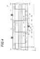
- FIG. 4 is an enlarged view of a part of FIG.
- FIG. 5 is a front view showing the structure of the main part of the head.
- FIG. 6 is a side view showing the structure of the main part of the head. *
- the inkjet head 200 is configured by connecting a plurality of head modules 210 in a line.
- Each head module 210 has the same structure, and is arranged in a row on the base frame 212 to constitute one inkjet head 200.
- the nozzle arrangement direction (nozzle row direction) of the inkjet head 200 is the X direction
- the direction orthogonal to the nozzle surface is the Z direction
- the direction parallel to the nozzle surface and orthogonal to the X direction is the Y direction.
- the X direction, the Y direction, and the Z direction are orthogonal to each other. *
- the head module 210 is a so-called short head, and can record an image having a predetermined print width as a single unit. By connecting a plurality of head modules 210 along the direction of the nozzle row (the direction perpendicular to the transport direction of the paper P), one long head is configured.
- FIG. 7 is a front view of the head module.
- FIG. 8 is a rear view of the head module.
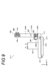
- FIG. 9 is a side sectional view of the head module.
- the head module 210 includes an inkjet head 214 that ejects ink and a bracket 216 that attaches the inkjet head 214 to the base frame 212.
- the inkjet head 214 is mainly composed of a head main body 218 and an electrical / piping section 220. *
- the head main body 218 has a rectangular plate shape.
- the head main body 218 has a nozzle surface 222 on the lower surface portion.
- the nozzle surface 222 has a belt-like nozzle formation region 222A at the center.
- the nozzle formation region 222A has a certain width and is formed along the X direction.
- the nozzle N is formed in this nozzle formation region 222A.
- the nozzles N are arranged in a two-dimensional matrix. Specifically, they are arranged at a constant pitch along the X direction and at a constant pitch along a direction inclined by a predetermined angle with respect to the X direction.
- the arrangement direction of the nozzles N (the direction of the nozzle row) is the X direction.
- the nozzles N may be arranged in a line along the X direction.
- the electrical / pipe section 220 is an assembly of pipes, circuit boards, and the like, and is provided on the top of the head main body 218. *
- the bracket 216 is formed in an L shape including a horizontal portion 224 and a vertical portion 226. *
- the horizontal portion 224 functions as an attachment portion for the inkjet head 214.
- the vertical part 226 functions as an attachment part to the base frame 212. *
- the horizontal part 224 has a rectangular plate shape.
- the horizontal portion 224 is formed in a shape (rectangular shape) substantially the same as the outer shape of the head main body portion 218 of the inkjet head 214.
- the ink jet head 214 has the head main body 218 attached to the lower surface of the horizontal portion 224.
- the horizontal portion 224 is provided with an opening 224 ⁇ / b> A for passing the electrical / piping portion 220 of the inkjet head 214. *
- the vertical portion 226 also has a plate shape.
- the vertical part 226 is disposed perpendicular to the horizontal part 224, joined to one end of the horizontal part 224, and integrated with the horizontal part 224. *
- the vertical portion 226 includes a vertical portion main body 226A formed with substantially the same width as the horizontal portion 224, a pair of first protruding portions 226B formed to protrude from both sides of the vertical portion main body 226A in the X direction, and a pair of A pair of second projecting portions 226C formed by projecting further in the X direction from the first projecting portion 226B is configured.
- the vertical portion 226 is provided with a head module Y-direction positioning means serving as a reference for positioning in the Y direction when the head module 210 is attached to the base frame 212, and a head module Z-direction positioning means serving as a reference for positioning in the Z direction.
- a part of the X direction attachment position adjusting means for fine adjustment of the attachment position in the X direction is provided.
- the head module Y direction positioning means includes two head module Y direction fixed contact members 234 that constitute the head module Y direction positioning member, and one head module Y direction movable contact member 236 that also constitutes the head module Y direction positioning member. Consists of. *
- the two head module Y-direction fixed contact members 234 are provided on the second overhanging portion 226C of the vertical portion 226.
- the head module Y-direction fixed contact member 234 is formed of a hard sphere (a rigid sphere).
- the head module Y-direction fixed contact member 234 is inserted into a hole (not shown) formed in the second overhang portion 226C, and the inner surface of the second overhang portion 226C (when the head module 210 is attached to the base frame 212) A part of the surface facing the base frame 212).
- the head module Y-direction movable contact member 236 is provided on the vertical portion main body 226A of the vertical portion 226.
- the head module Y-direction movable contact member 236 is formed of a rigid sphere, and is inserted into the head module Y-direction movable contact member insertion hole 238 formed in the vertical portion main body 226A, and is provided in the vertical portion main body 226A.
- the head module Y-direction movable contact member insertion hole 238 is formed along the Y direction and is formed so as to penetrate from the outer surface to the inner surface of the vertical portion main body 226A.
- the head module Y-direction movable contact member 236 is inserted into the head module Y-direction movable contact member insertion hole 238 so as to protrude from the inner surface of the vertical portion main body 226A.
- the head module Y-direction movable contact member insertion hole 238 is formed by reducing the diameter of the inner surface side of the vertical portion main body 226A so that the head module Y-direction movable contact member 236 does not fall off.
- the head module Y-direction movable contact member insertion hole 238 is a screw hole, and the head module Y-direction movable contact member position adjusting screw 240 is screwed together.
- the head module Y-direction movable contact member position adjusting screw 240 is constituted by a so-called potato screw (a screw head having the same size as the screw portion).
- the head module Y-direction fixed contact member 234 and the head module Y-direction movable contact member 236 are fixed contact base frame Y provided on the base frame 212 side when the head module 210 is attached to the base frame 212.
- the direction positioning member 290 and the movable contact base frame Y direction positioning member 292 are brought into contact with each other. As a result, the head module 210 is positioned in the Y direction with respect to the base frame 212.
- the head module Z direction positioning means is composed of a pair of head module Z direction contact members 242 constituting a head module Z direction positioning member.
- the pair of head module Z direction contact members 242 are provided on the first overhanging portion 226 ⁇ / b> B of the vertical portion 226.
- the head module Z direction contact member 242 is formed of a hard sphere.
- the head module Z-direction contact member 242 is inserted into the head module Z-direction contact member insertion hole 244 formed in the first overhang portion 226B, and is provided in the first overhang portion 226B.
- the head module Z-direction contact member insertion hole 244 is formed along the Z direction and is formed so as to penetrate from the lower surface to the upper surface of the first overhang portion 226B.
- the head module Z-direction contact member 242 is inserted into the head module Z-direction contact member insertion hole 244, and a part thereof is provided so as to protrude from the upper surface of the first overhang portion 226B.
- the head module Z direction contact member insertion hole 244 is formed by reducing the diameter of the upper surface side of the first overhanging portion 226B so that the head module Z direction contact member 242 does not fall off.
- the head module Z direction contact member insertion hole 244 is configured by a screw hole.
- a head module Z direction contact member position adjusting screw 246 is screwed into the head module Z direction contact member insertion hole 244.
- the head module Z-direction contact member position adjusting screw 246 is constituted by a so-called potato screw.
- the head module Z-direction contact member 242 comes into contact with a base frame Z-direction contact member 294 provided on the base frame 212 side when the head module 210 is attached to the base frame 212. As a result, the head module 210 is positioned in the Z direction with respect to the base frame 212.
- the pair of head module Z-direction contact members 242 are set so that the installation interval (X-direction installation interval) is longer than the print area width of the inkjet head 214 (total nozzle row length). Is preferred. Thereby, the stability at the time of sitting increases and the positioning precision of a Z direction can be improved. *
- the installation interval (installation interval in the X direction) is longer than the print area width (total nozzle row length) of the inkjet head 214. It is preferable to set so. Thereby, the stability at the time of sitting increases and the positioning accuracy in the Y direction can be improved.
- the X direction attachment position adjusting means (attachment position adjusting means) is mainly composed of an eccentric roller 248, a plunger 250, and an X direction positioning reference pin (positioning reference pin) 296.
- the eccentric roller 248 and the plunger 250 are provided on the head module 210, and the X-direction positioning reference pin 296 is provided on the base frame 212.
- the eccentric roller 248 and the plunger 250 are disposed on the inner surface side of the vertical portion main body 226A.
- the eccentric roller 248 and the plunger 250 are arranged to face each other with a constant interval.
- the eccentric roller 248 includes a shaft portion 248A and a roller portion 248B.
- the shaft portion 248A functions as a rotation shaft for rotating the roller portion 248B, and is eccentrically connected to the roller portion 248B. For this reason, when the shaft portion 248A is rotated, the roller portion 248B is eccentrically rotated.
- the shaft portion 248A of the eccentric roller 248 is constituted by a male screw.
- the shaft portion 248A is inserted into the eccentric roller mounting hole 252 of the vertical portion main body 226A.
- the eccentric roller mounting hole 252 is a screw hole and is formed in parallel with the Y direction.
- the eccentric roller mounting hole 252 is formed to penetrate from the outer surface side to the inner surface side of the vertical portion main body 226A.
- the eccentric roller 248 is attached to the vertical portion main body 226A by screwing the shaft portion 248A into the eccentric roller attachment hole 252.
- a groove (+ or ⁇ groove) for rotating the shaft portion 248A with a screw driver is formed on the end surface of the shaft portion 248A of the eccentric roller 248.
- the eccentric roller 248 attached to the vertical portion main body 226A rotates by rotating the shaft portion 248A using a screw driver, whereby the roller portion 248B is eccentric. *
- a plate spring 254 is pressed against the roller portion 248B.
- the leaf spring 254 is disposed on the inner surface side of the vertical portion main body 226A.
- the leaf spring 254 is brought into contact with the peripheral surface of the roller portion 248B and presses the roller portion 248B in the axial direction.
- the roller portion 248 ⁇ / b> B is given a certain resistance to rotation by the leaf spring 254.
- the plunger 250 functions as X direction urging means.
- the plunger 250 is disposed along the X direction, and the tip (pressing portion) is disposed to face the eccentric roller 248. *
- the eccentric roller 248 and the plunger 250 are arranged to face each other with a constant interval.
- the X-direction positioning reference pin 296 provided on the base frame side is fitted between the eccentric roller 248 and the plunger 250 and is sandwiched between the eccentric roller 248 and the plunger 250.
- the plunger 250 presses the X-direction positioning reference pin 296 in the X direction.
- the head module 210 is biased in the X direction.
- the eccentric roller 248 is rotated in this state, the head module 210 moves in the X direction according to the rotation amount.
- a guide groove 256 for attaching the bracket 216 to the base frame 212 is further formed in the vertical portion 226 of the bracket 216.
- the guide groove 256 is formed in the vertical portion main body 226A of the vertical portion 226, and is formed with a predetermined width and a predetermined depth vertically downward (Z direction) from the upper surface portion of the vertical portion main body 226A.
- the guide groove 256 is fitted with a pair of Y-direction guide posts 276 provided on the base frame side when the bracket 216 is attached to the base frame 212. For this reason, the width of the guide groove 256 is formed to be substantially the same as the width (diameter) of the Y direction guide post 276. Thereby, interference with the adjacent head module 210 can be prevented.
- the guide groove 256 has an arc-shaped enlarged diameter portion 256 ⁇ / b> A formed at the tip (lower end) and substantially the center.
- the enlarged diameter portion 256A of the guide groove 256 is provided to support the head module 210 so that the head module 210 is movable, so that the formation position is formed corresponding to the Y-direction guide post 276, and the head module 210 is attached to the base frame.
- the Y-direction guide post 276 is formed so as to be accommodated at substantially the center position thereof.
- the enlarged diameter portion 256A is formed so as to form a circle centered on the axis of the Y-direction guide post 276. This circle is formed larger than the diameter of the Y direction guide post 276.
- the head module 210 when the head module 210 is attached to the base frame 212, the head module 210 can be supported so as to be movable within a predetermined range. Further, when the head module 210 is attached to the base frame 212, the head module 210 can be attached without causing backlash.
- a pair of notches 258A and 258B are formed on the inner wall surface of the guide groove 256.
- the bracket 216 is attached to the base frame 212, the pair of notches 258A and 258B are engaged with the locking bar 288 of the Z-direction hanging rod 278 provided on the base frame side.
- the bracket 216 is locked to the base frame 212 when the locking bar 288 of the Z-direction hanging rod 278 is engaged with the notches 258A and 258B.
- the notches 258A and 258B are formed at positions facing the inner wall surface of the guide groove 256, and are formed with a predetermined depth on the inner surface side and the outer surface side of the vertical portion 226 of the bracket 216, respectively. That is, one notch portion 258A is formed on the outer surface side of the vertical portion 226, and the other notch portion 258B is formed on the inner surface side.
- a magnet 260 for detecting the amount of displacement (movement amount) of the head module 210 when the head module 210 is attached to the base frame 212 is provided in the vertical portion 226 of the bracket 216.
- This magnet 260 constitutes a displacement detection means together with a magnetic sensor 298 provided on the base frame 212 side.
- the magnet 260 is disposed to face the magnetic sensor 298 provided on the base frame 212 side.
- the head module 210 is configured as described above. *
- FIG. 10 is a front view showing the structure of the main part of the base frame.
- FIG. 11 is a side sectional view showing the structure of the main part of the base frame. *
- the base frame 212 mainly includes an upper frame portion 270 and a pair of lower frame portions 272A and 272B. *
- the upper frame part 270 has a rectangular plate shape.
- the upper frame part 270 is disposed horizontally (parallel to the XY plane).
- the pair of lower frame portions 272A and 272B have a rectangular plate shape.
- the pair of lower frame parts 272A and 272B are arranged perpendicularly (parallel to the XZ plane) to the lower part of the upper frame part 270 with a constant interval.
- the pair of lower frame portions 272A and 272B function as attachment portions for attaching the head module 210.
- the head module 210 is alternately attached to the pair of lower frame portions 272A and 272B. That is, if one lower frame portion 272A is a first lower frame (first mounting portion) and the other lower frame portion 272B is a second lower frame (second mounting portion), the first head module 210 is the first head module 210.
- the second head module 210 which is attached to the lower frame portion 272A and arranged next to the lower frame portion 272A, is attached to the second lower frame portion 272B.
- the third head module 210 arranged next to the second head module 210 is attached to the first lower frame portion 272A, and the fourth head module arranged next to the second head module 210 is attached to the second lower frame. It is attached to the part 272B. In this manner, the head module 210 is alternately attached to the first lower frame portion 272A and the second lower frame portion 272B.
- the base frame 212 is provided with a head module support means for supporting the head module 210.
- the head module support means is prepared for each head module.
- the installation interval (X-direction installation interval) of the head module support means coincides with the installation interval (X-direction installation interval) of the head module 210 attached to each lower frame portion 272A, 272B.
- the head module support means includes a pair of Y direction guide posts 276 and a Z direction hanging rod 278. *
- the pair of Y-direction guide posts 276 are arranged in parallel in the vertical direction (Z direction) with a constant interval.
- the Y direction guide post 276 is formed in a cylindrical shape.
- the Y-direction guide post 276 has a flange portion 276A at the top.
- the Y-direction guide post 276 is provided so as to protrude from the outer surface of the lower frame portions 272A and 272B, and is disposed in parallel with the Y direction.
- the width (diameter) of the Y direction guide post 276 is formed to be approximately the same as the width of the guide groove 256. *
- the guide groove 256 formed in the vertical portion 226 of the bracket 216 is fitted into the pair of Y direction guide posts 276. Since the width (diameter) of the Y-direction guide post 276 is formed substantially the same as the width of the guide groove 256, the Y-direction guide post 276 can be attached without rattling.
- Each of the pair of Y direction guide posts 276 is provided with a Y direction pressing plate 280.
- the Y-direction pressing plate 280 is formed in a ring shape.
- the Y-direction pressing plate 280 is provided on the Y-direction guide post 276 with the Y-direction guide post 276 inserted through the inner periphery thereof. *
- Each of the pair of Y direction guide posts 276 is provided with a Y direction pressing spring 282.
- the Y-direction pressing spring 282 is provided on the Y-direction guide post 276 with the Y-direction guide post 276 inserted through the inner periphery thereof.
- the Y-direction pressing spring 282 is disposed between the flange portion 276 ⁇ / b> A of the Y-direction guide post 276 and the Y-direction pressing plate 280.
- the pair of Y-direction guide posts 276 are fitted into the guide grooves 256.
- the Y-direction pressing plate 280 engages with the vertical portion 226 of the bracket 216. Since the Y direction pressing plate 280 is urged in the Y direction by the Y direction pressing spring 282, the head module 210 is pressed toward the base frame 212 by the Y direction pressing plate 280.
- the pair of Y-direction guide posts 276 are arranged at regular intervals in the vertical direction as described above, but the Y-direction pressing springs 282 provided in each Y-direction guide post 276 have different urging forces, that is, Different spring constants are used.
- the Y-direction pressing spring 282 provided in the lower Y-direction guide post 276 has a larger spring constant than the Y-direction pressing spring 282 provided in the upper Y-direction guide post 276.
- the pressing force by the Y-direction pressing plate 280 provided on the lower Y-direction guide post 276 is larger than the pressing force by the Y-direction pressing plate 280 provided on the upper Y-direction guide post 276.
- the X-direction attachment position adjusting means is provided in the vicinity of the lower Y-direction guide post 276, and therefore the Y-direction provided in the lower Y-direction guide post 276.
- the spring constant of the pressing spring 282 is larger than the spring constant of the Y-direction pressing spring 282 provided in the upper Y-direction guide post 276, but the X-direction mounting position adjusting means is close to the upper Y-direction guide post 276.
- the spring constant of the Y-direction pressing spring 282 provided in the upper Y-direction guide post 276 is made larger than the spring constant of the Y-direction pressing spring 282 provided in the lower Y-direction guide post 276.
- the spring constant of the Y-direction pressing spring 282 of the Y-direction guide post 276 installed closer to the X-direction mounting position adjusting means is larger than the spring constant of the Y-direction pressing spring 282 of the Y-direction guide post 276 on the other side. To do. Thereby, the inclination of the head module 210 at the time of adjusting the attachment position in the X direction can be prevented.
- the Z direction hanging rod 278 is formed in a cylindrical shape.
- the Z-direction hanging rod 278 has a knob portion 278A at the top.
- the Z direction hanging rod 278 is arranged in parallel with the Z direction.
- a Z-direction hanging rod insertion hole 284 for attaching the Z-direction hanging rod 278 is formed in the upper frame portion 270.
- the Z-direction hanging rod insertion hole 284 is formed along the Z direction and is formed to penetrate from the upper surface portion of the upper frame portion 270 to the lower surface portion.
- the Z-direction hanging rod 278 is inserted into the Z-direction hanging rod insertion hole 284 and attached to the upper frame portion 270. *
- the Z-direction hanging rod 278 attached to the upper frame portion 270 is disposed in front of the outer surface of the lower frame portions 272A and 272B.
- the Z-direction hanging rod 278 is disposed on the same straight line as the pair of Y-direction guide posts 276 and is disposed above the pair of Y-direction guide posts 276. Therefore, when the head module 210 is attached to the base frame 212, the Z-direction hanging rod 278 is accommodated in the guide groove 256. *
- the Z-direction hanging rod 278 is provided with a Z-direction pressing spring 286.
- the Z-direction pressing spring 286 is provided on the Z-direction hanging rod 278 with the Z-direction hanging rod 278 inserted through the inner periphery thereof.
- the Z-direction pressing spring 286 is provided between the knob portion 278 ⁇ / b> A of the Z-direction hanging rod 278 and the upper frame portion 270.
- the Z-direction hanging rod 278 is biased upward by the biasing force of the Z-direction pressing spring 286 (biased in the direction of pulling up toward the upper frame portion 270).
- the Z-direction hanging rod 278 is provided with a locking bar 288 at the tip (lower end).
- the locking bar 288 is provided so as to protrude left and right from the tip of the Z-direction hanging rod 278 (provided perpendicular to the axial direction of the Z-direction hanging rod 278).
- the locking bar 288 is formed longer than the width of the guide groove 256.
- the locking bar 288 is fitted into the notches 258A and 258B formed in the guide groove 256 on the head module 210 side to lock the head module 210. *
- the locking bar 288 is fitted into A and 258B by rotating the Z-direction hanging rod 278. That is, as described above, the lock bar 288 is formed to be longer than the width of the guide groove 256, so that the head module 210 is placed in the state where it is directed in the same direction as the width direction (X direction) of the guide groove 256. When attached to the frame 212, the locking bar 288 comes into contact with the inlet portion (upper end portion) of the guide groove 256, and the head module 210 cannot be attached.
- the lock bar 288 is positioned so as not to contact the inner wall surface of the guide groove 256, and the head module 210 is attached to the base frame 212 in this state. Then, when the head module 210 is attached to the base frame 212 and the locking bar 288 is located at the position where the notches 258A and 258B are formed, the Z-direction hanging rod 278 is rotated. As a result, the locking bar 288 fits into the notches 258A and 258B.
- the base frame 212 includes a base frame Y-direction positioning means for positioning in the Y direction when the head module 210 is attached to the base frame 212, and a base frame Z-direction positioning means for positioning in the Z direction. It is done. *
- the base frame Y direction positioning means includes two fixed contact base frame Y direction positioning members 290 constituting the base frame Y direction positioning member and one movable contact base frame Y direction which also constitutes the base frame Y direction positioning member. And a positioning member 292. *
- the two fixed contact base frame Y direction positioning members 290 are each composed of a pin having rigidity (for example, a pin made of stainless steel), and has a higher hardness than the head module Y direction fixed contact member 234.
- the two fixed contact base frame Y-direction positioning members 290 are provided so as to protrude downward (downward in the Z direction) from the lower surface portions of the lower frame portions 272A and 272B, respectively.
- the two fixed contact base frame Y direction positioning members 290 are provided at the same interval as the installation interval of the two head module Y direction fixed contact members 234 provided on the head module 210 side, and the head module 210 is attached to the base frame 212.
- the two head module Y-direction fixed contact members 234 are provided at positions where they contact the peripheral surface. That is, the two fixed contact base frame Y direction positioning members 290 are provided corresponding to the two head module Y direction fixed contact members 234 provided on the head module 210 side.
- the movable contact base frame Y-direction positioning member 292 is configured with a rigid pin (for example, a stainless steel pin) and is configured with higher hardness than the head module Y-direction movable contact member 236.
- the movable contact base frame Y-direction positioning member 292 is housed in a recess formed on the outer surface of the lower frame portions 272A, 272B and disposed on the lower frame portions 272A, 272B.
- the movable contact base frame Y-direction positioning member 292 is arranged in parallel with the Y direction.
- the movable contact base frame Y direction positioning member 292 is provided at a position where the head module Y direction movable contact member 236 on the head module 210 side comes into contact with the front end surface thereof. That is, the movable contact base frame Y-direction positioning member 292 is provided corresponding to the head module Y-direction movable contact member 236 provided on the head module 210 side.
- the head module 210 when the head module 210 is attached to the base frame 212, the head module 210 is pressed toward the base frame 212 by the Y-direction pressing plate 280 provided in the Y-direction guide post 276. Accordingly, when the head module 210 is attached to the base frame 212, the two head module Y-direction fixed contact members 234 provided on the head module 210 side become the two fixed contact base frame Y-directions provided on the base frame 212 side. It is pressed against the positioning member 290. The head module Y-direction movable contact member 236 provided on the head module 210 side is pressed and brought into contact with the movable contact base frame Y-direction positioning member 292 provided on the base frame 212 side. Thereby, the head module 210 attached to the base frame 212 is positioned in the Y direction with respect to the base frame 212. *
- the fixed contact base frame Y direction positioning member 290 is configured with higher hardness than the head module Y direction fixed contact member 234, and the movable contact base frame Y direction positioning member 292 is formed of the head module Y.
- the directional movable contact member 236 is configured with higher hardness.
- a material having a high hardness can be used, or a method for increasing the hardness by applying a surface treatment can be employed.
- Base frame Z direction positioning means for positioning the head module 210 in the Z direction with respect to the base frame 212 includes a pair of base frame Z direction contact members 294. *
- the pair of base frame Z-direction contact members 294 are configured by rigid pins (for example, stainless steel pins) and are formed with higher hardness than the head module Z-direction contact member 242.
- the pair of base frame Z-direction contact members 294 are provided so as to protrude from the outer surfaces of the lower frame portions 272A and 272B, respectively, and are disposed in parallel with the Y direction.
- the pair of base frame Z-direction contact members 294 are provided at the same interval as the installation interval of the pair of head module Z-direction contact members 242 provided on the head module 210 side, and when the head module 210 is attached to the base frame 212,
- the head module Z-direction contact member 242 is provided at a contact position. That is, the pair of base frame Z-direction contact members 294 are provided corresponding to the head module Z-direction contact member 242 provided on the head module 210 side.
- the head module 210 when the head module 210 is attached to the base frame 212, the head module 210 is biased upward by the action of the Z-direction pressing spring 286 provided on the Z-direction hanging rod 278. Therefore, when the head module 210 is attached to the base frame 212, the pair of head module Z-direction contact members 242 provided on the head module 210 abut on the pair of base frame Z-direction contact members 294 provided on the base frame 212. Is done. As a result, the head module 210 is positioned in the Z direction with respect to the base frame 212. *
- the base frame Z-direction contact member 294 is formed with higher hardness than the head module Z-direction contact member 242. Thereby, the position stability at the time of positioning can be improved, and the repeatability when the head module 210 is replaced can be improved.
- a material having a high hardness can be used, or a method for increasing the hardness by applying a surface treatment can be employed.
- the base frame 212 is provided with an X-direction positioning reference pin 296 that is a constituent member of the X-direction attachment position adjusting means.
- the X-direction positioning reference pin 296 is configured by a rigid pin (for example, a stainless steel pin), and is provided to protrude downward (downward in the Z direction) from the lower surface of the lower frame portions 272A and 272B.
- the X-direction positioning reference pin 296 is disposed at a position where the X-direction positioning reference pin 296 is fitted between the eccentric roller 248 provided on the head module 210 side and the plunger 250 when the head module 210 is attached to the base frame 212. *
- the X-direction positioning reference pin 296 is inserted between the eccentric roller 248 and the plunger 250 and is sandwiched between them.
- the eccentric roller 248 is rotated in this state, the head module 210 is displaced in the X direction with respect to the base frame 212.
- the base frame 212 is provided with a magnetic sensor 298 that constitutes a displacement amount detecting means together with the magnet 260 provided on the head module 210 side.
- the magnetic sensor 298 is provided in the lower frame portions 272A and 272B.
- the lower frame portions 272A and 272B are provided with a magnetic sensor mounting portion 300 at a predetermined position.
- the magnetic sensor 298 is attached to the magnetic sensor mounting part 300.
- the magnetic sensor 298 attached to the magnetic sensor mounting portion 300 is disposed at a position facing the magnet 260 provided on the head module 210 side.
- the head module 210 attached to the base frame 212 is displaced in the X direction by the X direction attachment position adjusting means, the amount of displacement is detected by the magnetic sensor 298. Information on the amount of displacement detected by the magnetic sensor 298 is output to the system controller 100.
- the base frame 212 is configured as described above. *
- the material of the base frame 212 is not particularly limited, but it is preferable to use a material that is not easily affected by heat so that the head module 210 can be attached with high accuracy. Specifically, it is preferable to form a material having a linear expansion coefficient of 10 ppm / ° C. or lower, which is lower than the iron-based linear expansion coefficient (about 15 ppm / ° C.). Thereby, it is possible to prevent the mounting position of the head module 210 from being changed due to the influence of heat. As such a material, for example, ceramics, invar, and super invar can be used. *
- the base frame 212 is provided with the head module support means, and the head module 210 is attached to the base frame 212 using the head module support means.
- the head module support means is alternately provided on the pair of lower frame portions 272A and 272B. Therefore, the head module 210 is alternately attached to the pair of lower frame portions 272A and 272B. In addition, since the attachment method itself is the same everywhere, the case where it attaches to the lower frame part 272A is demonstrated here. *
- the head module 210 is attached to the base frame 212 by an operation of pushing it upward from the bottom of the base frame 212.
- the horizontal portion 224 of the bracket 216 of the head module 210 is set in a posture parallel to the upper frame portion 270 of the base frame 212 at a position below the base frame 212. Further, the vertical portion 226 of the bracket 216 is set in a posture parallel to the lower frame portion 272A of the base frame 212. In this state, the position of the guide groove 256 formed in the bracket 216 of the head module 210 is aligned with the position of the Y-direction guide post 276 provided in the lower frame portion 272A of the base frame 212.
- the head module 210 is pushed up toward the base frame 212 so that the Y-direction guide posts 276 fit into the guide grooves 256.
- the head module 210 is pushed up vertically using the Y-direction guide post 276 as a guide. Thereby, blurring and rattling at the time of attachment can be prevented, and the head module 210 can be prevented from coming into contact with other members (such as the attached head module 210).
- the Z-direction hanging rod 278 is provided with a locking bar 288.
- the locking bar 288 is positioned at the unlocking position so that the locking bar 288 does not contact the inner wall surface of the guide groove 256. Accordingly, it is possible to prevent the lock bar 288 from coming into contact with the entrance portion of the guide groove 256 and hindering the movement of the head module 210.
- the pair of head module Z-direction contact members 242 provided on the bracket 216 of the head module 210 are paired with the pair of base frames provided on the base frame 212. It abuts on the Z-direction contact member 294.
- the pair of head module Z-direction contact members 242 are brought into contact with the pair of base frame Z-direction contact members 294 provided on the base frame 212, the pair of head modules 210 are formed in the guide grooves 256 of the head module 210.
- the notches 258 ⁇ / b> A and 258 ⁇ / b> B are located at the installation position of the lock bar 288 provided on the Z-direction hanging rod 278.
- the Z-direction hanging rod 278 is rotated, and the lock bar 288 is positioned at the lock position.
- the locking bar 288 fits into the notches 258A and 258B, and the locking bar 288 is locked to the ceiling surface of the inner periphery of the notches 258A and 258B.
- the head module 210 is attached to the base frame 212 in a state of being suspended by the Z-direction suspension rod 278.
- the Z-direction hanging rod 278 is provided with a Z-direction pressing spring 286. Therefore, when the Z-direction suspension rod 278 is engaged, the head module 210 is pushed upward by the action of the Z-direction pressing spring 286. As a result, the pair of head module Z direction contact members 242 provided on the head module 210 abut on the pair of base frame Z direction contact members 294 provided on the base frame 212. As a result, the head module 210 is positioned in the Z direction with respect to the base frame 212. *
- a pair of Y direction guide posts 276 fitted in the guide groove 256 is provided with a Y direction pressing spring 282.
- the Y direction pressing spring 282 presses the head module 210 toward the base frame 212 via the Y direction pressing plate 280.
- the head module Y-direction fixed contact member 234 and the head module Y-direction movable contact member 236 provided on the head module 210 are connected to the base frame Y-direction positioning member 290 for fixed contacts provided on the base frame 212 and the movable contact.
- the base frame Y direction positioning member 292 is pressed against and abutted on.
- the head module 210 is positioned in the Y direction with respect to the base frame 212. *
- the head module Z-direction contact member 242 When the head module Z-direction contact member 242 is brought into contact with the base frame Z-direction contact member 294, the Y-direction guide post 276 is accommodated in the enlarged diameter portion 256A formed in the guide groove 256. Thereby, the head module 210 is attached to the base frame 212 in a state displaceable in the X direction.
- the head module Z-direction contact member 242 and the head module Y-direction movable contact member 236 can be adjusted in position, but this position adjustment is preferably performed in advance (for example, performed at the time of factory shipment). *
- the head module 210 is attached to the base frame 212. This operation is performed for all the head modules 210. As described above, since the head modules 210 are alternately attached to the base frame 212, the attachment is performed alternately. *
- the attachment is preferably performed in order from one end of the base frame 212 to the other.
- the first head module 210 (the head module 210 to be attached first) is attached in accordance with the median value of the adjustment range of the displacement amount in the X direction. Accordingly, it is possible to reduce the risk that the subsequent mounting position of the head module 210 is out of the adjustment range, and it is possible to prevent the adjustment range from being unnecessarily large.
- the base frame 212 to which the head module 210 is attached is held by a predetermined holder provided in the ink jet recording apparatus 10 and mounted on the ink jet recording apparatus 10.
- the head module 210 is attached to the base frame 212 by the above-described attaching operation. However, this attachment is a rough attachment (temporary attachment). Thereafter, the interval between the head modules adjacent to each other is adjusted precisely so that no gap is generated in the nozzle row at the joint of the head modules 210. That is, the head module 210 is positioned. Hereinafter, a method for positioning the head module 210 will be described. *
- the positioning of the head module 210 detects the relative positional relationship between the head modules 210 attached to the base frame 212, and based on the detection result, the interval between the head modules 210 falls within an allowable range. This is done by adjusting the mounting position in the X direction.
- the relative positional relationship between the head modules 210 attached to the base frame 212 is detected by recording an image of a predetermined test pattern on a sheet with the inkjet head 200 to which the head module 210 is assembled. . That is, the inkjet head 200 with the head module 210 assembled is mounted on the inkjet recording apparatus 10, an image of a predetermined test pattern is recorded on the paper P, and the relative positional relationship of each head module 210 is determined from the recorded image. To detect. *
- Reading of the image recorded on the paper P is performed by the inline sensor 58.
- the system controller 100 acquires the image data of the test pattern read by the inline sensor 58, processes the obtained image data, and detects the relative positional relationship between the head modules 210. For example, as shown in FIG. 14, the distance between dots ejected by the reference nozzle N in each head module 210 is measured on the image data, and the relative positional relationship (adjacent heads) of each head module 210 is measured. The interval ⁇ ) of the module 210 is detected.
- This process is performed by the system controller 100 executing a predetermined control program.
- the system controller 100 functions as position detection means and position information acquisition means for detecting the relative position of each head module 210 by executing this control program. *
- each head module 210 After the relative positional relationship of each head module 210 is detected, the attachment position of each head module 210 is finely adjusted using the X direction attachment position adjusting means. That is, the position of each head module 210 in the X direction is adjusted so that the interval between adjacent head modules 210 is within a preset allowable range.
- the position adjustment in the X direction by the X direction attachment position adjusting means is performed by rotating the eccentric roller 248 provided in each head module 210.
- the eccentric roller 248 is rotated using a screw driver. That is, since a groove for a screw driver is formed on the end surface of the shaft portion 248A of the eccentric roller 248, the tip of the screw driver is fitted in the groove, and the shaft portion 248A is rotated by the screw driver.
- the eccentric roller 248 is rotated.
- the eccentric roller 248 rotates eccentrically.
- the head module 210 moves in the X direction with reference to the X direction positioning reference pin 296.
- the head module 210 moves in the X direction, the amount of displacement is detected by the magnetic sensor 298. Information on the detected displacement amount is output to the system controller 100.
- the system controller 100 outputs information on the obtained displacement amount to the display unit 132.
- the operator rotates the eccentric roller 248 by a necessary amount based on the displacement amount information displayed on the display unit 132.
- the correction amount of each head module 210 is determined from the relative positional relationship of each head module 210. That is, the correction amount of the mounting position of each head module 210 is determined so that the interval between adjacent head modules 210 is within a preset allowable range.
- the system controller 100 acquires information on the relative position of each head module 210 (head module position information), and calculates a correction amount for keeping the interval between adjacent head modules 210 within an allowable range. Information on the calculated correction amount of the mounting position of each head module 210 is displayed on the display unit 132 as an instruction unit. The operator moves the head module 210 and adjusts the mounting position of the head module 210 based on the correction amount information displayed on the display unit 132. *
- the correction amount is calculated when the system controller 100 executes a predetermined control program. By executing this control program, the system controller 100 functions as a correction amount calculating means.
- the mounting and position adjustment (positioning) of the head module 210 is completed by the series of operations described above.
- the case where all the head modules 210 are attached to the base frame 212 has been described.
- the attachment is performed in the same procedure and the position is adjusted.
- the head module 210 is removed as follows. *
- the head module 210 is attached in a state of being suspended by the base frame 212 while being locked to the locking bar 288 of the Z-direction hanging rod 278.
- the lock bar 288 is disengaged. That is, the Z-direction hanging rod 278 is rotated to move the lock bar 288 to the unlock position.
- the lock bar 288 is disengaged from the notches 258A and 258B, and the engagement between the head module 210 and the lock bar 288 is released.
- the head module 210 is pulled downward.
- the head module 210 is removed from the base frame 212.
- the pair of Y-direction guide posts 276 serve as guides, so that the head module 210 can be removed without contacting the other head modules 210.
- each head module 210 is individually attached to the base frame 212, and individually.
- the mounting position is adjusted. Thereby, attachment and position alignment can be performed easily.
- the head module is highly accurate. You can connect each other. Further, the adjustment width can be sufficiently secured, and the component tolerance can be suppressed low. Thereby, manufacturing cost can be held down.
- the inkjet head 200 has a structure in which the head modules 210 are alternately attached to the base frame 212 when the head modules 210 are attached to the base frame 212.
- interval of the adjacent head module 210 can be taken widely. Since the distance between the adjacent head modules 210 can be widened, the distance between the positioning contacts (the distance between the head module Z-direction contact members 242) can be widened (print area width (total nozzle row). Can be taken wider than length).). Thereby, the precision of the rotation direction of the head module 210 can be taken high, and the head module 210 can be attached with high precision in a more stable state. For example, when the print area width l of the head module 210 is 40 mm, the distance between the contact points for positioning is 70 mm. *
- the head module 210 is positioned in the X direction so that the distance between adjacent head modules 210 is within an allowable range. This is done by adjusting the position.
- the head unit 56 as a whole can be positioned with higher accuracy.
- each head module of each inkjet head 200 is set so that the interval between adjacent head modules 210 is within an allowable range based on information on the relative position of the head module 210 of each inkjet head 200 (head module position information). While adjusting the attachment position of 210, the attachment position of each head module 210 of each inkjet head 200 is adjusted so that the printing area width L of each inkjet head 200 may become the same. As a result, the print area width L of each inkjet head 200 matches, and a high-quality image can be recorded.
- the inkjet recording apparatus 10 ejects cyan (C) ink droplets, an inkjet head 200C that ejects magenta (M) ink droplets, and a yellow (Y) ink droplet.
- Ink jet head 200Y, and inkjet head 200K that ejects black (K) ink droplets, cyan ink jet head 200C, magenta ink jet head 200M, yellow ink jet head 200Y, and black ink jet
- the head modules 210 of the inkjet heads 200C, 200M, 200Y, and 200K are positioned. *
- the print area width L in each inkjet head 200 can be obtained from information on the relative position of the head module 210 as shown in FIG. 14, for example. That is, the print area width L of the inkjet head 200 can be obtained from the information of the print area width l of each head module 210 (the length of the nozzle row of the head module 210) and the information of the interval ⁇ of each head module 210. (The print area width l of each head module 210 is known). *
- each head module 210 in the head (for example, the head module disposed at one end of the inkjet head 200) from the information of the print area width l of each head module 210 and the information of the interval ⁇ of each head module 210.
- the position of each head module 210 with respect to 210 can also be obtained.
- each inkjet head 200 when adjusting the position of the head module 210 of each inkjet head 200, the adjacent heads are utilized using information on the relative position of the head module 210 of each inkjet head 200 (head module position information).
- head module position information information on the relative position of the head module 210 of each inkjet head 200
- the mounting position of each head module 210 of each inkjet head 200 is adjusted so that the interval between the modules 210 is within an allowable range and the print area width L of each inkjet head 200 is the same.
- the relative position of each head module 210 attached to the base frame 212 is detected by recording an image of a predetermined test pattern on a sheet with the inkjet head 200 to which the head module 210 is assembled. Is called. That is, an image of a predetermined test pattern is recorded on the paper P, the image recorded on the paper P is read by the in-line sensor 58, the read image data is processed, and the relative of the head module 210 of each inkjet head 200 is processed. The correct position. This process is performed by the system controller 100 executing a predetermined control program.
- the system controller 100 functions as position detection means and position information acquisition means for detecting the relative position of each head module 210 by executing this control program. *
- the system controller 100 also functions as a correction amount calculation unit by executing a predetermined control program. And the system controller 100 comprises the adjustment apparatus of the inkjet head 200 with the display part 132 as an instruction
- the mounting position of each head module 210 is adjusted using the X-direction mounting position adjusting means (position adjusting step). At this time, using the relative position information (head module position information) of the head module 210 of each inkjet head 200, the interval between the adjacent head modules 210 is within an allowable range, and printing of each inkjet head 200 is performed. The mounting position of each head module 210 of each inkjet head 200 is adjusted so that the region width L is the same. *
- the system controller 100 From the relative position information (head module position information) of the head module 210 of each inkjet head 200, the system controller 100 allows the interval between the adjacent head modules 210 to be within an allowable range, and the print area of each inkjet head 200. A correction amount of the attachment position of each inkjet head 200 for making the width L the same is calculated. *
- one reference head is determined, and the correction amount of the mounting position of the head module 210 of the remaining head is calculated so as to coincide with the print area width L of the head.
- the black (K) inkjet head 200K is used as a reference
- the print area width L (K) of the black (K) inkjet head 200K and the remaining inkjet heads 200C, 200M, and 200Y The correction amount of the mounting position of the head module 210 of each inkjet head 200C, 200M, 200Y is calculated so that the print area widths L (C), L (M), (Y) are the same.
- the correction amount of the mounting position of the head module 210 of each inkjet head 200 can be calculated so that the print area width L matches between adjacent heads.
- Information of the calculated correction amount of the mounting position of the head module 210 of each inkjet head 200 is displayed on the display unit 132 as an instruction unit.
- the operator moves the head module 210 and adjusts the mounting position of the head module 210 based on the correction amount information displayed on the display unit 132.
- the correction amount is calculated when the system controller 100 executes a predetermined control program. By executing this control program, the system controller 100 functions as a correction amount calculating means.
- the head module 210 of each inkjet head 200 when positioning the head module 210 of each inkjet head 200, the information of the relative position of the head module 210 of the inkjet head 200 to be adjusted is not used, but the heads of other inkjet heads 200 are used. By adjusting the mounting position of the head module 210 of each inkjet head 200 using information on the relative position of the module 210, the head unit 56 as a whole can be positioned with higher accuracy.
- the mounting position of each head module 210 of each inkjet head 200 is such that the interval between adjacent head modules 210 is within an allowable range and the print area width L of each inkjet head 200 is the same.
- the mounting positions of the head modules 210 of the inkjet heads 200 are further adjusted so that the shift of registration (relative recording position relationship of dots) (so-called registration shift) is minimized. You may make it adjust. That is, the interval between adjacent head modules is within an allowable range, the print area width L of each inkjet head 200 is the same, and the misregistration between each head 200 is minimized.
- the mounting position of the head module 210 is adjusted. *
- the interval between the first head module 210C1 and the third head module 210C3 located adjacent to each other is allowed.
- the second head module 210M2 of the magenta ink-jet head 200M, the second head module 210Y2 of the yellow ink-jet head 200Y, and the second head module 210K2 of the black ink-jet head 200K are adjusted. Adjust the position so that the registration gap is minimized. Further, the mounting position of the head module 210 of each inkjet head 200 is adjusted so that the print area width L is the same in each inkjet head 200C, 200M, 200Y, and 200K. As a result, it is possible to make it difficult to cause a shift between colors, and it is possible to record a higher quality image. *
- the head module 210 is positioned and attached to the base frame 212. However, when the head module 210 is used, the mounting position gradually shifts. If the use of the inkjet head 200 is continued in a state where the mounting position of the head module 210 is shifted, the quality of the image recorded on the paper P is degraded. Therefore, it is preferable to correct the mounting position of the head module 210 before the deviation exceeds the allowable range.
- the ink jet head 200 of the present embodiment is provided with a magnetic sensor 298 for detecting the amount of displacement of the head module 210. Therefore, the displacement of the mounting position of the head module 210 is monitored using the magnetic sensor 298. This process is performed by the system controller 100 according to a predetermined control program.
- the system controller 100 acquires information on the displacement amount of the head module 210 from the magnetic sensor 298. Then, the obtained displacement information is recorded in the nonvolatile memory (storage means) 134 as initial position information.
- the system controller 100 acquires information on the displacement amount of the head module 210 from the magnetic sensor 298 at a preset detection timing. Then, the acquired displacement amount information is recorded in the nonvolatile memory 134. At the same time, the system controller (determination means) 100 calculates the amount of displacement from the initial position (position when adjusting the mounting position) as the amount of deviation. Then, the calculated deviation amount is compared with a threshold value. This threshold value is set as an allowable range of the displacement amount of the mounting position of the head module 210. If the system controller 100 determines that the amount of deviation is greater than or equal to the threshold, the system controller 100 determines that a positional deviation greater than the allowable amount has occurred in the head module 210. *
- the system controller 100 performs a predetermined warning operation. For example, a message for prompting the position adjustment of the head module 210 is displayed on the display unit 132. Alternatively, when an alarm means is provided, an alarm is issued, and when an alarm light is provided, the alarm light is turned on. The operator receives this warning and adjusts the head module 210. *
- the inkjet head 200 can always be kept in the best state. Thereby, a high quality image can always be recorded.
- Timing for adjusting the mounting position of the head module 210 is as follows: when the inkjet head 200 is manufactured, when the head module 210 is replaced, when the inkjet recording apparatus 10 is started, when the inkjet head 200 is maintained, after the inkjet head 200 is transported ( For example, after shipment from a factory, etc., and before installation on the inkjet recording apparatus 10. Further, it may be performed every time a certain number of sheets are recorded, or may be performed every certain recording time (operating time). Further, it may be performed for each print job. *
- the timing for detecting the position (displacement amount) before and after the situation in which the positional deviation of the head module 210 is likely to occur.
- the timing detection timing
- the inkjet head 200 is transported, when the inkjet head 200 is moved (for example, when the inkjet head 200 is moved to the maintenance unit for maintenance), and when the temperature is changed.
- a predetermined warning operation is performed when it is detected that a positional deviation exceeding the allowable range occurs in the head module 210.
- a positional deviation exceeding the allowable level is applied to the head module 210.
- the processing to be performed when it is determined that the occurrence has occurred is not limited to this.
- the image recording operation may be stopped, a mark indicating that a positional deviation has occurred with respect to the paper P, and the quality check of the portion printed by the head module 210 where the positional deviation has occurred may be strengthened. Good. *
- the system controller (discharge control means) 100 generates dot data from the image data, and creates dot data that corrects connection unevenness when generating the dot data. As a result, a high-quality image can be recorded even when the head module is misaligned.
- each head module 210 is provided with a driving unit for driving the X-direction mounting position adjusting unit (mounting position adjusting unit), the positional deviation may be automatically corrected. Good. Thereby, it is possible to always maintain a state in which there is no positional deviation (a state in which the positional deviation is within an allowable range).
- the head module 210 and the base frame 212 are expanded and contracted by heat and deformed. Therefore, if the temperature of the environment when the head module 210 is positioned is different from the temperature in the actual use environment, the mounting position of the head module 210 is displaced. The degree of deviation caused by temperature change is determined by the material used and can be obtained in advance. Therefore, if the ambient temperature of the head module 210 is detected, the displacement amount of the mounting position can be detected (estimated).
- a method for monitoring the mounting position of the head module 210 based on the ambient temperature of the head module 210 will be described. *
- the base frame 212 is provided with a temperature sensor 302 as temperature detecting means corresponding to the mounting position of each head module 210. For example, it is installed in the vicinity of the magnetic sensor 298.
- the system controller 100 acquires information on the ambient temperature of the head module 210 from the temperature sensor 302. Then, the obtained ambient temperature information is recorded in the nonvolatile memory (storage means) 134 as positioning temperature information.
- the system controller 100 acquires information on the ambient temperature of the head module 210 from the temperature sensor 302 at a preset detection timing. Then, the acquired information on the ambient temperature of the head module 210 is recorded in the nonvolatile memory 134. At the same time, the system controller 100 calculates a temperature difference from the temperature at the time of positioning. Then, the calculated temperature difference is compared with a threshold value. This threshold value is set as a temperature difference that causes a positional deviation that is greater than or equal to an allowable value. It is set as an allowable range of the deviation amount of the mounting position of the head module 210. If the system controller 100 determines that the temperature difference is equal to or greater than the threshold value, the system controller 100 determines that a positional deviation greater than an allowable value has occurred in the head module 210. *
- the system controller 100 If it is determined that a position misalignment head module 210 exceeding the allowable level has occurred, the system controller 100 performs a predetermined warning operation. The operator receives this warning and adjusts the head module 210. *
- the temperature at the time of position adjustment is detected.
- the timing for adjusting the mounting position of the head module 210 is the same as that when detecting the initial position, when the inkjet head 200 is manufactured, when the head module 210 is replaced, when the inkjet recording apparatus 10 is activated.
- regular maintenance when cleaning the nozzle surface, etc.
- after transportation of the inkjet head 200 for example, after transportation such as shipment from a factory
- when mounted on the inkjet recording apparatus 10 For example, before or after mounting on the inkjet recording apparatus 10.
- it may be performed for every fixed number of recording sheets, for every fixed recording time (operating time), or for each print job.
- the timing for detecting the ambient temperature is preferably set before and after the situation in which the positional deviation of the head module 210 is likely to occur, similarly to the timing for detecting the position (displacement amount). For example, when a set number of print jobs are completed, when the inkjet recording apparatus 10 is started, when the inkjet head 200 is regularly maintained, when the inkjet head 200 is transported, when the head module 210 is moved, For example, when the temperature changes. As described above, by monitoring only before and after the situation in which the position change of the head module is likely to occur, the number of sensor operations can be reduced, and the life of the sensor can be extended. *
- the processing performed when it is determined that a positional deviation exceeding the permissible level has occurred in the head module 210 includes not only a warning operation, but also correction of joint unevenness, stop of the image recording operation, and positional deviation with respect to the paper P. You may make it perform the reinforcement
- each head module 210 is provided with a driving unit for driving the X-direction mounting position adjusting unit (mounting position adjusting unit), the positional deviation may be automatically corrected. Good. Thereby, it is possible to always maintain a state in which there is no positional deviation (a state in which the positional deviation is within an allowable range).
- the displacement amount and the ambient temperature are separately detected.
- the displacement amount and the ambient temperature may be simultaneously detected and recorded in the memory.
- the displacement amount can be corrected using information on the ambient temperature. Thereby, a more accurate deviation amount can be detected.
- the inkjet head 200 of this example is configured to manually adjust the position in the X direction.
- a head described later
- the position can be automatically adjusted.
- the displacement amount information is recorded in the nonvolatile memory 134 provided in the ink jet recording apparatus 10.
- the head itself includes a memory, and the displacement information is stored in the memory provided in the head. May be recorded.
- the base frame 212 may be provided with a memory, or each head module 210 may be provided with a memory.
- the displacement amount information recorded in the memory may be rewritten (updated configuration) every time the displacement amount is detected, or may be left as a history.
- the displacement amount detecting means for detecting the displacement amount of the head module 210 is constituted by the magnet 260 and the magnetic sensor 298.
- the magnet 260 is provided in the head module 210, and the magnetic sensor 298 is provided in the base frame 212.
- the magnet 260 and the magnetic sensor 298 are disposed to face each other, and the displacement amount of the head module 210 can be detected.
- the inkjet head 200 is configured by connecting a plurality of head modules 210 to the base frame 212 so as to be connected in a line.
- the order in which the head modules 210 are arranged can be arbitrarily determined. That is, since each head module 210 has the same structure, it can be attached at any position and can be arbitrarily replaced. For this reason, the combination of the magnetic sensor 298 and the magnet 260 is not uniquely determined.
- the value output from the magnetic sensor 298 when the head module 210 moves (movement in the X direction), that is, the sensitivity (gain) of the magnetic sensor 298 varies depending on the combination of the magnetic sensor 298 and the magnet 260.
- Factors that cause the sensitivity of the magnetic sensor 298 to fluctuate include individual differences in the output of the magnetic sensor 298, individual differences in the magnetic force of the magnet 260, and displacement of the mounting position of the magnetic sensor 298 and the magnet 260 (for example, in the Y direction or Z direction). Displacement). Therefore, even when the magnetic sensor 298 and the magnet 260 are used in any combination, if these pieces of information can be acquired, the sensitivity of the magnetic sensor 298 can be corrected and used with a constant sensitivity.
- the base frame 212 to which the magnetic sensor 298 is attached is provided with a magnetic sensor side memory (sensor side storage means) 310 for each magnetic sensor 298.
- Information (sensor side correction information) necessary for correcting the sensitivity of the magnetic sensor 298 provided with the magnetic sensor side memory 310 is recorded in the magnetic sensor side memory 310.
- each head module 210 to which the magnet 260 is attached is provided with a magnet side memory (detected body side storage means) 312.
- sensitivity correction information detected body-side correction information of the magnetic sensor 298 required when using the magnet 260 attached to the head module 210 is recorded.
- the system controller 100 as sensitivity correction means reads sensor side correction information from the magnetic sensor side memory 310. Also, the magnet side correction information is read from the magnet side memory 312 of the magnet 260 corresponding to the magnetic sensor 298 provided with the magnetic sensor side memory 310. Then, the sensitivity of the magnetic sensor 298 is corrected based on the read sensor side correction information and magnet side correction information.
- the sensitivity of the magnetic sensor 298 can be used with a constant sensitivity.
- the sensor-side correction information individual information of the output of the magnetic sensor 298 (individual data of detection sensitivity (gain)), information on the mounting position of the magnetic sensor 298, and the like are recorded.
- the magnet side correction information information on magnetic force as individual information of the magnet 260, information on the attachment position of the magnet 260, and the like are recorded.
- the sensitivity of the magnetic sensor 298 can be corrected according to the magnetic force of the magnet 260, so if the magnetic force information of the magnet 260 is recorded as the magnet side correction information, Information is read and the sensitivity of the magnetic sensor 298 is corrected.
- the magnetic sensor 298 and the magnet 260 have information necessary for correcting the sensitivity of the magnetic sensor 298 individually, the magnetic sensor 298 and the magnet 260 are used in an arbitrary combination. Even so, the sensitivity of the magnetic sensor 298 can be corrected so as to have a constant sensitivity.
- the information recorded in the magnetic sensor side memory 310 and the magnet side memory 312 is not particularly limited as long as the information is effective for correcting the sensitivity of the magnetic sensor 298.
- information on the ambient temperature of the magnetic sensor 298 or the like can be recorded in the magnetic sensor side memory 310 as sensor side correction information. That is, in the magnetic sensor, the sensitivity of the sensor may vary or the mounting position may vary depending on the temperature, so information on the ambient temperature is recorded in the magnetic sensor side memory 310 as sensor side correction information. Thus, a change in sensitivity of the magnetic sensor 298 based on the temperature can be corrected.
- the temperature of the magnet 260 can be changed by recording the ambient temperature information in the magnet side memory 312 as the magnet side correction information.
- the change in sensitivity of the magnetic sensor 298 based on the above can be corrected. Thereby, measurement with higher accuracy becomes possible.
- a temperature sensor is separately provided in the vicinity of the magnetic sensor 298.
- the ambient temperature information may be recorded periodically at regular intervals, or may be set at a predetermined detection timing (for example, when a set number of print jobs are completed, when the inkjet recording apparatus 10 is started,
- the head 200 may be configured to detect and record during maintenance periodically performed, during transportation of the inkjet head 200, during movement of the inkjet head 200, and the like.
- a temperature sensor is separately provided in the vicinity of the magnet 260.
- the ambient temperature information may be recorded periodically at regular intervals, or may be detected and recorded at a preset detection timing.
- a common temperature sensor may be used. For example, as shown in FIG. 16, when the temperature sensor 302 for detecting the ambient temperature of the head module 210 is provided, information on the temperature sensor 302 is acquired, and the magnetic sensor side memory 310 and the magnet side are obtained. It can also be configured to store in the memory 312. *
- the magnetic sensor side memory 310 is prepared for each magnetic sensor 298. However, for the magnetic sensor 298, one magnetic sensor side memory 310 is prepared, and each magnetic sensor side memory 310 is provided with each magnetic sensor side memory 310. The sensor-side correction information of the magnetic sensor 298 may be recorded so as to be identifiable. *
- one management table may be prepared, and sensor-side correction information for each magnetic sensor 298 and magnet-side correction information for each magnet 260 may be recorded in this management table.
- each of the magnetic sensor 298 and the magnet 260 is given unique identification information (for example, a barcode or a two-dimensional barcode), and the identification information is read, and the corresponding sensor side correction information and magnet side correction information are read. Are read from the management table and used. *
- the sensor side correction information and the magnet side correction information may be recorded and read on a bar code or a two-dimensional bar code.
- the system controller 100 performs the correction process of the sensitivity of the magnetic sensor 298 (the system controller 100 functions as a sensitivity correction unit by executing a predetermined control program).
- the inkjet head 200 may be equipped with a microcomputer as sensitivity correction means, and the microcomputer may be configured to perform sensitivity correction processing of the magnetic sensor 298.
- the displacement amount detection means for detecting the displacement amount of the head module 210 is constituted by the magnetic sensor 298 and the magnet 260, but the displacement amount detection means.
- the configuration is not limited to this.
- the displacement detection means can be configured using a configuration of a laser distance sensor, an infrared distance sensor, an eddy current sensor, or the like.
- a laser distance sensor is provided on the base frame 212 side, and a detected portion (laser irradiation part) of the laser distance sensor is provided on the head module 210 side.
- each sensor has a memory (sensor side storage means) and information for correcting the sensitivity in the memory (sensor side correction information). ) Is stored. For example, individual information (individual data of detection sensitivity (gain)) of the laser distance sensor, information on the mounting position, and the like are stored as sensor-side correction information. Similarly, the sensitivity of the sensor fluctuates depending on the reflectance, ambient brightness, ambient temperature, etc.
- the detected part side also has a memory (detected object side storage means), and the detected part is
- the correction information (detected body side correction information) of the sensitivity of the laser distance sensor necessary for detection by use is stored.
- the reflectance of the detected portion, the ambient brightness, the ambient temperature, the information on the mounting position, and the like are stored as the detected object side correction information.
- an infrared distance sensor is provided on the base frame 212 side, and a detected portion (infrared irradiation part) of the infrared distance sensor is provided on the head module 210 side.
- each sensor has a memory (sensor side storage means) and information for correcting the sensitivity in the memory (sensor side correction information). ) Is stored. For example, individual information of the infrared distance sensor (individual data of detection sensitivity (gain)), information on the mounting position, and the like are stored as sensor-side correction information. Similarly, the sensitivity of the sensor varies depending on the reflectance, ambient temperature, temperature of the detected object, color of the detected object, brightness of the detected object, etc.
- the sensitivity correction information (detected body side correction information) of the infrared distance sensor necessary for detection using the detected portion is stored.
- information on the surface roughness, reflectance, ambient temperature, temperature of the detected object, color of the detected object, information on the brightness of the detected object, and the like are stored as detected object side correction information.
- an eddy current sensor is provided on the base frame 212 side, and a detected portion of the eddy current sensor is provided on the head module 210 side.
- the eddy current sensor has individual differences in the sensor output in the same way as the magnetic sensor, so each sensor has a memory (sensor side storage means) and information for correcting the sensitivity in the memory (sensor side correction information). ) Is stored. For example, individual information of the eddy current sensor (individual data of detection sensitivity (gain)) and information on the mounting position are stored as sensor-side correction information. Similarly, since the sensitivity of the sensor fluctuates depending on the conductivity, magnetic permeability, temperature of the detected object, etc.
- the detected part side also has a memory (detected object side storage means) and the detected part
- the correction information (detected body side correction information) of the sensitivity of the eddy current sensor necessary for the detection using is stored.
- the conductivity and permeability of the detected part, the temperature of the detected object, information on the mounting position, and the like are stored as detected object side correction information.
- the displacement detection means for detecting the displacement amount of the head module 210 has a high resolution, and a small measuring device can be suitably used.
- the X-direction attachment position adjustment means (attachment position adjustment means) of the above embodiment is configured to manually rotate the eccentric roller 248.
- the driving means may be mounted on the head module 210 and automatically rotated. *
- a motor 320 is mounted on the head module 210 as a driving means for the eccentric roller 248.
- a screw gear (worm) 322 is connected to the drive shaft of the motor 320.
- a helical gear (worm wheel) 324 is coupled to the eccentric roller 248 to the shaft portion 248A.
- the screw gear 322 is meshed with the helical gear 324.
- the eccentric roller 248 can be configured to automatically rotate.
- the positioning process of the head module 210 can be automatically performed.
- the correction process can be automatically performed even when the positional deviation beyond the allowable level occurs in the head module 210.
- the eccentric roller 248, the plunger 250, and the X-direction positioning reference pin 296 constitute the X-direction mounting position adjusting means, but the configuration of the X-direction mounting position adjusting means is limited to this. Is not to be done.
- a moving mechanism such as a ball screw mechanism can be used.
- each head module 210 It can be determined from the relative positional relationship of each head module 210 which head module 210 is displaced (moved) to what extent it can be attached at an accurate position.
- the position of the head module 210 can be adjusted more easily.
- FIG. 19 is a diagram showing an example in which the position of the head module is adjusted based on the indicator display. *
- the head module 210 is provided with an indicator (instruction means) 330 indicating a correction amount required.
- Indicator 330 is installed in a holder (not shown) in which inkjet head 200 is mounted, for example.
- the indicator 330 is provided for each head module 210. *
- the indicator 330 shown in the figure is configured to display minus ( ⁇ ), zero (0), and plus (+) with a lamp (LED (Light Emitting Diode)).
- a lamp in a direction that requires correction is turned on. For example, when correction is necessary in the minus direction, a minus ( ⁇ ) lamp is lit, and when correction is necessary in the plus direction, a plus (+) lamp is lit. If no correction is necessary, the zero (0) lamp is lit. *
- the operator displaces the head module 210 in the minus direction.
- the system controller 100 acquires the displacement information of the head module 210 output from the magnetic sensor 298, and turns on the zero (0) lamp when the necessary amount is corrected.
- the plus (+) lamp is turned on. In this case, the operator displaces the head module 210 in the plus direction.
- the head module Y direction fixed contact member 234 and the head module Y direction movable contact member 236 provided on the head module side are arranged.
- the fixed contact base frame Y-direction positioning member 290 and the movable contact base frame Y-direction positioning member 292 provided on the base frame side are positioned to contact each other. It is good also as a structure adjusted with the attachment position adjustment means using a roller. The same applies to the Z direction.
- the head module Y direction fixed contact member 234 and the head module Y direction movable contact member 236 provided on the head module side are fixed contact base frame Y direction provided on the base frame side.
- the head module Y direction movable contact member 236 in advance so that the head module 210 is correctly attached in the Y direction. It is preferable to adjust the position.
- the Z direction it is preferable to adjust the position of the head module Z direction contact member 242 in advance. For example, it is preferably performed at the time of factory shipment. *
- the eccentric roller 248 and the plunger 250 are provided on the head module 210 side, and the X-direction positioning reference pin 296 is provided on the base frame 212 side, but the eccentric roller 248 and the plunger 250 are provided.
- a configuration may be adopted in which the X-direction positioning reference pin 296 is provided on the head module 210 side provided on the base frame 212 side.
- the magnetic sensor 298 is provided on the base frame 212 side and the magnet 260 is provided on the head module 210 side.
- the magnetic sensor 298 is provided on the head module 210 side, and the magnet 260 is provided on the base frame 212 side. It can also be set as the structure provided in the side.
- the eccentric roller 248 a roller having a configuration in which the roller portion 248B and the shaft portion 248A are eccentric is used.
- the roller portion is a roller having an elliptical shape or the like. Even if it exists, the same effect can be acquired.
- the test pattern is read by the inline sensor 58 mounted on the ink jet recording apparatus 10, but the image reading means (external image reading means ( It is also possible to read the test pattern image with a scanner or the like and detect the relative positional relationship between the head modules.
- treatment liquid application device 46 ... treatment liquid drying treatment drum, 46A ... gripper, 48 ... paper conveyance Guide, 50 ... processing liquid drying processing unit, 52 ... image recording drum, 54 ... paper pressing roller, 56 ... head unit, 58 ... in-line sensor, 59 ... contact Prevention plate, 60 ... mist filter, 62 ... drum cooling unit, 62A ... duct, 64 ... chain gripper, 64A ... first sprocket, 64B ... second sprocket, 64C ... chain, 64D ... gripper, 66 ... back tension applying mechanism, 68 ... Ink drying processing unit, 70A ... First horizontal transport path, 70B ... Inclined transport path, 70C ... Second horizontal transport path, 72 ...
- head module Z direction contact member position adjusting screw 248 ... eccentric roller, 248A ... shaft portion, 248B ... roller portion, 250 ... plunger, 252 ... eccentric roller mounting hole, 254 ... leaf spring, 256 ... guide groove, 256A ... enlarged diameter part, 258A ... notch part, 258B ... notch part, 260 ... magnet, 270 ... upper frame part, 272A ... lower frame part (first lower frame part), 272B ... lower frame part (second lower frame) 276 ... Y direction guide post, 276A ... flange portion, 278 ... Z direction hanging rod, 278A ... knob portion, 280 ... Y direction pressing plate, 282 ...
- Y direction pressing spring 284 ... Z direction hanging rod insertion Hole, 286 ... Z direction pressing spring, 288 ... Lock bar, 290 ... Base frame Y direction positioning member for fixed contact, 292 ... Movable Base frame Y direction positioning member, 294 ... Base frame Z direction contact member, 296 ... X direction positioning reference pin, 298 ... Magnetic sensor, 300 ... Magnetic sensor mounting portion, 302 ... Temperature sensor, 310 ... Magnetic sensor side memory, 312 ... Magnet side memory, 320 ... Motor, 322 ... Screw gear, 324 ... Helical gear, 330 ... Indicator, P ... Paper, N ... Nozzle
Landscapes
- Ink Jet (AREA)
- Particle Formation And Scattering Control In Inkjet Printers (AREA)
Description
本発明は液滴吐出装置に係り、特に複数のヘッドモジュールを繋ぎ合わせて構成される液滴吐出ヘッドを有する液滴吐出ヘッド及び液滴吐出装置に関する。
ノズルから記録媒体に向けてインクを微小なインク滴(液滴)として吐出させることにより、記録媒体上に画像を形成する装置としてインクジェット記録装置が知られている。
インクジェット記録装置は、インクジェットヘッド(液滴吐出ヘッド)が記録媒体の搬送方向と直交する方向に往復移動しながら画像を記録するシリアル方式と、インクジェットヘッドが移動せずに固定されて画像を記録するライン方式とに大別される。シリアル方式のインクジェット記録装置に搭載されているインクジェットヘッドをシリアルヘッド、ライン方式のインクジェット記録装置に搭載されているインクジェットヘッドをラインヘッドと呼ぶ。
シリアル方式のインクジェット記録装置は、インクジェットヘッドを大型化しなくても、キャリッジが走行する距離を伸ばすことにより大面積記録媒体へのプリントが可能になる。一方、ライン方式のインクジェット記録装置は、主走査方向にインクジェットヘッドをシャトル運動させることなく記録媒体全域に画像を記録できるため、高速記録を行うことができる。
ところで、インクジェット記録装置では、ノズルから吐出されたインクによって形成されるドットを組み合わせることにより、1つの画像が表現される。したがって、高画質化を図るためには、ドットのサイズを小さくし、1画像あたりの画素数を多くする必要がある。このため、インクジェット記録装置ではノズルを高密度化することによって高画質化を図っている。
しかし、ラインヘッドの場合、ノズル数が増加すると、歩留りが悪くなったり、累積ピッチ誤差が大きくなったりするという問題が発生する。
そこで、特許文献1、2では、短尺のインクジェットヘッド(ヘッドモジュール)を複数個繋ぎ合わせることにより、長尺のインクジェットヘッドを製作することが提案されている。このようなインクジェットヘッドは、故障等が発生した場合であっても、問題のヘッドモジュールのみを交換すれば済むため、経済的な運用が可能という利点もある。
しかし、複数のヘッドモジュールを繋ぎ合わせて構成されるインクジェットヘッドは、各ヘッドモジュールを正確に位置決めして取り付けないと、繋ぎ目の部分でスジやムラといった打滴のムラ(いわゆる繋ぎムラ)が発生し、高品質な画像が記録できないという問題がある。
ヘッドモジュールの位置決めは、隣り合うヘッドモジュールの間隔が許容範囲に収まるように各ヘッドモジュールの取付位置を調整することにより行われる。このため各ヘッドモジュールの位置を検出することが必要になる。
特許文献3には、インクジェットヘッドのアライメント方法ではあるが、インクジェットヘッドユニットに設けられたインクジェットヘッドのノズル穴の位置をカメラで測定し、そのカメラの測定状態に基づいてノズル位置データを取得し、得られたノズル位置データに基づいてインクジェットヘッドの位置を調整する方法が提案されている。
しかしながら、特許文献3の方法では、装置にカメラを搭載しなければならないため、システムが大掛かりになるという欠点がある。
このような欠点を解消するためには、インクジェットヘッドに小型のセンサを組み込み、このセンサで各ヘッドモジュールの取付位置を検出することが有効である。
しかし、小型のセンサで各ヘッドモジュールの取付位置を検出する構成の場合、次のような問題が発生する。
すなわち、各ヘッドモジュールの取付位置を検出するためには、ヘッドモジュールごとにセンサを設ける必要があるが、センサには個体差があるため、全てのセンサを同じ感度のものとして取り扱うことができないという問題がある。
また、センサによっては、被検出体との間で正確に位置決めされて取り付けられていないと、感度が変わってしまうものもある。たとえば、磁気センサの場合、被検出体としての磁石との間で正確に位置決めされて取り付けられていないと、感度が変わってしまうという問題がある。
また、センサによっては、使用する被検出体との組み合わせによっても感度が変わってしまうものもある。たとえば、磁気センサの場合、被検出体としての磁石の磁力にはバラツキがあり、使用する磁石が変わると、感度が変わってしまうという場合がある。複数のヘッドモジュールを繋ぎ合わせて構成されるインクジェットヘッドでは、ヘッドモジュールを任意の並び順で取り付けられるように構成されているため、センサと被検出体との組み合わせを一律に定めることができず、感度を一定にすることができないという問題がある。
本発明は、このような事情に鑑みてなされたもので、簡易な構成で高精度にヘッドモジュールを位置決めすることができる液滴吐出ヘッド及び液滴吐出装置を提供することを目的とする。
課題を解決するための手段は、次のとおりである。
第1の態様は、ベースフレームと、ベースフレームに並べて取り付けられる複数のヘッドモジュールと、ヘッドモジュールごとに設けられ、ベースフレームに取り付けられたヘッドモジュールの取付位置を調整する取付位置調整手段と、ヘッドモジュールごとに設けられ、ベースフレームに取り付けられたヘッドモジュールの変位量を検出する変位量検出手段であって、ベースフレームとヘッドモジュールのいずれか一方に設けられる被検出体と、他方に設けられるセンサとを備え、被検出体の変位量をセンサで検出して、ベースフレームに取り付けられたヘッドモジュールの変位量を検出する変位量検出手段と、センサとともにベースフレーム又はヘッドモジュールに設けられ、センサを使用する際に必要なセンサの感度の補正情報がセンサ側補正情報として記憶されるセンサ側記憶手段と、被検出体とともにベースフレーム又はヘッドモジュールに設けられ、被検出体を使用する際に必要なセンサの感度の補正情報が被検出体側補正情報として記憶される被検出体側記憶手段と、を備える液滴吐出ヘッドである。
本態様によれば、複数のヘッドモジュールがベースフレームに並べて取り付けられることにより、所定の印字領域幅を有する液滴吐出ヘッドが構成される。すなわち、ヘッドモジュールは、ベースフレームに取り付けられることにより繋ぎ合わされて1つの長尺の液滴吐出ヘッドを構成する。この液滴吐出ヘッドには、ヘッドモジュールの取付位置を調整する取付位置調整手段が備えられるとともに、ヘッドモジュールの変位量を検出する変位量検出手段が備えられる。したがって、位置を確認しながらヘッドモジュールの取付位置を調整することができる。変位量検出手段は、ベースフレームとヘッドモジュールのいずれか一方に設けられる被検出体と、他方に設けられるセンサとを備えて構成される。また、センサが設けられたベースフレーム又はヘッドモジュールにはセンサ側記憶手段が設けられ、被検出体が設けられたベースフレーム又はヘッドモジュールには被検出体側記憶手段が設けられる。たとえば、ベースフレーム側にセンサが設けられ、ヘッドモジュール側に被検出体が設けられた場合、ベースフレームにセンサ側記憶手段が設けられ、ヘッドモジュールに被検出体側記憶手段が設けられる。また、ベースフレーム側に被検出体が設けられ、ヘッドモジュール側にセンサが設けられた場合、ベースフレームに被検出体側記憶手段が設けられ、ヘッドモジュールにセンサ側記憶手段が設けられる。センサ側記憶手段には、センサを使用する際に必要なセンサの感度の補正情報(センサ側補正情報)が記憶され、被検出体側記憶手段には、被検出体を使用する際に必要なセンサの感度の補正情報(被検出体側補正情報)が記憶される。したがって、このセンサ側補正情報と被検出体側補正情報とを取得すれば、センサの感度を適宜補正することができ、いかなるセンサと被検出体との組み合わせで使用する場合であっても、一定の感度にして使用することができる。
第2の態様は、上記第1の態様の液滴吐出ヘッドにおいて、センサ側補正情報が、センサの感度の個体情報である態様である。
本態様によれば、センサ側補正情報がセンサの感度の個体情報で構成される。これにより、個々のセンサの感度にバラツキがある場合であっても、そのバラツキを是正して一定の感度になるように修正することができる。
第3の態様は、上記第1又は2の態様の液滴吐出ヘッドにおいて、被検出体側補正情報が、センサの感度に影響を与える被検出体の個体情報である態様である。
本態様によれば、被検出体側補正情報がセンサの感度に影響を与える被検出体の個体情報で構成される。これにより、個々の被検出体にバラツキがある場合であっても、そのバラツキの影響を是正してセンサの感度が一定になるように修正することができる。たとえば、センサとして磁気センサを用いる場合、被検出体には磁石が用いられるが、磁石の磁力にバラツキがある場合、磁気センサの感度にバラツキが生じるが、被検出体の個体情報として磁石の磁力の情報を記憶しておくことにより、使用する磁石の磁力に応じて磁気センサの感度を補正することができる。また、たとえば、センサとしてレーザ距離センサを用いる場合、被検出体の反射率や周囲の明るさ、周囲の温度にバラツキがある場合、レーザ距離センサの感度にバラツキが生じるが、被検出体の個体情報として被検出体の反射率や周囲の明るさ、周囲の温度の情報を記憶しておくことにより、使用する被検出体の反射率や周囲の明るさ、周囲の温度に応じてレーザ距離センサの感度を補正することができる。また、たとえば、センサとして赤外線距離センサを用いる場合、被検出体の反射率や周囲の温度、被検出体の温度、被検出体の色、周囲の明るさにバラツキがある場合、赤外線距離センサの感度にバラツキが生じるが、被検出体の個体情報として被検出体の反射率や周囲の温度、被検出体の温度、被検出体の色、周囲の明るさの情報を記憶しておくことにより、使用する被検出体の反射率や周囲の温度、被検出体の温度、被検出体の色、周囲の明るさに応じて赤外線距離センサの感度を補正することができる。また、たとえば、センサとして渦電流センサを用いる場合、被検出体の導電率や透磁率、被検出体の温度にバラツキがある場合、渦電流センサの感度にバラツキが生じるが、被検出体の個体情報として被検出体の導電率や透磁率、被検出体の温度の情報を記憶しておくことにより、使用する被検出体の渦電流に応じて渦電流センサの感度を補正することができる。
第4の態様は、上記第1から3のいずれか1の態様の液滴吐出ヘッドにおいて、センサ側補正情報が、センサの取付位置の情報である態様である。
本態様によれば、センサ側補正情報がセンサの取付位置の情報で構成される。センサによっては、センサと被検出体とが正確に位置決めされて取り付けられていないと、感度が変化する場合があるが、このような場合であっても、センサの取付位置の情報(たとえば、正規の取付位置に対するズレ量の情報)を記憶しておくことにより、取付位置のズレに基づく感度の変化を適切に補正することができる。また、これにより、センサの組み付けをラフにすることができ、液滴吐出ヘッドの製造を容易にすることができる。
第5の態様は、上記第1から4のいずれか1の態様の液滴吐出ヘッドにおいて、被検出体側補正情報が、被検出体の取付位置の情報である態様である。
本態様によれば、被検出体側補正情報が被検出体の取付位置の情報で構成される。センサによっては、センサと被検出体とが正確に位置決めされて取り付けられていないと、感度が変化する場合があるが、このような場合であっても、被検出体の取付位置の情報(たとえば、正規の取付位置に対するズレ量の情報)を記憶しておくことにより、取付位置のズレに基づく感度の変化を適切に補正することができる。また、これにより、被検出体の組み付けをラフにすることができ、液滴吐出ヘッドの製造を容易にすることができる。
第6の態様は、上記第1から5のいずれか1の態様の液滴吐出ヘッドにおいて、センサ側補正情報が、センサの周辺温度の情報である態様である。
本態様によれば、センサ側補正情報がセンサの周辺温度の情報で構成される。センサによっては、温度によって感度が変化する場合がある。したがって、センサ側補正情報としてセンサの周辺温度の情報を記憶しておくことにより、温度変化に基づく感度の変化を適切に補正することができる。
第7の態様は、上記第1から6のいずれか1の態様の液滴吐出ヘッドにおいて、被検出体側補正情報が、被検出体の周辺温度の情報である態様である。
本態様によれば、被検出体側補正情報が被検出体の周辺温度の情報で構成される。被検出体によっては、温度によってセンサの感度に及ぼす影響が変化する場合がある。たとえば、被検出体として磁石を使用する磁気センサにおいては、温度による磁石の磁力が変化し、磁気センサの感度が変化する。このような場合であっても、被検出体の周辺温度の情報を記憶しておくことにより、温度変化に基づくセンサの感度の変化を適切に補正することができる。
第8の態様は、上記第1から7のいずれか1の態様の液滴吐出ヘッドにおいて、センサが磁気センサであり、被検出体が磁石である態様である。
本態様によれば、センサが磁気センサで構成され、被検出体が磁石で構成される。磁気センサは、高分解能を有し、小型であることから、液滴吐出ヘッドに組み込んだ場合であっても、ヘッドを大型化させることなく、高精度な変位の検出を行うことができる。
第9の態様は、上記第8の態様の液滴吐出ヘッドにおいて、被検出体側補正情報が、磁石の磁力である態様である。
本態様によれば、センサが磁気センサで構成される場合において、被検出体側補正情報が磁石の磁力で構成される。磁石の磁力にバラツキがある場合、磁気センサの感度にバラツキが生じるが、被検出体の個体情報として磁石の磁力の情報を記憶しておくことにより、使用する磁石の磁力に応じて磁気センサの感度を補正することができる。
第10の態様は、上記第1から7のいずれか1の態様の液滴吐出装置において、センサがレーザ位置センサである態様である。
本態様によれば、センサがレーザ位置センサで構成される。レーザ位置センサは、高分解能を有し、小型であることから、液滴吐出ヘッドに組み込んだ場合であっても、ヘッドを大型化させることなく、高精度な変位の検出を行うことができる。
第11の態様は、上記第10の態様の液滴吐出ヘッドにおいて、被検出体側補正情報が、被検出体の反射率、周囲の明るさ、及び、周囲の温度のうちの少なくとも1つである態様である。
本態様によれば、センサがレーザ位置センサで構成される場合において、被検出体側補正情報が被検出体の反射率、周囲の明るさ、及び、周囲の温度のうちの少なくとも1つで構成される(被検出体の反射率、周囲の明るさ、周囲の温度の各情報を単独又は組み合わせて構成される。)。センサとしてレーザ距離センサを用いる場合、被検出体の反射率や周囲の明るさ、周囲の温度バラツキがある場合、レーザ距離センサの感度にバラツキが生じるが、被検出体の個体情報として被検出体の反射率や周囲の明るさ、周囲の温度の情報を記憶しておくことにより、使用する被検出体の反射率や周囲の明るさ、周囲の温度に応じてレーザ距離センサの感度を補正することができる。
第12の態様は、上記第1から7のいずれか1の態様の液滴吐出装置において、センサが赤外線距離センサである態様である。
本態様によれば、センサが赤外線距離センサで構成される。赤外線距離センサは、高分解能を有し、小型であることから、液滴吐出ヘッドに組み込んだ場合であっても、ヘッドを大型化させることなく、高精度な変位の検出を行うことができる。
第13の態様は、上記第12の態様の液滴吐出ヘッドにおいて、被検出体側補正情報が、被検出体の反射率、周囲の温度、被検出体の温度、被検出体の色、及び、周囲の明るさのうちの少なくとも1つである態様である。
本態様によれば、センサが赤外線距離センサで構成される場合において、被検出体側補正情報が被検出体の反射率、周囲の温度、被検出体の温度、被検出体の色、及び、周囲の明るさのうちの少なくとも1つで構成される(被検出体の反射率、周囲の温度、被検出体の温度、被検出体の色、周囲の明るさの各情報を単独又は組み合わせて構成される。)。センサとして赤外線距離センサを用いる場合、被検出体の反射率や周囲の温度、被検出体の温度、被検出体の色、周囲の明るさにバラツキがある場合、赤外線距離センサの感度にバラツキが生じるが、被検出体の個体情報として被検出体の反射率や周囲の温度、被検出体の温度、被検出体の色、周囲の明るさの情報を記憶しておくことにより、使用する被検出体の反射率や周囲の温度、被検出体の温度、被検出体の色、周囲の明るさに応じて赤外線距離センサの感度を補正することができる。
第14の態様は、上記第1から7のいずれか1の態様の液滴吐出装置において、センサが渦電流センサである態様である。
本態様によれば、センサが渦電流センサで構成される。渦電流センサは、高分解能を有し、小型であることから、液滴吐出ヘッドに組み込んだ場合であっても、ヘッドを大型化させることなく、高精度な変位の検出を行うことができる。
第15の態様は、第14の態様の液滴吐出ヘッドにおいて、被検出体側補正情報が、被検出体の導電率、透磁率、及び、被検出体の温度のうちの少なくとも1つである態様である。
本態様によれば、センサが渦電流センサで構成される場合において、被検出体側補正情報が被検出体の導電率、透磁率、及び、被検出体の温度のうちの少なくとも1つで構成される(被検出体の導電率、透磁率、被検出体の温度の各情報を単独又は組み合わせて構成される。)。センサとして渦電流センサを用いる場合、被検出体の導電率や透磁率、被検出体の温度にバラツキがある場合、渦電流センサの感度にバラツキが生じるが、被検出体の個体情報として被検出体の導電率や透磁率、被検出体の温度の情報を記憶しておくことにより、使用する被検出体の導電率や透磁率、被検出体の温度に応じて渦電流センサの感度を補正することができる。
第16の態様は、上記第1から15のいずれか1の態様の液滴吐出ヘッドにおいて、被検出体側記憶手段から被検出体側補正情報を取得するとともに、被検出体側補正情報を取得した被検出体を使用するセンサのセンサ側補正情報をセンサ側記憶手段から取得し、センサの感度の補正処理を行う感度補正手段を更に備える態様である。
本態様によれば、センサと被検出体との組み合わせが定まると、そのセンサに対応するセンサ側記憶手段からセンサ側補正情報が取得されるとともに、被検出体に対応する被検出体側記憶手段から被検出体側補正情報が取得され、センサの感度が自動的に補正される。これにより、すべての変位量検出手段において、センサの感度を自動的に一定にすることができる。
第17の態様は、上記第1から16のいずれか1の態様の液滴吐出ヘッドにおいて、取付位置調整手段は、ベースフレームとヘッドモジュールのいずれか一方に設けられる位置決め基準ピンと、他方に設けられる偏芯ローラと、ヘッドモジュールをヘッドモジュールの位置調整方向に付勢して、偏芯ローラを位置決め基準ピンに押圧当接させる付勢手段とを備え、位置決め基準ピンに押圧当接させた偏芯ローラを回転させて、ヘッドモジュールをヘッドモジュールの位置調整方向に移動させる態様である。
本態様によれば、取付位置調整手段が、ベースフレームとヘッドモジュールのいずれか一方に設けられる位置決め基準ピンと、他方に設けられる偏芯ローラと付勢手段とを備えて構成される。これにより、ヘッドモジュールの取付位置を高精度に調整することができる。
第18の態様は、上記第1から17のいずれか1の態様の液滴吐出ヘッドと、被検出体側記憶手段から被検出体側補正情報を取得するとともに、被検出体側補正情報を取得した被検出体を使用するセンサのセンサ側補正情報をセンサ側記憶手段から取得し、センサの感度の補正処理を行う感度補正手段と、を備える液滴吐出装置である。
本態様によれば、センサと被検出体との組み合わせが定まると、そのセンサに対応するセンサ側記憶手段からセンサ側補正情報が取得されるとともに、被検出体に対応する被検出体側記憶手段から被検出体側補正情報が取得され、センサの感度が自動的に補正される。これにより、すべての変位量検出手段において、センサの感度を自動的に一定にすることができる。
本発明によれば、簡易な構成で高精度にヘッドモジュールを位置決めすることができる。
以下、添付図面に従って本発明の好ましい実施形態について詳説する。
ここでは、本発明をインクジェット記録装置(液滴吐出装置)に適用した場合を例に説明する。
《インクジェット記録装置の全体構成》 まず、インクジェット記録装置の全体構成について説明する。
図1は、インクジェット記録装置の全体の概略構成を示す全体構成図である。
このインクジェット記録装置10は、枚葉紙にシアン(C)、マゼンタ(M)、イエロ(Y)、クロ(K)の4色のインクを打滴してカラー画像を記録するインクジェット記録装置である。記録媒体としての枚葉紙には、汎用の印刷用紙が使用される。また、インクには紫外線硬化型の水性インクが使用される。
ここで、汎用の印刷用紙とは、いわゆるインクジェット専用紙ではなく、一般のオフセット印刷などに用いられる塗工紙などのセルロースを主体とした用紙をいう。
また、水性インクとは、水及び水に可溶な溶媒に染料、顔料などの色材を溶解又は分散させたインクをいい、紫外線硬化型の水性インクとは、紫外線(UV)の照射により硬化するタイプの水性インクをいう。
汎用の印刷用紙は浸透性を有し、このような記録媒体にそのまま水性インクを用いてインクジェット方式で画像を記録すると、フェザリングやブリーディング等が発生する。このため、本例のインクジェット記録装置では、インク中の成分を凝集させる機能を有する処理液を事前に塗布して画像の記録が行われる。
図1に示すように、インクジェット記録装置10は、主として、記録媒体としての用紙Pを給紙する給紙部12と、給紙部12から給紙された用紙Pの表面(画像記録面)に処理液を塗布する処理液塗布部14と、処理液が塗布された用紙Pの乾燥処理を行う処理液乾燥処理部16と、乾燥処理された用紙Pの表面にインクジェット方式でインク滴を打滴してカラー画像を描画する画像記録部18と、画像が記録された用紙Pの乾燥処理を行うインク乾燥処理部20と、乾燥処理された用紙Pに紫外線を照射して画像を定着させる紫外線照射部22と、紫外線照射された用紙Pを排紙して回収する排紙部24とを備えて構成される。
〈給紙部〉 給紙部12は、給紙台30に積載された用紙Pを1枚ずつ処理液塗布部14に給紙する。給紙部12は、主として、給紙台30と、サッカー装置32と、給紙ローラ対34と、フィーダボード36と、前当て38と、給紙ドラム40とを備えて構成される。
用紙Pは、多数枚が積層された束の状態で給紙台30に載置される。給紙台30は、図示しない給紙台昇降装置によって昇降可能に設けられる。給紙台昇降装置は、給紙台30に積載された用紙Pの増減に連動して、駆動が制御され、束の最上位に位置する用紙Pが常に一定の高さに位置するように、給紙台30を昇降させる。
サッカー装置32は、給紙台30に積載されている用紙Pを上から順に1枚ずつ取り上げて、給紙ローラ対34に給紙する。サッカー装置32は、昇降自在かつ揺動自在に設けられたサクションフット32Aを備え、このサクションフット32Aによって用紙Pの上面を吸着保持して、用紙Pを給紙台30から給紙ローラ対34に移送する。この際、サクションフット32Aは、束の最上位に位置する用紙Pの先端側の上面を吸着保持して、用紙Pを引き上げ、引き上げた用紙Pの先端を給紙ローラ対34を構成する一対のローラ34A、34Bの間に挿入する。
給紙ローラ対34は、互いに押圧当接された上下一対のローラ34A、34Bで構成される。上下一対のローラ34A、34Bは、一方が駆動ローラ(ローラ34A)、他方が従動ローラ(ローラ34B)とされ、駆動ローラ(ローラ34A)は、図示しないモータに駆動されて回転する。モータは、用紙Pの給紙に連動して駆動され、サッカー装置32から用紙Pが給紙されると、そのタイミングに合わせて駆動ローラ(ローラ34A)を回転させる。上下一対のローラ34A、34Bの間に挿入された用紙Pは、このローラ34A、34Bにニップされて、ローラ34A、34Bの回転方向(フィーダボード36の設置方向)に送り出される。
フィーダボード36は、用紙幅に対応して形成され、給紙ローラ対34から送り出された用紙Pを受けて、前当て38までガイドする。このフィーダボード36は、先端側が下方に向けて傾斜して設置され、その搬送面の上に載置された用紙Pを搬送面に沿って滑らせて前当て38までガイドする。
フィーダボード36には、用紙Pを搬送するためのテープフィーダ36Aが幅方向に間隔をおいて複数設置される。テープフィーダ36Aは、無端状に形成され、図示しないモータに駆動されて回転する。フィーダボード36の搬送面に載置された用紙Pは、このテープフィーダ36Aによって送りが与えられて、フィーダボード36の上を搬送される。
また、フィーダボード36の上には、リテーナ36Bとコロ36Cとが設置される。
リテーナ36Bは、用紙Pの搬送面に沿って前後に縦列して複数配置される(本例では2つ)。このリテーナ36Bは、用紙幅に対応した幅を有する板バネで構成され、搬送面に押圧当接されて設置される。テープフィーダ36Aによってフィーダボード36の上を搬送される用紙Pは、このリテーナ36Bを通過することにより、凹凸が矯正される。なお、リテーナ36Bは、フィーダボード36との間に用紙Pを導入しやすくするため、後端部がカールして形成される。
コロ36Cは、前後のリテーナ36Bの間に配設される。このコロ36Cは、用紙Pの搬送面に押圧当接されて設置される。前後のリテーナ36Bの間を搬送される用紙Pは、このコロ36Cによって上面が抑えられながら搬送される。
前当て38は、用紙Pの姿勢を矯正する。この前当て38は、板状に形成され、用紙Pの搬送方向と直交して配置される。また、図示しないモータに駆動されて、揺動可能に設けられる。フィーダボード36の上を搬送された用紙Pは、その先端が前当て38に当接されて、姿勢が矯正される(いわゆる、スキュー防止)。前当て38は、給紙ドラム40への用紙の給紙に連動して揺動し、姿勢を矯正した用紙Pを給紙ドラム40に受け渡す。
給紙ドラム40は、前当て38を介してフィーダボード36から給紙される用紙Pを受け取り、処理液塗布部14へと搬送する。給紙ドラム40は、円筒状に形成され、図示しないモータに駆動されて回転する。給紙ドラム40の外周面上には、グリッパ40Aが備えられ、このグリッパ40Aによって用紙Pの先端が把持される。給紙ドラム40は、グリッパ40Aによって用紙Pの先端を把持して回転することにより、用紙Pを周面に巻き掛けながら、処理液塗布部14へと用紙Pを搬送する。
給紙部12は、以上のように構成される。給紙台30の上に積載された用紙Pは、サッカー装置32によって上から順に1枚ずつ引き上げられて、給紙ローラ対34に給紙される。給紙ローラ対34に給紙された用紙Pは、その給紙ローラ対34を構成する上下一対のローラ34A、34Bによって前方に送り出され、フィーダボード36の上に載置される。フィーダボード36の上に載置された用紙Pは、フィーダボード36の搬送面に設けられたテープフィーダ36Aによって搬送される。そして、その搬送過程でリテーナ36Bによってフィーダボード36の搬送面に押し付けられ、凹凸が矯正される。フィーダボード36によって搬送された用紙Pは、先端が前当て38に当接されることにより、傾きが矯正され、その後、給紙ドラム40に受け渡される。そして、その給紙ドラム40によって処理液塗布部14へと搬送される。
〈処理液塗布部〉 処理液塗布部14は、用紙Pの表面(画像記録面)にインクを凝集させる機能を有する処理液を塗布する。この処理液塗布部14は、主として、用紙Pを搬送する処理液塗布ドラム42と、処理液塗布ドラム42によって搬送される用紙Pの表面(画像記録面)に処理液を塗布する処理液塗布装置44とを備えて構成される。
処理液塗布ドラム42は、記録媒体としての用紙Pの保持手段(記録媒体保持手段)として機能するとともに、記録媒体としての用紙Pの搬送手段(記録媒体搬送手段)として機能し、給紙部12の給紙ドラム40から用紙Pを受け取り、外周面上に保持して回転することにより、用紙Pを処理液乾燥処理部16へと搬送する。
処理液塗布ドラム42は、円筒状に形成され、図示しないモータに駆動されて回転する。処理液塗布ドラム42の外周面上には、グリッパ42Aが備えられ、このグリッパ42Aによって用紙Pの先端が把持される。処理液塗布ドラム42は、このグリッパ42Aによって用紙Pの先端を把持して回転することにより、用紙Pを周面に巻き掛けながら、処理液乾燥処理部16へと用紙Pを搬送する(1回転で1枚の用紙Pを搬送する。)。処理液塗布ドラム42と給紙ドラム40は、互いの用紙Pの受け取りと受け渡しのタイミングが合うように、回転が制御される。すなわち、同じ周速度となるように駆動されるとともに、互いのグリッパの位置が合うように駆動される。
処理液塗布装置44は、処理液塗布ドラム42によって搬送される用紙Pの表面に処理液を塗布する処理液塗布手段として機能する。処理液塗布装置44は、たとえば、ローラ塗布装置で構成され、周面に処理液が付与された塗布ローラを用紙Pの表面に押圧当接させて、用紙Pの表面に処理液を塗布する。処理液塗布装置44は、この他、たとえば、処理液をインクジェット方式で吐出して塗布するヘッドや、処理液を噴霧して塗布するスプレで構成することもできる。
処理液塗布部14は、以上のように構成される。給紙部12の給紙ドラム40から受け渡された用紙Pは、処理液塗布ドラム42で受け取られる。処理液塗布ドラム42は、用紙Pの先端をグリッパ42Aで把持して、回転することにより、用紙Pを周面に巻き掛けて搬送する。この搬送過程で塗布ローラが用紙Pの表面に押圧当接され、用紙上を塗布ローラが転動して、用紙Pの表面に処理液が塗布される。
なお、この処理液塗布部14で塗布する処理液は、インク組成物中の成分を凝集させる凝集剤を含む液体で構成される。凝集剤としては、インク組成物のpHを変化させることができる化合物であっても、多価金属塩であっても、ポリアリルアミン類であってもよい。pHを低下させ得る化合物としては、水溶性の高い酸性物質(リン酸、シュウ酸、マロン酸、クエン酸、若しくは、これらの化合物の誘導体、又は、これらの塩等)が好適に挙げられる。酸性物質は、1種単独で用いてもよく、また、2種以上を併用してもよい。これにより、凝集性を高め、インク全体を固定化することができる。また、インク組成物のpH(25℃)は、8.0以上であって、処理液のpH(25℃)は、0.5~4の範囲が好ましい。これにより、画像濃度、解像度及びインクジェット記録の高速化を図ることができる。
処理液には添加剤を含有することができ、たとえば、乾燥防止剤(湿潤剤)、褪色防止剤、乳化安定剤、浸透促進剤、紫外線吸収剤、防腐剤、防黴剤、pH調整剤、表面張力調整剤、消泡剤、粘度調整剤、分散剤、分散安定剤、防錆剤、キレート剤等の公知の添加剤を含有することができる。
このような処理液を用紙Pの表面(画像記録面)に塗布して画像を記録することにより、フェザリングやブリーディング等の発生を防止でき、浸透性を有する汎用の印刷用紙を使用しても、高品質な印刷を行うことが可能になる。
〈処理液乾燥処理部〉
処理液乾燥処理部16は、表面に処理液が付与された用紙Pを乾燥処理する。この処理液乾燥処理部16は、主として、用紙Pを搬送する処理液乾燥処理ドラム46と、用紙搬送ガイド48と、処理液乾燥処理ドラム46によって搬送される用紙Pの画像記録面に熱風を吹き当てて乾燥させる処理液乾燥処理ユニット50とを備えて構成される。
処理液乾燥処理部16は、表面に処理液が付与された用紙Pを乾燥処理する。この処理液乾燥処理部16は、主として、用紙Pを搬送する処理液乾燥処理ドラム46と、用紙搬送ガイド48と、処理液乾燥処理ドラム46によって搬送される用紙Pの画像記録面に熱風を吹き当てて乾燥させる処理液乾燥処理ユニット50とを備えて構成される。
処理液乾燥処理ドラム46は、処理液塗布部14の処理液塗布ドラム42から用紙Pを受け取り、画像記録部18へと用紙Pを搬送する。処理液乾燥処理ドラム46は、円筒状に組んだ枠体で構成され、図示しないモータに駆動されて回転する。処理液乾燥処理ドラム46の外周面上には、グリッパ46Aが備えられ、このグリッパ46Aによって用紙Pの先端が把持される。処理液乾燥処理ドラム46は、このグリッパ46Aによって用紙Pの先端を把持して回転することにより、画像記録部18と用紙Pを搬送する。なお、本例の処理液乾燥処理ドラム46は、外周面上の2カ所にグリッパ42Aが配設され、1回の回転で2枚の用紙Pが搬送できるように構成されている。処理液乾燥処理ドラム46と処理液塗布ドラム42は、互いの用紙Pの受け取りと受け渡しのタイミングが合うように、回転が制御される。すなわち、同じ周速度となるように駆動されるとともに、互いのグリッパの位置が合うように駆動される。
用紙搬送ガイド48は、処理液乾燥処理ドラム46による用紙Pの搬送経路に沿って配設され、用紙Pの搬送をガイドする。
処理液乾燥処理ユニット50は、処理液乾燥処理ドラム46の内側に設置され、処理液乾燥処理ドラム46によって搬送される用紙Pの表面に向けて熱風を吹き当てて乾燥処理する。本例では、2台の処理液乾燥処理ユニット50が、処理液乾燥処理ドラム内に配設され、処理液乾燥処理ドラム46によって搬送される用紙Pの表面に向けて熱風を吹き当てる構成とされている。
処理液乾燥処理部16は、以上のように構成される。処理液塗布部14の処理液塗布ドラム42から受け渡された用紙Pは、処理液乾燥処理ドラム46で受け取られる。処理液乾燥処理ドラム46は、用紙Pの先端をグリッパ46Aで把持して、回転することにより、用紙Pを搬送する。この際、処理液乾燥処理ドラム46は、用紙Pの表面(処理液が塗布された面)を内側に向けて搬送する。用紙Pは、処理液乾燥処理ドラム46によって搬送される過程で処理液乾燥処理ドラム46の内側に設置された処理液乾燥処理ユニット50から熱風が表面に吹き当てられて、乾燥処理される。すなわち、処理液中の溶媒成分が除去される。これにより、用紙Pの表面にインク凝集層が形成される。
〈画像記録部〉 画像記録部18は、用紙Pの画像記録面にC、M、Y、Kの各色のインクを打滴して、用紙Pの画像記録面にカラー画像を描画する。この画像記録部18は、主として、用紙Pを搬送する画像記録ドラム52と、画像記録ドラム52によって搬送される用紙Pを押圧して、用紙Pを画像記録ドラム52の周面に密着させる用紙押さえローラ54と、用紙PにC、M、Y、Kの各色のインク滴を吐出して画像を記録するヘッドユニット56と、用紙Pに記録された画像を読み取る画像読取手段としてのインラインセンサ58と、インクミストを捕捉するミストフィルタ60と、画像記録ドラム52を冷却するドラム冷却ユニット62とを備えて構成される。
画像記録ドラム52は、記録媒体としての用紙Pを保持する記録媒体保持手段として機能するとともに、記録媒体としての用紙Pを搬送する記録媒体搬送手段として機能する。画像記録ドラム52は、処理液乾燥処理部16の処理液乾燥処理ドラム46から用紙Pを受け取り、インク乾燥処理部20へと用紙Pを搬送する。画像記録ドラム52は、円筒状に形成され、駆動手段としての図示しないモータに駆動されて回転する。画像記録ドラム52の外周面上には、グリッパが備えられ、このグリッパによって用紙Pの先端が把持される。画像記録ドラム52は、このグリッパによって用紙Pの先端を把持して回転することにより、用紙Pを周面に巻き掛けながら、用紙Pをインク乾燥処理部20へと搬送する。また、画像記録ドラム52は、その周面に多数の吸着穴(不図示)が所定のパターンで形成される。画像記録ドラム52の周面に巻き掛けられた用紙Pは、この吸着穴から吸引されることにより、画像記録ドラム52の周面に吸着保持されながら搬送される。これにより、高い平坦性をもって用紙Pを搬送することができる。
用紙押さえローラ54は、画像記録ドラム52の用紙受取位置(処理液乾燥処理ドラム46から用紙Pを受け取る位置)の近傍に配設される。この用紙押さえローラ54は、ゴムローラで構成され、画像記録ドラム52の周面に押圧当接させて設置される。処理液乾燥処理ドラム46から画像記録ドラム52受け渡された用紙Pは、この用紙押さえローラ54を通過することによりニップされ、画像記録ドラム52の周面に密着させられる。
ヘッドユニット56は、シアン(C)のインク滴をインクジェット方式で吐出するインクジェットヘッド(液滴吐出ヘッド)200Cと、マゼンタ(M)のインク滴をインクジェット方式で吐出するインクジェットヘッド(液滴吐出ヘッド)200Mと、イエロ(Y)のインク滴をインクジェット方式で吐出するインクジェットヘッド(液滴吐出ヘッド)200Yと、クロ(K)のインク滴をインクジェット方式で吐出するインクジェットヘッド(液滴吐出ヘッド)200Kとを備えて構成される。各インクジェットヘッド200C、200M、200Y、200Kは、画像記録ドラム52による用紙Pの搬送経路に沿って一定の間隔をもって配置される。
各インクジェットヘッド200C、200M、200Y、200Kは、ラインヘッドで構成され、最大の用紙幅に対応する長さで形成される。各インクジェットヘッド200C、200M、200Y、200Kは、ノズル面(ノズルが配列される面)が画像記録ドラム52の周面に対向するように配置される。
各インクジェットヘッド200C、200M、200Y、200Kは、ノズル面に形成されたノズルから、画像記録ドラム52に向けてインクの液滴を吐出することにより、画像記録ドラム52によって搬送される用紙Pに画像を記録する。
なお、このインクジェットヘッド200C、200M、200Y、200Kの構成については、後に詳述する。
インラインセンサ58は、用紙Pに記録された画像を読み取る画像読取手段として機能する。インラインセンサ58は、画像記録ドラム52による用紙Pの搬送方向に対して、最後尾のインクジェットヘッド200Kの下流側に設置され、インクジェットヘッド200C、200M、200Y、200Kで記録された画像を読み取る。このインラインセンサ58は、たとえば、ラインスキャナで構成され、画像記録ドラム52によって搬送される用紙Pからインクジェットヘッド200C、200M、200Y、200Kによって記録された画像を読み取る。
なお、インラインセンサ58の下流側には、インラインセンサ58に近接して接触防止板59が設置される。この接触防止板59は、搬送の不具合等によって用紙Pに浮きが生じた場合に、用紙Pがインラインセンサ58に接触するのを防止する。
ミストフィルタ60は、最後尾のインクジェットヘッド200Kとインラインセンサ58との間に配設され、画像記録ドラム52の周辺の空気を吸引してインクミストを捕捉する。このように、画像記録ドラム52の周辺の空気を吸引してインクミストを捕捉することにより、インラインセンサ58へのインクミストの進入を防止でき、読み取り不良等の発生を防止できる。
ドラム冷却ユニット62は、画像記録ドラム52に冷風を吹き当てて、画像記録ドラム52を冷却する。このドラム冷却ユニット62は、主として、エアコン(不図示)と、そのエアコンから供給される冷気を画像記録ドラム52の周面に吹き当てるダクト62Aとで構成される。ダクト62Aは、画像記録ドラム52に対して、用紙Pの搬送領域以外の領域に冷気を吹き当てて、画像記録ドラム52を冷却する。本例では、画像記録ドラム52のほぼ上側半分の円弧面に沿って用紙Pが搬送されるので、ダクト62Aは、画像記録ドラム52のほぼ下側半分の領域に冷気を吹き当てて、画像記録ドラム52を冷却する構成とされている。具体的には、ダクト62Aの吹出口が、画像記録ドラム52のほぼ下側半分を覆うように円弧状に形成され、画像記録ドラム52のほぼ下側半分の領域に冷気が吹き当てられる構成とされている。
ここで、画像記録ドラム52を冷却する温度は、インクジェットヘッド200C、200M、200Y、200Kの温度(特にノズル面の温度)との関係で定まり、インクジェットヘッド200C、200M、200Y、200Kの温度よりも低い温度となるように冷却される。これにより、インクジェットヘッド200C、200M、200Y、200Kに結露が生じるのを防止することができる。すなわち、インクジェットヘッド200C、200M、200Y、200Kよりも画像記録ドラム52の温度を低くすることにより、画像記録ドラム側に結露を誘発することができ、インクジェットヘッド200C、200M、200Y、200Kに生じる結露(特にノズル面に生じる結露)を防止することができる。
画像記録部18は、以上のように構成される。処理液乾燥処理部16の処理液乾燥処理ドラム46から受け渡された用紙Pは、画像記録ドラム52で受け取られる。画像記録ドラム52は、用紙Pの先端をグリッパで把持して、回転することにより、用紙Pを搬送する。画像記録ドラム52に受け渡された用紙Pは、まず、用紙押さえローラ54を通過することにより、画像記録ドラム52の周面に密着される。これと同時に画像記録ドラム52の吸着穴から吸引されて、画像記録ドラム52の外周面上に吸着保持される。用紙Pは、この状態で搬送されて、各インクジェットヘッド200C、200M、200Y、200Kを通過する。そして、その通過時に各インクジェットヘッド200C、200M、200Y、200KからC、M、Y、Kの各色のインクの液滴が表面に打滴されて、表面にカラー画像が描画される。用紙Pの表面にはインク凝集層が形成されているので、フェザリングやブリーディング等を起こすことなく、高品位な画像を記録することができる。
インクジェットヘッド200C、200M、200Y、200Kによって画像が記録された用紙Pは、次いで、インラインセンサ58を通過する。そして、そのインラインセンサ58の通過時に表面に記録された画像が読み取られる。この記録画像の読み取りは必要に応じて行われ、読み取られた画像から吐出不良等の検査が行われる。読み取りを行う際は、画像記録ドラム52に吸着保持された状態で読み取りが行われるので、高精度に読み取りを行うことができる。また、画像記録直後に読み取りが行われるので、たとえば、吐出不良等の異常を直ちに検出することができ、その対応を迅速に行うことができる。これにより、無駄な記録を防止できるとともに、損紙の発生を最小限に抑えることができる。
この後、用紙Pは、吸着が解除された後、インク乾燥処理部20へと受け渡される。
〈インク乾燥処理部〉 インク乾燥処理部20は、画像記録後の用紙Pを乾燥処理し、用紙Pの表面に残存する液体成分を除去する。インク乾燥処理部20は、画像が記録された用紙Pを搬送するチェーングリッパ64と、チェーングリッパ64によって搬送される用紙Pにバックテンションを付与するバックテンション付与機構66と、チェーングリッパ64によって搬送される用紙Pを乾燥処理するインク乾燥処理ユニット68とを備えて構成される。
チェーングリッパ64は、インク乾燥処理部20、紫外線照射部22、排紙部24において共通して使用される用紙搬送機構であ
り、画像記録部18から受け渡された用紙Pを受け取って、排紙部24まで搬送する。
り、画像記録部18から受け渡された用紙Pを受け取って、排紙部24まで搬送する。
このチェーングリッパ64は、主として、画像記録ドラム52に近接して設置される第1スプロケット64Aと、排紙部24に設置される第2スプロケット64Bと、第1スプロケット64Aと第2スプロケット64Bとに巻き掛けられる無端状のチェーン64Cと、チェーン64Cの走行をガイドする複数のチェーンガイド(不図示)と、チェーン64Cに一定の間隔をもって取り付けられる複数のグリッパ64Dとで構成される。第1スプロケット64Aと、第2スプロケット64Bと、チェーン64Cと、チェーンガイドとは、それぞれ一対で構成され、用紙Pの幅方向の両側に配設される。グリッパ64Dは、一対で設けられるチェーン64Cに掛け渡されて設置される。
第1スプロケット64Aは、画像記録ドラム52から受け渡される用紙Pをグリッパ64Dで受け取ることができるように、画像記録ドラム52に近接して設置される。この第1スプロケット64Aは、図示しない軸受に軸支されて、回転自在に設けられるとともに、図示しないモータが連結される。第1スプロケット64A及び第2スプロケット64Bに巻き掛けられるチェーン64Cは、このモータを駆動することにより走行する。
第2スプロケット64Bは、画像記録ドラム52から受け取った用紙Pを排紙部24で回収できるように、排紙部24に設置される。すなわち、この第2スプロケット64Bの設置位置が、チェーングリッパ64による用紙Pの搬送経路の終端とされる。この第2スプロケット64Bは、図示しない軸受に軸支されて、回転自在に設けられる。
チェーン64Cは、無端状に形成され、第1スプロケット64Aと第2スプロケット64Bとに巻き掛けられる。
チェーンガイドは、所定位置に配置されて、チェーン64Cが所定の経路を走行するようにガイドする(=用紙Pが所定の搬送経路を走行して搬送されるようにガイドする。)。本例のインクジェット記録装置10では、第2スプロケット64Bが第1スプロケット64Aよりも高い位置に配設される。このため、チェーン64Cが、途中で傾斜するような走行経路が形成される。具体的には、第1水平搬送経路70Aと、傾斜搬送経路70Bと、第2水平搬送経路70Cとで構成される。
第1水平搬送経路70Aは、第1スプロケット64Aと同じ高さに設定され、第1スプロケット64Aに巻き掛けられたチェーン64Cが、水平に走行するように設定される。
第2水平搬送経路70Cは、第2スプロケット64Bと同じ高さに設定され、第2スプロケット64Bに巻き掛けられたチェーン64Cが、水平に走行するように設定される。
傾斜搬送経路70Bは、第1水平搬送経路70Aと第2水平搬送経路70Cとの間に設定され、第1水平搬送経路70Aと第2水平搬送経路70Cとの間を結ぶように設定される。
チェーンガイドは、この第1水平搬送経路70Aと、傾斜搬送経路70Bと、第2水平搬送経路70Cとを形成するように配設される。具体的には、少なくとも第1水平搬送経路70Aと傾斜搬送経路70Bとの接合ポイント、及び、傾斜搬送経路70Bと第2水平搬送経路70Cとの接合ポイントに配設される。
グリッパ64Dは、チェーン64Cに一定の間隔をもって複数取り付けられる。このグリッパ64Dの取付間隔は、画像記録ドラム52からの用紙Pの受け取り間隔に合わせて設定される。すなわち、画像記録ドラム52から順次受け渡される用紙Pをタイミングを合わせて画像記録ドラム52から受け取ることができるように、画像記録ドラム52からの用紙Pの受け取り間隔に合わせて設定される。
チェーングリッパ64は、以上のように構成される。上記のように、第1スプロケット64Aに接続されたモータ(不図示)を駆動すると、チェーン64Cが走行する。チェーン64Cは、画像記録ドラム52の周速度と同じ速度で走行する。また、画像記録ドラム52から受け渡される用紙Pが、各グリッパ64Dで受け取れるようにタイミングが合わせられる。
バックテンション付与機構66は、チェーングリッパ64によって先端を把持されながら搬送される用紙Pにバックテンションを付与する。このバックテンション付与機構66は、主として、ガイドプレート72と、そのガイドプレート72に形成される吸着穴(不図示)から空気を吸引する吸引機構(不図示)とで構成される。
ガイドプレート72は、用紙幅に対応した幅を有する中空状のボックスプレートで構成される。このガイドプレート72は、チェーングリッパ64による用紙Pの搬送経路(=チェーンの走行経路)に沿って配設される。具体的には、第1水平搬送経路70Aと傾斜搬送経路70Bとを走行するチェーン64Cに沿って配設され、チェーン64Cから所定距離離間して配設される。チェーングリッパ64によって搬送される用紙Pは、その裏面(画像が記録されていない側の面)が、このガイドプレート72の上面(チェーン64Cと対向する面:摺接面)の上を摺接しながら搬送される。
ガイドプレート72の摺接面(上面)には、多数の吸着穴(不図示)が所定のパターンで多数形成される。上記のように、ガイドプレート72は、中空のボックスプレートで形成される。吸引機構(不図示)は、このガイドプレート72の中空部(内部)を吸引する。これにより、摺接面に形成された吸着穴から空気が吸引される。
ガイドプレート72の吸着穴から空気が吸引されることにより、チェーングリッパ64によって搬送される用紙Pの裏面が吸着穴に吸引される。これにより、チェーングリッパ64によって搬送される用紙Pにバックテンションが付与される。
上記のように、ガイドプレート72は、第1水平搬送経路70Aと傾斜搬送経路70Bとを走行するチェーン64Cに沿って配設されるので、第1水平搬送経路70Aと傾斜搬送経路70Bとを搬送されている間、バックテンションが付与される。
インク乾燥処理ユニット68は、チェーングリッパ64の内部(特に第1水平搬送経路70Aを構成する部位)に設置され、第1水平搬送経路70Aを搬送される用紙Pに対して乾燥処理を施す。このインク乾燥処理ユニット68は、第1水平搬送経路70Aを搬送される用紙Pの表面に熱風を吹き当てて乾燥処理する。インク乾燥処理ユニット68は、第1水平搬送経路70Aに沿って複数台配置される。この設置数は、インク乾燥処理ユニット68の処理能力や用紙Pの搬送速度(=印刷速度)等に応じて設定される。すなわち、画像記録部18から受け取った用紙Pが第1水平搬送経路70Aを搬送されている間に乾燥させることができるように設定される。したがって、第1水平搬送経路70Aの長さも、このインク乾燥処理ユニット68の能力を考慮して設定される。
なお、乾燥処理を行うことにより、インク乾燥処理部20の湿度が上がる。湿度が上がると、効率よく乾燥処理することができなくなるので、インク乾燥処理部20には、インク乾燥処理ユニット68と共に排気手段を設置し、乾燥処理によって発生する湿り空気を強制的に排気することが好ましい。排気手段は、たとえば、排気ダクトをインク乾燥処理部20に設置し、この排気ダクトによってインク乾燥処理部20の空気を排気する構成とすることができる。
インク乾燥処理部20は、以上のように構成される。画像記録部18の画像記録ドラム52から受け渡された用紙Pは、チェーングリッパ64で受け取られる。チェーングリッパ64は、用紙Pの先端をグリッパ64Dで把持して、平面状のガイドプレート72に沿わせて用紙Pを搬送する。チェーングリッパ64に受け渡された用紙Pは、まず、第1水平搬送経路70Aを搬送される。この第1水平搬送経路70Aを搬送される過程で用紙Pは、チェーングリッパ64の内部に設置されたインク乾燥処理ユニット68によって乾燥処理が施される。すなわち、表面(画像記録面)に熱風が吹き当てられて、乾燥処理が施される。この際、用紙Pは、バックテンション付与機構66によってバックテンションが付与されながら乾燥処理が施される。これにより、用紙Pの変形を抑えながら乾燥処理することができる。
〈紫外線照射部〉 紫外線照射部22は、紫外線硬化型の水性インクを用いて記録された画像に紫外線(UV)を照射して、画像を定着させる。この紫外線照射部22は、主として、乾燥処理された用紙Pを搬送するチェーングリッパ64と、チェーングリッパ64によって搬送される用紙Pにバックテンションを付与するバックテンション付与機構66と、チェーングリッパ64によって搬送される用紙Pに紫外線を照射する紫外線照射ユニット74とで構成される。
上記のように、チェーングリッパ64とバックテンション付与機構66は、インク乾燥処理部20及び排紙部24と共に共通して使用される。
紫外線照射ユニット74は、チェーングリッパ64の内部(特に傾斜搬送経路70Bを構成する部位)に設置され、傾斜搬送経路70Bを搬送される用紙Pの表面に紫外線を照射する。この紫外線照射ユニット74は、紫外線ランプ(UVランプ)を備え、傾斜搬送経路70Bに沿って複数配設される。そして、傾斜搬送経路70Bを搬送される用紙Pの表面に向けて紫外線を照射する。この紫外線照射ユニット74の設置数は、用紙Pの搬送速度(=印刷速度)等に応じて設定される。すなわち、用紙Pが傾斜搬送経路70Bを搬送されている間に照射した紫外線によって画像を定着させることができるように設定される。したがって、傾斜搬送経路70Bの長さも、この用紙Pの搬送速度等を考慮して設定される。
紫外線照射部22は、以上のように構成される。チェーングリッパ64に搬送されてインク乾燥処理部20で乾燥処理が施された用紙Pは、次いで、傾斜搬送経路70Bを搬送される。この傾斜搬送経路70Bを搬送される過程で用紙Pは、チェーングリッパ64の内部に設置された紫外線照射ユニット74により紫外線照射が施される。すなわち、紫外線照射ユニット74から表面に向けて紫外線が照射される。この際、用紙Pは、バックテンション付与機構66によってバックテンションが付与されながら紫外線照射が施される。これにより、用紙Pの変形を抑えながら紫外線照射を施すことができる。また、紫外線照射部22は、傾斜搬送経路70Bに設置されており、傾斜搬送経路70Bには傾斜したガイドプレート72が設置されているため、たとえ、用紙Pが搬送途中でグリッパ64Dから落下した場合であっても、ガイドプレート72上を滑らせて排出させることができる。
〈排紙部〉 排紙部24は、一連の画像記録処理が行われた用紙Pを排紙し、回収する。この排紙部24は、主として、紫外線照射された用紙Pを搬送するチェーングリッパ64と、用紙Pを積み重ねて回収する排紙台76とを備えて構成される。
上記のように、チェーングリッパ64は、インク乾燥処理部20及び紫外線照射部22と共に共通して使用される。チェーングリッパ64は、排紙台76の上で用紙Pを開放し、排紙台76の上に用紙Pをスタックさせる。
排紙台76は、チェーングリッパ64から開放された用紙Pを積み重ねて回収する。この排紙台76には、用紙Pが整然と積み重ねられるように、用紙当て(前用紙当て、後用紙当て、横用紙当て等)が備えられる(不図示)。
また、排紙台76は、図示しない排紙台昇降装置によって昇降可能に設けられる。排紙台昇降装置は、排紙台76にスタックされる用紙Pの増減に連動して、その駆動が制御され、最上位に位置する用紙Pが常に一定の高さに位置するように、排紙台76を昇降させる。
《制御系》 図2は、本実施の形態のインクジェット記録装置の制御系の概略構成を示すブロック図である。
同図に示すように、インクジェット記録装置10は、システムコントローラ100、通信部102、画像メモリ104、搬送制御部110、給紙制御部112、処理液付与制御部114、処理液乾燥制御部116、画像記録制御部118、インク乾燥制御部120、紫外線照射制御部122、排紙制御部124、操作部130、表示部132、不揮発性メモリ134等が備えられる。
システムコントローラ100は、インクジェット記録装置10の各部を統括制御する制御手段として機能するとともに、各種演算処理を行う演算手段として機能する。このシステムコントローラ100は、CPU、ROM、RAM等を備えており、所定の制御プログラムに従って動作する。ROMには、このシステムコントローラ100が、実行する制御プログラム、及び、制御に必要な各種データが格納される。
通信部102は、所要の通信インターフェースを備え、その通信インターフェースと接続されたホストコンピュータとの間でデータの送受信を行う。
画像メモリ104は、画像データを含む各種データの一時記憶手段として機能し、システムコントローラ100を通じてデータの読み書きが行われる。通信部102を介してホストコンピュータから取り込まれた画像データは、この画像メモリ104に格納される。
搬送制御部110は、インクジェット記録装置10における用紙Pの搬送系を制御する。すなわち、給紙部12におけるテープフィーダ36A、前当て38、給紙ドラム40の駆動を制御するとともに、処理液塗布部14における処理液塗布ドラム42、処理液乾燥処理部16における処理液乾燥処理ドラム46、画像記録部18における画像記録ドラム52の駆動を制御する。また、インク乾燥処理部20、紫外線照射部22及び排紙部24で共通して用いられるチェーングリッパ64及びバックテンション付与機構66の駆動を制御する。
搬送制御部110は、システムコントローラ100からの指令に応じて、搬送系を制御し、給紙部12から排紙部24まで滞りなく用紙Pが搬送されるように制御する。
給紙制御部112は、システムコントローラ100からの指令に応じて給紙部12を制御する。具体的には、サッカー装置32及び給紙台昇降機構等の駆動を制御して、給紙台30に積載された用紙Pが、重なることなく1枚ずつ順に給紙されるように制御する。
処理液付与制御部114は、システムコントローラ100からの指令に応じて処理液塗布部14を制御する。具体的には、処理液塗布ドラム42によって搬送される用紙Pに処理液が塗布されるように、処理液塗布装置44の駆動を制御する。
処理液乾燥制御部116は、システムコントローラ100からの指令に応じて処理液乾燥処理部16を制御する。具体的には、処理液乾燥処理ドラム46によって搬送される用紙Pが乾燥処理されるように、処理液乾燥処理ユニット50の駆動を制御する。
画像記録制御部118は、システムコントローラ100からの指令に応じて画像記録部18を制御する。具体的には、画像記録ドラム52によって搬送される用紙Pに所定の画像が記録されるように、インクジェットヘッド200C、200M、200Y、200Kの駆動を制御する。また、記録された画像が読み取られるように、インラインセンサ58の動作を制御する。
インク乾燥制御部120は、システムコントローラ100からの指令に応じてインク乾燥処理部20を制御する。具体的には、チェーングリッパ64によって搬送される用紙Pに熱風が送風されるようにインク乾燥処理ユニット68の駆動を制御する。
紫外線照射制御部122は、システムコントローラ100からの指令に応じて紫外線照射部22を制御する。具体的には、チェーングリッパ64によって搬送される用紙Pに紫外線が照射されるように紫外線照射ユニット74の駆動を制御する。
排紙制御部124は、システムコントローラ100からの指令に応じて排紙部24を制御する。具体的には、排紙台昇降機構等の駆動を制御して、排紙台76に用紙Pがスタックされるように制御する。
操作部130は、所要の操作手段(たとえば、操作ボタンやキーボード、タッチパネル等)を備え、その操作手段から入力された操作情報をシステムコントローラ100に出力する。システムコントローラ100は、この操作部130から入力された操作情報に応じて各種処理を実行する。
表示部132は、所要の表示装置(たとえば、LCDパネル等)を備え、システムコントローラ100からの指令に応じて所要の情報を表示装置に表示させる。
不揮発性メモリ134は、たとえば、EEPROM (electrically erasable programmable read only memory)等で構成され、制御等に必要な各種データや各種設定情報等が記録される。
上記のように、用紙に記録する画像データは、ホストコンピュータから通信部102を介してインクジェット記録装置10に取り込まれる。取り込まれた画像データは、画像メモリ104に格納される。
システムコントローラ100は、この画像メモリ104に格納された画像データに所要の信号処理を施してドットデータを生成する。そして、生成したドットデータに従って画像記録部18の各インクジェットヘッド200C、200M、200Y、200Kの駆動を制御し、その画像データが表す画像を用紙に記録する。
ドットデータは、一般に画像データに対して色変換処理、ハーフトーン処理を行って生成される。色変換処理は、sRGBなどで表現された画像データ(たとえば、RGB8ビットの画像データ)をインクジェット記録装置10で使用するインクの各色のインク量データに変換する処理である(本例では、C、M、Y、Kの各色のインク量データに変換する。)。ハーフトーン処理は、色変換処理により生成された各色のインク量データに対して誤差拡散等の処理で各色のドットデータに変換する処理である。
システムコントローラ100は、画像データに対して色変換処理、ハーフトーン処理を行って各色のドットデータを生成する。そして、生成した各色のドットデータに従って、対応するインクジェットヘッドの駆動を制御することにより、画像データが表す画像を用紙に記録する。
また、後述するように、システムコントローラ100は、インクジェットヘッド200C、200M、200Y、200Kを構成するヘッドモジュールの位置決め時に所定のテストパターンの画像を用紙Pに描画させ、描画された画像をインラインセンサ58に読み取られ、読み取られた画像を処理して、各ヘッドモジュールの取付位置の修正量を算出する処理を行う。
なお、図示されていないが、インクジェット記録装置10には、画像記録部18に隣接してメンテナンス部が備えられる。メンテナンス部はインクジェットヘッド200のメンテナンスを行う。メンテナンス部には、インクジェットヘッド200のノズル面を覆うキャップや、ノズル面をクリーニングするクリーニング装置等が備えられる。ヘッドユニット56は、ヘッドユニット移送機構によって画像記録部18とメンテナンス部との間を移動可能に設けられ、必要に応じてメンテナンス部でメンテナンス処理が施される。たとえば、長期間運転を停止するような場合には、インクジェットヘッド200がメンテナンス部に移動して、ノズル面がキャップで覆われる。これにより、ノズル面の乾燥が防止される。また、インクジェットヘッド200は、使用によりノズル面が汚れるので、定期的にクリーニング装置によってノズル面がクリーニングされる。ノズル面のクリーニングは、たとえば、ノズル面をブレードやウェブで払拭することにより行われる。
《インクジェット記録装置による記録動作》 次に、以上のように構成されるインクジェット記録装置10の画像記録時の動作について説明する。
操作部130を介してシステムコントローラ100に印刷ジョブの開始が指示されると、サイクルアップの処理が行われる。すなわち、安定した動作を行うことができるように、各部で準備動作が行われる。
サイクルアップが完了すると、印刷処理が開始される。すなわち、給紙部12から用紙Pが順次給紙される。
給紙部12では、給紙台30に積載された用紙Pを上から順に1枚ずつサッカー装置32で給紙する。サッカー装置32から給紙された用紙Pは、給紙ローラ対34を介して1枚ずつフィーダボード36の上に載置される。
フィーダボード36の上に載置された用紙Pは、フィーダボード36に備えられたテープフィーダ36Aによって送りが与えられて、フィーダボード36の上を滑りながら給紙ドラム40へと搬送される。この際、順次給紙される用紙Pは、互いに重なることなく1枚ずつフィーダボード36の上を滑りながら給紙ドラム40へと搬送される。また、その搬送過程でリテーナ36Bによって上面がフィーダボード36に向けて押し付けられる。これにより、凹凸が矯正される。
フィーダボード36の終端まで搬送された用紙Pは、先端が前当て38に当接された後、給紙ドラム40に受け渡される。これにより、傾きを発生させることなく、一定の姿勢で用紙Pを給紙ドラム40に給紙することができる。
給紙ドラム40は、回転しながら用紙Pの先端をグリッパ40Aで把持することにより用紙Pを受け取り、用紙Pを処理液塗布部14に向けて搬送する。
処理液塗布部14に搬送された用紙Pは、給紙ドラム40から処理液塗布ドラム42へと受け渡される。
処理液塗布ドラム42は、回転しながら用紙Pの先端をグリッパ40Aで把持して受け取り、用紙Pを処理液乾燥処理部16に向けて搬送する。用紙Pは、この処理液塗布ドラム42によって搬送される過程で処理液塗布装置44によって表面に処理液が塗布される。
表面に処理液が塗布された用紙Pは、処理液塗布ドラム42から処理液乾燥処理ドラム46に受け渡される。
処理液乾燥処理ドラム46は、回転しながら用紙Pの先端を把持して受け取り、用紙Pを画像記録部18に向けて搬送する。用紙Pは、この処理液乾燥処理ドラム46によって搬送される過程で処理液乾燥処理ユニット50から送風される熱風が表面に吹き当てられて、乾燥処理される。これにより、処理液中の溶媒成分が除去され、用紙Pの表面(画像記録面)にインク凝集層が形成される。
処理液の乾燥処理が施された用紙Pは、処理液乾燥処理ドラム46から画像記録ドラム52に受け渡される。
画像記録ドラム52は、回転しながら用紙Pの先端を把持して受け取り、用紙Pをインク乾燥処理部20に向けて搬送する。用紙Pは、この画像記録ドラム52によって搬送される過程でインクジェットヘッド200C、200M、200Y、200Kによって表面にC、M、Y、Kの各色のインクの液滴が打滴され、画像が記録される。また、その搬送過程で記録された画像が、インラインセンサ58によって読み取られる。この際、用紙Pは、画像記録ドラム52の周面に吸着保持されながら搬送される。そして、この吸着保持された状態で画像の記録、及び、記録された画像の読み取りが行われる。これにより、高精度に画像を記録することができるとともに、高精度に画像の読み取りを行うことができる。
画像が記録された用紙Pは、画像記録ドラム52からチェーングリッパ64に受け渡される。
チェーングリッパ64は、走行するチェーン64Cに備えられたグリッパ64Dで用紙Pの先端を把持して、用紙Pを受け取り、排紙部24に向けて搬送する。
用紙Pは、このチェーングリッパ64による搬送過程で、まず、インクの乾燥処理が施される。すなわち、第1水平搬送経路70Aに設置されたインク乾燥処理ユニット68から表面に向けて熱風が吹き当てられる。これにより、乾燥処理が施される。この際、用紙Pは、ガイドプレート72によって裏面を吸着保持されながら搬送され、バックテンションが付与される。これにより、用紙Pの変形を抑えながら、乾燥処理することができる。
乾燥処理が終了した用紙P(インク乾燥処理部20を通過した用紙P)は、次いで、紫外線照射が施される。すなわち、傾斜搬送経路70Bに設置された紫外線照射ユニット74から表面に向けて紫外線が照射される。これにより、画像を構成するインクが硬化し、画像が用紙Pに定着する。この際、用紙Pは、ガイドプレート72によって裏面を吸着保持されながら搬送され、バックテンションが付与される。これにより、用紙Pの変形を抑えながら、定着処理することができる。
紫外線照射が終了した用紙P(紫外線照射部22を通過した用紙P)は、排紙部24に向けて搬送され、排紙部24においてグリッパ64Dから開放されて、排紙台76の上にスタックされる。
以上一連の動作により画像の記録処理が完了する。上記のように、給紙部12からは用紙Pが連続的に給紙されるので、各部では連続的に用紙Pの処理が行われる。
《ヘッドの構成》 上記のように、本実施の形態のインクジェットヘッド200M,200K,200C,200Yは、用紙幅に対応する長さを有するラインヘッドで構成される。
なお、各インクジェットヘッド200M,200K,200C,200Yの構成は同じなので、ここではインクジェットヘッド200として、その構成について説明する。
図3は、ヘッドの要部の構造を示す底面図(ヘッドをノズル面側から見た図)である。図4は、図3の一部を拡大した拡大図である。図5は、ヘッドの要部の構造を示す正面図である。図6は、ヘッドの要部の構造を示す側面図である。
同図に示すように、インクジェットヘッド200は、複数のヘッドモジュール210を一列に繋ぎ合わせて構成される。各ヘッドモジュール210は同じ構造を有しており、ベースフレーム212に一列に並べて取り付けられることにより、一つのインクジェットヘッド200を構成する。
以下、ヘッドモジュール210とベースフレーム212の構成について説明する。
なお、以下においては、インクジェットヘッド200のノズルの配列方向(ノズル列の方向)をX方向、ノズル面と直交する方向をZ方向、ノズル面と平行かつX方向と直交する方向をY方向とする。X方向、Y方向、Z方向は、互いに直交する。
〈ヘッドモジュール〉 ヘッドモジュール210は、いわゆる短尺のヘッドであり、単体で所定の印字幅の画像を記録することができるものである。このヘッドモジュール210をノズル列の方向(用紙Pの搬送方向と直交する方向)に沿って複数個を繋ぎ合わせることにより、1つの長尺のヘッドが構成される。
図7は、ヘッドモジュールの正面図である。図8は、ヘッドモジュールの背面図である。図9は、ヘッドモジュールの側面部分断面図である。
ヘッドモジュール210は、インクの吐出を行うインクジェットヘッド214と、インクジェットヘッド214をベースフレーム212に取り付けるためのブラケット216とを備えて構成される。
インクジェットヘッド214は、主として、ヘッド本体部218と電装・配管部220とで構成される。
ヘッド本体部218は、矩形の板形状を有する。ヘッド本体部218は下面部分にノズル面222を有する。ノズル面222は、中央部に帯状のノズル形成領域222Aを有する。ノズル形成領域222Aは、一定の幅を有し、X方向に沿って形成される。ノズルNは、このノズル形成領域222Aに形成される。
ここで、本例のインクジェットヘッド214では、図4に示すように、ノズルNが二次元マトリクス状に配置される。具体的には、X方向に沿って一定ピッチで配置されるとともに、X方向に対して所定角度傾斜した方向に沿って一定ピッチで配置される。このようにノズルNを配置することにより、X方向に投影される実質的なノズルNの間隔を狭めることができる。この場合、ノズルNの配列方向(ノズル列の方向)はX方向となる。なお、ノズルNは、X方向に沿って一列に配列する形態とすることもできる。
電装・配管部220は、配管や回路基板等の集合体であり、ヘッド本体部218の上部に設けられる。
ブラケット216は、水平部224と垂直部226とからなるL字状に形成される。
水平部224は、インクジェットヘッド214の取付部として機能する。垂直部226は、ベースフレーム212への取付部として機能する。
水平部224は矩形の板形状を有する。水平部224は、インクジェットヘッド214のヘッド本体部218の外形とほぼ同じ形状(矩形状)で形成される。インクジェットヘッド214は、ヘッド本体部218を水平部224の下面部に取り付けられる。水平部224には、インクジェットヘッド214の電装・配管部220を通すための開口部224Aが備えられる。
垂直部226も板形状を有する。垂直部226は、水平部224に対して垂直に配置され、水平部224の一端に接合されて、水平部224と一体化される。
垂直部226は、水平部224とほぼ同じ幅で形成される垂直部本体226Aと、垂直部本体226Aの両サイドからX方向に張り出して形成される一対の第1張出部226Bと、一対の第1張出部226Bから更にX方向に張り出して形成される一対の第2張出部226Cとを備えて構成される。
垂直部226には、ヘッドモジュール210をベースフレーム212に取り付ける際のY方向の位置決めの基準となるヘッドモジュールY方向位置決め手段と、Z方向の位置決めの基準となるヘッドモジュールZ方向位置決め手段とが設けられるとともに、X方向の取付位置の微調整を行うためのX方向取付位置調整手段の一部が設けられる。
ヘッドモジュールY方向位置決め手段は、ヘッドモジュールY方向位置決め部材を構成する2つのヘッドモジュールY方向固定接点部材234と、同じくヘッドモジュールY方向位置決め部材を構成する1つのヘッドモジュールY方向可動接点部材236とで構成される。
2つのヘッドモジュールY方向固定接点部材234は、垂直部226の第2張出部226Cに設けられる。このヘッドモジュールY方向固定接点部材234は、剛球(剛性を有する球体)で構成される。ヘッドモジュールY方向固定接点部材234は、第2張出部226Cに形成された穴(不図示)に挿入されて、第2張出部226Cの内面(ヘッドモジュール210をベースフレーム212に取り付けたときにベースフレーム212と対向する面)から一部が所定量突出して設けられる。
一方、ヘッドモジュールY方向可動接点部材236は、垂直部226の垂直部本体226Aに設けられる。このヘッドモジュールY方向可動接点部材236は、剛球で構成され、垂直部本体226Aに形成されたヘッドモジュールY方向可動接点部材挿入穴238に挿入されて、垂直部本体226Aに設けられる。ヘッドモジュールY方向可動接点部材挿入穴238は、Y方向に沿って形成され、垂直部本体226Aの外面から内面に向かって貫通して形成される。ヘッドモジュールY方向可動接点部材236は、ヘッドモジュールY方向可動接点部材挿入穴238に挿入されて、垂直部本体226Aの内面から突出可能に設けられる。なお、ヘッドモジュールY方向可動接点部材挿入穴238は、ヘッドモジュールY方向可動接点部材236が脱落しないように、垂直部本体226Aの内面側が縮径して形成される。
ヘッドモジュールY方向可動接点部材挿入穴238はネジ穴で構成され、ヘッドモジュールY方向可動接点部材位置調整ネジ240が螺合される。ヘッドモジュールY方向可動接点部材位置調整ネジ240は、いわゆるイモネジ(ネジ頭部がネジ部と同じ大きさのネジ)で構成される。このヘッドモジュールY方向可動接点部材位置調整ネジ240のネジ込み量を調整することにより、ヘッドモジュールY方向可動接点部材236の垂直部本体226Aの内面からの突出量が調整される。
後述するように、ヘッドモジュールY方向固定接点部材234とヘッドモジュールY方向可動接点部材236とは、ヘッドモジュール210をベースフレーム212に取り付けた際、ベースフレーム212側に設けられる固定接点用ベースフレームY方向位置決め部材290と可動接点用ベースフレームY方向位置決め部材292とに当接される。これにより、ベースフレーム212に対してヘッドモジュール210がY方向に位置決めされる。
ヘッドモジュールZ方向位置決め手段は、ヘッドモジュールZ方向位置決め部材を構成する一対のヘッドモジュールZ方向接点部材242で構成される。
一対のヘッドモジュールZ方向接点部材242は、垂直部226の第1張出部226Bに設けられる。このヘッドモジュールZ方向接点部材242は、剛球で構成される。ヘッドモジュールZ方向接点部材242は、第1張出部226Bに形成されたヘッドモジュールZ方向接点部材挿入穴244に挿入されて、第1張出部226Bに設けられる。ヘッドモジュールZ方向接点部材挿入穴244は、Z方向に沿って形成され、第1張出部226Bの下面から上面に向かって貫通して形成される。ヘッドモジュールZ方向接点部材242は、ヘッドモジュールZ方向接点部材挿入穴244に挿入されて、一部が第1張出部226Bの上面から突出可能に設けられる。なお、ヘッドモジュールZ方向接点部材挿入穴244は、ヘッドモジュールZ方向接点部材242が脱落しないように、第1張出部226Bの上面側が縮径して形成される。
ヘッドモジュールZ方向接点部材挿入穴244は、ネジ穴で構成される。ヘッドモジュールZ方向接点部材挿入穴244には、ヘッドモジュールZ方向接点部材位置調整ネジ246が螺合される。ヘッドモジュールZ方向接点部材位置調整ネジ246は、いわゆるイモネジで構成される。このヘッドモジュールZ方向接点部材位置調整ネジ246のネジ込み量を調整することにより、ヘッドモジュールZ方向接点部材242の第1張出部226Bの上面からの突出量が調整される。
後述するように、ヘッドモジュールZ方向接点部材242は、ヘッドモジュール210をベースフレーム212に取り付けた際、ベースフレーム212側に設けられるベースフレームZ方向接点部材294に当接される。これにより、ベースフレーム212に対してヘッドモジュール210がZ方向に位置決めされる。
なお、一対のヘッドモジュールZ方向接点部材242は、その設置間隔(X方向の設置間隔)が、インクジェットヘッド214の印字領域幅(全体のノズル列の長さ)よりも長くなるように設定することが好ましい。これにより、着座時における安定性が増し、Z方向の位置決め精度を向上させることができる。
また、一対からなるヘッドモジュールY方向固定接点部材234についても同様に、その設置間隔(X方向の設置間隔)が、インクジェットヘッド214の印字領域幅(全体のノズル列の長さ)よりも長くなるように設定することが好ましい。これにより、着座時における安定性が増し、Y方向の位置決め精度を向上させることができる。
X方向取付位置調整手段(取付位置調整手段)は、主として、偏芯ローラ248とプランジャ250とX方向位置決め基準ピン(位置決め基準ピン)296とで構成される。偏芯ローラ248とプランジャ250とは、ヘッドモジュール210に設けられ、X方向位置決め基準ピン296はベースフレーム212に設けられる。
偏芯ローラ248とプランジャ250とは、垂直部本体226Aの内面側に配置される。偏芯ローラ248とプランジャ250とは、一定の間隔をもって互いに対向して配置される。
偏芯ローラ248は、軸部248Aと、ローラ部248Bとを備えて構成される。軸部248Aは、ローラ部248Bを回転させるための回転軸として機能し、ローラ部248Bに対して偏芯して連結される。このため、軸部248Aを回転させると、ローラ部248Bが偏芯して回転する。
偏芯ローラ248の軸部248Aは、雄ネジで構成される。軸部248Aは、垂直部本体226Aの偏芯ローラ取付穴252に挿通される。偏芯ローラ取付穴252はネジ穴で構成され、Y方向と平行に形成される。偏芯ローラ取付穴252は、垂直部本体226Aの外面側から内面側に向けて貫通して形成される。偏芯ローラ248は、軸部248Aが偏芯ローラ取付穴252に螺合されることにより、垂直部本体226Aに取り付けられる。偏芯ローラ248の軸部248Aの基端部端面には、軸部248Aをスクリュードライバで回転させるための溝(+又は-の溝)が形成される。垂直部本体226Aに取り付けられた偏芯ローラ248は、スクリュードライバを用いて軸部248Aを回転させることにより、ローラ部248Bが偏芯して回転する。
ローラ部248Bには、板バネ254が押圧当接される。板バネ254は、垂直部本体226Aの内面側に配置される。板バネ254は、ローラ部248Bの周面に当接され、ローラ部248Bを軸方向に押圧する。ローラ部248Bは、この板バネ254によって、回転に一定の抵抗が付与される。
プランジャ250は、X方向付勢手段として機能する。プランジャ250は、X方向に沿って配置され、先端(押圧部)が偏芯ローラ248に対向して配置される。
上記のように、偏芯ローラ248とプランジャ250とは一定の間隔をもって互いに対向して配置される。ヘッドモジュール210をベースフレーム212に取り付けると、ベースフレーム側に設けられるX方向位置決め基準ピン296が、偏芯ローラ248とプランジャ250との間に嵌入され、偏芯ローラ248とプランジャ250とによって挟持される。プランジャ250は、X方向位置決め基準ピン296をX方向に押圧する。これにより、ヘッドモジュール210がX方向に付勢される。この状態で偏芯ローラ248を回転させると、その回転量に応じてヘッドモジュール210がX方向に移動する。
ブラケット216の垂直部226には、更に、ブラケット216をベースフレーム212に取り付けるためのガイド溝256が形成される。ガイド溝256は、垂直部226の垂直部本体226Aに形成され、所定の幅をもって垂直部本体226Aの上面部から鉛直下向き(Z方向)に所定の深さで形成される。このガイド溝256は、ブラケット216をベースフレーム212に取り付ける際、ベースフレーム側に設けられる一対のY方向ガイドポスト276が嵌入される。このため、ガイド溝256の幅は、Y方向ガイドポスト276の幅(直径)とほぼ同じに形成される。これにより、隣接するヘッドモジュール210との干渉を防ぐ
ことができる。
ことができる。
ガイド溝256は、先端部(下端部)と、ほぼ中央部とに円弧状の拡径部256Aが形成される。ヘッドモジュール210がベースフレーム212の所定の位置に取り付けられると、ベースフレーム側に設けられる一対のY方向ガイドポスト276が、この拡径部256Aに収容される。これにより、ベースフレーム212に取り付けられたヘッドモジュール210が移動可能に支持される。
このようにガイド溝256の拡径部256Aは、ヘッドモジュール210を移動可能に支持するために設けられるので、その形成位置はY方向ガイドポスト276に対応して形成され、ヘッドモジュール210をベースフレーム212に取り付けたとき、そのほぼ中央位置にY方向ガイドポスト276が収容されるように形成される。ここでは、ヘッドモジュール210をベースフレーム212に取り付けたとき、Y方向ガイドポスト276の軸を中心とした円を成すように拡径部256Aが形成される。この円はY方向ガイドポスト276の直径よりも大きく形成される。これにより、ヘッドモジュール210をベースフレーム212に取り付けた際、ヘッドモジュール210を所定範囲内で移動可能に支持することができる。また、ヘッドモジュール210をベースフレーム212に取り付ける際にヘッドモジュール210にガタツキを生じさせることなく取り付けることができる。
また、ガイド溝256の内壁面には、一対の切欠き部258A、258Bが形成される。この一対の切欠き部258A、258Bは、ブラケット216をベースフレーム212に取り付ける際、ベースフレーム側に設けられるZ方向吊り下げロッド278のロック用バー288が係合される。ブラケット216は、この切欠き部258A、258BにZ方向吊り下げロッド278のロック用バー288が係合することにより、ベースフレーム212に係止される。切欠き部258A、258Bは、ガイド溝256の内壁面の対向する位置に形成され、それぞれブラケット216の垂直部226の内面側と外面側に所定の深さをもって形成される。すなわち、垂直部226の外面側に一方の切欠き部258Aが形成され、内面側に他方の切欠き部258Bが形成される。
更に、ブラケット216の垂直部226には、ヘッドモジュール210をベースフレーム212に取り付けた際にヘッドモジュール210の変位量(移動量)を検出するための磁石260が設けられる。この磁石260は、ベースフレーム212側に設けられる磁気センサ298とともに変位量検出手段を構成する。ヘッドモジュール210がベースフレーム212に取り付けられると、この磁石260がベースフレーム212側に設けられる磁気センサ298と対向して配置される。
ヘッドモジュール210は以上のように構成される。
〈ベースフレーム〉 図10は、ベースフレームの要部の構造を示す正面図である。また、図11は、ベースフレームの要部の構造を示す側面断面図である。
ベースフレーム212は、主として、上部フレーム部270と、一対の下部フレーム部272A、272Bとで構成される。
上部フレーム部270は、矩形の板形状を有する。上部フレーム部270は、水平(XY平面と平行)に配設される。一対の下部フレーム部272A、272Bは、矩形の板形状を有する。一対の下部フレーム部272A、272Bは、一定の間隔をもって上部フレーム部270の下部に垂直(XZ平面と平行)に配設される。
一対の下部フレーム部272A、272Bは、ヘッドモジュール210を取り付けるための取付部として機能する。ヘッドモジュール210は、この一対の下部フレーム部272A、272Bに交互に取り付けられる。すなわち、一方の下部フレーム部272Aを第1下部フレーム(第1取付部)、他方の下部フレーム部272Bを第2下部フレーム(第2取付部)とすると、第1番目のヘッドモジュール210は第1下部フレーム部272Aに取り付けられ、その隣に配置される第2番目のヘッドモジュール210は第2下部フレーム部272Bに取り付けられる。また、第2番目のヘッドモジュール210の隣に配置される第3番目のヘッドモジュール210は第1下部フレーム部272Aに取り付けられ、その隣に配置される第4番目のヘッドモジュールは第2下部フレーム部272Bに取り付けられる。このように、ヘッドモジュール210は、第1下部フレーム部272Aと第2下部フレーム部272Bとに交互に取り付けられる。
ベースフレーム212には、ヘッドモジュール210を支持するためのヘッドモジュール支持手段が設けられる。ヘッドモジュール支持手段は、ヘッドモジュールごとに用意される。上記のように、ヘッドモジュール210は、一対の下部フレーム部272A、272Bに交互に取り付けられるので、ヘッドモジュール支持手段は、一対の下部フレーム部272A、272Bに交互に設けられる。したがって、ヘッドモジュール支持手段の設置間隔(X方向の設置間隔)は、各下部フレーム部272A、272Bに取り付けられるヘッドモジュール210の設置間隔(X方向の設置間隔)と一致する。
ヘッドモジュール支持手段は、一対のY方向ガイドポスト276とZ方向吊り下げロッド278とで構成される。
一対のY方向ガイドポスト276は、上下方向(Z方向)に一定の間隔をもって並列して配置される。Y方向ガイドポスト276は、円柱状に形成される。Y方向ガイドポスト276は、頂部にフランジ部276Aを有する。Y方向ガイドポスト276は、下部フレーム部272A、272Bの外側面から突出して設けられ、Y方向と平行に配設される。Y方向ガイドポスト276の幅(直径)は、ガイド溝256の幅とほぼ同じに形成される。
上記のように、ヘッドモジュール210は、ベースフレーム212に取り付ける際、そのブラケット216の垂直部226に形成されたガイド溝256を一対のY方向ガイドポスト276に嵌めて取り付ける。Y方向ガイドポスト276の幅(直径)は、ガイド溝256の幅とほぼ同じに形成されるので、取り付ける際にガタツクことなく取り付けることができる。
一対のY方向ガイドポスト276には、それぞれY方向押圧板280が備えられる。Y方向押圧板280はリング状に形成される。Y方向押圧板280は、その内周部にY方向ガイドポスト276が挿通されて、Y方向ガイドポスト276に設けられる。
また、一対のY方向ガイドポスト276には、それぞれY方向押圧バネ282が備えられる。Y方向押圧バネ282は、その内周部にY方向ガイドポスト276が挿通されて、Y方向ガイドポスト276に設けられる。Y方向押圧バネ282は、Y方向ガイドポスト276のフランジ部276AとY方向押圧板280との間に配置される。
上記のように、ヘッドモジュール210は、ベースフレーム212に取り付ける際、ガイド溝256に一対のY方向ガイドポスト276が嵌め込まれる。一対のY方向ガイドポスト276は、ガイド溝256に嵌め込まれると、Y方向押圧板280がブラケット216の垂直部226に係合する。Y方向押圧板280は、Y方向押圧バネ282によってY方向に付勢されているので、ヘッドモジュール210は、このY方向押圧板280によってベースフレーム212に向けて押圧される。
ここで、一対のY方向ガイドポスト276は、上記のように上下方向に一定の間隔をもって配置されるが、各Y方向ガイドポスト276に備えられるY方向押圧バネ282は付勢力が異なるもの、すなわち、バネ定数が異なるものが使用される。具体的には、下側のY方向ガイドポスト276に備えられるY方向押圧バネ282の方が、上側のY方向ガイドポスト276に備えられるY方向押圧バネ282よりもバネ定数が大きいものが使用される。この結果、下側のY方向ガイドポスト276に備えられるY方向押圧板280による押圧力の方が上側のY方向ガイドポスト276に備えられるY方向押圧板280による押圧力よりも大きくなる。これはX方向の取付位置の調整時において、ヘッドモジュール210が傾くのを防止するためである。すなわち、X方向取付位置調整手段に近い下側のY方向ガイドポスト276に備えられるY方向押圧バネ282のバネ定数を大きくすることにより、X方向の取付位置調整時における回転モーメントの中心がX方向取付位置調整手段の近くに設定され、ヘッドモジュール210が傾くのを防止することができる(上側のY方向ガイドポスト276に備えられるY方向押圧バネ282のバネ定数を大きくすると、ヘッドモジュール210の上側が動きにくくなり、傾きやすくなる。)。
なお、本実施の形態のインクジェットヘッド200では、下側のY方向ガイドポスト276に近接してX方向取付位置調整手段が設けられているので、下側のY方向ガイドポスト276に備えられるY方向押圧バネ282のバネ定数を上側のY方向ガイドポスト276に備えられるY方向押圧バネ282のバネ定数よりも大きくしているが、上側のY方向ガイドポスト276に近接してX方向取付位置調整手段が設けられている場合は、上側のY方向ガイドポスト276に備えられるY方向押圧バネ282のバネ定数を下側のY方向ガイドポスト276に備えられるY方向押圧バネ282のバネ定数よりも大きくする。すなわち、X方向取付位置調整手段のより近くに設置されるY方向ガイドポスト276のY方向押圧バネ282のバネ定数を他方側のY方向ガイドポスト276のY方向押圧バネ282のバネ定数よりも大きくする。これにより、X方向の取付位置の調整時におけるヘッドモジュール210の傾きを防止することができる。
Z方向吊り下げロッド278は、円柱状に形成される。Z方向吊り下げロッド278は、頂部にツマミ部278Aを有する。Z方向吊り下げロッド278は、Z方向と平行に配設される。上部フレーム部270には、このZ方向吊り下げロッド278を取り付けるためのZ方向吊り下げロッド挿通穴284が形成される。Z方向吊り下げロッド挿通穴284は、Z方向に沿って形成され、上部フレーム部270の上面部から下面部に貫通して形成される。Z方向吊り下げロッド278は、このZ方向吊り下げロッド挿通穴284に挿通されて、上部フレーム部270に取り付けられる。
上部フレーム部270に取り付けられたZ方向吊り下げロッド278は、下部フレーム部272A、272Bの外側面の前方に配置される。
また、Z方向吊り下げロッド278は、一対のY方向ガイドポスト276と同一直線上に配置され、一対のY方向ガイドポスト276の上方に配置される。したがって、ヘッドモジュール210をベースフレーム212に取り付けると、Z方向吊り下げロッド278は、ガイド溝256内に収容される。
Z方向吊り下げロッド278には、Z方向押圧バネ286が備えられる。Z方向押圧バネ286は、その内周部にZ方向吊り下げロッド278が挿通されて、Z方向吊り下げロッド278に設けられる。Z方向押圧バネ286は、Z方向吊り下げロッド278のツマミ部278Aと上部フレーム部270との間に設けられる。この結果、Z方向吊り下げロッド278は、Z方向押圧バネ286の付勢力によって上方に付勢される(上部フレーム部270に向けて引き上げる方向に付勢される。)。
また、Z方向吊り下げロッド278には、先端(下端)にロック用バー288が備えられる。ロック用バー288は、Z方向吊り下げロッド278の先端から左右に突出して設けられる(Z方向吊り下げロッド278の軸方向に対して直交して設けられる)。ロック用バー288は、ガイド溝256の幅よりも長く形成される。ロック用バー288は、ヘッドモジュール210側のガイド溝256に形成された切欠き部258A、258Bに嵌め込まれて、ヘッドモジュール210を係止する。
切欠き部258
A、258Bへのロック用バー288の嵌め込みは、Z方向吊り下げロッド278を回転させることにより行われる。すなわち、上記のように、ロック用バー288は、ガイド溝256の幅よりも長く形成されているので、ガイド溝256の幅方向(X方向)と同じ方向に向けた状態でヘッドモジュール210をベースフレーム212に取り付けると、ロック用バー288がガイド溝256の入口部(上端部)に当接し、ヘッドモジュール210を取り付けることができない。
A、258Bへのロック用バー288の嵌め込みは、Z方向吊り下げロッド278を回転させることにより行われる。すなわち、上記のように、ロック用バー288は、ガイド溝256の幅よりも長く形成されているので、ガイド溝256の幅方向(X方向)と同じ方向に向けた状態でヘッドモジュール210をベースフレーム212に取り付けると、ロック用バー288がガイド溝256の入口部(上端部)に当接し、ヘッドモジュール210を取り付けることができない。
そこで、ヘッドモジュール210をベースフレーム212に取り付ける際は、ロック用バー288がガイド溝256の内壁面に接触しない位置に位置させておき、この状態でヘッドモジュール210をベースフレーム212に取り付ける。そして、ヘッドモジュール210がベースフレーム212に取り付けられて、ロック用バー288が切欠き部258A、258Bの形成位置に位置したところで、Z方向吊り下げロッド278を回転させる。これにより、ロック用バー288が切欠き部258A、258Bに嵌まり込む。
なお、上記のように、ロック用バー288は、その軸方向の向きがガイド溝256の幅方向(X方向)と平行になると、切欠き部258A、258Bに嵌まり込む。このときのロック用バー288の位置をロック位置とする。
一方、ロック用バー288は、その軸方向の向きがガイド溝256の幅方向(X方向)と直交すると、ガイド溝256の内壁面に接触しなくなる(切欠き部258A、258Bから外れる。)。このときのロック用バー288の位置をロック解除位置とする。
Z方向吊り下げロッド278は、Z方向押圧バネ286によって上方に付勢されているので、ロック用バー288が切欠き部258A、258Bに嵌め込まれると、ロック用バー288は、切欠き部258A、258Bに係合する(切欠き部258A、258Bの内周部の天井面に係合する。)。これにより、ベースフレーム212に取り付けられたヘッドモジュール210が上方に向けて付勢される。
ベースフレーム212には、ヘッドモジュール210をベースフレーム212に取り付ける際のY方向の位置決めを行うためのベースフレームY方向位置決め手段と、Z方向の位置決めを行うためのベースフレームZ方向位置決め手段とが備えられる。
ベースフレームY方向位置決め手段は、ベースフレームY方向位置決め部材を構成する2つの固定接点用ベースフレームY方向位置決め部材290と、同じくベースフレームY方向位置決め部材を構成する1つの可動接点用ベースフレームY方向位置決め部材292とで構成される。
2つの固定接点用ベースフレームY方向位置決め部材290は、それぞれ剛性を有するピン(たとえば、ステンレス製のピン)で構成され、ヘッドモジュールY方向固定接点部材234よりも高硬度で構成される。2つの固定接点用ベースフレームY方向位置決め部材290は、それぞれ下部フレーム部272A、272Bの下面部から下方(Z方向下向き)に向けて突出して設けられる。2つの固定接点用ベースフレームY方向位置決め部材290は、ヘッドモジュール210側に設けられる2つのヘッドモジュールY方向固定接点部材234の設置間隔と同じ間隔で設けられ、ヘッドモジュール210をベースフレーム212に取り付けた際、2つのヘッドモジュールY方向固定接点部材234が周面に当接する位置に設けられる。すなわち、2つの固定接点用ベースフレームY方向位置決め部材290は、ヘッドモジュール210側に設けられる2つのヘッドモジュールY方向固定接点部材234に対応して設けられる。
可動接点用ベースフレームY方向位置決め部材292は、剛性を有するピン(たとえば、ステンレス製のピン)で構成され、ヘッドモジュールY方向可動接点部材236よりも高硬度で構成される。可動接点用ベースフレームY方向位置決め部材292は、下部フレーム部272A、272Bの外側面に形成された凹部内に収容されて下部フレーム部272A、272Bに配置される。この可動接点用ベースフレームY方向位置決め部材292は、Y方向と平行に配置される。可動接点用ベースフレームY方向位置決め部材292は、ヘッドモジュール210をベースフレーム212に取り付けた際、その先端面にヘッドモジュール210側のヘッドモジュールY方向可動接点部材236が当接する位置に設けられる。すなわち、可動接点用ベースフレームY方向位置決め部材292は、ヘッドモジュール210側に設けられるヘッドモジュールY方向可動接点部材236に対応して設けられる。
上記のように、ヘッドモジュール210は、ベースフレーム212に取り付けられると、Y方向ガイドポスト276に備えられたY方向押圧板280によってベースフレーム212に向けて押圧される。したがって、ヘッドモジュール210をベースフレーム212に取り付けると、ヘッドモジュール210側に設けられた2つのヘッドモジュールY方向固定接点部材234が、ベースフレーム212側に設けられた2つの固定接点用ベースフレームY方向位置決め部材290に押圧当接される。また、ヘッドモジュール210側に設けられたヘッドモジュールY方向可動接点部材236が、ベースフレーム212側に設けられた可動接点用ベースフレームY方向位置決め部材292に押圧当接される。これにより、ベースフレーム212に取り付けられたヘッドモジュール210が、ベースフレーム212に対してY方向に位置決めされる。
なお、上記のように、固定接点用ベースフレームY方向位置決め部材290は、ヘッドモジュールY方向固定接点部材234よりも高硬度で構成され、可動接点用ベースフレームY方向位置決め部材292は、ヘッドモジュールY方向可動接点部材236よりも高硬度で構成される。これにより、位置決め時の位置安定性が向上し、ヘッドモジュール210を交換したときの繰り返し精度を向上させることができる。
高硬度にする手法としては、素材に高硬度のものを使用したり、表面処理を施すことにより高硬度にする方法などを採用することができる。
ベースフレーム212に対するヘッドモジュール210のZ方向の位置決めを行うためのベースフレームZ方向位置決め手段は、一対のベースフレームZ方向接点部材294で構成される。
一対のベースフレームZ方向接点部材294は、剛性を有するピン(たとえば、ステンレス製のピン)で構成され、ヘッドモジュールZ方向接点部材242よりも高硬度に形成される。一対のベースフレームZ方向接点部材294は、それぞれ下部フレーム部272A、272Bの外側面から突出して設けられ、Y方向と平行に配設される。一対のベースフレームZ方向接点部材294は、ヘッドモジュール210側に設けられる一対のヘッドモジュールZ方向接点部材242の設置間隔と同じ間隔で設けられ、ヘッドモジュール210をベースフレーム212に取り付けた際、一対のヘッドモジュールZ方向接点部材242が当接する位置に設けられる。すなわち、一対のベースフレームZ方向接点部材294は、ヘッドモジュール210側に設けられるヘッドモジュールZ方向接点部材242に対応して設けられる。
上記のように、ヘッドモジュール210は、ベースフレーム212に取り付けられると、Z方向吊り下げロッド278に備えられたZ方向押圧バネ286の作用で上方に向けて付勢される。したがって、ヘッドモジュール210をベースフレーム212に取り付けると、ヘッドモジュール210に設けられた一対のヘッドモジュールZ方向接点部材242が、ベースフレーム212に設けられた一対のベースフレームZ方向接点部材294に当接される。これにより、ベースフレーム212に対してヘッドモジュール210がZ方向に位置決めされる。
なお、上記のように、ベースフレームZ方向接点部材294は、ヘッドモジュールZ方向接点部材242よりも高硬度に形成される。これにより、位置決め時の位置安定性が向上し、ヘッドモジュール210を交換したときの繰り返し精度を向上させることができる。
高硬度にする手法としては、素材に高硬度のものを使用したり、表面処理を施すことにより高硬度にする方法などを採用することができる。
ベースフレーム212には、X方向取付位置調整手段の一構成部材であるX方向位置決め基準ピン296が設けられる。X方向位置決め基準ピン296は、剛性を有するピン(たとえば、ステンレス製のピン)で構成され、下部フレーム部272A、272Bの下面部から下方(Z方向下向き)に向けて突出して設けられる。X方向位置決め基準ピン296は、ヘッドモジュール210をベースフレーム212に取り付けた際、ヘッドモジュール210側に設けられた偏芯ローラ248とプランジャ250と間に嵌入される位置に配置される。
ヘッドモジュール210がベースフレーム212に取り付けられると、X方向位置決め基準ピン296が偏芯ローラ248とプランジャ250と間に嵌入されて両者に挟持される。この状態で偏芯ローラ248を回転させると、ベースフレーム212に対してヘッドモジュール210がX方向に変位する。
更に、ベースフレーム212には、ヘッドモジュール210側に設けられる磁石260とともに変位量検出手段を構成する磁気センサ298が設けられる。磁気センサ298は、下部フレーム部272A、272Bに設けられる。下部フレーム部272A、272Bには、所定位置に磁気センサ装着部300が設けられる。磁気センサ298は、この磁気センサ装着部300に取り付けられる。磁気センサ装着部300に取り付けられた磁気センサ298は、ヘッドモジュール210がベースフレーム212に取り付けられると、ヘッドモジュール210側に設けられた磁石260と対向する位置に配置される。
ベースフレーム212に取り付けられたヘッドモジュール210をX方向取付位置調整手段によってX方向に変位させると、その変位量が磁気センサ298によって検出される。この磁気センサ298によって検出された変位量の情報はシステムコントローラ100に出力される。
ベースフレーム212は以上のように構成される。
なお、ベースフレーム212の素材については、特に限定されないが、ヘッドモジュール210を高精度に取り付けられるようにするため、熱の影響を受けにくい素材を使用することが好ましい。具体的には、鉄系の線膨張率(約15ppm/℃)よりも低い線膨張率10ppm/℃以下の素材で形成することが好ましい。これにより、熱の影響でヘッドモジュール210の取付位置が変わるのを防止することができる。このような素材としては、たとえば、セラミックスやインバー、スーパーインバーを用いることができる。
《ヘッドモジュールの取り付け方法》 次に、ヘッドモジュール210の取り付け方法について説明する。
上記のように、ベースフレーム212には、ヘッドモジュール支持手段が備えられており、このヘッドモジュール支持手段を用いてヘッドモジュール210がベースフレーム212に取り付けられる。
ヘッドモジュール支持手段は、一対の下部フレーム部272A、272Bに交互に備えられている。したがって、ヘッドモジュール210は、一対の下部フレーム部272A、272Bに交互に取り付けられる。なお、取り付け方法自体は、どの場所でも同じなので、ここでは下部フレーム部272Aに取り付ける場合について説明する。
ヘッドモジュール210は、ベースフレーム212の下部から上方に押し上げる動作によって、ベースフレーム212に取り付けられる。
まず、ベースフレーム212の下方位置において、ヘッドモジュール210のブラケット216の水平部224をベースフレーム212の上部フレーム部270と平行な姿勢にする。また、ブラケット216の垂直部226をベースフレーム212の下部フレーム部272Aと平行な姿勢にする。この状態でヘッドモジュール210のブラケット216に形成されたガイド溝256の位置をベースフレーム212の下部フレーム部272Aに設けられたY方向ガイドポスト276の位置に合わせる。
次に、図12、図13に示すように、Y方向ガイドポスト276がガイド溝256に嵌まるように、ヘッドモジュール210をベースフレーム212に向けて押し上げる。Y方向ガイドポスト276がガイド溝256に嵌まると、そのY方向ガイドポスト276をガイドとして、ヘッドモジュール210が垂直に押し上げられる。これにより、取り付け時のブレやガタツキを防止することができ、ヘッドモジュール210が他の部材(取り付け済みのヘッドモジュール210など)に接触するのを防止することができる。
Y方向ガイドポスト276をガイド溝256に嵌めて、ヘッドモジュール210を押し上げると、ベースフレーム212に設けられたZ方向吊り下げロッド278がガイド溝256に収容される。
ここで、Z方向吊り下げロッド278には、ロック用バー288が備えられている。ヘッドモジュール210をベースフレーム212に取り付ける際は、ロック用バー288がガイド溝256の内壁面に接触しないように、ロック用バー288をロック解除位置に位置させる。これにより、ロック用バー288がガイド溝256の入口部分に接触して、ヘッドモジュール210の移動を阻害するのを防止することができる。
以上のようにしてヘッドモジュール210をベースフレーム212に向けて押し上げると、ヘッドモジュール210のブラケット216に設けられた一対のヘッドモジュールZ方向接点部材242が、ベースフレーム212に設けられた一対のベースフレームZ方向接点部材294に当接される。そして、この一対のヘッドモジュールZ方向接点部材242が、ベースフレーム212に設けられた一対のベースフレームZ方向接点部材294に当接されると、ヘッドモジュール210のガイド溝256に形成された一対の切欠き部258A、258Bが、Z方向吊り下げロッド278に設けられたロック用バー288の設置位置に位置する。この状態でZ方向吊り下げロッド278を回転させ、ロック用バー288をロック位置に位置させる。これにより、ロック用バー288が切欠き部258A、258Bに嵌まり込み、ロック用バー288が切欠き部258A、258Bの内周部の天井面に係止される。これにより、ヘッドモジュール210が、Z方向吊り下げロッド278に吊り下げられた状態でベースフレーム212に取り付けられる。
ここで、Z方向吊り下げロッド278にはZ方向押圧バネ286が備えられている。このため、Z方向吊り下げロッド278に係止されると、ヘッドモジュール210はZ方向押圧バネ286の作用で上方に向けて押し上げられる。この結果、ヘッドモジュール210に設けられた一対のヘッドモジュールZ方向接点部材242が、ベースフレーム212に設けられた一対のベースフレームZ方向接点部材294に当接される。これにより、ヘッドモジュール210がベースフレーム212に対してZ方向に位置決めされる。
また、ガイド溝256に嵌められた一対のY方向ガイドポスト276には、Y方向押圧バネ282が備えられている。Y方向押圧バネ282は、Y方向押圧板280を介して、ヘッドモジュール210をベースフレーム212に向けて押圧する。この結果、ヘッドモジュール210に設けられたヘッドモジュールY方向固定接点部材234とヘッドモジュールY方向可動接点部材236とが、ベースフレーム212に設けられた固定接点用ベースフレームY方向位置決め部材290と可動接点用ベースフレームY方向位置決め部材292とに押圧当接される。これにより、ヘッドモジュール210がベースフレーム212に対してY方向に位置決めされる。
なお、ヘッドモジュールZ方向接点部材242がベースフレームZ方向接点部材294に当接されると、Y方向ガイドポスト276が、ガイド溝256に形成された拡径部256Aに収容される。これにより、ヘッドモジュール210がX方向に変位可能な状態でベースフレーム212に取り付けられる。
なお、ヘッドモジュールZ方向接点部材242及びヘッドモジュールY方向可動接点部材236は位置調整が可能であるが、この位置調整は事前に行っておくことが好ましい(たとえば、工場出荷時に実施)。
以上により、ヘッドモジュール210がベースフレーム212に取り付けられる。この作業を全てのヘッドモジュール210に対して行う。上記のように、ヘッドモジュール210は、ベースフレーム212に交互に取り付けられるので、取り付けは交互に行われる。
なお、取り付けはベースフレーム212の一方端から他方に向けて順に行うことが好ましい。この際、第1番目のヘッドモジュール210(最初に取り付けられるヘッドモジュール210)は、X方向の変位量の調整範囲の中央値に合わせ込んで取り付けることが好ましい。これにより、以降のヘッドモジュール210の取付位置が調整範囲から外れるリスクを減らすことができ、調整範囲を無駄に大きく取るのを防ぐことができる。
ヘッドモジュール210が取り付けられたベースフレーム212は、インクジェット記録装置10に備えられた所定のホルダに保持されて、インクジェット記録装置10に搭載される。
《ヘッドモジュールの位置決め方法》 上記の取り付け作業により、ヘッドモジュール210がベースフレーム212に取り付けられる。しかし、この取り付けはラフな取り付け(仮取り付け)である。この後、隣り合うヘッドモジュール間で間隔が精緻に調整されて、ヘッドモジュール210の繋ぎ目でノズル列に隙間が生じないようにされる。すなわち、ヘッドモジュール210の位置決めが行われる。以下、ヘッドモジュール210の位置決め方法について説明する。
ヘッドモジュール210の位置決めは、ベースフレーム212に取り付けられた各ヘッドモジュール210の相対的な位置関係を検出し、その検出結果に基づいて、各ヘッドモジュール210の間隔が許容範囲内に収まるように、X方向の取付位置を調整することにより行われる。
ここで、ベースフレーム212に取り付けられた各ヘッドモジュール210の相対的な位置関係の検出は、ヘッドモジュール210が組み付けられたインクジェットヘッド200で所定のテストパターンの画像を用紙に記録することにより行われる。すなわち、ヘッドモジュール210が組み付けられたインクジェットヘッド200をインクジェット記録装置10に搭載し、所定のテストパターンの画像を用紙Pに記録し、記録された画像から各ヘッドモジュール210の相対的な位置関係を検出する。
用紙Pに記録された画像の読み取りは、インラインセンサ58で行われる。システムコントローラ100は、インラインセンサ58で読み取ったテストパターンの画像データを取得し、得られた画像データを処理して、各ヘッドモジュール210の相対的な位置関係を検出する。たとえば、図14に示すように、各ヘッドモジュール210において基準となるノズルNが打滴したドットの間の距離を画像データ上で計測し、各ヘッドモジュール210の相対的な位置関係(隣り合うヘッドモジュール210の間隔δ)を検出する。この処理はシステムコントローラ100が所定の制御プログラムを実行することにより行われる。システムコントローラ100は、この制御プログラムを実行することにより、各ヘッドモジュール210の相対的な位置を検出する位置検出手段及び位置情報取得手段として機能する。
各ヘッドモジュール210の相対的な位置関係の検出後、X方向取付位置調整手段を用いて各ヘッドモジュール210の取付位置の微調整を行う。すなわち、隣り合うヘッドモジュール210の間隔が、あらかじめ設定された許容範囲に収まるように、各ヘッドモジュール210のX方向の位置調整を行う。
X方向取付位置調整手段によるX方向の位置調整は、各ヘッドモジュール210に備えられた偏芯ローラ248を回転させることにより行われる。偏芯ローラ248はスクリュードライバを利用して回転させる。すなわち、偏芯ローラ248の軸部248Aの基端部端面には、スクリュードライバ用の溝が形成されているので、その溝にスクリュードライバの先端を嵌め、スクリュードライバで軸部248Aを回転させて、偏芯ローラ248を回転させる。
偏芯ローラ248の軸部を回転させると、偏芯ローラ248が偏芯回転する。そして、この偏芯ローラ248が偏芯回転することにより、ヘッドモジュール210がX方向位置決め基準ピン296を基準としてX方向に移動する。
ここで、ヘッドモジュール210がX方向に移動すると、その変位量が磁気センサ298によって検出される。検出された変位量の情報はシステムコントローラ100に出力される。システムコントローラ100は、得られた変位量の情報を表示部132に出力する。オペレータは、この表示部132に表示される変位量の情報に基づいて、偏芯ローラ248を必要量回転させる。
なお、各ヘッドモジュール210の補正量は、各ヘッドモジュール210の相対的な位置関係から定められる。すなわち、隣り合うヘッドモジュール210の間隔が、あらかじめ設定された許容範囲に収まるように、各ヘッドモジュール210の取付位置の補正量が求められる。
システムコントローラ100は、各ヘッドモジュール210の相対的な位置の情報(ヘッドモジュール位置情報)を取得し、隣り合うヘッドモジュール210の間隔を許容範囲に収めるための補正量を算出する。算出された各ヘッドモジュール210の取付位置の補正量の情報は、指示手段としての表示部132に表示される。オペレータは、この表示部132に表示される補正量の情報に基づいて、ヘッドモジュール210を移動させ、ヘッドモジュール210の取付位置を調整する。
なお、補正量の算出は、システムコントローラ100が所定の制御プログラムを実行することにより行われる。この制御プログラムを実行することにより、システムコントローラ100が補正量算出手段として機能する。
以上一連の作業でヘッドモジュール210の取り付け、位置調整(位置決め)が完了する。ここでは、一度に全てのヘッドモジュール210をベースフレーム212に取り付ける場合について説明したが、一部のヘッドモジュール210を交換する場合についても同様の手順で取り付け、位置調整が行われる。
なお、ヘッドモジュール210の取り外しは次のように行われる。
ヘッドモジュール210は、Z方向吊り下げロッド278のロック用バー288に係止されてベースフレーム212に吊り下げられた状態で取り付けられている。まず、このロック用バー288の係合を解除する。すなわち、Z方向吊り下げロッド278を回転させてロック用バー288をロック解除位置に移動させる。これにより、ロック用バー288が切欠き部258A、258Bから外れ、ヘッドモジュール210とロック用バー288との係合が解除される。ヘッドモジュール210とロック用バー288との係合の解除後、ヘッドモジュール210を下向きに引き下げる。これにより、ヘッドモジュール210がベースフレーム212から取り外される。なお、ヘッドモジュール210を引き下げる際、一対のY方向ガイドポスト276がガイドの役割を果たすので、他のヘッドモジュール210に接触したりすることなく、ヘッドモジュール210を取り外すことができる。
以上説明したように、本実施の形態のインクジェットヘッド200によれば、複数のヘッドモジュール210を繋ぎ合わせて構成されるインクジェットヘッド200において、各ヘッドモジュール210が個別にベースフレーム212に取り付けられ、個別にその取付位置の調整が行われる。これにより、簡単に取り付け、位置合わせを行うことができる。
また、本実施の形態のインクジェットヘッド200では、高精度な位置決めが要求されるX方向の位置決めについて、偏芯ローラ248を利用した高精度な位置合わせを行うことができるので、高精度にヘッドモジュール同士を繋ぎ合わせることができる。また、その調整幅も十分に確保することができるの、部品公差を低く抑えることができる。これにより、製造コストを抑えることができる。
また、本実施の形態のインクジェットヘッド200では、ヘッドモジュール210をベースフレーム212に取り付ける際、ベースフレーム212に対してヘッドモジュール210を交互に取り付ける構造としている。これにより、隣り合うヘッドモジュール210の間隔を広く取ることができる。そして、この隣り合うヘッドモジュール210の間隔を広く取ることができることにより、位置決め用の接点の間隔(ヘッドモジュールZ方向接点部材242の間隔)を広く取ることができる(印字領域幅(全体のノズル列の長さ)よりも広く取ることができる。)。これにより、ヘッドモジュール210の回転方向の精度を高く取ることができ、より安定した状態で高精度にヘッドモジュール210を取り付けることができる。たとえば、ヘッドモジュール210の印字領域幅lを40mmとしたとき位置決め用の接点の間隔を70mmとする。
《他のヘッドを考慮したヘッドモジュールの位置決め方法》 上記のように、ヘッドモジュール210の位置決めは、隣り合うヘッドモジュール210の間隔が許容範囲内に収まるように、各ヘッドモジュール210のX方向の取付位置を調整することにより行われる。
この際、調整対象とするインクジェットヘッド200のヘッドモジュール210の相対的な位置の情報だけを利用するのではなく、他のインクジェットヘッド200のヘッドモジュール210の相対的な位置の情報も利用して、各インクジェットヘッド200のヘッドモジュール210の取付位置の調整を行うことにより、ヘッドユニット56全体として、より高精度な位置決めが可能になる。
たとえば、各インクジェットヘッド200のヘッドモジュール210の相対的な位置の情報(ヘッドモジュール位置情報)に基づいて、隣り合うヘッドモジュール210の間隔が許容範囲に収まるように、各インクジェットヘッド200の各ヘッドモジュール210の取付位置を調整するとともに、各インクジェットヘッド200の印字領域幅Lが同じになるように、各インクジェットヘッド200の各ヘッドモジュール210の取付位置を調整する。これにより、各インクジェットヘッド200の印字領域幅Lが一致し、高品質な画像を記録することができる。
本実施の形態のインクジェット記録装置10は、シアン(C)のインク滴を吐出するインクジェットヘッド200Cと、マゼンタ(M)のインク滴を吐出するインクジェットヘッド200Mと、イエロ(Y)のインク滴を吐出するインクジェットヘッド200Yと、クロ(K)のインク滴を吐出するインクジェットヘッド200Kとを備えているので、シアンのインクジェットヘッド200Cと、マゼンタのインクジェットヘッド200Mと、イエロのインクジェットヘッド200Yと、クロのインクジェットヘッド200Kの各ヘッドのヘッドモジュール210の相対的な位置の情報を利用して、各インクジェットヘッド200C、200M、200Y、200Kのヘッドモジュール210の位置決めを行う。
ここで、各インクジェットヘッド200における印字領域幅Lは、たとえば、図14に示すように、ヘッドモジュール210の相対的な位置の情報から求めることができる。すなわち、各ヘッドモジュール210の印字領域幅l(ヘッドモジュール210のノズル列の長さ)の情報と、各ヘッドモジュール210の間隔δの情報とからインクジェットヘッド200の印字領域幅Lを求めることができる(各ヘッドモジュール210の印字領域幅lは既知である。)。
また、この各ヘッドモジュール210の印字領域幅lの情報と、各ヘッドモジュール210の間隔δの情報とからヘッド内における各ヘッドモジュール210の位置(たとえば、インクジェットヘッド200の一端に配置されるヘッドモジュール210を基準とした各ヘッドモジュール210の位置)も求めることができる。
このように、各インクジェットヘッド200のヘッドモジュール210の位置調整を行う際は、この各インクジェットヘッド200のヘッドモジュール210の相対的な位置の情報(ヘッドモジュール位置情報)を利用して、隣り合うヘッドモジュール210の間隔が許容範囲に収まり、かつ、各インクジェットヘッド200の印字領域幅Lが同じになるように、各インクジェットヘッド200の各ヘッドモジュール210の取付位置を調整する。
以下、この調整方法の具体的な手順について説明する。
まず、ベースフレーム212に取り付けられた各ヘッドモジュール210の相対的な位置を検出する(ヘッドモジュール位置情報取得工程)。
上記のように、ベースフレーム212に取り付けられた各ヘッドモジュール210の相対的な位置の検出は、ヘッドモジュール210が組み付けられたインクジェットヘッド200で所定のテストパターンの画像を用紙に記録することにより行われる。すなわち、所定のテストパターンの画像を用紙Pに記録し、用紙Pに記録された画像をインラインセンサ58で読み取り、読み取った画像のデータを処理して、各インクジェットヘッド200のヘッドモジュール210の相対的な位置を検出する。この処理はシステムコントローラ100が所定の制御プログラムを実行することにより行われる。システムコントローラ100は、この制御プログラムを実行することにより、各ヘッドモジュール210の相対的な位置を検出する位置検出手段及び位置情報取得手段として機能する。
なお、システムコントローラ100は、後述するように、所定の制御プログラムを実行することにより、補正量算出手段としても機能する。そして、システムコントローラ100は、指示手段としての表示部132とともにインクジェットヘッド200の調整装置を構成する。
各ヘッドモジュール210の相対的な位置の検出後、X方向取付位置調整手段を用いて各ヘッドモジュール210の取付位置の調整を行う(位置調整工程)。この際、各インクジェットヘッド200のヘッドモジュール210の相対的な位置の情報(ヘッドモジュール位置情報)を利用して、隣り合うヘッドモジュール210の間隔が許容範囲に収まり、かつ、各インクジェットヘッド200の印字領域幅Lが同じになるように、各インクジェットヘッド200の各ヘッドモジュール210の取付位置を調整する。
システムコントローラ100は、各インクジェットヘッド200のヘッドモジュール210の相対的な位置の情報(ヘッドモジュール位置情報)から、隣り合うヘッドモジュール210の間隔が許容範囲に収まり、かつ、各インクジェットヘッド200の印字領域幅Lが同じになるようにするための各インクジェットヘッド200の取付位置の補正量を算出する。
この場合、たとえば、基準となる1つのヘッドを定め、そのヘッドの印字領域幅Lと一致するように、残りのヘッドのヘッドモジュール210の取付位置の補正量を算出する。たとえば、図15に示すように、クロ(K)のインクジェットヘッド200Kを基準とした場合、クロ(K)のインクジェットヘッド200Kの印字領域幅L(K)と残りのインクジェットヘッド200C、200M、200Yの印字領域幅L(C)、L(M)、(Y)とが同じになるように、各インクジェットヘッド200C、200M、200Yのヘッドモジュール210の取付位置の補正量を算出する。
また、隣接するヘッド間で印字領域幅Lが一致するように、各インクジェットヘッド200のヘッドモジュール210の取付位置の補正量を算出することもできる。
算出された各インクジェットヘッド200のヘッドモジュール210の取付位置の補正量の情報は、指示手段としての表示部132に表示される。オペレータは、この表示部132に表示される補正量の情報に基づいて、ヘッドモジュール210を移動させ、ヘッドモジュール210の取付位置を調整する。
なお、補正量の算出は、システムコントローラ100が所定の制御プログラムを実行することにより行われる。この制御プログラムを実行することにより、システムコントローラ100が補正量算出手段として機能する。
このように、各インクジェットヘッド200のヘッドモジュール210を位置決めする際、調整対象とするインクジェットヘッド200のヘッドモジュール210の相対的な位置の情報だけを利用するのではなく、他のインクジェットヘッド200のヘッドモジュール210の相対的な位置の情報も利用して、各インクジェットヘッド200のヘッドモジュール210の取付位置の調整を行うことにより、ヘッドユニット56全体として、より高精度な位置決めが可能になる。
なお、上記の例では、隣り合うヘッドモジュール210の間隔が許容範囲に収まり、かつ、各インクジェットヘッド200の印字領域幅Lが同じになるように、各インクジェットヘッド200の各ヘッドモジュール210の取付位置を調整する構成としているが、更に、レジストレーション(ドットの相対的な記録位置の関係)のズレ(いわゆるレジズレ)が最小限になるように、各インクジェットヘッド200の各ヘッドモジュール210の取付位置を調整するようにしてもよい。すなわち、隣り合うヘッドモジュールの間隔が許容範囲内に収まるとともに、各インクジェットヘッド200の印字領域幅Lが同じになり、かつ、各ヘッド間200でレジズレが最小になるように、各インクジェットヘッド200のヘッドモジュール210の取付位置を調整する。
たとえば、図15に示す例において、シアンのインクジェットヘッド200Cの2番目のヘッドモジュール210C2の位置調整を行う際、隣に位置する1番目のヘッドモジュール210C1と3番目のヘッドモジュール210C3との間隔が許容範囲に収まるように位置調整するとともに、マゼンタのインクジェットヘッド200Mの2番目のヘッドモジュール210M2、イエロのインクジェットヘッド200Yの2番目のヘッドモジュール210Y2、及び、クロのインクジェットヘッド200Kの2番目のヘッドモジュール210K2との間でレジズレが最小限となるように位置調整を行う。また、各インクジェットヘッド200C、200M、200Y、200Kで印字領域幅Lが同じになるように、各インクジェットヘッド200のヘッドモジュール210の取付位置を調整する。これにより、色間のズレを起こしにくくすることができ、更に高品質な画像を記録することができる。
なお、上記の例では、インクジェット記録装置10の装置上で各インクジェットヘッド200のヘッドモジュール210の取付位置を調整する場合について説明したが、ヘッドモジュール210の取付位置の調整は装置外で行うこともできる。
《ヘッドモジュールの取付位置の監視》 上記のように、ヘッドモジュール210はベースフレーム212に位置決めして取り付けられる。しかしながら、ヘッドモジュール210は使用していると、次第に取付位置にズレが生じる。そして、ヘッドモジュール210の取付位置にズレが生じた状態でインクジェットヘッド200の使用を継続すると、用紙Pに記録される画像の品質が低下
する。したがって、ズレが許容範囲を超える前にヘッドモジュール210の取付位置を修正することが好ましい。
する。したがって、ズレが許容範囲を超える前にヘッドモジュール210の取付位置を修正することが好ましい。
一方、ヘッドモジュール210の取付位置にズレが生じているか否かを判断するためには、ヘッドモジュール210の取付位置を監視する必要がある。以下、ヘッドモジュール210の取付位置を監視する方法について説明する。
〈第1の例〉 本実施の形態のインクジェットヘッド200には、ヘッドモジュール210の変位量を検出するための磁気センサ298が備えられている。したがって、この磁気センサ298を利用してヘッドモジュール210の取付位置のズレの監視が行われる。この処理は、所定の制御プログラムに従ってシステムコントローラ100が実施する。
システムコントローラ100は、ヘッドモジュール210の取付位置の調整(位置決め)が完了すると、磁気センサ298からヘッドモジュール210の変位量の情報を取得する。そして、得られた変位量の情報を初期位置情報として不揮発性メモリ(記憶手段)134に記録する。
この後、システムコントローラ100は、あらかじめ設定された検出タイミングで磁気センサ298からヘッドモジュール210の変位量の情報を取得する。そして、取得した変位量の情報を不揮発性メモリ134に記録する。また、これと同時にシステムコントローラ(判定手段)100は、初期位置(取付位置の調整時の位置)からの変位量をズレ量として算出する。そして、算出されたズレ量と閾値とを比較する。この閾値は、ヘッドモジュール210の取付位置のズレ量の許容範囲として設定される。システムコントローラ100は、ズレ量が閾値以上と判断すると、許容以上の位置ズレがヘッドモジュール210に生じたと判断する。
許容以上の位置ズレがヘッドモジュール210に生じたと判断すると、システムコントローラ100は所定の警告動作を実施する。たとえば、表示部132にヘッドモジュール210の位置調整を促すメッセージを表示する。あるいは、警報手段を備えている場合は警報を発令し、警告灯を備えている場合は警告灯を点灯させる。オペレータは、この警告を受けて、ヘッドモジュール210の調整を行う。
このように、ヘッドモジュール210の取付位置を監視し、ズレが許容範囲を超える前にヘッドモジュール210の取付位置を修正することにより、常にインクジェットヘッド200を最良の状態に保つことができる。これにより、常に高品質な画像を記録することができる。
なお、上記の例では、ヘッドモジュール210の取付位置の調整(位置決め)が完了すると、初期位置の設定が行われる構成とされている。ヘッドモジュール210の取付位置の調整を行うタイミングとしては、インクジェットヘッド200の製造時やヘッドモジュール210の交換時、インクジェット記録装置10の起動時、インクジェットヘッド200のメンテナンス時、インクジェットヘッド200の輸送後(たとえば、工場からの出荷後などの輸送後)、インクジェット記録装置10への設置前などが挙げられる。また、一定枚数を記録するたびに実施してもよいし、や、一定の記録時間(稼働時間)ごとに実施するようにしてもよい。更に、印刷のジョブごとに実施するようにしてもよい。
また、位置(変位量)を検出するタイミング(検出タイミング)は、ヘッドモジュール210の位置ズレが生じやすい状況の前後に設定することが好ましい。たとえば、設定した枚数の印刷ジョブを完了した時や、インクジェット記録装置10の起動時、インクジェットヘッド200に対して定期的に行われるメンテナンス時(インクジェットヘッド200のノズル面を清掃する清掃時等)、インクジェットヘッド200の輸送時、インクジェットヘッド200の移動時(たとえば、メンテナンスのためにインクジェットヘッド200をメンテナンス部に移動させる時)、温度変化時などが挙げられる。このように、ヘッドモジュールの位置変化が発生しやすい状況の前後に限定して監視することにより、センサの動作回数を減らすことができ、センサの長寿命化を図ることができる。
なお、上記の例では、許容以上の位置ズレがヘッドモジュール210に生じていることが検出された場合に所定の警告動作が実施される構成としているが、許容以上の位置ズレがヘッドモジュール210に生じていると判断されたときに行う処理は、これに限定されるものではない。この他、画像記録動作の停止、用紙Pに対して位置ズレが発生したことを示す目印の押印、位置ズレが発生したヘッドモジュール210で印字した部分の品質チェックの強化などを行うようにしてもよい。
また、このように許容以上の位置ズレがヘッドモジュール210に生じると、その繋ぎ目の部分でスジやムラといった打滴のムラ(いわゆる繋ぎムラ)が発生するので、これを是正するように、インクの吐出を制御(繋ぎムラ補正)するようにしてもよい。すなわち、システムコントローラ(吐出制御手段)100は、画像データからドットデータを生成するが、このドットデータの生成時に繋ぎムラを修正するようなドットデータを作成する。これにより、ヘッドモジュールに位置ズレが生じた場合であっても高品質な画像を記録することができる。
また、後述するように、各ヘッドモジュール210にX方向取付位置調整手段(取付位置調整手段)を駆動するための駆動手段が備えられている場合には、自動で位置ズレを修正する構成としてもよい。これにより、常に位置ズレのない状態(位置ズレが許容範囲内の状態)に保つことができる。
〈第2の例〉 ヘッドモジュール210やベースフレーム212は熱により膨張・収縮し、変形する。したがって、ヘッドモジュール210を位置決めしたときの環境の温度と、実際の使用環境での温度が異なると、ヘッドモジュール210の取付位置にズレが生じる。温度変化によって、どの程度のズレが生じるかは、使用する素材等によって定まり、あらかじめ求めることができる。したがって、ヘッドモジュール210の周辺温度を検出すれば、取付位置のズレ量を検出(推定)することができる。以下、ヘッドモジュール210の周辺温度に基づくヘッドモジュール210の取付位置の監視方法について説明する。
この方法ではヘッドモジュール210の周辺温度の情報が必要になる。このため、図16に示すように、ベースフレーム212には、各ヘッドモジュール210の取付位置に対応して温度検出手段としての温度センサ302が備えられる。たとえば、磁気センサ298の近傍に設置される。
システムコントローラ100は、ヘッドモジュール210の取付位置の調整(位置決め)が完了すると、温度センサ302からヘッドモジュール210の周辺温度の情報を取得する。そして、得られた周辺温度の情報を位置決め時温度情報として不揮発性メモリ(記憶手段)134に記録する。
この後、システムコントローラ100は、あらかじめ設定された検出タイミングで温度センサ302からヘッドモジュール210の周辺温度の情報を取得する。そして、取得したヘッドモジュール210の周辺温度の情報を不揮発性メモリ134に記録する。また、これと同時にシステムコントローラ100は、位置決め時の温度との温度差を算出する。そして、算出された温度差と閾値とを比較する。この閾値は、許容以上の位置ズレが生じる温度差として設定される。ヘッドモジュール210の取付位置のズレ量の許容範囲として設定される。システムコントローラ100は、温度差が閾値以上と判断すると、許容以上の位置ズレがヘッドモジュール210に生じたと判断する。
許容以上の位置ズレヘッドモジュール210が生じたと判断すると、システムコントローラ100は所定の警告動作を実施する。オペレータは、この警告を受けて、ヘッドモジュール210の調整を行う。
なお、上記の例では、ヘッドモジュール210の取付位置の調整(位置決め)が完了すると、位置調整時の温度を検出する構成とされている。ヘッドモジュール210の取付位置の調整を行うタイミングとしては、初期位置を検出する場合と同様に、インクジェットヘッド200の製造時やヘッドモジュール210の交換時、インクジェット記録装置10の起動時、インクジェットヘッド200に対して定期的に行われるメンテナンス時(ノズル面の清掃を行う清掃時等)、インクジェットヘッド200の輸送後(たとえば、工場からの出荷後などの輸送後)、インクジェット記録装置10への搭載時(インクジェット記録装置10に搭載する前あるいは搭載した後)などが挙げられる。また、一定の記録枚数ごとや、一定の記録時間(稼働時間)ごとに実施するようにしてもよいし、印刷のジョブごとに実施するようにしてもよい。
また、周辺温度を検出するタイミングについても、位置(変位量)を検出するタイミングと同様に、ヘッドモジュール210の位置ズレが生じやすい状況の前後に設定することが好ましい。たとえば、設定した枚数の印刷ジョブを完了した時や、インクジェット記録装置10の起動時、インクジェットヘッド200に対して定期的に行われるメンテナンス時、インクジェットヘッド200の輸送時、ヘッドモジュール210の移動時、温度変化時などが挙げられる。このように、ヘッドモジュールの位置変化が発生しやすい状況の前後に限定して監視することにより、センサの動作回数を減らすことができ、センサの長寿命化を図ることができる。
また、許容以上の位置ズレがヘッドモジュール210に生じていると判断されたときに行う処理は、警告動作の他、繋ぎムラ補正の実施や画像記録動作の停止、用紙Pに対して位置ズレが発生したことを示す目印の押印、位置ズレが発生したヘッドモジュール210で印字した部分の品質チェックの強化などを行うようにしてもよい。
また、後述するように、各ヘッドモジュール210にX方向取付位置調整手段(取付位置調整手段)を駆動するための駆動手段が備えられている場合には、自動で位置ズレを修正する構成としてもよい。これにより、常に位置ズレのない状態(位置ズレが許容範囲内の状態)に保つことができる。
〈その他の例〉 上記の例では、変位量の検出と周辺温度の検出を別々に行う構成としているが、変位量の検出と周辺温度の検出を同時に行い、それぞれメモリに記録する構成としてもよい。この場合、周辺温度の情報を利用して、変位量を補正することができる。これにより、より正確なズレ量を検出することができる。
また、本例のインクジェットヘッド200は、X方向の位置調整を手動で行う構成とされているが、ヘッドモジュール210をX方向に移動させるための駆動手段を備えたヘッド(後述)の場合には、自動で位置調整を行う構成とすることもできる。
また、上記の例では、インクジェット記録装置10に備えられた不揮発性メモリ134に変位量の情報を記録する構成としているが、ヘッド自体にメモリを備え、このヘッドに備えられたメモリに変位の情報を記録する構成としてもよい。この場合、ベースフレーム212にメモリを備える構成としてもよいし、各ヘッドモジュール210にメモリを備える構成としてもよい。
また、メモリに記録する変位量の情報は、変位量を検出するたびに書き換える構成(更新する構成)としてもよいし、履歴として残す構成としてもよい。
《磁気センサの感度補正》 本実施の形態のインクジェットヘッド200は、ヘッドモジュール210の変位量を検出する変位量検出手段を磁石260と磁気センサ298とで構成している。
磁石260はヘッドモジュール210に設けられ、磁気センサ298はベースフレーム212に設けられる。ヘッドモジュール210をベースフレーム212に取り付けると、磁石260と磁気センサ298とが対向して配置され、ヘッドモジュール210の変位量の検出が可能になる。
ところで、本実施の形態のインクジェットヘッド200は、複数のヘッドモジュール210をベースフレーム212に並べて取り付けることにより、一列に繋ぎ合わされて構成される。このとき、各ヘッドモジュール210を並べる順番は任意に定めることができる。すなわち、各ヘッドモジュール210は、構造が同じであるため、どの位置にでも取り付けることができ、また、任意に交換することができる。このため、磁気センサ298と磁石260との組み合わせが一意には定まらない。
一方、ヘッドモジュール210が移動(X方向の移動)したときに磁気センサ298から出力される値、すなわち、磁気センサ298の感度(ゲイン)は、磁気センサ298と磁石260との組み合わせによって変動する。磁気センサ298の感度が変動する要因としては、磁気センサ298の出力の個体差、磁石260の磁力の個体差、磁気センサ298と磁石260との取付位置のズレ(たとえば、Y方向やZ方向のズレ)などが挙げられる。したがって、磁気センサ298と磁石260とを任意の組み合わせで使用した場合であっても、これらの情報を取得できれば、磁気センサ298の感度を補正して一定の感度で使用することができる。
以下、磁気センサ298の感度の補正方法について説明する。
図17に示すように、磁気センサ298が取り付けられたベースフレーム212には、磁気センサ298ごとに磁気センサ側メモリ(センサ側記憶手段)310が備えられる。磁気センサ側メモリ310には、その磁気センサ側メモリ310が備えられた磁気センサ298の感度を補正するのに必要な情報(センサ側補正情報)が記録される。
一方、磁石260が取り付けられた各ヘッドモジュール210には、磁石側メモリ(被検出体側記憶手段)312が備えられる。磁石側メモリ312には、そのヘッドモジュール210に取り付けられた磁石260を使用した際に必要になる磁気センサ298の感度の補正情報(被検出体側補正情報))が記録される。
ベースフレーム212にヘッドモジュール210が取り付けられると、感度補正手段としてのシステムコントローラ100は、磁気センサ側メモリ310からセンサ側補正情報を読み出す。また、その磁気センサ側メモリ310が備えられた磁気センサ298に対応する磁石260の磁石側メモリ312から磁石側補正情報を読み出す。そして、読み出したセンサ側補正情報と磁石側補正情報とに基づいて、磁気センサ298の感度を補正する。
これにより、任意の組み合わせで磁気センサ298と磁石260とを使用した場合であっても、磁気センサ298の感度を一定にして使用することができる。
ここで、センサ側補正情報としては、磁気センサ298の出力の個体情報(検出感度(ゲイン)の個体データ)、磁気センサ298の取付位置の情報などが記録される。一方、磁石側補正情報としては、磁石260の個体情報としての磁力の情報、磁石260の取付位置の情報などが記録される。
たとえば、センサ側補正情報として磁気センサ298の取付位置の情報を記録し、磁石側補正情報として磁石260の取付位置の情報を記録した場合には、磁気センサ298と磁石260との取付位置のズレ(ズレ量とズレ方向)を求めることができる。そして、磁気センサ298と磁石260との取付位置のズレが分かれば、磁気センサ298の感度の補正量が分かるので、システムコントローラ100は磁気センサ298と磁石260との取付位置のズレに基づいて、磁気センサ298の感度を補正する。
同様に磁気センサ298の出力の個体情報の情報が分かれば、個体差による出力差を是正することができるので、センサ側補正情報として磁気センサ298の個体情報(検出感度(ゲイン)の個体データ)が記録されている場合は、その情報を読み出して、磁気センサ298の感度を補正する。
また、磁石260の磁力が分かれば、磁石260の磁力に応じて磁気センサ298の感度を補正することができるので、磁石側補正情報として磁石260の磁力の情報が記録されている場合は、その情報を読み出して、磁気センサ298の感度を補正する。
このように、磁気センサ298と磁石260とが、それぞれ個別に磁気センサ298の感度の補正に必要な情報を保有しておくことにより、任意の組み合わせで磁気センサ298と磁石260とを使用した場合であっても、一定の感度になるように磁気センサ298の感度を補正して使用することができる。
なお、磁気センサ側メモリ310及び磁石側メモリ312に記録する情報は、磁気センサ298の感度を補正するのに有効な情報であれば、その種類等については特に限定されるものでない。上記の他、たとえば、磁気センサ側メモリ310には、磁気センサ298の周辺温度の情報などをセンサ側補正情報として記録することができる。すなわち、磁気センサは、温度に応じてセンサの感度が変動したり、取付位置が変動したりする場合があるので、周辺温度の情報をセンサ側補正情報として磁気センサ側メモリ310に記録しておくことにより、温度に基づく磁気センサ298の感度の変化を補正することができる。磁石260も同様に温度に応じて磁力が変動したり、取付位置が変動したりする場合があるので、周辺温度の情報を磁石側補正情報として磁石側メモリ312に記録しておくことにより、温度に基づく磁気センサ298の感度の変化を補正することができる。これにより、より高精度な測定が可能になる。
なお、磁気センサ298の周辺温度の情報を磁気センサ側メモリ310に記憶する場合は、別途、温度センサが磁気センサ298の近傍に設けられる。周辺温度の情報は、一定間隔で定期的に記録する構成としてもよいし、あらかじめ設定された検出タイミング(たとえば、設定した枚数の印刷ジョブを完了した時や、インクジェット記録装置10の起動時、インクジェットヘッド200に対して定期的に行われるメンテナンス時、インクジェットヘッド200の輸送時、インクジェットヘッド200の移動時など)で検出して記録する構成としてもよい。
磁石260の周辺温度の情報を磁石側メモリ312に記憶する場合も同様に、別途、温度センサが磁石260の近傍に設けられる。周辺温度の情報は、一定間隔で定期的に記録する構成としてもよいし、あらかじめ設定された検出タイミングで検出して記録する構成としてもよい。
なお、ヘッドモジュール210がベースフレーム212に取り付けられた後は、磁石260と磁気センサ298とは近接して配置されるので、温度センサは共用のものを使用する構成とすることもできる。たとえば、図16に示すように、ヘッドモジュール210の周辺温度を検出するための温度センサ302が設けられている場合は、この温度センサ302の情報を取得して、磁気センサ側メモリ310及び磁石側メモリ312に記憶する構成とすることもできる。
また、1つのインクジェットヘッド200で温度分布に偏りがない場合は、全ての磁気センサ298及び磁石260の周辺温度の情報を1つの温度センサで計測する構成とすることもできる。あるいは、測定領域を複数に分割し、領域ごとに温度を計測する構成とすることもできる。
なお、上記の例では、磁気センサ298ごとに磁気センサ側メモリ310を用意する構成としているが、磁気センサ298については、1つの磁気センサ側メモリ310を用意し、この磁気センサ側メモリ310に各磁気センサ298のセンサ側補正情報を識別可能に記録する構成としてもよい。
また、1つの管理テーブルを用意し、この管理テーブルに各磁気センサ298のセンサ側補正情報と、各磁石260の磁石側補正情報とを記録する構成としてもよい。この場合、磁気センサ298と磁石260には、それぞれ固有の識別情報(たとえば、バーコードや二次元バーコード)を付与し、その識別情報を読み取って、対応するセンサ側補正情報と磁石側補正情報とを管理テーブルから読み出して使用する。
また、バーコードや二次元バーコードにセンサ側補正情報及び磁石側補正情報を記録し、読み取る構成とすることもできる。
なお、上記の例では、システムコントローラ100が磁気センサ298の感度の補正処理を実施しているが(所定の制御プログラムを実行することにより、システムコントローラ100が感度補正手段として機能する。)、たとえば、インクジェットヘッド200に感度補正手段としてのマイクロコンピュータを搭載し、当該マイクロコンピュータで磁気センサ298の感度の補正処理を実施する構成とすることもできる。
《変位量検出手段の他の例》 上記実施の形態では、ヘッドモジュール210の変位量を検出するための変位量検出手段を磁気センサ298と磁石260とで構成しているが、変位量検出手段の構成は、これに限定されるものではない。この他、レーザ距離センサや赤外線距離センサ、渦電流センサの構成などを使用して、変位量検出手段を構成することができる。
〈レーザ距離センサ〉 レーザ距離センサを使用する場合は、たとえば、ベースフレーム212側にレーザ距離センサを設け、ヘッドモジュール210側には、そのレーザ距離センサの被検出部(レーザ照射部)を設ける。
レーザ距離センサを使用する場合も上記磁気センサの場合と同様にセンサの感度補正を行うことが好ましい。すなわち、レーザ距離センサも磁気センサと同様にセンサの出力に個体差があるので、センサごとにメモリ(センサ側記憶手段)を所有し、そのメモリに感度を補正するための情報(センサ側補正情報)を記憶しておく。たとえば、レーザ距離センサの個体情報(検出感度(ゲイン)の個体データ)や取付位置の情報などをセンサ側補正情報として記憶しておく。被検出部側も同様に反射率や周囲の明るさ、周囲の温度などによってセンサの感度が変動するので、被検出部側もメモリ(被検出体側記憶手段)を所有し、その被検出部を使って検出する場合に必要なレーザ距離センサの感度の補正情報(被検出体側補正情報)を記憶しておく。たとえば、被検出部の反射率や周囲の明るさ、周囲の温度、取付位置の情報などを被検出体側補正情報として記憶しておく。これにより、いかなる組み合わせのレーザ距離センサと被検出部とを使用した場合であっても、一定の感度になるように修正して使用することができる。
〈赤外線距離センサ〉 赤外線距離センサを使用する場合は、たとえば、ベースフレーム212側に赤外線距離センサを設け、ヘッドモジュール210側には、その赤外線距離センサの被検出部(赤外線照射部)を設ける。
赤外線距離センサを使用する場合も上記磁気センサの場合と同様にセンサの感度補正を行うことが好ましい。すなわち、赤外線距離センサも磁気センサと同様にセンサの出力に個体差があるので、センサごとにメモリ(センサ側記憶手段)を所有し、そのメモリに感度を補正するための情報(センサ側補正情報)を記憶しておく。たとえば、赤外線距離センサの個体情報(検出感度(ゲイン)の個体データ)や取付位置の情報などをセンサ側補正情報として記憶しておく。被検出部側も同様に反射率や周囲の温度、被検出体の温度、被検出体の色、周囲の明るさなどによってセンサの感度が変動するので、被検出部側もメモリ(被検出体側記憶手段)を所有し、その被検出部を使って検出する場合に必要な赤外線距離センサの感度の補正情報(被検出体側補正情報)を記憶しておく。たとえば、被検出部の表面粗さや反射率や周囲の温度、被検出体の温度、被検出体の色、周囲の明るさの情報などを被検出体側補正情報として記憶しておく。これにより、いかなる組み合わせの赤外線距離センサと被検出部とを使用した場合であっても、一定の感度になるように修正して使用することができる。
〈渦電流センサ〉 渦電流センサを使用する場合は、たとえば、ベースフレーム212側に渦電流センサを設け、ヘッドモジュール210側には、その渦電流センサの被検出部を設ける。
渦電流センサを使用する場合も上記磁気センサの場合と同様にセンサの感度補正を行うことが好ましい。すなわち、渦電流センサも磁気センサと同様にセンサの出力に個体差があるので、センサごとにメモリ(センサ側記憶手段)を所有し、そのメモリに感度を補正するための情報(センサ側補正情報)を記憶しておく。たとえば、渦電流センサの個体情報(検出感度(ゲイン)の個体データ)や取付位置の情報などをセンサ側補正情報として記憶しておく。被検出部側も同様に導伝率や透磁率、被検出体の温度などによってセンサの感度が変動するので、被検出部側もメモリ(被検出体側記憶手段)を所有し、その被検出部を使って検出する場合に必要な渦電流センサの感度の補正情報(被検出体側補正情報)を記憶しておく。たとえば、被検出部の導伝率や透磁率、被検出体の温度、取付位置の情報などを被検出体側補正情報として記憶しておく。これにより、いかなる組み合わせの渦電流センサと被検出部とを使用した場合であっても、一定の感度になるように修正して使用することができる。
〈その他〉 その他、ヘッドモジュール210の変位量を検出する変位検出手段は、高分解能を有し、小型の計測機器を好適に用いることができる。
《X方向取付位置調整手段の他の例》 上記実施の形態のX方向取付位置調整手段(取付位置調整手段)は、偏芯ローラ248を手動で回転させる構成とされているが、図18に示すように、ヘッドモジュール210に駆動手段を搭載して、自動で回転させる構成とすることもできる。
図18に示す例では、偏芯ローラ248の駆動手段としてモータ320がヘッドモジュール210に搭載されている。モータ320には、その駆動軸にネジ歯車(ウォーム)322が連結されている。偏芯ローラ248には、軸部248Aに、はす歯歯車(ウォームホイール)324が連結されている。ネジ歯車322は、はす歯歯車324に噛み合わされている。モータ320を駆動して、ネジ歯車322を回転させると、はす歯歯車324が回転し、この結果、偏芯ローラ248が回転する。なお、この場合、偏芯ローラ248の軸部248Aは雄ネジではなく円柱状に形成され、偏芯ローラ取付穴252もネジ穴ではなく貫通穴で形成される。
このように、偏芯ローラ248は自動で回転させる構成とすることもできる。この場合、ヘッドモジュール210の位置決めの処理を自動で行うことができる。また、ヘッドモジュール210に許容以上の位置ズレが生じた場合にも自動で補正処理を行うことができる。
なお、上記実施の形態では、偏芯ローラ248とプランジャ250とX方向位置決め基準ピン296とでX方向取付位置調整手段を構成しているが、X方向取付位置調整手段の構成は、これに限定されるものではない。この他、たとえば、ボールネジ機構等の移動機構を用いて構成することもできる。
《ヘッドモジュールの位置決め方法の他の例》 上記のように、ヘッドモジュール210は、ベースフレーム212に取り付けられた後、位置調整(位置決め)が行われる。
どのヘッドモジュール210をどの程度変位(移動)させれば正確な位置に取り付けられるかは、各ヘッドモジュール210の相対的な位置関係から求めることができる。
そこで、各ヘッドモジュール210に必要な補正量を示すインジケータを設け、そのインジケータの表示に基づいてヘッドモジュール210の位置調整を行うことにより、より簡便にヘッドモジュール210の位置調整を行うことができる。
図19には、インジケータの表示に基づいてヘッドモジュールの位置調整を行う場合の例を示す図である。
同図に示すように、ヘッドモジュール210に必要な補正量を示すインジケータ(指示手段)330が備えられる。インジケータ330は、たとえば、インクジェットヘッド200が搭載されるホルダ(不図示)に設置される。また、インジケータ330は、ヘッドモジュール210ごとに設けられる。
同図に示すインジケータ330は、マイナス(-)、ゼロ(0)、プラス(+)をランプ(LED(Light Emitting Diode))で表示する構成とされている。このインジケータ330では、補正が必要な方向のランプが点灯される。たとえば、マイナス方向に補正が必要な場合は、マイナス(-)のランプが点灯され、プラス方向に補正が必要な場合はプラス(+)のランプが点灯される。補正が必要ない場合は、ゼロ(0)のランプが点灯される。
たとえば、マイナス(-)のランプが点灯されている場合、オペレータはマイナス方向にヘッドモジュール210を変位させる。システムコントローラ100は、磁気センサ298から出力されるヘッドモジュール210の変位情報を取得し、必要な量が補正されると、ゼロ(0)のランプを点灯させる。一方、必要以上に補正された場合は、プラス(+)のランプを点灯させる。この場合、オペレータは、プラス方向にヘッドモジュール210を変位させる。
このように、インジケータ330を用いてヘッドモジュール210の位置調整を行うことにより、間便に位置調整を行うことができる。
《その他の実施の形態》 上記実施の形態では、ヘッドモジュール210をY方向に位置決めする際、ヘッドモジュール側に設けられたヘッドモジュールY方向固定接点部材234とヘッドモジュールY方向可動接点部材236とをベースフレーム側に設けられた固定接点用ベースフレームY方向位置決め部材290と可動接点用ベースフレームY方向位置決め部材292とに当接させることで位置決めしているが、X方向の位置決めと同様に偏芯ローラを利用した取付位置調整手段で調整する構成としてもよい。Z方向についても同様である。
なお、上記実施の形態のように、ヘッドモジュール側に設けられたヘッドモジュールY方向固定接点部材234とヘッドモジュールY方向可動接点部材236とをベースフレーム側に設けられた固定接点用ベースフレームY方向位置決め部材290と可動接点用ベースフレームY方向位置決め部材292とに当接させてY方向の位置決めを行う場合、ヘッドモジュール210がY方向に正しく取り付けられるように、前もってヘッドモジュールY方向可動接点部材236の位置調整を行っておくことが好ましい。Z方向についても同様であり、前もってヘッドモジュールZ方向接点部材242の位置調整を行っておくことが好ましい。たとえば、工場出荷時に行うことが好ましい。
また、上記実施の形態では、偏芯ローラ248とプランジャ250とをヘッドモジュール210側に設け、X方向位置決め基準ピン296をベースフレーム212側に設けているが、偏芯ローラ248とプランジャ250とをベースフレーム212側に設け、X方向位置決め基準ピン296をヘッドモジュール210側に設ける構成とすることもできる。
また、上記実施の形態では、磁気センサ298をベースフレーム212側に設け、磁石260をヘッドモジュール210側に設ける構成としているが、磁気センサ298をヘッドモジュール210側に設け、磁石260をベースフレーム212側に設ける構成とすることもできる。
また、上記実施の形態では、偏芯ローラ248として、ローラ部248Bと軸部248Aとを偏芯させた構成のローラを使用しているが、ローラ部が楕円形状等のローラを使用した場合であっても同様の作用効果を得ることができる。
また、上記実施の形態では、ヘッドモジュール間の相対的な位置関係を検出する際、インクジェット記録装置10に搭載されたインラインセンサ58でテストパターンを読み取る構成としているが、機外の画像読取手段(スキャナ等)でテストパターンの画像を読み取り、ヘッドモジュール間の相対的な位置関係を検出する構成とすることもできる。
10…インクジェット記録装置、12…給紙部、14…処理液塗布部、16…処理液乾燥処理部、18…画像記録部、20…インク乾燥処理部、22…紫外線照射部、24…排紙部、30…給紙台、32…サッカー装置、32A…サクションフット、34…給紙ローラ対、34A…ローラ、34B…ローラ、36…フィーダボード、36A…テープフィーダ、36B…リテーナ、36C…コロ、38…前当て、40…給紙ドラム、40A…グリッパ、42…処理液塗布ドラム、42A…グリッパ、44…処理液塗布装置、46…処理液乾燥処理ドラム、46A…グリッパ、48…用紙搬送ガイド、50…処理液乾燥処理ユニット、52…画像記録ドラム、54…用紙押さえローラ、56…ヘッドユニット、58…インラインセンサ、59…接触防止板、60…ミストフィルタ、62…ドラム冷却ユニット、62A…ダクト、64…チェーングリッパ、64A…第1スプロケット、64B…第2スプロケット、64C…チェーン、64D…グリッパ、66…バックテンション付与機構、68…インク乾燥処理ユニット、70A…第1水平搬送経路、70B…傾斜搬送経路、70C…第2水平搬送経路、72…ガイドプレート、74…紫外線照射ユニット、76…排紙台、100…システムコントローラ、102…通信部、104…画像メモリ、110…搬送制御部、112…給紙制御部、114…処理液付与制御部、116…処理液乾燥制御部、118…画像記録制御部、120…インク乾燥制御部、122…紫外線照射制御部、124…排紙制御部、130…操作部、132…表示部、134…不揮発性メモリ、200(200C、200M、200Y、200K)…ヘッド、210…ヘッドモジュール、212…ベースフレーム、214…ヘッド、216…ブラケット、218…ヘッド本体部、220…電装・配管部、222…ノズル面、222A…ノズル形成領域、224…水平部、224A…開口部、226…垂直部、226A…垂直部本体、226B…第1張出部、226C…第2張出部、234…ヘッドモジュールY方向固定接点部材、236…1つのヘッドモジュールY方向可動接点部材、238…ヘッドモジュールY方向可動接点部材挿入穴、240…ヘッドモジュールY方向可動接点部材位置調整ネジ、242…ヘッドモジュールZ方向接点部材、244…ヘッドモジュールZ方向接点部材挿入穴、246…ヘッドモジュールZ方向接点部材位置調整ネジ、248…偏芯ローラ、248A…軸部、248B…ローラ部、250…プランジャ、252…偏芯ローラ取付穴、254…板バネ、256…ガイド溝、256A…拡径部、258A…切欠き部、258B…切欠き部、260…磁石、270…上部フレーム部、272A…下部フレーム部(第1下部フレーム部)、272B…下部フレーム部(第2下部フレーム部)、276…Y方向ガイドポスト、276A…フランジ部、278…Z方向吊り下げロッド、278A…ツマミ部、280…Y方向押圧板、282…Y方向押圧バネ、284…Z方向吊り下げロッド挿通穴、286…Z方向押圧バネ、288…ロック用バー、290…固定接点用ベースフレームY方向位置決め部材、292…可動接点用ベースフレームY方向位置決め部材、294…ベースフレームZ方向接点部材、296…X方向位置決め基準ピン、298…磁気センサ、300…磁気センサ装着部、302…温度センサ、310…磁気センサ側メモリ、312…磁石側メモリ、320…モータ、322…ネジ歯車、324…はす歯歯車、330…インジケータ、P…用紙、N…ノズル
Claims (18)
- ベースフレームと、 前記ベースフレームに並べて取り付けられる複数のヘッドモジュールと、 前記ヘッドモジュールごとに設けられ、前記ベースフレームに取り付けられた前記ヘッドモジュールの取付位置を調整する取付位置調整手段と、 前記ヘッドモジュールごとに設けられ、前記ベースフレームに取り付けられた前記ヘッドモジュールの変位量を検出する変位量検出手段であって、前記ベースフレームと前記ヘッドモジュールのいずれか一方に設けられる被検出体と、他方に設けられるセンサとを備え、前記被検出体の変位量を前記センサで検出して、前記ベースフレームに取り付けられた前記ヘッドモジュールの変位量を検出する変位量検出手段と、 前記センサとともに前記ベースフレーム又は前記ヘッドモジュールに設けられ、前記センサを使用する際に必要な前記センサの感度の補正情報がセンサ側補正情報として記憶されるセンサ側記憶手段と、 前記被検出体とともに前記ベースフレーム又は前記ヘッドモジュールに設けられ、前記被検出体を使用する際に必要な前記センサの感度の補正情報が被検出体側補正情報として記憶される被検出体側記憶手段と、 を備える液滴吐出ヘッド。
- 前記センサ側補正情報は、前記センサの感度の個体情報である請求項1に記載の液滴吐出ヘッド。
- 前記被検出体側補正情報は、前記センサの感度に影響を与える前記被検出体の個体情報である請求項1又は2に記載の液滴吐出ヘッド。
- 前記センサ側補正情報は、前記センサの取付位置の情報である請求項1から3のいずれか1項に記載の液滴吐出ヘッド。
- 前記被検出体側補正情報は、前記被検出体の取付位置の情報である請求項1から4のいずれか1項に記載の液滴吐出ヘッド。
- 前記センサ側補正情報は、前記センサの周辺温度の情報である請求項1から5のいずれか1項に記載の液滴吐出ヘッド。
- 前記被検出体側補正情報は、前記被検出体の周辺温度の情報である請求項1から6のいずれか1項に記載の液滴吐出ヘッド。
- 前記センサが磁気センサであり、前記被検出体が磁石である請求項1から7のいずれか1項に記載の液滴吐出ヘッド。
- 前記被検出体側補正情報が、前記磁石の磁力である請求項8に記載の液滴吐出ヘッド。
- 前記センサがレーザ位置センサである請求項1から7のいずれか1項に記載の液滴吐出ヘッド。
- 前記被検出体側補正情報が、前記被検出体の反射率、周囲の明るさ、及び、周囲の温度のうちの少なくとも1つである請求項10に記載の液滴吐出ヘッド。
- 前記センサが赤外線距離センサである請求項1から7のいずれか1項に記載の液滴吐出ヘッド。
- 前記被検出体側補正情報が、前記被検出体の反射率、周囲の温度、被検出体の温度、被検出体の色、及び、周囲の明るさのうちの少なくとも1つである請求項12に記載の液滴吐出ヘッド。
- 前記センサが渦電流センサである請求項1から7のいずれか1項に記載の液滴吐出ヘッド。
- 前記被検出体側補正情報が、前記被検出体の導電率、透磁率、及び、被検出体の温度のうちの少なくとも1つである請求項14に記載の液滴吐出ヘッド。
- 前記被検出体側記憶手段から前記被検出体側補正情報を取得するとともに、該被検出体側補正情報を取得した前記被検出体を使用する前記センサの前記センサ側補正情報を前記センサ側記憶手段から取得し、前記センサの感度の補正処理を行う感度補正手段を更に備える請求項1から15のいずれか1項に記載の液滴吐出ヘッド。
- 前記取付位置調整手段は、前記ベースフレームと前記ヘッドモジュールのいずれか一方に設けられる位置決め基準ピンと、他方に設けられる偏芯ローラと、前記ヘッドモジュールを前記ヘッドモジュールの位置調整方向に付勢して、前記偏芯ローラを前記位置決め基準ピンに押圧当接させる付勢手段とを備え、前記位置決め基準ピンに押圧当接させた前記偏芯ローラを回転させて、前記ヘッドモジュールを前記ヘッドモジュールの位置調整方向に移動させる請求項1から16のいずれか1項に記載の液滴吐出ヘッド。
- 請求項1から17のいずれか1項に記載の液滴吐出ヘッドと、 前記被検出体側記憶手段から前記被検出体側補正情報を取得するとともに、該被検出体側補正情報を取得した前記被検出体を使用する前記センサの前記センサ側補正情報を前記センサ側記憶手段から取得し、前記センサの感度の補正処理を行う感度補正手段と、 を備える液滴吐出装置。
Applications Claiming Priority (2)
| Application Number | Priority Date | Filing Date | Title |
|---|---|---|---|
| JP2012-223368 | 2012-10-05 | ||
| JP2012223368A JP2014073660A (ja) | 2012-10-05 | 2012-10-05 | 液滴吐出ヘッド及び液滴吐出装置 |
Publications (1)
| Publication Number | Publication Date |
|---|---|
| WO2014054614A1 true WO2014054614A1 (ja) | 2014-04-10 |
Family
ID=50434940
Family Applications (1)
| Application Number | Title | Priority Date | Filing Date |
|---|---|---|---|
| PCT/JP2013/076653 Ceased WO2014054614A1 (ja) | 2012-10-05 | 2013-10-01 | 液滴吐出ヘッド及び液滴吐出装置 |
Country Status (2)
| Country | Link |
|---|---|
| JP (1) | JP2014073660A (ja) |
| WO (1) | WO2014054614A1 (ja) |
Cited By (1)
| Publication number | Priority date | Publication date | Assignee | Title |
|---|---|---|---|---|
| CN106457822A (zh) * | 2014-06-23 | 2017-02-22 | 富士胶片株式会社 | 记录头、记录头调整系统以及记录头调整方法 |
Citations (9)
| Publication number | Priority date | Publication date | Assignee | Title |
|---|---|---|---|---|
| JPH10258512A (ja) * | 1997-03-18 | 1998-09-29 | Canon Inc | 液体噴射記録ヘッドの製造方法 |
| JPH115309A (ja) * | 1997-06-18 | 1999-01-12 | Canon Inc | インクジェットプリンタヘッドの製造方法と製造装置、並びにインクジェットプリンタヘッド |
| JP2000210823A (ja) * | 1999-01-25 | 2000-08-02 | Ricoh Co Ltd | 部品の位置決め制御装置 |
| JP2000343703A (ja) * | 1999-06-04 | 2000-12-12 | Canon Inc | インクジェット記録ヘッド及びその製造方法 |
| JP2002096462A (ja) * | 2000-07-21 | 2002-04-02 | Fuji Photo Film Co Ltd | 記録ヘッド |
| JP2005329595A (ja) * | 2004-05-19 | 2005-12-02 | Fuji Photo Film Co Ltd | 液滴吐出ヘッド及び画像形成装置 |
| JP2008155294A (ja) * | 2006-12-21 | 2008-07-10 | Seiko Epson Corp | 位置決め方法、ヘッドユニット組立方法、ヘッドユニット組立装置、ヘッドユニット、及び液滴吐出装置 |
| JP2013176871A (ja) * | 2012-02-28 | 2013-09-09 | Fujifilm Corp | インクジェットヘッドのヘッドモジュール取付位置調整方法 |
| JP2013184458A (ja) * | 2012-03-09 | 2013-09-19 | Fujifilm Corp | 画像記録装置及び方法 |
-
2012
- 2012-10-05 JP JP2012223368A patent/JP2014073660A/ja active Pending
-
2013
- 2013-10-01 WO PCT/JP2013/076653 patent/WO2014054614A1/ja not_active Ceased
Patent Citations (9)
| Publication number | Priority date | Publication date | Assignee | Title |
|---|---|---|---|---|
| JPH10258512A (ja) * | 1997-03-18 | 1998-09-29 | Canon Inc | 液体噴射記録ヘッドの製造方法 |
| JPH115309A (ja) * | 1997-06-18 | 1999-01-12 | Canon Inc | インクジェットプリンタヘッドの製造方法と製造装置、並びにインクジェットプリンタヘッド |
| JP2000210823A (ja) * | 1999-01-25 | 2000-08-02 | Ricoh Co Ltd | 部品の位置決め制御装置 |
| JP2000343703A (ja) * | 1999-06-04 | 2000-12-12 | Canon Inc | インクジェット記録ヘッド及びその製造方法 |
| JP2002096462A (ja) * | 2000-07-21 | 2002-04-02 | Fuji Photo Film Co Ltd | 記録ヘッド |
| JP2005329595A (ja) * | 2004-05-19 | 2005-12-02 | Fuji Photo Film Co Ltd | 液滴吐出ヘッド及び画像形成装置 |
| JP2008155294A (ja) * | 2006-12-21 | 2008-07-10 | Seiko Epson Corp | 位置決め方法、ヘッドユニット組立方法、ヘッドユニット組立装置、ヘッドユニット、及び液滴吐出装置 |
| JP2013176871A (ja) * | 2012-02-28 | 2013-09-09 | Fujifilm Corp | インクジェットヘッドのヘッドモジュール取付位置調整方法 |
| JP2013184458A (ja) * | 2012-03-09 | 2013-09-19 | Fujifilm Corp | 画像記録装置及び方法 |
Cited By (2)
| Publication number | Priority date | Publication date | Assignee | Title |
|---|---|---|---|---|
| CN106457822A (zh) * | 2014-06-23 | 2017-02-22 | 富士胶片株式会社 | 记录头、记录头调整系统以及记录头调整方法 |
| US9724944B2 (en) | 2014-06-23 | 2017-08-08 | Fujifilm Corporation | Recording head, recording head adjusting system, and recording head adjusting method |
Also Published As
| Publication number | Publication date |
|---|---|
| JP2014073660A (ja) | 2014-04-24 |
Similar Documents
| Publication | Publication Date | Title |
|---|---|---|
| JP5940183B2 (ja) | 液滴吐出ヘッド、画像形成装置、及び、液滴吐出ヘッドのヘッドモジュール位置決め方法 | |
| WO2014054714A1 (ja) | 液滴吐出ヘッド、画像形成装置、及び、液滴吐出ヘッドのヘッドモジュール位置決め方法 | |
| JP6062702B2 (ja) | インクジェットヘッドの調整装置及びインクジェット記録装置 | |
| CN101450556A (zh) | 记录装置、输送量修正方法、以及程序 | |
| JP6074549B2 (ja) | 記録ヘッド、記録ヘッド調整システム、及び記録ヘッド調整方法 | |
| JP2017159654A (ja) | センサシステムを備える枚葉印刷機、センサシステムを較正する方法およびセンサシステムを調整する方法 | |
| JP6212959B2 (ja) | インクジェットヘッドの傾き検査方法、及び、濃度ムラ抑制方法 | |
| JP2019162784A (ja) | 画像形成装置、記録媒体の搬送方法およびプログラム | |
| CN101396929A (zh) | 液体喷出装置以及搬送方法 | |
| JP5680362B2 (ja) | インクジェット記録装置及び方法 | |
| JP5631663B2 (ja) | 画像記録装置 | |
| JP5545997B2 (ja) | 画像記録装置及び方法 | |
| US20150138292A1 (en) | System for aligning a media web in a printing press | |
| US7445302B2 (en) | Method for determining a printhead gap in an ink jet apparatus that performs bi-directional alignment of the printhead | |
| JP5995639B2 (ja) | 液滴吐出装置 | |
| JP2012096863A (ja) | インクジェット記録装置 | |
| WO2014054614A1 (ja) | 液滴吐出ヘッド及び液滴吐出装置 | |
| US7543905B2 (en) | Method for automatic pen alignment in a printing apparatus | |
| CN104553327A (zh) | 液体喷吐装置 | |
| JP2014066618A (ja) | 画像検査装置及び画像検査方法並びに画像検査プログラム | |
| CN102343725B (zh) | 介质按压装置以及异常检测方法 | |
| JP2006123203A (ja) | インクジェット記録装置 | |
| JP2014051067A (ja) | インクジェット記録装置 | |
| CN100457457C (zh) | 液体喷射设备及其控制方法和程序 | |
| US20140210890A1 (en) | Multi-region media advance compensation |
Legal Events
| Date | Code | Title | Description |
|---|---|---|---|
| 121 | Ep: the epo has been informed by wipo that ep was designated in this application |
Ref document number: 13844403 Country of ref document: EP Kind code of ref document: A1 |
|
| NENP | Non-entry into the national phase |
Ref country code: DE |
|
| 122 | Ep: pct application non-entry in european phase |
Ref document number: 13844403 Country of ref document: EP Kind code of ref document: A1 |