WO2014054484A1 - タッチパネル用ガラスフィルム積層体、及びタッチパネル、並びにタッチパネル用ガラスフィルム積層体の製造方法 - Google Patents
タッチパネル用ガラスフィルム積層体、及びタッチパネル、並びにタッチパネル用ガラスフィルム積層体の製造方法 Download PDFInfo
- Publication number
- WO2014054484A1 WO2014054484A1 PCT/JP2013/075887 JP2013075887W WO2014054484A1 WO 2014054484 A1 WO2014054484 A1 WO 2014054484A1 JP 2013075887 W JP2013075887 W JP 2013075887W WO 2014054484 A1 WO2014054484 A1 WO 2014054484A1
- Authority
- WO
- WIPO (PCT)
- Prior art keywords
- glass film
- touch panel
- glass
- laminate
- layer
- Prior art date
- Legal status (The legal status is an assumption and is not a legal conclusion. Google has not performed a legal analysis and makes no representation as to the accuracy of the status listed.)
- Ceased
Links
Images

Classifications
-
- G—PHYSICS
- G06—COMPUTING OR CALCULATING; COUNTING
- G06F—ELECTRIC DIGITAL DATA PROCESSING
- G06F3/00—Input arrangements for transferring data to be processed into a form capable of being handled by the computer; Output arrangements for transferring data from processing unit to output unit, e.g. interface arrangements
- G06F3/01—Input arrangements or combined input and output arrangements for interaction between user and computer
- G06F3/03—Arrangements for converting the position or the displacement of a member into a coded form
- G06F3/041—Digitisers, e.g. for touch screens or touch pads, characterised by the transducing means
- G06F3/0412—Digitisers structurally integrated in a display
-
- B—PERFORMING OPERATIONS; TRANSPORTING
- B32—LAYERED PRODUCTS
- B32B—LAYERED PRODUCTS, i.e. PRODUCTS BUILT-UP OF STRATA OF FLAT OR NON-FLAT, e.g. CELLULAR OR HONEYCOMB, FORM
- B32B17/00—Layered products essentially comprising sheet glass, or glass, slag, or like fibres
- B32B17/06—Layered products essentially comprising sheet glass, or glass, slag, or like fibres comprising glass as the main or only constituent of a layer, next to another layer of a specific material
- B32B17/10—Layered products essentially comprising sheet glass, or glass, slag, or like fibres comprising glass as the main or only constituent of a layer, next to another layer of a specific material of synthetic resin
-
- B—PERFORMING OPERATIONS; TRANSPORTING
- B32—LAYERED PRODUCTS
- B32B—LAYERED PRODUCTS, i.e. PRODUCTS BUILT-UP OF STRATA OF FLAT OR NON-FLAT, e.g. CELLULAR OR HONEYCOMB, FORM
- B32B3/00—Layered products comprising a layer with external or internal discontinuities or unevennesses, or a layer of non-planar shape; Layered products comprising a layer having particular features of form
- B32B3/26—Layered products comprising a layer with external or internal discontinuities or unevennesses, or a layer of non-planar shape; Layered products comprising a layer having particular features of form characterised by a particular shape of the outline of the cross-section of a continuous layer; characterised by a layer with cavities or internal voids ; characterised by an apertured layer
- B32B3/28—Layered products comprising a layer with external or internal discontinuities or unevennesses, or a layer of non-planar shape; Layered products comprising a layer having particular features of form characterised by a particular shape of the outline of the cross-section of a continuous layer; characterised by a layer with cavities or internal voids ; characterised by an apertured layer characterised by a layer comprising a deformed thin sheet, i.e. the layer having its entire thickness deformed out of the plane, e.g. corrugated, crumpled
-
- B—PERFORMING OPERATIONS; TRANSPORTING
- B32—LAYERED PRODUCTS
- B32B—LAYERED PRODUCTS, i.e. PRODUCTS BUILT-UP OF STRATA OF FLAT OR NON-FLAT, e.g. CELLULAR OR HONEYCOMB, FORM
- B32B37/00—Methods or apparatus for laminating, e.g. by curing or by ultrasonic bonding
- B32B37/12—Methods or apparatus for laminating, e.g. by curing or by ultrasonic bonding characterised by using adhesives
-
- B—PERFORMING OPERATIONS; TRANSPORTING
- B32—LAYERED PRODUCTS
- B32B—LAYERED PRODUCTS, i.e. PRODUCTS BUILT-UP OF STRATA OF FLAT OR NON-FLAT, e.g. CELLULAR OR HONEYCOMB, FORM
- B32B38/00—Ancillary operations in connection with laminating processes
- B32B38/0036—Heat treatment
-
- B—PERFORMING OPERATIONS; TRANSPORTING
- B32—LAYERED PRODUCTS
- B32B—LAYERED PRODUCTS, i.e. PRODUCTS BUILT-UP OF STRATA OF FLAT OR NON-FLAT, e.g. CELLULAR OR HONEYCOMB, FORM
- B32B38/00—Ancillary operations in connection with laminating processes
- B32B38/18—Handling of layers or the laminate
- B32B38/1866—Handling of layers or the laminate conforming the layers or laminate to a convex or concave profile
-
- B—PERFORMING OPERATIONS; TRANSPORTING
- B32—LAYERED PRODUCTS
- B32B—LAYERED PRODUCTS, i.e. PRODUCTS BUILT-UP OF STRATA OF FLAT OR NON-FLAT, e.g. CELLULAR OR HONEYCOMB, FORM
- B32B7/00—Layered products characterised by the relation between layers; Layered products characterised by the relative orientation of features between layers, or by the relative values of a measurable parameter between layers, i.e. products comprising layers having different physical, chemical or physicochemical properties; Layered products characterised by the interconnection of layers
- B32B7/04—Interconnection of layers
- B32B7/12—Interconnection of layers using interposed adhesives or interposed materials with bonding properties
-
- G—PHYSICS
- G06—COMPUTING OR CALCULATING; COUNTING
- G06F—ELECTRIC DIGITAL DATA PROCESSING
- G06F1/00—Details not covered by groups G06F3/00 - G06F13/00 and G06F21/00
- G06F1/16—Constructional details or arrangements
-
- G—PHYSICS
- G06—COMPUTING OR CALCULATING; COUNTING
- G06F—ELECTRIC DIGITAL DATA PROCESSING
- G06F3/00—Input arrangements for transferring data to be processed into a form capable of being handled by the computer; Output arrangements for transferring data from processing unit to output unit, e.g. interface arrangements
- G06F3/01—Input arrangements or combined input and output arrangements for interaction between user and computer
- G06F3/03—Arrangements for converting the position or the displacement of a member into a coded form
- G06F3/041—Digitisers, e.g. for touch screens or touch pads, characterised by the transducing means
-
- B—PERFORMING OPERATIONS; TRANSPORTING
- B32—LAYERED PRODUCTS
- B32B—LAYERED PRODUCTS, i.e. PRODUCTS BUILT-UP OF STRATA OF FLAT OR NON-FLAT, e.g. CELLULAR OR HONEYCOMB, FORM
- B32B2307/00—Properties of the layers or laminate
- B32B2307/40—Properties of the layers or laminate having particular optical properties
- B32B2307/412—Transparent
-
- B—PERFORMING OPERATIONS; TRANSPORTING
- B32—LAYERED PRODUCTS
- B32B—LAYERED PRODUCTS, i.e. PRODUCTS BUILT-UP OF STRATA OF FLAT OR NON-FLAT, e.g. CELLULAR OR HONEYCOMB, FORM
- B32B2457/00—Electrical equipment
- B32B2457/20—Displays, e.g. liquid crystal displays, plasma displays
- B32B2457/208—Touch screens
-
- G—PHYSICS
- G06—COMPUTING OR CALCULATING; COUNTING
- G06F—ELECTRIC DIGITAL DATA PROCESSING
- G06F2203/00—Indexing scheme relating to G06F3/00 - G06F3/048
- G06F2203/041—Indexing scheme relating to G06F3/041 - G06F3/045
- G06F2203/04102—Flexible digitiser, i.e. constructional details for allowing the whole digitising part of a device to be flexed or rolled like a sheet of paper
-
- G—PHYSICS
- G06—COMPUTING OR CALCULATING; COUNTING
- G06F—ELECTRIC DIGITAL DATA PROCESSING
- G06F2203/00—Indexing scheme relating to G06F3/00 - G06F3/048
- G06F2203/041—Indexing scheme relating to G06F3/041 - G06F3/045
- G06F2203/04103—Manufacturing, i.e. details related to manufacturing processes specially suited for touch sensitive devices
-
- G—PHYSICS
- G06—COMPUTING OR CALCULATING; COUNTING
- G06F—ELECTRIC DIGITAL DATA PROCESSING
- G06F2203/00—Indexing scheme relating to G06F3/00 - G06F3/048
- G06F2203/041—Indexing scheme relating to G06F3/041 - G06F3/045
- G06F2203/04107—Shielding in digitiser, i.e. guard or shielding arrangements, mostly for capacitive touchscreens, e.g. driven shields, driven grounds
-
- Y—GENERAL TAGGING OF NEW TECHNOLOGICAL DEVELOPMENTS; GENERAL TAGGING OF CROSS-SECTIONAL TECHNOLOGIES SPANNING OVER SEVERAL SECTIONS OF THE IPC; TECHNICAL SUBJECTS COVERED BY FORMER USPC CROSS-REFERENCE ART COLLECTIONS [XRACs] AND DIGESTS
- Y10—TECHNICAL SUBJECTS COVERED BY FORMER USPC
- Y10T—TECHNICAL SUBJECTS COVERED BY FORMER US CLASSIFICATION
- Y10T428/00—Stock material or miscellaneous articles
- Y10T428/24—Structurally defined web or sheet [e.g., overall dimension, etc.]
- Y10T428/24628—Nonplanar uniform thickness material
Definitions
- the present invention relates to a touch panel used for a mobile phone, a smartphone, a tablet-type or notebook-type PC, a car navigation system, a bank ATM, a ticket machine, and the like, and a glass film laminate used for the touch panel.
- touch panels have been used in bank ATMs, game center game machines, and ticket machines such as trains and buses.
- a touch sensor is manufactured by mounting a touch sensor on a display device, the device can be intuitively operated through vision from information displayed on the display device because of the configuration of the touch panel. Therefore, an apparatus equipped with a touch panel has an advantage that its operation becomes easy.
- touch panel allows the input device to be mounted in the display device, it is not necessary to provide a separate input device, and the entire device can be reduced in size and weight. Accordingly, in recent years, touch panels have been suitably used for mobile phones, smartphones, portable game devices, tablet PCs, and notebook PCs that are required to be smaller and lighter.
- a transparent conductive layer consisting of two layers, vertical and horizontal, is provided on both front and back sides of a transparent dielectric, and the operator touches the touch panel with a conductor such as a finger so that the capacitance of the electrode at the contact position can be reduced.
- the change can be known from the two vertical and horizontal electrode rows, and the contact position can be accurately determined.
- the transparent substrate is required to have heat resistance capable of withstanding the high temperature when forming the transparent conductive layer, and generally a glass substrate is used as the transparent substrate. Is desired.
- Patent Document 1 when performing a film forming process on a glass film having a thickness of 200 ⁇ m or less, It describes that the glass film is supported by a supporting glass.
- the thickness of the tempered glass is as large as about 1 mm, and there is a problem that it cannot be reduced in size and weight.
- a glass plate having a thickness of 1 mm is not flexible, and if it is to be formed into a curved surface, it needs to be heat-processed, and in addition, a chemical strengthening process is required, which increases the cost. It was.
- the present invention has been made in order to solve the above-described problems of the prior art, and is a lightweight and durable curved glass film laminate for a touch panel, a manufacturing method thereof, and a touch panel.
- the purpose is to provide.
- the invention devised to solve the above problems is a glass film laminate for a touch panel that includes a glass film and a transparent adhesive layer and has a laminated structure of at least three layers, the two outermost layers being two layers.
- Each of the glass films has a thickness of 200 ⁇ m or less, one outer surface of both outermost layers exhibits a curved concave surface, the other outer surface exhibits a curved convex surface, and the curved concave surface Is characterized in that a compressive stress layer is formed and a tensile stress layer is formed on the curved convex surface.
- the glass film laminate for a touch panel having the above-described structure is a glass film laminate for two layers that constitutes both outermost layers, and a transparent conductive layer is formed on both surfaces by being interposed between these glass films.
- a five-layer structure comprising: a layer of conductive glass film; and two layers of the transparent adhesive layer for respectively bonding the two layers of glass films and the one layer of conductive glass film respectively constituting the outermost layers. can do.
- a compressive stress layer is formed on the transparent adhesive layer. In other words, it is preferable that compressive stress is applied to the transparent adhesive layer.
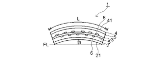
- the length in the longitudinal direction of the glass film laminate for a touch panel is L
- the maximum separation distance from the curved concave surface is h, 0.01 ⁇ h / L ⁇ 1 / ⁇ It is preferable that
- the touch panel according to the present invention created to solve the above problem is characterized in that a display device is provided on the curved convex surface side of the glass film laminate for a touch panel having the above-described configuration.
- the method according to the present invention created to solve the above problems is a method for producing a glass film laminate for a touch panel comprising a glass film and a transparent adhesive layer, and having a laminated structure of at least three layers, Laminating the glass film and the non-adhesive transparent adhesive layer on a plane to produce a temporary laminate, and holding the temporary laminate in a bending jig, the temporary laminate is in a curved state,
- the glass film and the transparent adhesive layer are fixed by performing a process of exerting the adhesive force of the transparent adhesive layer under the curved state, and then the bending jig is removed.
- the treatment for exerting the adhesive force of the transparent adhesive layer is a heat treatment below the strain point of the glass film.
- the present invention by using a glass film having a thickness of 200 ⁇ m or less, it is possible to reduce the weight of the glass film laminate for a touch panel.
- One outer surface of both outermost layers exhibits a curved concave surface, and the other outer surface exhibits a curved convex surface, whereby a curved glass film laminate for a touch panel can be obtained.
- the compressive stress layer is formed on the curved concave surface, durability of the curved concave surface is improved.
- a highly durable glass film laminate for a touch panel can be obtained.
- the glass film laminate for a touch panel is curved, the assembling work is facilitated as compared with the case where a flat glass film laminate is curved by an external force and incorporated into the apparatus.
- a conductive glass film in which a transparent conductive layer is formed on both sides it is preferable to use a conductive glass film in which a transparent conductive layer is formed on both sides, and if so, a touch panel capable of making wiring arrangement compact can be produced.
- a compressive stress layer is formed on the transparent adhesive layer. If so, the compressive stress layer is favorably formed on the curved concave surface side of the glass film laminate for a touch panel. can do. In addition, the durability of the glass film laminate for a touch panel can be improved.
- the degree of curvature is preferably 0.01 ⁇ h / L ⁇ 1 / ⁇ . If so, the touch panel is easy to be operated by the operator when the touch panel is manufactured. It can be set as the glass film laminated body for use.
- a display device is provided on the curved convex surface side. If so, a touch panel glass film laminate is mounted on the display device to produce a touch panel. Moreover, since an operator does not touch the curved convex surface side in which the tensile stress layer is formed, it can prevent that the glass film laminated body for touch panels is damaged from the curved convex surface side. Since the curved concave surface side becomes the operation surface, the moving distance for moving the finger or the like during the operation can be reduced, and the need for moving the fulcrum of the operation is reduced.
- a glass film laminate for a touch panel can be produced by fixing the glass film and the transparent adhesive layer by performing a treatment for exerting the adhesive force of the transparent adhesive layer under a curved state.
- the glass film laminated body for touchscreens can be produced by a simple work process, without requiring the heat bending process of glass.
- the temperature at the time of lamination is preferably equal to or lower than the strain point of the glass film, and if so, even if the glass film and the transparent adhesive layer are fixed on the bending jig, Since the bending compressive stress given to the glass film is not relaxed, a compressive stress layer can be formed on the curved concave surface side even when a glass film laminate for a touch panel is produced. And since the temperature of a heating is below the strain point of a glass film, compared with the heat bending process of heating to the softening point or more of a glass film, a required calorie
- FIG. 1 FIG. 3, FIG. 4, FIG. 5 and FIG. 6, hatching is omitted for convenience.
- a glass film laminate (1) for a touch panel according to the present invention includes a first glass film (2), a second glass film (3), and a third glass film (4) as shown in FIG. It has two transparent adhesive layers (5), both outermost layers are formed of the first and third glass films (2) and (4), and both surfaces of the second glass film (3) A transparent conductive layer (6) is formed.
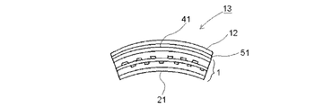
- the glass film laminate (1) for the touch panel itself exhibits a curved state without applying external force, and the curved concave surface (21) and the curved convex surface (41) are formed. The curved concave surface (21) is compressed. A stress layer is formed on the curved convex surface (41).
- the glass film laminated body (1) for touchscreens which concerns on this embodiment is curving only with respect to the left-right direction of the figure, and is not curving with respect to the direction orthogonal to a paper surface.
- silicate glass is used, respectively, preferably silica glass, borosilicate glass, soda lime glass, aluminosilicate. Salt glass is used, and most preferably non-alkali glass is used.
- non-alkali glass By using non-alkali glass as these glass films (2), (3), (4), the transparency of the glass film laminate (1) for touch panels can be improved, and when used as a touch panel It is possible to prevent the color of the internal display device from being damaged. Glass generally has excellent weather resistance, but when these glass films (2), (3), and (4) contain an alkali component, cations are dropped on the surface, so-called soda.
- the alkali-free glass is a glass that does not substantially contain an alkali component (alkali metal oxide), and specifically, a glass having a weight ratio of the alkali component of 1000 ppm or less. It is.
- the weight ratio of the alkali component in the present invention is preferably 500 ppm or less, more preferably 300 ppm or less.
- each of the first, second and third glass films (2), (3) and (4) is 200 ⁇ m or less, preferably 5 ⁇ m to 200 ⁇ m, most preferably 50 ⁇ m to 100 ⁇ m.
- the thickness of these glass films (2), (3), and (4) can be further reduced to reduce the weight of the glass film laminate (1) for the touch panel and to provide flexibility.
- these glass films (2), (3), and (4) can be laminated
- the flexibility of the glass film laminate (1) for the touch panel is too high, and it may be difficult to maintain the curved state of the glass film laminate (1) for the touch panel.
- the thickness of these glass films (2), (3), (4) exceeds 200 ⁇ m, the rigidity of these glass films (2), (3), (4) becomes transparent adhesive layer (5).
- the glass film laminate for touch panel (1) may return to a flat plate state, and the glass film laminate for touch panel (1) may not easily exhibit a curved state.
- the first, second, and third glass films (2), (3), and (4) used in the present invention each use a known float method, rollout method, slot down draw method, redraw method, etc. Although it can manufacture, it is preferable to shape
- the glass films (2), (3), and (4) produced by the overflow downdraw method do not need to be adjusted in thickness by polishing, grinding, chemical etching, or the like.
- the overflow down draw method is a molding method in which both sides of the glass plate do not come into contact with the molded member at the time of molding, and both sides (translucent surface) of the obtained glass plate are fire-making surfaces and do not polish. Even high surface quality can be obtained. Thereby, adhesive force with a transparent contact bonding layer (5) can be improved.
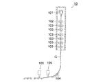
- FIG. 2 is a view showing a glass film manufacturing method (molding method) by an overflow downdraw method.
- a molded body (101) having a wedge-shaped cross section is disposed, and glass (molten glass) melted in a melting furnace (not shown) is supplied to the molded body (101).
- the molten glass overflows from the top of the molded body (101).
- the molten glass which overflowed passes along the both sides
- the glass film ribbon (G) immediately after joining at the lower end of the molded body (101) is stretched downward while the shrinkage in the width direction is restricted by the cooling roller (102), and becomes thin to a predetermined thickness.
- the glass film ribbon (G) having reached the predetermined thickness is gradually cooled by a slow cooling furnace (annealer) by feeding it with a roller (103), and the glass film ribbon (G) is gradually cooled except for thermal strain.
- the glass film ribbon (G) is sufficiently cooled to a temperature of about room temperature.
- the glass film ribbon (G) that has passed through the slow cooling furnace has its traveling direction changed from the vertical direction to the horizontal direction by the bending auxiliary roller (104), and then the unnecessary portions present at both ends in the width direction of the glass film ribbon (G) ( A portion where the cooling roller (102), the roller (103) and the like are in contact) is cut along the longitudinal direction by the first cutting device (105). Then, this glass film ribbon (G) is cut
- a glass film ribbon (G) After cutting a glass film ribbon (G) along the width direction for every predetermined length with a 2nd cutting device (106), those unnecessary parts are cut and removed with a 1st cutting device (105).
- the glass films (2), (3) and (4) may be produced by Moreover, in the above-mentioned shaping
- a glass roll is prepared by winding the glass film ribbon (G) into a roll shape through a slip sheet without cutting in the width direction later, and a film forming process described later is performed by a so-called roll-to-roll method. May be.
- the transparent conductive layer (6) is a layer provided for imparting conductivity to the second glass film (3) which is a dielectric. Therefore, the 2nd glass film (3) which has a transparent conductive layer (6) on both front and back turns into a conductive glass film.
- the transparent conductive layer (6) metal thin films such as gold, silver, and aluminum, oxide thin films such as tin-containing indium oxide (ITO), antimony-containing tin oxide, fluorine-containing tin oxide, and aluminum-containing zinc oxide can be used.
- ITO tin-containing indium oxide
- antimony-containing tin oxide antimony-containing tin oxide
- fluorine-containing tin oxide fluorine-containing tin oxide
- aluminum-containing zinc oxide can be used.
- ITO is preferable because film formation is relatively easy and visible light transmittance can be increased.
- the transparent conductive layer (6) can be formed by using an ion plating method, a sputtering method, a vacuum deposition method, or the like.
- a dense film can be formed and the wear resistance is excellent. Therefore, it is preferable.
- the glass film (3) is used as a base material which forms a transparent conductive layer (6) into a film, it is excellent in heat resistance compared with the case where a transparent resin board is used as a base material. . Therefore, in the case where the transparent conductive layer (6) is formed on the second glass film (3), a film forming step can be performed in a high temperature environment of 150 ° C. or higher, and a film having a low volume resistivity can be formed. Can be formed. Thereby, compared with the case where it forms into a film at normal temperature, it becomes possible to make the film thickness of a transparent conductive layer (6) about 50% thinner.
- the glass film laminate (1) for a touch panel according to the present invention forms a resist layer (not shown) after forming the transparent conductive layer (6) for use in a touch panel.
- an etching process for patterning the transparent conductive layer (6) is performed on the patterned resist layer using an etching solution such as hydrochloric acid.
- the peeling process which peels a resist layer from the transparent conductive layer (6) is performed using peeling liquid, such as KOH.
- peeling liquid such as KOH.
- the glass film laminate (1) for a touch panel is produced by fixing the transparent adhesive layer (5) in a curved state as described later.
- the material of the transparent adhesive layer (5) is not particularly limited, and a double-sided pressure-sensitive adhesive sheet, a thermoplastic adhesive sheet, a thermally crosslinkable adhesive sheet, an energy curable liquid adhesive, and the like can be used. You may adhere
- the thickness of the transparent adhesive layer (5) is preferably 5 to 500 ⁇ m.
- the glass film laminate (1) for a touch panel according to the present invention has a curved shape itself without being given external force such as bending stress. Thereby, one outer surface (the outer surface of the first glass film (2)) of the outermost layer exhibits a curved concave surface (21), and the other outer surface (the outer surface of the third glass film (4)) is The curved convex surface (41) is exhibited. A compressive stress layer is formed on the curved concave surface (21), and a tensile stress layer is formed on the curved convex surface (41).
- the compressive stress value of the compressive stress layer formed on the curved concave surface (21) is preferably 1 MPa to 100 MPa.
- the tensile stress value of the tensile stress layer formed on the curved convex surface (41) is preferably low, and is preferably a stress value that does not damage the glass film laminate for a touch panel.
- the glass film laminate (1) for a touch panel according to the present invention preferably has a compressive stress layer formed on the transparent adhesive layer (5).
- the compressive stress existing in the transparent adhesive layer (5) can support the curved force of the glass film (2) trying to return to the original flat plate state, and the compressive stress is favorably applied to the curved concave surface (21).
- a layer can be formed, and the durability of the transparent adhesive layer (5) can be improved.
- a method of forming a compressive stress layer on the curved concave surface (21) it is conceivable to produce a glass film laminate for a touch panel in a flat plate state and bend it at the time of touch panel production.
- the glass film laminate is mounted on the touch panel, and handling at the time of mounting may be difficult, and durability of the touch panel may be reduced.
- a tensile stress layer is formed on the transparent adhesive layer (5), and an elastic body such as a resin is always pulled. If maintained in a state where stress is applied, there is a risk of partial breakage due to deterioration over time, and sealability may be reduced due to partial breakage.
- the glass film laminate (1) for a touch panel has a length in the longitudinal direction of the glass film laminate (1) for a touch panel and a flat (FL) glass film laminate for a touch panel.
- the maximum separation distance between the flat surface (FL) and the curved concave surface (21) when the curved concave surface (21) is placed on the lower surface is h, 0.01 ⁇ h / L ⁇ 1 / ⁇ It is preferable that Thereby, when a touch panel is produced, it can be set as a touch panel with high durability and good operativity.
- h / L is smaller than 0.01, the compressive stress value of the compressive stress layer formed on the curved concave surface (21) tends to be small.
- h / L exceeds 1 / ⁇ the touch panel is manufactured.
- the operability may be deteriorated.
- FIG. 3 and FIG. 4 are views showing a first manufacturing method of the glass film laminate (1) for a touch panel according to the present invention.
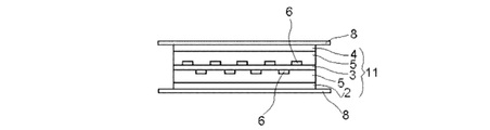
- the glass film laminate (1) for a touch panel according to the present invention is in a planar state, in a first glass film (2), a non-adhesive transparent adhesive layer (5), and a transparent conductive layer (6 ) Are laminated on the second glass film (3), the non-adhesive transparent adhesive layer (5), and the third glass film (4) in this order to produce a temporary laminate (11).
- the front and back surfaces of the temporary laminate (11) are sandwiched between release sheets (8).
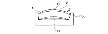
- the temporary laminate (11) is wrapped in the vacuum bag (9) together with the release sheet (8), and a short side support bending jig (71) (curving treatment) supporting the opposing short sides.
- a temporary laminated body (11) By supporting with a tool (7)), a temporary laminated body (11) is curved. Thereby, a compressive stress layer is formed on the curved concave surface (21), and a tensile stress layer is formed on the curved convex surface (41).
- the release sheet (8) is omitted.
- the inside of the vacuum bag (9) is depressurized and held at a predetermined pressure for a certain period of time, thereby preliminarily pressing the temporary laminate (11).
- the transparent adhesive layer (5) is softened by heating for a certain period of time at a temperature below the strain point of the glass films (2), (3), and (4) in an electric furnace (not shown) to soften the transparent adhesive layer (5).
- the adhesive force of (5) is exhibited, and the first glass film (2), the transparent adhesive layer (5), the second glass film (3), the transparent adhesive layer (5), and the third glass film (4). Is fixed. Thereafter, the glass film laminate (1) for a touch panel is obtained by lowering the temperature to room temperature, removing it from the bending jig (7), taking it out from the vacuum bag (9), and removing the release sheet (8).
- the transparent adhesive layer (5) is preferably non-tacky at room temperature. This is because the temporary laminate (11) is easily bent when being bent by the bending jig (7).
- the release sheet (8) is preferably slightly larger than the temporary laminate (11). In other words, it is preferable that the entire peripheral edge of the release sheet (8) protrudes from the temporary laminate (11). In this case, by heating the temporary laminate (11) to a temperature equal to or lower than the strain point, the softened transparent adhesive layer (5) may protrude from the temporary laminate (11), and the bending jig (7 ) And the vacuum bag (9).
- a resin sheet such as silicone or fluororesin.
- the heating temperature of the temporary laminated body (11) in the process of exerting the adhesive force of the transparent adhesive layer (5) is not higher than the strain point of the glass film.
- a compression stress layer was formed on the curved concave surface (21) with the bending jig (7) before the glass films (2), (3), (4) and the respective transparent adhesive layers (5) were fixed.
- the compressive stress is not relaxed at the time of fixing, the compressive stress layer can be maintained on the curved concave surface (21) even after fixing.
- the heating temperature in an electric furnace depends on the bonding temperature of the transparent adhesive layer (5) to be used and the heat resistance of the transparent adhesive layer (5), but is preferably 50 to 300 ° C, preferably 50 to More preferably, it is 200 degreeC.
- the heating time depends on the bonding time of the transparent adhesive layer (5) to be used, it can be 10 to 60 minutes as an example.
- an ultraviolet curable resin or the like is used as the transparent adhesive layer (5), it is possible to use an ultraviolet irradiation process instead of the heating process as a process for exerting the adhesive force of the transparent adhesive layer (5). In this case, it is also possible to perform a process for exerting the adhesive force of the transparent adhesive layer (5) at room temperature.
- tool (7) is both surfaces of a curved concave surface (21) and a curved convex surface (41). Therefore, the curved concave surface (21) and the curved convex surface (41) are excellent in surface quality.
- FIG. 5 is a view showing a second manufacturing method of the glass film laminate (1) for a touch panel according to the present invention.
- the second manufacturing method shown in FIG. 5 is different from the first manufacturing method shown in FIG. 4 described above in that the lower surface support bending jig (72) is used as the bending jig (7).
- the temporary support (11) and the release sheet (8) (not shown) are wrapped with the vacuum bag (9) together with the lower surface support bending jig (72).
- the curvature of the curved concave surface (21) can be freely designed by selecting the shape of the jig curved surface (73) of the lower surface supporting curved jig (72). can do.
- it is also possible to change the curvature of the glass film laminate (1) for the touch panel by making the both ends of the lower surface support bending jig (72) have a curved surface and making the central portion substantially flat. is there.
- the first glass film (2) and the transparent adhesive layer (5) are directly formed on the lower surface support bending jig (72) without producing the temporary laminate (11).
- a glass film for a touch panel is obtained by directly laminating and fixing a second glass film (3), a transparent adhesive layer (5), and a third glass film (4) each having a transparent conductive layer (6) formed on both surfaces in this order.
- a laminated body (1) can also be produced.
- a resin having adhesiveness at room temperature can be used as the transparent adhesive layer (5), and unlike the first production method, the adhesive of the transparent adhesive layer (5) in the heating step, the ultraviolet irradiation step, etc. It is also possible to omit the process of exerting power.
- the present invention uses the first manufacturing method and the second manufacturing method described above, and without performing thermal bending to raise the glass film (2), (3), (4) to the softening point,
- the glass film laminated body (1) for touchscreens which exhibits a curved state can be produced.
- the present invention can perform the laminating and fixing process at room temperature or a heat treatment below the strain point of the glass film, it is possible to use a glass film patterned with a precise transparent conductive film for a glass film laminate for a touch panel. It becomes.
- the laminating operation is performed after the thermal bending and bending of the glass substrate, compressive stress due to bending is not applied to the curved concave surface.
- the laminating operation is performed at a normal temperature or a heat treatment step below the strain point, the curved concave surface (21) is given a compressive stress by bending, and corresponds to the touch surface of the operator.
- the curved concave surface side can be strengthened.
- FIG. 1 a five-layer structure of first glass film (2) / transparent adhesive layer (5) / second glass film (3) / transparent adhesive layer (5) / third glass film (4).
- the glass film laminate (1) for a touch panel has been described, but the transparent conductive layer (6) is formed on the transparent adhesive layer (5) side of the first glass film (2) and the third glass film (4).
- a three-layer structure in which the second glass film (3) is omitted can be used, and if the outermost layer is a glass film, a structure of six layers or more can be used.
- the manufacturing method of the glass film laminated body (1) for touchscreens which concerns on this invention, it is not limited to the above-mentioned 1st, 2nd manufacturing method, Adhesion with a glass film and a transparent contact bonding layer is in the curved state. If possible, any manufacturing method can be used.
- the glass film laminate (1) for a touch panel according to the present invention is bent in advance on the curved convex surface (41) side via a transparent adhesive layer (51), or is flexible.
- the touch panel (13) can be manufactured by incorporating it on a display device (12) such as a liquid crystal display device or an organic EL display device. Thereby, compressive stress is given to the curved concave surface (21) on the side operated by the operator and durability is improved, and the curved convex surface (41) side to which the tensile stress is imparted is transparent adhesive layer ( 51) and the display device (12).
- the present invention can be suitably used for a touch panel used in a mobile phone, a smartphone, a tablet type, or a notebook type PC.
Landscapes
- Engineering & Computer Science (AREA)
- Theoretical Computer Science (AREA)
- General Engineering & Computer Science (AREA)
- Physics & Mathematics (AREA)
- Human Computer Interaction (AREA)
- General Physics & Mathematics (AREA)
- Thermal Sciences (AREA)
- Position Input By Displaying (AREA)
- Laminated Bodies (AREA)
- Joining Of Glass To Other Materials (AREA)
Priority Applications (3)
| Application Number | Priority Date | Filing Date | Title |
|---|---|---|---|
| KR1020147028803A KR102071368B1 (ko) | 2012-10-05 | 2013-09-25 | 터치 패널용 유리 필름 적층체와 터치 패널, 및 터치 패널용 유리 필름 적층체의 제조 방법 |
| CN201380035081.2A CN104412206B (zh) | 2012-10-05 | 2013-09-25 | 触摸面板用玻璃薄膜层叠体、触摸面板以及触摸面板用玻璃薄膜层叠体的制造方法 |
| US14/429,103 US9927893B2 (en) | 2012-10-05 | 2013-09-25 | Glass film laminate for touch panel, touch panel, and method of manufacturing glass film laminate for touch panel |
Applications Claiming Priority (2)
| Application Number | Priority Date | Filing Date | Title |
|---|---|---|---|
| JP2012-222621 | 2012-10-05 | ||
| JP2012222621A JP5999340B2 (ja) | 2012-10-05 | 2012-10-05 | タッチパネル用ガラスフィルム積層体、及びタッチパネル、並びにタッチパネル用ガラスフィルム積層体の製造方法 |
Publications (1)
| Publication Number | Publication Date |
|---|---|
| WO2014054484A1 true WO2014054484A1 (ja) | 2014-04-10 |
Family
ID=50434812
Family Applications (1)
| Application Number | Title | Priority Date | Filing Date |
|---|---|---|---|
| PCT/JP2013/075887 Ceased WO2014054484A1 (ja) | 2012-10-05 | 2013-09-25 | タッチパネル用ガラスフィルム積層体、及びタッチパネル、並びにタッチパネル用ガラスフィルム積層体の製造方法 |
Country Status (6)
| Country | Link |
|---|---|
| US (1) | US9927893B2 (enExample) |
| JP (1) | JP5999340B2 (enExample) |
| KR (1) | KR102071368B1 (enExample) |
| CN (1) | CN104412206B (enExample) |
| TW (1) | TWI574183B (enExample) |
| WO (1) | WO2014054484A1 (enExample) |
Cited By (1)
| Publication number | Priority date | Publication date | Assignee | Title |
|---|---|---|---|---|
| WO2024158021A1 (ja) * | 2023-01-27 | 2024-08-02 | 日東電工株式会社 | スイッチ装置、電子装置 |
Families Citing this family (29)
| Publication number | Priority date | Publication date | Assignee | Title |
|---|---|---|---|---|
| JP2015099588A (ja) * | 2013-10-18 | 2015-05-28 | 日本電気硝子株式会社 | タッチパネル及び表示装置付タッチパネル |
| KR101951262B1 (ko) | 2014-03-31 | 2019-02-22 | 동우 화인켐 주식회사 | 박막 터치 스크린 패널의 제조 방법 |
| US9701099B2 (en) * | 2014-05-06 | 2017-07-11 | Darwin Hu | Single flexible cover for touch screen |
| JP2016042274A (ja) * | 2014-08-18 | 2016-03-31 | 凸版印刷株式会社 | タッチパネル及びその製造方法 |
| WO2016028660A1 (en) * | 2014-08-20 | 2016-02-25 | Corning Incorporated | Methods of forming shaped glass articles from glass sheets |
| TWI529449B (zh) * | 2014-08-26 | 2016-04-11 | 友達光電股份有限公司 | 顯示器與其製造方法 |
| KR102471237B1 (ko) * | 2015-01-21 | 2022-11-28 | 삼성디스플레이 주식회사 | 폴더블 표시장치 |
| JP2016207200A (ja) * | 2015-04-20 | 2016-12-08 | ホシデン株式会社 | タッチパネル及びその製造方法 |
| KR20160124665A (ko) * | 2015-04-20 | 2016-10-28 | 호시덴 가부시기가이샤 | 터치 패널 및 그 제조방법 |
| TWI564762B (zh) * | 2015-04-22 | 2017-01-01 | 恆顥科技股份有限公司 | 觸控薄膜疊層卷的製作方法與所製得之觸控薄膜疊層片 |
| JP2016224589A (ja) | 2015-05-28 | 2016-12-28 | アルプス電気株式会社 | 接続装置 |
| CN105093615B (zh) * | 2015-07-29 | 2018-01-26 | 合肥鑫晟光电科技有限公司 | 曲面显示面板及其制备方法、显示装置 |
| US20180072022A1 (en) * | 2016-09-14 | 2018-03-15 | Innolux Corporation | Curved stack structures, manufacturing methods thereof and curved electronic devices |
| TWI839775B (zh) | 2017-01-03 | 2024-04-21 | 美商康寧公司 | 具有彎曲的覆蓋玻璃以及顯示器或觸控面板的車輛內部系統及其形成方法 |
| JP6991137B2 (ja) * | 2017-01-17 | 2022-01-12 | 積水化学工業株式会社 | 充填接合材、保護シート付き充填接合材、積層体、光学デバイス及び光学デバイス用保護パネル |
| US10712892B2 (en) * | 2017-04-26 | 2020-07-14 | Sensel, Inc. | Pre-loading a resistive touch sensor device via lamination of differently curved surfaces |
| US11332011B2 (en) | 2017-07-18 | 2022-05-17 | Corning Incorporated | Cold forming of complexly curved glass articles |
| CN111033451B (zh) * | 2017-08-08 | 2023-06-16 | 阿尔卑斯阿尔派株式会社 | 输入装置的制造方法以及输入装置 |
| KR102574235B1 (ko) | 2017-09-12 | 2023-09-11 | 코닝 인코포레이티드 | 데드프론트 유리용 촉각 요소 및 이를 제조하는 방법 |
| US11065960B2 (en) | 2017-09-13 | 2021-07-20 | Corning Incorporated | Curved vehicle displays |
| DE102017122972B4 (de) * | 2017-10-04 | 2019-07-11 | Webasto SE | Verfahren zur Herstellung einer Fahrzeugscheibe |
| TWI844520B (zh) | 2017-10-10 | 2024-06-11 | 美商康寧公司 | 具有改善可靠性的彎曲的覆蓋玻璃的車輛內部系統及其形成方法 |
| CN107871453A (zh) * | 2017-10-31 | 2018-04-03 | 云谷(固安)科技有限公司 | 一种柔性显示模组及其制备方法 |
| CN109062450B (zh) * | 2018-09-30 | 2024-06-28 | 上海开亿信息科技有限公司 | 触控面板,智能教学黑板及一种制作智能教学黑板的方法 |
| US10884272B2 (en) * | 2018-10-17 | 2021-01-05 | Garmin Switzerland Gmbh | Energy-collecting touchscreen unit |
| CN113726985B (zh) * | 2020-05-21 | 2022-09-06 | 宁波舜宇光电信息有限公司 | 感光芯片组件、摄像模组及终端设备 |
| CN112125503A (zh) * | 2020-09-02 | 2020-12-25 | 四川旭虹光电科技有限公司 | 一种曲面玻璃热弯成型的方法 |
| CN116745246A (zh) * | 2021-03-23 | 2023-09-12 | 日本电气硝子株式会社 | 化学强化用的玻璃板、强化玻璃板的制造方法以及玻璃板 |
| JP7640081B2 (ja) * | 2021-04-21 | 2025-03-05 | 日東電工株式会社 | スイッチ装置 |
Citations (4)
| Publication number | Priority date | Publication date | Assignee | Title |
|---|---|---|---|---|
| JP2006018417A (ja) * | 2004-06-30 | 2006-01-19 | Matsushita Electric Ind Co Ltd | 平面パッドの製造方法 |
| JP2011184284A (ja) * | 2009-09-18 | 2011-09-22 | Nippon Electric Glass Co Ltd | ガラスフィルムの製造方法及びガラスフィルムの処理方法並びにガラスフィルム積層体 |
| WO2012037094A2 (en) * | 2010-09-14 | 2012-03-22 | Corning Incorporated | Appliance fascia and mounting therefore |
| JP2012133428A (ja) * | 2010-12-20 | 2012-07-12 | Mitsubishi Electric Corp | 表示装置 |
Family Cites Families (15)
| Publication number | Priority date | Publication date | Assignee | Title |
|---|---|---|---|---|
| JP2002202855A (ja) * | 2000-12-28 | 2002-07-19 | Matsushita Electric Ind Co Ltd | タッチパネル及びこれを用いた電子機器 |
| JP2008247732A (ja) | 2007-03-02 | 2008-10-16 | Nippon Electric Glass Co Ltd | 強化板ガラスとその製造方法 |
| KR20090015482A (ko) * | 2007-08-08 | 2009-02-12 | 써모세람코리아 주식회사 | 글라스-글라스 타입의 윈도우 일체형 박막 터치패널 및 그제조 방법 |
| TW200921483A (en) * | 2007-11-09 | 2009-05-16 | Tpk Touch Solutions Inc | Touch-control display panel with an electric-field shielding layer |
| US8123894B2 (en) | 2008-05-07 | 2012-02-28 | Apple Inc. | 3-dimensional curved substrate lamination |
| TWI379261B (en) | 2008-05-16 | 2012-12-11 | Au Optronics Corp | Curved display panel and manufacturing method thereof |
| JP5396167B2 (ja) * | 2009-06-18 | 2014-01-22 | 株式会社ワコム | 指示体検出装置及び指示体検出方法 |
| TWI461785B (zh) * | 2010-01-29 | 2014-11-21 | Mstar Semiconductor Inc | 觸控顯示面板與相關方法 |
| TWI381303B (zh) | 2010-02-09 | 2013-01-01 | Oji Paper Co | 導電性積層體及使用其之觸控面板 |
| US8766929B2 (en) | 2010-05-14 | 2014-07-01 | Atmel Corporation | Panel for position sensors |
| WO2011155403A1 (ja) * | 2010-06-10 | 2011-12-15 | 日本電気硝子株式会社 | 湾曲状ガラス樹脂積層体の製造方法 |
| SG179299A1 (en) * | 2010-09-13 | 2012-04-27 | Trimech Technology Pte Ltd | A display panel substrate assembly, an apparatus and a method for forming a display panel substrate assembly |
| JP5496851B2 (ja) * | 2010-10-22 | 2014-05-21 | 株式会社ジャパンディスプレイ | タッチパネル |
| US8808483B2 (en) * | 2010-11-05 | 2014-08-19 | Apple Inc. | Method of making a curved touch panel |
| US9329314B2 (en) * | 2012-07-13 | 2016-05-03 | Apple Inc. | Touch screen display with transparent electrical shielding layer |
-
2012
- 2012-10-05 JP JP2012222621A patent/JP5999340B2/ja not_active Expired - Fee Related
-
2013
- 2013-09-25 CN CN201380035081.2A patent/CN104412206B/zh not_active Expired - Fee Related
- 2013-09-25 KR KR1020147028803A patent/KR102071368B1/ko not_active Expired - Fee Related
- 2013-09-25 US US14/429,103 patent/US9927893B2/en not_active Expired - Fee Related
- 2013-09-25 WO PCT/JP2013/075887 patent/WO2014054484A1/ja not_active Ceased
- 2013-10-01 TW TW102135463A patent/TWI574183B/zh not_active IP Right Cessation
Patent Citations (4)
| Publication number | Priority date | Publication date | Assignee | Title |
|---|---|---|---|---|
| JP2006018417A (ja) * | 2004-06-30 | 2006-01-19 | Matsushita Electric Ind Co Ltd | 平面パッドの製造方法 |
| JP2011184284A (ja) * | 2009-09-18 | 2011-09-22 | Nippon Electric Glass Co Ltd | ガラスフィルムの製造方法及びガラスフィルムの処理方法並びにガラスフィルム積層体 |
| WO2012037094A2 (en) * | 2010-09-14 | 2012-03-22 | Corning Incorporated | Appliance fascia and mounting therefore |
| JP2012133428A (ja) * | 2010-12-20 | 2012-07-12 | Mitsubishi Electric Corp | 表示装置 |
Cited By (1)
| Publication number | Priority date | Publication date | Assignee | Title |
|---|---|---|---|---|
| WO2024158021A1 (ja) * | 2023-01-27 | 2024-08-02 | 日東電工株式会社 | スイッチ装置、電子装置 |
Also Published As
| Publication number | Publication date |
|---|---|
| US20150253914A1 (en) | 2015-09-10 |
| US9927893B2 (en) | 2018-03-27 |
| TW201419083A (zh) | 2014-05-16 |
| JP5999340B2 (ja) | 2016-09-28 |
| CN104412206A (zh) | 2015-03-11 |
| KR20150066490A (ko) | 2015-06-16 |
| KR102071368B1 (ko) | 2020-01-30 |
| TWI574183B (zh) | 2017-03-11 |
| JP2014075061A (ja) | 2014-04-24 |
| CN104412206B (zh) | 2017-06-30 |
Similar Documents
| Publication | Publication Date | Title |
|---|---|---|
| JP5999340B2 (ja) | タッチパネル用ガラスフィルム積層体、及びタッチパネル、並びにタッチパネル用ガラスフィルム積層体の製造方法 | |
| EP3560899B1 (en) | Method for manufacturing curved laminated glass and curved laminated glass | |
| JP2014073642A (ja) | 透明導電性ガラス基板、及びタッチパネル | |
| TWI489339B (zh) | 附裝飾之觸控感測器和其製造方法、以及使用於該附裝飾之觸控感測器之觸控感測器 | |
| US12133347B2 (en) | Flexible display module and mobile terminal | |
| US20180072022A1 (en) | Curved stack structures, manufacturing methods thereof and curved electronic devices | |
| TW201202026A (en) | Glass film laminated body | |
| CN104204920A (zh) | 光电前平面基板 | |
| CN107001136B (zh) | 层叠体及其制造方法 | |
| TWI619051B (zh) | Touch panel and touch panel with display device | |
| CN107813550A (zh) | 曲面层叠结构、其制造方法及曲面电子装置 | |
| JP2015101044A (ja) | 化学強化ガラス樹脂積層体及びその製造方法 | |
| JP5754739B2 (ja) | タッチセンサ | |
| JP6192293B2 (ja) | カバーガラス一体型タッチセンサとその製造方法、及びそれに用いる積層用シート | |
| KR20090086380A (ko) | 터치 패널용 실리콘 패드 | |
| JP2015063427A (ja) | ガラスフィルムの表面処理方法、ガラスフィルム積層体、およびガラスフィルム | |
| US20250013264A1 (en) | Flexible display module and mobile terminal | |
| CN101902217A (zh) | 数字电容式触控板结构改良 |
Legal Events
| Date | Code | Title | Description |
|---|---|---|---|
| 121 | Ep: the epo has been informed by wipo that ep was designated in this application |
Ref document number: 13844498 Country of ref document: EP Kind code of ref document: A1 |
|
| ENP | Entry into the national phase |
Ref document number: 20147028803 Country of ref document: KR Kind code of ref document: A |
|
| WWE | Wipo information: entry into national phase |
Ref document number: 14429103 Country of ref document: US |
|
| NENP | Non-entry into the national phase |
Ref country code: DE |
|
| 122 | Ep: pct application non-entry in european phase |
Ref document number: 13844498 Country of ref document: EP Kind code of ref document: A1 |