WO2014051033A1 - 多孔質媒体を利用したアッセイ装置 - Google Patents
多孔質媒体を利用したアッセイ装置 Download PDFInfo
- Publication number
- WO2014051033A1 WO2014051033A1 PCT/JP2013/076221 JP2013076221W WO2014051033A1 WO 2014051033 A1 WO2014051033 A1 WO 2014051033A1 JP 2013076221 W JP2013076221 W JP 2013076221W WO 2014051033 A1 WO2014051033 A1 WO 2014051033A1
- Authority
- WO
- WIPO (PCT)
- Prior art keywords
- microchannel
- space
- porous medium
- fluid
- liquid
- Prior art date
Links
Images


Classifications
-
- G—PHYSICS
- G01—MEASURING; TESTING
- G01N—INVESTIGATING OR ANALYSING MATERIALS BY DETERMINING THEIR CHEMICAL OR PHYSICAL PROPERTIES
- G01N33/00—Investigating or analysing materials by specific methods not covered by groups G01N1/00 - G01N31/00
- G01N33/48—Biological material, e.g. blood, urine; Haemocytometers
- G01N33/50—Chemical analysis of biological material, e.g. blood, urine; Testing involving biospecific ligand binding methods; Immunological testing
- G01N33/53—Immunoassay; Biospecific binding assay; Materials therefor
- G01N33/558—Immunoassay; Biospecific binding assay; Materials therefor using diffusion or migration of antigen or antibody
-
- B—PERFORMING OPERATIONS; TRANSPORTING
- B01—PHYSICAL OR CHEMICAL PROCESSES OR APPARATUS IN GENERAL
- B01L—CHEMICAL OR PHYSICAL LABORATORY APPARATUS FOR GENERAL USE
- B01L3/00—Containers or dishes for laboratory use, e.g. laboratory glassware; Droppers
- B01L3/50—Containers for the purpose of retaining a material to be analysed, e.g. test tubes
- B01L3/502—Containers for the purpose of retaining a material to be analysed, e.g. test tubes with fluid transport, e.g. in multi-compartment structures
- B01L3/5027—Containers for the purpose of retaining a material to be analysed, e.g. test tubes with fluid transport, e.g. in multi-compartment structures by integrated microfluidic structures, i.e. dimensions of channels and chambers are such that surface tension forces are important, e.g. lab-on-a-chip
- B01L3/502769—Containers for the purpose of retaining a material to be analysed, e.g. test tubes with fluid transport, e.g. in multi-compartment structures by integrated microfluidic structures, i.e. dimensions of channels and chambers are such that surface tension forces are important, e.g. lab-on-a-chip characterised by multiphase flow arrangements
-
- B—PERFORMING OPERATIONS; TRANSPORTING
- B01—PHYSICAL OR CHEMICAL PROCESSES OR APPARATUS IN GENERAL
- B01L—CHEMICAL OR PHYSICAL LABORATORY APPARATUS FOR GENERAL USE
- B01L3/00—Containers or dishes for laboratory use, e.g. laboratory glassware; Droppers
- B01L3/50—Containers for the purpose of retaining a material to be analysed, e.g. test tubes
- B01L3/502—Containers for the purpose of retaining a material to be analysed, e.g. test tubes with fluid transport, e.g. in multi-compartment structures
- B01L3/5027—Containers for the purpose of retaining a material to be analysed, e.g. test tubes with fluid transport, e.g. in multi-compartment structures by integrated microfluidic structures, i.e. dimensions of channels and chambers are such that surface tension forces are important, e.g. lab-on-a-chip
- B01L3/50273—Containers for the purpose of retaining a material to be analysed, e.g. test tubes with fluid transport, e.g. in multi-compartment structures by integrated microfluidic structures, i.e. dimensions of channels and chambers are such that surface tension forces are important, e.g. lab-on-a-chip characterised by the means or forces applied to move the fluids
-
- C—CHEMISTRY; METALLURGY
- C12—BIOCHEMISTRY; BEER; SPIRITS; WINE; VINEGAR; MICROBIOLOGY; ENZYMOLOGY; MUTATION OR GENETIC ENGINEERING
- C12Q—MEASURING OR TESTING PROCESSES INVOLVING ENZYMES, NUCLEIC ACIDS OR MICROORGANISMS; COMPOSITIONS OR TEST PAPERS THEREFOR; PROCESSES OF PREPARING SUCH COMPOSITIONS; CONDITION-RESPONSIVE CONTROL IN MICROBIOLOGICAL OR ENZYMOLOGICAL PROCESSES
- C12Q1/00—Measuring or testing processes involving enzymes, nucleic acids or microorganisms; Compositions therefor; Processes of preparing such compositions
- C12Q1/54—Measuring or testing processes involving enzymes, nucleic acids or microorganisms; Compositions therefor; Processes of preparing such compositions involving glucose or galactose
-
- G—PHYSICS
- G01—MEASURING; TESTING
- G01N—INVESTIGATING OR ANALYSING MATERIALS BY DETERMINING THEIR CHEMICAL OR PHYSICAL PROPERTIES
- G01N33/00—Investigating or analysing materials by specific methods not covered by groups G01N1/00 - G01N31/00
- G01N33/48—Biological material, e.g. blood, urine; Haemocytometers
- G01N33/50—Chemical analysis of biological material, e.g. blood, urine; Testing involving biospecific ligand binding methods; Immunological testing
- G01N33/52—Use of compounds or compositions for colorimetric, spectrophotometric or fluorometric investigation, e.g. use of reagent paper and including single- and multilayer analytical elements
- G01N33/521—Single-layer analytical elements
-
- G—PHYSICS
- G01—MEASURING; TESTING
- G01N—INVESTIGATING OR ANALYSING MATERIALS BY DETERMINING THEIR CHEMICAL OR PHYSICAL PROPERTIES
- G01N33/00—Investigating or analysing materials by specific methods not covered by groups G01N1/00 - G01N31/00
- G01N33/48—Biological material, e.g. blood, urine; Haemocytometers
- G01N33/50—Chemical analysis of biological material, e.g. blood, urine; Testing involving biospecific ligand binding methods; Immunological testing
- G01N33/53—Immunoassay; Biospecific binding assay; Materials therefor
- G01N33/543—Immunoassay; Biospecific binding assay; Materials therefor with an insoluble carrier for immobilising immunochemicals
- G01N33/54366—Apparatus specially adapted for solid-phase testing
-
- B—PERFORMING OPERATIONS; TRANSPORTING
- B01—PHYSICAL OR CHEMICAL PROCESSES OR APPARATUS IN GENERAL
- B01L—CHEMICAL OR PHYSICAL LABORATORY APPARATUS FOR GENERAL USE
- B01L2200/00—Solutions for specific problems relating to chemical or physical laboratory apparatus
- B01L2200/16—Reagents, handling or storing thereof
-
- B—PERFORMING OPERATIONS; TRANSPORTING
- B01—PHYSICAL OR CHEMICAL PROCESSES OR APPARATUS IN GENERAL
- B01L—CHEMICAL OR PHYSICAL LABORATORY APPARATUS FOR GENERAL USE
- B01L2300/00—Additional constructional details
- B01L2300/06—Auxiliary integrated devices, integrated components
- B01L2300/069—Absorbents; Gels to retain a fluid
-
- B—PERFORMING OPERATIONS; TRANSPORTING
- B01—PHYSICAL OR CHEMICAL PROCESSES OR APPARATUS IN GENERAL
- B01L—CHEMICAL OR PHYSICAL LABORATORY APPARATUS FOR GENERAL USE
- B01L2300/00—Additional constructional details
- B01L2300/08—Geometry, shape and general structure
- B01L2300/0809—Geometry, shape and general structure rectangular shaped
-
- B—PERFORMING OPERATIONS; TRANSPORTING
- B01—PHYSICAL OR CHEMICAL PROCESSES OR APPARATUS IN GENERAL
- B01L—CHEMICAL OR PHYSICAL LABORATORY APPARATUS FOR GENERAL USE
- B01L2400/00—Moving or stopping fluids
- B01L2400/04—Moving fluids with specific forces or mechanical means
- B01L2400/0403—Moving fluids with specific forces or mechanical means specific forces
- B01L2400/0406—Moving fluids with specific forces or mechanical means specific forces capillary forces
Definitions
- the present invention relates to an assay device, and more particularly to a microfluidic device using a porous medium.
- a microfluidic device that performs biological and chemical screening using a small amount of liquid is generally manufactured using an expensive semiconductor manufacturing apparatus and requires complicated operations and external devices such as a pump. Durability and ease of use are obstacles to practical use. On the other hand, lateral flow and flow-through paper assay devices manufactured using a porous medium move the detection target in the porous medium due to capillary action, and interpret the presence or absence of the target. The above obstacles can be overcome without requiring complicated operations and external devices such as pumps. For this reason, it has attracted a great deal of attention in the environment where low cost is required, such as point-of-care testing (POCT) for medical diagnosis and developing countries.
- POCT point-of-care testing
- Patent Document 1 a method of sensitizing immunochromatography using a resonance plasmon effect between labeled substances such as antibodies (Patent Document 2), a polymerized photoresist or a curable polymer inside a hydrophilic porous medium
- Patent Document 3 a method of providing a formed fluid-impermeable barrier and realizing a complicated flow path pattern and reaction (Patent Document 3), and a method of developing a solution in a plurality of flow paths arranged in parallel to the dipstick method.
- Patent Document 1 a control line made of a casein solution or the like is used to prevent bleeding on a porous medium and to localize the band, thereby realizing high sensitivity. This improvement is limited to the case where bleeding has a large effect on the porous medium, and does not realize general-purpose and reliable high sensitivity and high accuracy.
- Patent Document 2 sensitization of color development and light emission is realized by a resonance plasmon effect between labeling substances, but the distance between the labeling substances is accurately controlled on a porous medium such as paper used for immunochromatography. This is difficult and sensitization with a certain reproducibility cannot be achieved for each assay.
- Patent Document 3 it is possible to integrate complicated fluid passages on a porous medium by patterning and laminating the porous medium, but complicated and expensive operations such as polymerization photoresist at the time of production. Need. Furthermore, the method for increasing the sensitivity is not specified.
- one object of the present invention is to provide an assay device that achieves high-sensitivity and high-accuracy in a general-purpose and reliable manner using a porous medium.
- Another object of the present invention is to provide an assay device that allows a multi-stage assay.
- the present inventors have intensively studied to solve the above-mentioned problems, and form a flow path space for a liquid sample in which no porous medium exists from two fluid-impermeable members and an interposed member disposed therebetween.
- the present invention has been completed by providing an assay region in such a space.
- the present invention is as follows.
- An assay device comprising: A microchannel having a tip, A porous medium disposed near the tip of the microchannel; A space portion disposed between the microchannel and the porous medium, The fluid that has moved in the microchannel based on the lateral flow is absorbed in contact with the porous medium beyond the space, and then separated in the space so that the fluid is retained in the microchannel.
- An assay device configured to be
- Item 2 The assay device according to Item 1, wherein a cross-sectional area of the space portion is larger than a cross-sectional area of the microchannel.
- Item 3 The assay device according to Item 1, wherein the volume of the space is 0.001 ⁇ l or more and 10,000 ⁇ l or less, and the volume ratio of the space to the microchannel is 0.01 or more.
- the fluid is a first liquid and a second liquid;
- the first liquid that has moved from the microchannel to the space is separated into two by the space, one is left in the microchannel, and one is absorbed by the porous medium,
- the second liquid that has moved through the microchannel pushes out the first liquid that has been placed in the microchannel to the porous medium, and the first liquid and the second liquid are exchanged.
- Assay device is a first liquid and a second liquid
- the width of the space portion is larger than the width of the microchannel, the height of the space is equal to or greater than the height of the microchannel, and the microchannel and the porous medium with respect to the width of the microchannel The ratio of the distance between and is 0.5-5 times,
- the microchannel and the space have the same width, the height of the space is larger than the height of the microchannel, and the distance B between the microchannel and the porous medium with respect to the width of the microchannel The ratio of 0.5 to 5, (Iii)
- the space is formed so as to be tapered from the tip of the microchannel to both sides in the width direction, and communicated with the space containing the porous medium at the end of the taper.
- the ratio of the distance between the microchannel and the porous medium to the width of the path 76 is 1 to 5, (Iv)
- the side surface of the microchannel is enlarged in a substantially arc shape on both sides in the width direction from the front end of the microchannel so as to taper on both sides in the width direction, and communicates with the space containing the porous medium at the end of the taper.
- the space portion is formed, and the ratio of the distance between the microchannel and the porous medium to the width of the microchannel is 1 to 5, or (v) the space portion of the microchannel is a plan view.
- a first portion that extends from the tip and curves toward the longitudinal axis passing through the center in the width direction of the microchannel, and passes through the inflection point and curves outward from the assay device in the opposite direction to the first portion.
- a second portion communicating with the space portion containing the porous medium, and having a side surface whose width increases from the tip of the microchannel toward the space portion containing the porous medium, and the microchannel
- the ratio of the distance between the micro-channel and the porous medium to the width of 1 to 5 is 1 to 5 Item 5.
- Item 6 The assay device according to Item 1, further comprising a second porous medium disposed in the fluid introduction part of the microchannel.
- Item 7. The assay device according to Item 6, further comprising plasma separation paper on the second porous medium.
- Item 8 The assay device according to Item 6, wherein the microchannel and the space are subjected to a hydrophilic treatment, and the first porous medium and the second porous medium are hydrophilic.
- Item 9 The assay device according to Item 1, wherein the microchannel, the space, the first porous medium, and the second porous medium are sandwiched between a pair of fluid-impermeable members.
- Item 10 The assay device according to Item 9, wherein the surface of the fluid impermeable member constituting the microchannel is a transparent sheet or film.
- Item 11 Item 2. The assay device according to Item 1, further comprising an assay reagent in a microchannel between the fluid introduction part and the space part.
- a multistage assay can be performed by repeatedly flowing and stopping a plurality of liquids continuously in the same channel.
- FIG. 1 Schematic sectional view of the microfluidic device of FIG. 1,
- FIG. 1 Schematic plan view.
- (A) to (f) Schematic showing the principle of solution exchange when two different solutions are applied.
- FIG. 6 is a schematic plan view of another embodiment of the microfluidic device of the present invention provided with an enlarged width portion.
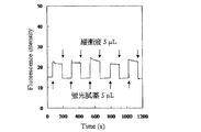
- the graph which shows the example of solution exchange.
- the horizontal axis represents time, and the vertical axis represents fluorescence intensity.
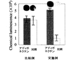
- the device on the left is a comparative device in which nitrocellulose paper is arranged in the assay region, and the device on the right is the device of the present invention.
- the dark bar is when there is 20 ng / ml (10 mL) adiponectin of the specimen, and the white bar refers to the control without specimen.
- the vertical axis represents the intensity of chemiluminescence.
- the graph which shows the assay result of the device of this invention which fixed the primary antibody and the secondary antibody to the microchannel beforehand.
- the graph which shows the assay result of another device of this invention using an enzyme The graph which shows the relationship between adiponectin concentration and chemiluminescence intensity.
- lateral flow refers to the flow of fluid that moves with gravity settling as the driving force.
- the movement of the fluid based on the lateral flow means that the driving force of the fluid due to gravity settling is dominant, which is different from the movement of the fluid due to the capillary phenomenon in which the interfacial tension is dominant (dominant).
- the “microfluidic device” refers to an apparatus that performs chemical or biochemical reaction in a channel capable of detecting or measuring an analyte with a fluid of the order of ⁇ l, that is, 1 ⁇ l or more and less than 1,000 ⁇ l. .
- microchannel refers to a channel space in a microfluidic device that enables detection or measurement of a specimen with a fluid of the order of ⁇ l, that is, 1 ⁇ l or more and less than 1,000 ⁇ l.
- liquid sample refers not only to a chemically pure liquid sample but also to a sample in which a gas, another liquid or solid is dissolved, dispersed or suspended in the liquid.
- analyte refers to a compound or composition that is detected or measured from a liquid sample, such as a saccharide (eg, glucose), protein or peptide (eg, serum protein, hormone, enzyme, immunomodulator, lymphokine).
- a saccharide eg, glucose
- protein or peptide eg, serum protein, hormone, enzyme, immunomodulator, lymphokine.
- fats amino acids, nucleic acids, steroids, vitamins, pathogens and their antigens, natural or synthetic chemicals, pollutants, for therapeutic purposes Or illegal drugs, as well as metabolites or antibodies of these substances.
- plastic refers to a material that can be polymerized or polymerized or molded using a polymer material as an essential component, and becomes a plastic material when heated to a temperature higher than the softening temperature.
- the plastic includes a polymer alloy in which two or more kinds of polymers are combined.
- film refers to a film-like material having a thickness of 200 ⁇ m or less
- sheet refers to a thicker film
- the term “soft” means that the fluid-impermeable member is hard enough to be deformed by the pressure of the liquid sample when the liquid sample is passed through.
- arranged at the end means that the end is arranged so that at least a part thereof is included, and “disposed near the end” means that the end is contacted. It may or may not be, but refers to being arranged next to the end without interposing another tangible member.
- FIG. 1 is an exploded perspective view of a microfluidic device 10 as an assay apparatus of the present invention.
- the microfluidic device 10 includes a first fluid impermeable member 12 and a second fluid impermeable member 20.
- first fluid impermeable member 12 and the second fluid impermeable member 20 are substantially rectangular transparent and soft sheets or films.
- the material of the first and second fluid-impermeable members 12 and 20 is, for example, plastic, and is preferably plastic having a contact angle of 90 degrees or less that promotes lateral flow (described later) of a hydrophilic liquid sample. .
- plastics include polyethylene (PE), polypropylene (PP), polyvinylidene chloride (PVDC), polystyrene (PS), polyethylene terephthalate (PET), polyvinyl chloride (PVC), polyolefin (PO), nylon, poly Biodegradability including methyl methacrylate (PMMA), cycloolefin copolymer (COC), cycloolefin polymer (COP), polycarbonate (PC), polydimethylsiloxane (PDMS), polyacrylonitrile (PAN), polylactic acid (PLA) Plastics or other polymers or combinations thereof can be mentioned.
- PE polyethylene
- PP polypropylene
- PVDC polyvinylidene chloride
- PS polystyrene
- PET polyethylene terephthalate
- PVC polyvinyl chloride
- PO polyolefin
- nylon nylon
- PMMA methyl methacrylate
- COC cycloolefin copolymer
- COP
- an adhesive tape 26 as an interposed member is disposed between the first fluid impermeable member 12 and the second fluid impermeable member 20, an adhesive tape 26 as an interposed member is disposed.
- the adhesive tape 26 has adhesive surfaces on the upper and lower surfaces, and the fluid-impermeable members 12 and 20 are respectively bonded to the adhesive tape 26 on the upper and lower surfaces of the adhesive tape 26 so as to be substantially parallel and substantially horizontal to each other.
- the first fluid impermeable member 12 has a proximal end portion 14 and a distal end portion 16
- the adhesive tape 26 has a proximal end portion 28 and a distal end portion 30, and the second fluid impermeable member 20 has a proximal end portion. It has a portion 22 and a tip portion 24.
- the three members 12, 20, and 26 are configured to have shapes and dimensions corresponding to the base end portions 14, 22, and 28 and the distal end portions 16, 24, and 30 stacked on each other.
- the proximal end portion 28 of the adhesive tape 26 is provided with an opening 32 into which a second porous medium, in particular, a developing paper 42 which is a hydrophilic porous medium is fitted, and the distal end portion 30 is made of the first porous medium.
- An opening 34 into which an absorbent paper 44 is fitted is provided, and the opening 32 and the opening 34 are connected to each other via a gap 40 formed between a pair of side extending portions 36 and 38.
- the gap 40 is narrower than the openings 32 and 34, and the pair of laterally extending portions 36 and 38 extend in the longitudinal direction of the gaps 40 and are separated from each other in the width direction perpendicular to the longitudinal direction. Are lined up.
- the developing paper 42 acts to permeate and spread the liquid sample.
- a projecting portion is provided on the front end side of the developing paper 42, the projecting portion is disposed in the gap 40, and a liquid sample that has been immersed in the developing paper 42 and developed is a micro channel 76 (FIG. 2 (FIG. 2)). a)).
- the absorbent paper 44 that absorbs the developed liquid sample is provided at a position separated from the microchannel 76 by a space portion 82 (see FIG. 2A), which will be described later, in the opening 34 into which the absorbent paper 44 is fitted. .
- the material of the spread paper 42 and the absorbent paper 44 may be the same or different.
- the developing paper 42 and the absorbent paper 44 are preferably a hydrophobic material when the liquid sample is hydrophobic, and are preferably a hydrophilic material when the liquid sample is hydrophilic.
- the developing paper 42 and the absorbent paper 44 are hydrophilic porous media, for example, cellulose, nitrocellulose, cellulose acetate, filter paper, tissue paper, toilet paper, paper towel, or cloth, or a hydrophilic porous polymer that transmits water It may be one of
- the developing paper 42 is preferably formed of a material that hardly or hardly adsorbs the test substance or assay reagent in the liquid sample. In addition, even if there is no development paper 42, it may be in a state where the liquid sample flows from the inlet to the microchannel 76 and is in a state where hydrophilic treatment / hydrophobic treatment is performed. Such a shape means that in the structure of the assay device from the injection port to the microchannel 76, the space to the microchannel 76 is not completely blocked so as to prevent the flow of the liquid sample. .
- the flow of the liquid sample to the micro flow path 76 is mainly caused by a lateral flow in the substantially horizontal direction in the micro flow path 76 of the liquid sample, and therefore, the primary side pressure before the liquid sample reaches the developing paper 42, and It is desirable that the differential pressure of the secondary side pressure after the liquid sample flows through the developing paper 42 is small, and the differential pressure is such that the differential pressure is less than the lateral flow of the liquid in the microchannel is stopped. Paper 42 needs to be selected.
- the amount of the liquid sample penetrating the developing paper 42 needs to be smaller than the total amount of liquid introduced from the inlet. In order to avoid the effect of slowing the flow rate, it is desirable that the developed paper 42 has a small amount of liquid that can penetrate.
- the amount of the liquid sample is usually in micro units, that is, about 1 ⁇ l or more and less than about 1 ml, preferably about 1.5 ⁇ l, more preferably about 3.0 ⁇ l or more, the detection sensitivity becomes stable and the detection becomes easy.
- the upper limit amount of the liquid sample is usually several ⁇ l to several hundred ⁇ l, for example. Thus, in many cases, even a single drop of liquid sample can be detected.
- the amount of the liquid sample may be less than or equal to the volume of the microchannel 76, but when the amount of the liquid sample is larger than the volume of the microchannel 76, the space portion 82 (FIG. )) works well as a valve mechanism.
- Liquid samples are in particular hydrophilic liquid samples, including human or animal whole blood, serum, plasma, urine, stool dilution, saliva, or cerebrospinal fluid. It is. In this case, a diagnostically effective sample in a liquid sample can be measured for uses such as pregnancy test, urine test, stool test, adult disease test, allergy test, infectious disease test, drug test, or cancer test.
- Liquid samples also include food suspensions, drinking water, river water, soil suspensions, etc., to measure pathogens in foods and drinking water, and in river water and soil. It is also possible to measure contaminants.
- the first fluid-impermeable member 12, the adhesive tape 26, and the second fluid-impermeable member 20 have the spread paper 42 disposed in the opening 32, the absorbent paper 44 disposed in the opening 34, and absorption.
- the paper 44 and the first fluid impermeable member 12 are connected to each other with an optional pair of double-sided adhesive tapes 46 and 48 provided.
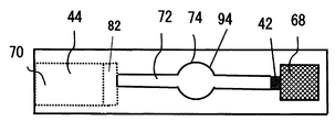
- the first fluid impermeable member 12, the second fluid impermeable member 20, and the adhesive tape 26 form a flow path 72 through which the liquid sample passes.
- the first fluid impermeable member 12, the second fluid impermeable member 20, and the pair of laterally extending portions 36, 38 define a linear micro flow path 76
- the development paper 42 is arranged at and near the base end portion 78 of the microchannel 76 as an introduction portion for a fluid or liquid sample.
- the tip 80 of the microchannel 76 is connected to the space 82, and the absorbent paper 44 is disposed at a position sandwiching the space 82 from the tip 80 of the microchannel 76.
- the configuration of the flow path 72 is such that the base end space for accommodating the developing paper 42, the micro flow path 76, the space portion 82 as a valve mechanism, and the absorbent paper 44 are accommodated continuously from right to left.
- the base end space that accommodates the developing paper 42 and the distal end space 84 that accommodates the absorbent paper 44 are substantially closed.
- the volume of the space portion 82 is larger than that of the micro flow channel 76, and the cross sectional area of the space portion 82 is larger than the cross sectional area of the micro flow channel 76.
- the volume of the space 82 is not particularly limited, but is usually 0.001 ⁇ l or more and 10,000 ⁇ l or less. Further, the volume ratio of the space 82 to the micro flow path 76 is not particularly limited, but is, for example, 0.01 or more.
- the space portion 82 and the microchannel 76 are preferably subjected to a hydrophilic treatment in order to increase the hydrophilicity of the surface in contact with the liquid sample.
- Hydrophilic treatment includes treatment with a blocking agent that prevents non-specific adsorption of specific conjugates in the liquid sample to the channel, including commercially available blocking agents such as Block®Ace, bovine serum albumin, Examples include casein, skim milk, gelatin, surfactant, polyvinyl alcohol, globulin, serum (eg, fetal bovine serum or normal rabbit serum), ethanol, and MPC polymer.
- blocking agents can be used alone or in admixture of two or more.
- the height of the microchannel 76 is, for example, about 15 ⁇ m or more and 1,000 ⁇ m (1 mm) or less.
- the width of the microchannel 76 is, for example, not less than about 100 ⁇ m and not more than about 10,000 ⁇ m (1 cm).
- the length of the microchannel 76 is, for example, not less than about 10 ⁇ m and not more than about 10 cm.
- the volume of the microchannel 76 is 0.1 ⁇ l or more and 1,000 ⁇ l or less, preferably 1 ⁇ l or more and less than 500 ⁇ l.
- an assay region 74 includes an assay reagent that reacts with a specimen in a liquid sample to produce a detectable result.
- This detectable result may be observable with the naked eye (for example, a color change) or may be detectable only with a spectrometer or other measuring means.
- the assay reagent may be a chemical or color reagent such as an iron (III) ion that develops color upon reaction with the sample, or reacts with an enzyme, antibody, epitope, or sample to produce a detectable result. It may be any other substance to be made.
- the assay reagent is fixed to the assay region 74 by a well-known immobilization technique such as physical adsorption method or chemical adsorption method, preferably the first fluid impermeable member 12 or the second fluid impermeable member 20, particularly preferably.
- the first fluid impermeable member 12 may be fixed.
- the assay reagent may be bound with an arbitrary labeling substance such as a radioisotope, an enzyme, a colored molecule such as gold colloid, latex, a dye, a fluorescent substance, or a luminescent substance in order to amplify a detection signal.
- an arbitrary labeling substance such as a radioisotope, an enzyme, a colored molecule such as gold colloid, latex, a dye, a fluorescent substance, or a luminescent substance in order to amplify a detection signal.
- the assay region 74 includes a first assay reagent fixing position 86 and a second assay reagent fixing position 88, and the analyte in the liquid sample reacts with the second assay reagent; After the complex of the specimen and the second assay reagent moves, the complex reacts with the first assay reagent, and usually the specimen-second assay reagent complex and the first assay at the fixed position 86 of the first assay reagent. The reagent forms an additional complex, and the signal of the complex is detected by known methods.
- the first assay reagent is a primary antibody
- the second assay reagent is a secondary antibody
- the primary and secondary antibodies bind to two different epitopes of the specimen
- the secondary antibody is The primary antibody binds to the epitope of the analyte and binds to the secondary antibody, at least one of the primary antibody and the secondary antibody is labeled, and the primary antibody is fixed at the fixing position 86, The secondary antibody moves from the fixed position 88 according to the flow of the liquid sample, and a complex of the antigen, the primary antibody, and the secondary antibody is detected at the fixed position 86.
- the assay reagent contains an antigen, and the signal of the complex produced by the antigen-antibody reaction is detected in the same manner.
- the sample is an enzyme, detection or measurement can be performed in the same manner using the specificity of the enzyme substrate reaction using the assay reagent as a substrate.
- the first assay reagent may be an enzyme and optionally the second assay reagent may be a color reagent.
- a control region is provided on the downstream side (tip side) where the assay reagent is provided in the microchannel 76 to confirm that a sufficient amount of sample has reached the assay region.
- the control region is provided with a control reagent that can bind to an analyte in the liquid sample and move with the flow of the liquid sample while moving with the flow of the liquid sample (for example, the second assay reagent described above), but does not bind to the analyte.
- the control reagent can be any molecule or composition known in the art.
- a cover member 50 serving as a first casing for providing robustness or rigidity to the microfluidic device 10 is provided on the first fluid-impermeable member 12. Also, below the second fluid-impermeable member 20, a base member 51 as a second casing for providing the strength or rigidity of the microfluidic device 10 is provided below the second fluid-impermeable member 20, a base member 51 as a second casing for providing the strength or rigidity of the microfluidic device 10 is provided below the second fluid-impermeable member 20, a base member 51 as a second casing for providing the strength or rigidity of the microfluidic device 10 is provided. The cover member 50 and the base member 51 are connected to the fluid-impermeable member 12 and the fluid-impermeable member 20 using the same adhesive tape as the adhesive tape 26 or a similar member.
- the cover member 50 includes a proximal end portion 54 and a distal end portion 56, and a pair of laterally extending portions 58, 60 extending in the longitudinal direction of the proximal end side of the distal end portion 56 and extending perpendicularly to the longitudinal direction. They are arranged side by side in the width direction. Therefore, a slit 62 as an opening for observing the assay region 74 is formed through most of the longitudinal direction of the cover member 50 between the pair of laterally extending portions 58 and 60. Since the slit 62 is in a position corresponding to the assay region 74, as shown in FIG. 2B, when the specimen in the liquid sample is analyzed by the microfluidic device 10 of the present invention, the slit 62 and the transparent second The observer can visually observe the assay region 74 through one fluid-impermeable member 12.
- the tip 52 of the base member 51 is provided with a recess 53 for accommodating the absorbent paper 44, and the micro flow path 76 can be kept horizontal even when the thickness (height) of the absorbent paper 44 is larger than the height of the adhesive sheet 26. Makes it possible to maintain.
- the adhesive tape 64 is disposed on the base end side of the base end portion 54 of the cover member 50, and a plasma separation paper 67 that separates plasma components from the whole blood is adhered on the adhesive tape 64.
- An adhesive tape 68 is further adhered on the plasma separation paper 67.
- Circular holes 66 and 69 are formed in the adhesive tapes 64 and 68. The circular holes 66 and 69 align with the circular holes 18 of the first fluid impermeable member 12 when the microfluidic device 10 is assembled.
- the adhesive tapes 64 and 68 are hydrophobic and function to prevent the liquid sample from leaking out from the circular hole 66, and the plasma separation paper 67 is sandwiched between the adhesive tapes 64 and 68, so that the plasma separation paper 67
- the degree of sealing is increased, drying of the liquid sample that wets the plasma separation paper 67 can be reduced, and the liquid sample in the flow path 72 is less likely to volatilize.
- the adhesive tape 68 is hydrophobic, the liquid sample placed on the hole 69 is prevented from leaking out of the hole 69 and can flow to the developing paper 42 with high reproducibility. .
- the cover member 50 and the base member 51 may be formed of any material, but are preferably formed of paper, particularly cardboard, in terms of cost reduction and manufacturability of the microfluidic device 10.
- the specimen is detected based on a color change, if the base member 51 is white, the color contrast due to the color change can be clearly read.
- the cover member 50 and the first fluid-impermeable member 12 are formed with air vent holes 70 penetrating the cover member 50 and the first fluid-impermeable member 12, and the liquid sample passes through the flow path 72 during the assay.
- the air from the flow path 72 is extracted from the microfluidic device 10.
- the first liquid 90 which is a liquid sample, is applied to the inlet of the microfluidic device 10 (FIG. 3A). Then, the first liquid 90 penetrates into the developing paper 42 by the capillary force, flows along the tip of the developing paper 42, and flows into the micro flow path 76 (FIG. 3B).
- the principle of fluid movement in the device of the present invention is considered as follows.
- peeling electrification occurs on the opposite surfaces of the fluid-impermeable members 12 and 20, thereby attracting water molecules to the surfaces of the fluid-impermeable members 12 and 20.
- the first liquid 90 flows without greatly reducing the moving speed.
- the flow of the liquid sample that has contacted the porous medium beyond the space (82) is absorbed by the porous medium by the space 82 that is the valve mechanism in front of the absorbent paper 44 installed in the downstream portion.
- the latter is separated into two parts, one in the absorbent paper 44 and the other in the microchannel 76 (FIG. 3C).
- the first liquid 90 flows stably until there is no excess permeate on the developing paper 42 (on the plasma separating paper 67 when the plasma separating paper 67 is present, and on the upper surface of the inlet when there is no developing paper 42).
- the first liquid 90 is entirely drawn into the microchannel 76.
- the second liquid 92 which is a reagent solution necessary for the assay is dropped (FIG. 3 (d))
- the second liquid 92 is moved again in the microchannel 76 by the lateral flow (FIG. 3 (e)).
- the entire amount is drawn into the micro flow path 76, and the first liquid 90 filled in advance is pushed out to the absorbent paper 44 and exchanged with the second liquid 92 (FIG. 3 (f)).
- the amount of the first liquid 90 is larger than the volume of the microchannel 76, and the first liquid 90 is filled in advance so as to fill almost the entire volume in the microchannel 76.
- the space 82 separates the flow of the first liquid 90 into two, and the first liquid 90 placed in the microchannel 76 is the microchannel.
- the first liquid 90 is placed in the micro flow path 76 so as to satisfy almost the entire volume in 76, and the first liquid 90 and the second liquid are exchanged. Therefore, a multi-step antigen-antibody reaction such as ELISA can be easily performed.
- the amount of the second liquid 92 is set to be equal to or larger than the amount of the first liquid 90 filled in the microchannel 76. If the amount of the second liquid 92 is smaller than the amount of the first liquid 90 filled in the micro flow path 76, the first liquid 90 does not flow through the micro flow path 76 even if the second liquid 92 is flowed through the micro flow path. The first liquid 90 and the second liquid 92 remaining as a sphere at the tip 80 are not well separated. Alternatively, even if the sphere composed of the first liquid 90 is broken at the tip 80 and absorbed by the absorbent paper 44, the entire amount of the first liquid 90 filled in the microchannel 76 cannot be reliably exchanged. .
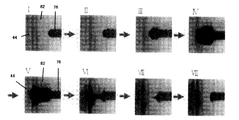
- FIGS. 4I to VIII show an experiment using a blue ink solution for confirming the action of the valve mechanism of the microfluidic device 10.
- Absorbent paper 44 was placed on the tip side of the microchannel, and a blue ink solution was injected into the microchannel.
- the width of the space 82 is larger than the width of the microchannel 76, preferably 2 times or more, more preferably 3 times or more.
- the ratio of the distance between the microchannel 76 and the absorbent paper 44 with respect to the width of the microchannel 76 is about 0.5 to about 5 times, more preferably about 1 to 5 times.
- the height of the bottom surface of the space portion 82 is the same as the height of the bottom surface of the microchannel 76.
- the liquid in the micro flow channel is in contact with the developing paper 42 arranged on the upstream side, the liquid in the flow channel is not sucked into the absorbent paper 44 on the downstream side (FIG. 4VIII).
- a valve mechanism that autonomously repeats the growth and destruction of the sphere on the downstream side of the microchannel, it is possible to automatically flow and leave the liquid in the microchannel.
- the interfacial tension acting between the wall surface of the microchannel and the liquid acts predominantly, and the fluid moves so as to pull up the liquid depending on the surface tension of the liquid.
- the tip of the fluid In the process of flowing, the tip of the fluid is concavely curved with respect to the space, and the surface tension of the liquid acts to reduce the surface area, so that a force acts to flatten the concave surface. Since the front end of the fluid needs to be horizontal in order to become flat, the liquid flows as a result.
- the tip of the microchannel does not form a sphere with the liquid shape convex to the space. Therefore, when the capillary force is dominantly acting on the fluid rather than the lateral flow, the phenomenon that the fluid leaks from the tip portion does not occur.
- the first liquid blue ink is allowed to flow through the microchannel 76.
- the fluid stays in the space portion 82 in a state of being continuous with the ink in the microchannel 76 without repeating the growth and destruction of the sphere (FIGS. 5I-V), and eventually the space portion.
- the absorbent paper 44 is reached (FIG. 5 VI-VIII).
- the second liquid 92 also continues in the space 82 in a state of being continuous with the ink in the microchannel 76 without repeating the growth and destruction of the sphere. And mixed with the first liquid 90 remaining in the space 82 (FIG. 5IX-XII).
- the ink flowing through the micro flow channel 76 and the ink in the space 82 are not separated, resulting in poor solution exchange.
- the effect of the first embodiment will be described.
- the detection sensitivity is greatly increased compared to the conventional immunochromatography or dipstick method in which the assay region is present in the porous medium.
- the improvement of the frequent false positive and false negative problems can be greatly expected.
- the microchannel 76 is a space, a small amount of the liquid sample is generally required as compared with the conventional immunochromatography or dipstick method in which the liquid sample moves on the porous medium.
- the measurement sensitivity is high and stable, the sample can be quantified.
- first and second fluid-impermeable members 12 and 20 that define the micro flow path 76 are made of a plastic soft film or sheet having a contact angle of 90 degrees or less, an external device such as a pump
- the liquid sample can be moved by an autonomous lateral flow without using the.
- the first fluid-impermeable member 12 and the second fluid-impermeable member 20 are transparent sheets or films, the assay region 74 in the microchannel 76 can be visually observed.
- the capillary force of the absorbent paper 44, the surface tension of the gas-liquid interface of the liquid sample, and the space 82 as a valve mechanism are installed.
- the fluid that has moved in the micro flow channel 76 mainly based on the lateral flow grows into a sphere in the space portion 82 at the distal end portion 80, and the sphere in contact with the absorbent paper 44 is destroyed and porous.
- the shape and / or dimensions are absorbable by the quality medium 44.
- the operation of “flowing / stopping” the liquid sample into the microchannel can be autonomously performed.
- the microchannel 76 can be configured at a lower cost and more easily than thermocompression bonding.
- the developing paper 42 which is a hydrophilic porous medium, is provided at the base end portion of the flow path 72, the liquid that has passed through the plasma separation paper 67 is reliably reproduced from the developing paper 42 into the micro flow path 76. Is sucked in and fluidized.
- plasma separation using a separation membrane or a fine channel often causes problems such as blood flow aggregation or clogging, or the separation flow stops, or hemolysis or blood cell components are mixed by strong pressure from a pump or the like.
- the spread paper and / or the porous medium is cellulose, nitrocellulose, cellulose acetate, filter paper, tissue paper, toilet paper, paper towel, fabric, porous polymer, etc. Can be used easily.
- the microfluidic device 10 can be manufactured very inexpensively and easily using commercially available inexpensive porous media, transparent film, adhesive tape, and paper, it can be purchased so far in hospitals in developing countries. In addition to being able to expand to new customers, it can also be expanded to OTC markets in Japan and developed countries, contributing to improving the quality of life (QOL) of people around the world.
- the material of the component of the microfluidic device 10 is, in particular, the material of the first and second fluid-impermeable members 12 and 20 is plastic, the interposed member is the adhesive tape 26, the cover member 50 and the base member 51 are paper. Since all of the materials are soft as described above, the sample in the microchannel 76 can be collected by cutting with a scissors or a cutter. Therefore, it can be used as a life science research support tool for the next phase such as gene analysis.
- At least one of the first and second fluid-impermeable members 12, 20 and the interposition member may be translucent or opaque, and in addition to plastic, fluid such as resin, glass or metal It may be formed from other materials that do not penetrate.
- the materials of the first and second fluid-impermeable members 12, 20 and the interposition member may be the same or different. When the materials of the first and second fluid-impermeable members 12, 20 and the interposition member are different, only the first fluid-impermeable member 12 may be a transparent material, or the first fluid-impermeable member 12 Only the permeable member 12 may be a soft sheet or film.
- the shape and dimensions of the hole 18 of the first fluid-impermeable member 12 and the hole 66 of the adhesive tape 64 are not particularly limited as long as they communicate with the developing paper 42.
- the height of the bottom surface of the space portion 82 is lower than the height of the bottom surface of the microchannel 76.
- the height of the bottom surface of the space portion 82 and the bottom surface of the microchannel 76 May be the same.
- the shape of the space portion 82 is not limited to the shape of the first embodiment. For example, various shapes shown in the plan views of FIGS. 7A to 7D and the side views of FIGS.
- the adhesive tape 96 is provided on the bottom surfaces of the micro flow path 76 and the space 82, and the same material as that of the second fluid impermeable member 20 is provided thereon.
- a fluid-impermeable sheet 98 which may be a different material or a different material, is provided, and a hydrophilic treatment layer with a blocking agent is provided on the sheet 98. A portion where the sheet 98 ends and the adhesive tape 96 is exposed forms a space 82.
- the width of the microchannel 76 and the space portion 82 is the same, and the upper surface of the space portion 82 is the first fluid-impermeable member 12 that is the same as the upper surface of the microchannel 76, and the bottom surface of the space portion 82 is the microflow channel. It is lower than the bottom surface of the road 76. That is, the height of the space portion 82 is larger than the height of the microchannel 76.
- the ratio (B / A) of the distance B between the microchannel 76 and the absorbent paper 44 as the first porous medium to the width A of the microchannel 76 is preferably 0.5 to 5.
- FIGS. 7B and 7F it expands in a tapered shape from the front end of the microchannel 76 in the width direction in a plan view, and communicates with the space that accommodates the absorbent paper 44 at the end of the taper.
- a space 82 is formed. That is, the space portion 82 corresponds to a trapezoidal portion in plan view.
- a fluid-impermeable sheet 98 which may be the same material as the second fluid-impermeable member 20 or a different material, is provided on the bottom surfaces of the microchannel 76 and the space 82.
- a hydrophilic treatment layer with a blocking agent is applied thereon.
- the ratio (B / A) of the distance B between the microchannel 76 and the absorbent paper 44 to the width A of the microchannel 76 is preferably 1 to 5.
- FIGS. 7 (c) and 7 (g) in a plan view, from the front end of the microchannel 76, it is substantially arcuate on both sides in the width direction (generally a quarter of a circle) and is tapered on both sides in the width direction.
- the side surface is enlarged, and a space portion 82 is formed so as to communicate with the space for accommodating the absorbent paper 44 at the end of the taper.
- a fluid-impermeable sheet 98 which may be the same material as the second fluid-impermeable member 20 or a different material, is provided on the bottom surfaces of the microchannel 76 and the space 82.
- a hydrophilic treatment layer with a blocking agent is applied thereon.
- the ratio (B / A) of the distance B between the microchannel 76 and the absorbent paper 44 to the width A of the microchannel 76 is preferably 1 to 5.
- the space 82 is curved toward the longitudinal axis extending from the tip of the microchannel 76 and passing through the center in the width direction of the microchannel in plan view.
- a fluid-impermeable sheet 98 which may be the same material as the second fluid-impermeable member 20 or a different material, is provided on the bottom surfaces of the microchannel 76 and the space 82. Further, a hydrophilic treatment layer with a blocking agent is applied thereon.
- the ratio (B / A) of the distance B between the microchannel 76 and the absorbent paper 44 to the width A of the microchannel 76 is preferably 1 to 5.
- the upper surface of the space portion 82 is the upper surface of the microchannel 76. It is composed of the same first fluid impervious member 12 and is flush.
- the bottom surface of the space portion 82 is preferably lower than the bottom surface of the microchannel 76, and the height of the space portion 82 is preferably greater than the height of the microchannel 76, but the bottom surface of the space portion 82 and the bottom surface of the microchannel 76 are also flush. It may be.
- the space portion 82 acts as a valve mechanism, so that solution exchange is performed well (data not shown).
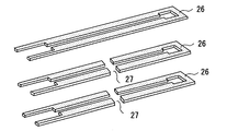
- the interposition members including the adhesive tape 26 may be stacked with a plurality of interposition members.
- the interposition member is not limited to a single member, and may be composed of a plurality of members connected in the horizontal direction so that there is no leakage of the liquid sample.
- three adhesive tapes 26 may be laminated and bonded.
- the two lower adhesive tapes 26 are cut in the middle of the longitudinal direction, and when the three are laminated, the thickness of the microchannel 76 can be reduced at the location of the cut 27, but the second fluid If the impermeable member 20 is made of a soft film such as PVDC, it is possible to cover the flow paths with different steps according to the unevenness. Providing a location where the thickness is increased in the flow path creates a protrusion for the liquid sample to remain in the flow path due to the viscous force.As a result, the force for the fluid to remain in the flow path is increased. It can be reduced.
- the interposition member is not limited to the adhesive tape 26, and any other member may be used as long as it can seal the space where the fluid including the microchannel 76 and the space 82 flows.
- it may be joined to the fluid-impermeable members 12 and 20 by thermocompression bonding using plastic or film as an interposed member, or may be joined using an adhesive, or surface modification by surface plasma treatment.
- it is not limited to double-sided tape.
- the distal end portion 30 of the intervening member may be closed, and the entire intervening member may be formed in an annular shape to improve the liquid tightness of the assay device.
- the liquid sample is not limited to blood, and various specimens in various liquid samples can be detected.
- the adhesive tape 68 and the plasma separation paper 67 may be omitted, and a filter for removing substances in the liquid sample which is not preferable for the assay is provided instead of the plasma separation paper 67. Also good.
- a hydrophilic film as the second porous medium may be provided at or near the base end of the flow path 72 in order to perform hydrophilic treatment instead of or in addition to the development paper 42. Good.
- a hydrophilic membrane means a blocking agent that prevents non-specific adsorption of a specific conjugate in a liquid sample to a channel, including commercially available blocking agents such as Block Ace, bovine serum albumin, casein, and skim milk. Gelatin, surfactant, polyvinyl alcohol, globulin, serum (eg, fetal bovine serum or normal rabbit serum), ethanol, MPC polymer, and the like. Such blocking agents can be used alone or in admixture of two or more. As long as the slit 62 provided in the cover member 50 is located at a position corresponding to the assay region 74 and the assay region 74 can be observed, the shape and dimensions are not particularly limited.
- the cover member 50 and / or the base member 51 may be formed from a porous medium other than paper, plastic, resin, glass, or metal.
- a slit may be provided in the base member 51.
- the base member 51 is provided with a slit such as the slit 62 in FIG. 1, and the microfluidic device is mounted on a mirror surface reflecting aluminum or a metal plate made of aluminum and stainless steel. Measurements may be made in O
- tip part 52 of the base member 51 may be abbreviate
- first fluid impermeable member 12 and / or the second fluid impermeable member 20 itself provides sufficient strength or rigidity to the configuration of the microfluidic device 10, the cover member 50 and / or the base The member 51 may be omitted.
- the first fluid impermeable member 12, the second fluid impermeable member 20, the adhesive tape 26, the cover member 50, and the base member 51 have the same shape and dimensions, but the micro flow path 76 is secured.
- the cover member 50 and the base member 51 are made larger in size than the other members and the cover member 50 and the base member 51 are connected to each other, for example, the shape and dimensions of each member may be changed as appropriate.
- the hole 70 for venting the flow path 72 may be provided anywhere on the absorbent paper 44 or in the vicinity thereof so long as it is in air communication with the flow path 72, or even if the hole 70 is not provided. It may be omitted as long as the fluidic device 10 operates.
- the microfluidic device 10 may include a plurality of flow paths. For example, as shown in another example of FIGS. 9A and 9B, the microfluidic device 10 includes four flow paths 72, and the four flow paths 72 are merged at the base end to be adjacent to each other. They are arranged radially so as to form an angle substantially perpendicular to the path 72.
- the liquid sample applied to the plasma separation paper 67 flows radially through the four microchannels 76, and the analyte in the liquid sample is analyzed or detected in the assay region 74 of each microchannel 76, and an extra liquid sample is obtained. Is absorbed by the absorbent paper 44. If different assay reagents are arranged in the assay region 74, up to four items can be analyzed or detected simultaneously in one liquid sample.
- the micro flow path 76 may further include a width expanding portion 94 that is wider than the micro flow path 76 in the middle.
- the widened portion 94 When the widened portion 94 is used as the assay region 74 and an assay reagent such as a primary antibody is bound, for example, compared to the case where the width of the microchannel 76 is uniform, the microchannel 76 is shorter in the length direction. Large amounts of antigens and antibodies can be reacted. In addition, if the width expanding portion 94 is circular or oval, the liquid sample flow is prevented from staying.
- Example 1-Confirmation of solution exchange in micro flow path by valve mechanism 5 ⁇ l of buffer solution (0.1 M phosphate buffer pH 7.4) and 5 ⁇ l of fluorescent reagent (FITC) were added to the assay device of the present invention equipped with a space part of the valve mechanism. 10 nM of solution is alternately flown, and an optical probe (No. 4040 (Spot dia .: 0.4 mm, Nippon Sheet Glass Co., Ltd.) is applied to the 1 mm point from the tip of the microchannel, and an optical fiber type fluorescence detector (FLE1100B) , Nippon Sheet Glass Co., Ltd.).
- an optical probe No. 4040 (Spot dia .: 0.4 mm, Nippon Sheet Glass Co., Ltd.
- FLE1100B optical fiber type fluorescence detector
- Example 2-Assay Using Antibody The specification of the assay device of the present invention was as follows. ⁇ Microchannel width 1mm, length 13mm. ⁇ First fluid-impermeable member (transparent film) Material: PET, Dimensions: 35mm x 12mm x 0.13mm (length x width x thickness), source: EPSON ⁇ Second fluid-impermeable member (transparent film) Material: PVDC, Dimensions: 35mm x 12mm x 0.01mm (length x width x thickness), source: Asahi KASEI ⁇ Intervening member (adhesive tape) Material: A4 adhesive transfer sheet (adhesive layer 25 ⁇ m, film layer 15 ⁇ m, adhesive layer 25 ⁇ m stacked in order), source: Pland industry ⁇ Cover member Material: Pro paper (cellulose), dimensions : 35mm x 12mm x 0.33mm (length x width x thickness), source: Aoyagi Co., Ltd., a base material with three sheets of 0.33mm thick paper laminated.
- the two sheets have an opening having the same shape as the opening 34 and have a space in which the absorbent paper 44 having a thickness of about 0.5 mm can be sufficiently accommodated.
- the third sheet has no space for the opening 34.
- Material Pro paper (cellulose), dimensions: 35mm x 12mm x 0.99mm (length x width x thickness), source: Aoyagi, plasma separation paper Co., Ltd. dimensions: 5mm x 5mm (length x width), source: Nippon Pole Absorbent paper Co., Ltd. Dimensions: 8 mm ⁇ 10 mm (length ⁇ width), source: whole blood collected from a human subject manufactured by Nippon Paper Crecia Co., Ltd. was used as a liquid sample to detect adiponectin in the blood.
- the method for preparing the interface for recognizing the specimen was as follows.
- the first fluid-impermeable member 12 is made of PET, masking tape (rubber adhesive) is applied to the position where the antibody of the first fluid-impermeable member 12 is to be fixed, and 4% Block Ace solution (pH 7.4). After applying the phosphate buffer solution), it was allowed to stand for 1 hour to dry, and then the masking tape was peeled off.
- a human adiponectin ELISA kit (96 ⁇ assay, CY-8050) manufactured by Circulex was used, and antibodies and antigens were prepared by the methods recommended for the kit.
- 1% trehalose was mixed with the primary antibody solution prepared by the method recommended in the kit, 1 ⁇ L of the droplet was placed at the position where the masking tape was peeled off, and left standing for 1 hour, so that the first fluid impermeability
- the primary antibody was fixed to the member 12.
- the amount of antibody and the concentration of trehalose vary depending on the type of antibody and the size of the microchannel 76.
- an interface was prepared by immobilizing a primary antibody on a circular region of 1 mm in diameter of the first fluid-impermeable member 12 by physical adsorption, and in a circular region of 1 mm in diameter.
- the intensity of chemiluminescence was measured with a comparative example in which nitrocellulose paper was placed.
- Nitrocellulose paper was PROTRAN® Nitrocellulose® Transfer® Membrane manufactured by Whatman.
- the order of solution exchange was as follows. First, it was washed with 10 ⁇ L of physiological saline, reacted with 10 ⁇ L of 20 ng / ml antigen for 10 minutes, then washed with 10 ⁇ L of physiological saline, reacted with 10 ⁇ L of 200-fold diluted HRP-labeled secondary antibody solution for 10 minutes, The plate was washed with 10 ⁇ L of a saline solution, and further reacted with 5 ⁇ L of SuperSignal West Femto (Thermo Scientific) luminescent substrate solution for 30 minutes. As the measuring device, ImageQuant® LAS4000 / 4010 manufactured by GE® Healthcare was used.
- the luminescence value in the liquid sample is larger than that in the comparative example, and the difference in the antibody reaction result between the liquid sample and the control sample is sharp. It was confirmed that the detection sensitivity was greatly increased (FIG. 12).
- Example 3-Improved method of Example 2 In Example 2, after the primary antibody was immobilized on the first fluid-impermeable member 12 by physical adsorption, trehalose was added to the secondary antibody solution prepared by the method recommended in the kit. 3% is mixed, and this is applied onto the Block Ace on the upstream side (base end side) from the position where the primary antibody is fixed, and is allowed to stand for 1 hour, and is further applied to the first fluid-impermeable member 12. Secondary antibody was immobilized.
- Example 4-Assay Using Enzyme An assay device having the same specifications as in Example 2 was used. However, the sample was glucose, and the Glucose Assay Kit (100 assays) manufactured by Funakoshi was used for detection of the sample.
- the method for preparing the interface for recognizing the specimen was as follows.
- masking tape rubber adhesive
- Block Ace solution pH 7.4 phosphate buffer
- Trehalose 1% was mixed with the Glucose enzyme mix solution of the kit, 1 ⁇ L of the droplet was placed at the position where the masking tape was peeled off, and allowed to stand for 1 hour to immobilize the enzyme on the first fluid-impermeable member 12. Note that the amount of enzyme and the concentration of trehalose vary depending on the type of enzyme and the size of the microchannel 76.
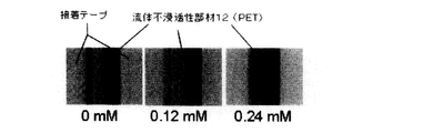
- the analyte adiponectin concentrations were 0 ng / ml, 50 ng / ml, 100 ng / ml, 200 ng / ml, and 300 ng /
- the sample was used as an ml in an assay device, and the relationship between the change in the concentration of the sample and the chemiluminescence intensity was examined.
- FIG. 15 there is a positive correlation between the concentration of adiponectin and the luminescence intensity (FIG. 15), and it is shown that the assay device of the present invention can detect a sample with high accuracy and can be applied to quantification of an unknown sample concentration. It was.
- the assay device using the porous medium of the present invention can measure a specimen in a liquid sample in a micro flow channel that is a space, and can achieve high sensitivity and high accuracy in general-purpose measurement. Useful.
Abstract
Description
本発明の別の目的は、多段階のアッセイを可能とするアッセイ装置を提供することである。
先端部を有するマイクロ流路と、
マイクロ流路の先端部の付近に配置された多孔質媒体と、
前記マイクロ流路と前記多孔質媒体の間に配置された空間部とを備え、
ラテラルフローに基づいてマイクロ流路内を移動してきた流体が、空間部を超えて多孔質媒体と接触して吸収された後に、流体がマイクロ流路内に留置されるように空間部にて分離されるように構成されている、アッセイ装置。
マイクロ流路から前記空間部へ移動した第1液体は前記空間により2つに分離されて、一方はマイクロ流路内に留置され、1つは多孔質媒体に吸収され、
次に、マイクロ流路内を移動した第2液体は、マイクロ流路内に留置されていた第1液体を多孔質媒体へ押し出し、第1液体と第2の液体が交換される項1に記載のアッセイ装置。
(ii)マイクロ流路と前記空間部の幅が同じであり、前記空間の高さはマイクロ流路の高さより大きく、かつマイクロ流路の幅に対するマイクロ流路と前記多孔質媒体との距離Bの比が0.5~5であるか、
(iii)平面視でマイクロ流路の先端部から幅方向両側にテーパ状に拡大し、テーパの終端で多孔質媒体を収容する空間部に連通するように前記空間部が形成され、かつマイクロ流路76の幅に対するマイクロ流路と多孔質媒体との距離の比が1~5であるか、
(iv)平面視でマイクロ流路の先端部から幅方向両側に略円弧状に幅方向両側にテーパ状に側面が拡大し、テーパの終端で多孔質媒体を収容する空間部に連通するように前記空間部が形成され、かつマイクロ流路の幅に対するマイクロ流路と多孔質媒体との距離の比が1~5であるか、または
(v)前記空間部が、平面視でマイクロ流路の先端部から延びマイクロ流路の幅方向の中心を通る長手方向軸の方に湾曲する第1部分と、変曲点を経て、第1部分とは反対にアッセイ装置の外側方向に湾曲して多孔質媒体を収容する空間部に連通する第2部分とを有し、かつマイクロ流路の先端部から多孔質媒体を収容する空間部に向かって幅が拡大する側面を有し、かつマイクロ流路の幅に対するマイクロ流路と多孔質媒体との距離の比が1~5である、項1~4に記載のアッセイ装置。
(1)アッセイ領域74がマイクロ流路76に存在するため、アッセイ領域が多孔質媒体に存在する従来のイムノクロマトグラフィやディップスティック法に比べ、検出感度が大幅に増大し、従来の紙製デバイスで頻発していた偽陽性・偽陰性の問題の改善が大きく期待できる。
(2)マイクロ流路76が空間であるため、多孔質媒体上を液体試料が移動する従来のイムノクロマトグラフィやディップスティック法に比べ、液体試料が一般に少量で済む。
(3)測定の感度が高く安定しているため、検体の定量も可能である。
(4)マイクロ流路76を区画形成する第1及び第2の流体不浸透性部材12,20が接触角90度以下のプラスチックの軟らかいフィルムやシートから構成されているため、ポンプ等の外部装置を使わずとも自律的なラテラルフローにより液体試料が移動できる。
(5)第1の流体不浸透性部材12及び第2の流体不浸透性部材20が透明なシート又はフィルムであるため、マイクロ流路76内のアッセイ領域74を目視で観察できる。
(6)吸収紙44の毛細管力と、液体試料の気液界面の表面張力と、バルブ機構としての空間部82が設置されている。特に、空間部82は、主としてラテラルフローに基づきマイクロ流路76内を移動してきた流体が、先端部80において空間部82内で球体に成長し、吸収紙44と接触した球体が破壊されて多孔質媒体44に吸収可能な形状及び/又は寸法に構成されている。このため、マイクロ流路内へ液体試料を「流す・止める」動作を自律的に行うことができる。さらには、複数の液体試料を連続的に繰り返して流し、多項目の測定を行うことも可能である。
(7)マイクロ流路76の側壁が接着テープ26から構成されているため、マイクロ流路76の高さを一様に容易に維持できる。また、熱圧着に比べて安価で簡便にマイクロ流路76を構成できる。
(8)流路72の基端部に、親水性多孔質媒体である展開紙42を設けたため、血漿分離紙67を通過した液体が、展開紙42からマイクロ流路76内へ確実な再現率で吸い込まれ、流動される。一般に、分離膜や微細流路を用いた血漿分離では、血球の凝集・目詰まりにより分離の流れが停止したり、またはポンプなどの強い圧力で溶血或は血球成分が混入するなどの問題が多発していたが、本構造の最適化を実現する事により、血漿分離紙67とソフトな圧力であるラテラルフローにより、全血から血漿成分だけをマイクロ流路76に確実な再現率で流動させる事ができる。
(9)流路72と外気とを隔てる穴18,70が、濡れた多孔質媒体である展開紙42及び吸収紙44でそれぞれ塞がれているため、流路72内の液体が揮発し難い。
(10)血漿分離紙67を設けたことにより全血もその場で診断できるため、疾患の早期発見、新薬の開発に対し、飛躍的な迅速化・効率化が期待できる。
(11)展開紙及び/又は前記多孔質媒体が、セルロース、ニトロセルロース、セルロースアセテート、濾紙、ティッシュペーパー、トイレットペーパー、ペーパータオル、布地、及び多孔質ポリマー等であり、市販のものを安価に入手し、簡便に使用できる。
(12)市販の安価な多孔質媒体、透明フィルム又は、接着テープ、及び紙等を用いてマイクロ流体デバイス10を非常に安価かつ簡便に作製できるため、発展途上国の病院等、これまで購入出来なかった層への展開できる他、国内及び先進国OTC市場へも展開可能でき、世界中の人々の生活の質(QOL)の向上に貢献できる。
(13)マイクロ流体デバイス10の構成要素の材料が、特に第1及び第2の流体不浸透性部材12,20の材料がプラスチック、介在部材が接着テープ26、カバー部材50及びベース部材51が紙より構成されており、このようにすべて軟らかい材料であるため、鋏やカッター等でカットし、マイクロ流路76中の試料を回収できる。このため、遺伝子解析等の次フェーズの生命科学研究支援ツールとしても活用できる。
○第1及び第2の流体不浸透性部材12,20及び介在部材のうちの少なくともいずれかが、半透明又は不透明であってもよいし、プラスチック以外に、樹脂、ガラス又は金属等、流体が浸透しない他の材料から形成されてもよい。また、第1及び第2の流体不浸透性部材12,20及び介在部材の材料は同じであっても異なっていてもよい。第1及び第2の流体不浸透性部材12,20及び介在部材の材料が異なる場合、第1の流体不浸透性部材12のみが透明な材料であってもよく、又は、第1の流体不浸透性部材12のみが軟らかいシート又はフィルムであってもよい。
○第1の流体不浸透性部材12の穴18や接着テープ64の穴66の形状や寸法は、展開紙42に通じる限り、特には限定されない。
○第1の実施形態では、空間部82の底面の高さはマイクロ流路76の底面の高さよりも低くなっていたが、空間部82の底面の高さとマイクロ流路76の底面の高さが同じでもよい。
○空間部82の形状は、第1実施形態の形状に限定されない。例えば、図7(a)~(d)の平面図及び(e)~(h)の側面図に示される種々の形状であってもよい。
○接着テープ26を初めとする介在部材は、マイクロ流路76の高さを調節するために、複数の介在部材を上下に積み重ねてもよい。また、介在部材は一つの部材に限らず、液体試料の漏れがないよう水平方向に接続された複数の部材から構成されてもよい。例えば図8に示されるように、接着テープ26を3つ積層させて貼り合わせでもよい。この場合、下の2つの接着テープ26は長手方向の途中で切れており、3つ積層させた時にこの切れ目27の箇所でマイクロ流路76の厚みを小さくすることができるが、第2の流体不浸透性部材20をPVDC等の軟らかいフィルムとすれば段差の異なる流路に対しても凹凸にあわせてカバーリングが可能である。流路内に厚みが大きくなる箇所を設けると、液体試料が粘性力により流路内に留まるための突起部ができ、その結果、流体が流路内に留まる力が強まるため、揮発の影響を低減させる事ができる。流路内の厚みを小さくすると、反応空間が狭くなるため、分子の拡散(移動)距離と拡散による混合時間が短くなるため、反応時間が大幅に短縮される。
○介在部材は接着テープ26に限定されるものではなく、マイクロ流路76や空間部82からなる流体が流動する空間部を密閉することができれば他の部材でもよい。例えば、プラスチックやフィルムなどを介在部材として用いて、流体不浸透性部材12,20と熱圧着により接合しても良いし、接着材を使って接合しても良く、表面プラズマ処理により表面改質を施して接合しても良く、両面テープだけに限定されるものではない。
○介在部材の先端部30も閉じた構造とし、介在部材全体を環状に形成し、アッセイ装置の液密性を高めてもよい。
○液体試料は血液に限られず、種々の液体試料中の様々な検体を検出できる。
○液体試料が血液でない場合、接着テープ68と血漿分離紙67は省略されてもよく、血漿分離紙67の代わりに、アッセイに好ましくない液体試料中の物質を除去するためのフィルタが設けられてもよい。
○展開紙42の代わりに、又は展開紙42に加えて、親水性処理を施すために、第2の多孔質媒体としての親水膜が流路72の基端部又はその付近に設けられてもよい。親水膜は、液体試料中の特異的結合体が流路へ非特異的に吸着するのを防ぐブロッキング剤を意味し、これにはBlock Ace等の市販のブロッキング剤、ウシ血清アルブミン、カゼイン、スキムミルク、ゼラチン、界面活性剤、ポリビニルアルコール、グロブリン、血清(例えばウシ胎仔血清又は正常ウサギ血清)、エタノール、及びMPCポリマー等が挙げられる。かかるブロッキング剤は、単独で又は2種以上を混合して用いることができる。
○カバー部材50に設けられたスリット62は、アッセイ領域74に対応する位置にありアッセイ領域74の観察が可能である限り、形状及び寸法は特に限定されない。
○カバー部材50及び/又はベース部材51は、紙以外の多孔質媒体、プラスチック、樹脂、ガラス、又は金属から形成されてもよい。
○ベース部材51にスリットを設けてもよい。例えば、発光や蛍光測定などにより検体を検出する場合、ベース部材51に図1のスリット62のようなスリットを設け、マイクロ流体デバイスを、光などを反射する鏡面やアルミ及びステンレス製の金属平板上に置いて測定を行ってもよい。
○ベース部材51の先端部52の凹部53は、吸収紙44の厚みが接着シート26以下の場合は省略されてもよい。
○第1の流体不浸透性部材12及び/又は第2の流体不浸透性部材20自体がマイクロ流体デバイス10の構成に十分な丈夫さ又は剛性を与えている場合、カバー部材50及び/又はベース部材51が省略されてもよい。
○第1の流体不浸透性部材12、第2の流体不浸透性部材20、接着テープ26、及びカバー部材50、ベース部材51は形状及び寸法を合わせているが、マイクロ流路76が確保される限り、例えばカバー部材50、ベース部材51の寸法を他の部材より大きくしてカバー部材50とベース部材51を互いに接続する等、各部材の形状及び寸法は適宜変更してもよい。
○流路72の空気抜きのための穴70は、吸収紙44の上又はその周辺で流路72と空気連通する箇所であればどこに設けられてもよく、あるいは穴70が設けられなくてもマイクロ流体デバイス10が作動する限り省略されてもよい。
○マイクロ流体デバイス10は複数の流路を備えていてもよい。例えば、図9(a),(b)の別例に示されるように、マイクロ流体デバイス10は4つの流路72を備え、4つの流路72は互いに基端で合一し、隣り合う流路72と略垂直の角度をなすよう放射状に配置される。この場合、血漿分離紙67に適用された液体試料は放射状に4つのマイクロ流路76を流れ、液体試料中の検体は各マイクロ流路76のアッセイ領域74で分析又は検出され、余分な液体試料は吸収紙44で吸収される。アッセイ領域74に異なるアッセイ試薬を配置すれば、一つの液体試料で同時に最大4つの項目が分析又は検出可能である。
○図10の別例で示されるように、マイクロ流路76は、途中に、マイクロ流路76よりも幅が広い幅拡大部94をさらに備えていてもよい。幅拡大部94をアッセイ領域74とし、例えば一次抗体等のアッセイ試薬を結合させると、マイクロ流路76の幅が一様である場合に比べて、マイクロ流路76の長さ方向に短い領域で多量の抗原及び抗体を反応させることができる。また、幅拡大部94を円形又は楕円形にすれば液体試料の流れの滞留も防止される。
バルブ機構の空間部を備えた本発明のアッセイ装置に、緩衝液5μl(0.1 M リン酸緩衝液 pH7.4)と蛍光試薬5μl(FITC溶液 10 nM)を交互に流過させ、マイクロ流路の先端から1mmの箇所に光学プローブ(No. 4040(Spot dia. : 0.4 mm、日本板硝子株式会社)を当て、光ファイバー型蛍光検出器 (FLE1100B、日本板硝子株式会社)にて蛍光強度を測定した。
本発明のアッセイ装置の仕様は以下の通りとした。
・マイクロ流路 幅1mm、長さ13mm。
・第1の流体不浸透性部材(透明フィルム)
素材:PET、寸法:35mm×12mm×0.13mm(縦×横×厚み)、入手先:EPSON
・第2の流体不浸透性部材(透明フィルム)
素材:PVDC、寸法:35mm×12mm×0.01mm(縦×横×厚み)、入手先:Asahi KASEI
・介在部材(接着テープ) 素材:A4接着転写シート(接着層25μm、フィルム層15μm、接着層25μmが順に重ね合わされたもの)、入手先:プランド産業
・カバー部材 素材:プロ紙(セルロース)、寸法:35mm×12mm×0.33mm(縦×横×厚み)、入手先:株式会社青柳
・ベース部材 0.33mmの厚紙を3枚積層させたもの。2枚は開口部34と同じ形態の開口部があり、厚みが0.5mm程度の吸収紙44が十分に収まる空間を備えている。3枚目は開口部34の空間が無い。素材:プロ紙(セルロース)、寸法:35mm×12mm×0.99mm(縦×横×厚み)、入手先:株式会社青柳
・血漿分離紙 寸法:5mm×5mm(縦×横)、入手先:日本ポール株式会社 吸収紙 寸法:8mm×10mm(縦×横)、入手先:日本製紙クレシア株式会社製ヒト被験者から採取した全血を液体試料として用い、血中のアディポネクチンを検出した。
実施例2において、物理吸着により第1の流体不浸透性部材12に一次抗体を固定した後、キットに推奨された方法で調製した二次抗体溶液にトレハロース3%を混合し、これを一次抗体を固定した位置よりも上流側(基端側)のBlock Aceの上に塗布して、1時間静置し、第1の流体不浸透性部材12にさらに二次抗体を固定した。
実施例2と同じ仕様のアッセイ装置を用いた。ただし、検体はグルコースとし、検体の検出にはFunakoshi社製のGlucose Assay Kit(100 assays)を用いた。
実施例2と同じ条件で、検体のアディポネクチンの濃度を0ng/ml、50ng/ml、100 ng/ml、200 ng/ml、及び300 ng/mlとしてアッセイ装置に供し、検体の濃度の変化と化学発光強度の関係を調べた。その結果、アディポネクチンの濃度と発光強度には正の相関があり(図15)、本発明のアッセイ装置によれば高い精度で検体を検出でき、未知の検体濃度の定量にも適用できることが示された。
Claims (11)
- アッセイ装置であって、
先端部を有するマイクロ流路と、
マイクロ流路の先端部の付近に配置された多孔質媒体と、
前記マイクロ流路と前記多孔質媒体の間に配置された空間部とを備え、
ラテラルフローに基づいてマイクロ流路内を移動してきた流体が、空間部を超えて多孔質媒体と接触して吸収された後に、流体がマイクロ流路内に留置されるように空間部にて分離されるように構成されている、アッセイ装置。 - 前記空間部の断面積は、前記マイクロ流路の断面積よりも大きい請求項1に記載のアッセイ装置。
- 前記空間部の体積は、0.001μl以上10,000μl以下であり、マイクロ流路に対する空間部の容積比が0.01以上である請求項1に記載のアッセイ装置。
- 前記流体は第1液体及び第2液体であり、
マイクロ流路から前記空間部へ移動した第1液体は前記空間により2つに分離されて、一方はマイクロ流路内に留置され、1つは多孔質媒体に吸収され、
次に、マイクロ流路内を移動した第2液体は、マイクロ流路内に留置されていた第1液体を多孔質媒体へ押し出し、第1液体と第2の液体が交換される請求項1に記載のアッセイ装置。 - (i)前記空間部の幅がマイクロ流路の幅よりも大きく、前記空間の高さはマイクロ流路の高さと同じかそれより大きく、かつマイクロ流路の幅に対するマイクロ流路と多孔質媒体との間の距離の比が0.5~5倍であるか、
(ii)マイクロ流路と前記空間部の幅が同じであり、前記空間の高さはマイクロ流路の高さより大きく、かつマイクロ流路の幅に対するマイクロ流路と前記多孔質媒体との距離Bの比が0.5~5であるか、
(iii)平面視でマイクロ流路の先端部から幅方向両側にテーパ状に拡大し、テーパの終端で多孔質媒体を収容する空間部に連通するように前記空間部が形成され、かつマイクロ流路76の幅に対するマイクロ流路と多孔質媒体との距離の比が1~5であるか、
(iv)平面視でマイクロ流路の先端部から幅方向両側に略円弧状に幅方向両側にテーパ状に側面が拡大し、テーパの終端で多孔質媒体を収容する空間部に連通するように前記空間部が形成され、かつマイクロ流路の幅に対するマイクロ流路と多孔質媒体との距離の比が1~5であるか、または
(v)前記空間部が、平面視でマイクロ流路の先端部から延びマイクロ流路の幅方向の中心を通る長手方向軸の方に湾曲する第1部分と、変曲点を経て、第1部分とは反対にアッセイ装置の外側方向に湾曲して多孔質媒体を収容する空間部に連通する第2部分とを有し、かつマイクロ流路の先端部から多孔質媒体を収容する空間部に向かって幅が拡大する側面を有し、かつマイクロ流路の幅に対するマイクロ流路と多孔質媒体との距離の比が1~5である、請求項1~4に記載のアッセイ装置。 - マイクロ流路の流体導入部に配置された第2の多孔質媒体をさらに備える請求項1に記載のアッセイ装置。
- 前記第2の多孔質媒体の上に血漿分離紙をさらに備える請求項6に記載のアッセイ装置。
- 前記マイクロ流路及び前記空間部が親水処理され、第1の多孔質媒体及び第2の多孔質媒体が親水性である請求項6に記載のアッセイ装置。
- 前記マイクロ流路、前記空間部、第1の多孔質媒体、及び第2の多孔質媒体が一対の流体不浸透性部材で挟まれている請求項1に記載のアッセイ装置。
- 前記マイクロ流路を構成する流体不浸透性部材の面が透明なシート又はフィルムである請求項9に記載のアッセイ装置。
- 流体導入部と前記空間部の間のマイクロ流路内にアッセイ試薬をさらに備える請求項1に記載のアッセイ装置。
Priority Applications (3)
| Application Number | Priority Date | Filing Date | Title |
|---|---|---|---|
| EP13841772.0A EP2902784B1 (en) | 2012-09-28 | 2013-09-27 | Assay device using porous medium |
| JP2014538621A JP6037184B2 (ja) | 2012-09-28 | 2013-09-27 | 多孔質媒体を利用したアッセイ装置 |
| US14/432,058 US9744534B2 (en) | 2012-09-28 | 2013-09-27 | Assay device using porous medium |
Applications Claiming Priority (2)
| Application Number | Priority Date | Filing Date | Title |
|---|---|---|---|
| JP2012-216840 | 2012-09-28 | ||
| JP2012216840 | 2012-09-28 |
Publications (1)
| Publication Number | Publication Date |
|---|---|
| WO2014051033A1 true WO2014051033A1 (ja) | 2014-04-03 |
Family
ID=50388427
Family Applications (1)
| Application Number | Title | Priority Date | Filing Date |
|---|---|---|---|
| PCT/JP2013/076221 WO2014051033A1 (ja) | 2012-09-28 | 2013-09-27 | 多孔質媒体を利用したアッセイ装置 |
Country Status (4)
| Country | Link |
|---|---|
| US (1) | US9744534B2 (ja) |
| EP (1) | EP2902784B1 (ja) |
| JP (1) | JP6037184B2 (ja) |
| WO (1) | WO2014051033A1 (ja) |
Cited By (12)
| Publication number | Priority date | Publication date | Assignee | Title |
|---|---|---|---|---|
| CN104764875A (zh) * | 2015-01-27 | 2015-07-08 | 北京化工大学 | 唾液样品进样微流控装置 |
| JP2015172492A (ja) * | 2014-03-11 | 2015-10-01 | 国立研究開発法人産業技術総合研究所 | 多孔質媒体を利用したアッセイ装置 |
| JP2017203763A (ja) * | 2016-05-09 | 2017-11-16 | 住友ゴム工業株式会社 | 医療用検査装置及び細胞検査方法 |
| KR20180039737A (ko) * | 2015-09-04 | 2018-04-18 | 노쓰 캐롤라이나 스테이트 유니버시티 | 미세유체 디바이스용 수동형 펌프 |
| CN109490286A (zh) * | 2018-10-23 | 2019-03-19 | 杭州光启医疗科技发展有限公司 | 用于医院检验科和泌尿科的尿液分析仪 |
| WO2019131606A1 (ja) * | 2017-12-25 | 2019-07-04 | 大日本印刷株式会社 | 検査デバイス |
| JP2019120557A (ja) * | 2017-12-28 | 2019-07-22 | 国立研究開発法人産業技術総合研究所 | アッセイ装置 |
| JP2019120556A (ja) * | 2017-12-28 | 2019-07-22 | 国立研究開発法人産業技術総合研究所 | アッセイ装置 |
| JP2019144133A (ja) * | 2018-02-21 | 2019-08-29 | 国立研究開発法人産業技術総合研究所 | アッセイ装置 |
| JP2019528430A (ja) * | 2016-08-11 | 2019-10-10 | エスアールアイ インターナショナルSRI International | 生体試料分析システム、構成要素、およびその方法 |
| US10786812B2 (en) | 2016-05-09 | 2020-09-29 | Sumitomo Rubber Industries, Ltd. | Medical analysis device and cell analysis method |
| JP7458098B2 (ja) | 2020-03-17 | 2024-03-29 | ナノエンテク インク | 流体分析用チップ |
Families Citing this family (8)
| Publication number | Priority date | Publication date | Assignee | Title |
|---|---|---|---|---|
| FR3045158A1 (fr) * | 2015-12-15 | 2017-06-16 | Imaccess | Dispositif de test immunochromatographique a flux lateral, sans effet hook |
| WO2017123668A1 (en) * | 2016-01-12 | 2017-07-20 | Trustees Of Tufts College | Separation of cells based on size and affinity using paper microfluidic device |
| US10807093B2 (en) | 2016-02-05 | 2020-10-20 | Katholieke Universiteit Leuven | Microfluidic systems |
| CN106124252B (zh) * | 2016-08-30 | 2017-10-24 | 博奥颐和健康科学技术(北京)有限公司 | 一种样品采样芯片 |
| JP7062285B2 (ja) * | 2018-07-23 | 2022-05-16 | 国立研究開発法人産業技術総合研究所 | アッセイプログラム及びアッセイ装置 |
| JP7011865B2 (ja) * | 2018-08-31 | 2022-02-10 | 国立研究開発法人産業技術総合研究所 | アッセイ装置 |
| CN108872081B (zh) * | 2018-09-04 | 2023-06-23 | 重庆科技学院 | 一种检测重金属离子的多层微流控芯片 |
| WO2023204270A1 (ja) * | 2022-04-21 | 2023-10-26 | 国立研究開発法人産業技術総合研究所 | アッセイ装置 |
Citations (9)
| Publication number | Priority date | Publication date | Assignee | Title |
|---|---|---|---|---|
| JP2002357616A (ja) * | 2001-05-31 | 2002-12-13 | Inst Of Physical & Chemical Res | 微量液体制御機構 |
| JP2004163104A (ja) * | 2001-10-18 | 2004-06-10 | Aida Eng Ltd | 微量液体秤取構造及び該構造を有するマイクロチップ |
| JP2008514966A (ja) * | 2004-09-30 | 2008-05-08 | クイデル コーポレイション | 第1及び第2流路を有する分析装置 |
| JP2009031102A (ja) * | 2007-07-26 | 2009-02-12 | Panasonic Corp | 試料分析チップ |
| JP2009162558A (ja) | 2007-12-28 | 2009-07-23 | Bio Device Technology:Kk | イムノクロマト分析法及びイムノクロマト分析キット |
| WO2009110089A1 (ja) * | 2008-03-07 | 2009-09-11 | 株式会社ティー・ワイ・エー | 体液成分の分析器具 |
| JP2009264879A (ja) | 2008-04-24 | 2009-11-12 | Japan Advanced Institute Of Science & Technology Hokuriku | ラテラルフロー型のクロマトストリップ及び生体材料の固相化方法 |
| JP2010515877A (ja) | 2006-10-18 | 2010-05-13 | プレジデント アンド フェロウズ オブ ハーバード カレッジ | パターン化多孔質媒体に基づくラテラルフロー式及びフロースルー式バイオアッセイ装置、該装置の製造方法、及び該装置の使用方法 |
| JP2012098237A (ja) | 2010-11-05 | 2012-05-24 | Japan Advanced Institute Of Science & Technology Hokuriku | イムノクロマトグラフィーにおける多段階増感操作をワンステップにする流路設計 |
Family Cites Families (8)
| Publication number | Priority date | Publication date | Assignee | Title |
|---|---|---|---|---|
| US6117394A (en) * | 1996-04-10 | 2000-09-12 | Smith; James C. | Membrane filtered pipette tip |
| CA2307499C (en) * | 1997-11-04 | 2006-08-01 | Raouf A. Guirguis | Method and apparatus for mixing and separating particulate matter from a liquid specimen |
| EP1304167B1 (en) | 2001-10-18 | 2004-07-28 | Aida Engineering Ltd. | Micro-globule metering and sampling structure and microchips having the structure |
| US7519535B2 (en) * | 2005-01-31 | 2009-04-14 | Qualcomm Incorporated | Frame erasure concealment in voice communications |
| US7871391B2 (en) * | 2005-10-21 | 2011-01-18 | Fresenius Medical Care Holdings, Inc. | Extracorporeal fluid circuit |
| SE531948C2 (sv) * | 2006-06-20 | 2009-09-15 | Aamic Ab | Analysanordning för vätskeprover innefattande filter i direkt kontakt med projektioner |
| EP2112514A1 (en) * | 2008-04-24 | 2009-10-28 | bioMérieux BV | Method and apparatus for checking the fluid in a pipet tip |
| JP6281945B2 (ja) * | 2014-03-11 | 2018-02-21 | 国立研究開発法人産業技術総合研究所 | 多孔質媒体を利用したアッセイ装置 |
-
2013
- 2013-09-27 EP EP13841772.0A patent/EP2902784B1/en active Active
- 2013-09-27 US US14/432,058 patent/US9744534B2/en active Active
- 2013-09-27 JP JP2014538621A patent/JP6037184B2/ja active Active
- 2013-09-27 WO PCT/JP2013/076221 patent/WO2014051033A1/ja active Application Filing
Patent Citations (9)
| Publication number | Priority date | Publication date | Assignee | Title |
|---|---|---|---|---|
| JP2002357616A (ja) * | 2001-05-31 | 2002-12-13 | Inst Of Physical & Chemical Res | 微量液体制御機構 |
| JP2004163104A (ja) * | 2001-10-18 | 2004-06-10 | Aida Eng Ltd | 微量液体秤取構造及び該構造を有するマイクロチップ |
| JP2008514966A (ja) * | 2004-09-30 | 2008-05-08 | クイデル コーポレイション | 第1及び第2流路を有する分析装置 |
| JP2010515877A (ja) | 2006-10-18 | 2010-05-13 | プレジデント アンド フェロウズ オブ ハーバード カレッジ | パターン化多孔質媒体に基づくラテラルフロー式及びフロースルー式バイオアッセイ装置、該装置の製造方法、及び該装置の使用方法 |
| JP2009031102A (ja) * | 2007-07-26 | 2009-02-12 | Panasonic Corp | 試料分析チップ |
| JP2009162558A (ja) | 2007-12-28 | 2009-07-23 | Bio Device Technology:Kk | イムノクロマト分析法及びイムノクロマト分析キット |
| WO2009110089A1 (ja) * | 2008-03-07 | 2009-09-11 | 株式会社ティー・ワイ・エー | 体液成分の分析器具 |
| JP2009264879A (ja) | 2008-04-24 | 2009-11-12 | Japan Advanced Institute Of Science & Technology Hokuriku | ラテラルフロー型のクロマトストリップ及び生体材料の固相化方法 |
| JP2012098237A (ja) | 2010-11-05 | 2012-05-24 | Japan Advanced Institute Of Science & Technology Hokuriku | イムノクロマトグラフィーにおける多段階増感操作をワンステップにする流路設計 |
Non-Patent Citations (1)
| Title |
|---|
| See also references of EP2902784A4 |
Cited By (19)
| Publication number | Priority date | Publication date | Assignee | Title |
|---|---|---|---|---|
| JP2015172492A (ja) * | 2014-03-11 | 2015-10-01 | 国立研究開発法人産業技術総合研究所 | 多孔質媒体を利用したアッセイ装置 |
| CN104764875A (zh) * | 2015-01-27 | 2015-07-08 | 北京化工大学 | 唾液样品进样微流控装置 |
| CN104764875B (zh) * | 2015-01-27 | 2016-08-17 | 北京化工大学 | 唾液样品进样微流控装置 |
| KR102639604B1 (ko) * | 2015-09-04 | 2024-02-23 | 노쓰 캐롤라이나 스테이트 유니버시티 | 미세유체 디바이스용 수동형 펌프 |
| KR20180039737A (ko) * | 2015-09-04 | 2018-04-18 | 노쓰 캐롤라이나 스테이트 유니버시티 | 미세유체 디바이스용 수동형 펌프 |
| JP2018529538A (ja) * | 2015-09-04 | 2018-10-11 | ノース カロライナ ステート ユニバーシティ | マイクロ流体デバイスのためのパッシブ型ポンプ |
| JP2021063831A (ja) * | 2015-09-04 | 2021-04-22 | ノース カロライナ ステート ユニバーシティ | マイクロ流体デバイスのためのパッシブ型ポンプ |
| US10946378B2 (en) | 2015-09-04 | 2021-03-16 | North Carolina State University | Passive pumps for microfluidic devices |
| US10786812B2 (en) | 2016-05-09 | 2020-09-29 | Sumitomo Rubber Industries, Ltd. | Medical analysis device and cell analysis method |
| JP2017203763A (ja) * | 2016-05-09 | 2017-11-16 | 住友ゴム工業株式会社 | 医療用検査装置及び細胞検査方法 |
| JP2019528430A (ja) * | 2016-08-11 | 2019-10-10 | エスアールアイ インターナショナルSRI International | 生体試料分析システム、構成要素、およびその方法 |
| WO2019131606A1 (ja) * | 2017-12-25 | 2019-07-04 | 大日本印刷株式会社 | 検査デバイス |
| JP2019120556A (ja) * | 2017-12-28 | 2019-07-22 | 国立研究開発法人産業技術総合研究所 | アッセイ装置 |
| JP2019120557A (ja) * | 2017-12-28 | 2019-07-22 | 国立研究開発法人産業技術総合研究所 | アッセイ装置 |
| JP2019144133A (ja) * | 2018-02-21 | 2019-08-29 | 国立研究開発法人産業技術総合研究所 | アッセイ装置 |
| JP7016152B2 (ja) | 2018-02-21 | 2022-02-04 | 国立研究開発法人産業技術総合研究所 | アッセイ装置 |
| CN109490286A (zh) * | 2018-10-23 | 2019-03-19 | 杭州光启医疗科技发展有限公司 | 用于医院检验科和泌尿科的尿液分析仪 |
| CN109490286B (zh) * | 2018-10-23 | 2021-08-17 | 焦占峰 | 用于医院检验科和泌尿科的尿液分析仪 |
| JP7458098B2 (ja) | 2020-03-17 | 2024-03-29 | ナノエンテク インク | 流体分析用チップ |
Also Published As
| Publication number | Publication date |
|---|---|
| EP2902784B1 (en) | 2018-10-24 |
| US9744534B2 (en) | 2017-08-29 |
| JP6037184B2 (ja) | 2016-12-07 |
| JPWO2014051033A1 (ja) | 2016-08-22 |
| EP2902784A4 (en) | 2016-04-20 |
| US20150266023A1 (en) | 2015-09-24 |
| EP2902784A1 (en) | 2015-08-05 |
Similar Documents
| Publication | Publication Date | Title |
|---|---|---|
| JP6037184B2 (ja) | 多孔質媒体を利用したアッセイ装置 | |
| US10159978B2 (en) | Flow control in microfluidic systems | |
| JP6281945B2 (ja) | 多孔質媒体を利用したアッセイ装置 | |
| US8101403B2 (en) | Method and device for rapid parallel microfluidic molecular affinity assays | |
| US7858384B2 (en) | Flow control technique for assay devices | |
| ES2949146T3 (es) | Dispositivo de ensayo lateral | |
| US20150290639A1 (en) | Pressure assisted lateral flow diagnostic device | |
| WO2006047831A1 (en) | Detection device and method | |
| US20090087925A1 (en) | Devices and methods for analysis of samples with depletion of analyte content | |
| US9079179B2 (en) | Microfluidic device comprising sensor | |
| KR101813162B1 (ko) | 필름-기반 미세유체 디바이스 및 이를 이용한 바이오센서 | |
| JP2003114229A (ja) | マイクロチャネルチップ,マイクロチャネルチップを使用した測定装置及び測定方法 | |
| US20210170398A1 (en) | Assay device | |
| US20190001332A1 (en) | Disposable independent 3-d structure depened sequential capillary lateral flow device for analyte determination | |
| KR102007164B1 (ko) | 다중 미세유로를 구비한 하이브리드 신속 진단 키트 | |
| WO2019131606A1 (ja) | 検査デバイス | |
| JP2007519896A (ja) | システム | |
| JP7016152B2 (ja) | アッセイ装置 | |
| WO2022149518A1 (ja) | アッセイ装置 | |
| JP7062285B2 (ja) | アッセイプログラム及びアッセイ装置 | |
| JP6950955B2 (ja) | アッセイ装置 | |
| JP2004125545A (ja) | 分析方法及び装置 |
Legal Events
| Date | Code | Title | Description |
|---|---|---|---|
| 121 | Ep: the epo has been informed by wipo that ep was designated in this application |
Ref document number: 13841772 Country of ref document: EP Kind code of ref document: A1 |
|
| ENP | Entry into the national phase |
Ref document number: 2014538621 Country of ref document: JP Kind code of ref document: A |
|
| WWE | Wipo information: entry into national phase |
Ref document number: 14432058 Country of ref document: US Ref document number: 2013841772 Country of ref document: EP |
|
| NENP | Non-entry into the national phase |
Ref country code: DE |