WO2014050502A1 - 燃料噴射弁 - Google Patents
燃料噴射弁 Download PDFInfo
- Publication number
- WO2014050502A1 WO2014050502A1 PCT/JP2013/074078 JP2013074078W WO2014050502A1 WO 2014050502 A1 WO2014050502 A1 WO 2014050502A1 JP 2013074078 W JP2013074078 W JP 2013074078W WO 2014050502 A1 WO2014050502 A1 WO 2014050502A1
- Authority
- WO
- WIPO (PCT)
- Prior art keywords
- valve
- fuel
- valve body
- fixed core
- rear end
- Prior art date
- Legal status (The legal status is an assumption and is not a legal conclusion. Google has not performed a legal analysis and makes no representation as to the accuracy of the status listed.)
- Ceased
Links
Images



Classifications
-
- F—MECHANICAL ENGINEERING; LIGHTING; HEATING; WEAPONS; BLASTING
- F02—COMBUSTION ENGINES; HOT-GAS OR COMBUSTION-PRODUCT ENGINE PLANTS
- F02M—SUPPLYING COMBUSTION ENGINES IN GENERAL WITH COMBUSTIBLE MIXTURES OR CONSTITUENTS THEREOF
- F02M21/00—Apparatus for supplying engines with non-liquid fuels, e.g. gaseous fuels stored in liquid form
- F02M21/02—Apparatus for supplying engines with non-liquid fuels, e.g. gaseous fuels stored in liquid form for gaseous fuels
- F02M21/0218—Details on the gaseous fuel supply system, e.g. tanks, valves, pipes, pumps, rails, injectors or mixers
- F02M21/0248—Injectors
- F02M21/0257—Details of the valve closing elements, e.g. valve seats, stems or arrangement of flow passages
- F02M21/026—Lift valves, i.e. stem operated valves
- F02M21/0263—Inwardly opening single or multi nozzle valves, e.g. needle valves
- F02M21/0266—Hollow stem valves; Piston valves; Stems having a spherical tip
-
- F—MECHANICAL ENGINEERING; LIGHTING; HEATING; WEAPONS; BLASTING
- F02—COMBUSTION ENGINES; HOT-GAS OR COMBUSTION-PRODUCT ENGINE PLANTS
- F02M—SUPPLYING COMBUSTION ENGINES IN GENERAL WITH COMBUSTIBLE MIXTURES OR CONSTITUENTS THEREOF
- F02M51/00—Fuel-injection apparatus characterised by being operated electrically
- F02M51/06—Injectors peculiar thereto with means directly operating the valve needle
- F02M51/061—Injectors peculiar thereto with means directly operating the valve needle using electromagnetic operating means
- F02M51/0625—Injectors peculiar thereto with means directly operating the valve needle using electromagnetic operating means characterised by arrangement of mobile armatures
- F02M51/0664—Injectors peculiar thereto with means directly operating the valve needle using electromagnetic operating means characterised by arrangement of mobile armatures having a cylindrically or partly cylindrically shaped armature, e.g. entering the winding; having a plate-shaped or undulated armature entering the winding
- F02M51/0671—Injectors peculiar thereto with means directly operating the valve needle using electromagnetic operating means characterised by arrangement of mobile armatures having a cylindrically or partly cylindrically shaped armature, e.g. entering the winding; having a plate-shaped or undulated armature entering the winding the armature having an elongated valve body attached thereto
- F02M51/0682—Injectors peculiar thereto with means directly operating the valve needle using electromagnetic operating means characterised by arrangement of mobile armatures having a cylindrically or partly cylindrically shaped armature, e.g. entering the winding; having a plate-shaped or undulated armature entering the winding the armature having an elongated valve body attached thereto the body being hollow and its interior communicating with the fuel flow
-
- F—MECHANICAL ENGINEERING; LIGHTING; HEATING; WEAPONS; BLASTING
- F02—COMBUSTION ENGINES; HOT-GAS OR COMBUSTION-PRODUCT ENGINE PLANTS
- F02M—SUPPLYING COMBUSTION ENGINES IN GENERAL WITH COMBUSTIBLE MIXTURES OR CONSTITUENTS THEREOF
- F02M61/00—Fuel-injectors not provided for in groups F02M39/00 - F02M57/00 or F02M67/00
- F02M61/16—Details not provided for in, or of interest apart from, the apparatus of groups F02M61/02 - F02M61/14
- F02M61/18—Injection nozzles, e.g. having valve seats; Details of valve member seated ends, not otherwise provided for
- F02M61/1853—Orifice plates
-
- F—MECHANICAL ENGINEERING; LIGHTING; HEATING; WEAPONS; BLASTING
- F02—COMBUSTION ENGINES; HOT-GAS OR COMBUSTION-PRODUCT ENGINE PLANTS
- F02M—SUPPLYING COMBUSTION ENGINES IN GENERAL WITH COMBUSTIBLE MIXTURES OR CONSTITUENTS THEREOF
- F02M61/00—Fuel-injectors not provided for in groups F02M39/00 - F02M57/00 or F02M67/00
- F02M61/16—Details not provided for in, or of interest apart from, the apparatus of groups F02M61/02 - F02M61/14
- F02M61/18—Injection nozzles, e.g. having valve seats; Details of valve member seated ends, not otherwise provided for
- F02M61/1886—Details of valve seats not covered by groups F02M61/1866 - F02M61/188
-
- Y—GENERAL TAGGING OF NEW TECHNOLOGICAL DEVELOPMENTS; GENERAL TAGGING OF CROSS-SECTIONAL TECHNOLOGIES SPANNING OVER SEVERAL SECTIONS OF THE IPC; TECHNICAL SUBJECTS COVERED BY FORMER USPC CROSS-REFERENCE ART COLLECTIONS [XRACs] AND DIGESTS
- Y02—TECHNOLOGIES OR APPLICATIONS FOR MITIGATION OR ADAPTATION AGAINST CLIMATE CHANGE
- Y02T—CLIMATE CHANGE MITIGATION TECHNOLOGIES RELATED TO TRANSPORTATION
- Y02T10/00—Road transport of goods or passengers
- Y02T10/10—Internal combustion engine [ICE] based vehicles
- Y02T10/30—Use of alternative fuels, e.g. biofuels
Definitions
- the present invention relates to a nozzle member having a nozzle hole and a valve seat, a cylindrical valve housing connected to the rear end of the nozzle member, a fixed core connected to the rear end of the valve housing, and the valve A valve body accommodated in the housing and opening and closing the nozzle hole in cooperation with the valve seat, a linkage connected to the rear end of the valve body, and a fixed end connected to the rear end of the linkage
- a valve assembly comprising a movable core facing the front end of the core, a return spring that is compressed between the fixed core and the valve assembly and biases the valve body toward the valve closing side, and surrounds the fixed core
- a coil for opening the valve element by attracting the movable core to the fixed core by the generated magnetic force when energized, and a fuel supply section between the linkage and the valve housing.
- a fuel chamber communicating with the valve body and the valve housing. Between ring during opening of the valve body, an improvement of a fuel injection valve provided with outer fuel passage communicating the fuel chamber to the
- the present invention has been made in view of such circumstances, and can increase the fuel injection amount by increasing the fuel flow path around the valve body without increasing the valve opening stroke.
- An object of the present invention is to provide the fuel injection valve.
- the present invention provides a nozzle member having a nozzle hole and a valve seat, a cylindrical valve housing connected to the rear end of the nozzle member, and a rear end of the valve housing.
- a fixed core a valve body housed in the valve housing and opening / closing the nozzle hole in cooperation with the valve seat, a linkage connected to a rear end of the valve body, and a back of the linkage
- a valve assembly comprising a movable core connected to the end and facing the front end of the fixed core, and a return spring that is contracted between the fixed core and the valve assembly and biases the valve body toward the valve closing side
- a coil that is disposed so as to surround the fixed core and opens the valve body by attracting the movable core to the fixed core by a generated magnetic force when energized.
- a fuel chamber communicating with the fuel supply unit is provided between the valve housings.
- the valve body In the fuel injection valve having an outer fuel passage that communicates the fuel chamber with the nozzle hole between the valve body and the valve housing when the valve body is opened, the valve body is opened in the valve body.
- a first feature is that when the valve is provided, an inner fuel passage is provided in parallel with the outer fuel passage to connect the fuel chamber to the nozzle hole.
- the outer peripheral surface of the front end of the linkage is fitted and connected to the inner peripheral surface of the annular valve body, and the inner peripheral surface of the valve body and the communication surface are connected.
- a second feature is that at least one of the outer peripheral surfaces of the rod is provided with a notch communicating between the fuel chamber and the inner fuel passage.
- the fuel chamber and the nozzle hole on the outer periphery of the connection communicate with each other via the mutually parallel inner and outer fuel passages provided inside and outside the valve body.
- the fuel injection amount from the nozzle hole can be easily increased without increasing the valve opening stroke of the valve body, and the engine output can be increased.
- the valve opening stroke since there is no need to increase the valve opening stroke, it is possible to avoid an increase in the size of the coil and thus the fuel injection valve, and it is possible to suppress an increase in power consumption of the coil.
- the fuel chamber and the inner fuel passage are communicated with each other by a simple structure in which a notch is provided on at least one of the inner peripheral surface and the outer peripheral surface of the valve body and the connecting portion.
- a notch is provided on at least one of the inner peripheral surface and the outer peripheral surface of the valve body and the connecting portion.
- FIG. 1 is a longitudinal sectional view of a gas fuel injection valve according to a first embodiment of the present invention.
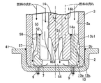
- FIG. 2 is an enlarged view of part 2 of FIG. 1 (however, the valve is opened).
- (First embodiment) 3 is a cross-sectional view taken along line 3-3 of FIG.
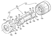
- FIG. 4 is an exploded perspective view of the valve assembly in FIG.
- FIG. 5 is a view corresponding to FIG. 2, showing a second embodiment of the present invention.
- FIG. 6 is a view corresponding to FIG. 5 showing a third embodiment of the present invention.
- hird embodiment is a longitudinal sectional view of a gas fuel injection valve according to a first embodiment of the present invention.
- FIG. 2 is an enlarged view of part 2 of FIG. 1 (however, the valve is opened).
- (First embodiment) 3 is a cross-sectional view taken along line 3-3 of FIG.
- FIG. 4 is an exploded perspective view of the valve assembly in FIG.
- FIG. 5 is a view corresponding to
- the nozzle member side is referred to as the front
- the fuel inlet cylinder side is referred to as the rear.
- the gas fuel injection valve I has a front end portion attached to a mounting hole Ea provided in the pipe wall of the intake pipe E of the engine, and gas fuel is introduced into the intake pipe E during the intake stroke of the engine. Spray.
- a valve body 1 of the injection valve I includes a cap-shaped nozzle member 2 and a hollow cylindrical valve made of a magnetic material that is joined by welding or the like by fitting the front end portion to the inner peripheral surface of the nozzle member 2.
- the fixed core 5 has a front end portion that has a front end surface as an attraction surface 5 a and is inserted into the nonmagnetic cylindrical body 4.
- the nozzle member 2 is provided with a flat valve seat 7 and a plurality of nozzle holes 9, 9... Arranged on a predetermined circumference C (see FIG. 3) in the valve seat 7.
- a central portion of the fixed core 5 is provided with a rear spring accommodating hole 19 and a retainer press-fitting hole 18 having a diameter larger than that of the rear spring accommodating hole 19, and an inner periphery of the retainer press-fitting hole 18.
- a pipe-like spring retainer 36 having a hollow portion 36a on the surface is press-fitted and fixed.
- the spring retainer 36 is provided with a single slit 37, whereby the spring retainer 36 can be elastically reduced in diameter, and the outer diameter of the spring retainer 36 has an allowance for press-fitting into the retainer press-fitting hole 18.
- the inner diameter of the retainer press-fitting hole 18 is set larger than the inner diameter in a free state.
- a rear spring seat 35 is constituted by the front end face of the spring retainer 36.
- a hollow portion 6 a of the fuel inlet cylinder 6 having a larger diameter is connected to the rear end of the soot retainer press-fitting hole 18, and a fuel filter 38 is attached to the inlet of the fuel inlet cylinder 6.
- the inner peripheral surface of the valve housing 3 is a sliding guide surface 3a, and the valve assembly 10 is fitted to the sliding guide surface 3a.
- the valve assembly 10 is slidably fitted to the sliding guide surface 3 a and has a cylindrical movable core 12 whose rear end face is opposed to the suction surface 5 a at the front end of the fixed core 5, and the valve seat 7. It is comprised by the valve body 13 which act
- a predetermined gap corresponding to the valve opening stroke of the valve body 13 is set between the opposed surfaces of the fixed core 5 and the movable core 12 when the valve body 13 is seated on the valve seat 7.
- the movable core 12 has a front spring accommodation hole 30 aligned coaxially with the rear spring accommodation hole 19 of the fixed core 5 at the center thereof, and a connecting cylinder portion 12a at the front end thereof.
- the valve body 13 generally has a hollow cylindrical shape, and includes an annular valve portion 13a facing the valve seat 7 and a connecting cylinder portion 13b integrally connected to the rear end of the valve portion 13a.
- the part 13a opens and closes the nozzle holes 9, 9 ... by being separated from and seated on the valve seat 7.
- the connecting cylinder portion 13b has a flange-like journal portion 13b1 on the outer periphery thereof that is slidably fitted to the sliding guide surface 3a.
- the connecting cylinder portion 13b is provided with a plurality of first notches 50, 50,... That open to the inner peripheral surface, the outer peripheral surface, and the rear end surface.
- the connecting rod 14 is composed of a pair of front and rear cylindrical connecting ends 14a and 14a and a connecting flange 14b integrally connecting the connecting ends 14a and 14a. There is no.
- One of the connecting end portions 14a is fitted to the inner peripheral surface of the connecting cylindrical portion 12a of the movable core 12 and connected by welding or the like, and the other connecting cylindrical portion 14a is connected to the inner periphery of the connecting cylindrical portion 13b of the valve body 13. Fitting to the surface and joining by welding or the like. In this way, the movable core 12, the linkage 14, and the valve body 13 are integrally coupled.
- Each connecting end 14 a of the linkage 14 has a circular recess 51 that opens to its end surface, a plurality of second notches 52 that open the recess 51 to the outer peripheral surface, and protrudes from the bottom surface of the recess 51. And a conical guide protrusion 53 is provided. Further, on the outer periphery of the flange portion 14b, a plurality of longitudinal grooves 54, 54... Communicating between the second notches 52, 52 of the front and rear connection end portions 14a, 14a are provided. A part of the rear end face of the rear connecting end portion 14 a fitted to the connecting cylindrical portion 12 a of the movable core 12 constitutes an annular front spring seat 34 that faces the front spring accommodating hole 30 of the movable core 12. Further, the front connecting end portion 14a and the connecting cylinder portion 13b of the valve body 13 are fitted so that the phases of the first and second notches 50 and 52 coincide with each other.
- the first notch 50 has a bottom surface 50a facing the fuel chamber 55 in the axial direction.
- the hollow portion of the valve portion 13a serves as an inner fuel passage 56, and communicates with the nozzle holes 9, 9 when the valve portion 13a is separated from the valve seat 7.
- the inner fuel passage 56 communicates with the recess 51 and the second notches 52, 52... Of the front connection end 14a.
- the valve housing 3 is provided with an enlarged diameter portion 3b facing the front portion of the valve body 13 from the journal portion 13b1 between the inner circumference surface of the enlarged diameter portion 3b and the valve body 13. Is formed with an outer fuel passage 57 communicating with the first notches 50, 50.
- a return spring 33 disposed in the rear and front spring accommodating holes 19 and 30 is contracted between the front spring seat 34 and the rear spring seat 35 with a predetermined set load.
- the load urges the valve body 13 in the valve closing direction, that is, in the seating direction on the valve seat 7.
- the set load is adjusted by the press-fitting depth of the spring retainer 36 into the retainer press-fitting hole 18.
- a coil assembly 20 is disposed from the region where the movable core 12 of the soot valve housing 3 is fitted to the fixed core 5 and surrounding them.
- the coil assembly 20 includes a valve housing 3, a bobbin 21 fitted to the outer periphery of the nonmagnetic cylindrical body 4 and the fixed core 5, and a coil 22 wound around the outer periphery of the bobbin 21.
- a magnetic coil housing 23 is disposed on the outer periphery of the solid 20 to cover it.
- a yoke flange 24 that protrudes from the outer peripheral surface and supports the rear end surface of the bobbin 21 is integrally formed on the collar fixing core 5, and the rear end portion of the coil housing 23 is fitted to the outer peripheral surface of the yoke flange 24. Further, an annular end wall 23a abutting against the front end surface of the bobbin 21 and a forward projection from the inner peripheral end of the annular end wall 23a are fitted and fixed to the outer peripheral surface of the valve housing 3 at the front end portion of the coil housing 23.
- the cylindrical portion 23b is integrally formed.
- a resin mold layer 26 that continuously covers them is formed on the outer peripheral surfaces of the coil housing 23 and the fuel inlet cylinder 6, and a coupler 28 that projects to one side is integrally formed on the resin mold layer 26.
- the molded coupler 28 holds a current-carrying terminal 27 connected to the coil 22.
- a pair of front and rear flanges 41 and 42 that define an annular front seal groove 40 are formed on the outer periphery of the nozzle member 2, and the nozzle member 2 is attached to a mounting hole for an intake pipe E of the engine in the front seal groove 40.
- a seal member 43 that is in close contact with the inner peripheral surface thereof is mounted.
- An annular rear seal groove 45 is defined on the outer periphery of the rear end portion of the fuel inlet tube 6, and the inner periphery of the fuel distribution pipe D fitted to the rear end portion of the fuel inlet tube 6 is formed in the rear seal groove 45.
- a seal member 47 that is in close contact with the surface is attached.
- valve assembly 10 In the demagnetized state of the coil 22, the valve assembly 10 is pressed forward by the set load of the return spring 33 and the valve body 13 is seated on the valve seat 7 as shown in FIG. 1.
- the magnetic flux generated by the coil 22 sequentially travels through the coil housing 23, the valve housing 3, the movable core 12, the fixed core 5, and the coil housing 23, and the magnetic force generated between the fixed core 5 and the movable core 12
- the valve assembly 10 is attracted to the suction surface 5 a of the fixed core 5 against the set load of the return spring 33, the valve body 13 is separated from the valve seat 7, and the nozzle holes 9, 9 ...open.
- the gas fuel sent from the gas fuel tank (not shown) to the fuel distribution pipe D flows into the fuel inlet cylinder 6 and is filtered by the fuel filter 38, and the hollow portion 36a of the spring retainer 36 is obtained.
- the gas fuel that has flowed into the rear recess 51 is deflected in the radial direction by the conical guide protrusion 53 protruding from the bottom surface of the recess 51, so that a plurality of second notches 52, 52.
- the gas fuel does not stagnate at the bottom of the recess 51.
- the gas fuel moved from the recess 51 to the fuel chamber 55 in the valve housing 3 flows forward, and a part of the fuel hits the bottom surfaces 50a of the plurality of first notches 50, 50.
- the fuel flows into the inner and outer fuel passages 56 and 57 substantially evenly, and the other fuel flows along the longitudinal grooves 54, 54... Of the linkage 14 and passes through the second notches 52, 52. Then, it flows into the inner fuel passage 56 inside the valve portion 13a.
- the gas fuel flowing down the bottom surfaces of the longitudinal grooves 54, 54... Can be guided into the lower conical guide protrusion 53 and smoothly flow into the recess 51. In this way, the gas fuel that has been diverted from the fuel chamber 55 into the inner and outer fuel passages 56, 57 is injected into the intake pipe E of the engine through the plurality of nozzle holes 9, 9.
- the fuel chamber 55 on the outer periphery of the linkage 14 and the nozzle holes 9, 9... The fuel flow path around the valve body 13 is enlarged, and the fuel injection amount from the nozzle holes 9, 9... Can be easily increased without particularly increasing the valve opening stroke of the valve body 13. It can be increased to meet the higher engine output. Further, since it is not necessary to increase the valve opening stroke of the valve body 13, it is possible to avoid an increase in the size of the coil 22, and hence the injection valve I, and to suppress an increase in power consumption of the coil 22.
- the inner and outer fuel passages 56 and 57 are provided at the rear end portion of the valve body 13 and open to the inner peripheral surface, the outer peripheral surface and the rear end surface thereof, and the inner peripheral surface of the valve body 13.
- the valve body 13 and the connecting rod 14 are fitted to each other through the second notch 52 provided at the connecting end portion 14a of the front portion of the connecting rod 14 fitted and connected to the fuel chamber 55.
- the fuel can be smoothly diverted from the fuel chamber 55 to the inner and outer fuel passages 56 and 57 without being interrupted by the joint.
- the individual manufacture of the valve body 13 and the linkage 14 can be facilitated, and the first and second notches 50 and 52 can be formed at the time of manufacture, so that productivity can be improved.
- the first notch 50 has a bottom surface 50a for diverting the fuel received from the fuel chamber 55 to the inner and outer fuel passages 56 and 57, so that the fuel flowing down from the fuel chamber 55 to the first notch
- the bottom surface of the notch 50 allows a substantially uniform flow to the inner and outer fuel passages, thereby equalizing the fuel flow rate from the inner and outer fuel passages 56 and 57 to the nozzle holes 9 and increasing the fuel injection amount. Can be made easier.
- FIG. 5 Next, a second embodiment of the present invention shown in FIG. 5 will be described.
- the connecting cylinder portion 13b of the valve body 13 has a cylindrical shape that is welded by fitting the inner peripheral surface to the outer peripheral surface of the front connecting end portion 14a without any breaks.
- a plurality of notches 58, 58... Communicating the fuel chamber 55 with the outer fuel passage 57 are formed on the outer peripheral surface of the cylinder portion 13b, and the inner fuel passage 56 in the valve portion 13a is connected to the outer periphery of the front connecting end portion 14a.
- the communication structure between the fuel chamber 55 and the inner fuel passage 56 is simplified, and the connecting cylinder portion 13b of the valve body 13 has a continuous inner peripheral surface and is not connected to the front connecting end portion 14a. High rigidity can be secured by fitting and fixing to the outer peripheral surface.
- connection end portion 14a at the front portion of the linkage 14 is not provided with a notch, and the fuel chamber 55 is disposed on the inner peripheral surface of the connection cylinder portion 13b of the valve body 13 fitted therein. Notches 59, 59... Communicating with the passage 56 are formed. Since the other configuration is the same as that of the second embodiment, portions corresponding to those of the second embodiment are denoted by the same reference numerals in FIG.
- the communication structure between the fuel chamber 55 and the inner fuel passage 56 is simplified, and the connecting cylinder portion 13b of the valve body 13 has no circumferential cut, so that high rigidity can be obtained. it can.
- the present invention is not limited to the embodiments described above, and various design changes can be made without departing from the scope of the invention.
- the present invention can be applied to an injection valve for liquid fuel such as gasoline.
Landscapes
- Engineering & Computer Science (AREA)
- Chemical & Material Sciences (AREA)
- Chemical Kinetics & Catalysis (AREA)
- General Chemical & Material Sciences (AREA)
- Oil, Petroleum & Natural Gas (AREA)
- Combustion & Propulsion (AREA)
- Mechanical Engineering (AREA)
- General Engineering & Computer Science (AREA)
- Fuel-Injection Apparatus (AREA)
Abstract
燃料噴射弁において、弁座(7)と協働してノズル孔(9)を開閉する弁体(13),この弁体(13)の後端に連結される連杆(14),並びにこの連杆(14)の後端に連結されて,固定コア(5)の前端に対向する可動コア(12)よりなる弁組立体(10)と,固定コア(5)を囲繞するように配設され,通電により可動コア(12)を固定コア(5)に吸引させて弁体(13)を開弁するコイル(22)とを備えてなり,連杆(14)及び弁ハウジング(3)間に,燃料供給部に連通する燃料室(55)を設け,弁体(13)及び弁ハウジング(3)間に,弁体(13)の開弁時,燃料室(55)をノズル孔(9)に連通する外側燃料通路(57)を設けた燃料噴射弁において,弁体(13)内に,弁体(13)の開弁時,外側燃料通路(57)と並列して燃料室(55)をノズル孔(9)に連通する内側燃料通路(56)を設けた。これにより弁体の開弁ストロークを増加させなくても,弁体周りの燃料流路の拡大を可能にして,燃料噴射量を増加させ得るようにする。
Description
本発明は,ノズル孔及び弁座を有するノズル部材と,このノズル部材の後端に連設される筒状の弁ハウジングと,この弁ハウジングの後端に連設される固定コアと,前記弁ハウジング内に収容され,前記弁座と協働して前記ノズル孔を開閉する弁体,この弁体の後端に連結される連杆,並びにこの連杆の後端に連結されて,前記固定コアの前端に対向する可動コアよりなる弁組立体と,前記固定コア及び前記弁組立体間に縮設されて前記弁体を閉弁側に付勢する戻しスプリングと,前記固定コアを囲繞するように配設され,通電時,発生磁力により前記可動コアを前記固定コアに吸引させて前記弁体を開弁するコイルとを備えてなり,前記連杆及び前記弁ハウジング間に,燃料供給部に連通する燃料室を設け,また前記弁体及び前記弁ハウジング間に,前記弁体の開弁時,前記燃料室を前記ノズル孔に連通する外側燃料通路を設けた燃料噴射弁の改良に関する。
かゝる燃料噴射弁は,下記特許文献1に開示されるように既に知られている。
かゝる燃料噴射弁では,弁体の開弁時,弁体外周の外側燃料室の燃料が,弁体及び弁座間に形成される流路を経てノズル孔から噴射される。ところで,エンジンの高出力化に伴ない,燃料噴射量増の要請があり,それに応えるために,弁体の開弁ストロークを大きく設定して,弁体及び弁座間の燃料流路を広げることが考えられるが,そうすることは,コイルの容量増大,延いては燃料噴射弁の大型化のみならず,コイルの消費電力の増加を招くことになって好ましくない。
本発明は,かゝる事情に鑑みてなされたもので,弁体の開弁ストロークを増加させることなく,弁体周りの燃料流路の拡大を可能にして,燃料噴射量を増加させ得るようにした前記燃料噴射弁を提供することを目的とする。
上記目的を達成するために,本発明は,ノズル孔及び弁座を有するノズル部材と,このノズル部材の後端に連設される筒状の弁ハウジングと,この弁ハウジングの後端に連設される固定コアと,前記弁ハウジング内に収容され,前記弁座と協働して前記ノズル孔を開閉する弁体,この弁体の後端に連結される連杆,並びにこの連杆の後端に連結されて,前記固定コアの前端に対向する可動コアよりなる弁組立体と,前記固定コア及び前記弁組立体間に縮設されて前記弁体を閉弁側に付勢する戻しスプリングと,前記固定コアを囲繞するように配設され,通電時,発生磁力により前記可動コアを前記固定コアに吸引させて前記弁体を開弁するコイルとを備えてなり,前記連杆及び前記弁ハウジング間に,燃料供給部に連通する燃料室を設け,また前記弁体及び前記弁ハウジング間に,前記弁体の開弁時,前記燃料室を前記ノズル孔に連通する外側燃料通路を設けた燃料噴射弁において,前記弁体内に,前記弁体の開弁時,前記外側燃料通路と並列して前記燃料室を前記ノズル孔に連通する内側燃料通路を設けたことを第1の特徴とする。
また本発明は,第1の特徴に加えて,環状の前記弁体の内周面に前記連杆の前端部の外周面を嵌合して連結し,前記弁体の内周面及び前記連杆の外周面の少なくとも一方に,前記燃料室及び内側燃料通路間を連通する切欠きを設けたことを第2の特徴とする。
本発明の第1の特徴によれば,連杆外周の燃料室とノズル孔とは,弁体の内側及び外側に設けられる互いに並列の内側及び外側燃料通路を介して連通するので,弁体周りの燃料流路が拡大することになり,弁体の開弁ストロークを増加させることなく,ノズル孔からの燃料噴射量を容易に増加させ得て,エンジンの高出力化に応えることができる。また弁体の開弁ストロークの増加の必要がないことから,コイル,延いては燃料噴射弁の大型化を避けることができ,またコイルの消費電力の増加をも抑えることができる。
本発明の第2の特徴によれば,弁体及び連杆の互いに嵌合する内周面及び外周面の少なくとも一方に切欠きを設けるという簡単な構造により,燃料室及び内側燃料通路間を連通させ,燃料室から内側燃料通路へ燃料をスムーズに移動させることができる。
I・・・・・燃料噴射弁(ガス燃料用噴射弁)
2・・・・・ノズル部材
3・・・・・弁ハウジング
5・・・・・固定コア
7・・・・・弁座
9・・・・・ノズル孔
10・・・・弁組立体
12・・・・可動コア
13・・・・弁体
14・・・・連杆
22・・・・コイル
33・・・・戻しスプリング
52・・・・連杆の前端部外周面の切欠き(第2切欠き)
55・・・・燃料室
56・・・・内側燃料通路
57・・・・外側燃料通路
59・・・・弁体内周面の切欠き
2・・・・・ノズル部材
3・・・・・弁ハウジング
5・・・・・固定コア
7・・・・・弁座
9・・・・・ノズル孔
10・・・・弁組立体
12・・・・可動コア
13・・・・弁体
14・・・・連杆
22・・・・コイル
33・・・・戻しスプリング
52・・・・連杆の前端部外周面の切欠き(第2切欠き)
55・・・・燃料室
56・・・・内側燃料通路
57・・・・外側燃料通路
59・・・・弁体内周面の切欠き
本発明の実施の形態を添付図面に基づいて以下に説明する。尚,本発明の噴射弁において,ノズル部材側を前と言い,燃料入口筒部側を後という。
先ず,図1~図4に示す本発明の第1実施形態の説明より始める。図1及び図2において,ガス燃料用噴射弁Iは,エンジンの吸気管Eの管壁に設けられる取り付け孔Eaに前端部が装着され,エンジンの吸気行程時,ガス燃料を吸気管E内に噴射する。この噴射弁Iの弁ボディ1は,キャップ状のノズル部材2と,このノズル部材2の内周面に前端部を嵌合して溶接等により結合される,磁性体よりなる中空円筒状の弁ハウジング3と,この弁ハウジング3の後端に非磁性円筒体4を介して一体的に連結される固定コア5と,この固定コア5の後端に一体に連設される中空円筒状の燃料入口筒6とよりなっている。固定コア5は,前端面を吸引面5aとする前端部を非磁性円筒体4内に突入させている。
ノズル部材2には,平坦な弁座7と,この弁座7における所定の円周C(図3参照)上に配列される複数のノズル孔9,9…とが設けられる。
固定コア5の中心部には,後部スプリング収容孔19と,この後部スプリング収容孔19の後端に連なる,それより大径のリテーナ圧入孔18とが設けられ,このリテーナ圧入孔18の内周面に中空部36aを有するパイプ状のスプリングリテーナ36が圧入固定される。このスプリングリテーナ36には一条のスリット37が設けられ,これによりスプリングリテーナ36は弾性的に縮径が可能になっており,このスプリングリテーナ36の外径は,リテーナ圧入孔18への圧入代を考慮して,自由状態でリテーナ圧入孔18の内径より大径に設定される。このスプリングリテーナ36の前端面により後部スプリング座35が構成される。
リテーナ圧入孔18の後端には,それより大径の燃料入口筒6の中空部6aが連なっており,燃料入口筒6の入口には燃料フィルタ38が装着される。
図2~図4に示すように,弁ハウジング3の内周面は摺動案内面3aとされ,この摺動案内面3aには弁組立体10が嵌装される。この弁組立体10は,摺動案内面3aに摺動自在に嵌合して後端面を固定コア5の前端の吸引面5aに対向させる円筒状の可動コア12と,前記弁座7と協働して前記ノズル孔9,9…を開閉する弁体13と,上記可動コア12及び弁体13間を連結する,それらより小径の連杆14とで構成される。固定コア5及び可動コア12の対向面間には,弁体13の弁座7への着座時,弁体13の開弁ストロークに相当する所定の間隙が設定される。
可動コア12は,その中心部に固定コア5の後部スプリング収容孔19と同軸上に並ぶ前部スプリング収容孔30を有し,またその前端には連結筒部12aを有する。
弁体13は,総じて中空円筒状をなすもので,弁座7に対向する環状の弁部13aと,この弁部13aの後端に一体に連なる連結筒部13bとよりなっており,その弁部13aは,弁座7に離,着座することによりノズル孔9,9…を開閉するようになっている。
また連結筒部13bは,前記摺動案内面3aに摺動自在に嵌合するフランジ状のジャーナル部13b1を外周に有する。この連結筒部13bには,その内周面,外周面及び後端面に開口する複数の第1切欠き50,50…が設けられる。
連杆14は,前後一対の円筒状の連結端部14a,14aと,これら連結端部14a,14a間を一体に連結する,それらより小径の杆部14bとよりなっていて,前後対称形をなしている。その一方の連結端部14aを可動コア12の連結筒部12aの内周面に嵌合して溶接等により結合し,また他方の連結筒部14aを弁体13の連結筒部13bの内周面に嵌合して溶接等により結合する。こうして可動コア12,連杆14及び弁体13の三者は一体に結合される。
連杆14の各連結端部14aには,その端面に開口する円形の凹部51と,その凹部51を外周面に開放する複数の第2切欠き52,52…と,凹部51の底面から突出する円錐状のガイド突起53とが設けられる。また杆部14bの外周には,前後部の連結端部14a,14aの第2切欠き52,52間を連通する複数条の縦溝54,54…が設けられる。可動コア12の連結筒部12aに嵌合した後部の連結端部14aの後端面の一部は,可動コア12の前部スプリング収容孔30に臨む環状の前部スプリング座34を構成する。また前部の連結端部14aと弁体13の連結筒部13bとは,それぞれの第1及び第2切欠き50,52の位相を互いに一致させるように嵌合される。
連杆14と,その外周面に対向する前記弁ハウジング3の内周面との間には,連杆14の縦溝54,54…及び弁体13の第1切欠き50,50…と連通する燃料室55が画成され,各第1切欠き50は,上記燃料室55に軸方向で対向する底面50aを有する。
前記弁部13aの中空部は内側燃料通路56とされ,弁部13aが弁座7から離座したとき,ノズル孔9,9…に連通するようになっている。この内側燃料通路56は,前部の連結端部14aの凹部51及び第2切欠き52,52…と連通する。
また弁ハウジング3の内周面には,弁体13の,ジャーナル部13b1より前方部分に対向する拡径部3bが設けられ,この拡径部3bの内周面と弁体13との間には,弁体13の第1切欠き50,50…と連通する外側燃料通路57が画成される。
再び図1において,前部スプリング座34と後部スプリング座35との間に,後部及び前部スプリング収容孔19,30に配設される戻しスプリング33が所定のセット荷重をもって縮設され,そのセット荷重が弁体13を閉弁方向,即ち弁座7への着座方向へ付勢する。そのセット荷重は,スプリングリテーナ36のリテーナ圧入孔18への圧入深さにより調整される。
弁ハウジング3の可動コア12が嵌合する領域から固定コア5に亙り,それらを囲繞するコイル組立体20が配設される。このコイル組立体20は,弁ハウジング3,非磁性円筒体4及び固定コア5の外周に嵌合するボビン21と,このボビン21の外周に巻装されるコイル22とで構成され,このコイル組立体20の外周には,これを覆う磁性体のコイルハウジング23が配設される。
固定コア5には,その外周面より突出してボビン21の後端面を支承するヨークフランジ24が一体に形成され,このヨークフランジ24の外周面にコイルハウジング23の後端部が嵌合される。またコイルハウジング23の前端部には,ボビン21の前端面に当接する環状端壁23aと,この環状端壁23aの内周端より前方に突出して弁ハウジング3の外周面に嵌合して固着される円筒部23bとが一体に形成される。こうしてコイル組立体20及びコイルハウジング23は弁ボディ1に取り付けられる。そして,コイルハウジング23及び燃料入口筒6の外周面には,それらを連続的に被覆する樹脂モールド層26が形成され,この樹脂モールド層26には,その一側方に突出するカプラ28が一体成形され,このカプラ28は,コイル22に連なる通電用端子27を保持する。
ノズル部材2の外周には,環状の前部シール溝40を画成する前後一対のフランジ41,42が形成され,前部シール溝40には,ノズル部材2をエンジンの吸気管Eの取り付け孔Eaに挿入したとき,その内周面に密接するシール部材43が装着される。
また燃料入口筒6の後端部外周に環状の後部シール溝45が画成され,この後部シール溝45には,燃料入口筒6の後端部に嵌装される燃料分配管Dの内周面に密接するシール部材47が装着される。
次に,この第1実施形態の作用について説明する。
コイル22の消磁状態では,弁組立体10は,図1に示すように,戻しスプリング33のセット荷重により前方に押圧され,弁体13を弁座7に着座させている。
コイル22を通電により励起すると,それにより生ずる磁束がコイルハウジング23,弁ハウジング3,可動コア12,固定コア5,コイルハウジング23を順次走り,固定コア5及び可動コア12間に発生する磁力により,図2に示すように,弁組立体10が戻しスプリング33のセット荷重に抗して固定コア5の吸引面5aに吸引され,弁体13を弁座7から離座させ,ノズル孔9,9…を開く。
ノズル孔9,9…が開くと,図示しないガス燃料タンクから燃料分配管Dに送られたガス燃料が,燃料入口筒6に流入して燃料フィルタ38により濾過され,スプリングリテーナ36の中空部36a,固定コア5の後部スプリング収容孔19,可動コア12の前部スプリング収容孔30を通過後,連杆14の後部の凹部51に流入する。この後部の凹部51に流入したガス燃料は,その凹部51底面より突出した円錐状のガイド突起53により流れが半径方向へ反らされることで,スムーズに後部の複数の第2切欠き52,52…へ誘導されるので,上記凹部51の底部にガス燃料が淀むことはない。そして上記凹部51から弁ハウジング3内の燃料室55に移ったガス燃料は前方へ流下し,その燃料の一部は,弁体13の複数の第1切欠き50,50…の各底面50aに当たって内側及び外側燃料通路56,57に略均等に分流し,他の燃料は,連杆14の縦溝54,54…に沿って流れ,前部の第2切欠き52,52…及び凹部51を経て弁部13a内側の内側燃料通路56に流入する。その際,縦溝54,54…の底面を流下するガス燃料は,下部の円錐状のガイド突起53に誘導されて凹部51にスムーズに流入することができる。こうして,燃料室55から内側及び外側燃料通路56,57に分流したガス燃料は,複数のノズル孔9,9…からエンジンの吸気管E内に噴射される。
このように,連杆14外周の燃料室55と,弁座7に開口するノズル孔9,9…とは,弁体13の内側及び外側に設けられる互いに並列の内側及び外側燃料通路56,57を介して連通するので,弁体13周りの燃料流路が拡大することになり,弁体13の開弁ストロークを特に増加させることなく,ノズル孔9,9…からの燃料噴射量を容易に増加させ得て,エンジンの高出力化に応えることができる。また弁体13の開弁ストロークの増加の必要がないことから,コイル22,延いては噴射弁Iの大型化を回避でき,またコイル22の消費電力の増加をも抑えることができる。
特に,内側及び外側燃料通路56,57は,弁体13の後端部に設けられてその内周面,外周面及び後端面に開口する第1切欠き50と,弁体13の内周面に嵌合結合する連杆14の前部の連結端部14aに設けられる第2切欠き52とを介して連杆14外周の燃料室55に連通するので,弁体13及び連杆14の嵌合部に邪魔されることなく,燃料室55から内側及び外側燃料通路56,57に燃料をスムーズに分流させることができる。しかも,弁体13及び連杆14の個別製作を容易にすると共に,その製作時に第1及び第2切欠き50,52を形成することができ,生産性を高めることができる。
また第1切欠き50は,燃料室55から受け入れた燃料を前記内側及び外側燃料通路56,57に分流させる底面50aを有するので,燃料室55から第1切欠きに流下した燃料を,第1切欠き50の底面によって内側及び外側燃料通路に略均等に分流することができ,これにより内側及び外側燃料通路56,57からノズル孔9への燃料流量の均等化を図り,燃料噴射量の増加を容易にすることができる。
次に,図5に示す本発明の第2実施形態について説明する。
この第2実施形態では,弁体13の連結筒部13bは,内周面を切れ目無く前部の連結端部14aの外周面に嵌合して溶接される円筒状をなしており,この連結筒部13bの外周面に,燃料室55を外側燃料通路57に連通する複数の切欠き58,58…を形成し,弁部13a内の内側燃料通路56は,前部の連結端部14a外周の第2切欠き52,52…を介して燃料室55に連通される。その他の構成は,前記第1実施形態と同様であるので,図5中,第1実施形態に対応する部分には同一の参照符号を付して,重複する説明を省略する。
この第2実施形態によれば,燃料室55及び内側燃料通路56間の連通構造が単純化し,また弁体13の連結筒部13bは,内周面を切れ目無く前部の連結端部14aの外周面に嵌合し,固定されることで,高い剛性を確保することができる。
最後に図6に示す本発明の第3実施形態について説明する。
この第3実施形態では,連杆14の前部の連結端部14aには切欠きを設けず,それに嵌合する弁体13の連結筒部13bの内周面に,燃料室55を内側燃料通路56に連通する切欠き59,59…を形成する。その他の構成は,前記第2実施形態と同様であるので,図6中,第2実施形態と対応する部分には同一の参照符号を付して,重複する説明を省略する。
この第3実施形態によっても,燃料室55及び内側燃料通路56間の連通構造が単純化し,また弁体13の連結筒部13bは,円周上切れ目が無いことで,高い剛性を得ることができる。
本発明は,上記各実施形態に限定されるものではなく,その要旨を逸脱しない範囲で種々の設計変更が可能である。例えば,本発明は,ガソリン等の液体燃料用の噴射弁にも適用することができる。
Claims (2)
- ノズル孔(9)及び弁座(7)を有するノズル部材(2)と,このノズル部材(2)の後端に連設される筒状の弁ハウジング(3)と,この弁ハウジング(3)の後端に連設される固定コア(5)と,前記弁ハウジング(3)内に収容され,前記弁座(7)と協働して前記ノズル孔(9)を開閉する弁体(13),この弁体(13)の後端に連結される連杆(14),並びにこの連杆(14)の後端に連結されて,前記固定コア(5)の前端に対向する可動コア(12)よりなる弁組立体(10)と,前記固定コア(5)及び前記弁組立体(10)間に縮設されて前記弁体(13)を閉弁側に付勢する戻しスプリング(33)と,前記固定コア(5)を囲繞するように配設され,通電時,発生磁力により前記可動コア(12)を前記固定コア(5)に吸引させて前記弁体(13)を開弁するコイル(22)とを備えてなり,前記連杆(14)及び前記弁ハウジング(3)間に,燃料供給部に連通する燃料室(55)を設け,また前記弁体(13)及び前記弁ハウジング(3)間に,前記弁体(13)の開弁時,前記燃料室(55)を前記ノズル孔(9)に連通する外側燃料通路(57)を設けた燃料噴射弁において,
前記弁体(13)内に,前記弁体(13)の開弁時,前記外側燃料通路(57)と並列して前記燃料室(55)を前記ノズル孔(9)に連通する内側燃料通路(56)を設けたことを特徴とする燃料噴射弁。 - 請求項1記載の燃料噴射弁において,
環状の前記弁体(13)の内周面に前記連杆(14)の前端部の外周面を嵌合して連結し,前記弁体(13)の内周面及び前記連杆(14)の外周面の少なくとも一方に,前記燃料室(55)及び内側燃料通路(56)間を連通する切欠き(52,59)を設けたことを特徴とする燃料噴射弁。
Priority Applications (1)
| Application Number | Priority Date | Filing Date | Title |
|---|---|---|---|
| DE112013004792.6T DE112013004792T5 (de) | 2012-09-28 | 2013-09-06 | Kraftstoffeinspritzventil |
Applications Claiming Priority (2)
| Application Number | Priority Date | Filing Date | Title |
|---|---|---|---|
| JP2012-217530 | 2012-09-28 | ||
| JP2012217530A JP5990848B2 (ja) | 2012-09-28 | 2012-09-28 | 燃料噴射弁 |
Publications (1)
| Publication Number | Publication Date |
|---|---|
| WO2014050502A1 true WO2014050502A1 (ja) | 2014-04-03 |
Family
ID=50387910
Family Applications (1)
| Application Number | Title | Priority Date | Filing Date |
|---|---|---|---|
| PCT/JP2013/074078 Ceased WO2014050502A1 (ja) | 2012-09-28 | 2013-09-06 | 燃料噴射弁 |
Country Status (3)
| Country | Link |
|---|---|
| JP (1) | JP5990848B2 (ja) |
| DE (1) | DE112013004792T5 (ja) |
| WO (1) | WO2014050502A1 (ja) |
Citations (2)
| Publication number | Priority date | Publication date | Assignee | Title |
|---|---|---|---|---|
| JP2006077777A (ja) * | 2005-12-07 | 2006-03-23 | Aisan Ind Co Ltd | 燃料噴射弁 |
| JP2006125202A (ja) * | 2004-10-26 | 2006-05-18 | Toyota Motor Corp | 筒内直噴内燃機関用の燃料噴射弁 |
Family Cites Families (4)
| Publication number | Priority date | Publication date | Assignee | Title |
|---|---|---|---|---|
| JPH08261093A (ja) * | 1995-03-22 | 1996-10-08 | Nippon Injector Kk | 燃料噴射弁 |
| DE19739850A1 (de) * | 1997-09-11 | 1999-03-18 | Bosch Gmbh Robert | Elektromagnetisch betätigbares Ventil |
| JP2000230467A (ja) * | 1999-02-09 | 2000-08-22 | Toyota Motor Corp | 燃料噴射弁 |
| JP4058024B2 (ja) * | 2004-06-16 | 2008-03-05 | 株式会社ケーヒン | 電磁式燃料噴射弁 |
-
2012
- 2012-09-28 JP JP2012217530A patent/JP5990848B2/ja not_active Expired - Fee Related
-
2013
- 2013-09-06 DE DE112013004792.6T patent/DE112013004792T5/de not_active Withdrawn
- 2013-09-06 WO PCT/JP2013/074078 patent/WO2014050502A1/ja not_active Ceased
Patent Citations (2)
| Publication number | Priority date | Publication date | Assignee | Title |
|---|---|---|---|---|
| JP2006125202A (ja) * | 2004-10-26 | 2006-05-18 | Toyota Motor Corp | 筒内直噴内燃機関用の燃料噴射弁 |
| JP2006077777A (ja) * | 2005-12-07 | 2006-03-23 | Aisan Ind Co Ltd | 燃料噴射弁 |
Also Published As
| Publication number | Publication date |
|---|---|
| JP2014070571A (ja) | 2014-04-21 |
| DE112013004792T5 (de) | 2015-06-18 |
| JP5990848B2 (ja) | 2016-09-14 |
Similar Documents
| Publication | Publication Date | Title |
|---|---|---|
| CN102105671B (zh) | 气体燃料用喷射阀 | |
| JP5819213B2 (ja) | 電磁式燃料噴射弁 | |
| CN103291514B (zh) | 电磁式燃料喷射阀 | |
| JP5363228B2 (ja) | 電磁式燃料噴射弁 | |
| JP5924771B2 (ja) | 燃料噴射弁 | |
| JP6061074B2 (ja) | 燃料噴射弁 | |
| JP5990848B2 (ja) | 燃料噴射弁 | |
| JP5995073B2 (ja) | 燃料噴射弁 | |
| JP6035647B2 (ja) | 燃料噴射弁 | |
| JP5982704B2 (ja) | 燃料噴射弁 | |
| JPH1047209A (ja) | 筒内噴射用燃料噴射弁 | |
| JP2014062524A (ja) | 燃料噴射弁 | |
| JP4042963B2 (ja) | 電磁装置 | |
| JP2014055569A (ja) | ガス燃料用噴射弁 | |
| JP2005307750A (ja) | 燃料噴射弁 | |
| JP2017198080A (ja) | 電磁式燃料噴射弁 | |
| JP2014194167A (ja) | 燃料噴射弁の弁組立体 | |
| JP6339461B2 (ja) | 燃料噴射弁 | |
| JP4767795B2 (ja) | 電磁式燃料噴射弁 | |
| JP4109954B2 (ja) | 三方電磁弁 | |
| WO2023228411A1 (ja) | 電磁式燃料噴射弁 | |
| US20060192163A1 (en) | Fluid injection valve | |
| JP2006077728A (ja) | 電磁式燃料噴射弁 |
Legal Events
| Date | Code | Title | Description |
|---|---|---|---|
| 121 | Ep: the epo has been informed by wipo that ep was designated in this application |
Ref document number: 13840299 Country of ref document: EP Kind code of ref document: A1 |
|
| DPE1 | Request for preliminary examination filed after expiration of 19th month from priority date (pct application filed from 20040101) | ||
| WWE | Wipo information: entry into national phase |
Ref document number: 1120130047926 Country of ref document: DE Ref document number: 112013004792 Country of ref document: DE |
|
| 122 | Ep: pct application non-entry in european phase |
Ref document number: 13840299 Country of ref document: EP Kind code of ref document: A1 |