WO2014050241A1 - 磁気ディスク用ガラス基板、磁気ディスク、磁気ディスク用ガラス基板の製造方法 - Google Patents
磁気ディスク用ガラス基板、磁気ディスク、磁気ディスク用ガラス基板の製造方法 Download PDFInfo
- Publication number
- WO2014050241A1 WO2014050241A1 PCT/JP2013/067940 JP2013067940W WO2014050241A1 WO 2014050241 A1 WO2014050241 A1 WO 2014050241A1 JP 2013067940 W JP2013067940 W JP 2013067940W WO 2014050241 A1 WO2014050241 A1 WO 2014050241A1
- Authority
- WO
- WIPO (PCT)
- Prior art keywords
- glass substrate
- magnetic disk
- roughness
- side wall
- polishing
- Prior art date
- Legal status (The legal status is an assumption and is not a legal conclusion. Google has not performed a legal analysis and makes no representation as to the accuracy of the status listed.)
- Ceased
Links
Images


Classifications
-
- G—PHYSICS
- G11—INFORMATION STORAGE
- G11B—INFORMATION STORAGE BASED ON RELATIVE MOVEMENT BETWEEN RECORD CARRIER AND TRANSDUCER
- G11B5/00—Recording by magnetisation or demagnetisation of a record carrier; Reproducing by magnetic means; Record carriers therefor
- G11B5/62—Record carriers characterised by the selection of the material
- G11B5/73—Base layers, i.e. all non-magnetic layers lying under a lowermost magnetic recording layer, e.g. including any non-magnetic layer in between a first magnetic recording layer and either an underlying substrate or a soft magnetic underlayer
- G11B5/739—Magnetic recording media substrates
- G11B5/73911—Inorganic substrates
- G11B5/73921—Glass or ceramic substrates
-
- B—PERFORMING OPERATIONS; TRANSPORTING
- B24—GRINDING; POLISHING
- B24B—MACHINES, DEVICES, OR PROCESSES FOR GRINDING OR POLISHING; DRESSING OR CONDITIONING OF ABRADING SURFACES; FEEDING OF GRINDING, POLISHING, OR LAPPING AGENTS
- B24B37/00—Lapping machines or devices; Accessories
- B24B37/04—Lapping machines or devices; Accessories designed for working plane surfaces
- B24B37/07—Lapping machines or devices; Accessories designed for working plane surfaces characterised by the movement of the work or lapping tool
- B24B37/08—Lapping machines or devices; Accessories designed for working plane surfaces characterised by the movement of the work or lapping tool for double side lapping
-
- B—PERFORMING OPERATIONS; TRANSPORTING
- B24—GRINDING; POLISHING
- B24B—MACHINES, DEVICES, OR PROCESSES FOR GRINDING OR POLISHING; DRESSING OR CONDITIONING OF ABRADING SURFACES; FEEDING OF GRINDING, POLISHING, OR LAPPING AGENTS
- B24B7/00—Machines or devices designed for grinding plane surfaces on work, including polishing plane glass surfaces; Accessories therefor
- B24B7/20—Machines or devices designed for grinding plane surfaces on work, including polishing plane glass surfaces; Accessories therefor characterised by a special design with respect to properties of the material of non-metallic articles to be ground
- B24B7/22—Machines or devices designed for grinding plane surfaces on work, including polishing plane glass surfaces; Accessories therefor characterised by a special design with respect to properties of the material of non-metallic articles to be ground for grinding inorganic material, e.g. stone, ceramics, porcelain
- B24B7/24—Machines or devices designed for grinding plane surfaces on work, including polishing plane glass surfaces; Accessories therefor characterised by a special design with respect to properties of the material of non-metallic articles to be ground for grinding inorganic material, e.g. stone, ceramics, porcelain for grinding or polishing glass
-
- G—PHYSICS
- G11—INFORMATION STORAGE
- G11B—INFORMATION STORAGE BASED ON RELATIVE MOVEMENT BETWEEN RECORD CARRIER AND TRANSDUCER
- G11B5/00—Recording by magnetisation or demagnetisation of a record carrier; Reproducing by magnetic means; Record carriers therefor
- G11B5/74—Record carriers characterised by the form, e.g. sheet shaped to wrap around a drum
- G11B5/82—Disk carriers
-
- G—PHYSICS
- G11—INFORMATION STORAGE
- G11B—INFORMATION STORAGE BASED ON RELATIVE MOVEMENT BETWEEN RECORD CARRIER AND TRANSDUCER
- G11B5/00—Recording by magnetisation or demagnetisation of a record carrier; Reproducing by magnetic means; Record carriers therefor
- G11B5/84—Processes or apparatus specially adapted for manufacturing record carriers
- G11B5/8404—Processes or apparatus specially adapted for manufacturing record carriers manufacturing base layers
-
- C—CHEMISTRY; METALLURGY
- C03—GLASS; MINERAL OR SLAG WOOL
- C03C—CHEMICAL COMPOSITION OF GLASSES, GLAZES OR VITREOUS ENAMELS; SURFACE TREATMENT OF GLASS; SURFACE TREATMENT OF FIBRES OR FILAMENTS MADE FROM GLASS, MINERALS OR SLAGS; JOINING GLASS TO GLASS OR OTHER MATERIALS
- C03C19/00—Surface treatment of glass, not in the form of fibres or filaments, by mechanical means
-
- C—CHEMISTRY; METALLURGY
- C03—GLASS; MINERAL OR SLAG WOOL
- C03C—CHEMICAL COMPOSITION OF GLASSES, GLAZES OR VITREOUS ENAMELS; SURFACE TREATMENT OF GLASS; SURFACE TREATMENT OF FIBRES OR FILAMENTS MADE FROM GLASS, MINERALS OR SLAGS; JOINING GLASS TO GLASS OR OTHER MATERIALS
- C03C2204/00—Glasses, glazes or enamels with special properties
- C03C2204/08—Glass having a rough surface
Definitions
- the present invention relates to a glass substrate for a magnetic disk, a magnetic disk, and a method for manufacturing a glass substrate for a magnetic disk.
- a personal computer or a DVD (Digital Versatile Disc) recording device has a built-in hard disk device (HDD: Hard Disk Drive) for data recording.
- HDD Hard Disk Drive
- a hard disk device used in a portable computer such as a notebook personal computer
- a magnetic disk in which a magnetic layer is provided on a glass substrate is used, and the magnetic head slightly floats above the surface of the magnetic disk.
- magnetic recording information is recorded on or read from the magnetic layer.
- a glass substrate is preferably used because it has a property that it is less likely to be plastically deformed than a metal substrate (aluminum substrate) or the like.
- the density of magnetic recording has been increased.
- the magnetic recording information area (recording bit) is miniaturized by using a perpendicular magnetic recording method in which the magnetization direction in the magnetic layer is perpendicular to the surface of the substrate.
- the storage capacity of one disk substrate can be increased.
- the distance from the magnetic recording layer is extremely shortened by further protruding the recording / reproducing element portion of the magnetic head, thereby further improving the accuracy of information recording / reproducing (S / N). To improve the ratio).
- Such control of the recording / reproducing element portion of the magnetic head is called a DFH (Dynamic Flying Height) control mechanism, and a magnetic head equipped with this control mechanism is called a DFH head.
- the main surface of the magnetic disk glass substrate used in the HDD in combination with such a DFH head is an extremely smooth surface in order to avoid collision and contact with the magnetic head and the recording / reproducing element portion further protruding therefrom. It is produced to become.
- the glass substrate for magnetic disk has a pair of main surfaces, side wall surfaces, and a chamfered surface between the main surface and the side wall surfaces.
- a spindle in an HDD is obtained by setting the surface roughness of the side wall surface and / or chamfered surface of the glass substrate for magnetic disk to a predetermined value or less, or by forming the side wall surface and / or chamfered surface into a desired shape. It is known that the generation of particles due to rubbing with the head can be prevented and problems such as head crash failure and thermal asperity failure can be suppressed.
- the surface roughness of the side wall surface and the chamfered surface is set to 1 ⁇ m or less in Rmax, between the side wall surface and the chamfered surface of the glass substrate, and the main surface and the chamfered surface of the glass substrate.
- a curved surface having a radius of 0.003 mm or more and less than 0.2 mm is interposed in at least one of the two.
- An object of the present invention is to provide a magnetic disk glass substrate, a magnetic disk, and a method for manufacturing a magnetic disk glass substrate that are unlikely to cause problems such as head crash failure and thermal asperity failure.
- the inventor of the present application diligently studied in order to investigate the cause of problems such as a head crash failure and a thermal asperity failure even though the surface roughness of the main surface was sufficiently reduced. As a result, it was found that foreign matter was adhered to the main surface of the glass substrate where the defect occurred. This foreign matter is colloidal silica fine particles, and when the generation source thereof was investigated, it was found that the foreign matter was also adhered to the outer peripheral surface and the inner peripheral side wall surface and / or the chamfered surface of the glass substrate. From these facts, it was presumed that the foreign matter was a part of the abrasive grains of colloidal silica used for mirror-finish polishing, and the colloidal silica particles remained on the glass substrate.
- colloidal silica fine particles may adhere to the main surface as follows. Even when the surface roughness of the outer peripheral surface and inner peripheral surface of the glass substrate and / or the chamfered surface is sufficiently small, fine groove shapes and hole shapes exist on the surface. Among them, when there are many relatively deep grooves (deep grooves) and deep holes, colloidal silica particles enter the deep grooves and adhere to the side wall surface and / or the chamfered surface. In other words, colloidal silica particles are captured by the deep grooves.
- the colloidal silica abrasive grains when the glass substrate is held by the carrier, the colloidal silica abrasive grains enter the gap between the glass substrate and the carrier during the polishing, and the side wall surface and / or It is thought that it enters the deep groove of the chamfered surface.
- the size of colloidal silica fine particles used as abrasive grains has been about 50 nm in the past, but in recent years, the size is 20 nm or less, making it easier to enter deep grooves.
- the colloidal silica fine particles adhering to the side wall surface and / or the chamfered surface may not be removed by cleaning the glass substrate after the final polishing.
- Colloidal silica particles adhering to the side wall surface and / or the chamfered surface are removed in the process after the final polishing, that is, in the manufacturing process of the glass substrate for magnetic disk (for example, inspection, packing, etc.) or in the manufacturing process of the magnetic disk. It is considered that the main surface was transferred from the wall surface and / or the chamfered surface.
- the colloidal silica fine particles are transferred to the main surface, a magnetic layer is laminated thereabove to form minute irregularities on the surface of the magnetic layer.
- the minute irregularities cause problems such as a head crash failure and a thermal asperity failure.
- the gap between the surface of the magnetic disk and the element portion of the magnetic head has become extremely small (for example, 2 nm or less). Even the small fine particles remain on the main surface of the magnetic disk, so that the above problems are likely to occur.
- the indices (Ra, Rmax, etc.) used for the surface roughness of the glass substrate do not reflect the number of such deep grooves, so that the surface roughness of the side wall surface and / or the chamfered surface of the glass substrate. Even when the thickness is made sufficiently small according to the conventional index, it is considered that many colloidal silica fine particles may remain on the glass substrate.
- the present inventor has devised a surface characteristic in which fine abrasive grains such as colloidal silica fine particles are unlikely to remain on the side wall surface or chamfered surface of the glass substrate.
- the present inventors have found that problems such as asperity failure can be suppressed and have completed the present invention.
- a first aspect of the present invention is a donut-shaped glass substrate for a magnetic disk having a pair of main surfaces, a side wall surface, and a chamfered surface between the main surface and the side wall surface.
- the surface property of at least one of the chamfered surfaces, the arithmetic mean roughness (Ra) is 0.015 ⁇ m or less, and the roughness percentage is 60% in the load factor curve of the roughness cross-sectional area.
- the load factor of the roughness cross-sectional area is 95% or more.
- the load factor of the roughness cross-sectional area is in the range of 20 to 80% in the load factor curve of the roughness cross-sectional area with respect to the surface property of at least one of the side wall surface and the chamfered surface.
- the amount of change in the percentage of roughness is preferably 25% or less.
- the maximum height (Rz) is preferably 0.15 ⁇ m or less with respect to the surface property of at least one of the side wall surface and the chamfered surface.
- the arithmetic average roughness (Ra) and / or maximum height (Rz) and the load factor curve of the roughness cross-sectional area are for a region of a predetermined size on the side wall surface and / or chamfered surface. It is preferably measured.
- At least one of the side wall surface and the chamfered surface is preferably an outer peripheral surface of the glass substrate, and more preferably a side wall surface.
- a second aspect of the present invention is a magnetic disk characterized in that at least a magnetic recording layer is formed on the surface of the magnetic disk glass substrate.
- a third aspect of the present invention is a polishing liquid containing polishing grains for a donut-shaped glass substrate having a pair of main surfaces, a side wall surface, and a chamfered surface between the main surface and the side wall surface.
- the roughness (Ra) is 0.015 ⁇ m or less, and the load factor curve of the roughness cross-sectional area is 95% or more when the roughness percentage is 60%. .
- the figure which shows the external appearance shape of the glass substrate for magnetic discs of embodiment The figure which expands and shows the cross section of the edge part of the outer peripheral side of the glass substrate for magnetic discs of embodiment.
- Aluminosilicate glass, soda lime glass, borosilicate glass, or the like can be used as the material for the magnetic disk glass substrate in the present embodiment.
- aluminosilicate glass can be suitably used in that it can be chemically strengthened and a glass substrate for a magnetic disk excellent in the flatness of the main surface and the strength of the substrate can be produced.
- the composition of the glass substrate for a magnetic disk of this embodiment is not limited, the glass substrate of this embodiment is preferably converted to an oxide standard and expressed in mol%, SiO 2 is 50 to 75%, Al 2 to O 3 to 1 to 15%, at least one component selected from Li 2 O, Na 2 O and K 2 O in total 5 to 35%, selected from MgO, CaO, SrO, BaO and ZnO 0-20% in total of at least one component, and at least one selected from ZrO 2 , TiO 2 , La 2 O 3 , Y 2 O 3 , Ta 2 O 5 , Nb 2 O 5 and HfO 2 An aluminosilicate glass having a composition having a total of 0 to 10% of the components.
- the glass substrate of the present embodiment is preferably 57% to 75% SiO 2 , 5% to 20% Al 2 O 3 in mass% as disclosed in, for example, JP-A-2009-99239, ( However, the total amount of SiO 2 and Al 2 O 3 is 74% or more), ZrO 2 , HfO 2 , Nb 2 O 5 , Ta 2 O 5 , La 2 O 3 , Y 2 O 3 and TiO 2 in total 0 %, 6% or less, Li 2 O more than 1%, 9% or less, Na 2 O 5 to 18% (where the mass ratio Li 2 O / Na 2 O is 0.5 or less), K 2 0 to 6% for O, 0 to 4% for MgO, more than 0% for CaO and 5% or less (however, the total amount of MgO and CaO is 5% or less, and the content of CaO is the content of MgO) Amorphous aluminosilicate having a composition having SrO + BaO in an amount of 0 to
- the glass substrate of the present embodiment may be a heat resistant glass having a Tg of 650 ° C. or higher.
- a magnetic film for an energy-assisted magnetic recording system can be formed, and a higher recording density can be achieved.
- the glass described above is more preferably an amorphous aluminosilicate glass. This is because amorphous aluminosilicate glass does not contain a crystal structure like crystallized glass, and thus has a uniform structure and an extremely smooth surface can be obtained.
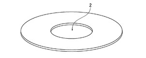
- FIG. 1A and 1B show the appearance of the magnetic disk glass substrate of the embodiment.
- the glass substrate for a magnetic disk in the present embodiment is a donut-shaped thin glass substrate in which an inner hole 2 is formed.
- the size of the glass substrate for magnetic disks is not ask
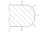
- FIG. 1B is an enlarged view showing a cross section of an end portion on the outer peripheral side of the glass substrate for magnetic disk of the embodiment.
- the magnetic disk glass substrate includes a pair of main surfaces 1p, side wall surfaces 1t arranged along a direction orthogonal to the pair of main surfaces 1p, and a pair of main surfaces 1p and sides.
- chamfered surfaces 1c arranged between the wall surface 1t.
- a side wall surface and a chamfered surface are similarly formed on the inner peripheral side end of the magnetic disk glass substrate.
- the chamfered surface may be formed in an arc shape in a sectional view.
- the glass substrate for a magnetic disk of this embodiment has a shape that satisfies at least the following two requirements 1 and 2 with respect to the surface property of at least one of the side wall surface and the chamfered surface.
- Arithmetic average roughness (Ra) is 0.015 ⁇ m or less
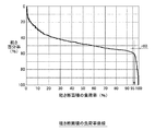
- Requirement 2 In the load factor curve of roughness cross-sectional area, the load factor of roughness cross-sectional area is 95% when the roughness percentage is 60% That's it (see Figure 2)
- FIG. 2 is a diagram showing the requirement 2 in the load factor curve of the roughness cross-sectional area of the side wall surface and / or the chamfered surface.
- “roughness percentage” means that the target surface (or measurement data of the surface shape) is cut when it is assumed that the surface is cut at a certain height in a plane parallel to the surface.
- the height level (cutting level) is a value expressed as a percentage when the maximum height is 0% and the minimum height is 100%.
- “Load factor of roughness cross-sectional area” means the area of the cut surface when the surface is cut at a specific cutting level (ie, when viewed from the direction perpendicular to the cut surface) Is the area of the surface area, not the surface area of the surface).
- “Roughness cross-section load factor curve” represents the relationship between the target surface when the vertical axis is the roughness percentage and the horizontal axis is the roughness cross-section load factor. It is a curve.
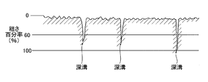
- FIG. 3 is a diagram illustrating a minute region of the cross section of the glass substrate corresponding to the side wall surface and / or the chamfered surface, and the roughness percentage is displayed in the vertical direction of the paper surface.
- a groove concave portion having a roughness percentage exceeding 60% is referred to as a “deep groove”.
- Such deep grooves are extremely small and narrow grooves, but when the main surface is polished with fine particles such as colloidal silica when the glass substrate is produced, the fine particles enter the deep grooves and remain on the side wall surface and / or the chamfered surface. There are things to do.
- the fine particles that have entered the deep groove can move (re-release) to the main surface and cause problems such as head crash failure and thermal asperity failure. Therefore, in order to reduce the number of colloidal silica fine particles remaining on the side wall surface and / or the chamfered surface as much as possible, it is preferable that the number of deep grooves is small in the surface properties of the side wall surface and / or the chamfered surface.
- the load factor of the roughness cross-sectional area when the roughness percentage is 60% is 95% or more.
- the number of deep grooves that is, grooves whose roughness percentage exceeds 60%
- the load factor is less than 5% of the total.
- the load factor curve of the roughness cross-sectional area of FIG. 2 when the value obtained by subtracting the load factor (%) of the roughness cross-sectional area at 100% of the roughness percentage from 100 (%) is r60, the value of r60 is the sidewall surface. It is considered that there is a high correlation with the number of deep grooves formed on the chamfered surface.
- the main surface is polished with fine particles, such as colloidal silica
- the fine particles enter the gap between the outer edge of the glass substrate and the carrier. If deep grooves are formed on the chamfered surface, fine particles such as colloidal silica are easily captured in the deep grooves. Therefore, it is preferable to satisfy the above requirement 2 on the outer peripheral side of the outer peripheral side and inner peripheral side wall surface and / or chamfered surface of the glass substrate. Also, the side wall surface of the outer peripheral side wall surface and the chamfered surface of the glass substrate comes into contact with the inner peripheral surface of the carrier during polishing of the main surface, whereby fine particles such as colloidal silica are exposed to the outer peripheral side wall surface of the glass substrate.
- the fine particles act so as to be embedded in the deep groove on the outer peripheral side wall surface. Therefore, in order to make it difficult for such an action to occur, it is more preferable that the above requirement 2 is satisfied particularly on the side wall surface of the side wall surface and the chamfered surface on the outer peripheral side of the glass substrate.
- the glass substrate for magnetic disks of this embodiment further satisfies the following requirement 3 regarding the surface properties of at least one of the side wall surface and the chamfered surface.
- the load factor curve of the roughness cross-sectional area In the load factor curve of the roughness cross-sectional area, the amount of change in the roughness percentage when the load factor of the roughness cross-sectional area is 20 to 80% is 25% or less (see FIG. 4).
- FIG. 4 is a diagram showing the requirement 3 in the load factor curve of the roughness cross-sectional area of the side wall surface and / or the chamfered surface.
- the reason why it is more preferable to satisfy the requirement 3 is as follows. As long as the above requirement 2 is satisfied, the range where the load factor of the roughness cross-sectional area is 20 to 80% is a region where the deep groove is not included in the surface properties of the glass substrate. By satisfying Requirement 3, in this region, since the groove has a relatively uniform depth, the surface texture is formed more uniformly. Therefore, the possibility that the colloidal silica fine particles enter or adhere to the region other than the deep groove is reduced. can do.
- the arithmetic mean roughness (Ra) and the roughness cross section load factor curve were measured for a predetermined size region on the side wall surface and / or chamfered surface (surface roughness). It is preferable that There may be streak-like grooves (or scratches) on the side wall and / or chamfered surface of the glass substrate for magnetic disks, but the load factor curve of arithmetic mean roughness (Ra) and roughness cross-sectional area This is because, when measured by line roughness, the streak-like groove may not be reflected in the measurement result depending on the measurement direction.
- the magnetic disk glass substrate of the present embodiment preferably has a maximum height (Rz) of 0.15 ⁇ m or less with respect to the surface property of at least one of the side wall surface and the chamfered surface.
- Rz maximum height
- the maximum height (Rz) is 0.15 ⁇ m or less, the depth of the groove generated on the side wall surface or the chamfered surface becomes shallow, so that colloidal silica fine particles are difficult to adhere (residual) to the surface.
- a glass base plate having a predetermined shape that is a base of a glass substrate for a magnetic disk is cut out from the plate glass.
- the glass base plate may be formed by press molding using an upper mold and a lower mold, for example.
- a glass base plate can also be manufactured not only using these methods but using well-known manufacturing methods, such as a downdraw method, a redraw method, and a fusion method.
- Shape processing treatment After the inner hole forming treatment, a shape machining treatment for forming a chamfered surface at the end portions (the outer peripheral end portion and the inner peripheral end portion) is performed.
- a shape machining treatment for forming a chamfered surface at the end portions (the outer peripheral end portion and the inner peripheral end portion) is performed.
- an outer peripheral end and an inner peripheral end of an annular glass substrate are ground using, for example, an electrodeposited diamond grindstone having a particle size of # 400, and a chamfered shape is created at a relatively high speed.
- the chamfered surface is polished to a surface property close to a mirror surface using a grindstone that has a low polishing rate but does not damage the end surface, such as a resin-bonded diamond grindstone having a particle size of # 2000.
- end surface polishing (edge polishing) of an annular glass substrate is performed.
- end face polishing a magnetic slurry lump is formed by holding the magnetic slurry at the lines of magnetic force, and the lump is brought into contact with the inner peripheral end face and the outer peripheral end face of the glass substrate to move relative to each other. Polishing of the end face and outer peripheral end face.
- the side wall surface and the chamfered surface can be polished simultaneously.
- the machining allowance in the end surface polishing process is, for example, about 1 ⁇ m to 5 ⁇ m.
- fine particles such as cerium oxide and zirconium oxide are used as the magnetorheological fluid and abrasive grains.
- Nonpolar oil or polar oil has a viscosity of 1 to 20 (Pa ⁇ sec) in a non-magnetized state at room temperature (20 ° C.), for example.
- polishing the end face it is possible to remove damage such as contamination and scratches on the end face of the glass substrate, preventing the occurrence of thermal asperity failure, and causing corrosion such as sodium and potassium. The occurrence of ion precipitation can be prevented.
- the end surface polishing according to the present embodiment enables extremely precise and high quality processing as compared with the conventional end surface polishing method using a brush. Specifically, the surface roughness and undulation can also be made extremely small, making it difficult to generate deep grooves on the surface.
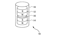
- FIG. 5A to FIG. 5C and FIG. 6 are diagrams for explaining an example of the polishing method in the end face polishing in this embodiment.
- the apparatus 10 for polishing the end face polishes the end face of the glass substrate by using a means for generating magnetism and magnetic slurry.
- the outline of the apparatus 10 for performing end surface polishing will be described.
- the apparatus 10 has a pair of magnets 12 and 14, which are permanent magnets, a spacer 16, and a cylindrical shape made of a nonmagnetic material such as stainless steel.
- a pipe 18. Magnets 12 and 14 and a spacer 16 are built in the pipe 18.
- the glass substrate for end face polishing is held by a holder (not shown).
- the pipe 18 is passed through the inner hole of the glass substrate held by the holder, and a lump 20 of magnetic slurry (see FIG. 5C and FIG. 6) described later is brought into contact with the inner peripheral end face of the glass substrate. Moreover, as shown in FIG. 6, you may arrange
- the outer peripheral end surface of the glass substrate is polished by relatively moving the lump 20 formed by the magnets 12 and 14 in the pipe 18 and the outer peripheral end surface of the glass substrate in contact with each other.
- a holder (not shown) that holds the pipe 18 and the glass substrate of the apparatus 10 is mechanically connected to a drive motor (not shown).
- FIG. 6 shows a case where the inner peripheral end face and the outer peripheral end face of the glass substrate are polished simultaneously, but the present invention is not limited to such a case.
- the polishing of the inner peripheral end face and the outer peripheral end face of the glass substrate may be performed separately.
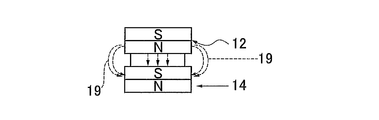
- the magnet 12 and the magnet 14 are close to each other and function as magnetism generating means to form a magnetic force line 19 as shown in FIG. 5B.
- the magnetic force lines 19 proceed so as to protrude outward from the centers of the magnets 12 and 14, and proceed in the thickness direction of the glass substrate.
- a spacer 16 made of a non-magnetic material is provided in order to produce a lump 20 of magnetic slurry on the outer periphery of the pipe 18 as shown in FIG. 5C.
- the magnetic flux density in the magnetism generating means may be set to such an extent that the magnetic slurry lump 20 is formed.
- a permanent magnet is used as the magnetism generating means, but an electromagnet can also be used.
- the magnets 12 and 14 are fixed to the pipe 18 without using the spacer 16, and the separation distance between the end face of the N pole of the magnet 12 and the end face of the S pole of the magnet 14 can be secured constant.
- abrasive grains contained in the magnetic slurry known glass substrate abrasive grains such as cerium oxide, colloidal silica, zirconia oxide, alumina abrasive grains and diamond abrasive grains can be used.
- the particle size of the abrasive grains is, for example, 0.5 to 3 ⁇ m. By using abrasive grains in this range, the inner end face of the glass substrate can be satisfactorily polished.
- the abrasive grains are contained, for example, in an amount of 1 to 20 vol% in the magnetic slurry.
- the glass substrate has an arithmetic average roughness (Ra) of 0.015 ⁇ m or less and a load of roughness cross-sectional area with respect to the surface properties of the side wall surface and / or the chamfered surface.
- the load factor of the roughness cross-sectional area when the roughness percentage is 60% can be 95% or more.
- Precision grinding process In a precision grinding process, it grinds with respect to the main surface of an annular
- the fixed abrasive used in the fine grinding process for example, a grinding pad in which diamond abrasive grains are fixed with a binder such as a resin bond can be used.
- the double-sided grinding apparatus has a pair of upper and lower surface plates (upper surface plate and lower surface plate), and an annular glass substrate mounted on a carrier is sandwiched between the upper surface plate and the lower surface plate. Then, by moving the upper surface plate or the lower surface plate, or both of them, the main surface of the glass substrate can be ground by relatively moving the glass substrate and each surface plate. it can.
- polishing is given to the main surface of the ground glass substrate.
- the purpose of the first polishing is to remove scratches and distortions remaining on the main surface by fine grinding, to adjust waviness, and fine waviness.
- a double-side grinding apparatus having a planetary gear mechanism is used.
- an annular flat plate polishing pad is attached to the upper surface of the lower surface plate and the bottom surface of the upper surface plate, and a glass substrate mounted on a carrier during the operation of the planetary gear mechanism. The polishing pad is pressed against.
- the material of the polishing pad is, for example, urethane foam, and a material impregnated with abrasive grains can be suitably used.
- a polishing liquid containing cerium oxide or zirconium oxide having an average particle diameter of about 0.1 to 5 ⁇ m as polishing abrasive grains is used.
- the average particle size (D50) means a particle size at which the cumulative volume frequency calculated by the volume fraction is 50% calculated from the smaller particle size.
- the surface roughness of the main surface of the glass substrate is polished so that the roughness (Ra) is 0.5 nm or less and the micro waveness (MW-Rq) is 0.5 nm or less.
- the micro waveness can be expressed by an RMS (Rq) value calculated as a roughness of a wavelength band of 100 to 500 ⁇ m on the main surface, and can be measured using, for example, an optical surface shape measuring device.
- the roughness of the main surface is represented by an arithmetic average roughness Ra defined by JIS B0601: 2001, and can be measured by, for example, AFM.
- the arithmetic average roughness Ra when measured at a resolution of 512 ⁇ 512 pixels in a 1 ⁇ m ⁇ 1 ⁇ m square measurement area can be used.
- the glass substrate after the first polishing is chemically strengthened.
- the chemical strengthening liquid for example, a molten liquid of a mixed salt of potassium nitrate and sodium sulfate can be used.
- the chemical strengthening solution lithium ions and sodium ions on the surface layer of the glass substrate are respectively replaced with sodium ions and potassium ions having a relatively large ion radius in the chemical strengthening solution, The glass substrate is strengthened.
- Second Polishing (Final Polishing) Process
- second polishing is performed on the glass substrate that has been chemically strengthened and sufficiently cleaned.
- the second polishing is intended for mirror polishing of the main surface.
- the machining allowance by the second polishing is preferably 5 ⁇ m or less.
- a polishing apparatus similar to that used in the first polishing can be used.
- the difference from the first polishing is that the type and particle size of the free abrasive grains are different and the hardness of the resin polisher is different.
- the resin polisher for example, a suede type soft polisher of foamed polyurethane can be used.
- the Asker C hardness is preferably in the range of 70 to 90.
- the free abrasive grains used for the second polishing for example, fine particles such as colloidal silica made turbid in the slurry are used.
- the average particle diameter (D50) of the colloidal silica abrasive grains is, for example, 50 nm or less, and more preferably 20 nm or less.
- the glass substrate that has undergone the end surface polishing treatment (4) has an arithmetic average roughness (Ra) with respect to the surface properties of the side wall surface and / or the chamfered surface.
- Ra arithmetic average roughness
- the load factor of the roughness cross section when the roughness percentage is 60% is 95% or more. Therefore, even when the average particle size of the colloidal silica used in the second polishing treatment is 20 nm or less, the colloidal silica fine particles enter the grooves (or valleys) on the side wall surface and / or the chamfered surface. Adhering to the side wall surface and / or the chamfered surface can be prevented.
- a magnetic disk is obtained as follows using a magnetic disk glass substrate.
- the magnetic disk is, for example, on the main surface of a glass substrate for magnetic disk (hereinafter simply referred to as “substrate”), in order from the closest to the main surface, at least an adhesion layer, an underlayer, a magnetic layer (magnetic recording layer), and a protection A layer and a lubricating layer are laminated.
- the substrate is introduced into a film forming apparatus that has been evacuated, and a film is sequentially formed from an adhesion layer to a magnetic layer on the main surface of the substrate in an Ar atmosphere by a DC magnetron sputtering method.
- a magnetic recording medium can be formed by forming a protective layer using, for example, C 2 H 4 by a CVD method and subsequently performing nitriding treatment for introducing nitrogen into the surface. Thereafter, for example, PFPE (perfluoropolyether) is applied on the protective layer by a dip coating method, whereby a lubricating layer can be formed.
- the produced magnetic disk is preferably incorporated in an HDD (Hard Disk Drive) as a magnetic recording / reproducing apparatus together with a magnetic head equipped with a DFH (Dynamic Flying Height) control mechanism.
- HDD Hard Disk Drive
- DFH Dynamic Flying Height
- Examples and Comparative Examples In order to confirm the effect of the glass substrate for magnetic disk of the present embodiment, a 2.5-inch magnetic disk is manufactured from the manufactured glass substrate, LUL durability test is performed, and defects such as head crash failure and thermal asperity failure The presence or absence of occurrence was investigated.
- the composition of the glass of the manufactured magnetic disk glass substrate is as follows.
- Glass composition In terms of mass%, SiO 2 is 65.08%, Al 2 O 3 is 15.14%, Li 2 O is 3.61%, Na 2 O is 10.68%, K 2 O is 0.35%, An amorphous aluminosilicate glass having a composition having 0.99% MgO, 2.07% CaO, 1.98% ZrO 2 and 0.10% Fe 2 O 3 , and has a glass transition temperature of 510 ° C. It is.
- the glass substrate for magnetic disks of an Example it produced by performing each process of the said manufacturing method in order.
- a press molding method was used for forming the glass base plate of (1).
- alumina loose abrasive grains were used for forming the glass base plate of (1).
- a chamfered surface was formed on the outer peripheral end portion and the inner peripheral end portion of the glass substrate using an electrodeposited diamond grindstone having a particle size # 400 and a resin bond diamond grindstone having a particle size # 2000 in this order.
- end face polishing of (4) end face polishing with magnetic slurry was performed using the polishing apparatus shown in FIG.
- the polishing slurry used for polishing the end face of the glass substrate was obtained by dispersing cerium oxide abrasive grains in a magnetic fluid in which Fe fine particles were dispersed in nonmagnetic oil.
- the Example of Table 1 was made separately by adjusting suitably the chamfering allowance and the process conditions in the process of (4).
- grinding was performed using a grinding apparatus in which fixed abrasive grains obtained by hardening diamond abrasive grains with resin bonds were attached to a surface plate.
- polishing was performed using a polishing apparatus equipped with a planetary gear mechanism.
- a hard urethane pad was used as a polishing liquid containing cerium oxide abrasive grains and a polishing pad.
- chemical strengthening was performed using a mixed liquid of potassium nitrate and sodium nitrate or the like as the chemical strengthening liquid.
- the second polishing of (8) was performed using a polishing apparatus equipped with a planetary gear mechanism, similarly to the first polishing.
- a polishing pad of soft polisher suede
- Colloidal silica average particle diameter (D50): 30 nm) was used as free abrasive grains.
- the produced magnetic disk glass substrate is a magnetic disk substrate having a nominal 2.5 inch size (inner diameter 20 mm, outer diameter 65 mm, plate thickness 0.635 mm).
- Ra was 0.2 nm or less.
- a chamfered surface was formed using an electrodeposited diamond grindstone having a particle size of # 400.
- grinding using a resin bond diamond grindstone having a particle size of # 2000 was not performed.
- the end face polishing of (4) the end face of the glass substrate was polished with a polishing brush using cerium oxide as free abrasive grains.
- comparative examples were created by appropriately adjusting the chamfering allowance and processing conditions in the processes (3) and (4). Processes other than (3) and (4) were the same as in the example.
- the surface roughness of the chamfered surface and the side wall surface of the glass substrate for magnetic disk of Examples and Comparative Examples was adjusted. .
- the load factor of the roughness cross-sectional area when the roughness percentage was 60% was adjusted by increasing or decreasing the relative speed between the glass substrate and the magnet among the polishing conditions for magnetic polishing.
- the maximum height (Rz) of the chamfered surface and the side wall surface was 0.15 ⁇ m or less.
- the arithmetic average roughness (Ra) of the chamfered surface and the side wall surface of the produced magnetic disk glass substrate, and the load factor of the roughness cross-sectional area when the roughness percentage is 60% are measured with a laser microscope under the following measurement conditions. And obtained from data obtained by measuring the surface shape in an evaluation region of 50 ⁇ m square. [Laser microscope] Resolution: 0.7nm Observation magnification: 1000 times Z-axis measurement pitch: 0.1 ⁇ m Cut-off value ⁇ s: 0.08 ⁇ m Cut-off value ⁇ c: 0.25 mm
- the LUL endurance test is a state in which a hard disk drive (HDD) that constitutes a magnetic disk is placed in a constant temperature and humidity layer at a temperature of 70 ° C. and a humidity of 80%, and the head does not stop moving between the lamp and the ID stopper. It is a test to investigate the occurrence of abnormalities such as dirt and wear of the head after the test.
- HDD hard disk drive
Landscapes
- Engineering & Computer Science (AREA)
- Chemical & Material Sciences (AREA)
- Mechanical Engineering (AREA)
- Ceramic Engineering (AREA)
- Inorganic Chemistry (AREA)
- Manufacturing & Machinery (AREA)
- Manufacturing Of Magnetic Record Carriers (AREA)
- Magnetic Record Carriers (AREA)
- Surface Treatment Of Glass (AREA)
Priority Applications (5)
| Application Number | Priority Date | Filing Date | Title |
|---|---|---|---|
| US14/432,172 US9697860B2 (en) | 2012-09-28 | 2013-06-28 | Magnetic-disk glass substrate, magnetic disk and method for manufacturing magnetic-disk glass substrate |
| JP2014510559A JP5592037B1 (ja) | 2012-09-28 | 2013-06-28 | 磁気ディスク用ガラス基板、磁気ディスク |
| CN201380044680.0A CN104584126B8 (zh) | 2012-09-28 | 2013-06-28 | 磁盘用玻璃基板、磁盘以及磁盘用玻璃基板的制造方法 |
| SG11201501455YA SG11201501455YA (en) | 2012-09-28 | 2013-06-28 | Magnetic-disk glass substrate, magnetic disk and method for manufacturing magnetic-disk glass substrate |
| US15/608,346 US10580448B2 (en) | 2012-09-28 | 2017-05-30 | Magnetic-disk glass substrate, magnetic disk and method for manufacturing magnetic-disk glass substrate |
Applications Claiming Priority (2)
| Application Number | Priority Date | Filing Date | Title |
|---|---|---|---|
| JP2012218412 | 2012-09-28 | ||
| JP2012-218412 | 2012-09-28 |
Related Child Applications (2)
| Application Number | Title | Priority Date | Filing Date |
|---|---|---|---|
| US14/432,172 A-371-Of-International US9697860B2 (en) | 2012-09-28 | 2013-06-28 | Magnetic-disk glass substrate, magnetic disk and method for manufacturing magnetic-disk glass substrate |
| US15/608,346 Continuation US10580448B2 (en) | 2012-09-28 | 2017-05-30 | Magnetic-disk glass substrate, magnetic disk and method for manufacturing magnetic-disk glass substrate |
Publications (1)
| Publication Number | Publication Date |
|---|---|
| WO2014050241A1 true WO2014050241A1 (ja) | 2014-04-03 |
Family
ID=50387658
Family Applications (1)
| Application Number | Title | Priority Date | Filing Date |
|---|---|---|---|
| PCT/JP2013/067940 Ceased WO2014050241A1 (ja) | 2012-09-28 | 2013-06-28 | 磁気ディスク用ガラス基板、磁気ディスク、磁気ディスク用ガラス基板の製造方法 |
Country Status (6)
| Country | Link |
|---|---|
| US (2) | US9697860B2 (enExample) |
| JP (2) | JP5592037B1 (enExample) |
| CN (2) | CN107256712B (enExample) |
| MY (1) | MY169200A (enExample) |
| SG (2) | SG10201706984QA (enExample) |
| WO (1) | WO2014050241A1 (enExample) |
Cited By (3)
| Publication number | Priority date | Publication date | Assignee | Title |
|---|---|---|---|---|
| JP2014084258A (ja) * | 2012-10-25 | 2014-05-12 | Avanstrate Inc | ガラス基板の製造方法 |
| JP6020753B1 (ja) * | 2015-12-28 | 2016-11-02 | 旭硝子株式会社 | 磁気記録媒体用ガラス基板、磁気記録媒体 |
| JP6106813B1 (ja) * | 2015-09-30 | 2017-04-05 | Hoya株式会社 | 磁気ディスク用ガラス基板、磁気ディスク、ガラス基板中間体、及び磁気ディスク用ガラス基板の製造方法 |
Families Citing this family (13)
| Publication number | Priority date | Publication date | Assignee | Title |
|---|---|---|---|---|
| CN107256712B (zh) * | 2012-09-28 | 2020-04-14 | Hoya株式会社 | 磁盘用玻璃基板及其制造方法、磁盘、圆环状的玻璃基板 |
| CN108847256B (zh) * | 2013-02-22 | 2020-04-03 | Hoya株式会社 | 圆环状基板、磁盘用基板及其制造方法、磁盘及其制造方法 |
| US10032472B2 (en) * | 2014-03-31 | 2018-07-24 | Hoya Corporation | Magnetic-disk glass substrate |
| US20170106498A1 (en) * | 2015-10-20 | 2017-04-20 | Hamilton Sundstrand Corporation | Method of manufacturing an actuator assembly component and method of verifying surface finish |
| US10442055B2 (en) * | 2016-02-18 | 2019-10-15 | Iowa State University Research Foundation, Inc. | Lubricated mechanical polishing |
| DE102016107535A1 (de) | 2016-04-22 | 2017-10-26 | Schott Ag | Flachglasprodukt mit erhöhter Kantenfestigkeit und Verfahren zu dessen Herstellung |
| CN110326042B (zh) | 2017-03-31 | 2020-09-11 | Hoya株式会社 | 磁盘用非磁性基板和磁盘 |
| JP6684975B2 (ja) | 2018-02-01 | 2020-04-22 | Hoya株式会社 | ガラススペーサ、ハードディスクドライブ装置、及びガラススペーサの製造方法 |
| JP6616922B1 (ja) | 2018-03-09 | 2019-12-04 | Hoya株式会社 | スペーサ、基板の積層体、基板の製造方法、及び磁気ディスク用基板の製造方法 |
| US11056352B2 (en) | 2018-07-31 | 2021-07-06 | Taiwan Semiconductor Manufacturing Company, Ltd. | Magnetic slurry for highly efficient CMP |
| JP7201808B2 (ja) * | 2019-06-28 | 2023-01-10 | Hoya株式会社 | ガラス板の製造方法および磁気ディスクの製造方法 |
| MY209913A (en) * | 2019-07-31 | 2025-08-12 | Hoya Corp | Method for manufacturing annular glass plate, method for manufacturing glass substrate for magnetic disk, method for manufacturing magnetic disk, annular glass plate, glass substrate for magnetic disk, and magnetic disk |
| CN115307986B (zh) * | 2022-02-22 | 2025-06-06 | 陕西北方动力有限责任公司 | 一种磷化产品含油量的检测方法 |
Citations (5)
| Publication number | Priority date | Publication date | Assignee | Title |
|---|---|---|---|---|
| JPH087264A (ja) * | 1994-06-15 | 1996-01-12 | Fuji Electric Co Ltd | 磁気記録媒体及びその製造方法 |
| JP2000132829A (ja) * | 1998-08-19 | 2000-05-12 | Hoya Corp | 磁気記録媒体用ガラス基板、磁気記録媒体及びそれらの製造方法 |
| JP2001243617A (ja) * | 1999-12-21 | 2001-09-07 | Hoya Corp | 表面粗さに基づく摩擦係数の管理手法、並びに情報記録媒体用基板、情報記録媒体及びその製造方法 |
| JP2007042263A (ja) * | 2005-07-08 | 2007-02-15 | Showa Denko Kk | 磁気記録媒体用基板及び磁気記録媒体並びに磁気記録再生装置 |
| JP2007272995A (ja) * | 2006-03-31 | 2007-10-18 | Hoya Corp | 磁気ディスク装置および非磁性基板の良否判定方法、磁気ディスク、並びに磁気ディスク装置 |
Family Cites Families (32)
| Publication number | Priority date | Publication date | Assignee | Title |
|---|---|---|---|---|
| JPH05114127A (ja) * | 1991-10-23 | 1993-05-07 | Hitachi Ltd | 磁気デイスク及びその製造方法並びに磁気デイスク装置 |
| JPH11221742A (ja) | 1997-09-30 | 1999-08-17 | Hoya Corp | 研磨方法及び研磨装置並びに磁気記録媒体用ガラス基板及び磁気記録媒体 |
| MY124121A (en) * | 1997-11-07 | 2006-06-30 | Hoya Corp | Magnetic recording medium and method of manufacturing the magnetic recording medium |
| SG84541A1 (en) | 1998-08-19 | 2001-11-20 | Hoya Corp | Glass substrate for magnetic recording medium, magnetic recording medium, and method of manufacturing the same |
| US6509111B1 (en) * | 1999-09-24 | 2003-01-21 | Hitachi, Ltd. | Magnetic recording media and magnetic disk apparatus |
| US6706427B2 (en) * | 1999-12-21 | 2004-03-16 | Hoya Corporation | Management technique of friction coefficient based on surface roughness, substrate for information recording medium, information recording medium and manufacture method thereof |
| US6852432B2 (en) * | 2000-06-30 | 2005-02-08 | Hitachi, Ltd. | Magnetic recording media and magnetic disk apparatus |
| US6790509B2 (en) * | 2000-10-19 | 2004-09-14 | Hoya Corporation | Substrate for information recording medium, information recording medium, and method for controlling surface of substrate for information recording medium |
| JP4274708B2 (ja) * | 2001-05-14 | 2009-06-10 | Hoya株式会社 | 磁気記録媒体用ガラス基板及びその製造方法 |
| AU2003292788A1 (en) * | 2002-12-26 | 2004-07-22 | Hoya Corporation | Glass substrate for information recording media and its fabricating method |
| IL157787A (en) * | 2003-09-07 | 2010-12-30 | Mosaid Technologies Inc | Modular outlet for data communications network |
| JP2005078708A (ja) * | 2003-08-29 | 2005-03-24 | Toshiba Corp | 磁気ディスクおよびこれを備えた磁気ディスク装置 |
| US7891212B2 (en) * | 2004-03-25 | 2011-02-22 | Hoya Corporation | Magnetic disk glass substrate |
| CN1993736A (zh) * | 2004-08-11 | 2007-07-04 | 昭和电工株式会社 | 磁记录介质的硅基底及其制造方法以及磁记录介质 |
| JP2006079800A (ja) * | 2004-08-11 | 2006-03-23 | Showa Denko Kk | 磁気記録媒体用シリコン基板及びその製造方法並びに磁気記録媒体 |
| JP2006089363A (ja) * | 2004-08-27 | 2006-04-06 | Showa Denko Kk | 磁気記録媒体用ガラス基板の製造方法、それにより得られる磁気記録媒体用ガラス基板およびこの基板を用いて得られる磁気記録媒体 |
| JP4808985B2 (ja) * | 2005-03-31 | 2011-11-02 | Hoya株式会社 | 磁気ディスク用ガラス基板の製造方法及び磁気ディスクの製造方法 |
| WO2007007650A1 (en) * | 2005-07-08 | 2007-01-18 | Showa Denko K.K. | Substrate for magnetic recording medium, magnetic recording medium, and magnetic recording and reproducing apparatus |
| JP4184384B2 (ja) | 2006-03-16 | 2008-11-19 | Hoya株式会社 | 磁気記録媒体用ガラス基板、及び磁気記録媒体 |
| AU2007285785A1 (en) * | 2006-08-17 | 2008-02-21 | Algepower, Llc | Hydroponic growing enclosure and method for growing, harvesting, processing and distributing algae, related microorganisms and their by products |
| US8241423B2 (en) * | 2006-09-29 | 2012-08-14 | Sumco Techxiv Corporation | Silicon single crystal substrate and manufacture thereof |
| JP2008109125A (ja) * | 2006-09-29 | 2008-05-08 | Sumco Techxiv株式会社 | シリコン単結晶基板及びその製造方法 |
| JP5029952B2 (ja) * | 2007-09-06 | 2012-09-19 | 富士電機株式会社 | ガラス基板およびその製造方法、ならびに当該ガラス基板を用いた磁気ディスク |
| JP2009093744A (ja) | 2007-10-05 | 2009-04-30 | Hoya Corp | 磁気記録媒体用ガラス基板の製造方法及び磁気記録媒体 |
| JP2009289370A (ja) * | 2008-05-30 | 2009-12-10 | Furukawa Electric Co Ltd:The | 磁気ディスク用ガラス基板 |
| MY153605A (en) * | 2008-06-30 | 2015-02-27 | Hoya Corp | Substrate for magnetic disk and magnetic disk |
| SG194382A1 (en) | 2008-09-30 | 2013-11-29 | Hoya Corp | Glass substrate for a magnetic disk and magnetic disk |
| MY165019A (en) | 2011-03-31 | 2018-02-28 | Hoya Corp | Method of manufacturing a glass substrate for a magnetic disk and method of manufacturing a magnetic disk |
| KR101477469B1 (ko) * | 2012-03-30 | 2014-12-29 | 호야 가부시키가이샤 | 마스크 블랭크용 기판, 다층 반사막 부착 기판, 투과형 마스크 블랭크, 반사형 마스크 블랭크, 투과형 마스크, 반사형 마스크 및 반도체 장치의 제조 방법 |
| CN107256712B (zh) * | 2012-09-28 | 2020-04-14 | Hoya株式会社 | 磁盘用玻璃基板及其制造方法、磁盘、圆环状的玻璃基板 |
| US10032472B2 (en) * | 2014-03-31 | 2018-07-24 | Hoya Corporation | Magnetic-disk glass substrate |
| CN110503983B (zh) * | 2015-09-30 | 2021-03-19 | Hoya株式会社 | 磁盘用玻璃基板及其制造方法、磁盘和玻璃基板中间体 |
-
2013
- 2013-06-28 CN CN201710451295.8A patent/CN107256712B/zh active Active
- 2013-06-28 WO PCT/JP2013/067940 patent/WO2014050241A1/ja not_active Ceased
- 2013-06-28 US US14/432,172 patent/US9697860B2/en active Active
- 2013-06-28 SG SG10201706984QA patent/SG10201706984QA/en unknown
- 2013-06-28 CN CN201380044680.0A patent/CN104584126B8/zh active Active
- 2013-06-28 MY MYPI2015700585A patent/MY169200A/en unknown
- 2013-06-28 JP JP2014510559A patent/JP5592037B1/ja active Active
- 2013-06-28 SG SG11201501455YA patent/SG11201501455YA/en unknown
-
2014
- 2014-05-13 JP JP2014099966A patent/JP6215770B2/ja active Active
-
2017
- 2017-05-30 US US15/608,346 patent/US10580448B2/en active Active
Patent Citations (5)
| Publication number | Priority date | Publication date | Assignee | Title |
|---|---|---|---|---|
| JPH087264A (ja) * | 1994-06-15 | 1996-01-12 | Fuji Electric Co Ltd | 磁気記録媒体及びその製造方法 |
| JP2000132829A (ja) * | 1998-08-19 | 2000-05-12 | Hoya Corp | 磁気記録媒体用ガラス基板、磁気記録媒体及びそれらの製造方法 |
| JP2001243617A (ja) * | 1999-12-21 | 2001-09-07 | Hoya Corp | 表面粗さに基づく摩擦係数の管理手法、並びに情報記録媒体用基板、情報記録媒体及びその製造方法 |
| JP2007042263A (ja) * | 2005-07-08 | 2007-02-15 | Showa Denko Kk | 磁気記録媒体用基板及び磁気記録媒体並びに磁気記録再生装置 |
| JP2007272995A (ja) * | 2006-03-31 | 2007-10-18 | Hoya Corp | 磁気ディスク装置および非磁性基板の良否判定方法、磁気ディスク、並びに磁気ディスク装置 |
Cited By (9)
| Publication number | Priority date | Publication date | Assignee | Title |
|---|---|---|---|---|
| JP2014084258A (ja) * | 2012-10-25 | 2014-05-12 | Avanstrate Inc | ガラス基板の製造方法 |
| JP6106813B1 (ja) * | 2015-09-30 | 2017-04-05 | Hoya株式会社 | 磁気ディスク用ガラス基板、磁気ディスク、ガラス基板中間体、及び磁気ディスク用ガラス基板の製造方法 |
| WO2017057686A1 (ja) * | 2015-09-30 | 2017-04-06 | Hoya株式会社 | 磁気ディスク用ガラス基板、磁気ディスク、ガラス基板中間体、及び磁気ディスク用ガラス基板の製造方法 |
| JP2017130249A (ja) * | 2015-09-30 | 2017-07-27 | Hoya株式会社 | 磁気ディスク用ガラス基板、磁気ディスク、ガラス基板中間体、及び磁気ディスク用ガラス基板の製造方法 |
| US10720180B2 (en) | 2015-09-30 | 2020-07-21 | Hoya Corporation | Magnetic-disk glass substrate, magnetic-disk glass substrate intermediate, and method for manufacturing magnetic-disk glass substrate |
| US11211090B2 (en) | 2015-09-30 | 2021-12-28 | Hoya Corporation | Magnetic-disk glass substrate, magnetic-disk glass substrate intermediate, and method for manufacturing magnetic-disk glass substrate |
| US11710505B2 (en) | 2015-09-30 | 2023-07-25 | Hoya Corporation | Magnetic-disk glass substrate, magnetic-disk glass substrate intermediate, and method for manufacturing magnetic-disk glass substrate |
| JP6020753B1 (ja) * | 2015-12-28 | 2016-11-02 | 旭硝子株式会社 | 磁気記録媒体用ガラス基板、磁気記録媒体 |
| WO2017115473A1 (ja) * | 2015-12-28 | 2017-07-06 | 旭硝子株式会社 | 磁気記録媒体用ガラス基板及び磁気記録媒体 |
Also Published As
| Publication number | Publication date |
|---|---|
| US20170263278A1 (en) | 2017-09-14 |
| MY169200A (en) | 2019-02-26 |
| CN107256712A (zh) | 2017-10-17 |
| CN104584126A (zh) | 2015-04-29 |
| CN107256712B (zh) | 2020-04-14 |
| US9697860B2 (en) | 2017-07-04 |
| US10580448B2 (en) | 2020-03-03 |
| JP5592037B1 (ja) | 2014-09-17 |
| US20150255103A1 (en) | 2015-09-10 |
| SG10201706984QA (en) | 2017-10-30 |
| CN104584126B (zh) | 2017-06-23 |
| JPWO2014050241A1 (ja) | 2016-08-22 |
| CN104584126B8 (zh) | 2017-08-08 |
| JP2014179160A (ja) | 2014-09-25 |
| SG11201501455YA (en) | 2015-05-28 |
| JP6215770B2 (ja) | 2017-10-18 |
Similar Documents
| Publication | Publication Date | Title |
|---|---|---|
| JP5592037B1 (ja) | 磁気ディスク用ガラス基板、磁気ディスク | |
| JP5860195B1 (ja) | 磁気ディスク用ガラス基板 | |
| JP2016076290A (ja) | 磁気ディスク用ガラス基板および磁気ディスク | |
| JP6577501B2 (ja) | 磁気ディスク用ガラス基板、磁気ディスク、ガラス基板中間体、及び磁気ディスク用ガラス基板の製造方法 | |
| JP5574392B1 (ja) | 磁気ディスク用ガラス基板、磁気ディスク | |
| JPWO2008004471A1 (ja) | ガラス基板の製造方法、磁気ディスクおよびその製造方法 | |
| CN104011795B (zh) | 磁盘用玻璃基板的制造方法 | |
| JP5870187B2 (ja) | 磁気ディスク用ガラス基板、磁気ディスク、磁気ディスクドライブ装置 | |
| CN104813396A (zh) | 磁盘用玻璃基板的制造方法以及磁盘的制造方法 |
Legal Events
| Date | Code | Title | Description |
|---|---|---|---|
| ENP | Entry into the national phase |
Ref document number: 2014510559 Country of ref document: JP Kind code of ref document: A |
|
| 121 | Ep: the epo has been informed by wipo that ep was designated in this application |
Ref document number: 13842761 Country of ref document: EP Kind code of ref document: A1 |
|
| WWE | Wipo information: entry into national phase |
Ref document number: 14432172 Country of ref document: US |
|
| NENP | Non-entry into the national phase |
Ref country code: DE |
|
| 122 | Ep: pct application non-entry in european phase |
Ref document number: 13842761 Country of ref document: EP Kind code of ref document: A1 |