WO2014049933A1 - 密閉型電池の製造方法、及び検査装置 - Google Patents
密閉型電池の製造方法、及び検査装置 Download PDFInfo
- Publication number
- WO2014049933A1 WO2014049933A1 PCT/JP2013/004780 JP2013004780W WO2014049933A1 WO 2014049933 A1 WO2014049933 A1 WO 2014049933A1 JP 2013004780 W JP2013004780 W JP 2013004780W WO 2014049933 A1 WO2014049933 A1 WO 2014049933A1
- Authority
- WO
- WIPO (PCT)
- Prior art keywords
- sealed battery
- battery
- voltage
- sealed
- case
- Prior art date
- Legal status (The legal status is an assumption and is not a legal conclusion. Google has not performed a legal analysis and makes no representation as to the accuracy of the status listed.)
- Ceased
Links
Images
Classifications
-
- G—PHYSICS
- G01—MEASURING; TESTING
- G01R—MEASURING ELECTRIC VARIABLES; MEASURING MAGNETIC VARIABLES
- G01R31/00—Arrangements for testing electric properties; Arrangements for locating electric faults; Arrangements for electrical testing characterised by what is being tested not provided for elsewhere
- G01R31/36—Arrangements for testing, measuring or monitoring the electrical condition of accumulators or electric batteries, e.g. capacity or state of charge [SoC]
- G01R31/385—Arrangements for measuring battery or accumulator variables
- G01R31/3865—Arrangements for measuring battery or accumulator variables related to manufacture, e.g. testing after manufacture
-
- H—ELECTRICITY
- H01—ELECTRIC ELEMENTS
- H01M—PROCESSES OR MEANS, e.g. BATTERIES, FOR THE DIRECT CONVERSION OF CHEMICAL ENERGY INTO ELECTRICAL ENERGY
- H01M10/00—Secondary cells; Manufacture thereof
- H01M10/05—Accumulators with non-aqueous electrolyte
- H01M10/058—Construction or manufacture
-
- G—PHYSICS
- G01—MEASURING; TESTING
- G01R—MEASURING ELECTRIC VARIABLES; MEASURING MAGNETIC VARIABLES
- G01R31/00—Arrangements for testing electric properties; Arrangements for locating electric faults; Arrangements for electrical testing characterised by what is being tested not provided for elsewhere
- G01R31/36—Arrangements for testing, measuring or monitoring the electrical condition of accumulators or electric batteries, e.g. capacity or state of charge [SoC]
- G01R31/382—Arrangements for monitoring battery or accumulator variables, e.g. SoC
- G01R31/3835—Arrangements for monitoring battery or accumulator variables, e.g. SoC involving only voltage measurements
-
- H—ELECTRICITY
- H01—ELECTRIC ELEMENTS
- H01M—PROCESSES OR MEANS, e.g. BATTERIES, FOR THE DIRECT CONVERSION OF CHEMICAL ENERGY INTO ELECTRICAL ENERGY
- H01M10/00—Secondary cells; Manufacture thereof
- H01M10/34—Gastight accumulators
-
- H—ELECTRICITY
- H01—ELECTRIC ELEMENTS
- H01M—PROCESSES OR MEANS, e.g. BATTERIES, FOR THE DIRECT CONVERSION OF CHEMICAL ENERGY INTO ELECTRICAL ENERGY
- H01M10/00—Secondary cells; Manufacture thereof
- H01M10/42—Methods or arrangements for servicing or maintenance of secondary cells or secondary half-cells
- H01M10/44—Methods for charging or discharging
- H01M10/446—Initial charging measures
-
- H—ELECTRICITY
- H01—ELECTRIC ELEMENTS
- H01M—PROCESSES OR MEANS, e.g. BATTERIES, FOR THE DIRECT CONVERSION OF CHEMICAL ENERGY INTO ELECTRICAL ENERGY
- H01M10/00—Secondary cells; Manufacture thereof
- H01M10/42—Methods or arrangements for servicing or maintenance of secondary cells or secondary half-cells
- H01M10/48—Accumulators combined with arrangements for measuring, testing or indicating the condition of cells, e.g. the level or density of the electrolyte
-
- Y—GENERAL TAGGING OF NEW TECHNOLOGICAL DEVELOPMENTS; GENERAL TAGGING OF CROSS-SECTIONAL TECHNOLOGIES SPANNING OVER SEVERAL SECTIONS OF THE IPC; TECHNICAL SUBJECTS COVERED BY FORMER USPC CROSS-REFERENCE ART COLLECTIONS [XRACs] AND DIGESTS
- Y02—TECHNOLOGIES OR APPLICATIONS FOR MITIGATION OR ADAPTATION AGAINST CLIMATE CHANGE
- Y02E—REDUCTION OF GREENHOUSE GAS [GHG] EMISSIONS, RELATED TO ENERGY GENERATION, TRANSMISSION OR DISTRIBUTION
- Y02E60/00—Enabling technologies; Technologies with a potential or indirect contribution to GHG emissions mitigation
- Y02E60/10—Energy storage using batteries
-
- Y—GENERAL TAGGING OF NEW TECHNOLOGICAL DEVELOPMENTS; GENERAL TAGGING OF CROSS-SECTIONAL TECHNOLOGIES SPANNING OVER SEVERAL SECTIONS OF THE IPC; TECHNICAL SUBJECTS COVERED BY FORMER USPC CROSS-REFERENCE ART COLLECTIONS [XRACs] AND DIGESTS
- Y02—TECHNOLOGIES OR APPLICATIONS FOR MITIGATION OR ADAPTATION AGAINST CLIMATE CHANGE
- Y02P—CLIMATE CHANGE MITIGATION TECHNOLOGIES IN THE PRODUCTION OR PROCESSING OF GOODS
- Y02P70/00—Climate change mitigation technologies in the production process for final industrial or consumer products
- Y02P70/50—Manufacturing or production processes characterised by the final manufactured product
Definitions
- the present invention relates to a method for manufacturing a sealed battery and an inspection device that can accurately determine whether or not the battery case of the sealed battery is damaged.
- Patent Document 1 requires a special measuring device and the like, which can be a factor that complicates the manufacturing process.
- the present invention has been made to solve such problems, and provides a sealed battery manufacturing method and an inspection apparatus capable of determining damage in a battery case of the sealed battery with high accuracy by a simple method.
- the main purpose is to do.
- One aspect of the present invention for achieving the above object is that the voltage of the sealed battery when a charging current of a predetermined value or more is supplied to the sealed battery for a predetermined time after the initial charge of the sealed battery. And a step of determining the presence or absence of damage in the battery case of the sealed battery based on the change in the measured voltage. .
- the presence or absence of a dent in the battery case of the sealed battery may be determined based on the change in the measured voltage.
- the slope of the voltage increases in the time variation of the measured voltage, it may be determined that the battery case of the sealed battery has a dent.
- the voltage of the sealed battery may be measured when a charging current of 20 to 25 C is applied to the sealed battery for 0.5 to 1.0 seconds after the initial charging.
- the voltage of the sealed battery when a charging current of 20 C is applied to the sealed battery for 0.5 seconds may be measured.
- the sealed battery may be a square lithium ion battery.
- one mode of the present invention for achieving the above object is to measure the voltage of the sealed battery when a charging current of a predetermined value or more flows for a predetermined time with respect to the sealed battery after initial charging.
- An inspection apparatus comprising: a measurement unit; and a determination unit that determines whether or not the battery case of the sealed battery is damaged based on a change in voltage measured by the measurement unit. Good.
- an output unit that outputs at least one of a change in the voltage of the sealed battery measured by the measurement unit and a determination result determined by the determination unit may be further provided.
- the present invention it is possible to provide a sealed battery manufacturing method and an inspection apparatus that can determine damage in a battery case of a sealed battery with high accuracy by a simple technique.
- FIG. 1 is a block diagram showing a schematic system configuration of an inspection apparatus according to an embodiment of the present invention. It is a flowchart which shows the test
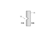
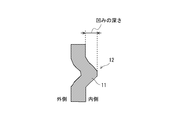
- a metal battery case in which the battery element is stored is inspected for damage. Further, among the damages of the battery case 11, it is particularly important to discriminate between a simple scratch 13 (FIG. 7A) that does not involve deformation of the battery case 11 and a dent 12 (FIG. 7B) that accompanies deformation of the battery case 11. It becomes. This is because when the dent 12 is generated in the battery case 11, the dent 12 itself greatly affects the battery performance, unlike the mere scratch 13.
- the internal behavior of the battery is locally changed, which may be a factor of deteriorating the battery performance. This is caused by a local change in which a part of the recess 12 of the battery case 11 approaches the electrode, and only the close part has improved lithium deposition resistance, and conversely, the other peripheral part has deteriorated lithium deposition resistance. It is.
- the dent 12 of the battery case 11 is distinguished from the mere scratch 13 with high accuracy in the manufacturing process of the sealed battery.
- the quality of the case 11 can be determined with high accuracy.
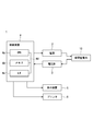
- FIG. 1 is a block diagram showing a schematic system configuration of an inspection apparatus according to an embodiment of the present invention.
- the inspection device 1 includes a power source 2 that supplies current to the sealed battery 10, a voltmeter 3 that measures the voltage of the sealed battery 10, and a determination device 4 that determines whether the sealed battery 10 is good or bad. And a display device 5 and a printer 6 for outputting determination results and the like.
- the power source 2 is connected to the sealed battery 10 and the determination device 4 and supplies a predetermined charging current to the sealed battery 10 in accordance with a control signal from the determination device 4.
- the voltmeter 3 is a specific example of measuring means, and is connected to the sealed battery 10 and the determination device 4.
- the voltmeter 3 measures the voltage value of the sealed battery 10 and outputs the measured voltage value to the determination device 4.
- the determination device 4 is a specific example of the determination means, and the dent 12 of the battery case 11 is distinguished from the mere scratch 13 with high accuracy based on the change in the voltage of the sealed battery 10 measured by the voltmeter 3. . And the determination apparatus 4 can determine the quality of the battery case 11 of the sealed battery 10 based on the determination result of the dent 12.
- the determination device 4 when the voltage gradient of the sealed battery 10 increases in the time change of the voltage of the sealed battery 10 measured by the voltmeter 3, the determination device 4 has a dent 12 in the battery case 11 of the sealed battery 10.
- the battery case 11 of the sealed battery 10 is determined as a defective product. More specifically, the determination device 4 determines the second measurement time in which the slope of the voltage in the first measurement time is continuous with the first measurement time in the time change of the voltage of the sealed battery 10 measured by the voltmeter 3. Is larger than the slope of the voltage, it is determined that the battery case 11 of the sealed battery 10 has a recess 12, and the battery case 11 of the sealed battery 10 is determined to be defective.
- the determination device 4 includes, for example, a CPU (Central Processing Unit) 4a that performs arithmetic processing, control processing, and the like, a ROM (Read Memory Only) or a RAM (Random) that stores a calculation program executed by the CPU 4a, a control program, and the like.
- the hardware is mainly composed of a microcomputer composed of a memory 4b composed of (Access Memory), an interface unit (I / F) 4c for inputting / outputting signals to / from the outside, and the like.
- the CPU 4a, the memory 4b, and the interface unit 4c are connected to each other via a data bus 4d.
- the display device 5 and the printer 6 are specific examples of output means.
- the presence / absence determination result and the non-defective product determination result are output to the user.
- the display device 5 includes, for example, a liquid crystal display device, an organic EL display device, and the like.
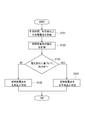
- FIG. 2 is a flowchart showing an inspection flow of the inspection apparatus in the manufacturing method of the sealed battery.
- the determination device 4 causes the power source 2 to supply the sealed battery 10 with a charging current at a high rate of a predetermined time (for a low number of seconds) and a predetermined value or more (step) S101).
- the determination device 4 may supply the charging current from the power source 2 to the sealed battery 10 for a predetermined time and at a high rate equal to or higher than a predetermined value before the aging process and after the initial charging. If there is, the charging current may be supplied in an arbitrary step.
- the voltmeter 3 measures the voltage of the sealed battery 10 and outputs the measured voltage value of the sealed battery 10 to the determination device 4 (step S102).
- the determination device 4 determines the presence / absence of the dent 12 in the battery case 11 of the sealed battery 10 based on the change in the voltage of the sealed battery 10 measured by the voltmeter 3 (step S103). Based on this, the quality of the battery case 11 of the sealed battery 10 is determined.
- the sealed device When the determination device 4 determines that there is a recess 12 in the battery case 11 of the sealed battery 10 based on the change in the voltage of the sealed battery 10 measured by the voltmeter 3 (YES in step S103), the sealed device.
- the battery case 11 of the battery 10 is determined as a defective product (step S104).
- the determination device 4 determines that there is no dent 12 in the battery case 11 of the sealed battery 10 based on the change in the voltage of the sealed battery 10 measured by the voltmeter 3 (NO in step S103).
- the battery case 11 of the sealed battery 10 is determined to be a good product (step S105).
- the determination device 4 determines the presence / absence of the dent 12 in the battery case 11 of the sealed battery 10 based on the voltage change of the sealed battery 10 measured by the voltmeter 3 will be described in detail.
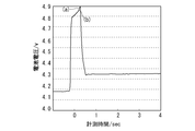
- FIG. 3 is a diagram showing a result of comparison between the case where the battery case has a dent and the case where there is no dent, with respect to a change in the voltage of the sealed battery.
- the charging current 20 ⁇ / b> C is allowed to flow through the sealed battery 10 for 0.5 seconds, and the change in the voltage of the sealed battery 10 is measured.
- the sealed battery 10 is a rectangular battery having a substantially rectangular parallelepiped shape, for example.
- the sealed type battery 10 has a sealed type as compared to the case (b) where the battery case 11 of the sealed battery 10 does not have a dent 12. It can be seen that the voltage gradient of the battery 10 is increasing. For example, the voltage gradient of the sealed battery 10 in the second measurement time 0.3 to 0.5 seconds is larger than the voltage gradient of the sealed battery 10 in the first measurement time 0.0 to 0.3 seconds. It has become.
- the determination device 4 is recessed in the battery case 11 of the sealed battery 10 when the voltage gradient of the sealed battery 10 increases in the time change of the voltage of the sealed battery 10 measured by the voltmeter 3. 12 is determined to be present.
- the voltmeter 3 measures the voltage of the sealed battery 10 when a charging current of 20 C is supplied to the sealed battery 10 for 0.5 seconds. Then, the determination device 4 has a second change in the time variation of the voltage of the sealed battery 10 measured by the voltmeter 3 than the slope of the voltage of the sealed battery 10 in the first measurement time 0.0 to 0.3 seconds. When the slope of the voltage of the sealed battery 10 with a measurement time of 0.3 to 0.5 seconds increases, it is determined that the battery case 11 of the sealed battery 10 has a dent 12.
- the determination device 4 outputs a graph or the like showing the relationship between the time and the voltage of the sealed battery 10 as shown in FIG. 3 to the display device (liquid crystal display device, organic EL display device, etc.) 5 or the printer 6. May be. Then, the user may determine the presence or absence of the recess 12 in the battery case 11 of the sealed battery 10 from the relationship between the time output to the display device 5 or the printer 6 and the change in the voltage of the sealed battery 10.
- step S101 the charging current value supplied from the power source 2 to the sealed battery 10 in the above (step S101) and the setting method of the supply time will be described.
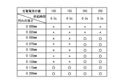
- FIG. 4 is a diagram showing the relationship between the charging current supplied to the sealed battery, the supply time (0.5 seconds), and the depth of the dent of the battery case that can be detected.
- ⁇ indicates a case where the dent 12 can be detected in the battery case 11 of the sealed battery 10, and ⁇ indicates that the dent 12 is detected on the battery case 11 of the sealed battery 10. Indicates a case where it cannot be done.
- the depth of the dent 12 is, for example, a distance from the inner surface of the battery case 11 of the sealed battery 10 to the tip of the dent 12 that protrudes most inward as shown in FIG. 7B.
- the recess 12 having a depth of 0.050 mm or more that has a relatively large effect on the battery performance is formed in the battery of the sealed battery 10. It can be seen that it can be detected on the case 11.
- the charging current for the sealed battery 10 is set to 20 to 25C.
- it is most preferably set to 20C.
- the set charging current values 20C and 25C are not strictly limited to the set values, and have a certain range within the range or the error range in which the same effects can be obtained. You may do it.
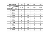
- FIG. 5 is a diagram showing the relationship between the charging current (20C) supplied to the sealed battery, the supply time thereof, and the depth of the recess 12 of the battery case 11 of the sealed battery 10 that can be detected.
- the recess 12 As shown in FIG. 5, when the charging current supply time for the sealed battery 10 is 0.5 to 1.0 seconds, the recess 12 having a depth of 0.05 mm or more that has a relatively large effect on the battery performance is provided. It can be seen that detection is possible on 10 battery cases 11.
- the charging current supply time for the sealed battery 10 is set to 2.0 seconds, the current distribution is generated, so that the detection accuracy of the dent 12 is lowered, and the depth of the dent 12 that can be detected is 0.075 mm or more.
- the charging current supply time for the sealed battery 10 is set to 0.5 to 1. It is preferably set to 0 seconds, and most preferably 0.5 seconds. Note that the charging current supply times of 0.5 seconds and 1.0 seconds (critical values) that are set are not strictly limited to the values that are set, but ranges or errors that exhibit the same operational effects. The range may have some width.
- the time variation of the voltage of the sealed battery 10 when a charging current of 20 to 25 C is supplied to the sealed battery 10 at a supply time of 0.5 to 1.0 seconds It is understood that it is preferable to determine the presence or absence of the recess 12 in the battery case 11 of the sealed battery 10 from the slope of the voltage. Furthermore, the time change of the voltage of the sealed battery 10 when a charging current of 20 C is supplied to the sealed battery 10 at a supply time of 0.5 seconds is measured, and the battery case of the sealed battery 10 is determined from the slope of the voltage. It can be seen that it is most preferable to determine the presence or absence of the recess 12 in 11.
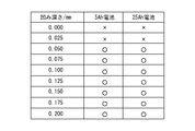
- FIG. 6 is a diagram showing the result of determining whether there is a dent in the battery case in a sealed battery with a capacity of 5 Ah and a sealed battery with a capacity of 25 Ah.
- FIG. 6 it is determined whether or not there is a dent 12 in the battery case 11 of the sealed battery 10 when a charging current of 20 C is supplied to the sealed battery 10 of each capacity for a supply time of 0.5 seconds. Yes.
- the voltage of sealed battery 10 when a charging current of a predetermined value or more is applied to sealed battery 10 for a predetermined time. Measurement is performed, and it is determined that the battery case 11 of the sealed battery 10 has the dent 12 when the slope of the voltage increases in the time variation of the measured voltage. Thereby, in the manufacturing process of the sealed battery 10, the dent 12 of the battery case 11 is distinguished from the mere scratches 13 with high accuracy, so that the quality of the battery case 11 can be determined with high accuracy. .
- a lithium ion secondary battery is applied as the sealed battery 10, but not limited to this, a nickel hydride storage battery, a lead storage battery, a lithium ion polymer secondary battery, a nickel cadmium storage battery, nickel An iron storage battery, a nickel zinc storage battery, a silver zinc oxide storage battery, etc. may be applied and it is applicable to arbitrary sealed batteries. Further, the present invention is not limited to this, and is applicable to a sealed battery having an arbitrary shape such as a circular battery.
- the processing shown in FIG. 2 can be realized by causing the CPU 4a to execute a computer program.
- the computer program can be provided by being recorded on a recording medium, or can be provided by being transmitted via the Internet or another communication medium.
- the storage medium includes, for example, a flexible disk, a hard disk, a magnetic disk, a magneto-optical disk, a CD-ROM, a DVD, a ROM cartridge, a RAM memory cartridge with battery backup, a flash memory cartridge, a nonvolatile RAM cartridge, and the like.
- the communication medium includes a wired communication medium such as a telephone line, a wireless communication medium such as a microwave line, and the like.
Landscapes
- Engineering & Computer Science (AREA)
- Manufacturing & Machinery (AREA)
- Chemical & Material Sciences (AREA)
- Chemical Kinetics & Catalysis (AREA)
- Electrochemistry (AREA)
- General Chemical & Material Sciences (AREA)
- Physics & Mathematics (AREA)
- General Physics & Mathematics (AREA)
- Secondary Cells (AREA)
- Sealing Battery Cases Or Jackets (AREA)
Abstract
Description
この一態様において、前記計測された電圧の変化に基づいて、前記密閉型電池の電池ケースおける凹みの有無を判定してもよい。
この一態様において、前記計測された電圧の時間変化において、前記電圧の傾きが増加したとき、前記密閉型電池の電池ケースに凹みが有ると判定してもよい。
この一態様において、前記計測された電圧の時間変化において、第1計測時間における電圧の傾きが該第1計測時間に連続する第2計測時間における電圧の傾きよりも大きいとき、前記密閉型電池の電池ケースに凹みが有ると判定してもよい。
この一態様において、前記初期充電後に、前記密閉型電池に対して0.5~1.0秒間かつ20~25Cの充電電流を流したときの前記密閉型電池の電圧を計測してもよい。
この一態様において、前記初期充電後に、前記密閉型電池に対して0.5秒間かつ20Cの充電電流を流したときの前記密閉型電池の電圧を計測してもよい。
この一態様において、前記計測された電圧の時間変化において、計測時間0.0~0.3秒間の電圧の傾きより計測時間0.3~0.5秒間の電圧の傾きが大きくなるとき、前記密閉型電池の電池ケースに凹みが有ると判定してもよい。
この一態様において、前記密閉型電池は、角型形状のリチウムイオン電池であってもよい。
他方、上記目的を達成するための本発明の一態様は、初期充電後の密閉型電池に対して所定時間、かつ所定値以上の充電電流を流したときの前記密閉型電池の電圧を計測する計測手段と、前記計測手段により計測された電圧の変化に基づいて、前記密閉型電池の電池ケースおける損傷の有無を判定する判定手段と、を備える、ことを特徴とする検査装置であってもよい。
この一態様において、前記計測手段により計測された前記密閉型電池の電圧の変化、及び前記判定手段により判定された判定結果、のうち少なくとも一方を出力する出力手段を更に備えていてもよい。
2 電源
3 電圧計
4 判定装置
5 表示装置
6 プリンタ
10 密閉型電池
11 電池ケース
12 凹み
13 傷
Claims (10)
- 密閉型電池の初期充電後に、前記密閉型電池に対して所定時間、かつ所定値以上の充電電流を流したときの前記密閉型電池の電圧を計測するステップと、
前記計測された電圧の変化に基づいて、前記密閉型電池の電池ケースおける損傷の有無を判定するステップと、
を含む、ことを特徴とする密閉型電池の製造方法。 - 請求項1記載の密閉型電池の製造方法であって、
前記計測された電圧の変化に基づいて、前記密閉型電池の電池ケースおける凹みの有無を判定する、ことを特徴とする密閉型電池の製造方法。 - 請求項2記載の密閉型電池の製造方法であって、
前記計測された電圧の時間変化において、前記電圧の傾きが増加したとき、前記密閉型電池の電池ケースに凹みが有ると判定する、ことを特徴とする密閉型電池の製造方法。 - 請求項3記載の密閉型電池の製造方法であって、
前記計測された電圧の時間変化において、第1計測時間における電圧の傾きが該第1計測時間に連続する第2計測時間における電圧の傾きよりも大きいとき、前記密閉型電池の電池ケースに凹みが有ると判定する、ことを特徴とする密閉型電池の製造方法。 - 請求項1乃至4のうちいずれか1項記載の密閉型電池の製造方法であって、
前記初期充電後に、前記密閉型電池に対して0.5~1.0秒間かつ20~25Cの充電電流を流したときの前記密閉型電池の電圧を計測する、ことを特徴とする密閉型電池の製造方法。 - 請求項1乃至5のうちいずれか1項記載の密閉型電池の製造方法であって、
前記初期充電後に、前記密閉型電池に対して0.5秒間かつ20Cの充電電流を流したときの前記密閉型電池の電圧を計測する、ことを特徴とする密閉型電池の製造方法。 - 請求項6記載の密閉型電池の製造方法であって、
前記計測された電圧の時間変化において、計測時間0.0~0.3秒間の電圧の傾きより計測時間0.3~0.5秒間の電圧の傾きが大きくなるとき、前記密閉型電池の電池ケースに凹みが有ると判定する、ことを特徴とする密閉型電池の製造方法。 - 請求項1乃至7のうちいずれか1項記載の密閉型電池の製造方法であって、
前記密閉型電池は、角型形状のリチウムイオン電池である、ことを特徴とする密閉型電池の製造方法。 - 初期充電後の密閉型電池に対して所定時間、かつ所定値以上の充電電流を流したときの前記密閉型電池の電圧を計測する計測手段と、
前記計測手段により計測された電圧の変化に基づいて、前記密閉型電池の電池ケースおける損傷の有無を判定する判定手段と、
を備える、ことを特徴とする検査装置。 - 請求項9記載の検査装置であって、
前記計測手段により計測された前記密閉型電池の電圧の変化、及び前記判定手段により判定された判定結果、のうち少なくとも一方を出力する出力手段を更に備える、ことを特徴とする検査装置。
Priority Applications (2)
| Application Number | Priority Date | Filing Date | Title |
|---|---|---|---|
| CN201380049165.1A CN104662731B (zh) | 2012-09-26 | 2013-08-07 | 密封型电池的制造方法以及检查装置 |
| US14/429,810 US9372239B2 (en) | 2012-09-26 | 2013-08-07 | Sealed battery manufacturing method and inspection device |
Applications Claiming Priority (2)
| Application Number | Priority Date | Filing Date | Title |
|---|---|---|---|
| JP2012-212596 | 2012-09-26 | ||
| JP2012212596A JP5724980B2 (ja) | 2012-09-26 | 2012-09-26 | 密閉型電池の製造方法、検査装置、及び検査プログラム |
Publications (1)
| Publication Number | Publication Date |
|---|---|
| WO2014049933A1 true WO2014049933A1 (ja) | 2014-04-03 |
Family
ID=50387385
Family Applications (1)
| Application Number | Title | Priority Date | Filing Date |
|---|---|---|---|
| PCT/JP2013/004780 Ceased WO2014049933A1 (ja) | 2012-09-26 | 2013-08-07 | 密閉型電池の製造方法、及び検査装置 |
Country Status (4)
| Country | Link |
|---|---|
| US (1) | US9372239B2 (ja) |
| JP (1) | JP5724980B2 (ja) |
| CN (1) | CN104662731B (ja) |
| WO (1) | WO2014049933A1 (ja) |
Families Citing this family (3)
| Publication number | Priority date | Publication date | Assignee | Title |
|---|---|---|---|---|
| DE102017220134A1 (de) | 2017-11-13 | 2019-05-16 | Bayerische Motoren Werke Aktiengesellschaft | Vorrichtung zur Detektion einer Deformation eines elektrischen Energiespeichers |
| KR102873271B1 (ko) * | 2020-01-10 | 2025-10-20 | 주식회사 엘지에너지솔루션 | 배터리 팩 케이스 손상 감지 장치 및 방법 |
| WO2024075873A1 (ko) * | 2022-10-07 | 2024-04-11 | (주)오성하이텍 | 파우치형 이차전지 셀의 품질 검사장치 및 방법 |
Citations (5)
| Publication number | Priority date | Publication date | Assignee | Title |
|---|---|---|---|---|
| JP2000088933A (ja) * | 1998-09-10 | 2000-03-31 | Toyota Central Res & Dev Lab Inc | 二次電池の検査方法 |
| JP2004288515A (ja) * | 2003-03-24 | 2004-10-14 | Matsushita Electric Ind Co Ltd | 円筒形電池の検査方法 |
| WO2006075740A1 (ja) * | 2005-01-17 | 2006-07-20 | Gs Yuasa Corporation | 鉛蓄電池の良否判定方法及び良否判定装置 |
| JP2007115478A (ja) * | 2005-10-19 | 2007-05-10 | Toshiba Battery Co Ltd | 非水電解質電池 |
| WO2010082502A1 (ja) * | 2009-01-19 | 2010-07-22 | パナソニック株式会社 | 電池の内部短絡評価装置 |
Family Cites Families (8)
| Publication number | Priority date | Publication date | Assignee | Title |
|---|---|---|---|---|
| JPS62126543A (ja) | 1985-11-28 | 1987-06-08 | Toshiba Battery Co Ltd | 密閉形電池の製造方法 |
| AU5320599A (en) * | 1998-07-27 | 2000-02-21 | Midtronics, Inc. | Apparatus and method for carrying out diagnostic tests on batteries and for rapidly charging batteries |
| US6469471B1 (en) * | 1998-08-28 | 2002-10-22 | Invensys Energy Systems (Nz) Limited | Battery charge measurement and discharge reserve time prediction technique and apparatus |
| EP1542306A4 (en) * | 2002-08-29 | 2007-08-08 | Matsushita Electric Industrial Co Ltd | METHOD FOR TESTING A PRECURSOR OF A SECONDARY CELL, TEST INSTRUMENT THEREFOR AND PROCESS FOR PRODUCING A SECONDARY CELL USING THE METHOD |
| US20050118497A1 (en) * | 2003-12-01 | 2005-06-02 | Breen Thomas B. | Method and assembly for evaluating the state of charge of batteries |
| JP2009252644A (ja) | 2008-04-09 | 2009-10-29 | Sony Corp | 電池缶の検査方法および電池缶の検査装置 |
| JP2010153275A (ja) * | 2008-12-26 | 2010-07-08 | Toyota Motor Corp | 2次電池の良否判定方法および製造方法 |
| JP2012002796A (ja) * | 2010-05-19 | 2012-01-05 | Sumitomo Heavy Ind Ltd | 電池検査装置 |
-
2012
- 2012-09-26 JP JP2012212596A patent/JP5724980B2/ja not_active Expired - Fee Related
-
2013
- 2013-08-07 WO PCT/JP2013/004780 patent/WO2014049933A1/ja not_active Ceased
- 2013-08-07 US US14/429,810 patent/US9372239B2/en active Active
- 2013-08-07 CN CN201380049165.1A patent/CN104662731B/zh not_active Expired - Fee Related
Patent Citations (5)
| Publication number | Priority date | Publication date | Assignee | Title |
|---|---|---|---|---|
| JP2000088933A (ja) * | 1998-09-10 | 2000-03-31 | Toyota Central Res & Dev Lab Inc | 二次電池の検査方法 |
| JP2004288515A (ja) * | 2003-03-24 | 2004-10-14 | Matsushita Electric Ind Co Ltd | 円筒形電池の検査方法 |
| WO2006075740A1 (ja) * | 2005-01-17 | 2006-07-20 | Gs Yuasa Corporation | 鉛蓄電池の良否判定方法及び良否判定装置 |
| JP2007115478A (ja) * | 2005-10-19 | 2007-05-10 | Toshiba Battery Co Ltd | 非水電解質電池 |
| WO2010082502A1 (ja) * | 2009-01-19 | 2010-07-22 | パナソニック株式会社 | 電池の内部短絡評価装置 |
Also Published As
| Publication number | Publication date |
|---|---|
| CN104662731B (zh) | 2016-04-20 |
| JP2014067614A (ja) | 2014-04-17 |
| US20150234012A1 (en) | 2015-08-20 |
| CN104662731A (zh) | 2015-05-27 |
| JP5724980B2 (ja) | 2015-05-27 |
| US9372239B2 (en) | 2016-06-21 |
Similar Documents
| Publication | Publication Date | Title |
|---|---|---|
| US11280837B2 (en) | Apparatus and method for detecting battery cell failure due to unknown discharge current | |
| KR102817902B1 (ko) | 배터리 모니터링 및 테스팅 시스템 및 그 방법들 | |
| US20220091062A1 (en) | System and method for anomaly detection and total capacity estimation of a battery | |
| CN102830361B (zh) | 一种电池容量快速检测方法和系统 | |
| JP6114433B2 (ja) | 充電量検出装置 | |
| JP4884404B2 (ja) | 二次電池の内部情報検知方法及び装置 | |
| Samad et al. | Battery capacity fading estimation using a force-based incremental capacity analysis | |
| US9588186B2 (en) | Mechanical measurement of state of health and state of charge for intercalation batteries | |
| US8849598B2 (en) | In-situ battery diagnosis method using electrochemical impedance spectroscopy | |
| US20130268466A1 (en) | System for predicting lifetime of battery | |
| CN101142542A (zh) | 利用Ah计数和OCV滞后作用在电池中实现电量算法核实状态的参考值的方法 | |
| JP2014074686A (ja) | 電池システム及び電池システムの評価方法 | |
| CN111060835A (zh) | 锂电池剩余寿命的预测方法、系统及可读存储介质 | |
| JP5754392B2 (ja) | 電池の検査方法 | |
| CN101728293A (zh) | Mos晶体管器件栅氧化层完整性测试的方法 | |
| WO2013132907A1 (ja) | リチウムイオン二次電池システム、リチウムイオン二次電池の検査方法、リチウムイオン二次電池の制御方法 | |
| US20140184233A1 (en) | Method for checking deterioration of battery | |
| JP2023000182A5 (ja) | ||
| JP5724980B2 (ja) | 密閉型電池の製造方法、検査装置、及び検査プログラム | |
| KR20220060880A (ko) | 전지 셀의 균열 검사를 위한 와전류 센서 및 이를 포함하는 전지 셀의 균열 검출 시스템 | |
| JP6031875B2 (ja) | 組電池の検査方法および装置 | |
| CN112578292A (zh) | 退役电池梯次利用分选方法与系统 | |
| KR20240161861A (ko) | Mfc 를 이용하는 이차 전지 검사 장치 | |
| CN116125126A (zh) | 损伤线圈判别方法、装置、电子设备及存储介质 | |
| JP2010060381A (ja) | 電池状態測定装置および電池状態測定方法 |
Legal Events
| Date | Code | Title | Description |
|---|---|---|---|
| WWE | Wipo information: entry into national phase |
Ref document number: 201380049165.1 Country of ref document: CN |
|
| 121 | Ep: the epo has been informed by wipo that ep was designated in this application |
Ref document number: 13841729 Country of ref document: EP Kind code of ref document: A1 |
|
| DPE1 | Request for preliminary examination filed after expiration of 19th month from priority date (pct application filed from 20040101) | ||
| WWE | Wipo information: entry into national phase |
Ref document number: 14429810 Country of ref document: US |
|
| NENP | Non-entry into the national phase |
Ref country code: DE |
|
| 122 | Ep: pct application non-entry in european phase |
Ref document number: 13841729 Country of ref document: EP Kind code of ref document: A1 |