WO2014049660A1 - Pompe à perfusion - Google Patents
Pompe à perfusion Download PDFInfo
- Publication number
- WO2014049660A1 WO2014049660A1 PCT/JP2012/006216 JP2012006216W WO2014049660A1 WO 2014049660 A1 WO2014049660 A1 WO 2014049660A1 JP 2012006216 W JP2012006216 W JP 2012006216W WO 2014049660 A1 WO2014049660 A1 WO 2014049660A1
- Authority
- WO
- WIPO (PCT)
- Prior art keywords
- infusion tube
- infusion
- infusion pump
- tube
- sensor
- Prior art date
Links
Images


Classifications
-
- A—HUMAN NECESSITIES
- A61—MEDICAL OR VETERINARY SCIENCE; HYGIENE
- A61M—DEVICES FOR INTRODUCING MEDIA INTO, OR ONTO, THE BODY; DEVICES FOR TRANSDUCING BODY MEDIA OR FOR TAKING MEDIA FROM THE BODY; DEVICES FOR PRODUCING OR ENDING SLEEP OR STUPOR
- A61M5/00—Devices for bringing media into the body in a subcutaneous, intra-vascular or intramuscular way; Accessories therefor, e.g. filling or cleaning devices, arm-rests
- A61M5/14—Infusion devices, e.g. infusing by gravity; Blood infusion; Accessories therefor
- A61M5/142—Pressure infusion, e.g. using pumps
- A61M5/14212—Pumping with an aspiration and an expulsion action
- A61M5/14228—Pumping with an aspiration and an expulsion action with linear peristaltic action, i.e. comprising at least three pressurising members or a helical member
-
- A—HUMAN NECESSITIES
- A61—MEDICAL OR VETERINARY SCIENCE; HYGIENE
- A61M—DEVICES FOR INTRODUCING MEDIA INTO, OR ONTO, THE BODY; DEVICES FOR TRANSDUCING BODY MEDIA OR FOR TAKING MEDIA FROM THE BODY; DEVICES FOR PRODUCING OR ENDING SLEEP OR STUPOR
- A61M5/00—Devices for bringing media into the body in a subcutaneous, intra-vascular or intramuscular way; Accessories therefor, e.g. filling or cleaning devices, arm-rests
- A61M5/14—Infusion devices, e.g. infusing by gravity; Blood infusion; Accessories therefor
- A61M5/158—Needles for infusions; Accessories therefor, e.g. for inserting infusion needles, or for holding them on the body
-
- A—HUMAN NECESSITIES
- A61—MEDICAL OR VETERINARY SCIENCE; HYGIENE
- A61M—DEVICES FOR INTRODUCING MEDIA INTO, OR ONTO, THE BODY; DEVICES FOR TRANSDUCING BODY MEDIA OR FOR TAKING MEDIA FROM THE BODY; DEVICES FOR PRODUCING OR ENDING SLEEP OR STUPOR
- A61M5/00—Devices for bringing media into the body in a subcutaneous, intra-vascular or intramuscular way; Accessories therefor, e.g. filling or cleaning devices, arm-rests
- A61M5/14—Infusion devices, e.g. infusing by gravity; Blood infusion; Accessories therefor
- A61M5/168—Means for controlling media flow to the body or for metering media to the body, e.g. drip meters, counters ; Monitoring media flow to the body
- A61M5/16831—Monitoring, detecting, signalling or eliminating infusion flow anomalies
-
- A—HUMAN NECESSITIES
- A61—MEDICAL OR VETERINARY SCIENCE; HYGIENE
- A61M—DEVICES FOR INTRODUCING MEDIA INTO, OR ONTO, THE BODY; DEVICES FOR TRANSDUCING BODY MEDIA OR FOR TAKING MEDIA FROM THE BODY; DEVICES FOR PRODUCING OR ENDING SLEEP OR STUPOR
- A61M5/00—Devices for bringing media into the body in a subcutaneous, intra-vascular or intramuscular way; Accessories therefor, e.g. filling or cleaning devices, arm-rests
- A61M5/50—Devices for bringing media into the body in a subcutaneous, intra-vascular or intramuscular way; Accessories therefor, e.g. filling or cleaning devices, arm-rests having means for preventing re-use, or for indicating if defective, used, tampered with or unsterile
- A61M5/5086—Devices for bringing media into the body in a subcutaneous, intra-vascular or intramuscular way; Accessories therefor, e.g. filling or cleaning devices, arm-rests having means for preventing re-use, or for indicating if defective, used, tampered with or unsterile for indicating if defective, used, tampered with or unsterile
-
- A—HUMAN NECESSITIES
- A61—MEDICAL OR VETERINARY SCIENCE; HYGIENE
- A61M—DEVICES FOR INTRODUCING MEDIA INTO, OR ONTO, THE BODY; DEVICES FOR TRANSDUCING BODY MEDIA OR FOR TAKING MEDIA FROM THE BODY; DEVICES FOR PRODUCING OR ENDING SLEEP OR STUPOR
- A61M5/00—Devices for bringing media into the body in a subcutaneous, intra-vascular or intramuscular way; Accessories therefor, e.g. filling or cleaning devices, arm-rests
- A61M5/14—Infusion devices, e.g. infusing by gravity; Blood infusion; Accessories therefor
- A61M5/158—Needles for infusions; Accessories therefor, e.g. for inserting infusion needles, or for holding them on the body
- A61M2005/1585—Needle inserters
-
- A—HUMAN NECESSITIES
- A61—MEDICAL OR VETERINARY SCIENCE; HYGIENE
- A61M—DEVICES FOR INTRODUCING MEDIA INTO, OR ONTO, THE BODY; DEVICES FOR TRANSDUCING BODY MEDIA OR FOR TAKING MEDIA FROM THE BODY; DEVICES FOR PRODUCING OR ENDING SLEEP OR STUPOR
- A61M5/00—Devices for bringing media into the body in a subcutaneous, intra-vascular or intramuscular way; Accessories therefor, e.g. filling or cleaning devices, arm-rests
- A61M5/14—Infusion devices, e.g. infusing by gravity; Blood infusion; Accessories therefor
- A61M5/158—Needles for infusions; Accessories therefor, e.g. for inserting infusion needles, or for holding them on the body
- A61M2005/1588—Needles for infusions; Accessories therefor, e.g. for inserting infusion needles, or for holding them on the body having means for monitoring, controlling or visual inspection, e.g. for patency check, avoiding extravasation
-
- A—HUMAN NECESSITIES
- A61—MEDICAL OR VETERINARY SCIENCE; HYGIENE
- A61M—DEVICES FOR INTRODUCING MEDIA INTO, OR ONTO, THE BODY; DEVICES FOR TRANSDUCING BODY MEDIA OR FOR TAKING MEDIA FROM THE BODY; DEVICES FOR PRODUCING OR ENDING SLEEP OR STUPOR
- A61M5/00—Devices for bringing media into the body in a subcutaneous, intra-vascular or intramuscular way; Accessories therefor, e.g. filling or cleaning devices, arm-rests
- A61M5/14—Infusion devices, e.g. infusing by gravity; Blood infusion; Accessories therefor
- A61M5/168—Means for controlling media flow to the body or for metering media to the body, e.g. drip meters, counters ; Monitoring media flow to the body
- A61M5/16831—Monitoring, detecting, signalling or eliminating infusion flow anomalies
- A61M2005/16863—Occlusion detection
- A61M2005/16868—Downstream occlusion sensors
-
- A—HUMAN NECESSITIES
- A61—MEDICAL OR VETERINARY SCIENCE; HYGIENE
- A61M—DEVICES FOR INTRODUCING MEDIA INTO, OR ONTO, THE BODY; DEVICES FOR TRANSDUCING BODY MEDIA OR FOR TAKING MEDIA FROM THE BODY; DEVICES FOR PRODUCING OR ENDING SLEEP OR STUPOR
- A61M5/00—Devices for bringing media into the body in a subcutaneous, intra-vascular or intramuscular way; Accessories therefor, e.g. filling or cleaning devices, arm-rests
- A61M5/14—Infusion devices, e.g. infusing by gravity; Blood infusion; Accessories therefor
- A61M5/168—Means for controlling media flow to the body or for metering media to the body, e.g. drip meters, counters ; Monitoring media flow to the body
- A61M5/16831—Monitoring, detecting, signalling or eliminating infusion flow anomalies
- A61M2005/16863—Occlusion detection
- A61M2005/16872—Upstream occlusion sensors
-
- A—HUMAN NECESSITIES
- A61—MEDICAL OR VETERINARY SCIENCE; HYGIENE
- A61M—DEVICES FOR INTRODUCING MEDIA INTO, OR ONTO, THE BODY; DEVICES FOR TRANSDUCING BODY MEDIA OR FOR TAKING MEDIA FROM THE BODY; DEVICES FOR PRODUCING OR ENDING SLEEP OR STUPOR
- A61M2205/00—General characteristics of the apparatus
- A61M2205/33—Controlling, regulating or measuring
- A61M2205/3317—Electromagnetic, inductive or dielectric measuring means
Definitions
- the present invention relates to an infusion pump for injecting a drug or the like by indwelling a distal end opening of an indwelling catheter or indwelling needle communicating with an infusion tube in a patient's vein or intestine.
- the infusion pump is used, for example, in an intensive care unit (ICU) or the like, and is used to perform a liquid feeding treatment on a patient for a relatively long time with relatively high accuracy.
- a predetermined drug bag (infusion bag) is arranged on the infusion pump, and an infusion tube lowered from the drug bag is sandwiched between the main body and the door, and the infusion tube is accommodated in the main body.
- the door is held by closing the door.
- the outer peripheral surface of the infusion tube set at a fixed position is sandwiched between a plurality of fingers in the main body and the inner surface of the door.
- This infusion pump is a peristaltic infusion pump in which a plurality of fingers are sequentially pressed along the length of the outer peripheral surface of an infusion tube to deliver a drug to a patient through an intravascular catheter or indwelling needle.
- a certain trap see Patent Document 1.
- the infusion tube is held vertically through the infusion pump main body from top to bottom.
- an infusion pump that holds an infusion tube in a horizontal direction in the body of the infusion pump has been proposed.
- the infusion pump has a structure in which the infusion tube is held in the horizontal direction in the main body of the infusion pump so that the infusion tube passes vertically through the main body of the infusion pump from top to bottom. This is because the infusion tube does not get in the way even if a plurality of infusion pumps are stacked and held in a stacked state in the vertical position.
- the upstream side of the infusion tube is disposed on the right side of the infusion pump main body, and the downstream side of the infusion tube is disposed on the left side of the infusion pump main body.
- the drug is directed from the upstream side to the downstream side.
- Liquid can be fed along a predetermined liquid feeding direction, and liquid can be fed correctly to the patient.
- Such an infusion pump is provided with an occlusion sensor that detects that the infusion tube is occluded.
- This occlusion sensor has one hall element arranged on the main body side of the infusion pump and two magnets arranged on the plunger.
- a plunger having two magnets moves according to a change in the diameter of the infusion tube, so that the two magnets move so as to change a relative distance with respect to the Hall element.
- a control part detects the obstruction
- the present invention provides an infusion pump that can accurately obtain the linearity of the output voltage of the Hall element of the occlusion sensor with respect to a change in the diameter of the infusion tube and can accurately detect the occlusion state of the infusion tube. Objective. It is another object of the present invention to provide an infusion pump that can determine whether or not the infusion tube is securely set at a predetermined position of the infusion pump.
- the infusion pump of the present invention is for injecting any one of a drug, blood, and nutrient agent by placing the distal opening of an indwelling catheter or indwelling needle communicating with an infusion tube in a patient's vein or intestinal tract.
- An infusion pump comprising: an occlusion sensor that detects occlusion of the infusion tube when delivering the medicine; and a control unit to which an output voltage of the occlusion sensor is supplied, wherein the occlusion sensor includes a plurality of magnets
- a moving member that is arranged to be linearly movable and fixed to the main body side of the infusion pump, and the moving member linearly moves following a change in the radial direction of the infusion tube due to the blockage of the infusion tube.
- a Hall element that detects a change in magnetic flux of the plurality of magnets that occurs along with the change in the radial direction of the infusion tube to the output voltage
- the control unit includes: When increasing the moving distance to a plurality of predetermined positions of the moving member, a plurality of predetermined applied voltages are applied to the Hall element for each moving distance of the plurality of positions, and the moving distance of the plurality of positions is The linearity of the output voltage of the Hall element with respect to the moving distance of the plurality of positions is obtained by selecting from among the plurality of applied voltages applied every time.
- the control unit applies a plurality of predetermined applied voltages to the Hall element for each movement distance of the plurality of positions when the movement member is increased in movement distance to the plurality of predetermined positions.
- the linearity of the output voltage of the Hall element with respect to the movement distance of the plurality of positions is obtained by selecting from a plurality of applied voltages given for each movement distance of the plurality of positions.
- the margin of the occlusion detection threshold be increased and the sensitivity be appropriately set so that occlusion detection can be accurately performed, but a plurality of occlusion detection thresholds can be provided as necessary. Further, when the output voltage is not in a linear region, it is determined that the infusion tube is detached from the tube mounting portion.
- the control unit includes an applied voltage table that stores the plurality of applied voltages determined in advance for each moving distance of the plurality of positions.
- the control unit can apply a plurality of predetermined applied voltages to the Hall element for each moving distance of a plurality of positions by referring to the applied voltage table, and the diameter of the infusion tube The linearity of the output voltage of the Hall element of the blockage sensor with respect to the change can be easily obtained.
- the blockage sensor detects blockage of the infusion tube, it has warning means for issuing a warning in response to a command from the control unit.
- the medical worker since the medical worker can know the obstruction
- the apparatus has a temperature sensor that detects an environmental temperature of the infusion tube, and the control unit changes a threshold of a moving distance of the moving member according to a value of the environmental temperature based on a signal from the temperature sensor. It is characterized by doing.
- occlusion of an infusion tube is detectable according to the bulging state of the radial direction of the infusion tube according to environmental temperature.
- a display unit for displaying information and an operation panel unit having operation buttons are arranged on the upper part of the main body of the infusion pump, and the lower part of the main body of the infusion pump is used for feeding the medicine. It is an area
- the medical worker can perform the liquid feeding operation
- the present invention can provide an infusion pump capable of accurately obtaining the linearity of the output voltage of the Hall element of the occlusion sensor with respect to the change in the diameter of the infusion tube and accurately detecting the occlusion state of the infusion tube.
- FIG. 5 is a block diagram showing a part of the electrical configuration example of the infusion pump shown in FIG. 4 in more detail.
- the disassembled perspective view which shows the structural example of an upstream obstruction
- the flow figure which shows the procedure which sets the relationship between the output voltage PV of a Hall element, and the movement distance DL of a plunger to an appropriate linear relationship, when an upstream blockage sensor and a downstream blockage sensor are assembled
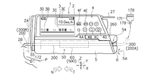
- FIG. 1 is a perspective view showing a preferred embodiment of the infusion pump of the present invention.
- FIG. 2 is a view of the infusion pump shown in FIG. 1 as viewed from the W direction.
- the infusion pump 1 shown in FIG. 1 and FIG. 2 is used for a patient, for example, an anticancer agent, an anesthetic agent, a chemotherapeutic agent or the like in an intensive care unit (ICU, CCU, NICU) or the like (also called a drug solution).
- ICU intensive care unit
- CCU CCU
- NICU chemotherapeutic agent
- This infusion pump 1 is used, for example, for selecting a drug to be used from a drug library and feeding the selected drug.
- This drug library is drug information which is a drug administration setting group including drug names registered in advance in the drug library database (DB).
- the infusion pump 1 can accurately deliver the liquid from the medicine bag 170 filled with the medicine 171 into the blood vessel of the patient P via the clamp 179, the infusion tube 200, and the indwelling needle 172. .
- the drug is also called an infusion.
- An infusion tube is also called an infusion line.
- the infusion pump 1 has a main body cover 2 and a handle 2T, and the handle 2T can be extended in the N direction or stored in the T direction.
- the main body cover 2 is also called a main body, and is integrally formed of a molded resin material having chemical resistance, and can be prevented from entering the infusion pump 1 even if a drug or the like is applied. have.
- the main body cover 2 has the drip-proof treatment structure because the medicine 171 in the medicine bag 170 disposed above spills out or disinfects the disinfecting liquid used in the vicinity. Because there is.
- a display unit 3 and an operation panel unit 4 are arranged on the upper portion 2 ⁇ / b> A of the main body cover 2.
- the display unit 3 is an image display device, and uses, for example, a color liquid crystal display device. This display unit 3 can display not only information notation in Japanese but also information in a plurality of foreign languages as required.
- the display unit 3 is disposed on the upper left side of the upper portion 2 ⁇ / b> A of the main body cover 2 and above the opening / closing cover 5.
- the upper portion 2 ⁇ / b> A of the main body cover 2 is an upper half portion of the main body cover 2.
- the lower part 2 ⁇ / b> B of the main body cover 2 is a lower half part of the main body cover 2.
- a display portion 3 for displaying information and an operation panel portion 4 having a plurality of operation buttons are arranged on the upper portion 2A of the body cover 2 of the infusion pump 1, and a lower portion 2B of the body cover 2 of the infusion pump 1 is This is a region where an infusion tube 200 which is a liquid feeding member for feeding a medicine is arranged.
- the medical worker can perform the liquid feeding operation of the medicine by the infusion pump 1 while confirming the information on the display unit 3 of the upper portion 2A of the main body cover 2.
- the medical staff can operate the operation buttons on the operation panel unit 4 while checking the information on the display unit 3 of the upper portion 2A of the main body cover 2. For this reason, the operability of the infusion pump 1 is good.
- the display unit 3 includes a display column 3B for a scheduled dose (mL) of drug administration, a display column 3C for an accumulated dose (mL) of drug administration, a display column 3D for a charge history, and a flow rate (mL / h).
- a display column 3B for a scheduled dose (mL) of drug administration
- a display column 3C for an accumulated dose (mL) of drug administration
- a display column 3D for a charge history
- a flow rate mL / h
- the display unit 3 can also display a warning message.
- the display unit 3 can change the display from, for example, a “yellow display screen” to a “white display screen” that is a warning screen for medical workers by turning on the backlight of an LED (light emitting diode). it can.
- the operation panel unit 4 is disposed on the right side of the display unit 3 in the upper part 2A of the main body cover 2, and the operation panel unit 4 includes, as an operation button, a lamp 4A (LED that functions as, for example, an operation indicator in the illustrated example. Etc., and blinks or lights green during normal operation, blinks or lights red during abnormal operation), fast-forward switch button 4B, start switch button 4C, stop switch button 4D, menu selection button 4E, power switch 4F, etc. Has been.
- a lamp 4A LED that functions as, for example, an operation indicator in the illustrated example. Etc., and blinks or lights green during normal operation, blinks or lights red during abnormal operation
- fast-forward switch button 4B start switch button 4C
- stop switch button 4D stop switch button 4D
- menu selection button 4E menu selection button 4E
- power switch 4F etc. Has been.
- an opening / closing cover 5 serving as a lid member is provided on the lower portion 2B of the main body cover 2 so as to be openable and closable in the R direction around a rotating shaft 5A.
- the open / close cover 5 is a plate-like lid member that is formed long along the X direction.
- the tube mounting part 50 and the liquid feeding drive part 60 are disposed inside the opening / closing cover 5.
- An infusion tube 200 made of a flexible thermoplastic resin such as soft vinyl chloride is set in the tube mounting portion 50, and the infusion tube 200 is connected to the tube mounting portion 50 by closing the open / close cover 5. , And can be mounted horizontally along the X direction (T direction). Note that the X direction, the Y direction, and the Z direction in FIGS.
- the X direction is parallel to the T direction, which is the liquid feeding direction, and is the left-right direction of the infusion pump 1.
- the Y direction is the front-rear direction of the infusion pump 1.
- FIG. 3 is a perspective view showing a tube mounting portion 50 for opening the opening / closing cover 5 of the infusion pump 1 shown in FIGS. 1 and 2 and mounting the infusion tube 200.
- the tube mounting part 50 and the liquid feeding drive part 60 are provided on the main body lower part 1B side of the infusion pump 1, and the tube mounting part 50 and the liquid feeding drive part 60 are operated with the display part 3.
- a lower portion of the panel portion 4 is provided along the X direction.
- the tube mounting portion 50 can cover the open / close cover 5 with the open / close cover 5 when the open / close cover 5 is closed in the CR direction around the rotation shaft 5A.
- the tube mounting portion 50 includes a bubble sensor 51, an upstream blockage sensor 52, a downstream blockage sensor 53, a tube clamp portion 270, a first infusion tube guide portion 54 at the right side position, and a left side position.
- a second infusion tube guide portion 55 is provided.
- an infusion tube setting direction display unit 150 for clearly displaying the T direction that is the correct liquid feeding direction when the infusion tube 200 is set is provided in the vicinity of the tube mounting unit 50. ing.
- the infusion tube setting direction display unit 150 includes, for example, a plurality of arrows 151.
- the infusion tube setting direction display unit 150 may be printed directly on the lower part of the tube mounting part 50, for example, or may be printed on a seal-like member and attached to the lower part of the tube mounting part 50.
- the infusion tube setting direction display unit 150 is arranged to clearly indicate the liquid feeding direction (T direction) in the correct direction of the medicine 171 by the infusion tube 200 set inside the opening / closing cover 5.
- the infusion tube 200 it is possible to clearly indicate the T direction, which is the direction of drug delivery. For this reason, it can prevent reliably that a medical worker will attach the infusion tube 200 by the reverse direction accidentally.
- the open / close cover 5 is a plate-like member made of a thin molded resin member in order to reduce the weight of the infusion pump 1. Thereby, the weight of the opening / closing cover 5 can be reduced, and the structure can be simplified.
- the opening / closing cover 5 has two hinge portions 2H and 2H that allow the tube mounting portion 50 to be covered so as to be openable and closable along the CS direction and the CR direction about the rotation shaft 5A. It is supported with respect to the main body lower part 2B.
- the two hinge portions 2H and 2H are arranged corresponding to the first hook member 5D and the second hook member 5E, respectively.
- an opening / closing operation lever 260 is provided at the upper right portion on the surface side of the opening / closing cover 5.
- an infusion tube pressing member 500 On the inner surface side of the opening / closing cover 5, an infusion tube pressing member 500, a first hook member 5D, and a second hook member 5E are provided.
- the infusion tube pressing member 500 is disposed as a long rectangular and planar protrusion along the X direction, and the infusion tube pressing member 500 is in a position facing the liquid feeding drive unit 60.
- the infusion tube pressing member 500 has a flat surface in the X direction along the liquid feeding drive unit 60, and the infusion tube pressing member 500 closes the opening / closing cover 5 in the CR direction, A part of the infusion tube 200 is pressed between them.
- the medical worker can set the infusion tube 200 on the lower half of the body of the infusion pump 1 along the horizontal direction while confirming the display content displayed on the display unit 3, and the infusion tube 200 is connected to the tube mounting portion. After being set to 50, the opening / closing cover 5 can cover the infusion tube 200.
- the first hook member 5D and the second hook member 5E are mechanically simultaneously engaged with the fixing portions 1D and 1E on the lower body 1B side, so that the open / close cover 5 is As shown, the tube mounting part 50 of the main body lower part 1B is held in a closed state.
- the first hook member 5D, the second hook member 5E, and the fixing portions 1D, 1E on the main body lower part 1B side constitute a double hook structure portion 300 of the opening / closing cover 5.
- the tube clamp part 270 shown in FIG. 3 clamps and closes the middle part of the infusion tube 200 by closing the open / close cover 5.
- the tube clamp portion 270 is disposed in the vicinity of the left fixed portion 1E and at a position corresponding to the left second hook member 5E.
- the tube clamp portion 270 can block a part of the infusion tube 200 in the middle.
- the first infusion tube guide portion 54 is provided on the right side of the main body lower portion 1B, and the second infusion tube guide portion 55 is provided on the left side of the main body lower portion 1B.
- the first infusion tube guide portion 54 can be held by fitting the upstream side 200A of the infusion tube 200
- the second infusion tube guide portion 55 can be held by fitting the downstream side 200B of the infusion tube 200
- the infusion tube 200 can be held. It is held in the horizontal direction along the X direction.
- the infusion tube 200 held in the horizontal direction is in the T direction along the bubble sensor 51, the upstream block sensor 52, the liquid feed drive unit 60, the downstream block sensor 53, and the tube clamp unit 270. It is fixed by fitting along.
- the second infusion tube guide portion 55 is a groove portion formed in the side surface portion 1 ⁇ / b> S of the main body lower portion 1 ⁇ / b> B in order to detachably hold a part of the downstream side 200 ⁇ / b> B of the infusion tube 200. is there.
- the first infusion tube guide portion 54 and the second infusion tube guide portion 55 are provided in the tube attachment portion 50 so that the infusion tube 200 is not sandwiched between the opening / closing cover 5 and the tube attachment portion 50 and crushed. Can be installed securely.
- the bubble sensor 51 shown in FIG. 3 is a sensor that detects bubbles (air) generated in the infusion tube 200.
- the bubble sensor 51 is an infusion tube such as soft vinyl chloride formed of a thermoplastic resin such as polybutadiene.
- This is an ultrasonic sensor that monitors bubbles contained in a medicine flowing into the infusion tube 200 from the outside of the infusion tube 200.
- the receiving unit monitors the presence or absence of bubbles by detecting the difference in transmittance.
- the bubble sensor 51 has a pressing member 320 and a receiving member 330.
- the ultrasonic oscillator is disposed on the pressing member 320.
- the ultrasonic wave receiver is disposed on the receiving member 330.
- the upstream blockage sensor 52 shown in FIG. 3 is a sensor that detects whether or not the inside of the infusion tube 200 is blocked on the upstream side 200A of the infusion tube 200, and the downstream blockage sensor 53 is an infusion solution on the downstream side 200B of the infusion tube 200. It is a sensor that detects whether or not the inside of the tube 200 is closed.
- the upstream blockage sensor 52 and the downstream blockage sensor 53 have the same configuration.
- the case where the infusion tube 200 is blocked is, for example, a case where the viscosity of the medicine to be delivered is high or the concentration of the medicine is high.
- pressing members 452 and 453 are provided on the inner surface side of the opening / closing cover 5 at positions corresponding to the upstream closing sensor 52 and the downstream closing sensor 53, respectively.
- the upstream occlusion sensor 52 and the downstream occlusion sensor 53 are infused by closing the open / close cover 5.
- the closed state of the tube 200 can be detected.
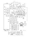
- FIG. 4 shows an electrical configuration example of the infusion pump 1.
- the infusion pump 1 has a control unit 100 that determines and controls the operation of the entire infusion pump 1.
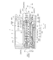
- the liquid feeding drive unit 60 includes a drive motor 61, a cam structure 62 having a plurality of cams driven to rotate by the drive motor 61, and a plurality of fingers moved by the cams of the cam structure 62.
- a finger structure 63 is provided.
- the cam structure 62 has a plurality of cams, for example, a plurality of cams 62A to 62F, and the finger structure 63 has a plurality of fingers 63A to 63F corresponding to the plurality of cams 62A to 62F.
- the plurality of cams 62A to 62F are arranged with a phase difference from each other, and the cam structure 62 is connected to the output shaft 61A of the drive motor 61.
- the liquid feeding drive unit 60 is provided on the drive motor 61 and the cam structure 62 that is supported by the output shaft 61 ⁇ / b> A when the output shaft 61 ⁇ / b> A of the drive motor 61 rotates.
- the eccentric cams 62A to 62F rotate to advance or retract the plurality of fingers 63A to 63F sequentially by a predetermined stroke (the distance between the top dead center and the bottom dead center) in the Y direction.
- a step motor is used as the drive motor 61.
- the infusion tube 200 is pressed against the infusion tube pressing member 500 of the open / close cover 5 along the T direction by the plurality of fingers 63A to 63F sequentially moving back and forth in the Y direction by a predetermined stroke. For this reason, the medicine in infusion tube 200 can be sent in the T direction. That is, when the plurality of fingers 63A to 63F are individually driven, the plurality of fingers 63A to 63F sequentially press the outer peripheral surface of the infusion tube 200 along the T direction to feed the medicine in the infusion tube 200. .
- control unit 100 controls the peristaltic motion of the plurality of fingers 63A to 63F, thereby causing the fingers 63A to 63F to move forward and backward in sequence, so that the wave travels, so that the blockage point of the infusion tube 200 is set.
- the infusion tube 200 is squeezed and the medicine is fed into the blood vessel of the patient P through the indwelling needle 172.
- the control unit 100 of the infusion pump 1 employs a CPU (central control unit) chip.
- the control unit 100 uses, for example, a one-chip microcomputer to determine and control the overall operation, and includes a ROM (read only memory) 101, a RAM (random access memory) 102, a nonvolatile memory 103, A clock 104 is included.
- the clock 104 can correct the current time by a predetermined operation, and can acquire the current time, measure the elapsed time of a predetermined liquid feeding operation, measure the reference time of liquid feeding speed control, and the like.
- a power switch button 4F includes a power switch button 4F, a power switch 111, a display driver 130 and a display 3, a drive motor 61, a speaker 131, a buzzer 132, a lamp 3W, a bubble sensor 51, and an upstream occlusion sensor. 52, downstream blockage sensor 53, communication port 140, operation panel (operation button) 4, temperature sensor 99, and information terminal 600 on the nurse center side, and manages and controls these peripheral elements. .
- the control unit 100 recognizes that a blockage has occurred in the infusion tube 200, it is a warning means for issuing a warning to a medical worker according to a command from the control unit 100.
- the medical staff can immediately recognize that the infusion tube 200 has been blocked and stop the drive motor 61 of the infusion pump 1 to stop the medicine feeding operation.
- the temperature sensor 99 detects the temperature of the environment where the infusion pump 1 is placed and sends a temperature signal TES of the control unit 100.
- the switch 111 supplies power to the control unit 100 from one of the power converter unit 112 and the battery 113 by switching between the power converter unit 112 and the battery 113.
- the power converter unit 112 is connected to a commercial AC power source 115 via an outlet 114.
- the battery 113 is a rechargeable secondary battery such as a lithium ion battery.
- the control unit 100 is also connected to the upstream block sensor 52 and the downstream block sensor 53. Thereby, the control part 100 can also monitor the obstruction
- FIG. As shown in FIGS. 4 and 5, when the infusion pump 1 is placed in a ward, for example, the information terminal 600 on the nurse center side is placed in the nurse center 650 away from the infusion pump 1.
- the display unit 3T has the same display unit 3T, lamp 3WT, speaker 131T, and buzzer 132T as the display unit 3, lamp 4A, speaker 131, and buzzer 132.
- the control unit 100 recognizes that at least one or all of the display unit 3T, the speaker 131T, the buzzer 132T, and the lamp 3WT are blocked in the infusion tube 200, the control unit 100 instructs the medical staff. This is a warning means for issuing a warning. Thereby, the medical worker in the nurse center 650 can immediately recognize that the infusion tube 200 is blocked and stop the driving motor 61 of the infusion pump 1 to stop the medicine feeding operation.
- the display unit driver 130 in FIG. 4 drives the display unit 3 in response to a command from the control unit 100, displays the information content and warning message illustrated in FIG. 2, and turns on the LED (light emitting diode) backlight.
- the display can be changed from a “yellow display screen” to a “white display screen” that is a warning screen for a medical worker. Thereby, the possibility that a medical worker can visually recognize is increased.
- the error display lamp 4 ⁇ / b> A is turned on according to a command from the control unit 100.
- the speaker 131 can notify various warning contents by voice according to the command of the control unit 100.
- the buzzer 132 can warn various warnings by sound according to a command from the control unit 100.
- the display unit 3T is driven by a command from the control unit 100 to display the information content and warning message illustrated in FIG. 2 and to turn on the backlight of the LED (light emitting diode).
- the display can be changed from the “display screen” to a “white display screen” which is a warning screen for the medical staff. Thereby, the possibility that a medical worker can visually recognize is increased.
- the error display lamp 4 ⁇ / b> A blinks or lights in red according to a command from the control unit 100.
- the speaker 131T can notify various warning contents by voice according to the command of the control unit 100.
- the buzzer 132T can warn various warnings by sound according to a command from the control unit 100.
- a downstream block signal S3 indicating that the side is blocked is supplied to the control unit 100.
- the upstream blockage sensor 52 and the downstream blockage sensor 53 can detect a state in which the internal pressure of the infusion circuit exceeds the set pressure in the infusion pump 1 and the medicine cannot be delivered.
- the reason why the internal pressure of the infusion circuit exceeds the set pressure in the infusion pump 1 is that there is a so-called “needle detachment” in which the tip of the infusion needle 172 for infusion shown in FIG.
- needle detachment in which the tip of the infusion needle 172 for infusion shown in FIG.
- the inside of the tube 200 is clogged and clogged, a part of the infusion tube 200 is crushed or broken, or a high-viscosity drug is used.
- the control unit 100 includes RS-232C (RS: Recommended Standard; a serial input / output interface of a communication system standardized by EIA (American Electronic Industry Association)), a wired communication system, a wireless LAN, an infrared communication, and the like.
- RS-232C Recommended Standard; a serial input / output interface of a communication system standardized by EIA (American Electronic Industry Association)
- a computer 141 such as a desktop computer is possible through the communication port 140.
- the computer 141 is connected to a drug database (DB) 160, and the drug library MF stored in the drug database 160 is acquired by the control unit 100 via the computer 141 as necessary, and the control unit 100 100 nonvolatile memories 103 can be stored.
- the control unit 100 can display the drug library MF and the like on the display unit 3 shown in FIG. 2, for example, based on the stored drug library MF.
- the drug information MF includes, for example, the drug manufacturer name, drug name, upper and lower limit values of the scheduled dose (m
- the upstream occlusion sensor 52 shown in FIG. 4 detects whether the infusion tube 200 is occluded on the upstream side 200 ⁇ / b> A of the infusion tube 200, and the control unit 100 detects the infusion tube 200.
- This is a sensor for sending an upstream block signal S2 indicating that the upstream side is blocked.
- the medicine 171 will flow from the medicine bag 170 filled with the medicine 171 shown in FIG. 2 into the upstream side 200A of the infusion tube 200 via the clamp 179.
- the upstream side 200A is closed and the liquid feeding drive unit 60 is driven, the portion immediately downstream of the upstream side 200A has a negative pressure.
- the downstream blockage sensor 53 detects whether or not the inside of the infusion tube 200 is blocked on the downstream side 200B of the infusion tube 200, and generates a downstream blockage signal S3 indicating that the downstream side of the infusion tube 200 is blocked. It is a sensor for sending.
- the downstream side 200B of the infusion tube 200 in FIG. 2 is blocked, the medicine 171 sent from the upstream side by the liquid feeding drive unit 60 cannot be sent due to the blocking of the downstream side 200B.
- the inside becomes positive pressure.
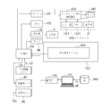
- FIG. 5 is a block diagram showing a part of the electrical configuration example of the infusion pump 1 shown in FIG. 4 in more detail.
- FIG. 6 is an exploded perspective view showing a structural example of the upstream blockage sensor 52 and the downstream blockage sensor 53.
- an applied voltage table 900 is stored in advance in the nonvolatile memory 103 of the control unit 100, for example.
- a temperature sensor 99 is connected to the control unit 100.
- the upstream blockage sensor 52 and the downstream blockage sensor 53 have the same structure.
- a hole 400 is provided in the surface 50 ⁇ / b> S of the tube mounting portion 50.
- a plastic frame member 401 is fitted into the hole 400, and the frame member 401 has a rectangular opening 402.
- the plastic plunger 403 is inserted into the receiving hole 404 in the hole 400, and the plunger 403 has a base 405, a tip 406, and a spring 407.
- the distal end 406 of the plunger 403 is fitted in the opening 402.
- One end of the spring 407 is attached to the base 405, and the other end of the spring 407 is attached to the protrusion 409 in the accommodation hole 404.
- a Hall element 410 is disposed on the inner surface of the accommodation hole 404.
- Two magnets 411 and 412 are arranged on the base 405.
- the upstream blockage sensor 52 is simply installed by inserting the frame member 401 into the hole 400 and inserting the base 405 into the opening 402 and the accommodation hole 404 while holding the spring 407.
- the downstream blockage sensor 53 can be easily mounted on the surface 50S of the tube mounting portion 50, and the assembly workability of the upstream blockage sensor 52 and the downstream blockage sensor 53 can be improved.
- pressing members 452 and 453 are provided on the inner surface side of the opening / closing cover 5 at positions corresponding to the upstream closing sensor 52 and the downstream closing sensor 53, respectively.
- the pressing members 452 and 453 are structured to be pressed toward the frame member 401 facing each other through the spring 441.
- the pressing member 452 is a first pressing member
- the pressing member 453 is a second pressing member.
- the infusion tube 200 can be The upstream occlusion sensor 52 and the downstream occlusion sensor 53 are always pressed against the infusion tube 200 so that the occlusion state of the infusion tube 200 can be accurately detected.
- the upstream blockage sensor 52 and the downstream blockage sensor 53 will be described more specifically.
- the infusion tube 200 is moved between the pressing member 452 (453) and the tip 406 of the plunger 403 as shown in FIG. It is sandwiched and held by each urging force 441.
- the plunger 403 is an example of a moving member that can move linearly with respect to the Hall element 410. If the diameter of the infusion tube 200 is changed due to the blockage of the infusion tube 200, the tip 406 moves in the Y direction following the change in the diameter of the infusion tube 200. For this reason, since the magnets 411 and 412 move relative to the Hall element 410, the Hall element 410 detects a change in magnetic flux and determines the movement distance of the plunger 403 with respect to the control unit 100. Can be sent as a signal.
- the center axis direction of the spring 441 and the center axis direction of the spring 407 coincide with each other, and the springs 441 and 407 sandwich the infusion tube 200 between the pressing member 452 (453) and the distal end portion 406.
- the occlusion state of the infusion tube 200 can be detected with high accuracy by detecting the movement distance of the plunger 403 that forms the occlusion sensors 52 and 53.
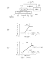
- FIG. 7A shows the magnets 411 and 412 and the Hall element 410 arranged on the base 405 of the plunger 403 shown in FIG.
- the magnets 411 and 412 arranged in the base 405 are movable bodies that can move in the Y direction, and the Hall element 410 is a fixed body. For this reason, when the diameter of the infusion tube 200 changes due to the blockage of the infusion tube 200, the tip 406 in FIG. 6 moves in the Y direction following the change in the diameter of the infusion tube 200, so that the magnets 411, 412 Moves relative to the Hall element 410 along the Y direction.
- the Hall element 410 detects a change in magnetic flux by the linear movement of the magnets 411 and 412 in the Y direction.
- the applied voltage BE is supplied from the control unit 100 to the Hall element 410, and the Hall element 410 detects a change in magnetic flux from the magnets 411 and 412, so that the output voltage PV of the Hall element 410 is sent to the control unit 100. It is done.
- the output voltage PV of the Hall element 410 is proportional to the moving distance of the plunger 403 in the Y direction. It should be noted that the slopes of the output voltage PV in FIGS. 7B and 7C may be reversed (slopes to the right).
- FIGS. 7B and 7 (C) show the output voltage PV of the Hall element 410 of the upstream blockage sensor 52 and the downstream blockage sensor 53, and the swelling of the outer diameter (about 3.3 mm) of the infusion tube 200 accompanying the blockage (
- An example of the relationship of the movement distance DL of the plunger 403 corresponding to an increase in outer diameter of about 0.2 mm in diameter expansion) is shown.
- the relationship between the output voltage PV of the Hall element 410 and the movement distance DL of the plunger 403 is substantially the same, and the output voltage PV is linear.
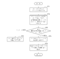
- FIG. 8 shows that when the upstream blockage sensor 52 and the downstream blockage sensor 53 are assembled and mounted on the infusion pump 1, the relationship between the output voltage PV of the Hall element 410 and the movement distance DL of the plunger 403 has an appropriate sensitivity. A procedure for setting a linear relationship is shown.
- step ST1 shown in FIG. 8 when the assembly operator assembles the upstream closing sensor 52 and the downstream closing sensor 53, the hall element 410 is moved into a predetermined hole in the accommodation hole 404 in the hole 400. The position is fixed. Since the Hall element 410 is electrically connected to the control unit 100, the control unit 100 can supply the applied voltage BE to the Hall element 410 as illustrated in FIG. As shown in FIG. 6, the assembly operator inserts the plunger 403 into the accommodation hole 404 in the hole 400, and inserts the tip 406 of the plunger 403 into the opening 402 of the frame member 401. One end of the spring 407 is attached to the base 405, and the other end of the spring 407 is attached to the protrusion 409 in the accommodation hole 404.
- step ST2 of FIG. 8 when the assembly operator manually moves the plunger 403 shown in FIG. 6 in the Y direction against the force of the spring 407, the movement distance of the plunger 403 as illustrated in FIG.
- the DL is sequentially moved and positioned along, for example, four predetermined movement distance positions D1, D2, D3, and D4 along the Y direction.
- the control unit 100 in FIG. 5 refers to the applied voltage table 900 and supplies the applied voltages BE1 to BE16 stored in the applied voltage table 900 to the Hall element 410. That is, when the movement distance DL of the plunger 403 is positioned at the movement distance position D1, the control unit 100 supplies the applied voltages BE1 to BE4 to the Hall element 410.
- the control unit 100 supplies the applied voltages BE5 to BE8 to the Hall element 410.
- the control unit 100 supplies the applied voltages BE9 to BE12 to the Hall element 410.
- the control unit 100 supplies the applied voltages BE13 to BE16 to the Hall element 410.
- step ST3 of FIG. 8, in FIG. 9, the control unit 100 selects the applied voltage BE2 at the time when the movement distance DL of the plunger 403 is positioned at the movement distance position D1, thereby outputting the output voltage of the Hall element. PV1 is obtained.
- the output voltage PV2 of the Hall element is obtained by selecting the applied voltage BE7.
- the applied voltage BE10 is selected to obtain the output voltage PV3 of the Hall element.
- the applied voltage BE15 is selected to obtain the output voltage PV4 of the Hall element.
- the movement distance DL of the plunger 403 obtains an accurate linearity as shown by the straight line LL from the relationship between the output voltages PV1, PV2, PV3, and PV4 of the Hall elements with respect to the movement distance positions D1, D2, D3, and D4. Can do.
- the control unit 100 can obtain the output voltage PV of the Hall element corresponding to the position at any position of the movement distance DL of the plunger 403 from the straight line LL obtained in this way.
- the movement distance DL is set to be about twice as large as the output voltage PV from which a more linear output can be obtained.
- the distance of the straight section FH that can be used for detection by the plunger 403 is set to be 2 to 3 times the bulge amount (expansion diameter ⁇ ) of the infusion tube 200. If it is smaller than twice, it becomes as shown in FIG. 7B, and it becomes difficult to detect the closed state. On the other hand, if it exceeds three times, the dimension of the plunger 403 in the Y direction becomes large, which is not preferable.
- the infusion tube 200 when it is smaller than the movement distance position D1 and / or the output voltage is out of the linear region, the infusion tube 200 is not securely attached to the tube attachment part 50 of the liquid delivery drive part 60, or the liquid delivery operation is performed. A state where the infusion tube 200 is detached from the tube mounting portion 50 of the liquid feeding drive portion 60 which is a predetermined position where the infusion tube 200 should be mounted (set) is detected, an alarm is generated, and the drive motor is stopped. it can.
- step ST3 as a result of the determination in the control unit 100, the relationship between the increase in the movement distance DL of the plunger 403 and the increase in the output voltage PV of the Hall element 410 is linear, and the Hall elements of the upstream block sensor 52 and the downstream block sensor 53 If the relationship between the output voltage PV 410 and the movement distance DL of the plunger 403 can be set to a linear relationship having an appropriate sensitivity rather than a sensitivity that is too high or too low, the process proceeds to step ST4.
- step ST4 the assembly operator can employ the assembly of the plunger 403 and the hall element 410, and in step ST5, the upstream block sensor 52 and the downstream block sensor 53 can be assembled as shown in FIG. By doing so, the setting operation of the plunger 403 can be performed with certainty, and therefore the time for incorporating and setting the upstream blockage sensor 52 and the downstream blockage sensor 53 can be shortened.
- step ST3 as a result of the determination by the control unit 100, if the relationship between the increase in the movement distance DL of the plunger 403 and the increase in the output voltage PV of the hall element 410 is not linear, the plunger 403 and the hall element 410 The assembly is not adopted as a defective product. For example, another plunger 403 is prepared, and steps ST1 to ST3 in FIG. 8 are executed using the separately prepared assembly of the plunger 403 and the hall element 410.
- the infusion tube 200 is a case where the internal pressure which generate
- the infusion tube 200 is formed of a thermoplastic resin such as polybutadiene, etc., and tends to soften when the temperature increases, and conversely, cure when the temperature decreases.
- the infusion tube 200 is likely to swell when the temperature of the environment where the infusion pump 1 is placed becomes high, and conversely, the temperature of the environment where the infusion pump 1 is located The lower infusion tube 200 is less likely to swell.
- a temperature sensor 99 such as a thermistor illustrated in FIG. 5 is preferably provided in order to detect the operating environment temperature of the infusion pump 1.
- the operating environment temperature detected by the temperature sensor 99 is, for example, between 0 and 40 ° C., and the temperature range is 5 ° C. every time the closing pressure detection threshold (the threshold of the movement distance of the plunger 403 forming the closing sensors 52 and 53 is detected). ) Can be detected with high accuracy. For example, assuming that the moving distance of the plunger 403 at 20 to 25 ° C. at a constant pressure is 1, the moving distance of the plunger 403 at 15 to 20 ° C. is 0.99, and the plunger 403 at 10 to 15 ° C.
- Plunger 403 when the moving distance is 0.98 the moving distance of the plunger 403 is 0.97 when the moving distance is 0 to 10 ° C.
- the moving distance of the plunger 403 is 1.01 when the moving distance is 25 to 30 ° C.
- the plunger 403 when the moving distance is 30 to 35 ° C. Is stored in a ROM (read only memory) 101 as a moving distance of 1.02, and the threshold value is changed.
- the occlusion pressure in the infusion tube 200 can be detected at a substantially constant level corresponding to the swell and contraction of the infusion tube 200.
- the correction may be made by making the temperature range larger than 5 ° C. However, in this case, the sensitivity of the blockage detection is slightly lowered. Further, the temperature range may be corrected by making it smaller than 5 ° C., but in this case, the storage capacity of the ROM (read only memory) 101 is increased.
- the usage example of the infusion pump 1 mentioned above is demonstrated easily.
- the infusion tube setting direction display unit 150 is viewed to visually set the infusion tube 200.
- the medical staff places the upstream side 200A of the infusion tube 200 on the first infusion tube guide part 54 side of the right side toward the main body part 1B, and faces the downstream side 200B of the infusion tube 200 in the main body part 1B. And placed on the second infusion tube guide 55 side of the left side portion.
- the medical staff can replace the infusion tube 200 with the first infusion tube guide portion 54, the bubble sensor 51, the upstream occlusion sensor 52, the liquid feeding drive portion 60, the downstream occlusion sensor 53, the tube clamp portion 270, and It can be set in the T direction along the second infusion tube guide portion 55.
- the open / close cover 5 is closed to cover the bubble sensor 51, the upstream block sensor 52, the downstream block sensor 53, the liquid feeding drive unit 60, and the tube clamp unit 270.
- the infusion tube 200 can be set along the T direction which is the correct direction, and the medicine can be fed along the T direction through the infusion tube 200 by driving the liquid feeding drive unit 60.
- An infusion pump 1 is an infusion pump for delivering a medicine into a blood vessel of a patient using an infusion tube, and an occlusion sensor that detects occlusion of the infusion tube when the medicine is delivered. And a control unit to which the output voltage of the blockage sensor is supplied.
- the blockage sensor has a plurality of magnets and is arranged to be linearly movable, and is fixed to the main body side of the infusion pump.
- the control unit applies a plurality of predetermined applied voltages to the Hall element for each moving distance of the plurality of positions when the moving member increases the moving distance to the plurality of predetermined positions. do it By selecting from among a plurality of imparting voltages applied to each moving distance of the plurality of positions, to obtain the linearity of the output voltage of the Hall element with respect to the movement distance of the plurality of positions.
- the control unit applies a plurality of predetermined application voltages to the Hall element for each of the movement distances of the plurality of positions.
- linearity of the output voltage of the Hall element with respect to the movement distance of the plurality of positions is obtained.
- the control unit has an applied voltage table that stores a plurality of applied voltages determined in advance for each moving distance of a plurality of positions. Thereby, the control unit can give a plurality of predetermined application voltages to the Hall element for each moving distance of a plurality of positions by referring to the application voltage table, and block the change in the diameter of the infusion tube. The linearity of the output voltage of the Hall element of the sensor can be easily obtained.
- the occlusion sensor When the occlusion sensor detects the occlusion of the infusion tube, it has a warning means that issues a warning according to the command of the control unit, so that the medical worker can know the occlusion state of the infusion tube by the warning.
- the liquid feeding operation can be stopped immediately. It has a temperature sensor that detects the environmental temperature of the infusion tube, and the control unit changes the threshold of the moving distance of the moving member according to the value of the environmental temperature by the signal from the temperature sensor.
- the blockage of the infusion tube can be detected according to the bulging state of the infusion tube in the radial direction.
- a display unit for displaying information and an operation panel unit having operation buttons are arranged on the upper part of the body of the infusion pump, and an infusion tube for delivering a medicine is arranged on the lower part of the body of the infusion pump. It is an area.
- the medical worker can perform the liquid feeding operation of the medicine by the infusion pump while confirming the information on the display unit on the upper part of the main body.
- the medical worker can operate the operation buttons on the operation panel unit while confirming the information on the display unit on the upper part of the main body.
- the infusion pump of the present invention can be applied for blood feeding (blood transfusion) in addition to drug feeding and for feeding nutrients from the intestinal tract.
Abstract
Priority Applications (5)
| Application Number | Priority Date | Filing Date | Title |
|---|---|---|---|
| JP2014537844A JP6207516B2 (ja) | 2012-09-27 | 2012-09-27 | 輸液ポンプ |
| PCT/JP2012/006216 WO2014049660A1 (fr) | 2012-09-27 | 2012-09-27 | Pompe à perfusion |
| CN201280075475.6A CN104602726B (zh) | 2012-09-27 | 2012-09-27 | 输液泵 |
| EP12885703.4A EP2902048B1 (fr) | 2012-09-27 | 2012-09-27 | Pompe à perfusion |
| US14/664,396 US10022494B2 (en) | 2012-09-27 | 2015-03-20 | Infusion pump |
Applications Claiming Priority (1)
| Application Number | Priority Date | Filing Date | Title |
|---|---|---|---|
| PCT/JP2012/006216 WO2014049660A1 (fr) | 2012-09-27 | 2012-09-27 | Pompe à perfusion |
Related Child Applications (1)
| Application Number | Title | Priority Date | Filing Date |
|---|---|---|---|
| US14/664,396 Continuation US10022494B2 (en) | 2012-09-27 | 2015-03-20 | Infusion pump |
Publications (1)
| Publication Number | Publication Date |
|---|---|
| WO2014049660A1 true WO2014049660A1 (fr) | 2014-04-03 |
Family
ID=50387129
Family Applications (1)
| Application Number | Title | Priority Date | Filing Date |
|---|---|---|---|
| PCT/JP2012/006216 WO2014049660A1 (fr) | 2012-09-27 | 2012-09-27 | Pompe à perfusion |
Country Status (5)
| Country | Link |
|---|---|
| US (1) | US10022494B2 (fr) |
| EP (1) | EP2902048B1 (fr) |
| JP (1) | JP6207516B2 (fr) |
| CN (1) | CN104602726B (fr) |
| WO (1) | WO2014049660A1 (fr) |
Cited By (5)
| Publication number | Priority date | Publication date | Assignee | Title |
|---|---|---|---|---|
| JP2016019629A (ja) * | 2014-07-14 | 2016-02-04 | ミネベア株式会社 | 閉塞検出装置及び輸液装置 |
| JP2018521823A (ja) * | 2015-07-24 | 2018-08-09 | ゼヴェクス・インコーポレーテッド | 輸液ポンプ用磁式圧力感知システム |
| CN112105405A (zh) * | 2018-05-15 | 2020-12-18 | 巴克斯特国际公司 | 具有管装载引导和确认的输液泵 |
| EP3888726A4 (fr) * | 2019-01-22 | 2022-01-19 | TERUMO Kabushiki Kaisha | Pompe de distribution de liquide |
| WO2023149344A1 (fr) * | 2022-02-02 | 2023-08-10 | テルモ株式会社 | Pompe à perfusion |
Families Citing this family (37)
| Publication number | Priority date | Publication date | Assignee | Title |
|---|---|---|---|---|
| EP3760180A3 (fr) | 2009-07-29 | 2021-01-20 | ICU Medical, Inc. | Methode du transfert de fluides |
| MX352572B (es) | 2011-12-22 | 2017-11-29 | Icu Medical Inc | Dispositivos de transferencia de fluidos y metodos de uso. |
| USD767756S1 (en) | 2013-06-11 | 2016-09-27 | Deka Products Limited Partnership | Medical pump |
| USD735319S1 (en) | 2013-06-11 | 2015-07-28 | Deka Products Limited Partnership | Medical pump |
| USD736370S1 (en) | 2013-06-11 | 2015-08-11 | Deka Products Limited Partnership | Medical pump |
| WO2015077184A1 (fr) | 2013-11-25 | 2015-05-28 | Icu Medical, Inc. | Procédés et système pour remplir des sacs pour perfusion intraveineuse d'un fluide thérapeutique |
| USD760782S1 (en) | 2013-12-20 | 2016-07-05 | Deka Products Limited Partnership | Display screen of a medical pump with a graphical user interface |
| USD803387S1 (en) * | 2015-02-10 | 2017-11-21 | Deka Products Limited Partnership | Syringe medical pump |
| USD801519S1 (en) * | 2015-02-10 | 2017-10-31 | Deka Products Limited Partnership | Peristaltic medical pump |
| USD803386S1 (en) * | 2015-02-10 | 2017-11-21 | Deka Products Limited Partnership | Syringe medical pump |
| USD805183S1 (en) * | 2015-02-10 | 2017-12-12 | Deka Products Limited Partnership | Medical pump |
| USD894373S1 (en) * | 2015-09-30 | 2020-08-25 | Fresenius Vial Sas | Syringe pump |
| AU2016365335B2 (en) | 2015-12-04 | 2021-10-21 | Icu Medical, Inc. | Systems methods and components for transferring medical fluids |
| ES2960055T3 (es) | 2016-06-16 | 2024-02-29 | Smiths Medical Asd Inc | Conjuntos y métodos para conjuntos de administración de sistema de bomba de infusión |
| USD851745S1 (en) | 2016-07-19 | 2019-06-18 | Icu Medical, Inc. | Medical fluid transfer system |
| AU2017302557B2 (en) | 2016-07-25 | 2022-10-13 | Icu Medical, Inc. | Systems, methods, and components for trapping air bubbles in medical fluid transfer modules and systems |
| USD812218S1 (en) * | 2016-11-04 | 2018-03-06 | Smiths Medical Asd, Inc. | Large volume pump |
| USD828547S1 (en) * | 2016-11-04 | 2018-09-11 | Smiths Medical Asd, Inc. | Syringe pump |
| USD816696S1 (en) | 2016-11-08 | 2018-05-01 | Smiths Medical Asd, Inc. | Display screen or portion thereof with graphical user interface |
| USD816697S1 (en) | 2016-11-08 | 2018-05-01 | Smiths Medical Asd, Inc. | Display screen or portion thereof with graphical user interface |
| USD816700S1 (en) * | 2016-11-29 | 2018-05-01 | Smiths Medical Asd, Inc. | Display screen or portion thereof with graphical user interface |
| USD816699S1 (en) | 2016-11-29 | 2018-05-01 | Smiths Medical Asd, Inc. | Display screen or portion thereof with graphical user interface |
| USD830546S1 (en) * | 2016-11-30 | 2018-10-09 | Smiths Medical Asd, Inc. | Receptacle area of infusion pump |
| USD846735S1 (en) | 2016-12-02 | 2019-04-23 | Smiths Medical Asd, Inc. | Plunger driver head for syringe pump |
| USD823456S1 (en) | 2016-12-05 | 2018-07-17 | Smiths Medical Asd, Inc. | Control panel for infusion pump |
| USD828366S1 (en) | 2016-12-15 | 2018-09-11 | Smiths Medical Asd, Inc. | Display screen or portion thereof with graphical user interface |
| DE102017111301A1 (de) * | 2017-05-23 | 2018-11-29 | B. Braun Melsungen Ag | Sensorsystem |
| CN110944697B (zh) | 2017-07-19 | 2022-09-09 | 史密斯医疗Asd公司 | 输液泵的壳体布置 |
| USD870263S1 (en) | 2017-07-26 | 2019-12-17 | Smiths Medical Asd, Inc. | Infusion set |
| US11324885B2 (en) | 2017-11-16 | 2022-05-10 | Fresenius Vial Sas | Infusion device and method for administering a medical fluid to a patient |
| EP3705148A1 (fr) | 2019-03-04 | 2020-09-09 | Avoset Health Ltd. | Mesure cyclique de la pression |
| US11890451B2 (en) | 2019-03-05 | 2024-02-06 | Eitan Medical Ltd. | Anti-free-flow valve |
| JPWO2021182123A1 (fr) * | 2020-03-11 | 2021-09-16 | ||
| US11590057B2 (en) | 2020-04-03 | 2023-02-28 | Icu Medical, Inc. | Systems, methods, and components for transferring medical fluids |
| CN111658548B (zh) * | 2020-06-03 | 2023-03-14 | 上海安洁电子设备有限公司 | 一种营养泵的阻塞检测装置、检测方法及营养泵 |
| USD989278S1 (en) * | 2020-10-19 | 2023-06-13 | Walmart Apollo, Llc | Body temperature screening control unit |
| WO2022159487A1 (fr) * | 2021-01-19 | 2022-07-28 | CHS Healthcare Ventures, Inc | Procédé et fabrication d'une ligne de perfusion médicale à fibre optique à deux lumières |
Citations (5)
| Publication number | Priority date | Publication date | Assignee | Title |
|---|---|---|---|---|
| JPH01249064A (ja) * | 1988-03-30 | 1989-10-04 | Nikkiso Co Ltd | 輸液管の閉塞状態検出装置 |
| JPH0630993A (ja) * | 1992-07-13 | 1994-02-08 | Terumo Corp | 輸液ポンプ用の閉塞検知装置 |
| JPH06254159A (ja) * | 1993-03-01 | 1994-09-13 | Terumo Corp | 輸液ポンプ用の閉塞検知装置 |
| JPH11508017A (ja) * | 1996-04-10 | 1999-07-13 | バクスター・インターナショナル・インコーポレイテッド | 容量注入ポンプ |
| JP2010200775A (ja) | 2009-02-27 | 2010-09-16 | Terumo Corp | 医療用ポンプと医療用ポンプの点検装置 |
Family Cites Families (7)
| Publication number | Priority date | Publication date | Assignee | Title |
|---|---|---|---|---|
| JPS5631758A (en) * | 1979-08-24 | 1981-03-31 | Sharp Kk | Detector for clogging condition of flexible tube |
| US4936760A (en) * | 1989-06-12 | 1990-06-26 | Williams David R | Volumetric infusion pump |
| US6213723B1 (en) * | 1996-06-24 | 2001-04-10 | Baxter International Inc. | Volumetric infusion pump |
| US7621893B2 (en) * | 1998-10-29 | 2009-11-24 | Medtronic Minimed, Inc. | Methods and apparatuses for detecting occlusions in an ambulatory infusion pump |
| JP5684442B2 (ja) * | 2007-04-02 | 2015-03-11 | 日産自動車株式会社 | 磁気センサ装置 |
| JP5715235B2 (ja) * | 2010-04-01 | 2015-05-07 | ウー ヨン メディカル カンパニーリミテッド | 輸液装置 |
| JP2012029914A (ja) * | 2010-07-30 | 2012-02-16 | Terumo Corp | 輸液ポンプ |
-
2012
- 2012-09-27 EP EP12885703.4A patent/EP2902048B1/fr active Active
- 2012-09-27 CN CN201280075475.6A patent/CN104602726B/zh active Active
- 2012-09-27 JP JP2014537844A patent/JP6207516B2/ja active Active
- 2012-09-27 WO PCT/JP2012/006216 patent/WO2014049660A1/fr active Application Filing
-
2015
- 2015-03-20 US US14/664,396 patent/US10022494B2/en active Active
Patent Citations (5)
| Publication number | Priority date | Publication date | Assignee | Title |
|---|---|---|---|---|
| JPH01249064A (ja) * | 1988-03-30 | 1989-10-04 | Nikkiso Co Ltd | 輸液管の閉塞状態検出装置 |
| JPH0630993A (ja) * | 1992-07-13 | 1994-02-08 | Terumo Corp | 輸液ポンプ用の閉塞検知装置 |
| JPH06254159A (ja) * | 1993-03-01 | 1994-09-13 | Terumo Corp | 輸液ポンプ用の閉塞検知装置 |
| JPH11508017A (ja) * | 1996-04-10 | 1999-07-13 | バクスター・インターナショナル・インコーポレイテッド | 容量注入ポンプ |
| JP2010200775A (ja) | 2009-02-27 | 2010-09-16 | Terumo Corp | 医療用ポンプと医療用ポンプの点検装置 |
Cited By (6)
| Publication number | Priority date | Publication date | Assignee | Title |
|---|---|---|---|---|
| JP2016019629A (ja) * | 2014-07-14 | 2016-02-04 | ミネベア株式会社 | 閉塞検出装置及び輸液装置 |
| JP2018521823A (ja) * | 2015-07-24 | 2018-08-09 | ゼヴェクス・インコーポレーテッド | 輸液ポンプ用磁式圧力感知システム |
| CN112105405A (zh) * | 2018-05-15 | 2020-12-18 | 巴克斯特国际公司 | 具有管装载引导和确认的输液泵 |
| CN112105405B (zh) * | 2018-05-15 | 2023-08-01 | 巴克斯特国际公司 | 具有管装载引导和确认的输液泵 |
| EP3888726A4 (fr) * | 2019-01-22 | 2022-01-19 | TERUMO Kabushiki Kaisha | Pompe de distribution de liquide |
| WO2023149344A1 (fr) * | 2022-02-02 | 2023-08-10 | テルモ株式会社 | Pompe à perfusion |
Also Published As
| Publication number | Publication date |
|---|---|
| CN104602726A (zh) | 2015-05-06 |
| EP2902048A1 (fr) | 2015-08-05 |
| JPWO2014049660A1 (ja) | 2016-08-18 |
| EP2902048A4 (fr) | 2016-05-18 |
| EP2902048B1 (fr) | 2017-06-14 |
| US20150314066A1 (en) | 2015-11-05 |
| CN104602726B (zh) | 2017-05-24 |
| JP6207516B2 (ja) | 2017-10-04 |
| US10022494B2 (en) | 2018-07-17 |
Similar Documents
| Publication | Publication Date | Title |
|---|---|---|
| JP6207516B2 (ja) | 輸液ポンプ | |
| JP6433294B2 (ja) | 輸液ポンプ | |
| US10010686B2 (en) | Fluid control system and disposable assembly | |
| US20110028937A1 (en) | Automated fluid flow control system | |
| AU2014348700B2 (en) | Fluid control system and disposable assembly | |
| WO2012144219A1 (fr) | Pompe de perfusion | |
| JP6240620B2 (ja) | 点滴プローブと点滴プローブを備える輸液ポンプ | |
| JP5805415B2 (ja) | 輸液ポンプ | |
| JP5996843B2 (ja) | 輸液ポンプ | |
| WO2014049656A1 (fr) | Pompe de perfusion | |
| JP3124022U (ja) | 輸液装置 | |
| JP5897815B2 (ja) | 輸液ポンプ | |
| JP5740187B2 (ja) | 輸液ポンプ | |
| JP6285369B2 (ja) | 輸液ポンプ | |
| WO2014049657A1 (fr) | Pompe à usage médical | |
| WO2023149344A1 (fr) | Pompe à perfusion | |
| WO2014045328A1 (fr) | Pompe de perfusion | |
| WO2013125576A1 (fr) | Pompe médicale | |
| JP2012200422A (ja) | 輸液ポンプ | |
| WO2014045323A1 (fr) | Pompe médicale | |
| JP2018157934A (ja) | クランプ形態検知システム及びクランプ形態検知装置 | |
| WO2014020636A1 (fr) | Pompe à perfusion |
Legal Events
| Date | Code | Title | Description |
|---|---|---|---|
| 121 | Ep: the epo has been informed by wipo that ep was designated in this application |
Ref document number: 12885703 Country of ref document: EP Kind code of ref document: A1 |
|
| ENP | Entry into the national phase |
Ref document number: 2014537844 Country of ref document: JP Kind code of ref document: A |
|
| REEP | Request for entry into the european phase |
Ref document number: 2012885703 Country of ref document: EP |
|
| WWE | Wipo information: entry into national phase |
Ref document number: 2012885703 Country of ref document: EP |
|
| NENP | Non-entry into the national phase |
Ref country code: DE |