WO2014046274A1 - 光ファイバの製造方法 - Google Patents
光ファイバの製造方法 Download PDFInfo
- Publication number
- WO2014046274A1 WO2014046274A1 PCT/JP2013/075611 JP2013075611W WO2014046274A1 WO 2014046274 A1 WO2014046274 A1 WO 2014046274A1 JP 2013075611 W JP2013075611 W JP 2013075611W WO 2014046274 A1 WO2014046274 A1 WO 2014046274A1
- Authority
- WO
- WIPO (PCT)
- Prior art keywords
- optical fiber
- temperature
- heating furnace
- furnace
- slow cooling
- Prior art date
Links
Images

Classifications
-
- C—CHEMISTRY; METALLURGY
- C03—GLASS; MINERAL OR SLAG WOOL
- C03B—MANUFACTURE, SHAPING, OR SUPPLEMENTARY PROCESSES
- C03B37/00—Manufacture or treatment of flakes, fibres, or filaments from softened glass, minerals, or slags
- C03B37/01—Manufacture of glass fibres or filaments
- C03B37/02—Manufacture of glass fibres or filaments by drawing or extruding, e.g. direct drawing of molten glass from nozzles; Cooling fins therefor
- C03B37/025—Manufacture of glass fibres or filaments by drawing or extruding, e.g. direct drawing of molten glass from nozzles; Cooling fins therefor from reheated softened tubes, rods, fibres or filaments, e.g. drawing fibres from preforms
- C03B37/027—Fibres composed of different sorts of glass, e.g. glass optical fibres
- C03B37/02718—Thermal treatment of the fibre during the drawing process, e.g. cooling
- C03B37/02727—Annealing or re-heating
-
- C—CHEMISTRY; METALLURGY
- C03—GLASS; MINERAL OR SLAG WOOL
- C03B—MANUFACTURE, SHAPING, OR SUPPLEMENTARY PROCESSES
- C03B37/00—Manufacture or treatment of flakes, fibres, or filaments from softened glass, minerals, or slags
- C03B37/01—Manufacture of glass fibres or filaments
- C03B37/02—Manufacture of glass fibres or filaments by drawing or extruding, e.g. direct drawing of molten glass from nozzles; Cooling fins therefor
- C03B37/025—Manufacture of glass fibres or filaments by drawing or extruding, e.g. direct drawing of molten glass from nozzles; Cooling fins therefor from reheated softened tubes, rods, fibres or filaments, e.g. drawing fibres from preforms
- C03B37/027—Fibres composed of different sorts of glass, e.g. glass optical fibres
- C03B37/02718—Thermal treatment of the fibre during the drawing process, e.g. cooling
-
- C—CHEMISTRY; METALLURGY
- C03—GLASS; MINERAL OR SLAG WOOL
- C03B—MANUFACTURE, SHAPING, OR SUPPLEMENTARY PROCESSES
- C03B37/00—Manufacture or treatment of flakes, fibres, or filaments from softened glass, minerals, or slags
- C03B37/01—Manufacture of glass fibres or filaments
- C03B37/02—Manufacture of glass fibres or filaments by drawing or extruding, e.g. direct drawing of molten glass from nozzles; Cooling fins therefor
- C03B37/025—Manufacture of glass fibres or filaments by drawing or extruding, e.g. direct drawing of molten glass from nozzles; Cooling fins therefor from reheated softened tubes, rods, fibres or filaments, e.g. drawing fibres from preforms
- C03B37/0253—Controlling or regulating
-
- C—CHEMISTRY; METALLURGY
- C03—GLASS; MINERAL OR SLAG WOOL
- C03C—CHEMICAL COMPOSITION OF GLASSES, GLAZES OR VITREOUS ENAMELS; SURFACE TREATMENT OF GLASS; SURFACE TREATMENT OF FIBRES OR FILAMENTS MADE FROM GLASS, MINERALS OR SLAGS; JOINING GLASS TO GLASS OR OTHER MATERIALS
- C03C25/00—Surface treatment of fibres or filaments made from glass, minerals or slags
- C03C25/002—Thermal treatment
-
- C—CHEMISTRY; METALLURGY
- C03—GLASS; MINERAL OR SLAG WOOL
- C03C—CHEMICAL COMPOSITION OF GLASSES, GLAZES OR VITREOUS ENAMELS; SURFACE TREATMENT OF GLASS; SURFACE TREATMENT OF FIBRES OR FILAMENTS MADE FROM GLASS, MINERALS OR SLAGS; JOINING GLASS TO GLASS OR OTHER MATERIALS
- C03C25/00—Surface treatment of fibres or filaments made from glass, minerals or slags
- C03C25/60—Surface treatment of fibres or filaments made from glass, minerals or slags by diffusing ions or metals into the surface
- C03C25/607—Surface treatment of fibres or filaments made from glass, minerals or slags by diffusing ions or metals into the surface in the gaseous phase
-
- G—PHYSICS
- G02—OPTICS
- G02B—OPTICAL ELEMENTS, SYSTEMS OR APPARATUS
- G02B6/00—Light guides; Structural details of arrangements comprising light guides and other optical elements, e.g. couplings
- G02B6/10—Light guides; Structural details of arrangements comprising light guides and other optical elements, e.g. couplings of the optical waveguide type
-
- C—CHEMISTRY; METALLURGY
- C03—GLASS; MINERAL OR SLAG WOOL
- C03B—MANUFACTURE, SHAPING, OR SUPPLEMENTARY PROCESSES
- C03B2201/00—Type of glass produced
- C03B2201/06—Doped silica-based glasses
- C03B2201/30—Doped silica-based glasses doped with metals, e.g. Ga, Sn, Sb, Pb or Bi
- C03B2201/31—Doped silica-based glasses doped with metals, e.g. Ga, Sn, Sb, Pb or Bi doped with germanium
-
- C—CHEMISTRY; METALLURGY
- C03—GLASS; MINERAL OR SLAG WOOL
- C03B—MANUFACTURE, SHAPING, OR SUPPLEMENTARY PROCESSES
- C03B2203/00—Fibre product details, e.g. structure, shape
- C03B2203/10—Internal structure or shape details
- C03B2203/22—Radial profile of refractive index, composition or softening point
-
- C—CHEMISTRY; METALLURGY
- C03—GLASS; MINERAL OR SLAG WOOL
- C03B—MANUFACTURE, SHAPING, OR SUPPLEMENTARY PROCESSES
- C03B2205/00—Fibre drawing or extruding details
- C03B2205/55—Cooling or annealing the drawn fibre prior to coating using a series of coolers or heaters
-
- C—CHEMISTRY; METALLURGY
- C03—GLASS; MINERAL OR SLAG WOOL
- C03B—MANUFACTURE, SHAPING, OR SUPPLEMENTARY PROCESSES
- C03B2205/00—Fibre drawing or extruding details
- C03B2205/56—Annealing or re-heating the drawn fibre prior to coating
-
- C—CHEMISTRY; METALLURGY
- C03—GLASS; MINERAL OR SLAG WOOL
- C03B—MANUFACTURE, SHAPING, OR SUPPLEMENTARY PROCESSES
- C03B2205/00—Fibre drawing or extruding details
- C03B2205/60—Optical fibre draw furnaces
- C03B2205/72—Controlling or measuring the draw furnace temperature
Definitions
- the present invention relates to an optical fiber manufacturing method.
- a high OSNR Optical signal-to-noise ratio
- an optical fiber used as an optical transmission line has low loss and low nonlinearity.
- the demand increases.
- the nonlinear refractive index of the optical fiber is n 2 and the effective area of the optical fiber is Aeff
- the nonlinearity of the optical fiber is defined by n 2 / Aeff.
- the effective area Aeff is larger, the concentration of optical power on the core can be avoided, so the nonlinearity is reduced.
- ITU-T G.652 effective area Aeff of significant general purpose single-mode optical fiber is about 80 [mu] m 2 at a wavelength of 1550 nm, as the optical fiber with reduced non-linearity, the effective area Aeff is 110 [mu] m 2 or more 180 [mu] m 2 or less It is desirable to be in the range.
- the effective area Aeff increases, the microbend loss increases, and the loss increases when used in a cable.
- the effective area Aeff is preferably 100 ⁇ m 2 or more and 150 ⁇ m 2 or less in consideration of the effect of the effective area Aeff on the microbend.
- An optical fiber (PSCF) having a core made of pure silica substantially free of impurities is known as an optical fiber with a low loss.
- PSCF optical fiber
- this PSCF is generally expensive.
- an optical fiber (GCF) in which GeO 2 is added to the core has been considered to be inferior to PSCF in terms of large-capacity communication as described above because Rayleigh scattering loss is larger than PSCF due to GeO 2 concentration fluctuations.
- Japanese Patent Application Laid-Open No. 2006-58494 describes a slow cooling technique for reducing the loss of GCF.
- a heating furnace for slow cooling is provided after the drawing furnace, an optical fiber preform is heated and melted and spun in the drawing furnace to produce an optical fiber, and the optical fiber is slowly cooled in the slow cooling furnace.
- the fictive temperature of the glass fiber can be reduced, the Rayleigh scattering in the optical fiber can be reduced, and the loss can be reduced.
- the conventional slow cooling technology does not continuously optimize the temperature history of the optical fiber in the process of spinning the optical fiber with a drawing machine. Moreover, sufficient optimization was not performed about the appropriate heating method which performs slow cooling, suppressing the outer diameter fluctuation
- an optical fiber is manufactured by drawing an optical fiber preform having a core made of silica glass containing GeO 2, and one end of the optical fiber preform is heated and melted in a drawing furnace.
- the virtual temperature of the core at the position n is Tf (n)
- the virtual temperature of the core after unit time ⁇ t is Tf (n + 1)
- the core material at the target temperature T (n) at the position n When the structural relaxation constant is ⁇ (T (n)), from the first position where the glass outer diameter of the optical fiber is smaller than 500% of the final outer diameter to the second position where the temperature T of the optical fiber is 1400 ° C.
- the temperature of the heating furnace is set so that the difference is ⁇ 100 ° C. or less with respect to the target temperature T (n) at each position n so as to minimize Tf (n + 1) obtained by performing the calculation according to. .
- the average temperature in the cross-sectional direction of the optical fiber may be 1650 ° C. or less at a position where it is in contact with a gas having a temperature of 500 ° C. or less after spinning in a drawing furnace.
- 3 ⁇ of the amount of fluctuation in the longitudinal direction of the outer diameter of the optical fiber may be ⁇ 0.2 ⁇ m or less.
- An optical fiber manufacturing method is a method of manufacturing an optical fiber by drawing an optical fiber preform having a core made of silica glass containing GeO 2 , wherein the optical fiber is produced in a drawing furnace.
- a spinning process in which one end of a fiber preform is heated and melted and spun into an optical fiber, and a slow cooling process in which the optical fiber obtained in the spinning process is passed through a heating furnace having a temperature lower than the heating temperature in the drawing furnace.
- the temperature of the optical fiber when entering the heating furnace is set to 1,400 ° C. or more and 1,650 ° C. or less, and the optical fiber has a glass outer diameter smaller than 500% of the final outer diameter and a temperature of 1700 ° C. or more.
- the cooling rate of the optical fiber is set to 10,000 ° C./s or more, and the cooling rate of the optical fiber is set to 5,000 ° C./s or less at a position where the temperature of the optical fiber is 1,400 ° C. or more and 1,600 ° C. or less.
- the length of the slow cooling region in the slow cooling step may be 1.5 m or more.
- An upper heating furnace and a lower heating furnace may be provided as heating furnaces used in the slow cooling step, and the inner peripheral surface temperature of the lower heating furnace may be higher than the inner peripheral surface temperature of the upper heating furnace. Specifically, it may be increased by 50 ° C. or more.
- the optical fiber manufacturing method of the first or second aspect may further include a deuterium treatment step in which the optical fiber after the slow cooling step is exposed to a deuterium gas atmosphere.
- a fictive temperature can be sufficiently reduced and a low-loss optical fiber can be manufactured with high productivity.
- FIG. 1 is a cross-sectional view of an optical fiber 1 of the present invention.
- the optical fiber 1 is a silica-based optical fiber, and includes a central core 11 including a central axis, an optical cladding 12 that surrounds the central core 11, and a jacket 13 that surrounds the optical cladding 12.
- the relative refractive index difference between the central core 11 and the jacket 13 is described based on the refractive index of the optical cladding 12.
- the refractive index of the central core 11 is described by an ESI (Equivalent step index) refractive index.
- the diameter at which the differential value of the change in the radial direction of the refractive index at the boundary between the optical cladding 12 and the jacket 13 is maximum is defined as the outer diameter of the optical cladding 12, and the refractive index of the jacket 13 varies from the outer diameter of the optical cladding 12 to the glass.
- the average value of the refractive index up to the outermost periphery is used.
- the optical fiber 1 has a central core containing GeO 2 , and the refractive index structure may be any of a step type, a W type, a trench type, and a ring core type.
- the refractive index structure is a W type, a trench type, or a ring core type
- the refractive index structure part that occupies most of the power of propagating light and substantially determines the mode field is defined as the central core, and surrounds the central core.
- the part is an optical cladding.
- the central core 11 may further contain a fluorine element.
- the optical cladding 12 has a refractive index lower than that of the central core 11.
- the optical cladding 12 may be pure silica glass or may be made of silica glass to which a fluorine element is added.
- the jacket 13 is made of silica glass, may contain a chlorine element, and does not substantially contain impurities other than the chlorine element.
- the loss of the optical fiber 1 can be reduced by reducing the Rayleigh scattering of the optical fiber 1.
- it is effective to reduce the fictive temperature of the glass of the optical fiber 1.
- the first method for reducing the fictive temperature of the glass of the optical fiber 1 is to reduce the cooling rate of the spun optical fiber when the optical fiber 1 is manufactured by drawing the optical fiber preform, thereby making the glass This is a method (annealing method) for reducing the fictive temperature of glass by promoting the structural relaxation of the network.
- the second method of reducing the fictive temperature of the glass of the optical fiber 1 is to add a small amount of additive to the central core 11 that promotes structural relaxation of the central core 11 and does not increase transmission loss by light absorption, This is a method for reducing the fictive temperature of glass.
- Rayleigh scattering may be reduced by either the first method or the second method, and Rayleigh scattering may be reduced by appropriately combining both methods.
- the slow cooling method will be described.
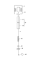
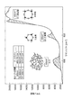
- FIG. 2 is a conceptual diagram showing an example of the configuration of a drawing apparatus for manufacturing the optical fiber 1.
- the drawing apparatus includes a drawing furnace 10, a heating furnace 20, a forced cooling unit 20, a die 40, a UV furnace 50, and a winding bobbin 60.
- the heating furnace 20 includes an upper heating furnace 21 and a lower heating furnace 22.
- the optical fiber preform 2 is drawn by this drawing device, and the optical fiber 1 is manufactured.
- the manufacturing method of the optical fiber 1 is as follows. First, a core and an optical clad in which light is guided by a vapor phase glass synthesis method such as VAD, OVD, MCVD, and PCVD are prepared, and a VAD, OVD, APVD, a rod-in collapse method, or the like is provided around the optical clad. Thus, the jacket layer is formed to form the optical fiber preform 2.
- the optical fiber preform 2 thus prepared is held by a drawing tower, and the lower end portion is heated to a temperature equal to or higher than the working point in the drawing furnace 10 to be melted and stretched by its own weight.
- Elongating and falling glass is appropriately drawn and spun, and the outer diameter of the spun optical fiber is controlled, and the optical fiber is formed through a die 40 for attaching a resin, a UV furnace 50 for curing the resin, and the like.
- the optical fiber is wound up by a winding bobbin 60.
- a resin coating layer is provided on the outer periphery of the jacket 13.
- the resin coating layer has a two-layer structure, and includes a primary coating layer that prevents external force from being directly transmitted to the glass fiber, and a secondary coating layer that prevents damage.
- the dies 40 for applying the respective resin layers may be arranged in series in the spinning process. Moreover, you may apply
- the surface temperature of the glass fiber when entering the die 40 is controlled to a suitable temperature. be able to. It is desirable that the Reynolds number of the gas flowing in the apparatus for controlling the cooling rate is low because vibration due to generation of turbulent flow applied to the spun fiber is reduced. Further, by controlling the cooling rate of the glass fiber, it is possible to reduce the Rayleigh scattering and obtain an optical fiber having a low transmission loss.
- the UV furnace 40 for curing the resin can appropriately control the curing speed of the resin by feedback controlling the temperature inside the furnace in addition to the intensity of the UV light.
- a magnetron or an ultraviolet LED is preferably used.
- an ultraviolet LED since the light source itself does not generate heat, a mechanism for supplying warm air is provided separately so that the temperature in the furnace becomes appropriate.
- the degree of decrease in the UV light power during drawing since the component desorbed from the resin adheres to the inner surface of the core tube of the UV furnace 40 and the power of the UV light reaching the coating layer changes during drawing, the degree of decrease in the UV light power during drawing in advance.
- the UV light power may be adjusted by the drawing time so that the power of the UV light applied to the coating layer is constant. Further, the UV light leaking from the core tube may be monitored and controlled so that the power of the UV light applied to the coating layer is constant. Thereby, the breaking strength of the optical fiber that is uniform over the entire length of the optical fiber can be obtained.
- the thickness of the secondary coating layer is preferably set appropriately so as to maintain the damage resistance.
- the thickness of the secondary coating layer is preferably 10 ⁇ m or more, more preferably 20 ⁇ m or more.
- the optical fiber 1 manufactured in this way and wound up by a winding bobbin is colored in a coating layer as necessary and used as a final product such as an optical cable or an optical cord.
- the optical fiber 1 spun in the drawing furnace 10 enters the die 40 through the heating furnace 20 after exiting the drawing furnace 10.
- the spun optical fiber is heated at a temperature of 1400 from a portion having a diameter of 500% or less of the final outer diameter (generally 125 ⁇ m) of the optical fiber 1 at the lower end of the molten optical fiber preform 2.
- the part until it becomes ° C is continuously cooled at a cooling rate of 1000 ° C / s or more and 10,000 ° C / s or less.
- the heating furnace 20 is provided below the drawing furnace 10 and below the surface where the spun optical fiber 1 substantially exits the drawing furnace 10 (drawing furnace outlet).
- the distance from the exit of the drawing furnace 10 to the entrance of the heating furnace 20 is 1 m or less. It is desirable to have a heat insulation structure that prevents a decrease in the temperature of the spun optical fiber 1 from the exit of the drawing furnace 10 to the entrance of the heating furnace 20.
- the temperature of the optical fiber 1 when entering the heating furnace 20 is preferably 1000 ° C. or higher, more preferably 1400 ° C. or higher.
- the length of the heating furnace 20 can be shortened until the temperature rises to a temperature at which the optical fiber 1 is reheated in the heating furnace 20 and the structure can be substantially relaxed (generally, a temperature above the glass transition point).
- the relaxation time can be taken longer.
- the length L of the heating furnace 20 is set so that L / V is 0.05 s or more when the drawing speed is V.
- the heating furnace 20 is preferably composed of a plurality of furnaces 21 and 22. Thereby, the cooling rate of the optical fiber 1 can be changed in the longitudinal direction. By manufacturing an optical fiber using such a heating furnace 20, an optical fiber with reduced Rayleigh scattering can be obtained.
- the drawing speed V is preferably 30 m / s or more.
- the length L of the heating furnace needs to be 6 m.
- the length L of the heating furnace 20 is lengthened and workability is lowered, or the total height of the drawing apparatus needs to be increased, which increases the amount of capital investment.
- Shortening L is important in establishing economical manufacturing conditions.
- FIG. 3 is a graph showing the Raman spectrum of silica glass. Pull the baseline 525 cm -1 or more 475cm -1 following wavenumber range, calculates the D1 peak area sandwiched between the baseline and the spectrum. Further, drawing a base line on the wave number range of 880 cm -1 or more 740 cm -1 or less, to calculate the 800 cm -1 peak area sandwiched between the baseline and the spectrum. The ratio of the D1 peak area to the 800 cm ⁇ 1 peak area and the IR method (D.-L. Kim, et al., J. Non-Cryst. Solids, Vol. 286, pp.
- the fictive temperature of silica glass can be determined using the relationship with the fictive temperature measured in advance.
- the fictive temperature of the optical fiber can be evaluated by measuring the microscopic Raman scattering spectrum of silica glass at each site constituting the optical fiber and using the above method.
- the slow cooling in the optical fiber manufacturing method of this embodiment will be described.
- one end of an optical fiber preform 2 is heated and melted in a drawing furnace 10 to spin the optical fiber 1 and the optical fiber 1 obtained in the spinning process is drawn.
- ⁇ (T) Aexp (Ea / k B T) (1)
- A a constant
- Ea the activation energy
- k B the Boltzmann constant
- Tf (n) The fictive temperature of the core at a certain position n in the spinning process and the slow cooling process
- Tf (n + 1) the fictive temperature of the core after the unit time ⁇ t has elapsed
- Tf (n + 1) the fictive temperature of the core after the unit time ⁇ t has elapsed
- Tf (n + 1) the fictive temperature of the core after the unit time ⁇ t has elapsed
- Tf (n + 1) the target temperature at the position n.
- FIG. 4 shows the relationship of the recurrence formula.
- Tf (n + 1) T (n) + (Tf (n) ⁇ T (n)) exp ( ⁇ t / ⁇ (T (n))) (2)
- the temperature of the heating furnace 20 is set so that the virtual temperature Tf (0) of the optical fiber is effectively lowered.
- the temperature of the heating furnace 20 is set so as to be a difference of ⁇ 100 ° C. or less (preferably ⁇ 50 ° C. or less) with respect to the target temperature T (n) that minimizes 1).
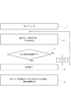
- FIG. 5 is a flowchart showing a procedure for obtaining the target temperature T (n) of the optical fiber at each position.
- ⁇ (T) is small, so the virtual temperature Tf (0) and the actual temperature T are substantially equal.
- a target temperature T (0) that minimizes the virtual temperature Tf (1) of the core after the unit time ⁇ t has elapsed is obtained numerically or analytically (STEP 2).
- a target temperature T (n) at which the virtual temperature Tf (n + 1) of the core after the lapse of the unit time ⁇ t is lowest is obtained with respect to the virtual temperature Tf (n) of the core at a certain position n. .
- Such a process is started from a first position where the glass outer diameter of the optical fiber is a predetermined outer diameter, and is ended at a second position where the target temperature T (n) is equal to or lower than the predetermined temperature (STEP 3) (STEP 4).
- the temperature of the heating furnace 20 is set so as to have a difference of ⁇ 100 ° C. or less (preferably ⁇ 50 ° C. or less) with respect to the target temperature T (n) (STEP 5).
- the first position where the processing is started is a position where the glass outer diameter of the optical fiber is smaller than 500% of the final outer diameter, and preferably a position where the glass outer diameter of the optical fiber is smaller than 200% of the final outer diameter. . Thereby, slow cooling can be performed without impairing the controllability of the outer diameter of the optical fiber.
- the second position where the processing is finished is a position where the target temperature of the optical fiber is 1400 ° C. Thereby, the fictive temperature can be lowered sufficiently.
- the target temperature By obtaining the target temperature in this way, it is possible to obtain a temperature history that the optical fiber should experience when the virtual temperature is most efficiently reduced in a certain material, and it is possible to obtain an optical fiber with reduced Rayleigh scattering. Therefore, the slow cooling time required to obtain a predetermined transmission loss can be shortened, and the length of the slow cooling furnace can be shortened.
- a turbulent flow occurs at a position where the temperature changes suddenly, and the cooling efficiency of the temperature applied to the optical fiber changes randomly.
- the outer diameter of the optical fiber varies. Therefore, it is desirable that the average temperature in the cross-sectional direction of the optical fiber is 1650 ° C. or lower at the position where the optical fiber is first brought into contact with the gas having a temperature of 500 ° C. or lower after being spun by the drawing furnace 10. More preferably, it is 1550 degrees C or less. By doing so, it is possible to reduce the fictive temperature while preventing fluctuations in the wire diameter to about ⁇ 0.2 ⁇ m or less at 3 ⁇ .
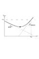
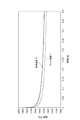
- FIG. 6 is a graph showing the derivation result of an appropriate slow cooling heat history in the case of a general-purpose single mode optical fiber.
- FIG. 6 with an appropriate slow cooling history, when the optical fiber temperature is high, the optical fiber is rapidly cooled, and as the optical fiber temperature decreases, the cooling rate of the optical fiber is decreased. Useful for reduction.
- the concentration of GeO 2 added to the core is about 3.0 mol% to 4.0 mol%.
- the predicted variation of the virtual temperature is within ⁇ 50 ° C.
- ⁇ (T) also varies with additional additives to the core and the composition of the jacket.
- the virtual temperature of the optical fiber can be reduced more efficiently as the temperature of the optical fiber is set to be closer to the derived target temperature history.
- the virtual temperature of the optical fiber is efficiently reduced by drawing so that the actual temperature difference with respect to the derived target temperature history is ⁇ 100 ° C. or less in a region of 70% or more in the region being drawn. Can be reduced. More preferably, the temperature difference is ⁇ 50 ° C. or less.
- an average cooling rate is obtained in each of a temperature range of 1700 ° C. or higher and a temperature range of 1400 ° C. or higher and 1600 ° C. or lower, and control is performed so that the optical fiber temperature is cooled at this average cooling rate.
- the average cooling rate in the region where the optical fiber temperature is 1700 ° C. or higher is 10,000 ° C./s
- the average cooling rate in the region where the optical fiber temperature is 1400 ° C. or higher and 1650 ° C. or lower is 5000 ° C./s. Or less (more preferably 3000 ° C. or less).
- the time dependence of this appropriate heat history is constant irrespective of the linear velocity, the length and installation position of a heating furnace required should just be corrected according to a linear velocity.
- Entry temperature to the heating furnace 20 is desirably 1400 ° C. or higher. Thereby, it can prevent that the temperature of an optical fiber falls too much and a relaxation constant becomes large. Moreover, it is desirable that the temperature of entry into the heating furnace 20 is 1650 ° C. or lower. Thereby, the temperature at the temperature change point can be made sufficiently small, and the wire diameter fluctuation can be suppressed to 0.15 ⁇ m or less.
- the fictive temperature of the optical fiber can be reduced to 1560 ° C. or less, and the transmission loss at a wavelength of 1.55 ⁇ m is 0.182 dB. / Km or less.
- a slow cooling region region of ⁇ 100 ° C. or less with respect to the target temperature
- the length of the slow cooling heating furnace is 8 m or less, more preferably 5 m or less, and further preferably 2 m or less.
- the temperature in the heating furnace 20 be a cooling rate of 5000 ° C./s or less, and it is desirable that the temperature of the optical fiber gradually decreases as it proceeds to the lower part.
- an upward air flow is generated in the heating furnace 20 due to the chimney effect, so that a gas near room temperature flows into the heating furnace 20 from the lower part of the heating furnace 20 and is substantially light in the heating furnace 20.
- the gas temperature with which the fiber contacts decreases.
- the temperature of the gas that flows in rises and approaches the inner peripheral surface temperature of the heating furnace 20.
- the cooling effect due to the updraft can be compensated, so that an appropriate slow cooling temperature history is obtained. Can be obtained.
- the inner peripheral surface temperature of the lower heating furnace 21 is higher by 50 ° C. or more than the inner peripheral surface temperature of the upper heating furnace 21.
- the inner peripheral surface temperature of the lower heating furnace 22 ⁇ 100 ° C. or less (more preferably ⁇ 50 ° C. or less) with respect to the fictive temperature of the spun optical fiber, it is possible to easily approximate the ideal slow cooling heat history. Can do.
- an optical fiber in which the transmission loss at a wavelength of 1550 nm is reduced to 0.182 dB / km or less (preferably 0.179 dB / km or less) can be obtained economically
- an optical fiber in which the increase in transmission loss due to the OH group at a wavelength of 1383 nm is reduced to 0.02 dB / km or less can be obtained economically.
- the hydrogen resistance characteristics of the optical fiber may deteriorate. Therefore, by further providing a deuterium treatment step in which the optical fiber is exposed to a deuterium gas atmosphere, it is possible to obtain a low-loss optical fiber while preventing an increase in transmission loss due to hydrogen diffusion.
Landscapes
- Chemical & Material Sciences (AREA)
- Engineering & Computer Science (AREA)
- Life Sciences & Earth Sciences (AREA)
- Geochemistry & Mineralogy (AREA)
- General Life Sciences & Earth Sciences (AREA)
- Materials Engineering (AREA)
- Organic Chemistry (AREA)
- Physics & Mathematics (AREA)
- Thermal Sciences (AREA)
- Manufacturing & Machinery (AREA)
- Chemical Kinetics & Catalysis (AREA)
- General Chemical & Material Sciences (AREA)
- General Physics & Mathematics (AREA)
- Optics & Photonics (AREA)
- Manufacture, Treatment Of Glass Fibers (AREA)
Priority Applications (4)
| Application Number | Priority Date | Filing Date | Title |
|---|---|---|---|
| EP13838982.0A EP2899168B1 (de) | 2012-09-24 | 2013-09-24 | Glasfaserherstellungsverfahren |
| DK13838982.0T DK2899168T3 (en) | 2012-09-24 | 2013-09-24 | PROCEDURE FOR MANUFACTURING OPTICAL FIBERS |
| CN201380049666.XA CN104661975B (zh) | 2012-09-24 | 2013-09-24 | 光纤制造方法 |
| US14/430,336 US20150251945A1 (en) | 2012-09-24 | 2013-09-24 | Optical fiber fabrication method |
Applications Claiming Priority (2)
| Application Number | Priority Date | Filing Date | Title |
|---|---|---|---|
| JP2012209504A JP6048031B2 (ja) | 2012-09-24 | 2012-09-24 | 光ファイバ製造方法 |
| JP2012-209504 | 2012-09-24 |
Publications (1)
| Publication Number | Publication Date |
|---|---|
| WO2014046274A1 true WO2014046274A1 (ja) | 2014-03-27 |
Family
ID=50341573
Family Applications (1)
| Application Number | Title | Priority Date | Filing Date |
|---|---|---|---|
| PCT/JP2013/075611 WO2014046274A1 (ja) | 2012-09-24 | 2013-09-24 | 光ファイバの製造方法 |
Country Status (6)
| Country | Link |
|---|---|
| US (1) | US20150251945A1 (de) |
| EP (1) | EP2899168B1 (de) |
| JP (1) | JP6048031B2 (de) |
| CN (1) | CN104661975B (de) |
| DK (1) | DK2899168T3 (de) |
| WO (1) | WO2014046274A1 (de) |
Cited By (3)
| Publication number | Priority date | Publication date | Assignee | Title |
|---|---|---|---|---|
| WO2016089733A3 (en) * | 2014-12-02 | 2016-07-28 | Corning Incorporated | Low attenuation optical fiber |
| CN107817552A (zh) * | 2016-09-13 | 2018-03-20 | 住友电气工业株式会社 | 光纤和着色光纤 |
| EP4253336A1 (de) | 2022-03-31 | 2023-10-04 | Sterlite Technologies Limited | Biegen von glasfasern in einem türm |
Families Citing this family (16)
| Publication number | Priority date | Publication date | Assignee | Title |
|---|---|---|---|---|
| JP6303744B2 (ja) * | 2014-04-11 | 2018-04-04 | 住友電気工業株式会社 | 光ファイバの製造装置および光ファイバの製造方法 |
| JP6545568B2 (ja) | 2015-08-11 | 2019-07-17 | 株式会社フジクラ | 光ファイバ素線の製造方法 |
| US10221089B2 (en) * | 2015-09-10 | 2019-03-05 | Corning Incorporated | Optical fiber with low fictive temperature |
| JP6243887B2 (ja) * | 2015-10-29 | 2017-12-06 | 株式会社フジクラ | 光ファイバの製造方法 |
| JP2017081796A (ja) * | 2015-10-29 | 2017-05-18 | 株式会社フジクラ | 光ファイバの製造方法 |
| EP3368489B1 (de) * | 2015-10-30 | 2023-01-18 | Corning Incorporated | Verfahren zur herstellung einer glasfaser |
| CN108698905A (zh) * | 2016-02-24 | 2018-10-23 | 康宁股份有限公司 | 加工光纤的方法和系统 |
| JP6254628B2 (ja) * | 2016-03-16 | 2017-12-27 | 株式会社フジクラ | 光ファイバの製造方法 |
| JP6340390B2 (ja) * | 2016-08-30 | 2018-06-06 | 株式会社フジクラ | 光ファイバの製造方法 |
| JP6397109B2 (ja) * | 2017-11-02 | 2018-09-26 | 株式会社フジクラ | 光ファイバの製造方法 |
| JP2019120894A (ja) * | 2018-01-11 | 2019-07-22 | 住友電気工業株式会社 | 光ファイバ、光ファイバ心線および光伝送システム |
| EP4023619A4 (de) * | 2019-08-30 | 2023-12-06 | Furukawa Electric Co., Ltd. | Glasfaser |
| WO2021163130A1 (en) * | 2020-02-14 | 2021-08-19 | Corning Incorporated | Systems and methods for processing optical fiber |
| CN115515909A (zh) | 2020-05-08 | 2022-12-23 | 康宁股份有限公司 | 具有卤素掺杂纤芯的光纤的缓慢冷却 |
| CN113340504B (zh) * | 2021-07-13 | 2022-03-01 | 中国工程物理研究院激光聚变研究中心 | 一种从熔石英假想温度分布获取残余应力分布的方法 |
| CN113716862B (zh) * | 2021-09-01 | 2023-03-21 | 中天科技光纤有限公司 | 光纤的制备方法及其装置 |
Citations (5)
| Publication number | Priority date | Publication date | Assignee | Title |
|---|---|---|---|---|
| JP2000335934A (ja) * | 1999-05-27 | 2000-12-05 | Sumitomo Electric Ind Ltd | 光ファイバの製造装置及び製造方法 |
| JP2001114525A (ja) * | 1999-10-12 | 2001-04-24 | Sumitomo Electric Ind Ltd | 光ファイバの製造方法及び製造装置 |
| JP2006030655A (ja) * | 2004-07-16 | 2006-02-02 | Furukawa Electric Co Ltd:The | 光ファイバとその評価方法および製造方法 |
| JP2006058494A (ja) | 2004-08-18 | 2006-03-02 | Fujikura Ltd | 光ファイバ素線及びその製造方法 |
| JP2010168247A (ja) * | 2009-01-22 | 2010-08-05 | Sumitomo Electric Ind Ltd | 光ファイバの製造方法及び光ファイバの製造装置 |
Family Cites Families (12)
| Publication number | Priority date | Publication date | Assignee | Title |
|---|---|---|---|---|
| JPH0459631A (ja) * | 1990-06-27 | 1992-02-26 | Sumitomo Electric Ind Ltd | 光ファイバの線引方法 |
| JP3362329B2 (ja) * | 1995-06-26 | 2003-01-07 | 住友電気工業株式会社 | 光ファイバ接続部材とその製造方法及び接続方法 |
| AU773667B2 (en) * | 1999-05-27 | 2004-06-03 | Sumitomo Electric Industries, Ltd. | Production device and method for optical fiber |
| WO2000073223A1 (fr) * | 1999-05-27 | 2000-12-07 | Sumitomo Electric Industries, Ltd. | Dispositif et procede de production pour fibre optique |
| CA2355819A1 (en) * | 2000-08-28 | 2002-02-28 | Sumitomo Electric Industries, Ltd. | Optical fiber, method of making optical fiber preform, and method of making optical fiber |
| US20040031291A1 (en) * | 2001-01-31 | 2004-02-19 | Takahiro Hamada | Drawing method for optical fiber |
| US20020178762A1 (en) * | 2001-06-01 | 2002-12-05 | Foster John D. | Methods and apparatus for forming and controlling the diameter of drawn optical glass fiber |
| JP2003114347A (ja) * | 2001-07-30 | 2003-04-18 | Furukawa Electric Co Ltd:The | シングルモード光ファイバ、その製造方法および製造装置 |
| US6803335B2 (en) * | 2001-08-03 | 2004-10-12 | The University Of Southampton | Gallium lanthanum sulfide glasses and optical waveguides and devices using such glasses |
| US20030200772A1 (en) * | 2002-04-30 | 2003-10-30 | Foster John D. | Methods and apparatus for forming optical fiber |
| US20050259932A1 (en) * | 2002-07-10 | 2005-11-24 | Katsuya Nagayama | Optical fiber and a method for manufacturing same |
| JP4558368B2 (ja) * | 2004-04-09 | 2010-10-06 | 古河電気工業株式会社 | 光ファイバの製造方法 |
-
2012
- 2012-09-24 JP JP2012209504A patent/JP6048031B2/ja active Active
-
2013
- 2013-09-24 DK DK13838982.0T patent/DK2899168T3/en active
- 2013-09-24 CN CN201380049666.XA patent/CN104661975B/zh active Active
- 2013-09-24 EP EP13838982.0A patent/EP2899168B1/de active Active
- 2013-09-24 WO PCT/JP2013/075611 patent/WO2014046274A1/ja active Application Filing
- 2013-09-24 US US14/430,336 patent/US20150251945A1/en not_active Abandoned
Patent Citations (5)
| Publication number | Priority date | Publication date | Assignee | Title |
|---|---|---|---|---|
| JP2000335934A (ja) * | 1999-05-27 | 2000-12-05 | Sumitomo Electric Ind Ltd | 光ファイバの製造装置及び製造方法 |
| JP2001114525A (ja) * | 1999-10-12 | 2001-04-24 | Sumitomo Electric Ind Ltd | 光ファイバの製造方法及び製造装置 |
| JP2006030655A (ja) * | 2004-07-16 | 2006-02-02 | Furukawa Electric Co Ltd:The | 光ファイバとその評価方法および製造方法 |
| JP2006058494A (ja) | 2004-08-18 | 2006-03-02 | Fujikura Ltd | 光ファイバ素線及びその製造方法 |
| JP2010168247A (ja) * | 2009-01-22 | 2010-08-05 | Sumitomo Electric Ind Ltd | 光ファイバの製造方法及び光ファイバの製造装置 |
Non-Patent Citations (5)
| Title |
|---|
| D.-L. KIM ET AL., J. NON-CRYST. SOLIDS, vol. 286, 2001, pages 136 - 138 |
| IEICE TECHNICAL REPORT OFT 2007-19, August 2007 (2007-08-01) |
| K. SAITO ET AL., J. AM. CERAM. SOC., vol. 89, no. 1, 2006, pages 65 - 69 |
| S. SAKAGUCHI ET AL., APPLIED OPTICS, vol. 37, no. 33, 1998, pages 7708 - 7711 |
| See also references of EP2899168A4 |
Cited By (4)
| Publication number | Priority date | Publication date | Assignee | Title |
|---|---|---|---|---|
| WO2016089733A3 (en) * | 2014-12-02 | 2016-07-28 | Corning Incorporated | Low attenuation optical fiber |
| CN107817552A (zh) * | 2016-09-13 | 2018-03-20 | 住友电气工业株式会社 | 光纤和着色光纤 |
| JP2018045028A (ja) * | 2016-09-13 | 2018-03-22 | 住友電気工業株式会社 | 光ファイバおよび光ファイバ心線 |
| EP4253336A1 (de) | 2022-03-31 | 2023-10-04 | Sterlite Technologies Limited | Biegen von glasfasern in einem türm |
Also Published As
| Publication number | Publication date |
|---|---|
| CN104661975A (zh) | 2015-05-27 |
| US20150251945A1 (en) | 2015-09-10 |
| JP2014062021A (ja) | 2014-04-10 |
| CN104661975B (zh) | 2017-09-19 |
| EP2899168B1 (de) | 2018-01-31 |
| EP2899168A1 (de) | 2015-07-29 |
| JP6048031B2 (ja) | 2016-12-21 |
| DK2899168T3 (en) | 2018-03-12 |
| EP2899168A4 (de) | 2016-10-12 |
Similar Documents
| Publication | Publication Date | Title |
|---|---|---|
| WO2014046274A1 (ja) | 光ファイバの製造方法 | |
| JP5831189B2 (ja) | 光ファイバおよび光伝送システム | |
| JP6020045B2 (ja) | 光ファイバ | |
| CN109298482A (zh) | 一种低衰减和低弯曲损耗的大有效面积单模光纤 | |
| US20190185365A1 (en) | Method for manufacturing optical fiber | |
| CN107108327B (zh) | 光纤的制造方法 | |
| JPWO2005049516A1 (ja) | 光ファイバ裸線の線引方法、光ファイバ素線の製造方法、光ファイバ素線 | |
| WO2013140688A1 (ja) | 光ファイバの製造方法 | |
| US10710924B2 (en) | Optical fiber production method | |
| CN101097273A (zh) | 宏弯曲不敏感光学纤维 | |
| JP4459720B2 (ja) | 光ファイバ素線の製造方法 | |
| CN110845135A (zh) | 光纤的制造方法 | |
| JP6175467B2 (ja) | 光ファイバ母材製造方法、光ファイバ母材及び光ファイバ | |
| JP2020158349A (ja) | 光ファイバの製造方法 | |
| CN116184561A (zh) | 大芯径光纤及其成型方法 | |
| JP2014001115A (ja) | 光ファイバ製造方法 |
Legal Events
| Date | Code | Title | Description |
|---|---|---|---|
| 121 | Ep: the epo has been informed by wipo that ep was designated in this application |
Ref document number: 13838982 Country of ref document: EP Kind code of ref document: A1 |
|
| WWE | Wipo information: entry into national phase |
Ref document number: 2013838982 Country of ref document: EP |
|
| WWE | Wipo information: entry into national phase |
Ref document number: 14430336 Country of ref document: US |
|
| NENP | Non-entry into the national phase |
Ref country code: DE |