WO2014046196A1 - 固体酸化物形燃料電池用アノード支持体、アノード支持型ハーフセル及びアノード支持型固体酸化物形燃料電池単セル並びにアノード支持型ハーフセルの製造方法 - Google Patents
固体酸化物形燃料電池用アノード支持体、アノード支持型ハーフセル及びアノード支持型固体酸化物形燃料電池単セル並びにアノード支持型ハーフセルの製造方法 Download PDFInfo
- Publication number
- WO2014046196A1 WO2014046196A1 PCT/JP2013/075332 JP2013075332W WO2014046196A1 WO 2014046196 A1 WO2014046196 A1 WO 2014046196A1 JP 2013075332 W JP2013075332 W JP 2013075332W WO 2014046196 A1 WO2014046196 A1 WO 2014046196A1
- Authority
- WO
- WIPO (PCT)
- Prior art keywords
- anode
- paper
- porous support
- conductive oxide
- support substrate
- Prior art date
- Legal status (The legal status is an assumption and is not a legal conclusion. Google has not performed a legal analysis and makes no representation as to the accuracy of the status listed.)
- Ceased
Links
Images







Classifications
-
- H—ELECTRICITY
- H01—ELECTRIC ELEMENTS
- H01M—PROCESSES OR MEANS, e.g. BATTERIES, FOR THE DIRECT CONVERSION OF CHEMICAL ENERGY INTO ELECTRICAL ENERGY
- H01M4/00—Electrodes
- H01M4/86—Inert electrodes with catalytic activity, e.g. for fuel cells
- H01M4/88—Processes of manufacture
- H01M4/8875—Methods for shaping the electrode into free-standing bodies, like sheets, films or grids, e.g. moulding, hot-pressing, casting without support, extrusion without support
-
- H—ELECTRICITY
- H01—ELECTRIC ELEMENTS
- H01M—PROCESSES OR MEANS, e.g. BATTERIES, FOR THE DIRECT CONVERSION OF CHEMICAL ENERGY INTO ELECTRICAL ENERGY
- H01M4/00—Electrodes
- H01M4/86—Inert electrodes with catalytic activity, e.g. for fuel cells
- H01M4/8605—Porous electrodes
- H01M4/8621—Porous electrodes containing only metallic or ceramic material, e.g. made by sintering or sputtering
-
- H—ELECTRICITY
- H01—ELECTRIC ELEMENTS
- H01M—PROCESSES OR MEANS, e.g. BATTERIES, FOR THE DIRECT CONVERSION OF CHEMICAL ENERGY INTO ELECTRICAL ENERGY
- H01M4/00—Electrodes
- H01M4/86—Inert electrodes with catalytic activity, e.g. for fuel cells
- H01M4/8647—Inert electrodes with catalytic activity, e.g. for fuel cells consisting of more than one material, e.g. consisting of composites
- H01M4/8652—Inert electrodes with catalytic activity, e.g. for fuel cells consisting of more than one material, e.g. consisting of composites as mixture
-
- H—ELECTRICITY
- H01—ELECTRIC ELEMENTS
- H01M—PROCESSES OR MEANS, e.g. BATTERIES, FOR THE DIRECT CONVERSION OF CHEMICAL ENERGY INTO ELECTRICAL ENERGY
- H01M4/00—Electrodes
- H01M4/86—Inert electrodes with catalytic activity, e.g. for fuel cells
- H01M4/8647—Inert electrodes with catalytic activity, e.g. for fuel cells consisting of more than one material, e.g. consisting of composites
- H01M4/8657—Inert electrodes with catalytic activity, e.g. for fuel cells consisting of more than one material, e.g. consisting of composites layered
-
- H—ELECTRICITY
- H01—ELECTRIC ELEMENTS
- H01M—PROCESSES OR MEANS, e.g. BATTERIES, FOR THE DIRECT CONVERSION OF CHEMICAL ENERGY INTO ELECTRICAL ENERGY
- H01M8/00—Fuel cells; Manufacture thereof
- H01M8/10—Fuel cells with solid electrolytes
- H01M8/12—Fuel cells with solid electrolytes operating at high temperature, e.g. with stabilised ZrO2 electrolyte
- H01M8/1213—Fuel cells with solid electrolytes operating at high temperature, e.g. with stabilised ZrO2 electrolyte characterised by the electrode/electrolyte combination or the supporting material
- H01M8/1226—Fuel cells with solid electrolytes operating at high temperature, e.g. with stabilised ZrO2 electrolyte characterised by the electrode/electrolyte combination or the supporting material characterised by the supporting layer
-
- H—ELECTRICITY
- H01—ELECTRIC ELEMENTS
- H01M—PROCESSES OR MEANS, e.g. BATTERIES, FOR THE DIRECT CONVERSION OF CHEMICAL ENERGY INTO ELECTRICAL ENERGY
- H01M4/00—Electrodes
- H01M4/86—Inert electrodes with catalytic activity, e.g. for fuel cells
- H01M2004/8678—Inert electrodes with catalytic activity, e.g. for fuel cells characterised by the polarity
- H01M2004/8684—Negative electrodes
-
- H—ELECTRICITY
- H01—ELECTRIC ELEMENTS
- H01M—PROCESSES OR MEANS, e.g. BATTERIES, FOR THE DIRECT CONVERSION OF CHEMICAL ENERGY INTO ELECTRICAL ENERGY
- H01M8/00—Fuel cells; Manufacture thereof
- H01M8/10—Fuel cells with solid electrolytes
- H01M8/12—Fuel cells with solid electrolytes operating at high temperature, e.g. with stabilised ZrO2 electrolyte
- H01M2008/1293—Fuel cells with solid oxide electrolytes
-
- Y—GENERAL TAGGING OF NEW TECHNOLOGICAL DEVELOPMENTS; GENERAL TAGGING OF CROSS-SECTIONAL TECHNOLOGIES SPANNING OVER SEVERAL SECTIONS OF THE IPC; TECHNICAL SUBJECTS COVERED BY FORMER USPC CROSS-REFERENCE ART COLLECTIONS [XRACs] AND DIGESTS
- Y02—TECHNOLOGIES OR APPLICATIONS FOR MITIGATION OR ADAPTATION AGAINST CLIMATE CHANGE
- Y02E—REDUCTION OF GREENHOUSE GAS [GHG] EMISSIONS, RELATED TO ENERGY GENERATION, TRANSMISSION OR DISTRIBUTION
- Y02E60/00—Enabling technologies; Technologies with a potential or indirect contribution to GHG emissions mitigation
- Y02E60/30—Hydrogen technology
- Y02E60/50—Fuel cells
-
- Y—GENERAL TAGGING OF NEW TECHNOLOGICAL DEVELOPMENTS; GENERAL TAGGING OF CROSS-SECTIONAL TECHNOLOGIES SPANNING OVER SEVERAL SECTIONS OF THE IPC; TECHNICAL SUBJECTS COVERED BY FORMER USPC CROSS-REFERENCE ART COLLECTIONS [XRACs] AND DIGESTS
- Y02—TECHNOLOGIES OR APPLICATIONS FOR MITIGATION OR ADAPTATION AGAINST CLIMATE CHANGE
- Y02P—CLIMATE CHANGE MITIGATION TECHNOLOGIES IN THE PRODUCTION OR PROCESSING OF GOODS
- Y02P70/00—Climate change mitigation technologies in the production process for final industrial or consumer products
- Y02P70/50—Manufacturing or production processes characterised by the final manufactured product
Definitions
- the present invention relates to an anode-supported solid oxide fuel cell. More specifically, the present invention relates to an anode support used in an anode-supported solid oxide fuel cell, an anode-supported half cell including the anode support, and an anode-supported solid oxide fuel cell single cell.
- Solid oxide fuel cells operated at high temperatures (eg, 600-900 ° C) have high power generation efficiency and extremely high fuel diversity, so they are generated by reforming hydrocarbon fuel inside the anode.
- SOFC Solid oxide fuel cells
- DIRSOFC direct internal reforming operation
- a typical structure of the SOFC single cell is a solid electrolyte self-supporting membrane type single cell in which an anode (fuel electrode) is provided on one surface of a dense solid electrolyte support and a cathode (air electrode) is provided on the other surface.
- anode fuel electrode
- a cathode air electrode
- it is effective to reduce the IR loss as much as possible by reducing the thickness of the solid electrolyte.
- the solid electrolyte support type single cell there is a limitation in thinning the solid electrolyte in order to maintain the denseness and mechanical strength of the solid electrolyte membrane.
- an anode support type single cell using an anode as a support instead of the solid electrolyte support type cell, an anode support type single cell using an anode as a support has been proposed (for example, see Patent Document 1).
- the anode-supported unit cell uses the anode as a support to ensure the self-sustainability of the entire unit cell. Therefore, compared to the solid electrolyte-supported unit cell, the solid electrolyte can be made thinner, further reducing IR loss. It is possible to make it.
- an anode formed by compacting and sintering Ni powder and stabilized zirconia powder is a support, but the anode support is rigid with a porosity of about 30%.
- the fuel gas such as hydrogen is not sufficiently permeated and diffused.
- the spatial structure of the anode is not suitable as a hydrocarbon reforming reaction field, generation of thermal stress accompanying reforming reaction (endothermic reaction), and deterioration due to carbon deposition. Is likely to occur.
- a SOFC having a general 40 vol% Ni-60 vol% YSZ (yttria stabilized zirconia) anode support is used, since these problems appear remarkably, long-term durability at a commercial level cannot be expected. It was.
- Patent Document 3 discloses a porous support for an anode support having a high porosity and mechanical strength by using a slurry containing a raw material powder having a predetermined particle size and a binder and adjusted under specific conditions. It is disclosed that a substrate can be manufactured.
- an object of the present invention is to provide an anode support for a solid oxide fuel cell having a high porosity while maintaining sufficient mechanical strength.
- Another object of the present invention is to provide an anode-supported half cell having the anode support, a preferred method for producing the same, and an anode-supported solid oxide fuel cell.
- the present invention relates to the following inventions.
- ⁇ 1> It has a paper-like porous support base formed by molding ion conductive oxide fibers into a nonwoven fabric, and an anode active layer composed of electrode catalyst particles and ion conductive oxide particles, An anode support for a solid oxide fuel cell, wherein at least part of the anode active layer is formed inside the paper-like porous support substrate.
- ⁇ 2> The anode support according to ⁇ 1>, wherein the thickness of the anode active layer formed inside the paper-like porous support substrate is 50% or less of the total thickness of the paper-like porous support substrate.
- ⁇ 3> The anode according to ⁇ 1> or ⁇ 2>, wherein a metal catalyst having a reforming activity for hydrocarbons is dispersed and supported on the surface of an ion conductive oxide fiber constituting the paper-like porous support substrate. Support.
- ⁇ 4> The anode support according to any one of ⁇ 1> to ⁇ 3>, wherein the ion conductive oxide fiber is a stabilized zirconia fiber.
- ⁇ 5> The anode support according to any one of ⁇ 1> to ⁇ 4>, wherein the porosity of the paper-like porous support substrate is 75% by volume or more and 95% by volume or less.
- ⁇ 6> The anode support according to any one of ⁇ 1> to ⁇ 5>, wherein the anode active layer includes electrode catalyst particles and ion conductive oxide particles in a volume ratio of 30:70 to 50:50. .
- An anode-supported half-cell comprising an electrolyte layer on the anode support according to any one of ⁇ 1> to ⁇ 6>.
- ⁇ 8> The anode-supporting half cell according to ⁇ 7>, wherein the electrolyte layer has a thickness in the range of 5 ⁇ m to 50 ⁇ m.
- ⁇ 9> The anode-supported half cell according to ⁇ 7> or ⁇ 8>, wherein the electrolyte layer is made of stabilized zirconia.
- An anode-supported solid oxide fuel cell single cell in which a cathode layer is formed on the electrolyte layer of the anode-supported half cell according to any one of ⁇ 7> to ⁇ 9>.
- a paper-like porous support base formed by molding ion-conductive oxide fibers into a nonwoven fabric including the following steps, and an anode activity in which at least a part thereof is formed inside the paper-like porous support base
- a method for producing an anode-supported half cell comprising a layer and an electrolyte layer formed on the anode active layer.
- Step (1) An anode paste containing an electrode catalyst precursor, ion conductive oxide particles and a solvent is applied to one side of the paper-like porous support substrate, and at least a part of the applied anode paste is applied to the paper.
- Step (2) for soaking into the porous support substrate Step (3) for attaching and temporarily fixing the dense solid electrolyte film before the coated anode paste is dried
- step (1) after the anode paste is applied to the paper-like porous support substrate and dried, the anode paste is applied again on the dried anode paste.
- ⁇ 13> The method for producing an anode-supported half cell according to ⁇ 11> or ⁇ 12>, wherein the porosity of the paper-like porous support substrate is 75% by volume or more and 95% by volume or less.
- ⁇ 14> The dense solid electrolyte film according to any one of ⁇ 11> to ⁇ 13>, wherein the dense solid electrolyte film is made of the same type of ion conductive oxide as the ion conductive oxide fiber constituting the paper-like porous support substrate. Manufacturing method of anode supported half cell.
- ⁇ 15> The method for producing an anode-supported half cell according to any one of ⁇ 11> to ⁇ 14>, wherein the dense solid electrolyte film has a thickness in the range of 5 ⁇ m to 50 ⁇ m.
- the electrode catalyst precursor in the anode paste is electrode catalyst oxide particles, and the weight ratio of the electrode catalyst oxide particles to the ion conductive oxide particles is 46:54 to 66:34 ⁇ 11> to the manufacturing method of the anode support type half cell in any one of ⁇ 15>.
- anode support since it is based on a paper-like porous support base that achieves both high porosity and mechanical strength, it is used for a solid oxide fuel cell having a high porosity while maintaining sufficient mechanical strength.
- anode support and an anode-supported half cell and an anode-supported solid oxide fuel cell unit cell including the anode support.
- the present invention relates to an anode activity comprising a paper-like porous support base formed by molding ion-conductive oxide fibers into paper, electrode catalyst particles, and ion-conductive oxide particles.
- a solid oxide fuel cell (SOFC) anode support (hereinafter referred to as "the present invention"), wherein at least a part of the anode active layer is formed inside the paper-like porous support substrate.
- SOFC solid oxide fuel cell
- the anode support of the present invention is provided with an anode support-type half cell provided with an electrolyte layer, and further provided with a cathode layer on the electrolyte layer to provide an anode-supported solid oxide fuel cell single cell (hereinafter referred to as “anode support-type SOFC single cell”). ").
- the anode support of the present invention has a role as an anode of a fuel cell and a function as a support base for supporting the entire anode-supported SOFC single cell.
- the anode support of the present invention can also be used as an anode support having a hydrocarbon reforming activity by supporting a hydrocarbon reforming catalyst on a paper-like porous support substrate as a constituent element.
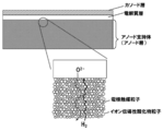
- FIG. 1 is a schematic diagram of a conventional anode-supported SOFC single cell
- FIG. 2 is a schematic diagram of an anode-supported SOFC single cell having the anode support of the present invention.
- the anode support in the conventional anode-supported SOFC single cell has a structure in which electrode catalyst particles such as Ni and ion-conductive oxide particles are pressed and sintered, the porosity is about It is a rigid structure of about 30%.
- Fuel gas such as hydrogen diffuses through the pores and moves inside the anode support, and oxygen ions move inside the anode support via the ion conductive oxide particles.
- the anode material spreads in the direction perpendicular to the electrolyte layer, and the thickness of the three-phase interface that effectively acts as an anode reaction field is limited.
- the anode material beyond this part serves only as a supporting substrate or a current collector, and tends to increase the manufacturing cost of the cell.
- the diffusion of fuel gas is insufficient and the concentration overvoltage tends to increase.
- the spatial structure of the anode is not suitable as a hydrocarbon reforming reaction field, the generation of thermal stress accompanying the reforming reaction (endothermic reaction), and deterioration due to carbon deposition. Is likely to occur.
- the anode support of the present invention is composed of a paper-like porous support substrate that is a porous support substrate having ion-conductive oxide fibers as a skeleton. And at least part of the anode active layer is formed inside the paper-like porous support substrate. Since the paper-like porous support substrate has a much larger pore diameter and porosity than the conventional anode support, the diffusibility of fuel gas in the anode support is greatly improved.
- the anode active layer is composed of electrode catalyst particles and ion conductive oxide particles, and is configured to come into contact with the surface of the ion conductive oxide fiber inside the paper-like porous support substrate.
- the paper-like porous support base is comprised by the ion conductive oxide fiber, and has oxygen ion conductivity as paper-like porous support base itself. Therefore, in the anode support of the present invention, in the anode active layer, the anode material is coated on the ion conductive oxide fiber, and the three-phase interface where the electrode reaction occurs is on the network formed by the ion conductive oxide fiber. Not only three-dimensionally spreading, but also the three-phase interface thickness (thickness from the surface of the ion-conductive oxide) spreading in the network can be kept thin, so the electrode catalyst particles and the ion-conductive oxide particles Compared to a conventional anode support that is a compacted and sintered structure, activation overvoltage and manufacturing costs are reduced.
- the anode support of the present invention is an anode support having hydrocarbon reforming activity by supporting a hydrocarbon reforming catalyst on ion-conductive oxide fibers constituting the paper-like porous support substrate.
- the reforming reaction field has a structure adjacent to the anode active layer, hydrogen generated by the reforming reaction easily diffuses into the anode active layer, and the fuel usage rate is improved.
- the anode support of the present invention has a large pore diameter and porosity due to the paper-like porous support base, and therefore has excellent resistance to thermal stress breakdown accompanying the reforming reaction. Even if carbon is deposited as a side reaction of the reaction, there is an advantage that it is possible to avoid completely closing the void.
- the paper-like porous support substrate is a porous support substrate having ion-conducting oxide fibers as a skeleton, produced by a papermaking technique capable of micro spatial control.
- the paper-like porous support base becomes a skeleton of the anode support, and the ion-conductive oxide fibers are formed into a nonwoven fabric (paper-like) and joined so that the ion-conductive oxide fibers are entangled with each other. It is produced by a method according to the wet papermaking method disclosed in Japanese Patent Application Laid-Open No. 2005-89206 and On-paper Synthesis of Silver Nanoparticles for Antibacterial Applications (ISBN: 978-953-307-028-5). can do.
- a predetermined amount of ion-conducting oxide fiber, a binder component, and other components (porosity adjusting agent, dispersant, etc.) as required are placed in a predetermined amount of solvent and dispersed until uniform.
- a predetermined flocculant is sequentially added to the slurry to generate a floc, and the floc is collapsed by applying a hydraulic shear force, and at the same time, dehydrated using a 200 mesh net.
- the obtained sheet-like composite is dried and subjected to predetermined heat treatment and pressure treatment to obtain a non-woven fabric (paper-like) porous support substrate having a uniform thickness. A specific method will be described later in Examples.
- the ion-conductive oxide fibers constituting the paper-like porous support substrate include thermal stability, chemical properties in the anode-supported half-cell manufacturing process and SOFC power generation conditions (for example, 600 to 900 ° C. in a reducing atmosphere).
- SOFC power generation conditions for example, 600 to 900 ° C. in a reducing atmosphere.
- a fiber made of an ion conductive oxide having high mechanical stability can be used.
- the ion conductive oxide constituting the ion conductive oxide fiber examples include a zirconia (ZrO 2 ) -based oxide, a ceria (CeO 2 ) -based oxide, a LaGaO 3 -based oxide, and a BaZrO 3 -based oxide.
- the ion conductive oxide may be a composite oxide or may contain a dopant.
- stabilized zirconia fibers are preferred because they have high chemical stability in a high-temperature reducing atmosphere and sufficient mechanical strength.
- Examples of the stabilized zirconia include yttria stabilized zirconia (YSZ), scandia stabilized zirconia (ScSZ), and calcia stabilized zirconia (CaSZ).
- YSZ yttria stabilized zirconia
- ScSZ scandia stabilized zirconia
- CaSZ calcia stabilized zirconia
- YSZ yttria-stabilized zirconia
- ScSZ Scandia-stabilized zirconia having higher ion conductivity is also suitable.
- the ion conductive oxide constituting the ion conductive oxide fiber it is preferable to use an ion conductive oxide of the same type as the solid electrolyte used in the anode-supported SOFC of the present invention described later.
- the same kind of ion conductive oxide means that the base ion conductive oxide is the same, and the kind of dopant and the doping amount are not limited.
- a dopant is yttria (Y 2 O 3 ) or scandia (Sc 2 O 3 ). Therefore, when the solid electrolyte is a stabilized zirconia system such as YSZ or ScSZ, it is preferable to use YSZ or ScSZ as the ion conductive oxide fiber.
- the ion conductive oxide fibers constituting the paper-like porous support base are bonded to each other by a binder component.
- the binder component has sufficient chemical stability in the use conditions of SOFC and the manufacturing process of the anode support and the manufacturing process of the anode-supporting half cell and single cell described later, and is an ion conductive oxide fiber.
- Any known inorganic binder can be used as long as it can bind to a sufficient mechanical strength.
- the inorganic binder includes the ion conductive oxide fiber constituting the paper-like porous support substrate.
- the same kind of ion conductive oxide is preferable.
- an inorganic binder as an ion conductive oxide of the same type as the ion conductive oxide fiber constituting the paper-like porous support substrate, chemical / mechanical matching is enhanced and deterioration is suppressed. Can do.
- the same kind of ion conductive oxide has the same meaning as described above.
- Preferable specific examples of the ion conductive oxide fiber and the binder include YSZ for the ion conductive oxide fiber and YSZ or ScSZ for the inorganic binder.
- a binder containing CeO 2 may be used.
- CeO 2 can bind the ion conductive oxide fiber so as to have sufficient mechanical strength as a binder. Furthermore, since it acts as a co-catalyst for the hydrocarbon reforming catalyst, there is a possibility that the hydrocarbon reforming activity of the anode support of the present invention can be improved and further the generation of precipitated carbon can be suppressed. .
- the gap formed by the gap between the ion-conductive oxide fibers in the paper-like porous support base communicates so as to express air permeability, and fuel gas (hydrogen, carbon monoxide, methane, etc.) is generated during SOFC power generation. It is determined within the range in which the mechanical strength is maintained in the production of the anode-supported SOFC and in the power generation conditions without suppressing the flow of hydrocarbon gas or the like.
- the porosity of the paper-like porous support substrate is preferably 75% by volume or more and 95% by volume or less. The porosity of the paper-like porous support substrate can be measured by a mercury intrusion method.
- a pressure is applied to allow mercury to enter the pores of the powder sample, a mercury intrusion curve representing the relationship between the pressure applied to the mercury and the amount of mercury intrusion is obtained, and based on the mercury intrusion curve. , Pore distribution curve, pore volume, specific surface area and the like.
- the measurement by a mercury intrusion method can be performed with a mercury porosimeter.
- the average pore diameter (first mode diameter) obtained from the mercury intrusion method is preferably 10 to 200 ⁇ m.
- the length and thickness of the ion conductive oxide fiber may be within the range in which a paper-like porous support substrate can be formed. Usually, the total length is 30 ⁇ m to 6 mm, preferably 50 ⁇ m to 3 mm, and the diameter is 5 to 20 ⁇ m. The length and thickness of the ion conductive oxide fiber can be confirmed with a scanning electron microscope (SEM).
- the surface shape of the ion conductive oxide fiber is appropriately selected according to the purpose.
- the surface of the ion-conductive oxide fiber is rough in that the bondability between the ion-conductive oxide fibers can be further improved, and the mechanical strength and ion conductivity of the entire paper-like porous support substrate can be increased. Is preferably smaller.
- the surface of the ion conductive oxide fiber is preferably large in that the contact area with the anode active layer can be increased.
- the hydrocarbon reforming catalyst is supported on the surface of the ion conductive oxide fiber, it is advantageous that the surface of the ion conductive oxide fiber has a large roughness.
- the size and thickness of the paper-like porous support substrate are appropriately determined within the range in which the mechanical strength as the support is maintained, and are not particularly limited, but the thickness is usually 300 ⁇ m or more, preferably 500 ⁇ m or more.
- the anode support of the present invention has a role as an anode of a fuel cell.
- a hydrocarbon fuel is used, an ion conductive oxide constituting a paper-like porous support base is used.
- a metal catalyst hydrocarbon reforming catalyst
- the electrocatalyst metal constituting the anode active layer often has a reforming activity for hydrocarbons.
- the electrocatalyst metal alone may not provide sufficient reforming activity for hydrocarbons as a whole of the anode support.
- the reforming activity is improved as an anode support, and it is suitable for SOFC using hydrocarbon fuel. Can be used.
- the metal catalyst having the reforming activity for the hydrocarbon will be described in detail.
- the metal catalyst having the reforming activity for hydrocarbons (hereinafter sometimes referred to simply as “metal catalyst”) is not particularly limited as long as it has the reforming activity for hydrocarbons.
- Ni, Co, Fe, Ru, Rh, Pt, Pd, and alloys thereof are mentioned in terms of having both heat resistance at a temperature (for example, 600 to 900 ° C.) and catalytic activity.
- These metal species are appropriately selected according to the composition of the source gas, reaction conditions, and the like.
- noble metals such as Pt have sufficient reforming activity and are difficult to generate pyrolytic carbon, so that carbon deposition is likely to occur, for example, low grade biogas (mixture of CH 4 and CO 2 Gas) and biodiesel fuel (BDF), etc., can be suitably used when used for reforming raw material gas containing higher hydrocarbons.
- a metal catalyst is usually produced by reducing a precursor compound (for example, an oxide), but if it has a reforming activity on hydrocarbons, it is not completely reduced to a metal and a part of it is a precursor. It may be in the state of a compound.
- Ni is excellent in reforming catalytic properties, but there is a problem that pyrolytic carbon is likely to be generated.
- a raw material gas containing higher hydrocarbons such as BDF carbon deposition may not be sufficiently suppressed.
- the metal catalyst containing Ni and Mg is superior in reforming catalytic properties and suppression of carbon deposition, and is lower in cost than noble metals, and therefore includes higher hydrocarbons such as BDF, which are likely to cause carbon deposition. Suitable for reforming raw material gas.
- the ratio of Ni to Mg (Ni / Mg) in the metal catalyst containing Ni and Mg is usually 0.25 to 4 (atomic ratio), preferably 0.67 to 1.5 (atomic ratio). . This ratio can be measured using EDX.
- the metal catalyst containing Ni and Mg can be obtained, for example, by reducing a composite oxide (NiMgO) obtained by drying and heat-treating an aqueous solution containing each precursor (nitrate or the like).
- the average particle size of the metal catalyst depends on the production method, the average particle size is usually in the range of 2 nm to 2 ⁇ m, and since the surface area can be increased and the reforming reaction can be promoted, the average particle size is preferably 20 nm or less. is there. On the other hand, in the SOFC operating condition, since it is easy to aggregate when it is 50 nm or less, it is preferably 100 nm to 1 ⁇ m from the balance with the catalytic activity.
- the average particle diameter of the metal catalyst was determined by arbitrarily extracting 100 particles each with a scanning electron microscope (SEM) or transmission electron microscope (TEM) and measuring the particle diameter (diameter) for each. , A value calculated as an average value of 100 particle diameters. When the shape of the metal catalyst is other than a spherical shape, the circumference of the particle in the microscopic image is measured with analysis software, and the diameter when the circumference is the circumference is taken as the particle diameter.
- the amount of the metal catalyst supported is appropriately selected according to the type of the metal catalyst, the composition of the raw material gas, and the like. In the case of a metal catalyst made of only Ni or a metal catalyst containing Ni and Mg, the amount is preferably 0.2 to 20% by weight based on the weight of Ni in terms of the balance between catalytic activity and dispersibility.
- the method for dispersing and supporting the metal catalyst on the surface of the paper-like porous support substrate is not particularly limited. For example, after impregnating the paper-like porous support substrate with a solution containing the metal catalyst precursor, drying and firing And a method of generating a particulate metal catalyst on the surface of the paper-like porous support substrate by reduction treatment or the like.
- a paper-like porous support substrate is made using a slurry in which a precursor of a metal catalyst is added together with an ion conductive oxide fiber and a binder component. And the loading of the metal catalyst may be performed simultaneously.
- the precursor of a metal catalyst should just be converted into a particulate metal catalyst by methods, such as heat processing and a reduction process, Nitrate, carbonate, sulfate, acetate, halide of each metal seed
- the anode active layer functions as a fuel electrode (anode) of an anode-supported SOFC (single cell).
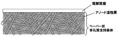
- At least a part of the anode active layer is formed inside the paper-like porous support substrate. Specifically, it may be formed entirely in the paper-like porous support substrate as shown in FIG. 3, or may be formed in a part of the paper-like porous support substrate as shown in FIGS. It may be.
- the anode active layer is in direct contact with the electrolyte layer as shown in FIGS.
- oxygen ions can be supplied to the anode active layer by the ion conductive oxide fibers constituting the paper-like porous support substrate, but the resistance of ion conduction is increased.
- the anode active layer may be composed of two or more layers, and the composition of each may be different.
- the thickness of the anode active layer only needs to have a thickness that functions as a fuel electrode, and is appropriately determined in consideration of the electrode area of the anode and the output required for the SOFC single cell. If the anode active layer is too thick, the flow and diffusion of gas in the paper-like porous support substrate is suppressed, and the gas migration diffusivity derived from the paper-like porous support substrate tends to be reduced. Moreover, when the thickness of the anode active layer is increased, the thickness of the portion having no anode active layer in the paper-like porous support substrate is relatively decreased.
- the hydrocarbon reforming catalyst supported on the portion having no anode active layer is substantially used. Therefore, if the anode active layer is too thick, the reforming catalyst reactivity may be insufficient. Therefore, the thickness of the anode active layer formed inside the paper-like porous support substrate is preferably 50% or less, more preferably 20% or less of the whole paper-like porous support substrate.
- the anode active layer is composed of electrocatalyst metal particles and ion conductive oxide particles, and spreads three-dimensionally on the network formed by the ion conductive oxide fibers in the paper-like porous support substrate.
- the electrocatalyst metal is not particularly limited as long as it has heat resistance at the operating temperature of SOFC (about 600 ° C. to 1000 ° C.) and electrochemical activity as an anode, but Ni, Cu, Fe, Co, Examples thereof include metal particles such as Ag, Pt, Pd, W and Mo, or alloys thereof. Among these, Ni with high electrocatalytic activity is suitable.
- these electrocatalyst metal particles usually exist as precursor oxide particles, and are used after being reduced to metal when used under SOFC operating conditions.
- the ion-conductive oxide particles in the anode active layer become a conduction path of oxygen ions together with the ion-conductive oxide fibers in the paper-like porous support substrate, and the electrode reaction is caused by the ion-conductive oxide particles and the electrocatalyst metal particles.
- the resulting three-phase interface is formed.
- Specific examples of the ion conductive oxide particles include zirconia (ZrO 2 ) -based oxides, ceria (CeO 2 ) -based oxides, and the like.
- ZrO 2 zirconia
- CeO 2 ceria
- Conductive oxide is used.
- the “same kind of ion conductive oxide” has the same meaning as described above.
- ScSZ scandia-stabilized zirconia having higher ion conductivity is preferably used as the ion conductive oxide particles in the anode active layer.
- ScSZ may contain CeO 2 as a dopant in addition to Sc 2 O 3 .
- the ratio of the electrode catalyst particles and the ion conductive oxide particles in the anode active layer may be in a range where the electrode catalyst particles responsible for electronic conductivity in the anode active layer can be sufficiently connected. That is, in the paper-like porous support base according to the present invention, the ion conductive oxide particles do not necessarily have to be connected to each other. This is because it is made of ion-conductive oxide fibers and can be ion-conductive to the solid electrolyte through the paper-like porous support substrate.
- the ratio of the electrode catalyst particles to the ion conductive oxide particles in the anode active layer is preferably a volume ratio of 30:70 to 50:50, more preferably a volume ratio of 35:65 to 45:55.
- the anode active layer may contain a nonionic conductive oxide such as alumina or silica as long as the effects of the present invention are not impaired.
- the anode active layer in the anode support of the present invention can be produced by a method according to a conventionally known SOFC anode production method. That is, an anode paste containing an electrode catalyst precursor, ion-conductive oxide particles and a solvent is applied to a paper-like porous support substrate, or the paper-like porous support substrate is immersed in the anode paste and then dried. It can be formed by firing.
- the electrode catalyst precursor is reduced under the SOFC operating conditions (600 to 900 ° C., reducing atmosphere) to become an electrode catalyst (metal particles).
- the calcination temperature is appropriately determined in consideration of the types of electrode catalyst precursor and ion conductive oxide particles. For example, when the electrode catalyst precursor is nickel oxide (NiO) and the ion conductive oxide particles are stabilized zirconia, the temperature is 1100 to 1500 ° C., preferably 1150 to 1350 ° C.
- the anode active layer may be provided with a current collector for facilitating current collection when the SOFC single cell is used.
- Anode-supporting half-cell of the present invention is obtained by providing an electrolyte layer on the above-described anode support of the present invention.
- the electrolyte layer is a dense film made of an ion conductive oxide, and oxygen ions are conducted through the electrolyte layer during SOFC power generation.
- the ion conductive oxide constituting the electrolyte layer include zirconia (ZrO 2 ) -based oxides and ceria (CeO 2 ) -based oxides.
- ZrO 2 zirconia
- CeO 2 ceria
- ScSZ Zirconia
- ScSZ may contain a dopant (for example, CeO 2 ) other than Sc 2 O 3 as a dopant.
- the electrolyte layer is preferably made of the same type of ion conductive oxide as the anode active layer.
- the “same kind of ion conductive oxide” has the same meaning as described above.
- the thickness of the electrolyte layer is one of the main causes of the internal resistance of the SOFC, and it is preferably as thin as possible so long as the mechanical strength and denseness of the electrolyte layer are maintained.
- the thickness of the electrolyte layer is usually 5 to 300 ⁇ m, preferably 5 to 50 ⁇ m, more preferably 5 to 30 ⁇ m, although it depends on the type of electrolyte.
- the method for forming such an electrolyte layer on the anode support is not particularly limited, and is manufactured by a method according to a conventionally known method for manufacturing an anode-supported cell using a cermet anode active layer obtained by compacting raw material powder as a support. can do.
- an electrolyte slurry is prepared by mixing an electrolyte material (for example, a powder having an average particle size of about 0.1 ⁇ m to 10 ⁇ m) with a solvent together with a predetermined binder, a dispersant and the like.
- the electrolyte slurry can be provided on the anode support by screen-printing on the surface of the anode support of the present invention and then drying and baking at a predetermined firing temperature in the atmosphere.
- the electrolyte layer is densified by sintering the electrolyte material (ion conductive oxide) laminated on the anode support. Since the ion conductive oxide contained in the anode active layer is also sintered and densified in the same manner, the firing temperature is determined in the vicinity of the sintering start temperature of the electrolyte material.
- the electrolyte material is a stabilized zirconia system Is 1300-1400 ° C.
- the firing temperature in a solid electrolyte membrane such as a solid electrolyte self-supporting membrane cell is set to 1400 to 1600 ° C. in order to make the solid electrolyte a denser membrane. That is, at the above 1300 to 1400 ° C., the electrolyte material is insufficiently dense and may cause gas leakage. Therefore, it is necessary to set the thickness of the electrolyte layer to be thick (for example, 100 to 300 ⁇ m).
- method for manufacturing a half cell of the present invention In order to manufacture an anode-supported half cell having a denser and smaller electrolyte layer with high reproducibility, a manufacturing method described below (hereinafter referred to as “method for manufacturing a half cell of the present invention”, or It may be simply referred to as “the production method of the present invention”).
- the half-cell manufacturing method of the present invention includes a paper-like porous support base formed by molding ion-conductive oxide fibers into a paper shape, and an anode at least part of which is formed inside the paper-like porous support base.
- a method of manufacturing an anode-supported half cell having an active layer and an electrolyte layer formed on the anode active layer including the following steps. Step (1): An anode paste containing an electrode catalyst precursor, ion conductive oxide particles and a solvent is applied to one side of the paper-like porous support substrate, and at least a part of the applied anode paste is applied to the paper.
- Step (2) for soaking into the porous support substrate Step (3) for attaching and temporarily fixing the dense solid electrolyte film before the coated anode paste is dried
- an anode paste containing an electrode catalyst precursor, ion-conductive oxide particles and a solvent is applied to one side of the paper-like porous support substrate, and at least a part of the applied anode paste is applied to the paper-like. This is a step of impregnating the porous support substrate.
- the paper-like porous support substrate on which the anode paste is applied is the same as that described for the anode support of the present invention, and the description thereof is omitted. Further, according to the production method of the present invention, an anode active layer can be easily formed even on a paper-like porous support substrate having a porosity of 75% by volume to 95% by volume.
- the electrode catalyst precursor contained in the anode paste may be any material that can be converted into an electrode catalyst under SOFC operating conditions.
- the electrocatalyst metal is not particularly limited as long as it has heat resistance at the operating temperature of SOFC (about 600 ° C. to 1000 ° C.) and electrochemical activity as an anode, but Ni, Cu, Fe, Co, Examples thereof include metal particles such as Ag, Pt, Pd, W and Mo, or alloys thereof. Among these, Ni with high electrocatalytic activity is suitable.
- Electrode catalyst metal oxide particles are usually used as the electrode catalyst precursor.
- the particle size of the electrode catalyst metal oxide particles is preferably 0.05 to 10 ⁇ m, more preferably 0.1 to 3 ⁇ m.
- the electrode catalyst precursor nitrates, carbonates, sulfates, acetates, halides, ammonium salts, oxalates, and the like of the respective metal species may be used instead of the above-described oxide particles.
- ion conductive oxide particles examples include stabilized zirconia (ZrO 2 ) -based oxides and ceria (CeO 2 ) -based oxides as described in the description of the anode active layer described above.
- ZrO 2 stabilized zirconia
- CeO 2 ceria
- the same type of ion conductive oxide as the solid electrolyte is used.
- the “same kind of ion conductive oxide” has the same meaning as described above.
- ScSZ scandia-stabilized zirconia having higher ionic conductivity is preferably used as the ion conductive oxide particles in the anode active layer.
- ScSZ may contain CeO 2 as a dopant in addition to Sc 2 O 3 .
- the particle size of the ion conductive oxide particles is preferably 0.05 to 10 ⁇ m, more preferably 0.1 to 3 ⁇ m.
- the ratio of the electrode catalyst precursor and the ion conductive oxide particles contained in the anode paste is appropriately determined within a range in which sufficient electronic conductivity and ion conductivity can be obtained after the electrode catalyst precursor is converted into the electrode catalyst.
- the electrode catalyst precursor is electrode catalyst oxide particles
- the weight ratio of the electrode catalyst oxide particles to the ion conductive oxide particles is preferably 46:54 to 66:34, more Preferably it is 52:48 to 62:38.
- the viscosity of the anode paste is determined in a range that provides a viscosity suitable for coating.
- the viscosity is adjusted by adjusting the type and amount of the binder and solvent (dispersion medium) used and the solid content concentration in the anode paste.
- the viscosity is adjusted by mixing a solvent (dispersion medium) such as terpineol or terpine oil and ethyl cellulose as a binder with the raw material powder. There are methods.
- the anode paste prepared to an appropriate viscosity is applied to one side of a paper-like porous support substrate.
- one of the features of the production method of the present invention is that at least a part of the coated anode paste is soaked into the paper-like porous support base and a part thereof is left on the surface.
- the anode paste soaked in the paper-like porous support substrate is converted into an anode active layer inside the paper-like porous support substrate by firing in a later step.
- a part of the anode paste remaining on the surface of the paper-like porous support substrate contributes to an improvement in the bonding strength with the dense electrolyte film serving as the electrolyte layer.
- the coating method of the anode paste is not particularly limited, and a conventionally known method can be adopted.
- a screen printing method, a bar coater method, a gravure coater method, a dip coating method, or the like can be employed, and is usually a screen printing method.
- the thickness of the anode active layer to be formed can be controlled by adjusting the viscosity and coating amount of the anode paste.
- the paper-like porous support substrate When the anode active layer is formed entirely inside the paper-like porous support substrate, the paper-like porous support substrate is immersed in the anode paste having a low viscosity, and the anode paste is infiltrated into the inside.
- a method in which an anode paste having a high viscosity is applied to the surface is preferable.
- the anode paste may be diluted with an appropriate solvent.
- the solvent for diluting the anode paste may be any solvent that can uniformly dissolve the components of the anode paste.
- water, alcohols such as ethanol, and solvents such as acetone and ether can be selected depending on the types of components of the anode paste.
- the application (including immersion) of the anode paste may be performed a plurality of times.
- the anode paste applied last may not be dried.
- the paste may be dry.
- the anode paste is coated on the paper-like porous support substrate and dried by an appropriate method, and then the dried anode paste is coated on the dried anode paste. It is preferable to apply the anode paste again.
- the anode paste that has been coated and dried fills the unevenness of the surface of the paper-like porous support substrate and flattens it, and the dense solid electrolyte film in the next step is formed. Affixing is easy.
- a solvent can be removed by heating at about 100 degreeC.
- the drying method may be air drying or vacuum drying.
- Step (2) This step is a step in which a dense solid electrolyte film is pasted and temporarily fixed before the coated anode paste is dried.
- the dense solid electrolyte film is temporarily fixed on the paper-like porous support substrate by applying the dense solid electrolyte film before the anode paste applied in step (1) is dried.
- the coated anode paste has not only the inside of the paper-like porous support substrate, but also a part thereof on the surface, and a solvent (dispersion medium) to such an extent that a dense solid electrolyte film can be pasted and temporarily fixed. It only has to remain and have an appropriate viscosity.
- anode paste in which the ratio of raw material powder, binder and solvent is adjusted so as to have a suitable viscosity in advance, or to apply an anode paste having a low solid content concentration in order to improve coating properties,
- a dense solid electrolyte film may be pasted after drying to such an extent that it does not dry completely.
- the surface of the paper-like porous support substrate according to the present invention has many irregularities, and it is difficult to directly apply the electrolyte film.
- the anode paste is flattened without completely drying the dense electrolyte, Since the film is pasted and temporarily fixed and then fired as a subsequent process, there is an advantage that the electrolyte film and the paper-like porous support substrate can be firmly bonded via the anode active layer.
- the electrolyte becomes too thick or cannot be sufficiently sintered.
- the dense solid electrolyte film serves as an electrolyte layer of an anode-supported half cell.
- the constituent material are the same as those of the ion conductive oxide particles described above, and examples thereof include stabilized zirconia (ZrO 2 ) -based oxides and ceria (CeO 2 ) -based oxides.
- ZrO 2 stabilized zirconia
- CeO 2 ceria
- ScSZ scandia-stabilized zirconia
- ScSZ may contain CeO 2 as a dopant in addition to Sc 2 O 3 .
- the dense solid electrolyte film is made of the same ion conductive oxide as the ion conductive oxide fiber constituting the paper-like porous support base. It is preferable.
- the dense solid electrolyte film may be a thin film as long as no gas leak occurs in terms of reducing IR loss.
- the thickness is preferably 5 ⁇ m to 50 ⁇ m, more preferably 5 ⁇ m to 30 ⁇ m, and even more preferably 5 ⁇ m to 15 ⁇ m.
- This step is a step of firing the paper-like porous support substrate on which the dense solid electrolyte film is temporarily fixed.
- this step by firing the anode active layer, the dense solid electrolyte film temporarily fixed to the paper-like porous support substrate in step (2) and the anode support are firmly bonded.
- the non-dried anode paste for adhering (temporarily fixing) the dense solid electrolyte film and the paper-like porous support substrate is dried. Drying may be performed by a heating process during firing.
- the temperature increase rate is determined within a range in which the dense solid electrolyte film does not peel off or the anode active layer deteriorates due to the difference in thermal expansion coefficient, and is usually 100 to 200 ° C./h.
- the firing temperature is determined in the vicinity of the sintering start temperature of the ion conductive oxide particles contained in the anode active layer in order to suppress excessive sintering of the ion conductive oxide contained in the anode active layer.
- the temperature is 1300 to 1400 ° C.
- a dense solid electrolyte film fired at a high temperature (about 1400 to 1600 ° C.) is used in advance, so that the electrolyte layer remains dense even when fired in the above temperature range. Gas leak does not occur. Therefore, as described above, the thickness of the electrolyte layer can be 5 ⁇ m or more and 30 ⁇ m or less (more preferably, 5 ⁇ m or more and 15 ⁇ m or less).
- Calcination may be performed, for example, in an inert gas atmosphere such as nitrogen gas or argon gas, or in an oxidizing atmosphere in which oxygen is mixed, but is usually performed in an air atmosphere.
- an inert gas atmosphere such as nitrogen gas or argon gas
- an oxidizing atmosphere in which oxygen is mixed but is usually performed in an air atmosphere.
- a step of dispersing and supporting a metal catalyst having a reforming activity for hydrocarbons In the method for producing an anode-supported half cell of the present invention, a metal catalyst having a reforming activity for hydrocarbons on a paper-like porous support substrate. A step of dispersing and supporting (hydrocarbon reforming catalyst) may be included.
- the supporting of the hydrocarbon reforming catalyst may be performed before step (1), between steps (1) to (3), or after step (3), but is usually used before step (1). It is performed on the paper-like porous support substrate or on the half cell formed after the step (3).
- the method for dispersing and supporting the hydrocarbon reforming catalyst on the surface of the paper-like porous support substrate is not particularly limited.
- a solution containing a metal catalyst precursor examples thereof include a method of generating a particulate hydrocarbon reforming catalyst on the surface of a paper-like porous support substrate by drying, firing, reduction treatment or the like.
- the hydrocarbon reforming catalyst is supported by impregnation to the half cell formed after the step (3), the solution containing the excess metal catalyst precursor adhering to the electrolyte layer is removed to prevent a short circuit. It is preferable to do.
- the precursor of the hydrocarbon reforming catalyst is not particularly limited as long as it can be converted into a particulate metal catalyst by a method such as heat treatment or reduction treatment. Nitrate, carbonate, sulfate, acetate, halogen of each metal species. Chemical compounds, ammonium salts, oxalates and the like may be appropriately selected and used.
- a method for preloading the hydrocarbon reforming catalyst on the paper-like porous support substrate in the step used in the step (1) in the method for producing a paper-like porous support substrate by the wet papermaking method, an ion conductive oxidation is performed.
- a slurry to which a precursor of a hydrocarbon reforming catalyst is added together with physical fibers and a binder component papermaking of a paper-like porous support substrate and supporting of a metal catalyst may be performed simultaneously. In this method, dispersibility can be more easily improved, and a paper-like porous support substrate including a uniformly dispersed hydrocarbon reforming catalyst can be obtained.
- Anode-supported SOFC single cell The anode-supported SOFC single cell of the present invention has a cathode layer in the anode-supported half-cell electrolyte layer of the present invention. That is, the cathode layer is formed on the side opposite to the anode support through the electrolyte layer.
- the cathode layer can be formed using a conventionally known material used for SOFC single cells.
- the cathode material is not particularly limited as long as it has electrode activity as a cathode.
- an electrode material containing an oxide such as LaMnO 3 , LaCoO 3 , La 2 NiO 4 , or SmCoO 3 is used. Can do.
- the cathode layer is prepared by, for example, applying a predetermined amount of cathode paste to the electrolyte layer by screen printing of a cathode paste in which a powdered cathode material is mixed with ion conductive oxide particles and dispersed in an appropriate solvent,
- the cathode layer can be formed by firing at about 1100 to 1300 ° C.
- the anode-supported SOFC single cell of the present invention has a much larger pore diameter and porosity (porosity) than the conventional anode-supported SOFC single cell.
- the diffusivity is greatly improved, and the three-phase interface where electrode reaction occurs is not only three-dimensionally spread on the network formed by the ion-conductive oxide fiber, but also the three-phase interface thickness (ion The thickness (from the surface of the conductive oxide) can be kept thin, and thus excellent power generation performance is exhibited.
- Ion conductive oxide fiber / YSZ fiber (a): manufactured by Zirker (product number: ZYBF-2), fiber diameter: 3 to 6 ⁇ m ⁇ YSZ fibers (b): 7mol% Y 2 O 3 - 93mol% ZrO 2 fiber diameter: 10 [mu] m 2.
- Binder ZrO 2 sol (manufactured by Nissan Chemical Industries, product number: Nano-use ZR-30BS, pH 9.8) 3.
- Ionic polymer PDADMAC polydiallyldimethylammonium chloride, Aldrich, Ltd.
- Cationic molecular weight about 3 ⁇ 10 5
- A-PAM anionic polyacrylamide, Kurita, Ltd.
- Anionic molecular weight about 4 ⁇ 10 6
- Ion conductive oxide particles ScSZ (10 mol% Sc 2 O 3 ⁇ 1 mol% CeO 2 —ZrO 2 , average particle size: 0.55 ⁇ m, manufactured by Daiichi Elemental Chemicals, product number: 10Sc1CeZ)
- An anode-supported SOFC single cell for evaluation was produced by the following procedure.
- the pulp ensures the strength of the wet state after paper making, and facilitates the collection of the paper-like porous support substrate before firing from the mesh for filtration.
- the pulp is burned off during the firing of the paper-like porous support substrate, and voids (diffusion paths) are generated.
- the obtained slurry was poured into a commercially available papermaking apparatus (manufactured by Kumagai Riki Kogyo Co., Ltd.), and the suspension mixture was deposited on a metal mesh for filtration (200 mesh) by dehydration. The formed deposit was peeled off from the mesh, pressed at 350 kPa for 3 minutes, and dried at 105 ° C. to obtain a paper-like porous support substrate A (before firing).
- the porosity and pore diameter (mode diameter) of the paper-like porous support substrate A for evaluating physical properties were measured by mercury porosimetry, and as a result, the porosity was 85% and the average pore diameter was 20 ⁇ m.
- anode paste (before viscosity adjustment) was taken in a 100 mL disposable cup, and turpentine oil was added so that the weight ratio of the anode paste and turpentine oil was 75:25 to prepare an anode paste A in which the viscosity was adjusted.
- anode support A An appropriate amount of electrolyte slurry containing ScSZ powder was applied on the surface of the anode support A. Then, it baked at 1300 degreeC for 1 hour, and the anode support type half cell A which has a solid electrolyte layer on the single side
- the porosity and pore diameter (mode diameter) of the paper-like porous support base B were measured by mercury porosimetry, and as a result, the porosity was 80% or more and the pore diameter was 70 to 100 ⁇ m.
- NiO powder was dispersed in ethanol at a weight ratio of 56:44 to ScSZ powder (after reduction: equivalent to a volume ratio of 40:60), dried after ball milling for 24 hours.
- the anode raw material powder was obtained.
- This powder was mixed with ⁇ -terpineol (> 95%, manufactured by Kanto Chemical Co., Ltd.) in which 6 wt% ethyl cellulose (manufactured by Kishida Chemical) was dissolved at a weight ratio of 6: 4, and a three-roll mill (manufactured by EXAKT, Germany) was mixed.
- Anode paste B was prepared using the same.
- the thickness of the anode support (paper-like porous support base) portion in the anode support half cell B was 625 ⁇ m. Further, the anode active layer in the paper-like porous support base B of the half cell B is about 30% by weight with respect to the paper-like porous support base B, and the thickness is less than 16% of the paper-like porous support base B. there were.
- the anode-supported half cell B is immersed in a solution containing 1 mol / L Ni nitrate and Mg nitrate, taken out after 1 hour, wiped off the solid electrolyte film side, and then dried at 105 ° C. for 3 hours.
- an anode-supported half-cell B in which NiMgO precursor fine particles were dispersedly supported on a paper-like porous support substrate was obtained.
- the anode support portion was evaluated by SEM / EDX after the power generation test, it was confirmed that a solid solution of NiO and MgO was formed on the surface of the ion conductive oxide fiber.
- a cathode current paste that was fired for 5 hours to form a paste was printed and fired at 1200 ° C. for 5 hours to produce an electrolyte-supported single cell D.
- the electrode area was 8 mm ⁇ 8 mm.
- a platinum mesh spot-welded with a platinum wire was attached to both electrodes of this single cell so that electrochemical measurement was possible.
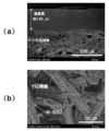
- FIGS. 6 and 7 show SEM images of anode supported half cells A and B.
- FIG. 8 shows an SEM image of a conventional anode-supported single cell C.
- the anode support in the anode-supported single cell C shown in FIGS. 8 (a) and 8 (b) is composed of Ni that is electrode catalyst particles and ScSZ particles that are ion-conductive oxide particles, and the anode support. It can be seen that there are few voids.
- the anode support in anode supported half cells A and B is a YSZ that constitutes a paper-like porous support substrate. It can be seen that the fibers form a network, the pore diameter is large, and the pores are connected.
- the thickness of the solid electrolyte layer was about 140 ⁇ m for the anode supported half cell A, about 23 ⁇ m (film thickness) for the anode supported half cell B, and about 30 ⁇ m for the commercially available anode supported single cell C.
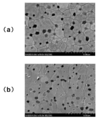
- FIGS. 9A and 9B show SEM images of the surface and cross section of the solid electrolyte layer of the anode-supporting half cell A, respectively. Many pinholes are seen on the surface of the solid electrolyte layer, and it can be seen from the cross-sectional image that there are portions where the pores are connected.
- the solid electrolyte layer of the anode-supporting half cell B some pinholes were confirmed on the surface as shown in FIG. 10 (a), but they were connected to the inside of the electrolyte layer as shown in FIG. 10 (b). It turns out that it does not have a pore.
- an electrolyte layer is produced by applying electrolyte slurry on the surface of a paper-like porous support substrate.
- the paper-like porous support substrate to be coated has a non-uniform surface. Because of its high porosity, it easily penetrates into the electrolyte slurry. Therefore, it is necessary to apply a large amount of electrolyte slurry, and the electrolyte layer is inevitably thick.
- the firing temperature is limited, it is presumed that the denseness of the electrolyte layer to be formed is also lowered.
- the anode-supporting single cell B has a dense electrolyte film attached to the surface of the paper-like porous support substrate, the dense electrolyte film can be formed on the anode support surface.
- FIG. 11 shows a schematic diagram of a SOFC single cell evaluation apparatus.
- a single cell to be measured is set in a single cell evaluation apparatus, and the temperature is raised to 900 ° C. in 4.5 hours. After reaching 900 ° C., dry air (150 mL / min) is supplied to the cathode side, and 3 to the anode side.
- % Humidified hydrogen H 2 flow rate: 150 mL / min
- OCV open circuit voltage
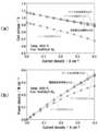
- FIG. 12 shows the power generation characteristics of each cell at 800 ° C. when humidified hydrogen is supplied.
- 12A shows a current-voltage curve (IV curve)
- FIG. 12B shows a current-power curve (IP curve).
- Single cells A at 400 mA ⁇ cm -2 at humidified hydrogen feed, B the output density of the C and D, respectively, 0.269Wcm -2, 0.360Wcm -2, 0.363Wcm -2, 0.352Wcm -2 Met.
- the power density of the anode-supported single cell B was comparable to that of the conventional anode-supported single cell C, and was higher than that of the electrolyte-supported single cell D.
- the anode-supported single cell A exhibited an open circuit voltage that was approximately 150 mV lower than the conventional cell. This is because when an anode-supported half-cell is produced by applying and baking ScSZ electrolyte slurry on paper, it is difficult to densify the electrolyte as shown in FIG. 9B, and gas leakage occurs between the anode and the cathode. This shows that chemical energy loss was caused by direct combustion of fuel gas.
- the anode-supporting single cell B is manufactured by attaching a high-temperature fired ScSZ electrolyte film, so that the electrolyte layer is denser (see FIG. 10B). The remarkable gas leakage in the electrolyte was suppressed, and an open circuit voltage equal to the theoretical electromotive force was obtained, so that high output was shown.
- FIG. 13 shows the voltage loss value of each cell at 800 ° C. when humidified hydrogen is supplied.
- FIG. 13A shows voltage loss (electrode overvoltage) associated with the electrode reaction of the cathode and anode
- FIG. 13B shows loss due to ohmic internal resistance in the cell (IR loss).
- IR loss ohmic internal resistance in the cell
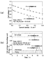
- FIG. 14B shows the result of a constant current test conducted at 200 mA ⁇ cm ⁇ 2 after IV measurement.
- the gas composition is as shown in Table 1.
- air was added to the biogas in order to make the fuel composition thermodynamically outside the carbon deposition region.
- FIG. 14A the developed anode-supported SOFC single cells A and B exhibited good power generation characteristics even when hydrocarbon fuel other than hydrogen was directly supplied. Further, as shown in FIG. 14B, it was confirmed that the voltage stability was also excellent.
Landscapes
- Chemical & Material Sciences (AREA)
- General Chemical & Material Sciences (AREA)
- Chemical Kinetics & Catalysis (AREA)
- Electrochemistry (AREA)
- Engineering & Computer Science (AREA)
- Composite Materials (AREA)
- Manufacturing & Machinery (AREA)
- Life Sciences & Earth Sciences (AREA)
- Sustainable Development (AREA)
- Sustainable Energy (AREA)
- Ceramic Engineering (AREA)
- Fuel Cell (AREA)
- Inert Electrodes (AREA)
Abstract
十分な機械的強度を維持しつつ、高い気孔率を有する固体酸化物形燃料電池用アノード支持体及び該アノード支持型固体酸化物形燃料電池単セルを提供する。イオン伝導性酸化物繊維を不織布状に成形してなるペーパー状多孔質支持基体と、電極触媒粒子及びイオン伝導性酸化物粒子で構成されるアノード活性層とを有し、前記アノード活性層の少なくとも一部が、前記ペーパー状多孔質支持基体の内部に形成されてなる固体酸化物形燃料電池用アノード支持体。該アノード支持体を備えたアノード支持型固体酸化物形燃料電池単セルは、アノード支持体の細孔径、気孔率(空隙率)が非常に大きく、電極反応の起こる三相界面がイオン伝導性酸化物繊維がなすネットワーク上に三次元的に広がっているだけでなく、ネットワーク内に広がる三相界面厚さ(イオン伝導性酸化物表面からの厚さ)を薄く保つことができるため、優れた発電性能を示す。
Description
本発明は、アノード支持型の固体酸化物形燃料電池に関する。より詳しくは、アノード支持型の固体酸化物形燃料電池に用いられるアノード支持体、該アノード支持体を備えたアノード支持型ハーフセル及びアノード支持型固体酸化物形燃料電池単セルに関するものである。
高温(例えば、600~900℃)で作動される固体酸化物形燃料電池(SOFC)は発電効率が高く、また、燃料多様性が極めて高いため、アノード内部で炭化水素燃料を改質して発生した水素を燃料として発電を行う直接内部改質運転(DIRSOFC)が原理的に可能であるという利点がある。そのため、小型(1kW級)でも高い効率が得られると期待されている。
SOFC単セルの代表的な構造として、緻密な固体電解質の支持体の一方の面にアノード(燃料極)、他方の面にカソード(空気極)を設けた固体電解質自立膜型単セルが挙げられる。一方、SOFC単セルの性能を高めるには、固体電解質を薄膜化し、IRロスを極力低減させることが有効である。しかしながら、上記固体電解質支持型単セルでは、固体電解質膜の緻密性や機械的強度を保つため、固体電解質の薄膜化には制限があった。
一方、固体電解質支持型セルに代えて、アノードを支持体としたアノード支持型単セルが提案されている(例えば、特許文献1参照)。アノード支持型単セルは、アノードを支持体として単セル全体の自立性を確保しているため、上記固体電解質支持型単セルと比較して、固体電解質をより薄膜化でき、IRロスをさらに低減させることが可能である。
しかしながら、従来のアノード支持型単セルではNi粉末と安定化ジルコニア粉末を押し固め、焼結させることで成形したアノードが支持体となっているが、アノード支持体は、気孔率30%程度のリジッドな構造であり、十分に水素等の燃料ガスを透過・拡散させ得るような構造を有していなかった。また、直接内部改質を行う場合に、アノードの空間構造が炭化水素の改質反応場として適しておらず、改質反応(吸熱反応)に伴う熱応力の発生、および炭素析出に起因する劣化が生じやすい。例えば、一般的な40vol%Ni-60vol%YSZ(イットリア安定化ジルコニア)アノード支持体を有するSOFCを用いた場合、これらの問題が顕著に現れるため、商用化レベルの長時間耐久性は期待できなかった。
しかしながら、従来のアノード支持型単セルではNi粉末と安定化ジルコニア粉末を押し固め、焼結させることで成形したアノードが支持体となっているが、アノード支持体は、気孔率30%程度のリジッドな構造であり、十分に水素等の燃料ガスを透過・拡散させ得るような構造を有していなかった。また、直接内部改質を行う場合に、アノードの空間構造が炭化水素の改質反応場として適しておらず、改質反応(吸熱反応)に伴う熱応力の発生、および炭素析出に起因する劣化が生じやすい。例えば、一般的な40vol%Ni-60vol%YSZ(イットリア安定化ジルコニア)アノード支持体を有するSOFCを用いた場合、これらの問題が顕著に現れるため、商用化レベルの長時間耐久性は期待できなかった。
アノード支持体における気孔率を増大させる方法として、従来、セルロース等の細孔形成剤を原料粉末と共に混合し、細孔形成剤を焼失させて気孔を形成する方法がとられていた。しかしながら、この方法では十分な気孔率を得るために多量の細孔形成剤を添加すると、原料粉末同士の連結性が低くなり、アノード支持体の機械的強度が著しく低下するという問題があった。
これに対し、特許文献2には、粗大な電融ジルコニア粉末の相互間に微細なジルコニア粉末が入った状態で相互に結合させられた造粒粉末を調製し、その造粒粉末を用いて成形および焼成処理を施す方法が開示されている。この方法によると、電融ジルコニア粉末の焼結が相互の接触部において促進され、多数の連通細孔を有する多孔質体が得られる。
また、特許文献3には、所定の粒径の原料粉末及びバインダーを含み、特定の条件で調整したスラリーを使用することにより、高い気孔率と機械的強度を有するアノード支持体用の多孔質支持基体を製造できることが開示されている。
これに対し、特許文献2には、粗大な電融ジルコニア粉末の相互間に微細なジルコニア粉末が入った状態で相互に結合させられた造粒粉末を調製し、その造粒粉末を用いて成形および焼成処理を施す方法が開示されている。この方法によると、電融ジルコニア粉末の焼結が相互の接触部において促進され、多数の連通細孔を有する多孔質体が得られる。
また、特許文献3には、所定の粒径の原料粉末及びバインダーを含み、特定の条件で調整したスラリーを使用することにより、高い気孔率と機械的強度を有するアノード支持体用の多孔質支持基体を製造できることが開示されている。
しかしながら、特許文献2や特許文献3で開示された方法によっても、粉体原料を使用してアノード支持体を製造した場合には気孔率は50%程度が限界であり、十分な機械的強度を維持しつつ、より気孔率の高いアノード支持体を得ることはできなかった。
かかる状況下、本発明の目的は、十分な機械的強度を維持しつつ、高い気孔率を有する固体酸化物形燃料電池用アノード支持体を提供することである。また、本発明の他の目的は、前記アノード支持体を有するアノード支持型ハーフセル及びその好適な製造方法、並びにアノード支持型固体酸化物形燃料電池を提供することである。
本発明者は、上記課題を解決すべく鋭意研究を重ねた結果、下記の発明が上記目的に合致することを見出し、本発明に至った。
すなわち、本発明は、以下の発明に係るものである。
<1> イオン伝導性酸化物繊維を不織布状に成形してなるペーパー状多孔質支持基体と、電極触媒粒子及びイオン伝導性酸化物粒子で構成されるアノード活性層とを有し、
前記アノード活性層の少なくとも一部が、前記ペーパー状多孔質支持基体の内部に形成されてなる固体酸化物形燃料電池用アノード支持体。
<2> 前記ペーパー状多孔質支持基体の内部に形成されたアノード活性層の厚みが、前記ペーパー状多孔質支持基体全体厚みの50%以下である前記<1>に記載のアノード支持体。
<3> 前記ペーパー状多孔質支持基体を構成するイオン伝導性酸化物繊維の表面に、炭化水素に対する改質活性を有する金属触媒が分散担持された前記<1>または<2>に記載のアノード支持体。
<4> 前記イオン伝導性酸化物繊維が、安定化ジルコニア繊維である前記<1>から<3>のいずれかに記載のアノード支持体。
<5> 前記ペーパー状多孔質支持基体の空隙率が、75体積%以上95体積%以下である前記<1>から<4>のいずれかに記載のアノード支持体。
<6> 前記アノード活性層が、電極触媒粒子とイオン伝導性酸化物粒子とを、体積比30:70~50:50で含む前記<1>から<5>のいずれかに記載のアノード支持体。
<7> 前記<1>から<6>のいずれかに記載のアノード支持体上に電解質層を設けてなるアノード支持型ハーフセル。
<8> 前記電解質層の厚みが、5μm以上50μm以下の範囲内である前記<7>に記載のアノード支持型ハーフセル。
<9> 前記電解質層が、安定化ジルコニアからなる前記<7>または<8>に記載のアノード支持型ハーフセル。
<10> 前記<7>から<9>のいずれかに記載のアノード支持型ハーフセルの電解質層上にカソード層を形成したアノード支持型固体酸化物形燃料電池単セル。
<11> 下記工程を含む、イオン伝導性酸化物繊維を不織布状に成形してなるペーパー状多孔質支持基体と、前記ペーパー状多孔質支持基体の内部にその少なくとも一部が形成されたアノード活性層と、前記アノード活性層上に形成された電解質層とを有するアノード支持型ハーフセルの製造方法。
工程(1):電極触媒前駆体、イオン伝導性酸化物粒子及び溶媒を含むアノードペーストを、前記ペーパー状多孔質支持基体の片面に塗工し、塗工したアノードペーストの少なくとも一部を前記ペーパー状多孔質支持基体に染み込ませる工程
工程(2):前記塗工したアノードペーストが乾燥する前に緻密固体電解質フィルムを貼付けて仮固定する工程
工程(3):緻密固体電解質フィルムを仮固定したペーパー状多孔質支持基体を焼成する工程
<12> 工程(1)において、アノードペーストを前記ペーパー状多孔質支持基体に塗工して乾燥させた後に、該乾燥したアノードペースト上に再度アノードペーストを塗工する前記<11>に記載のアノード支持型ハーフセルの製造方法。
<13> 前記ペーパー状多孔質支持基体の空隙率が、75体積%以上95体積%以下である前記<11>または<12>に記載のアノード支持型ハーフセルの製造方法。
<14> 前記緻密固体電解質フィルムが、前記ペーパー状多孔質支持基体を構成するイオン伝導性酸化物繊維と同種のイオン伝導性酸化物からなる前記<11>から<13>のいずれかに記載のアノード支持型ハーフセルの製造方法。
<15> 前記緻密固体電解質フィルムの厚みが、5μm以上50μm以下の範囲内である前記<11>から<14>のいずれかに記載のアノード支持型ハーフセルの製造方法。
<16> 前記アノードペーストにおける電極触媒前駆体が電極触媒酸化物粒子であって、該電極触媒酸化物粒子とイオン伝導性酸化物粒子との重量比が、46:54~66:34である前記<11>から<15>のいずれかに記載のアノード支持型ハーフセルの製造方法。
<17> さらに、前記ペーパー状多孔質支持基体に炭化水素に対する改質活性を有する金属触媒を分散担持する工程を含む前記<11>から<16>のいずれかに記載のアノード支持型ハーフセルの製造方法。
<1> イオン伝導性酸化物繊維を不織布状に成形してなるペーパー状多孔質支持基体と、電極触媒粒子及びイオン伝導性酸化物粒子で構成されるアノード活性層とを有し、
前記アノード活性層の少なくとも一部が、前記ペーパー状多孔質支持基体の内部に形成されてなる固体酸化物形燃料電池用アノード支持体。
<2> 前記ペーパー状多孔質支持基体の内部に形成されたアノード活性層の厚みが、前記ペーパー状多孔質支持基体全体厚みの50%以下である前記<1>に記載のアノード支持体。
<3> 前記ペーパー状多孔質支持基体を構成するイオン伝導性酸化物繊維の表面に、炭化水素に対する改質活性を有する金属触媒が分散担持された前記<1>または<2>に記載のアノード支持体。
<4> 前記イオン伝導性酸化物繊維が、安定化ジルコニア繊維である前記<1>から<3>のいずれかに記載のアノード支持体。
<5> 前記ペーパー状多孔質支持基体の空隙率が、75体積%以上95体積%以下である前記<1>から<4>のいずれかに記載のアノード支持体。
<6> 前記アノード活性層が、電極触媒粒子とイオン伝導性酸化物粒子とを、体積比30:70~50:50で含む前記<1>から<5>のいずれかに記載のアノード支持体。
<7> 前記<1>から<6>のいずれかに記載のアノード支持体上に電解質層を設けてなるアノード支持型ハーフセル。
<8> 前記電解質層の厚みが、5μm以上50μm以下の範囲内である前記<7>に記載のアノード支持型ハーフセル。
<9> 前記電解質層が、安定化ジルコニアからなる前記<7>または<8>に記載のアノード支持型ハーフセル。
<10> 前記<7>から<9>のいずれかに記載のアノード支持型ハーフセルの電解質層上にカソード層を形成したアノード支持型固体酸化物形燃料電池単セル。
<11> 下記工程を含む、イオン伝導性酸化物繊維を不織布状に成形してなるペーパー状多孔質支持基体と、前記ペーパー状多孔質支持基体の内部にその少なくとも一部が形成されたアノード活性層と、前記アノード活性層上に形成された電解質層とを有するアノード支持型ハーフセルの製造方法。
工程(1):電極触媒前駆体、イオン伝導性酸化物粒子及び溶媒を含むアノードペーストを、前記ペーパー状多孔質支持基体の片面に塗工し、塗工したアノードペーストの少なくとも一部を前記ペーパー状多孔質支持基体に染み込ませる工程
工程(2):前記塗工したアノードペーストが乾燥する前に緻密固体電解質フィルムを貼付けて仮固定する工程
工程(3):緻密固体電解質フィルムを仮固定したペーパー状多孔質支持基体を焼成する工程
<12> 工程(1)において、アノードペーストを前記ペーパー状多孔質支持基体に塗工して乾燥させた後に、該乾燥したアノードペースト上に再度アノードペーストを塗工する前記<11>に記載のアノード支持型ハーフセルの製造方法。
<13> 前記ペーパー状多孔質支持基体の空隙率が、75体積%以上95体積%以下である前記<11>または<12>に記載のアノード支持型ハーフセルの製造方法。
<14> 前記緻密固体電解質フィルムが、前記ペーパー状多孔質支持基体を構成するイオン伝導性酸化物繊維と同種のイオン伝導性酸化物からなる前記<11>から<13>のいずれかに記載のアノード支持型ハーフセルの製造方法。
<15> 前記緻密固体電解質フィルムの厚みが、5μm以上50μm以下の範囲内である前記<11>から<14>のいずれかに記載のアノード支持型ハーフセルの製造方法。
<16> 前記アノードペーストにおける電極触媒前駆体が電極触媒酸化物粒子であって、該電極触媒酸化物粒子とイオン伝導性酸化物粒子との重量比が、46:54~66:34である前記<11>から<15>のいずれかに記載のアノード支持型ハーフセルの製造方法。
<17> さらに、前記ペーパー状多孔質支持基体に炭化水素に対する改質活性を有する金属触媒を分散担持する工程を含む前記<11>から<16>のいずれかに記載のアノード支持型ハーフセルの製造方法。
本発明によれば、高い気孔率と機械的強度を両立したペーパー状多孔質支持基体をベースとしているので、十分な機械的強度を維持しつつ、高い気孔率を有する固体酸化物形燃料電池用アノード支持体、及び該アノード支持体を備えたアノード支持型ハーフセル及びアノード支持型固体酸化物形燃料電池単セルが提供される。
以下、本発明について例示物等を示して詳細に説明するが、本発明は以下の例示物等に限定されるものではなく、本発明の要旨を逸脱しない範囲において任意に変更して実施できる。
(1)アノード支持体
まず、本発明は、イオン伝導性酸化物繊維をペーパー状に成形してなるペーパー状多孔質支持基体と、電極触媒粒子及びイオン伝導性酸化物粒子で構成されるアノード活性層とを有し、前記アノード活性層の少なくとも一部が、前記ペーパー状多孔質支持基体の内部に形成されてなる固体酸化物形燃料電池(SOFC)用アノード支持体(以下、「本発明のアノード支持体」と記載する。)に関する。
本発明のアノード支持体は、電解質層を設けてアノード支持型ハーフセル、さらに電解質層上にカソード層を設けて、アノード支持型固体酸化物形燃料電池単セル(以下、「アノード支持型SOFC単セル」と称す場合がある。)として使用される。
なお、本発明のアノード支持体には、燃料電池のアノードとしての役割と、アノード支持型SOFC単セルの全体を支持する支持基体としての機能がある。また、本発明のアノード支持体は、構成要素であるペーパー状多孔質支持基体に炭化水素改質触媒を担持することにより、炭化水素改質活性を有するアノード支持体として使用することもできる。
まず、本発明は、イオン伝導性酸化物繊維をペーパー状に成形してなるペーパー状多孔質支持基体と、電極触媒粒子及びイオン伝導性酸化物粒子で構成されるアノード活性層とを有し、前記アノード活性層の少なくとも一部が、前記ペーパー状多孔質支持基体の内部に形成されてなる固体酸化物形燃料電池(SOFC)用アノード支持体(以下、「本発明のアノード支持体」と記載する。)に関する。
本発明のアノード支持体は、電解質層を設けてアノード支持型ハーフセル、さらに電解質層上にカソード層を設けて、アノード支持型固体酸化物形燃料電池単セル(以下、「アノード支持型SOFC単セル」と称す場合がある。)として使用される。
なお、本発明のアノード支持体には、燃料電池のアノードとしての役割と、アノード支持型SOFC単セルの全体を支持する支持基体としての機能がある。また、本発明のアノード支持体は、構成要素であるペーパー状多孔質支持基体に炭化水素改質触媒を担持することにより、炭化水素改質活性を有するアノード支持体として使用することもできる。
図1に従来のアノード支持型SOFC単セルの模式図、図2に本発明のアノード支持体を有するアノード支持型SOFC単セルの模式図を示す。
図1に示すように従来のアノード支持型SOFC単セルにおけるアノード支持体は、Ni等の電極触媒粒子とイオン伝導性酸化物粒子とが押し固められて焼結した構造であるため、気孔率約30%程度のリジッドな構造である。
水素等の燃料ガスは、気孔を拡散してアノード支持体の内部を移動し、酸素イオンはイオン伝導性酸化物粒子を介してアノード支持体内部を移動する。
このような構成を有する従来型のアノード支持体では、アノード材料が電解質層に対して垂直方向に広がり、アノード反応場として有効に働く三相界面の厚さには限りがあるため、この厚さを越えた部分のアノード材料は、支持基体あるいは集電体としての役割しか果たさず、セルの製造コストが高くなる傾向にある。さらに、加湿燃料や高級炭化水素燃料供給時には、燃料ガスの拡散が不十分となり濃度過電圧が大きくなる傾向にある。
また、炭化水素燃料を使用した場合にはアノードの空間構造が炭化水素の改質反応場として適しておらず、改質反応(吸熱反応)に伴う熱応力の発生、および炭素析出に起因する劣化が生じやすい。
図1に示すように従来のアノード支持型SOFC単セルにおけるアノード支持体は、Ni等の電極触媒粒子とイオン伝導性酸化物粒子とが押し固められて焼結した構造であるため、気孔率約30%程度のリジッドな構造である。
水素等の燃料ガスは、気孔を拡散してアノード支持体の内部を移動し、酸素イオンはイオン伝導性酸化物粒子を介してアノード支持体内部を移動する。
このような構成を有する従来型のアノード支持体では、アノード材料が電解質層に対して垂直方向に広がり、アノード反応場として有効に働く三相界面の厚さには限りがあるため、この厚さを越えた部分のアノード材料は、支持基体あるいは集電体としての役割しか果たさず、セルの製造コストが高くなる傾向にある。さらに、加湿燃料や高級炭化水素燃料供給時には、燃料ガスの拡散が不十分となり濃度過電圧が大きくなる傾向にある。
また、炭化水素燃料を使用した場合にはアノードの空間構造が炭化水素の改質反応場として適しておらず、改質反応(吸熱反応)に伴う熱応力の発生、および炭素析出に起因する劣化が生じやすい。
一方、図2に示す本発明のアノード支持型SOFC単セルにおける、本発明のアノード支持体は、イオン伝導性酸化物繊維を骨格とする多孔質支持基体であるペーパー状多孔質支持基体を構成要素とし、該アノード活性層の少なくとも一部がペーパー状多孔質支持基体の内部に形成されている。ペーパー状多孔質支持基体は、上記従来のアノード支持体と比較してはるかに大きな細孔径、気孔率を有するため、アノード支持体内における燃料ガスの拡散性が大きく向上する。
また、アノード活性層は電極触媒粒子及びイオン伝導性酸化物粒子とからなるが、ペーパー状多孔質支持基体内部において、イオン伝導性酸化物繊維表面と接触するように構成される。そして、ペーパー状多孔質支持基体は、イオン伝導性酸化物繊維によって構成されており、ペーパー状多孔質支持基体自体として酸素イオン伝導性を有する。
そのため、本発明のアノード支持体では、アノード活性層において、アノード材料がイオン伝導性酸化物繊維にコーティングされており、電極反応の起こる三相界面が、イオン伝導性酸化物繊維がなすネットワーク上に三次元的に広がっているだけでなく、ネットワーク内に広がる三相界面厚さ(イオン伝導性酸化物表面からの厚さ)を薄く保つことができるため、電極触媒粒子とイオン伝導性酸化物粒子とが押し固められて焼結した構造である従来のアノード支持体と比較して、活性化過電圧および製造コストが低減する。
また、アノード活性層は電極触媒粒子及びイオン伝導性酸化物粒子とからなるが、ペーパー状多孔質支持基体内部において、イオン伝導性酸化物繊維表面と接触するように構成される。そして、ペーパー状多孔質支持基体は、イオン伝導性酸化物繊維によって構成されており、ペーパー状多孔質支持基体自体として酸素イオン伝導性を有する。
そのため、本発明のアノード支持体では、アノード活性層において、アノード材料がイオン伝導性酸化物繊維にコーティングされており、電極反応の起こる三相界面が、イオン伝導性酸化物繊維がなすネットワーク上に三次元的に広がっているだけでなく、ネットワーク内に広がる三相界面厚さ(イオン伝導性酸化物表面からの厚さ)を薄く保つことができるため、電極触媒粒子とイオン伝導性酸化物粒子とが押し固められて焼結した構造である従来のアノード支持体と比較して、活性化過電圧および製造コストが低減する。
また、本発明のアノード支持体は、ペーパー状多孔質支持基体を構成するイオン伝導性酸化物繊維に炭化水素改質触媒を担持することにより、炭化水素改質活性を有するアノード支持体とすることもできるが、この場合、改質反応場がアノード活性層の隣接する構造となるため、改質反応によって発生した水素はアノード活性層に拡散しやすく、燃料使用率が向上する。
また、本発明のアノード支持体は、ペーパー状多孔質支持基体に起因する、大きな細孔径、気孔率を有するため、改質反応に伴う熱応力破壊に対する優れた耐性を有し、さらに、改質反応の副反応で炭素が析出しても、空隙が完全に閉塞することを回避できるという利点もある。
また、本発明のアノード支持体は、ペーパー状多孔質支持基体に起因する、大きな細孔径、気孔率を有するため、改質反応に伴う熱応力破壊に対する優れた耐性を有し、さらに、改質反応の副反応で炭素が析出しても、空隙が完全に閉塞することを回避できるという利点もある。
以下、本発明のアノード支持体の構成要素を詳細に説明する。
「1-1.ペーパー状多孔質支持基体」
ペーパー状多孔質支持基体は、ミクロな空間制御が可能な抄紙技術により作製された、イオン伝導性酸化物繊維を骨格とする多孔質支持基体である。
ペーパー状多孔質支持基体は、ミクロな空間制御が可能な抄紙技術により作製された、イオン伝導性酸化物繊維を骨格とする多孔質支持基体である。
上述のようにペーパー状多孔質支持基体は、アノード支持体の骨格となり、イオン伝導性酸化物繊維が不織布状(ペーパー状)に成形され、イオン伝導性酸化物繊維同士が絡み合うように接合されているものであり、特開2005-89206号公報や、On-paper Synthesis of Silver Nanoparticles for Antibacterial Applications(ISBN:978-953-307-028-5)等で開示された湿式抄紙法に準じる方法で作製することができる。
簡単に説明すると、所定量のイオン伝導性酸化物繊維、バインダー成分、及び必要に応じて他の成分(気孔量調製剤、分散剤等)を所定量の溶媒にいれて、均一になるまで分散させたスラリーを作製した後、スラリーに所定の凝集剤を順次添加してフロックを生成し、そのフロックに水力学的せん断力を加えて崩壊させると同時に200メッシュの抄き網を用いて脱水・抄造し、均質なシート状の複合体を得る。得られたシート状複合体を乾燥し、所定の熱処理及び加圧処理を行うことにより、均一な厚さの不織布状(ペーパー状)の多孔質支持基体を得る。具体的な方法は実施例にて後述する。
簡単に説明すると、所定量のイオン伝導性酸化物繊維、バインダー成分、及び必要に応じて他の成分(気孔量調製剤、分散剤等)を所定量の溶媒にいれて、均一になるまで分散させたスラリーを作製した後、スラリーに所定の凝集剤を順次添加してフロックを生成し、そのフロックに水力学的せん断力を加えて崩壊させると同時に200メッシュの抄き網を用いて脱水・抄造し、均質なシート状の複合体を得る。得られたシート状複合体を乾燥し、所定の熱処理及び加圧処理を行うことにより、均一な厚さの不織布状(ペーパー状)の多孔質支持基体を得る。具体的な方法は実施例にて後述する。
上記ペーパー状多孔質支持基体を構成するイオン伝導性酸化物繊維としては、アノード支持型ハーフセルの製造工程及びSOFC発電条件(例えば、600~900℃、還元雰囲気下)において、熱的安定性、化学的安定性が高いイオン伝導性酸化物からなる繊維を用いることができる。
イオン伝導性酸化物繊維を構成するイオン伝導性酸化物としては、ジルコニア(ZrO2)系酸化物、セリア(CeO2)系酸化物、LaGaO3系酸化物、BaZrO3系酸化物などが挙げられる。また、イオン伝導性酸化物は、複合酸化物であってもよく、ドーパントを含んでいてもよい。特に高温還元雰囲気中での化学的安定性が高く、かつ、十分な機械的強度を有すことから、安定化ジルコニア繊維が好適である。
安定化ジルコニアとしては、イットリア安定化ジルコニア(YSZ)、スカンジア安定化ジルコニア(ScSZ)、カルシア安定化ジルコニア(CaSZ)などが挙げられる。 これらの中でも、コスト、安定性の点でイットリア安定化ジルコニア(YSZ)が好ましく使用される。また、よりイオン伝導性の高いスカンジア安定化ジルコニア(ScSZ)も好適である。
安定化ジルコニアとしては、イットリア安定化ジルコニア(YSZ)、スカンジア安定化ジルコニア(ScSZ)、カルシア安定化ジルコニア(CaSZ)などが挙げられる。 これらの中でも、コスト、安定性の点でイットリア安定化ジルコニア(YSZ)が好ましく使用される。また、よりイオン伝導性の高いスカンジア安定化ジルコニア(ScSZ)も好適である。
ここで、イオン伝導性酸化物繊維を構成するイオン伝導性酸化物として、後述する本発明のアノード支持型SOFCにおいて使用する固体電解質と同種のイオン伝導性酸化物を用いることが好ましい。
ここで、「同種のイオン伝導性酸化物」は、ベースとなるイオン伝導性酸化物が同一であることを意味し、ドーパントの種類やドープ量は問わない。例えば、安定化ジルコニアである場合には、ジルコニア(ZrO2)がベースとなるイオン伝導性酸化物であり、ドーパントがイットリア(Y2O3)やスカンジア(Sc2O3)である。
従って、固体電解質がYSZやScSZ等の安定化ジルコニア系である場合には、イオン伝導性酸化物繊維としてYSZやScSZを使用することが好ましい。
ここで、「同種のイオン伝導性酸化物」は、ベースとなるイオン伝導性酸化物が同一であることを意味し、ドーパントの種類やドープ量は問わない。例えば、安定化ジルコニアである場合には、ジルコニア(ZrO2)がベースとなるイオン伝導性酸化物であり、ドーパントがイットリア(Y2O3)やスカンジア(Sc2O3)である。
従って、固体電解質がYSZやScSZ等の安定化ジルコニア系である場合には、イオン伝導性酸化物繊維としてYSZやScSZを使用することが好ましい。
また、ペーパー状多孔質支持基体を構成するイオン伝導性酸化物繊維は、バインダー成分によってそれぞれが接着されている。
バインダー成分としては、SOFCの使用条件及びアノード支持体の製造工程及び後述するアノード支持型ハーフセル及び単セルの製造工程においてにおいて、十分な化学的安定性を有し、且つ、イオン伝導性酸化物繊維を十分な機械的強度に結着できるものであれば、従来公知の無機バインダーを使用できる。
ここで、無機バインダーとイオン伝導性酸化物繊維との間で、異種元素の相互拡散を回避できる点で、前記無機バインダーが、前記ペーパー状多孔質支持基体を構成するイオン伝導性酸化物繊維と同種のイオン伝導性酸化物であることが好ましい。このように無機バインダーを、ペーパー状多孔質支持基体を構成するイオン伝導性酸化物繊維と同種のイオン伝導性酸化物とすることで、化学的・機械的マッチングが高められ、劣化を抑制することができる。
ここで、「同種のイオン伝導性酸化物」は上記と同義である。イオン伝導性酸化物繊維とバインダーの好適な具体例を挙げると、イオン伝導性酸化物繊維がYSZ、無機バインダーがYSZやScSZの場合である。
バインダー成分としては、SOFCの使用条件及びアノード支持体の製造工程及び後述するアノード支持型ハーフセル及び単セルの製造工程においてにおいて、十分な化学的安定性を有し、且つ、イオン伝導性酸化物繊維を十分な機械的強度に結着できるものであれば、従来公知の無機バインダーを使用できる。
ここで、無機バインダーとイオン伝導性酸化物繊維との間で、異種元素の相互拡散を回避できる点で、前記無機バインダーが、前記ペーパー状多孔質支持基体を構成するイオン伝導性酸化物繊維と同種のイオン伝導性酸化物であることが好ましい。このように無機バインダーを、ペーパー状多孔質支持基体を構成するイオン伝導性酸化物繊維と同種のイオン伝導性酸化物とすることで、化学的・機械的マッチングが高められ、劣化を抑制することができる。
ここで、「同種のイオン伝導性酸化物」は上記と同義である。イオン伝導性酸化物繊維とバインダーの好適な具体例を挙げると、イオン伝導性酸化物繊維がYSZ、無機バインダーがYSZやScSZの場合である。
また、触媒反応を促進させる観点では、CeO2を含むバインダーを使用してもよい。
CeO2はバインダーとして、イオン伝導性酸化物繊維を十分な機械的強度になるように結着できる。さらには、炭化水素改質触媒の助触媒として作用を有すため、本発明のアノード支持体の炭化水素改質活性を向上させ、さらには析出炭素の発生を抑制することができる可能性がある。
CeO2はバインダーとして、イオン伝導性酸化物繊維を十分な機械的強度になるように結着できる。さらには、炭化水素改質触媒の助触媒として作用を有すため、本発明のアノード支持体の炭化水素改質活性を向上させ、さらには析出炭素の発生を抑制することができる可能性がある。
ペーパー状多孔質支持基体におけるイオン伝導性酸化物繊維の隙間からなる空隙は、通気性を発現するように連通しており、SOFCの発電の際に燃料ガス(水素、一酸化炭素、メタン等の炭化水素ガスなど)の流通を抑制せず、アノード支持型SOFCの製造時及び発電条件において機械的強度が保たれる範囲で決定される。
ペーパー状多孔質支持基体の空隙率は、好適には75体積%以上95体積%以下である。なお、ペーパー状多孔質支持基体の空隙率は、水銀圧入法で測定することができる。
ペーパー状多孔質支持基体の空隙率は、好適には75体積%以上95体積%以下である。なお、ペーパー状多孔質支持基体の空隙率は、水銀圧入法で測定することができる。
水銀圧入法は、粉体試料の細孔に水銀を浸入させるために圧力を加え、水銀に加えた圧力と水銀圧入量との関係を表す水銀圧入曲線を得て、該水銀圧入曲線に基づいて、細孔分布曲線、細孔容積、比表面積などを求める方法である。なお、水銀圧入法による測定は、水銀ポロシメータにより行うことができる。
ペーパー状多孔質支持基体において、水銀圧入法から求めた平均細孔直径(第1モード径)が、10~200μmであることが好ましい。
イオン伝導性酸化物繊維の長さ及び太さは、ペーパー状多孔質支持基体を形成できる範囲であればよく、通常、全長30μm~6mm、好ましくは50μm~3mm、直径が5~20μmである。なお、イオン伝導性酸化物繊維の長さ、太さは、走査型電子顕微鏡(SEM)で確認することができる。
イオン伝導性酸化物繊維の表面形状は目的に応じて適宜選択される。
例えば、よりイオン伝導性酸化物繊維同士の接合性を高め、ペーパー状多孔質支持基体全体としての機械的強度、イオン伝導性を高めることができる点で、イオン伝導性酸化物繊維の表面はラフネスが小さい方が好ましい。
一方で、ペーパー状多孔質支持基体にアノード活性層を形成するに際し、アノード活性層との接触面積を大きくできる点でイオン伝導性酸化物繊維の表面はラフネスが大きい方が好ましい。また、後述するようにイオン導電性酸化物繊維の表面に炭化水素改質触媒を担持する場合においてもイオン伝導性酸化物繊維の表面はラフネスが大きい方が有利である。また、表面形状の異なる2種以上のイオン伝導性酸化物繊維を任意の割合で組み合わせて用いてもよい。
例えば、よりイオン伝導性酸化物繊維同士の接合性を高め、ペーパー状多孔質支持基体全体としての機械的強度、イオン伝導性を高めることができる点で、イオン伝導性酸化物繊維の表面はラフネスが小さい方が好ましい。
一方で、ペーパー状多孔質支持基体にアノード活性層を形成するに際し、アノード活性層との接触面積を大きくできる点でイオン伝導性酸化物繊維の表面はラフネスが大きい方が好ましい。また、後述するようにイオン導電性酸化物繊維の表面に炭化水素改質触媒を担持する場合においてもイオン伝導性酸化物繊維の表面はラフネスが大きい方が有利である。また、表面形状の異なる2種以上のイオン伝導性酸化物繊維を任意の割合で組み合わせて用いてもよい。
ペーパー状多孔質支持基体の大きさ、厚みは、支持体としての機械的強度が保たれる範囲で適宜決定され特に制限はないが、通常、厚みが300μm以上、好ましくは500μm以上である。
また、上述のように本発明のアノード支持体には、燃料電池のアノードとしての役割があるが、炭化水素燃料を使用する場合には、ペーパー状多孔質支持基体を構成するイオン伝導性酸化物繊維の表面に、炭化水素に対する改質活性を有する金属触媒(炭化水素改質触媒)が分散担持させていることが好ましい。
アノード活性層の構成する電極触媒金属は、炭化水素に対する改質活性も併せ持つことが多いが、該電極触媒金属のみでは、アノード支持体全体として炭化水素に対する改質活性が不十分な場合がある。そこで、ペーパー状多孔質支持基体の表面に、炭化水素に対する改質活性を有する金属触媒を分散担持することで、アノード支持体として改質活性が向上し、炭化水素燃料を用いたSOFCに好適に使用できる。
以下、上記炭化水素に対する改質活性を有する金属触媒について詳細に説明する。
アノード活性層の構成する電極触媒金属は、炭化水素に対する改質活性も併せ持つことが多いが、該電極触媒金属のみでは、アノード支持体全体として炭化水素に対する改質活性が不十分な場合がある。そこで、ペーパー状多孔質支持基体の表面に、炭化水素に対する改質活性を有する金属触媒を分散担持することで、アノード支持体として改質活性が向上し、炭化水素燃料を用いたSOFCに好適に使用できる。
以下、上記炭化水素に対する改質活性を有する金属触媒について詳細に説明する。
炭化水素に対する改質活性を有する金属触媒(以下、単に「金属触媒」と記載する場合がある。)としては、炭化水素に対する改質活性を有するものであれば特に制限はないが、SOFCの作動温度(例えば、600~900℃)での耐熱性と、触媒活性を併せもつという点で、Ni、Co、Fe、Ru、Rh、Pt,Pd及びこれらの合金が挙げられる。これらの金属種は、原料ガスの組成、反応条件などに応じて適宜選択される。例えば、Pt等の貴金属は、十分な改質活性を有し、かつ、熱分解炭素の生成が起こりづらいため、炭素析出が起こりやすい条件、例えば、低品位バイオガス(CH4とCO2の混合ガス)や、バイオディーゼル燃料(BDF)等高級炭化水素を含む原料ガスの改質に使用する場合に好適に使用できる。なお、金属触媒は、通常、その前駆体化合物(例えば、酸化物)を還元して製造するが、炭化水素に対する改質活性があれば、完全に金属まで還元されずに、一部が前駆体化合物の状態であってもよい。
一方で、貴金属は高コストであるため、コストの観点からは、Niを含む金属触媒が好ましい。Niは改質触媒性に優れるが、熱分解炭素の生成が起こりやすいという問題があり、BDF等の高級炭化水素を含む原料ガスの場合には炭素析出を十分に抑制できない場合がある。
ここで、Ni及びMgを含む金属触媒は、改質触媒性と炭素析出の抑制に優れ、かつ、貴金属に比べて低コストであるため、炭素析出が起こりやすい、BDF等の高級炭化水素を含む原料ガスの改質に好適である。Ni及びMgを含む金属触媒におけるNiとMgの比率(Ni/Mg)は、通常、0.25~4(原子比)であり、好ましくは、0.67~1.5(原子比)である。この比率は、EDXを用いて測定することができる。
Ni及びMgを含む金属触媒は、例えば、それぞれの前駆体(硝酸塩等)を含む水溶液を乾燥、熱処理して得られる複合酸化物(NiMgO)を還元して得ることができる。
ここで、Ni及びMgを含む金属触媒は、改質触媒性と炭素析出の抑制に優れ、かつ、貴金属に比べて低コストであるため、炭素析出が起こりやすい、BDF等の高級炭化水素を含む原料ガスの改質に好適である。Ni及びMgを含む金属触媒におけるNiとMgの比率(Ni/Mg)は、通常、0.25~4(原子比)であり、好ましくは、0.67~1.5(原子比)である。この比率は、EDXを用いて測定することができる。
Ni及びMgを含む金属触媒は、例えば、それぞれの前駆体(硝酸塩等)を含む水溶液を乾燥、熱処理して得られる複合酸化物(NiMgO)を還元して得ることができる。
金属触媒の大きさは、その製造方法にも依存するが、通常、平均粒径が2nm~2μmの範囲であり、表面積が増加し改質反応を促進できることから、好ましくは平均粒径20nm以下である。一方で、SOFC作動条件においては、50nm以下であると凝集しやすいため、触媒活性とのバランスから100nm~1μmであることが好ましい。
なお、金属触媒の平均粒径は、走査型電子顕微鏡(SEM)あるいは透過型電子顕微鏡(TEM)にて、100個ずつ粒子を任意に抽出して、それぞれにつき粒径(直径)を測定して、100個の粒径の平均値として算出した値である。また、金属触媒の形状が、球形以外の場合は、顕微鏡像における粒子の周囲長を解析ソフトで測定し、該周囲長を円周としたときの直径を粒径とする。
なお、金属触媒の平均粒径は、走査型電子顕微鏡(SEM)あるいは透過型電子顕微鏡(TEM)にて、100個ずつ粒子を任意に抽出して、それぞれにつき粒径(直径)を測定して、100個の粒径の平均値として算出した値である。また、金属触媒の形状が、球形以外の場合は、顕微鏡像における粒子の周囲長を解析ソフトで測定し、該周囲長を円周としたときの直径を粒径とする。
金属触媒の担持量は、金属触媒の種類、原料ガスの組成などに応じて適宜選択され、通常、ペーパー状多孔質支持基体を100重量%としたときに、0.1~25重量%の範囲であり、Niのみからなる金属触媒やNi及びMgを含む金属触媒の場合には、触媒活性と分散性の兼ね合いから、好適にはNi換算の重量基準で0.2~20重量%である。
ペーパー状多孔質支持基体の表面に、金属触媒を分散担持する方法としては特に制限はなく、例えば、金属触媒の前駆体を含む溶液にペーパー状多孔質支持基体を含浸させた後に、乾燥、焼成、還元処理等によって、粒子状の金属触媒をペーパー状多孔質支持基体の表面に生成させる方法が挙げられる。
上述の湿式抄紙法によるペーパー状多孔質支持基体の製造方法において、イオン伝導性酸化物繊維、バインダー成分と共に、金属触媒の前駆体を添加したスラリーを使用して、ペーパー状多孔質支持基体の抄造と、金属触媒の担持とを同時に行ってもよい。この方法では、より簡便に分散性を高め、均一に分散した金属触媒が分散担持されたペーパー状多孔質支持基体を得ることができる。
なお、金属触媒の前駆体は、熱処理や還元処理等の方法により、粒子状の金属触媒に転化するものであればよく、それぞれの金属種の硝酸塩、炭酸塩、硫酸塩、酢酸塩、ハロゲン化物、アンモニウム塩、シュウ酸塩等を適宜選択して使用すればよい。
上述の湿式抄紙法によるペーパー状多孔質支持基体の製造方法において、イオン伝導性酸化物繊維、バインダー成分と共に、金属触媒の前駆体を添加したスラリーを使用して、ペーパー状多孔質支持基体の抄造と、金属触媒の担持とを同時に行ってもよい。この方法では、より簡便に分散性を高め、均一に分散した金属触媒が分散担持されたペーパー状多孔質支持基体を得ることができる。
なお、金属触媒の前駆体は、熱処理や還元処理等の方法により、粒子状の金属触媒に転化するものであればよく、それぞれの金属種の硝酸塩、炭酸塩、硫酸塩、酢酸塩、ハロゲン化物、アンモニウム塩、シュウ酸塩等を適宜選択して使用すればよい。
「1-2.アノード活性層」
アノード活性層は、アノード支持型SOFC(単セル)の燃料極(アノード)として機能する。
アノード活性層は、アノード支持型SOFC(単セル)の燃料極(アノード)として機能する。
アノード活性層は、その少なくとも一部がペーパー状多孔質支持基体の内部に形成されている。具体的には図3に示すようにペーパー状多孔質支持基体内の全体に形成されていてもよいし、図4及び図5に示すようにペーパー状多孔質支持基体内の一部に形成されていてもよい。
ここで、SOFC単セルを形成した際にイオン伝導の抵抗を低減させるために、図3及び図4のようにアノード活性層が電解質層と直接的に接していることが好ましい。図5の形態でもペーパー状多孔質支持基体を構成するイオン伝導性酸化物繊維によって酸素イオンをアノード活性層に供給できるが、イオン伝導の抵抗が大きくなる。なお、アノード活性層は、2層以上から構成されてもよく、それぞれの組成が異なっていてもよい。
ここで、SOFC単セルを形成した際にイオン伝導の抵抗を低減させるために、図3及び図4のようにアノード活性層が電解質層と直接的に接していることが好ましい。図5の形態でもペーパー状多孔質支持基体を構成するイオン伝導性酸化物繊維によって酸素イオンをアノード活性層に供給できるが、イオン伝導の抵抗が大きくなる。なお、アノード活性層は、2層以上から構成されてもよく、それぞれの組成が異なっていてもよい。
一方、アノード活性層の厚みは、燃料極として機能する厚みがあればよく、アノードの電極面積やSOFC単セルとして必要とする出力を考慮して適宜決定される。
アノード活性層が厚すぎると、ペーパー状多孔質支持基体内のガスの流通・拡散が抑制され、ペーパー状多孔質支持基体由来のガス移動拡散性が低下する傾向にある。また、アノード活性層の厚みが厚くなると、ペーパー状多孔質支持基体におけるアノード活性層を有さない部分の厚みが相対的に小さくなる。後述するようにペーパー状多孔質支持基体を構成するイオン伝導性繊維に炭化水素改質触媒を担持する場合には、アノード活性層を有さない部分に担持された炭化水素改質触媒が実質的に触媒反応に寄与するため、アノード活性層の厚みが厚すぎると、改質触媒反応性が不十分になる場合がある。
そのため、ペーパー状多孔質支持基体の内部に形成されたアノード活性層の厚みが、ペーパー状多孔質支持基体全体の50%以下であることが好ましく、より好適には20%以下である。
アノード活性層が厚すぎると、ペーパー状多孔質支持基体内のガスの流通・拡散が抑制され、ペーパー状多孔質支持基体由来のガス移動拡散性が低下する傾向にある。また、アノード活性層の厚みが厚くなると、ペーパー状多孔質支持基体におけるアノード活性層を有さない部分の厚みが相対的に小さくなる。後述するようにペーパー状多孔質支持基体を構成するイオン伝導性繊維に炭化水素改質触媒を担持する場合には、アノード活性層を有さない部分に担持された炭化水素改質触媒が実質的に触媒反応に寄与するため、アノード活性層の厚みが厚すぎると、改質触媒反応性が不十分になる場合がある。
そのため、ペーパー状多孔質支持基体の内部に形成されたアノード活性層の厚みが、ペーパー状多孔質支持基体全体の50%以下であることが好ましく、より好適には20%以下である。
アノード活性層は、電極触媒金属粒子とイオン伝導性酸化物粒子で構成され、ペーパー状多孔質支持基体におけるイオン伝導性酸化物繊維がなすネットワーク上に三次元的に広がっている。
電極触媒金属としては、SOFCの作動温度(600℃~1000℃程度)での耐熱性と、アノードとしての電気化学的活性を有するものであれば特に限定されないが、Ni、Cu、Fe、Co、Ag、Pt、Pd、W及びMo等の金属の粒子、あるいはこれらの合金が挙げられる。この中でも、電極触媒活性の高い、Niが好適である。
なお、本発明のアノード支持体において、通常、これらの電極触媒金属粒子は、前駆体の酸化物粒子として存在し、SOFC運転条件で使用する際に金属に還元されて用いられる。
電極触媒金属としては、SOFCの作動温度(600℃~1000℃程度)での耐熱性と、アノードとしての電気化学的活性を有するものであれば特に限定されないが、Ni、Cu、Fe、Co、Ag、Pt、Pd、W及びMo等の金属の粒子、あるいはこれらの合金が挙げられる。この中でも、電極触媒活性の高い、Niが好適である。
なお、本発明のアノード支持体において、通常、これらの電極触媒金属粒子は、前駆体の酸化物粒子として存在し、SOFC運転条件で使用する際に金属に還元されて用いられる。
アノード活性層におけるイオン伝導性酸化物粒子は、ペーパー状多孔質支持基体におけるイオン伝導性酸化物繊維と共に酸素イオンの伝導パスとなり、該イオン伝導性酸化物粒子と電極触媒金属粒子とにより電極反応の起こる三相界面が形成される。
イオン伝導性酸化物粒子として具体的には、ジルコニア(ZrO2)系酸化物、セリア(CeO2)系酸化物、などが挙げられ、通常、SOFC単セルとしたときの固体電解質と同種のイオン伝導性酸化物が用いられる。なお、「同種のイオン伝導性酸化物」は、上記と同義である。
イオン伝導性酸化物粒子として具体的には、ジルコニア(ZrO2)系酸化物、セリア(CeO2)系酸化物、などが挙げられ、通常、SOFC単セルとしたときの固体電解質と同種のイオン伝導性酸化物が用いられる。なお、「同種のイオン伝導性酸化物」は、上記と同義である。
ここで、固体電解質に安定化ジルコニア系を用いる場合には、アノード活性層におけるイオン伝導性酸化物粒子として、よりイオン伝導率の高いスカンジア安定化ジルコニア(ScSZ)が好ましく用いられる。ScSZは、ドーパントとしてSc2O3以外に、CeO2を含んでいてもよい。
前記アノード活性層における電極触媒粒子とイオン伝導性酸化物粒子との割合は、アノード活性層における電子導電性を担う電極触媒粒子が十分に連結できる範囲であればよい。すなわち、本願発明に係るペーパー状多孔質支持基体は、イオン伝導性酸化物粒子同士が必ずしも連結する必要はない。これはイオン伝導性酸化物繊維からなるため、ペーパー状多孔質支持基体を介して固体電解質にイオン伝導させることができるからである。
アノード活性層における電極触媒粒子とイオン伝導性酸化物粒子との割合は、体積比30:70~50:50が好ましく、より好ましくは、体積比35:65~45:55である。
アノード活性層における電極触媒粒子とイオン伝導性酸化物粒子との割合は、体積比30:70~50:50が好ましく、より好ましくは、体積比35:65~45:55である。
なお、アノード活性層には、本発明の効果を損なわない範囲で、アルミナ、シリカなどの非イオン伝導性酸化物を含んでいてもよい。
本発明のアノード支持体におけるアノード活性層は、従来公知のSOFCアノードの製造方法に準じた方法で作製することできる。すなわち、電極触媒前駆体、イオン伝導性酸化物粒子及び溶媒を含むアノードペーストを、ペーパー状多孔質支持基体に塗工、あるいは該アノードペーストにペーパー状多孔質支持基体を浸漬した後に、乾燥させて、焼成することで形成することができる。なお、電極触媒前駆体は、SOFC運転条件(600~900℃、還元雰囲気)にて還元されて電極触媒(金属粒子)となる。
焼成温度は、電極触媒前駆体、イオン伝導性酸化物粒子の種類を考慮して適宜決定される。例えば、電極触媒前駆体が酸化ニッケル(NiO)、イオン伝導性酸化物粒子が安定化ジルコニアの場合には、1100~1500℃、好ましくは1150~1350℃である。
焼成温度は、電極触媒前駆体、イオン伝導性酸化物粒子の種類を考慮して適宜決定される。例えば、電極触媒前駆体が酸化ニッケル(NiO)、イオン伝導性酸化物粒子が安定化ジルコニアの場合には、1100~1500℃、好ましくは1150~1350℃である。
また、アノード活性層には、SOFC単セルとした際に集電を容易にするために集電部を設けておいてもよい。
(2)アノード支持型ハーフセル
本発明のアノード支持型ハーフセルは、上述の本発明のアノード支持体に電解質層を設けたものである。
本発明のアノード支持型ハーフセルは、上述の本発明のアノード支持体に電解質層を設けたものである。
電解質層は、イオン伝導性酸化物からなる緻密膜であり、SOFC発電時には該電解質層を介して酸素イオンが伝導する。
電解質層を構成するイオン伝導性酸化物として具体的には、ジルコニア(ZrO2)系酸化物、セリア(CeO2)系酸化物などが挙げられる。特にアノード支持体におけるイオン伝導性繊維やアノード活性層におけるイオン伝導性酸化物粒子に安定化ジルコニア系を用いる場合には、電解質層におけるイオン伝導性酸化物として、よりイオン伝導率の高いスカンジア安定化ジルコニア(ScSZ)が好ましく用いられる。ScSZは、ドーパントとしてSc2O3以外のドーパンント(例えば、CeO2)を含んでいてもよい。
電解質層を構成するイオン伝導性酸化物として具体的には、ジルコニア(ZrO2)系酸化物、セリア(CeO2)系酸化物などが挙げられる。特にアノード支持体におけるイオン伝導性繊維やアノード活性層におけるイオン伝導性酸化物粒子に安定化ジルコニア系を用いる場合には、電解質層におけるイオン伝導性酸化物として、よりイオン伝導率の高いスカンジア安定化ジルコニア(ScSZ)が好ましく用いられる。ScSZは、ドーパントとしてSc2O3以外のドーパンント(例えば、CeO2)を含んでいてもよい。
また、電解質層は、上記アノード活性層と同種のイオン伝導性酸化物からなることが好ましい。なお、「同種のイオン伝導性酸化物」は、上記と同義である。
電解質層の厚みは、SOFCの内部抵抗の主要な原因の一つであり、電解質層の機械的強度や緻密性が保たれる範囲で薄いほど好ましい。電解質層の厚みは、電解質の種類にもよるが、通常、5~300μm、好ましくは5~50μm、より好ましくは5~30μmである。
このような電解質層をアノード支持体上に形成する方法は特に限定はなく、原料粉末を押し固めたサーメットアノード活性層を支持体とする従来公知のアノード支持型セルの製造方法に準じる方法で製造することができる。具体的には、電解質材料(例えば平均粒径0.1μm~10μm程度の粉末)を、所定のバインダー、分散剤等と共に溶媒を混合して電解質スラリーを調製する。該電解質スラリーを、本発明のアノード支持体の表面にスクリーン印刷したのちに乾燥させ、大気中において所定の焼成温度で焼成することにより、アノード支持体上に電解質層を設けることができる。
アノード支持体上に積層した電解質材料(イオン伝導性酸化物)を焼結させることによって、電解質層を緻密化する。アノード活性層にも含まれるイオン伝導性酸化物も同様に焼結し、緻密化してしまうため、焼成温度は、電解質材料の焼結開始温度近傍で決定され、電解質材料が安定化ジルコニア系の場合は、1300~1400℃である。
一方、固体電解質自立膜型セル等の固体電解質膜における焼成温度は、固体電解質をより緻密な膜とするために1400~1600℃に設定される。すなわち、上記1300~1400℃では、電解質材料では緻密性が不足して、ガスリークの可能性があるため、電解質層の厚みを厚め(例えば、100~300μm)に設定する必要がある。
より緻密性が高く、より膜厚の小さい電解質層を備えたアノード支持型ハーフセルを再現性よく製造するためには、以下に説明する製造方法(以下、「本発明のハーフセルの製造方法」、または単に「本発明の製造方法」と称す場合がある。)が好適である。
以下、本発明のハーフセルの製造方法について説明する。
本発明のハーフセルの製造方法は、イオン伝導性酸化物繊維をペーパー状に成形してなるペーパー状多孔質支持基体と、前記ペーパー状多孔質支持基体の内部にその少なくとも一部が形成されたアノード活性層と、前記アノード活性層上に形成された電解質層とを有するアノード支持型ハーフセルを製造する方法であって、下記工程を含むことを特徴とする。
工程(1):電極触媒前駆体、イオン伝導性酸化物粒子及び溶媒を含むアノードペーストを、前記ペーパー状多孔質支持基体の片面に塗工し、塗工したアノードペーストの少なくとも一部を前記ペーパー状多孔質支持基体に染み込ませる工程
工程(2):前記塗工したアノードペーストが乾燥する前に緻密固体電解質フィルムを貼付けて仮固定する工程
工程(3):緻密固体電解質フィルムを仮固定したペーパー状多孔質支持基体を焼成する工程
本発明のハーフセルの製造方法は、イオン伝導性酸化物繊維をペーパー状に成形してなるペーパー状多孔質支持基体と、前記ペーパー状多孔質支持基体の内部にその少なくとも一部が形成されたアノード活性層と、前記アノード活性層上に形成された電解質層とを有するアノード支持型ハーフセルを製造する方法であって、下記工程を含むことを特徴とする。
工程(1):電極触媒前駆体、イオン伝導性酸化物粒子及び溶媒を含むアノードペーストを、前記ペーパー状多孔質支持基体の片面に塗工し、塗工したアノードペーストの少なくとも一部を前記ペーパー状多孔質支持基体に染み込ませる工程
工程(2):前記塗工したアノードペーストが乾燥する前に緻密固体電解質フィルムを貼付けて仮固定する工程
工程(3):緻密固体電解質フィルムを仮固定したペーパー状多孔質支持基体を焼成する工程
以下、各工程について詳細に説明する。
工程(1)
本工程は、電極触媒前駆体、イオン伝導性酸化物粒子及び溶媒を含むアノードペーストを、前記ペーパー状多孔質支持基体の片面に塗工し、塗工したアノードペーストの少なくとも一部を前記ペーパー状多孔質支持基体に染み込ませる工程である。
本工程は、電極触媒前駆体、イオン伝導性酸化物粒子及び溶媒を含むアノードペーストを、前記ペーパー状多孔質支持基体の片面に塗工し、塗工したアノードペーストの少なくとも一部を前記ペーパー状多孔質支持基体に染み込ませる工程である。
なお、アノードペーストを塗工するペーパー状多孔質支持基体は、上記本発明のアノード支持体で説明したものと同様のため、説明を省略する。
また、本発明の製造方法によれば、空隙率が75体積%以上95体積%以下のペーパー状多孔質支持基体に対しても、容易にアノード活性層を形成することができる。
また、本発明の製造方法によれば、空隙率が75体積%以上95体積%以下のペーパー状多孔質支持基体に対しても、容易にアノード活性層を形成することができる。
アノードペーストに含まれる電極触媒前駆体は、SOFC運転条件で電極触媒に転化するものであればよい。
電極触媒金属としては、SOFCの作動温度(600℃~1000℃程度)での耐熱性と、アノードとしての電気化学的活性を有するものであれば特に限定されないが、Ni、Cu、Fe、Co、Ag、Pt、Pd、W及びMo等の金属の粒子、あるいはこれらの合金が挙げられる。この中でも、電極触媒活性の高い、Niが好適である。
電極触媒金属としては、SOFCの作動温度(600℃~1000℃程度)での耐熱性と、アノードとしての電気化学的活性を有するものであれば特に限定されないが、Ni、Cu、Fe、Co、Ag、Pt、Pd、W及びMo等の金属の粒子、あるいはこれらの合金が挙げられる。この中でも、電極触媒活性の高い、Niが好適である。
電極触媒前駆体として、通常、電極触媒金属の酸化物粒子が用いられる。電極触媒金属の酸化物粒子の粒径は、0.05~10μmが好ましく、より好ましくは、0.1~3μmである。
また、電極触媒前駆体は、上述の酸化物粒子に代えて、それぞれの金属種の硝酸塩、炭酸塩、硫酸塩、酢酸塩、ハロゲン化物、アンモニウム塩、シュウ酸塩等を用いてもよい。
イオン伝導性酸化物粒子は、上述のアノード活性層の説明で記載したように、安定化ジルコニア(ZrO2)系酸化物、セリア(CeO2)系酸化物などが挙げられ、通常、SOFC単セルとしたときの固体電解質と同種のイオン伝導性酸化物が用いられる。なお、「同種のイオン伝導性酸化物」は、上記と同義である。
固体電解質に安定化ジルコニア系を用いる場合には、アノード活性層におけるイオン伝導性酸化物粒子として、よりイオン伝導率の高いスカンジア安定化ジルコニア(ScSZ)が好ましく用いられる。ScSZは、ドーパントとしてSc2O3以外に、CeO2を含んでいてもよい。
イオン伝導性酸化物粒子の粒径は、0.05~10μmが好ましく、より好ましくは、0.1~3μmである。
なお、アノードペーストに含まれる電極触媒前駆体とイオン伝導性酸化物粒子の割合は、電極触媒前駆体が電極触媒に転化した後に十分な電子導電性とイオン伝導性を得られる範囲で適宜決定される。
特に電極触媒前駆体が、電極触媒酸化物粒子である場合には、電極触媒酸化物粒子とイオン伝導性酸化物粒子との重量比が、46:54~66:34であることが好ましく、より好ましくは52:48~62:38である。
特に電極触媒前駆体が、電極触媒酸化物粒子である場合には、電極触媒酸化物粒子とイオン伝導性酸化物粒子との重量比が、46:54~66:34であることが好ましく、より好ましくは52:48~62:38である。
アノードペーストの粘度は、塗工に適した粘度になるような範囲で決定される。
粘度調製は、使用するバインダーや溶媒(分散媒)の種類や量、アノードペーストにおける固形分濃度を調節することによって行われる。好適な具体例としては、電極触媒前駆体が前駆体粒子を使用する場合には、テルピネオールやテレピン油などの溶媒(分散媒)及びバインダーとしてのエチルセルロースを原料粉末と混合することによって粘度調製をする方法があげられる。
粘度調製は、使用するバインダーや溶媒(分散媒)の種類や量、アノードペーストにおける固形分濃度を調節することによって行われる。好適な具体例としては、電極触媒前駆体が前駆体粒子を使用する場合には、テルピネオールやテレピン油などの溶媒(分散媒)及びバインダーとしてのエチルセルロースを原料粉末と混合することによって粘度調製をする方法があげられる。
適当な粘度に調製されたアノードペーストは、ペーパー状多孔質支持基体の片面に塗工される。
ここで、本発明の製造方法の特徴のひとつは、塗工されたアノードペーストの少なくとも一部を、ペーパー状多孔質支持基体に染み込ませ、一部はその表面に残存させることにある。ペーパー状多孔質支持基体に染み込んだアノードペーストは、後工程の焼成により、ペーパー状多孔質支持基体内部のアノード活性層に転化する。一方、ペーパー状多孔質支持基体の表面に残存したアノードペーストの一部は、電解質層となる緻密電解質フィルムとの接合力向上に寄与する。
なお、アノードペーストをペーパー状多孔質支持基体に染み込ませずにハーフセルを製造すると、アノード活性層とペーパー状多孔質支持基体との接合性が不十分となり、両者の界面でアノード活性層が剥がれおちやすくなる。
なお、アノードペーストをペーパー状多孔質支持基体に染み込ませずにハーフセルを製造すると、アノード活性層とペーパー状多孔質支持基体との接合性が不十分となり、両者の界面でアノード活性層が剥がれおちやすくなる。
アノードペーストの塗工方法は特に制限はなく、従来公知の方法を採用することができる。例えば、スクリーン印刷法、バーコーター法、グラビアコーター法、ディップコート法などを採用することができ、通常、スクリーン印刷法である。形成されるアノード活性層の厚さはアノードペーストの粘度、塗工量を調節することによって制御することができる。
また、アノード活性層をペーパー状多孔質支持基体の内部全体に形成する場合には、粘度が低いアノードペースト中にペーパー状多孔質支持基体を浸漬し、内部までアノードペーストを浸透させ、その後、一方の面に粘度の高いアノードペーストを塗工する方法が好ましい。
粘度が低いアノードペーストを形成するためには、適当な溶媒でアノードペーストを希釈すればよい。アノードペーストを希釈する溶媒としては、アノードペーストの成分が均一に溶解できる溶媒であればよい。例えば、水、エタノールなどのアルコール類、アセトン、エーテルなどの溶媒を、アノードペーストの成分の種類によって選択することができる。
なお、アノードペーストの塗工(浸漬含む)は複数回行ってもよい。なお、後述するように工程(2)において、アノードペーストが乾燥する前に緻密固体電解質フィルムを貼付けるため、最後に塗工したアノードペーストが乾燥していなければよく、その前に塗工したアノードペーストは乾燥していてもよい。
特にアノード活性層のペーパー状多孔質支持基体での厚みを制限したい場合には、アノードペーストをペーパー状多孔質支持基体に塗工して適当な方法で乾燥させた後に、該乾燥したアノードペースト上に再度アノードペーストを塗工する方法が好ましい。この方法によるとアノード活性層の厚みを制御できるだけでなく、塗工して乾燥させたアノードペーストが、ペーパー状多孔質支持基体の表面の凹凸を埋めて平坦とし、次工程の緻密固体電解質フィルムを貼付が容易になる。
なお、アノードペーストの乾燥方法は特に制限はなく、通常、100℃程度に加熱することで溶媒を除去することできる。なお、乾燥方法は、送風乾燥、減圧乾燥でもよい。
特にアノード活性層のペーパー状多孔質支持基体での厚みを制限したい場合には、アノードペーストをペーパー状多孔質支持基体に塗工して適当な方法で乾燥させた後に、該乾燥したアノードペースト上に再度アノードペーストを塗工する方法が好ましい。この方法によるとアノード活性層の厚みを制御できるだけでなく、塗工して乾燥させたアノードペーストが、ペーパー状多孔質支持基体の表面の凹凸を埋めて平坦とし、次工程の緻密固体電解質フィルムを貼付が容易になる。
なお、アノードペーストの乾燥方法は特に制限はなく、通常、100℃程度に加熱することで溶媒を除去することできる。なお、乾燥方法は、送風乾燥、減圧乾燥でもよい。
工程(2)
本工程は、前記塗工したアノードペーストが乾燥する前に緻密固体電解質フィルムを貼付けて仮固定する工程である。
本工程は、前記塗工したアノードペーストが乾燥する前に緻密固体電解質フィルムを貼付けて仮固定する工程である。
本工程では、工程(1)において塗工されたアノードペーストが乾燥する前に緻密固体電解質フィルムを貼付けることにより、緻密固体電解質フィルムをペーパー状多孔質支持基体上に仮固定する。
ここで、塗工されたアノードペーストは、ペーパー状多孔質支持基体の内部のみならず、一部が表面に存在し、緻密固体電解質フィルムを貼付けて、仮固定できる程度に溶媒(分散媒)が残存し適度な粘度を有していればよい。そのため、予め適した粘度になるように原料粉末、バインダー及び溶媒の割合を調製したアノードペーストを用いてもよいし、塗工性を高めるために固形分濃度を低くしたアノードペーストを塗工し、完全に乾燥しない程度まで乾燥させたのちに緻密固体電解質フィルムを貼付けてもよい。
ここで、塗工されたアノードペーストは、ペーパー状多孔質支持基体の内部のみならず、一部が表面に存在し、緻密固体電解質フィルムを貼付けて、仮固定できる程度に溶媒(分散媒)が残存し適度な粘度を有していればよい。そのため、予め適した粘度になるように原料粉末、バインダー及び溶媒の割合を調製したアノードペーストを用いてもよいし、塗工性を高めるために固形分濃度を低くしたアノードペーストを塗工し、完全に乾燥しない程度まで乾燥させたのちに緻密固体電解質フィルムを貼付けてもよい。
本発明に係るペーパー状多孔質支持基体の表面は凹凸が多く、電解質フィルムを直接貼り付けることは困難であるが、アノードペーストを、完全に乾燥させずに表面を平坦にしたのちに、緻密電解質フィルムを貼り付けて仮固定し、その後工程として焼成を行うため、アノード活性層を介して電解質フィルムとペーパー状多孔質支持基体と強固に結合させることができるという利点がある。
上述のように電解質ペーストをアノード活性層上に塗工して、焼結させて電解質層を形成する方法では、電解質が厚くなりすぎたり、また、十分に焼結することができずに、電解質層のガスリークが発生するおそれがあるが、本発明のハーフセルの製造方法では、緻密なフィルム状の電解質を、アノード活性層の上に直接貼り付けて電解質層とするため、電解質層のガスリークが発生することを回避できる。
上述のように電解質ペーストをアノード活性層上に塗工して、焼結させて電解質層を形成する方法では、電解質が厚くなりすぎたり、また、十分に焼結することができずに、電解質層のガスリークが発生するおそれがあるが、本発明のハーフセルの製造方法では、緻密なフィルム状の電解質を、アノード活性層の上に直接貼り付けて電解質層とするため、電解質層のガスリークが発生することを回避できる。
緻密固体電解質フィルムは、アノード支持型ハーフセルの電解質層となるものである。その構成材料の具体例は、上述したイオン伝導性酸化物粒子と同様であり、安定化ジルコニア(ZrO2)系酸化物、セリア(CeO2)系酸化物などが挙げられる。特にイオン伝導率の高いスカンジア安定化ジルコニア(ScSZ)が好ましく用いられる。ScSZは、ドーパントとしてSc2O3以外に、CeO2を含んでいてもよい。
アノード支持体との接合性を高め、IRロスを低減させるために、緻密固体電解質フィルムが、前記ペーパー状多孔質支持基体を構成するイオン伝導性酸化物繊維と同種のイオン伝導性酸化物からなることが好ましい。
緻密固体電解質フィルムは、IR損を低減させる点で、ガスリークが起こらない範囲で薄膜であればよい。その厚みは、好ましくは5μm50μm以下、より好ましくは5μm以上30μm以下であり、さらに好ましくは5μm以上15μm以下である。
工程(3)
本工程は、緻密固体電解質フィルムを仮固定したペーパー状多孔質支持基体を焼成する工程である。
本工程において、アノード活性層の焼成により、工程(2)においてペーパー状多孔質支持基体に仮固定された緻密固体電解質フィルムとアノード支持体とが強固に接合する。
本工程は、緻密固体電解質フィルムを仮固定したペーパー状多孔質支持基体を焼成する工程である。
本工程において、アノード活性層の焼成により、工程(2)においてペーパー状多孔質支持基体に仮固定された緻密固体電解質フィルムとアノード支持体とが強固に接合する。
焼成に先立ち、緻密固体電解質フィルムとペーパー状多孔質支持基体とを接着(仮固定)する非乾燥状態のアノードペーストを乾燥させる。乾燥は、焼成の際に昇温過程によって行ってもよい。
昇温速度は、熱膨張率の違いにより、緻密固体電解質フィルムが剥離したり、アノード活性層が劣化しない範囲で決定され、通常、100~200℃/hである。
焼成温度は、アノード活性層にも含まれるイオン伝導性酸化物の過度の焼結を抑制するために、アノード活性層に含まれるイオン伝導性酸化物粒子の焼結開始温度近傍で決定され、電解質材料が安定化ジルコニア系の場合は、1300~1400℃である。
本発明のハーフセルの製造方法では、予め高温(1400~1600℃程度)で焼成された緻密固体電解質フィルムを用いているため、上記温度範囲での焼成でも電解質層は形態の変化はなく緻密であり、ガスリークは起こらない。そのため、上述のように電解質層の厚みを、5μm以上30μm以下(より好ましくは、5μm以上15μm以下)とすることができる。
本発明のハーフセルの製造方法では、予め高温(1400~1600℃程度)で焼成された緻密固体電解質フィルムを用いているため、上記温度範囲での焼成でも電解質層は形態の変化はなく緻密であり、ガスリークは起こらない。そのため、上述のように電解質層の厚みを、5μm以上30μm以下(より好ましくは、5μm以上15μm以下)とすることができる。
焼成は、例えば、窒素ガス、アルゴンガスなどの不活性ガス雰囲気や、これらに酸素を混合した酸化性雰囲気中で焼成してもよいが、通常、大気雰囲気で行われる。
(他の工程):炭化水素に対する改質活性を有する金属触媒を分散担持する工程
本発明のアノード支持型ハーフセルの製造方法において、ペーパー状多孔質支持基体に炭化水素に対する改質活性を有する金属触媒(炭化水素改質触媒)を分散担持する工程を含んでいてもよい。
本発明のアノード支持型ハーフセルの製造方法において、ペーパー状多孔質支持基体に炭化水素に対する改質活性を有する金属触媒(炭化水素改質触媒)を分散担持する工程を含んでいてもよい。
炭化水素改質触媒の担持は、工程(1)の前、工程(1)~(3)の間、工程(3)の後にいずれでもよいが、通常、工程(1)の前に、使用するペーパー状多孔質支持基体に対して行ったり、工程(3)の後に形成したハーフセルに対して行う。
ペーパー状多孔質支持基体の表面に、炭化水素改質触媒を分散担持する方法としては特に制限はなく、例えば、金属触媒の前駆体を含む溶液にペーパー状多孔質支持基体を含浸させた後に、乾燥、焼成、還元処理等によって、粒子状の炭化水素改質触媒をペーパー状多孔質支持基体の表面に生成させる方法が挙げられる。
なお、工程(3)の後に形成したハーフセルに対して、含浸により炭化水素改質触媒を担持させる場合には短絡を防ぐため、電解質層に付着した余分な金属触媒の前駆体を含む溶液を除去することが好ましい。
なお、工程(3)の後に形成したハーフセルに対して、含浸により炭化水素改質触媒を担持させる場合には短絡を防ぐため、電解質層に付着した余分な金属触媒の前駆体を含む溶液を除去することが好ましい。
炭化水素改質触媒の前駆体は、熱処理や還元処理等の方法により、粒子状の金属触媒に転化するものであればよく、それぞれの金属種の硝酸塩、炭酸塩、硫酸塩、酢酸塩、ハロゲン化物、アンモニウム塩、シュウ酸塩等を適宜選択して使用すればよい。
なお、工程(1)で用いる段階でペーパー状多孔質支持基体に炭化水素改質触媒を予め担持させる方法として、上述の湿式抄紙法によるペーパー状多孔質支持基体の製造方法において、イオン伝導性酸化物繊維、バインダー成分と共に、炭化水素改質触媒の前駆体を添加したスラリーを使用して、ペーパー状多孔質支持基体の抄造と、金属触媒の担持とを同時に行ってもよい。この方法では、より簡便に分散性を高め、均一に分散した炭化水素改質触媒を含むペーパー状多孔質支持基体を得ることもできる。
(3)アノード支持型SOFC単セル
本発明のアノード支持型SOFC単セルは、上記本発明のアノード支持型ハーフセル電解質層にカソード層を有するものである。すなわち、カソード層は、電解質層を介してアノード支持体と反対側に形成される。
本発明のアノード支持型SOFC単セルは、上記本発明のアノード支持型ハーフセル電解質層にカソード層を有するものである。すなわち、カソード層は、電解質層を介してアノード支持体と反対側に形成される。
カソード層は、SOFC単セルに使用される従来公知の材料を用いて形成することができる。
カソード材料は、カソードとしての電極活性を有するものであれば特に限定されないが、例えば、LaMnO3系、LaCoO3系、La2NiO4系、SmCoO3系等の酸化物を含む電極材料を用いることができる。
カソード層は、例えば、粉末状のカソード材料を、イオン導電性酸化物粒子と混合し、適当な溶媒で分散したカソードペーストをスクリーン印刷等により、電解質層に所定量のカソードペーストを塗工し、1100~1300℃程度で焼成することでカソード層を形成することができる。
本発明のアノード支持型SOFC単セルは、従来のアノード支持型SOFC単セルと比較して、アノード支持体の細孔径、気孔率(空隙率)がはるかに大きいため、アノード支持体内における燃料ガスの拡散性が大きく向上し、さらに電極反応の起こる三相界面が、イオン伝導性酸化物繊維がなすネットワーク上に三次元的に広がっているだけでなく、ネットワーク内に広がる三相界面厚さ(イオン伝導性酸化物表面からの厚さ)を薄く保つことができるため、優れた発電性能を示す。
以下、実施例により本発明を更に詳細に説明するが、本発明は、その要旨を変更しない限り以下の実施例に限定されるものではない。
使用した原料は次の通りである。
1.イオン伝導性酸化物繊維
・YSZ繊維(a):ジルカー社製(品番:ZYBF-2)、繊維径:3~6μm
・YSZ繊維(b): 7mol% Y2O3 - 93mol% ZrO2 繊維径:10μm
2.バインダー
・ZrO2ゾル(日産化学工業製、品番:ナノユースZR-30BS、pH9.8)
3.イオン性ポリマー
・PDADMAC(polydiallyldimethylammonium chloride, Aldrich, Ltd.)
カチオン性
分子量::約3×10⁵
電荷密度:5.5 meq/g
・A-PAM(anionic polyacrylamide, Kurita, Ltd.)
アニオン性
分子量::約4×10⁶
電荷密度:0.64 meq/g
4.電極触媒(前駆体):
・NiO粉末:(> 99.9%、平均粒径:0.5μm、関東化学製)
5.イオン伝導性酸化物粒子:
・ScSZ(10 mol% Sc2O3-1 mol% CeO2-ZrO2、平均粒径:0.55μm、第一希元素化学工業製、品番:10Sc1CeZ)
1.イオン伝導性酸化物繊維
・YSZ繊維(a):ジルカー社製(品番:ZYBF-2)、繊維径:3~6μm
・YSZ繊維(b): 7mol% Y2O3 - 93mol% ZrO2 繊維径:10μm
2.バインダー
・ZrO2ゾル(日産化学工業製、品番:ナノユースZR-30BS、pH9.8)
3.イオン性ポリマー
・PDADMAC(polydiallyldimethylammonium chloride, Aldrich, Ltd.)
カチオン性
分子量::約3×10⁵
電荷密度:5.5 meq/g
・A-PAM(anionic polyacrylamide, Kurita, Ltd.)
アニオン性
分子量::約4×10⁶
電荷密度:0.64 meq/g
4.電極触媒(前駆体):
・NiO粉末:(> 99.9%、平均粒径:0.5μm、関東化学製)
5.イオン伝導性酸化物粒子:
・ScSZ(10 mol% Sc2O3-1 mol% CeO2-ZrO2、平均粒径:0.55μm、第一希元素化学工業製、品番:10Sc1CeZ)
評価用のアノード支持型SOFC単セルは、以下の手順で作製した。
1.アノード支持型SOFC単セルAの製造
(1-1)ペーパー状多孔質支持基体Aの作製
イオン伝導性酸化物繊維として、YSZ繊維(a)5gを、適量の蒸留水に投入し、ミキサーで約3分混合した。次いで、固形分濃度が0.15wt/vol%になるように蒸留水を添加し、スターラーで攪拌しながら、カチオン性ポリマーであるPDADMACを、固形分全量に対して、2wt%となるように加え、分散しているイオン伝導性酸化物繊維表面を正に帯電させた。
次いで、焼成後に無機バインダーとして機能するZrO2ゾルを、固形分重量で2g加えた後、アニオン性ポリマーであるA-PAMを対固形分0.5wt%となるように加えた。なお、この際、元々の懸濁物質が正に帯電しているため、アニオン性ポリマーを投入した瞬間に、イオン伝導性酸化物繊維等が凝集して玉状になる。そのため、後工程である紙抄き時(ろ過時)のろ水効率および歩留まり率が向上する。
次に、パルプ(2g)を解繊してスラリーに加え、3分攪拌した。なお、パルプは、紙抄き後の湿潤状態の強度を確保し、ろ過用メッシュからの焼成前のペーパー状多孔質支持基体の採取を容易にする。また、パルプはペーパー状多孔質支持基体の焼成中に焼失し、空隙(拡散パス)を生成する。
得られたスラリーを市販の抄紙装置(熊谷理機工業株式会社製)に注ぎ込み、ろ過用金属網(200メッシュ)に懸濁混合物を脱水により堆積させた。形成された堆積物をメッシュから剥がし取り、350kPaで3分プレスし、105℃で乾燥させることで、ペーパー状多孔質支持基体A(焼成前)を得た。
(1-1)ペーパー状多孔質支持基体Aの作製
イオン伝導性酸化物繊維として、YSZ繊維(a)5gを、適量の蒸留水に投入し、ミキサーで約3分混合した。次いで、固形分濃度が0.15wt/vol%になるように蒸留水を添加し、スターラーで攪拌しながら、カチオン性ポリマーであるPDADMACを、固形分全量に対して、2wt%となるように加え、分散しているイオン伝導性酸化物繊維表面を正に帯電させた。
次いで、焼成後に無機バインダーとして機能するZrO2ゾルを、固形分重量で2g加えた後、アニオン性ポリマーであるA-PAMを対固形分0.5wt%となるように加えた。なお、この際、元々の懸濁物質が正に帯電しているため、アニオン性ポリマーを投入した瞬間に、イオン伝導性酸化物繊維等が凝集して玉状になる。そのため、後工程である紙抄き時(ろ過時)のろ水効率および歩留まり率が向上する。
次に、パルプ(2g)を解繊してスラリーに加え、3分攪拌した。なお、パルプは、紙抄き後の湿潤状態の強度を確保し、ろ過用メッシュからの焼成前のペーパー状多孔質支持基体の採取を容易にする。また、パルプはペーパー状多孔質支持基体の焼成中に焼失し、空隙(拡散パス)を生成する。
得られたスラリーを市販の抄紙装置(熊谷理機工業株式会社製)に注ぎ込み、ろ過用金属網(200メッシュ)に懸濁混合物を脱水により堆積させた。形成された堆積物をメッシュから剥がし取り、350kPaで3分プレスし、105℃で乾燥させることで、ペーパー状多孔質支持基体A(焼成前)を得た。
(1-1’)ペーパー状多孔質支持基体Aの物性評価
ペーパー状多孔質支持基体Aの物性を評価するために、ペーパー状多孔質支持基体(焼成前)を大気雰囲気下、1300℃、10時間焼成することにより、ペーパー状多孔質支持基体A(焼成後)を作製した。
ペーパー状多孔質支持基体Aの物性を評価するために、ペーパー状多孔質支持基体(焼成前)を大気雰囲気下、1300℃、10時間焼成することにより、ペーパー状多孔質支持基体A(焼成後)を作製した。
物性評価用のペーパー状多孔質支持基体AをSEM観察したところ、十分な隙間を有した構造体であり、YSZ繊維同士が互いに接触しており、ZrO2ゾル由来のバインダー成分がYSZ繊維同士の結合を補助していることが確認された。
また、物性評価用のペーパー状多孔質支持基体Aについて、水銀圧入法により、気孔率、細孔直径(モード径)を測定した結果、気孔率85%、平均細孔直径20μmであった。
測定条件:圧力範囲:0.5~5000psia(3.45KPa~34.5MPa)
測定気孔直径の範囲:約300μm~37nm
測定条件:圧力範囲:0.5~5000psia(3.45KPa~34.5MPa)
測定気孔直径の範囲:約300μm~37nm
(1-2)アノードペーストAの作製
NiO粉末を、ScSZ粉末と56:44の重量比(還元後:体積比40:60相当)でエタノール中に分散させ、24時間のボールミリング後、乾燥させてアノードの原料粉末とした。この粉末を、6wt%のエチルセルロース(キシダ化学製)を溶解したα-テルピネオール(> 95%、関東化学製)と6:4の重量比で混合し、三本ロールミル(ドイツ、EXAKT社製)を用いてアノードペースト(粘度調整前)を作製した。
次いで、アノードペースト(粘度調整前)を100mLディスポカップに取り、アノードペーストとテレピン油の重量比が75:25になるようにテレピン油を加えて粘度を調整したアノードペーストAを作製した。
NiO粉末を、ScSZ粉末と56:44の重量比(還元後:体積比40:60相当)でエタノール中に分散させ、24時間のボールミリング後、乾燥させてアノードの原料粉末とした。この粉末を、6wt%のエチルセルロース(キシダ化学製)を溶解したα-テルピネオール(> 95%、関東化学製)と6:4の重量比で混合し、三本ロールミル(ドイツ、EXAKT社製)を用いてアノードペースト(粘度調整前)を作製した。
次いで、アノードペースト(粘度調整前)を100mLディスポカップに取り、アノードペーストとテレピン油の重量比が75:25になるようにテレピン油を加えて粘度を調整したアノードペーストAを作製した。
(1-3)アノード支持型ハーフセルAの作製
(1-1)で作製したペーパー状多孔質支持基体A(焼成前)を30mm×30mmに切断し、上記アノードペーストAの中に完全に浸漬させた。ペーパー状多孔質支持基体内にアノードペーストが十分に染み込んだ後に、ペーパー状多孔質支持基体を取り出し、減圧下で10分間保持した後に、大気雰囲気下、100℃で2時間乾燥した。乾燥後のサンプルを1300℃で1時間焼成し、ペーパー状多孔質支持基体の内部全体にアノード活性層が形成されたアノード支持体Aを得た。
アノード支持体Aの表面上に、ScSZ粉末を含む電解質スラリーを適量塗工した。その後、1300℃で1時間焼成し、アノード支持体Aの片面に固体電解質層を有するアノード支持型ハーフセルAを得た。なお、アノード支持型支持型ハーフセルAにおけるアノード支持体(ペーパー状多孔質支持体)部分の厚みは525μmであった。
(1-1)で作製したペーパー状多孔質支持基体A(焼成前)を30mm×30mmに切断し、上記アノードペーストAの中に完全に浸漬させた。ペーパー状多孔質支持基体内にアノードペーストが十分に染み込んだ後に、ペーパー状多孔質支持基体を取り出し、減圧下で10分間保持した後に、大気雰囲気下、100℃で2時間乾燥した。乾燥後のサンプルを1300℃で1時間焼成し、ペーパー状多孔質支持基体の内部全体にアノード活性層が形成されたアノード支持体Aを得た。
アノード支持体Aの表面上に、ScSZ粉末を含む電解質スラリーを適量塗工した。その後、1300℃で1時間焼成し、アノード支持体Aの片面に固体電解質層を有するアノード支持型ハーフセルAを得た。なお、アノード支持型支持型ハーフセルAにおけるアノード支持体(ペーパー状多孔質支持体)部分の厚みは525μmであった。
(1-4)カソード層の形成
上記ハーフセルAにおける固体電解質層を設けた面の反対の面に、アノード集電体ペースト(NiO:ScSZ=80:20)を塗工して1200℃で3時間焼成後、固体電解質層の上にカソードペースト(LSM:ScSZ=1:1)及びカソード集電体ペースト(LSM)をスクリーン印刷し、1200℃で5時間焼成して、カソード層を形成し、アノード支持型単セルAを得た。
アノード支持型単セルAの両電極上に、電気化学測定ができるように白金線をスポット溶接した白金メッシュを取り付けた。アノードおよびカソードの集電面積は8mm×8mmであった。
上記ハーフセルAにおける固体電解質層を設けた面の反対の面に、アノード集電体ペースト(NiO:ScSZ=80:20)を塗工して1200℃で3時間焼成後、固体電解質層の上にカソードペースト(LSM:ScSZ=1:1)及びカソード集電体ペースト(LSM)をスクリーン印刷し、1200℃で5時間焼成して、カソード層を形成し、アノード支持型単セルAを得た。
アノード支持型単セルAの両電極上に、電気化学測定ができるように白金線をスポット溶接した白金メッシュを取り付けた。アノードおよびカソードの集電面積は8mm×8mmであった。
2.アノード支持型SOFC単セルBの製造
(2-1)ペーパー状多孔質支持基体Bの作製
YSZ繊維(a)5gに代えて、YSZ繊維(b)5gを使用し、パルプ量を0.5g、PDADMACを固形分全量に対して、1wt%にした以外は、ペーパー状多孔質支持基体Aと同様の方法で、ペーパー状多孔質支持基体B(焼成前)を得た。次いで、ペーパー状多孔質支持基体B(焼成前)を1300℃で5時間焼成することにより、ペーパー状多孔質支持基体Bを得た。
(2-1)ペーパー状多孔質支持基体Bの作製
YSZ繊維(a)5gに代えて、YSZ繊維(b)5gを使用し、パルプ量を0.5g、PDADMACを固形分全量に対して、1wt%にした以外は、ペーパー状多孔質支持基体Aと同様の方法で、ペーパー状多孔質支持基体B(焼成前)を得た。次いで、ペーパー状多孔質支持基体B(焼成前)を1300℃で5時間焼成することにより、ペーパー状多孔質支持基体Bを得た。
ペーパー状多孔質支持基体BをSEM観察したところ、十分な隙間を有した構造体であり、YSZ繊維同士が互いに接触しており、ZrO2ゾル由来のバインダー成分がYSZ繊維同士の結合を補助していることが確認された。
また、ペーパー状多孔質支持基体Bについて、水銀圧入法により、気孔率、細孔直径(モード径)を測定した結果、気孔率80%以上、細孔直径70~100μmであった。
測定条件:圧力範囲:0.5~5000psia(3.45KPa~34.5MPa)
測定気孔直径の範囲:約300μm~37nm
測定条件:圧力範囲:0.5~5000psia(3.45KPa~34.5MPa)
測定気孔直径の範囲:約300μm~37nm
(2-2)アノードペーストBの作製
NiO粉末を、ScSZ粉末と56:44の重量比(還元後:体積比40:60相当)でエタノール中に分散させ、24時間のボールミリング後、乾燥させてアノードの原料粉末とした。この粉末を、6wt%のエチルセルロース(キシダ化学製)を溶解したα-テルピネオール(>95%、関東化学製)と6:4の重量比で混合し、三本ロールミル(ドイツ、EXAKT社製)を用いてアノードペーストBを作製した。
NiO粉末を、ScSZ粉末と56:44の重量比(還元後:体積比40:60相当)でエタノール中に分散させ、24時間のボールミリング後、乾燥させてアノードの原料粉末とした。この粉末を、6wt%のエチルセルロース(キシダ化学製)を溶解したα-テルピネオール(>95%、関東化学製)と6:4の重量比で混合し、三本ロールミル(ドイツ、EXAKT社製)を用いてアノードペーストBを作製した。
(2-3)アノード支持型ハーフセルBの作製
ペーパー状多孔質支持基体Bを21~22mm角に切断し、20mm角の印刷パターンを用いてアノードペーストBをスクリーン印刷し、すぐに100℃で10分乾燥させた。
次いで、アノードペーストBを印刷した面に再度スクリーン印刷し、アノードペーストBが乾燥する前に固体電解質フィルム(焼成済ScSZフィルム(厚み:23μm)、21~22mm角)を貼り付け、100℃で10分乾燥させた。
乾燥後、ScSZフィルムが下になるようにしてアルミナセッターで挟み込み、荷重をかけた状態で1200℃で3時間焼成し、平滑なアノード支持型ハーフセルBを得た。なお、アノード支持型ハーフセルBにおけるアノード支持体(ペーパー状多孔質支持基体)部分の厚みは625μmであった。また、ハーフセルBのペーパー状多孔質支持基体B内のアノード活性層は、ペーパー状多孔質支持基体Bに対する重量比で30%程度であり、ペーパー状多孔質支持基体Bの16%未満の厚みであった。
ペーパー状多孔質支持基体Bを21~22mm角に切断し、20mm角の印刷パターンを用いてアノードペーストBをスクリーン印刷し、すぐに100℃で10分乾燥させた。
次いで、アノードペーストBを印刷した面に再度スクリーン印刷し、アノードペーストBが乾燥する前に固体電解質フィルム(焼成済ScSZフィルム(厚み:23μm)、21~22mm角)を貼り付け、100℃で10分乾燥させた。
乾燥後、ScSZフィルムが下になるようにしてアルミナセッターで挟み込み、荷重をかけた状態で1200℃で3時間焼成し、平滑なアノード支持型ハーフセルBを得た。なお、アノード支持型ハーフセルBにおけるアノード支持体(ペーパー状多孔質支持基体)部分の厚みは625μmであった。また、ハーフセルBのペーパー状多孔質支持基体B内のアノード活性層は、ペーパー状多孔質支持基体Bに対する重量比で30%程度であり、ペーパー状多孔質支持基体Bの16%未満の厚みであった。
(炭化水素改質触媒の担持)
次いで、アノード支持型ハーフセルBを、それぞれ1mol/LのNi硝酸塩とMg硝酸塩とを含む溶液に浸漬し、1時間後取り出し、固体電解質フィルム側をふき取ったのちに、105℃で3時間乾燥することにより、ペーパー状多孔質支持基体にNiMgO前駆体微粒子が分散担持されたアノード支持型ハーフセルBを得た。なお、発電試験後にアノード支持体部分をSEM/EDXで評価したところ、イオン伝導性酸化物繊維の表面にNiOとMgOの固溶体が形成されていることが確認された。
次いで、アノード支持型ハーフセルBを、それぞれ1mol/LのNi硝酸塩とMg硝酸塩とを含む溶液に浸漬し、1時間後取り出し、固体電解質フィルム側をふき取ったのちに、105℃で3時間乾燥することにより、ペーパー状多孔質支持基体にNiMgO前駆体微粒子が分散担持されたアノード支持型ハーフセルBを得た。なお、発電試験後にアノード支持体部分をSEM/EDXで評価したところ、イオン伝導性酸化物繊維の表面にNiOとMgOの固溶体が形成されていることが確認された。
(2-4)カソード層の形成
上記ハーフセルBにおける固体電解質層を設けた面の反対の面に、アノード集電体ペースト(NiO:ScSZ=80:20)を塗工して1200℃で5時間焼成後、固体電解質層の上にカソードペースト(LSM:ScSZ=1:1)及びカソード集電体ペースト(LSM)をスクリーン印刷し、1200℃で3時間焼成してカソード層を形成し、アノード支持型単セルBを得た。アノード支持型単セルBの両電極上に、電気化学測定ができるように白金線をスポット溶接した白金メッシュを取り付けた。アノードおよびカソードの集電面積は8mm×8mmであった。
上記ハーフセルBにおける固体電解質層を設けた面の反対の面に、アノード集電体ペースト(NiO:ScSZ=80:20)を塗工して1200℃で5時間焼成後、固体電解質層の上にカソードペースト(LSM:ScSZ=1:1)及びカソード集電体ペースト(LSM)をスクリーン印刷し、1200℃で3時間焼成してカソード層を形成し、アノード支持型単セルBを得た。アノード支持型単セルBの両電極上に、電気化学測定ができるように白金線をスポット溶接した白金メッシュを取り付けた。アノードおよびカソードの集電面積は8mm×8mmであった。
3.従来型のSOFC単セルの製造
(3-1)アノード支持型単セルCの製造(比較例)
市販のアノード支持型ハーフセル(日本ファインセラミックス製、アノード支持体(NiO:ScSZ=56:44)厚さ:0.8mm、直径:20mm、ScSZ電解質厚さ:30μm)のアノード支持体上にアノード集電体ペースト(NiO:ScSZ=80:20)を塗工して1200℃で3時間焼成後、電解質側にカソードペースト(LSM:ScSZ=1:1)及びカソード集電体ペースト(LSM)をスクリーン印刷し、1200℃で5時間焼成してアノード支持型単セルCを作製した。電極面積は8mm×8mmとした。この単セルの両電極上に、電気化学測定ができるように白金線をスポット溶接した白金メッシュを取り付けた。
(3-1)アノード支持型単セルCの製造(比較例)
市販のアノード支持型ハーフセル(日本ファインセラミックス製、アノード支持体(NiO:ScSZ=56:44)厚さ:0.8mm、直径:20mm、ScSZ電解質厚さ:30μm)のアノード支持体上にアノード集電体ペースト(NiO:ScSZ=80:20)を塗工して1200℃で3時間焼成後、電解質側にカソードペースト(LSM:ScSZ=1:1)及びカソード集電体ペースト(LSM)をスクリーン印刷し、1200℃で5時間焼成してアノード支持型単セルCを作製した。電極面積は8mm×8mmとした。この単セルの両電極上に、電気化学測定ができるように白金線をスポット溶接した白金メッシュを取り付けた。
(3-2)電解質支持型セルDの製造(参考例)
NiO粉末(>99.9%、関東化学製)を、ScSZ粉末(10 mol% Sc2O3-1 mol% CeO2-ZrO2)(第一希元素化学工業製)と56:44あるいは80:20の重量比でエタノール中に分散させ、24時間のボールミリング後、乾燥させてサーメットアノードの原料粉末とした。これらの粉末を6wt%のエチルセルロース(キシダ化学製)を溶解したα-テルピネオール(>95%、関東化学製)と混合し、三本ロールミル(ドイツ、EXAKT社製)を用いてアノードペーストを作製した。NiO:ScSZ比56:44で調製したペーストを厚さが200μmのScSZ板(第一希元素化学工業製)上に塗工し、さらにその上にNiO:ScSZ比80:20で調製したペーストを塗工し1200℃で3時間焼成後、反対側にカソードペースト((La0.8Sr0.2)0.98MnO3 (LSM、>99.9 % Praxair, USA):ScSZ=1:1)及びLSMを1400℃で5時間焼成してペースト状にしたカソード集電体ペーストを印刷し、1200℃で5時間焼成して電解質支持型単セルDを作製した。電極面積は8mm×8mmとした。この単セルの両電極上に、電気化学測定ができるように白金線をスポット溶接した白金メッシュを取り付けた。
NiO粉末(>99.9%、関東化学製)を、ScSZ粉末(10 mol% Sc2O3-1 mol% CeO2-ZrO2)(第一希元素化学工業製)と56:44あるいは80:20の重量比でエタノール中に分散させ、24時間のボールミリング後、乾燥させてサーメットアノードの原料粉末とした。これらの粉末を6wt%のエチルセルロース(キシダ化学製)を溶解したα-テルピネオール(>95%、関東化学製)と混合し、三本ロールミル(ドイツ、EXAKT社製)を用いてアノードペーストを作製した。NiO:ScSZ比56:44で調製したペーストを厚さが200μmのScSZ板(第一希元素化学工業製)上に塗工し、さらにその上にNiO:ScSZ比80:20で調製したペーストを塗工し1200℃で3時間焼成後、反対側にカソードペースト((La0.8Sr0.2)0.98MnO3 (LSM、>99.9 % Praxair, USA):ScSZ=1:1)及びLSMを1400℃で5時間焼成してペースト状にしたカソード集電体ペーストを印刷し、1200℃で5時間焼成して電解質支持型単セルDを作製した。電極面積は8mm×8mmとした。この単セルの両電極上に、電気化学測定ができるように白金線をスポット溶接した白金メッシュを取り付けた。
4.実験結果
(4-1)微細構造
図6及び図7にアノード支持型ハーフセルA及びBのSEM像を示す。また、比較のため、図8に従来のアノード支持型単セルCのSEM像を示す。
(4-1)微細構造
図6及び図7にアノード支持型ハーフセルA及びBのSEM像を示す。また、比較のため、図8に従来のアノード支持型単セルCのSEM像を示す。
図8(a)及び(b)に示すアノード支持型単セルCにおけるアノード支持体は、電極触媒粒子であるNiとイオン伝導性酸化物粒子であるScSZ粒子が押し固められており、アノード支持体としての空隙が少ないことがわかる。
これに対し、図6(a)及び(b)並びに図7(a)及び(b)に示すようにアノード支持型ハーフセルA及びBにおけるアノード支持体は、ペーパー状多孔質支持基体を構成するYSZ繊維がネットワークを形成しており、細孔径が大きく、かつ、細孔が連結していることがわかる。
これに対し、図6(a)及び(b)並びに図7(a)及び(b)に示すようにアノード支持型ハーフセルA及びBにおけるアノード支持体は、ペーパー状多孔質支持基体を構成するYSZ繊維がネットワークを形成しており、細孔径が大きく、かつ、細孔が連結していることがわかる。
一方、固体電解質層の厚みは、アノード支持型ハーフセルAが約140μm、アノード支持型ハーフセルBが約23μm(フィルム厚み)、市販のアノード支持型単セルCが約30μmであった。
アノード支持型ハーフセルAの固体電解質層の表面及び断面のSEM像をそれぞれ図9(a)及び(b)に示す。固体電解質層の表面に多数のピンホールが見られ、断面像から細孔が連結している部分もあることが分かる。
一方、アノード支持型ハーフセルBの固体電解質層では、図10(a)に示すように表面には若干のピンホールが確認されたが、図10(b)に示すように電解質層内部に連結した細孔を有していないことが分かる。
アノード支持型ハーフセルAの固体電解質層の表面及び断面のSEM像をそれぞれ図9(a)及び(b)に示す。固体電解質層の表面に多数のピンホールが見られ、断面像から細孔が連結している部分もあることが分かる。
一方、アノード支持型ハーフセルBの固体電解質層では、図10(a)に示すように表面には若干のピンホールが確認されたが、図10(b)に示すように電解質層内部に連結した細孔を有していないことが分かる。
アノード支持型ハーフセルAは、ペーパー状多孔質支持基体の表面に電解質スラリーの塗工により電解質層を作製しているが、塗工対象であるペーパー状多孔質支持基体は、表面が不均一であり、気孔率が高いため、電解質スラリーの内部に染みこみやすい。そのため、電解質スラリーを多量に塗工する必要があり、電解質層が必然的に厚くなる。また、焼成温度が制限されるため、形成される電解質層の緻密性も低くなるものと推測される。
一方、アノード支持型単セルBは、緻密な電解質フィルムをペーパー状多孔質支持基体表面に貼り付けているため、緻密な電解質フィルムのアノード支持体表面への形成を可能にしている。
一方、アノード支持型単セルBは、緻密な電解質フィルムをペーパー状多孔質支持基体表面に貼り付けているため、緻密な電解質フィルムのアノード支持体表面への形成を可能にしている。
(4-2)発電試験
アノード支持型単セルA~C及び電解質支持型セルDを用いて発電試験を行った。図11にSOFC単セル評価装置の模式図を示す。
測定対象となる単セルを単セル評価装置にセットし、温度を4.5時間で900℃まで上げ、900℃に達したのち、カソード側に乾燥空気(150mL/分)を、アノード側に3%加湿水素(H2流量: 150mL/分)を供給し、開回路電圧(Open Circuit Voltage,OCV)をモニタリングしながら1時間アノードの還元処理を行った。その後、800℃まで降温させOCVが安定したのを確認して、890CL電子負荷器(米国、スクリブナー社製)を搭載した燃料電池評価装置(東陽テクニカ製)を用いて負荷電流を256mA(400mA・cm-2)まで印加し、加湿水素供給時のセル電圧の測定を行った(IV測定)。IV測定の際に、カレントインターラプト法により、各電流値における電極過電圧およびIR損の測定を行った。
水素供給時の発電試験後、開回路状態で燃料を空気添加模擬バイオガス(CH4/CO2=1.5、Air/Biogas=1.0)に切り替え、水素供給時と同様にIV測定を行った。表1に、試験に使用した燃料の組成をまとめて示す。
アノード支持型単セルA~C及び電解質支持型セルDを用いて発電試験を行った。図11にSOFC単セル評価装置の模式図を示す。
測定対象となる単セルを単セル評価装置にセットし、温度を4.5時間で900℃まで上げ、900℃に達したのち、カソード側に乾燥空気(150mL/分)を、アノード側に3%加湿水素(H2流量: 150mL/分)を供給し、開回路電圧(Open Circuit Voltage,OCV)をモニタリングしながら1時間アノードの還元処理を行った。その後、800℃まで降温させOCVが安定したのを確認して、890CL電子負荷器(米国、スクリブナー社製)を搭載した燃料電池評価装置(東陽テクニカ製)を用いて負荷電流を256mA(400mA・cm-2)まで印加し、加湿水素供給時のセル電圧の測定を行った(IV測定)。IV測定の際に、カレントインターラプト法により、各電流値における電極過電圧およびIR損の測定を行った。
水素供給時の発電試験後、開回路状態で燃料を空気添加模擬バイオガス(CH4/CO2=1.5、Air/Biogas=1.0)に切り替え、水素供給時と同様にIV測定を行った。表1に、試験に使用した燃料の組成をまとめて示す。

(加湿水素による発電)
図12に加湿水素供給時の800℃における各セルの発電特性を示す。図12(a)は電流-電圧曲線(IV曲線)、図12(b)は電流-電力曲線(IP曲線)である。
加湿水素供給時の400mA・cm-2における単セルA、B、C及びDの出力密度は、それぞれ、0.269Wcm-2、0.360Wcm-2、0.363Wcm-2、0.352Wcm-2であった。
アノード支持型単セルBの出力密度は、従来のアノード支持型単セルCに匹敵し、電解質支持型単セルD以上の値を示した。
図12に加湿水素供給時の800℃における各セルの発電特性を示す。図12(a)は電流-電圧曲線(IV曲線)、図12(b)は電流-電力曲線(IP曲線)である。
加湿水素供給時の400mA・cm-2における単セルA、B、C及びDの出力密度は、それぞれ、0.269Wcm-2、0.360Wcm-2、0.363Wcm-2、0.352Wcm-2であった。
アノード支持型単セルBの出力密度は、従来のアノード支持型単セルCに匹敵し、電解質支持型単セルD以上の値を示した。
アノード支持型単セルAは、従来型セルに比較して、約150mV低い開回路電圧を示した。これは、ペーパー上へのScSZ電解質スラリーの塗工・焼成によりアノード支持型ハーフセルを作製する際に、図9(b)のように電解質の緻密化が難しく、アノード‐カソード間でガスリークが生じ、燃料ガスの直接燃焼による化学エネルギーのロスが生じたことを示している。
一方、アノード支持型単セルBは、高温焼成済のScSZ電解質フィルムを貼り付けて作製しているために電解質層がより緻密であり(図10(b)参照)、アノード支持型単セルAで顕著であった電解質におけるガスリークが抑えられ、理論起電力に等しい開回路電圧が得られたため高出力を示している。
一方、アノード支持型単セルBは、高温焼成済のScSZ電解質フィルムを貼り付けて作製しているために電解質層がより緻密であり(図10(b)参照)、アノード支持型単セルAで顕著であった電解質におけるガスリークが抑えられ、理論起電力に等しい開回路電圧が得られたため高出力を示している。
図13に、加湿水素供給時の800℃における各セルの電圧損失の値を示す。図13(a)は、カソードおよびアノードの電極反応に伴う電圧損失(電極過電圧)、図13(b)はセル内のオーミックな内部抵抗による損失(IR損)である。上記アノード支持型単セルBの製造プロセスでは、ペーパー状多孔質支持基体上に直接緻密電解質フィルムを貼付けることができるため、電解質層を薄くできるメリットがある。そのため、アノード支持型単セルBでは、IR損がアノード支持型単セルAに比較して大きく低減できており、従来のアノード支持型単セルCと同程度の低い値を示した。
(バイオガスによる発電)
アノード支持型単セルA及びBについて、水素供給時の発電試験後、開回路状態で燃料を空気添加模擬バイオガスに切り替え、水素供給時と同様にIV測定を行った結果を図14(a)に、IV測定後、200mA・cm-2において定電流試験を行った結果を図14(b)に示す。ガス組成は、表1の通りである。なお、本実験において、バイオガスに空気を添加したのは、燃料組成を熱力学的に炭素析出領域外にするためである。
図14(a)に示されるように、水素以外の炭化水素燃料を直接供給しても、開発したアノード支持型SOFC単セルA,Bは良好な発電特性を示した。また、図14(b)のように、電圧安定性にも優れていることが確認された。
アノード支持型単セルA及びBについて、水素供給時の発電試験後、開回路状態で燃料を空気添加模擬バイオガスに切り替え、水素供給時と同様にIV測定を行った結果を図14(a)に、IV測定後、200mA・cm-2において定電流試験を行った結果を図14(b)に示す。ガス組成は、表1の通りである。なお、本実験において、バイオガスに空気を添加したのは、燃料組成を熱力学的に炭素析出領域外にするためである。
図14(a)に示されるように、水素以外の炭化水素燃料を直接供給しても、開発したアノード支持型SOFC単セルA,Bは良好な発電特性を示した。また、図14(b)のように、電圧安定性にも優れていることが確認された。
本発明によれば、十分な機械的強度を維持しつつ、高い気孔率を有するアノード支持体を備え、優れた発電特性を示す固体酸化物形燃料電池を提供することができる。
Claims (17)
- イオン伝導性酸化物繊維を不織布状に成形してなるペーパー状多孔質支持基体と、電極触媒粒子及びイオン伝導性酸化物粒子で構成されるアノード活性層とを有し、
前記アノード活性層の少なくとも一部が、前記ペーパー状多孔質支持基体の内部に形成されてなることを特徴とする固体酸化物形燃料電池用アノード支持体。 - 前記ペーパー状多孔質支持基体の内部に形成されたアノード活性層の厚みが、前記ペーパー状多孔質支持基体全体厚みの50%以下である請求項1に記載のアノード支持体。
- 前記ペーパー状多孔質支持基体を構成するイオン伝導性酸化物繊維の表面に、炭化水素に対する改質活性を有する金属触媒が分散担持された請求項1または2に記載のアノード支持体。
- 前記イオン伝導性酸化物繊維が、安定化ジルコニア繊維である請求項1から3のいずれかに記載のアノード支持体。
- 前記ペーパー状多孔質支持基体の空隙率が、75体積%以上95体積%以下である請求項1から4のいずれかに記載のアノード支持体。
- 前記アノード活性層が、電極触媒粒子とイオン伝導性酸化物粒子とを、体積比30:70~50:50で含む請求項1から5のいずれかに記載のアノード支持体。
- 請求項1から6のいずれかに記載のアノード支持体上に電解質層を設けてなることを特徴とするアノード支持型ハーフセル。
- 前記電解質層の厚みが、5μm以上50μm以下の範囲内である請求項7に記載のアノード支持型ハーフセル。
- 前記電解質層が、安定化ジルコニアからなる請求項7または8に記載のアノード支持型ハーフセル。
- 請求項7から9のいずれかに記載のアノード支持型ハーフセルの電解質層上にカソード層を形成したことを特徴とするアノード支持型固体酸化物形燃料電池単セル。
- 下記工程を含むことを特徴とする、イオン伝導性酸化物繊維を不織布状に成形してなるペーパー状多孔質支持基体と、前記ペーパー状多孔質支持基体の内部にその少なくとも一部が形成されたアノード活性層と、前記アノード活性層上に形成された電解質層とを有するアノード支持型ハーフセルの製造方法。
工程(1):電極触媒前駆体、イオン伝導性酸化物粒子及び溶媒を含むアノードペーストを、前記ペーパー状多孔質支持基体の片面に塗工し、塗工したアノードペーストの少なくとも一部を前記ペーパー状多孔質支持基体に染み込ませる工程
工程(2):前記塗工したアノードペーストが乾燥する前に緻密固体電解質フィルムを貼付けて仮固定する工程
工程(3):緻密固体電解質フィルムを仮固定したペーパー状多孔質支持基体を焼成する工程 - 工程(1)において、アノードペーストを前記ペーパー状多孔質支持基体に塗工して乾燥させた後に、該乾燥したアノードペースト上に再度アノードペーストを塗工する請求項11に記載のアノード支持型ハーフセルの製造方法。
- 前記ペーパー状多孔質支持基体の空隙率が、75体積%以上95体積%以下である請求項11または12に記載のアノード支持型ハーフセルの製造方法。
- 前記緻密固体電解質フィルムが、前記ペーパー状多孔質支持基体を構成するイオン伝導性酸化物繊維と同種のイオン伝導性酸化物からなる請求項11から13のいずれかに記載のアノード支持型ハーフセルの製造方法。
- 前記緻密固体電解質フィルムの厚みが、5μm以上50μm以下の範囲内である請求項11から14のいずれかに記載のアノード支持型ハーフセルの製造方法。
- 前記アノードペーストにおける電極触媒前駆体が電極触媒酸化物粒子であって、該電極触媒酸化物粒子とイオン伝導性酸化物粒子との重量比が、46:54~66:34である請求項11から15のいずれかに記載のアノード支持型ハーフセルの製造方法。
- さらに、前記ペーパー状多孔質支持基体に炭化水素に対する改質活性を有する金属触媒を分散担持する工程を含む請求項11から16のいずれかに記載のアノード支持型ハーフセルの製造方法。
Applications Claiming Priority (2)
| Application Number | Priority Date | Filing Date | Title |
|---|---|---|---|
| JP2012-209840 | 2012-09-24 | ||
| JP2012209840A JP5858430B2 (ja) | 2012-09-24 | 2012-09-24 | 固体酸化物形燃料電池用アノード支持体、アノード支持型ハーフセル及びアノード支持型固体酸化物形燃料電池単セル並びにアノード支持型ハーフセルの製造方法 |
Publications (1)
| Publication Number | Publication Date |
|---|---|
| WO2014046196A1 true WO2014046196A1 (ja) | 2014-03-27 |
Family
ID=50341500
Family Applications (1)
| Application Number | Title | Priority Date | Filing Date |
|---|---|---|---|
| PCT/JP2013/075332 Ceased WO2014046196A1 (ja) | 2012-09-24 | 2013-09-19 | 固体酸化物形燃料電池用アノード支持体、アノード支持型ハーフセル及びアノード支持型固体酸化物形燃料電池単セル並びにアノード支持型ハーフセルの製造方法 |
Country Status (2)
| Country | Link |
|---|---|
| JP (1) | JP5858430B2 (ja) |
| WO (1) | WO2014046196A1 (ja) |
Cited By (4)
| Publication number | Priority date | Publication date | Assignee | Title |
|---|---|---|---|---|
| CN112447982A (zh) * | 2019-08-30 | 2021-03-05 | 太阳诱电株式会社 | 固体氧化物型燃料电池及其制造方法 |
| CN114023979A (zh) * | 2021-10-29 | 2022-02-08 | 华中科技大学 | 一种金属支撑体固体氧化物燃料电池及其制备方法 |
| US12107278B2 (en) | 2020-03-10 | 2024-10-01 | Taiyo Yuden Co., Ltd. | Solid oxide fuel cell and manufacturing method of the same |
| US12388091B2 (en) | 2019-10-07 | 2025-08-12 | Taiyo Yuden Co., Ltd. | Solid oxide fuel cell and manufacturing method of the same |
Families Citing this family (8)
| Publication number | Priority date | Publication date | Assignee | Title |
|---|---|---|---|---|
| JPWO2015170692A1 (ja) * | 2014-05-04 | 2017-04-20 | 明和工業株式会社 | バイオオイルを使用する燃料供給システム及び固体酸化物形燃料電池による発電システム |
| CN107112544B (zh) | 2015-09-18 | 2020-08-11 | 株式会社Lg化学 | 固体氧化物燃料电池及其电极浆料、电极的生片和电极、以及其电极的制造方法 |
| JP6754093B2 (ja) * | 2015-11-10 | 2020-09-09 | 戸田工業株式会社 | 炭化水素改質触媒構造体及びその製造方法、並びに該炭化水素改質触媒構造体を用いた集電体及び固体酸化物形燃料電池 |
| JP6734723B2 (ja) * | 2016-07-28 | 2020-08-05 | 森村Sofcテクノロジー株式会社 | 電気化学反応単セル、および、電気化学反応セルスタック |
| JP6972963B2 (ja) * | 2017-11-24 | 2021-11-24 | 株式会社デンソー | 固体酸化物形燃料電池用アノードおよび固体酸化物形燃料電池単セル |
| JP7324168B2 (ja) * | 2020-03-31 | 2023-08-09 | 株式会社豊田中央研究所 | 電極 |
| JP7498645B2 (ja) * | 2020-11-03 | 2024-06-12 | 株式会社豊田中央研究所 | 電極 |
| WO2022137335A1 (ja) * | 2020-12-22 | 2022-06-30 | 日産自動車株式会社 | 固体酸化物型燃料電池 |
Citations (2)
| Publication number | Priority date | Publication date | Assignee | Title |
|---|---|---|---|---|
| JP2005005025A (ja) * | 2003-06-10 | 2005-01-06 | Nissan Motor Co Ltd | 燃料電池用電極、これを用いた固体酸化物形燃料電池及びその製造方法 |
| JP2007531974A (ja) * | 2004-04-06 | 2007-11-08 | シーブイアールディ、インコ、リミテッド | 固体酸化物燃料電池用の、ニッケルのフォームおよびフェルトを基材とするアノード |
-
2012
- 2012-09-24 JP JP2012209840A patent/JP5858430B2/ja not_active Expired - Fee Related
-
2013
- 2013-09-19 WO PCT/JP2013/075332 patent/WO2014046196A1/ja not_active Ceased
Patent Citations (2)
| Publication number | Priority date | Publication date | Assignee | Title |
|---|---|---|---|---|
| JP2005005025A (ja) * | 2003-06-10 | 2005-01-06 | Nissan Motor Co Ltd | 燃料電池用電極、これを用いた固体酸化物形燃料電池及びその製造方法 |
| JP2007531974A (ja) * | 2004-04-06 | 2007-11-08 | シーブイアールディ、インコ、リミテッド | 固体酸化物燃料電池用の、ニッケルのフォームおよびフェルトを基材とするアノード |
Cited By (4)
| Publication number | Priority date | Publication date | Assignee | Title |
|---|---|---|---|---|
| CN112447982A (zh) * | 2019-08-30 | 2021-03-05 | 太阳诱电株式会社 | 固体氧化物型燃料电池及其制造方法 |
| US12388091B2 (en) | 2019-10-07 | 2025-08-12 | Taiyo Yuden Co., Ltd. | Solid oxide fuel cell and manufacturing method of the same |
| US12107278B2 (en) | 2020-03-10 | 2024-10-01 | Taiyo Yuden Co., Ltd. | Solid oxide fuel cell and manufacturing method of the same |
| CN114023979A (zh) * | 2021-10-29 | 2022-02-08 | 华中科技大学 | 一种金属支撑体固体氧化物燃料电池及其制备方法 |
Also Published As
| Publication number | Publication date |
|---|---|
| JP5858430B2 (ja) | 2016-02-10 |
| JP2014067488A (ja) | 2014-04-17 |
Similar Documents
| Publication | Publication Date | Title |
|---|---|---|
| JP5858430B2 (ja) | 固体酸化物形燃料電池用アノード支持体、アノード支持型ハーフセル及びアノード支持型固体酸化物形燃料電池単セル並びにアノード支持型ハーフセルの製造方法 | |
| Chen et al. | A durable, high-performance hollow-nanofiber cathode for intermediate-temperature fuel cells | |
| Jiang | A review of wet impregnation—An alternative method for the fabrication of high performance and nano-structured electrodes of solid oxide fuel cells | |
| CA2548228C (en) | Anode-supported sofc with cermet electrolyte | |
| JP5591526B2 (ja) | 固体酸化物セル及び固体酸化物セルスタック | |
| JP4962640B1 (ja) | 固体酸化物形燃料電池 | |
| CN111910201B (zh) | 固体氧化物电解池的氢电极及其制备方法、固体氧化物电解池 | |
| JP2008519404A (ja) | 電気化学的電池構造体および制御粉末法によるその製造方法 | |
| Howe et al. | Performance of microtubular SOFCs with infiltrated electrodes under thermal cycling | |
| Yang et al. | High performance intermediate temperature micro-tubular SOFCs with Ba0. 9Co0. 7Fe0. 2Nb0. 1O3− δ as cathode | |
| Choi et al. | Enhanced electrochemical performance of metal-supported solid oxide fuel cells via an inner coating of Gd0. 1Ce0. 9O2-δ nanosol in the porous NiFe-metal support | |
| Yildirim et al. | Optimizing infiltration parameters of nanostructured anode electrode in solid oxide fuel cells | |
| JP2019521496A (ja) | メタンの効率的な利用に適合された中温型燃料電池 | |
| Zhang et al. | Effect of impregnation of Sm-doped CeO2 in NiO/YSZ anode substrate prepared by gelcasting for tubular solid oxide fuel cell | |
| JP2018055946A (ja) | 固体酸化物形燃料電池用アノード及びその製造方法、並びに固体酸化物形燃料電池 | |
| JP4534188B2 (ja) | 燃料電池用電極材料及びこれを用いた固体酸化物形燃料電池 | |
| CN105762391A (zh) | 组件组成一体化的质子导体低温固体氧化物电池及其制备 | |
| Lee et al. | Bimodally integrated anode functional layer for lower temperature solid oxide fuel cells | |
| Zhu et al. | Fabrication and performance of membrane solid oxide fuel cells with La0. 75Sr0. 25Cr0. 5Mn0. 5O3− δ impregnated anodes | |
| JP2006351405A (ja) | Sofc燃料極およびその製造方法 | |
| Afshar et al. | Impregnation of La0. 4Ce0. 6O1. 8–La0. 4Sr0. 6TiO3 as solid oxide fuel cell anode in H2S-containing fuels | |
| US20150147677A1 (en) | FABRICATION OF SOLID OXIDE FUEL CELLS WITH A THIN (LA0.9SR0.1)0.98(GA0.8MG0.2)O3-delta ELECTROLYTE ON A SR0.8LA0.2TIO3 SUPPORT | |
| KR20200049068A (ko) | 전기화학기법을 적용한 고체산화물연료전지 공기극 및 이의 제조방법 | |
| JP7208764B2 (ja) | 固体酸化物形燃料電池とこれに用いる集電部形成用材料 | |
| JP2006351406A (ja) | セリアコートsofc用空気極粉末、その製造方法および空気極の製造方法 |
Legal Events
| Date | Code | Title | Description |
|---|---|---|---|
| 121 | Ep: the epo has been informed by wipo that ep was designated in this application |
Ref document number: 13839732 Country of ref document: EP Kind code of ref document: A1 |
|
| NENP | Non-entry into the national phase |
Ref country code: DE |
|
| 122 | Ep: pct application non-entry in european phase |
Ref document number: 13839732 Country of ref document: EP Kind code of ref document: A1 |