WO2014046084A1 - 輻射式空気調和機 - Google Patents
輻射式空気調和機 Download PDFInfo
- Publication number
- WO2014046084A1 WO2014046084A1 PCT/JP2013/075027 JP2013075027W WO2014046084A1 WO 2014046084 A1 WO2014046084 A1 WO 2014046084A1 JP 2013075027 W JP2013075027 W JP 2013075027W WO 2014046084 A1 WO2014046084 A1 WO 2014046084A1
- Authority
- WO
- WIPO (PCT)
- Prior art keywords
- refrigerant pipe
- temperature detector
- refrigerant
- temperature
- room temperature
- Prior art date
- Legal status (The legal status is an assumption and is not a legal conclusion. Google has not performed a legal analysis and makes no representation as to the accuracy of the status listed.)
- Ceased
Links
Images





Classifications
-
- F—MECHANICAL ENGINEERING; LIGHTING; HEATING; WEAPONS; BLASTING
- F24—HEATING; RANGES; VENTILATING
- F24F—AIR-CONDITIONING; AIR-HUMIDIFICATION; VENTILATION; USE OF AIR CURRENTS FOR SCREENING
- F24F5/00—Air-conditioning systems or apparatus not covered by F24F1/00 or F24F3/00, e.g. using solar heat or combined with household units such as an oven or water heater
- F24F5/0089—Systems using radiation from walls or panels
-
- F—MECHANICAL ENGINEERING; LIGHTING; HEATING; WEAPONS; BLASTING
- F24—HEATING; RANGES; VENTILATING
- F24F—AIR-CONDITIONING; AIR-HUMIDIFICATION; VENTILATION; USE OF AIR CURRENTS FOR SCREENING
- F24F11/00—Control or safety arrangements
- F24F11/70—Control systems characterised by their outputs; Constructional details thereof
- F24F11/80—Control systems characterised by their outputs; Constructional details thereof for controlling the temperature of the supplied air
- F24F11/87—Control systems characterised by their outputs; Constructional details thereof for controlling the temperature of the supplied air by controlling absorption or discharge of heat in outdoor units
- F24F11/871—Control systems characterised by their outputs; Constructional details thereof for controlling the temperature of the supplied air by controlling absorption or discharge of heat in outdoor units by controlling outdoor fans
-
- F—MECHANICAL ENGINEERING; LIGHTING; HEATING; WEAPONS; BLASTING
- F24—HEATING; RANGES; VENTILATING
- F24F—AIR-CONDITIONING; AIR-HUMIDIFICATION; VENTILATION; USE OF AIR CURRENTS FOR SCREENING
- F24F11/00—Control or safety arrangements
- F24F11/30—Control or safety arrangements for purposes related to the operation of the system, e.g. for safety or monitoring
-
- F—MECHANICAL ENGINEERING; LIGHTING; HEATING; WEAPONS; BLASTING
- F24—HEATING; RANGES; VENTILATING
- F24F—AIR-CONDITIONING; AIR-HUMIDIFICATION; VENTILATION; USE OF AIR CURRENTS FOR SCREENING
- F24F11/00—Control or safety arrangements
- F24F11/30—Control or safety arrangements for purposes related to the operation of the system, e.g. for safety or monitoring
- F24F11/41—Defrosting; Preventing freezing
- F24F11/42—Defrosting; Preventing freezing of outdoor units
-
- F—MECHANICAL ENGINEERING; LIGHTING; HEATING; WEAPONS; BLASTING
- F24—HEATING; RANGES; VENTILATING
- F24F—AIR-CONDITIONING; AIR-HUMIDIFICATION; VENTILATION; USE OF AIR CURRENTS FOR SCREENING
- F24F11/00—Control or safety arrangements
- F24F11/70—Control systems characterised by their outputs; Constructional details thereof
- F24F11/80—Control systems characterised by their outputs; Constructional details thereof for controlling the temperature of the supplied air
- F24F11/83—Control systems characterised by their outputs; Constructional details thereof for controlling the temperature of the supplied air by controlling the supply of heat-exchange fluids to heat-exchangers
-
- F—MECHANICAL ENGINEERING; LIGHTING; HEATING; WEAPONS; BLASTING
- F24—HEATING; RANGES; VENTILATING
- F24F—AIR-CONDITIONING; AIR-HUMIDIFICATION; VENTILATION; USE OF AIR CURRENTS FOR SCREENING
- F24F11/00—Control or safety arrangements
- F24F11/70—Control systems characterised by their outputs; Constructional details thereof
- F24F11/80—Control systems characterised by their outputs; Constructional details thereof for controlling the temperature of the supplied air
- F24F11/83—Control systems characterised by their outputs; Constructional details thereof for controlling the temperature of the supplied air by controlling the supply of heat-exchange fluids to heat-exchangers
- F24F11/84—Control systems characterised by their outputs; Constructional details thereof for controlling the temperature of the supplied air by controlling the supply of heat-exchange fluids to heat-exchangers using valves
-
- F—MECHANICAL ENGINEERING; LIGHTING; HEATING; WEAPONS; BLASTING
- F24—HEATING; RANGES; VENTILATING
- F24F—AIR-CONDITIONING; AIR-HUMIDIFICATION; VENTILATION; USE OF AIR CURRENTS FOR SCREENING
- F24F11/00—Control or safety arrangements
- F24F11/70—Control systems characterised by their outputs; Constructional details thereof
- F24F11/80—Control systems characterised by their outputs; Constructional details thereof for controlling the temperature of the supplied air
- F24F11/86—Control systems characterised by their outputs; Constructional details thereof for controlling the temperature of the supplied air by controlling compressors within refrigeration or heat pump circuits
-
- F—MECHANICAL ENGINEERING; LIGHTING; HEATING; WEAPONS; BLASTING
- F24—HEATING; RANGES; VENTILATING
- F24F—AIR-CONDITIONING; AIR-HUMIDIFICATION; VENTILATION; USE OF AIR CURRENTS FOR SCREENING
- F24F11/00—Control or safety arrangements
- F24F11/89—Arrangement or mounting of control or safety devices
-
- F—MECHANICAL ENGINEERING; LIGHTING; HEATING; WEAPONS; BLASTING
- F24—HEATING; RANGES; VENTILATING
- F24F—AIR-CONDITIONING; AIR-HUMIDIFICATION; VENTILATION; USE OF AIR CURRENTS FOR SCREENING
- F24F2110/00—Control inputs relating to air properties
- F24F2110/10—Temperature
-
- F—MECHANICAL ENGINEERING; LIGHTING; HEATING; WEAPONS; BLASTING
- F24—HEATING; RANGES; VENTILATING
- F24F—AIR-CONDITIONING; AIR-HUMIDIFICATION; VENTILATION; USE OF AIR CURRENTS FOR SCREENING
- F24F2140/00—Control inputs relating to system states
-
- F—MECHANICAL ENGINEERING; LIGHTING; HEATING; WEAPONS; BLASTING
- F24—HEATING; RANGES; VENTILATING
- F24F—AIR-CONDITIONING; AIR-HUMIDIFICATION; VENTILATION; USE OF AIR CURRENTS FOR SCREENING
- F24F2140/00—Control inputs relating to system states
- F24F2140/20—Heat-exchange fluid temperature
Definitions
- the present invention relates to a radiation type air conditioner.
- a so-called separate type air conditioner which is a heat pump type air conditioner for a house and divided into an outdoor unit and an indoor unit
- the outdoor unit is provided with a heat exchanger and a fan
- the indoor unit also has a heat exchanger and a fan. It is a normal structure that is provided.
- the indoor unit heat exchanger is configured as a radiant panel and the room is cooled or heated by heat radiation without using a fan.
- the air conditioner described in Patent Document 1 includes a radiation panel disposed on the ceiling of the building. Inside the radiation panel, refrigerant piping is arranged in a meandering manner. At the time of cooling operation, heat is absorbed by the radiant panel and radiant cooling is performed. During heating operation, heat is radiated from the radiant panel and radiant heating is performed. Radiant air conditioning is free from air agitation and noise from indoor fans, and can perform quiet and comfortable air conditioning.
- Patent Document 2 describes an air conditioner that performs cooling and heating using a plurality of radiation panels, such as arranging a radiation panel on a plurality of surfaces in a room, or installing a plurality of radiation panels even on one surface. Yes.
- a surface temperature detector is attached to the surface of each radiation panel, and the flow rate of the heat medium to each radiation panel is controlled according to the load of each radiation panel.
- Patent Document 3 describes a radiant air conditioner that can control room temperature at the same time as performing room temperature control with both a fan coil unit and a radiant panel.
- a temperature detector for measuring the room temperature is arranged in the radiant panel in the usual way, the heat radiation part of the radiant panel The measurement results are distorted by the influence of radiant heat generated by the radiant heat and radiant heat generated by the refrigerant piping. If a room temperature detector is placed on an element that is used away from the radiant panel, such as a remote controller, there is no need to worry about the effects of radiant heat generated by the heat radiating part of the radiant panel or radiant heat generated by the refrigerant piping. The problem is how to transmit the room temperature measurement results. If wireless communication is performed, wireless communication must be performed in accordance with the sampling rate. In the case of a remote controller, battery consumption is accelerated.
- the present invention has been made in view of the above-described problems, and is capable of appropriately detecting room temperature and performing fine and comfortable air conditioning control even in a windless type radiant air conditioner without a blower. With the goal.
- a radiant air conditioner includes a radiant panel disposed indoors, an outdoor heat exchanger, a compressor that circulates refrigerant through a refrigerant pipe to the radiant panel and the outdoor heat exchanger, and a control.
- the radiation panel has a heat radiating portion disposed in a housing, an upper room temperature detector is disposed at the upper part of the radiation panel, and a lower room temperature detector is disposed at the lower part of the radiation panel.
- the controller performs control with reference to an output signal from the upper room temperature detector or the lower room temperature detector.
- the effects of the radiant heat of the heat radiating part can be reduced both in air conditioning operation where the radiant panel is an evaporator and in air conditioning operation where the radiant panel is a condenser. Since the temperature of indoor air that has not been received can be measured, it is possible to know the room temperature appropriately and perform fine and comfortable air conditioning control.
- control unit performs control with reference to an output signal from the upper room temperature detector during cooling operation, and refers to an output signal from the lower room temperature detector during heating operation. It is preferable to perform control.
- the temperature of the room air that is not affected by the radiant heat of the heat radiating unit is measured by the upper room temperature detector during the cooling operation, and the temperature of the room air that is not affected by the radiant heat of the heat radiating unit is lowered during the heating operation. Since it is measured by a room temperature detector, it is possible to appropriately grasp the temperature of the indoor air whose temperature is to be changed, and to perform fine and comfortable air conditioning control.
- a refrigerant pipe temperature detector that detects a temperature of the refrigerant pipe is attached to an inner part of the refrigerant pipe connected to the heat radiating unit, and the control unit is configured to control the refrigerant pipe temperature. It is preferable to perform the control while also referring to the output signal from the detector.
- the control unit performs the control while referring to only the temperature of the refrigerant flowing through the heat radiating unit instead of performing the control only with reference to the room temperature, so that the room temperature can be brought closer to the target temperature more quickly.
- the surface temperature of the radiant panel can be detected at the same position regardless of whether the refrigerant path of the radiant panel is the refrigerant path during cooling operation or the refrigerant path during heating operation. There is no need to change the control specifications.
- the refrigerant pipe temperature detector is attached to the refrigerant pipe instead of on the surface of the radiation panel, there is little possibility that condensed water will wet the refrigerant pipe temperature detector, and the refrigerant pipe temperature detector is less likely to be erroneously detected. it can.
- the refrigerant pipe to which the refrigerant pipe temperature detector is attached is a refrigerant pipe for liquid refrigerant
- the control unit detects the refrigerant pipe temperature detector during cooling operation.
- the temperature is referred to as the surface temperature of the radiant panel
- the temperature obtained by adding the correction temperature to the temperature detected by the refrigerant pipe temperature detector is preferably referred to as the surface temperature of the radiant panel.
- the surface temperature of the radiant panel can be accurately predicted by correcting the temperature by predicting the degree of supercooling of the heat radiating portion from the temperature of the refrigerant pipe during heating operation.
- the present invention it is possible to know the room temperature appropriately by measuring the temperature of the indoor air that is not affected by the radiant heat of the heat radiating part during the cooling operation or the heating operation, and perform fine and comfortable air conditioning control. Can do.
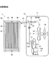
- the schematic configuration of the radiant air conditioner 1 will be described with reference to FIG.
- the radiant air conditioner 1 includes an outdoor unit 10 and a radiant panel 30.
- the radiation panel 30 is disposed indoors and corresponds to an indoor unit of a normal separate type air conditioner.
- the outdoor unit 10 houses a compressor 12, a four-way valve 13, an outdoor heat exchanger 14, an expansion valve 15, an outdoor blower 16, and the like in a housing 11 composed of sheet metal parts and synthetic resin parts. is doing.
- the outdoor unit 10 is connected to the radiation panel 30 by two refrigerant pipes 17 and 18.
- the refrigerant pipe 17 is intended to flow a liquid refrigerant, and a pipe that is thinner than the refrigerant pipe 18 is used. Therefore, the refrigerant pipe 17 may be referred to as “liquid pipe”, “narrow pipe”, or the like.
- the refrigerant pipe 18 is intended to flow a gaseous refrigerant, and is thicker than the refrigerant pipe 17. Therefore, the refrigerant pipe 18 may be referred to as “gas pipe”, “thick pipe”, or the like.
- HFC R410A or R32 is used as the refrigerant.
- a two-way valve 19 is provided in the refrigerant pipe connected to the refrigerant pipe 17, and a three-way valve 20 is provided in the refrigerant pipe connected to the refrigerant pipe 18.
- the two-way valve 19 and the three-way valve 20 are closed when the refrigerant pipes 17 and 18 are removed from the outdoor unit 10 to prevent the refrigerant from leaking from the outdoor unit 10 to the outside.
- the refrigerant is released through the three-way valve 20.
- the radiation panel 30 is often erected on the wall of the room, and a plurality of heat radiating portions 32 are arranged inside a front-shaped rectangular casing 31 made up of sheet metal parts and synthetic resin parts.
- heat radiating part it was named “heat radiating part” for simplicity, this part not only radiates heat to the surrounding air during heating operation, but also absorbs heat from the surrounding air during cooling operation.
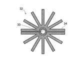
- the heat radiating part 32 is a cylindrical part and is arranged vertically. As shown in FIGS. 6 and 7, the basic configuration of the heat radiating section 32 is that the heat radiating fins 34 surround the central refrigerant pipe 33.
- the refrigerant pipe 33 and the heat radiating fins 34 are formed of a metal having good heat conductivity such as copper or aluminum and are in close contact with each other.
- the “vertical” referred to here is not limited to a strict vertical direction. The vertical direction including some inclination may be used.
- 6 and the heat dissipating fin 34 of FIG. 7 have a horizontal cross-sectional shape in which a plurality of fins are radially developed.
- 6 is formed as a part divided into two along the axial direction, and sandwiches the refrigerant tube 33 from the front and rear.
- the radiating fin 34 in FIG. 7 is a single component, and a refrigerant pipe 33 is inserted in a central portion corresponding to a wheel in terms of wheels.
- the structure of the heat dissipating part 32 shown in FIGS. 6 and 7 is merely an example, and heat dissipating fins 34 having different cross-sectional shapes can be used, or the refrigerant pipe 33 and the heat dissipating fins 34 can be combined in different ways. It is.
- a plurality (seven in the figure) of heat radiating portions 32 are arranged in the casing 31 so as to be parallel to each other.
- An opening 35 for exposing the heat radiating portion 32 is provided on the front surface of the housing 31.
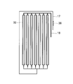
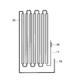
- the plurality of heat radiation portions 32 are all connected to the refrigerant pipes 17 and 18. In the connection configuration example shown in FIG. 3, all the heat radiating portions 32 are connected in parallel to the refrigerant pipes 17 and 18. In the connection configuration example shown in FIG. 4, all the heat radiating sections 32 are connected in series to the refrigerant pipes 17 and 18.
- a method other than the method shown in FIGS. 3 and 4 can also be adopted to connect the plurality of heat radiation portions 32.
- temperature detectors are arranged in the outdoor unit 10 and the radiation panel 30.
- a temperature detector 21 is disposed in the outdoor heat exchanger 14, and a temperature detector 22 is disposed in the discharge pipe 12 a serving as the discharge unit of the compressor 12, and the suction serving as the suction unit of the compressor 12.
- a temperature detector 23 is disposed in the pipe 12 b, and a temperature detector 24 is disposed in the refrigerant pipe between the expansion valve 15 and the two-way valve 19.
- a temperature detector 36 is disposed on the radiation panel 30.
- Each of the temperature detectors 21, 22, 23, 24, and 36 is formed of a thermistor.
- the temperature detector 36 is intended to measure the temperature of the heat radiating part 32, but is not directly attached to the heat radiating part 32, but is attached to the refrigerant pipe 17 for liquid refrigerant as shown in FIG.
- the reason for arranging the temperature detector 36 in the refrigerant pipe 17 is as follows. That is, since the temperature of the heat radiating portion 32 varies depending on the position (particularly the upper and lower positions), it is difficult to determine at which position the temperature detector 36 is disposed.
- the surface temperature of the heat radiating section 32 also depends on how the refrigerant path connecting the plurality of heat radiating sections 32 is designed.
- a temperature difference is likely to occur due to a pressure loss or a gas-liquid phase change of the refrigerant.
- a temperature difference may occur depending on the path.
- Some temperature detectors are covered with metal to improve temperature sensitivity. When the metal constituting the heat radiating portion 32 and the metal used in the temperature detector are different, a potential difference due to a different metal is generated at the contact portion, and there is a possibility of causing electric corrosion. In any case, it is not easy to determine at which position of the heat radiation part 32 the temperature detector 36 is arranged.
- the refrigerant pipe 17 is a location where the refrigerant throttled by the expansion valve 15 flows in during the cooling operation, and a location where the condensed refrigerant flows out from the heat radiating unit 32 during the heating operation.
- the temperature detector 36 is specifically referred to as “refrigerant pipe temperature detector 36”.
- the refrigerant in the gas-liquid two-phase state (however, the vaporization has not progressed so much and the liquid-phase refrigerant is abundant) flows through the refrigerant pipe 17 during the cooling operation, in other words, since the gas-liquid phase change of the refrigerant is small, the refrigerant The temperature of the pipe 17 can be handled as the temperature of the heat radiation part 32.
- the refrigerant pipe 17 becomes a supercooling part (liquid phase part) of the refrigeration cycle, and liquid refrigerant accumulates, so that the temperature of the refrigerant pipe 17 cannot be immediately handled as the temperature of the heat radiating part 32.
- the surface temperature of the heat radiating section 32 can be obtained from the measured temperature of the refrigerant pipe temperature detector 36 even during the heating operation based on the concept of “correction temperature” described later.
- the mounting position of the refrigerant pipe temperature detector 36 is a relatively higher part in the casing 31 of the refrigerant pipe 17. The reason why such a place is selected as the attachment position of the refrigerant pipe temperature detector 36 will be described later.
- a room temperature detector is disposed on the radiation panel 30.
- a room temperature detector 38 is disposed at the top of the housing 31, and a room temperature detector 39 is disposed at the bottom of the housing 31.
- the room temperature detector 38 is referred to as an “upper room temperature detector 38”
- the room temperature detector 39 is referred to as a “lower room temperature detector 39”.
- the upper room temperature detector 38 and the lower room temperature detector 39 are also composed of thermistors.
- the upper room temperature detector 38 and the lower room temperature detector 39 are arranged in a place that is not easily affected by the radiant heat of the heat radiating unit 32 and the radiant heat of the refrigerant pipes 17 and 18.
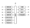
- the control unit 40 shown in FIG. 8 controls the overall control of the radiant air conditioner 1.
- the control unit 40 performs control so that the room temperature reaches a target value set by the user.
- the control unit 40 issues an operation command to the compressor 12, the four-way valve 13, the expansion valve 15, and the outdoor blower 16.
- the control unit 40 also receives output signals of the detected temperatures from the temperature detectors 21 to 24, the refrigerant pipe temperature detector 36, the upper room temperature detector 38, and the lower room temperature detector 39.
- the control unit 40 refers to the output signals from the temperature detectors 21 to 24, the refrigerant pipe temperature detector 36, the upper room temperature detector 38, and the lower room temperature detector 39, with respect to the compressor 12 and the outdoor fan 16.
- An operation command is issued, and a state switching command is issued to the four-way valve 13 and the expansion valve 15.
- FIG. 1 shows a state in which the radiant air conditioner 1 is performing a cooling operation (dehumidifying operation) or a defrosting operation.
- the high-temperature and high-pressure refrigerant discharged from the compressor 12 enters the outdoor heat exchanger 14 where heat exchange with outdoor air is performed. That is, the refrigerant dissipates heat to the outdoor air.
- the refrigerant that has dissipated heat and is condensed to be liquid is sent from the outdoor heat exchanger 14 to the heat dissipating part of the radiation panel 30 through the expansion valve 15, decompressed and expanded to a low temperature and low pressure, and the surface temperature of the heat dissipating part 32 is lowered .
- the heat dissipating part 32 whose surface temperature has dropped absorbs heat from the room air, thereby cooling the room air. After the heat absorption, the low-temperature gaseous refrigerant returns to the compressor 12. The airflow generated by the outdoor fan 16 promotes heat dissipation from the outdoor heat exchanger 14.
- FIG. 2 shows a state where the radiant air conditioner 1 is performing a heating operation.
- the four-way valve 13 is switched, and the refrigerant flow is reversed from that during the cooling operation. That is, the high-temperature and high-pressure refrigerant discharged from the compressor 12 enters the heat radiating section 32 where heat exchange with room air is performed. That is, the refrigerant dissipates heat to the room air, and the room air is warmed.
- the refrigerant that has dissipated heat and is condensed to become liquid is sent from the heat dissipating section 32 to the outdoor heat exchanger 14 through the expansion valve 15, and is decompressed and expanded to lower the surface temperature of the outdoor heat exchanger 14.
- the outdoor heat exchanger 14 whose surface temperature has dropped absorbs heat from outdoor air. After the heat absorption, the low-temperature gaseous refrigerant returns to the compressor 12. The airflow generated by the outdoor fan 16 promotes heat absorption by the outdoor heat exchanger 14. Frost adhering to the outdoor heat exchanger 14 due to heat absorption is removed by performing a defrosting operation.
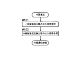
- FIG. 9 shows a control flowchart during cooling operation, which is an example of air conditioning operation in which the radiation panel 30 of the radiation type air conditioner 1 serves as an evaporator.
- the control unit 40 refers to the output signal of the upper room temperature detector 38 in step # 101. This is because the indoor air circulates as shown in FIG. 11 during the cooling operation, and the air passing through the upper room temperature detector 38 is not affected by the radiant heat of the heat radiating unit 32.
- the control unit 40 refers to the output signal of the refrigerant pipe temperature detector 36.
- the temperature detected by the refrigerant pipe temperature detector 36 can be handled as the surface temperature of the heat radiating unit 32, so that the control unit 40 can control the refrigerant pipe temperature detector 36. Reference the output signal without any correction.
- control unit 40 continues the cooling operation while performing Step # 101 and Step # 102 at a predetermined sampling rate.
- control unit 40 does not simply perform the control with reference to only the room temperature, but also performs the control with reference to the temperature of the refrigerant flowing through the heat radiating unit 32, so that the room temperature can be brought closer to the target temperature more quickly.
- the temperature detector 36 is attached to the inside of the casing 31 of the refrigerant pipe 17, whether the refrigerant path of the radiation panel 30 is the refrigerant path during the cooling operation or the refrigerant path during the heating operation. Regardless of, the surface temperature of the radiation panel 30 can be detected at the same position. For this reason, it is not necessary to change the control specifications between the cooling operation and the heating operation.
- condensed water is generated in the heat radiating section 32. Since the refrigerant pipe temperature detector 36 is attached to a relatively upper part of the refrigerant pipe 17 in the housing 31, even if the condensed water in the heat radiating section 32 is accumulated as drain water below the heat radiating section 32 ( The drain water is received by a drain pan 32a ⁇ refer to FIG. 11 >> disposed below the heat radiating portion 32) and is not in contact with the drain water. For this reason, there is no need to worry that an error occurs in the temperature detected by the refrigerant pipe temperature detector 36 or that the refrigerant pipe temperature detector 36 breaks down.
- the refrigerant pipe temperature detector 36 is provided in the upper part of the refrigerant pipe 17. It is. In FIG. 1, a refrigerant pipe temperature detector 36 is provided in the refrigerant pipe 17 that passes through the upper frame of the housing 31 above the heat radiating section 32.
- the refrigerant pipe temperature detecting portion 36 is disposed in the upper portion of the refrigerant pipe 17.
- the refrigerant pipe temperature detector 36 can be attached to the refrigerant pipe 37 that connects the heat radiation parts 32 to each other in the upper part of the radiation panel 30. Even with this configuration, the refrigerant pipe temperature detector 36 can be protected from condensed water. In short, the fact that the refrigerant pipe temperature detector 36 is arranged at a place where the condensed water hardly occurs is a matter to be protected.
- FIG. 10 shows a control flowchart during heating operation, which is an example of air conditioning operation in which the radiation panel 30 of the radiant air conditioner 1 serves as a condenser.
- the control unit 40 refers to the output signal of the lower room temperature detector 39 in step # 111. This is because the indoor air circulates as shown in FIG. 12 during the heating operation, and the air passing through the lower room temperature detector 39 is not affected by the radiant heat of the heat radiating unit 32.
- control unit 40 refers to the temperature obtained by adding the correction temperature to the temperature detected by the refrigerant pipe temperature detector 36.
- the refrigerant pipe temperature detector 36 is disposed in the refrigerant pipe 17 and does not directly detect the surface temperature of the radiation panel 30 (more precisely, the surface temperature of the heat radiating portion 32). Further, the difference between the temperature of the refrigerant pipe 17 and the surface temperature of the radiation panel 30 varies depending on what value the degree of supercooling is. Therefore, during the heating operation, the surface temperature of the radiation panel 30 is predicted by correcting the temperature by predicting the degree of supercooling of the heat radiating unit 32 from the temperature of the refrigerant pipe 17. It is preferable to determine the correction temperature through repeated experiments.
- control unit 40 continues the heating operation while performing Step # 111 and Step # 112 at a predetermined sampling rate.
- control unit 40 does not perform the control with reference to only the room temperature during the heating operation, but corrects the temperature by predicting the degree of supercooling of the heat radiating unit 32 from the temperature of the refrigerant pipe 17. Since the control is performed with reference to the predicted surface temperature of the high radiation panel 30, the room temperature can be brought closer to the target temperature more quickly.
- the upper room temperature detector 38 and the lower room temperature detector 39 are provided as means for measuring the room temperature, and does not limit the invention.
- a third or higher room temperature detector is disposed at an intermediate height between the upper room temperature detector 38 and the lower room temperature detector 39, and the control unit 40 performs control while referring to the measurement results. It is good as well.
- the room temperature detectors other than the upper room temperature detector 38 and the lower room temperature detector 39 should also be arranged in a place that is not easily affected by the radiant heat of the heat radiating section 32 and the radiant heat of the refrigerant pipes 17 and 18.
- the heat radiation unit 32 has been described as being arranged vertically, but a configuration in which the heat radiation unit 32 is arranged horizontally is also possible.
- the heat dissipating fins 34 may be configured by arranging a large number of thin plates perpendicular to the axis of the refrigerant pipe 33 with a space therebetween.
- the present invention can be widely used for a radiation type air conditioner.
Landscapes
- Engineering & Computer Science (AREA)
- Chemical & Material Sciences (AREA)
- Combustion & Propulsion (AREA)
- Mechanical Engineering (AREA)
- General Engineering & Computer Science (AREA)
- Physics & Mathematics (AREA)
- Thermal Sciences (AREA)
- Life Sciences & Earth Sciences (AREA)
- Sustainable Development (AREA)
- Atmospheric Sciences (AREA)
- Air Conditioning Control Device (AREA)
- Devices For Blowing Cold Air, Devices For Blowing Warm Air, And Means For Preventing Water Condensation In Air Conditioning Units (AREA)
Abstract
輻射式空気調和機(1)は、室内に配置される輻射パネル(30)と、室外側熱交換器(14)と、輻射パネル及び室外側熱交換器に冷媒配管(17)(18)を通じて冷媒を循環させる圧縮機(12)と、制御部(40)とを備える。輻射パネルは筐体(31)内に放熱部(32)を配置したものである。輻射パネルの上部には上部室温検出器(38)が配置され、輻射パネルの下部には下部室温検出器(39)が配置される。制御部は上部室温検出器、または下部室温検出器からの出力信号を参照して制御を行う。
Description
本発明は輻射式空気調和機に関する。
家屋用のヒートポンプ式空気調和機で、室外機と室内機に分かれたいわゆるセパレート型の空気調和機では、室外機に熱交換器とファンが設けられるとともに、室内機にも熱交換器とファンが設けられるのが通常の構造である。これに対し、同じセパレート型の空気調和機であっても、室内機の熱交換器を輻射パネルとして構成し、ファンを用いることなく、熱の輻射により室内の冷房または暖房を行うタイプのものも存在する。その例を特許文献1~3に見ることができる。
特許文献1に記載された空気調和機は建屋の天井に配設される輻射パネルを備える。輻射パネルの内部には冷媒配管が蛇行状に配置されている。冷房運転時には輻射パネルで吸熱がなされて輻射式冷房が行われる。暖房運転時には輻射パネルで放熱がなされて輻射式暖房が行われる。輻射式冷暖房は室内ファンによる空気の攪拌や騒音と無縁であり、静粛で快適な冷暖房を行うことができる。
特許文献2には、室内の複数面に輻射パネルを配置したり、一面でも複数枚の輻射パネルを設置したりするなど、複数枚の輻射パネルを用いて冷暖房を行う空気調和装置が記載されている。この空気調和装置では各輻射パネルの表面に表面温検出器が取り付けられ、各輻射パネルの負荷に応じて各輻射パネルへの熱媒体の流量が制御される。
特許文献3には、ファンコイルユニットと輻射パネルの両方で室温制御を行うと同時に輻射面温度を制御することのできる輻射空気調和装置が記載されている。
特許文献3に記載の空気調和装置のように、送風機を備えたファンコイルユニットと輻射パネルを併用するものは別として、輻射パネルのみで冷暖房を行う空気調和機では、室内に風の流れを積極的に生成する動力源がないため、室温を適切に検出することができない。そのため、輻射パネル温度のみを参照して制御を行っており、快適な室温となるように制御を行うという点でやや難点がある。
室温をも参照しつつ制御を行うことが輻射式空気調和機にも求められるが、室温を測定するための温度検出器を、通常のやり方で輻射パネルに配置したのでは、輻射パネルの放熱部が発する輻射熱や、冷媒配管が発する輻射熱などの影響を受け、測定結果が歪められてしまう。リモートコントローラ等、輻射パネルから離れた箇所で用いられる要素に室温検出器を配置すれば、輻射パネルの放熱部が発する輻射熱や、冷媒配管が発する輻射熱などの影響を懸念せずに済むが、今度は室温測定結果をどのように伝達するかが問題となる。仮に無線通信で行うこととすれば、サンプリングレートに合わせて無線通信を行わねばならないことになり、リモートコントローラの場合であれば電池の消耗を早めてしまう。
本発明は上記問題に鑑みなされたものであり、送風機を備えない無風タイプの輻射式空気調和機であっても適切に室温を検出し、きめの細かい、快適な空調制御を行えるようにすることを目的とする。
本発明に係る輻射式空気調和機は、室内に配置される輻射パネルと、室外側熱交換器と、前記輻射パネル及び前記室外側熱交換器に冷媒配管を通じて冷媒を循環させる圧縮機と、制御部と、を備え、前記輻射パネルは筐体内に放熱部を配置したものであり、前記輻射パネルの上部には上部室温検出器が配置され、前記輻射パネルの下部には下部室温検出器が配置され、前記制御部は前記上部室温検出器、または前記下部室温検出器からの出力信号を参照して制御を行う。
輻射パネルが蒸発器となる空気調和運転時(例えば、冷房運転時)には輻射パネルの上部から下部に向かう気流が発生し、輻射パネルの上部で迎える空気が放熱部の輻射熱の影響を受けていない空気ということになる。輻射パネルが凝縮器となる空気調和運転時(例えば、暖房運転時)には輻射パネルの下部から上部に向かう気流が発生し、輻射パネルの下部で迎える空気が放熱部の輻射熱の影響を受けていない空気ということになる。輻射パネルの上部と下部のそれぞれに室温検出器を配置することにより、輻射パネルが蒸発器となる空気調和運転時にも輻射パネルが凝縮器となる空気調和運転時にも、放熱部の輻射熱の影響を受けていない室内空気の温度を測定することができるから、適切に室温を知り、きめの細かい、快適な空調制御を行うことができる。
上記構成の輻射式空気調和機において、前記制御部は、冷房運転時には前記上部室温検出器からの出力信号を参照して制御を行い、暖房運転時には前記下部室温検出器からの出力信号を参照して制御を行うことが好ましい。
この構成によると、冷房運転時には放熱部の輻射熱の影響を受けていない室内空気の温度を上部室温検出器で測定し、暖房運転時には放熱部の輻射熱の影響を受けていない室内空気の温度を下部室温検出器で測定するから、温度を変えるべき室内空気の温度を適切に把握して、きめの細かい、快適な空調制御を行うことができる。
上記構成の輻射式空気調和機において、前記放熱部に接続される冷媒配管の前記筐体内部分に当該冷媒配管の温度を検出する冷媒配管温度検出器が取り付けられ、前記制御部は前記冷媒配管温度検出器からの出力信号も参照しつつ制御を行うことが好ましい。
この構成によると、制御部は、単に室温のみを参照して制御を行うのでなく、放熱部を流れる冷媒の温度も参照しながら制御を行うから、より速やかに室温を目標温度に近づけることができる。また、輻射パネルの冷媒経路が冷房運転時の冷媒経路であるか暖房運転時の冷媒経路であるかに関係なく、同じ位置で輻射パネルの表面温度を検出できるので、冷房運転時と暖房運転時とで制御の仕様を変える必要がない。さらに、冷媒配管温度検出器が輻射パネルの表面にではなく冷媒配管に取り付けられるから、結露水が冷媒配管温度検出器を濡らす可能性が少なく、冷媒配管温度検出器が誤検出する可能性を低くできる。
上記構成の輻射式空気調和機において、前記冷媒配管温度検出器が取り付けられる前記冷媒配管は液体冷媒用の冷媒配管であり、前記制御部は、冷房運転時は前記冷媒配管温度検出器が検出した温度を前記輻射パネルの表面温度として参照し、暖房運転時は前記冷媒配管温度検出器が検出した温度に補正温度を加えた温度を前記輻射パネルの表面温度として参照することが好ましい。
この構成によると、暖房運転時、冷媒配管の温度から放熱部の過冷却度を予測して温度を補正することにより、輻射パネルの表面温度を正確に予測することができる。
本発明によると、冷房運転時にも暖房運転時にも、放熱部の輻射熱の影響を受けていない室内空気の温度を測定することで適切に室温を知り、きめの細かい、快適な空調制御を行うことができる。
図1に基づき輻射式空気調和機1の概略構成を説明する。輻射式空気調和機1は室外機10と輻射パネル30により構成される。輻射パネル30は室内に配置されるものであり、通常のセパレート型空気調和機の室内機に相当する。
室外機10は、板金製部品と合成樹脂製部品により構成される筐体11の内部に、圧縮機12、四方弁13、室外側熱交換器14、膨張弁15、室外側送風機16などを収納している。
室外機10は2本の冷媒配管17、18で輻射パネル30に接続される。冷媒配管17は液体の冷媒を流すことを目的としており、冷媒配管18に比較して細い管が用いられている。そのため冷媒配管17は「液管」「細管」などと称されることがある。冷媒配管18は気体の冷媒を流すことを目的としており、冷媒配管17に比較して太い管が用いられている。そのため冷媒配管18は「ガス管」「太管」などと称されることがある。冷媒には例えばHFC系のR410AやR32等が用いられる。
室外機10の内部の冷媒配管で、冷媒配管17に接続される冷媒配管には二方弁19が設けられ、冷媒配管18に接続される冷媒配管には三方弁20が設けられる。二方弁19と三方弁20は、室外機10から冷媒配管17、18が取り外されるときに閉じられ、室外機10から外部に冷媒が漏れることを防ぐ。室外機10から、あるいは輻射パネル30を含めた冷凍サイクル全体から、冷媒を放出する必要があるときは、三方弁20を通じて放出が行われる。
輻射パネル30は室内の壁際に立設されることが多く、板金製部品と合成樹脂製部品により構成される正面形状矩形の筐体31の内部に複数の放熱部32が配置されている。簡潔さを尊び「放熱部」と命名したが、この部品は暖房運転時に周囲の空気に対し放熱を行うだけでなく、冷房運転時に周囲の空気から吸熱を行うものでもある。
放熱部32は筒状の部品であり、垂直に配置される。図6、7に示すように、中心の冷媒管33を放熱フィン34が取り囲む、というのが放熱部32の基本的な構成である。冷媒管33と放熱フィン34は銅やアルミニウムのような熱伝導の良い金属で形成され、互いに密着する。なお、ここで言う「垂直」とは厳密な垂直方向に限られない。多少の傾きを含む垂直方向であってもよい。
図6の放熱フィン34も図7の放熱フィン34も複数のフィンが放射状に展開する水平断面形状を有している。図6の放熱フィン34は軸線方向に沿って二つ割りにされた部品として形成され、冷媒管33を前後から挟み込んでいる。図7の放熱フィン34は単一の部品であり、中心の、車輪で言えばハブに相当する部分に冷媒管33が挿入されている。言うまでもないが、図6、7に示す放熱部32の構造は単なる例示であり、異なる断面形状の放熱フィン34を用いることもできるし、冷媒管33と放熱フィン34を異なる様式で組み合わせることも可能である。
筐体31の内部に複数(図においては7本)の放熱部32が互いに並行するように配置される。筐体31の前面には放熱部32を露出させる開口部35が設けられている。複数の放熱部32は全て冷媒配管17、18に接続される。図3に示す接続構成例では全ての放熱部32が冷媒配管17、18に並列接続される。図4に示す接続構成例では全ての放熱部32を直列接続したものが冷媒配管17、18に接続されている。
複数の放熱部32を接続するのに、図3、4に示した方式以外の方式を採用することもできる。例えば、複数の放熱部32を所定本数ずつグループ分けし、同一グループに属する放熱部32は互いに並列接続し、グループ同士を直列接続するといった方式も可能である。あるいは、複数の放熱部32を所定本数ずつグループ分けし、同一グループに属する放熱部32は直列接続し、グループ同士を並列接続するといった方式も可能である。
輻射式空気調和機1の運転制御を行う上で、各所の温度を知ることが不可欠である。この目的のため、室外機10と輻射パネル30に温度検出器が配置される。室外機10においては、室外側熱交換器14に温度検出器21が配置され、圧縮機12の吐出部となる吐出管12aに温度検出器22が配置され、圧縮機12の吸入部となる吸入管12bに温度検出器23が配置され、膨張弁15と二方弁19の間の冷媒配管に温度検出器24が配置されている。輻射パネル30には温度検出器36が配置される。温度検出器21、22、23、24、36はいずれもサーミスタにより構成される。
温度検出器36は放熱部32の温度測定を目的とするが、放熱部32に直接取り付けられるのでなく、図3に示す通り、液体冷媒用の冷媒配管17に取り付けられる。温度検出器36を冷媒配管17に配置するのは次の理由による。すなわち放熱部32は位置(特に上下の位置)によって温度が異なるため、どの位置に温度検出器36を配置するかを決めるのが難しい。
複数の放熱部32を結ぶ冷媒経路がどのように設計されているかによっても放熱部32の表面温度は左右される。冷媒経路が単一経路の場合、圧力損失や冷媒の気液相変化によって温度差が生じやすい。冷媒経路が複数経路の場合、経路によって温度差が生じる可能性がある。また、温度検出器には感温性を良くするために金属で覆われているものがある。放熱部32を構成する金属と温度検出器に使われている金属の種類が異なる場合、それらの接触部において異種金属による電位差が生じ、電蝕を起こす可能性がある。いずれにしても、放熱部32のどの位置に温度検出器36を配置するかを決めるのは容易ではない。
筐体31の内部の冷媒配管17を温度検出器36の取付箇所とすれば、上記の問題は解消される。冷媒配管17は、冷房運転時には膨張弁15で絞られた冷媒が流入する箇所であり、暖房運転時には凝縮した冷媒が放熱部32から流出する箇所である。以後、温度検出器36のみを特別に「冷媒配管温度検出器36」と呼称する。
冷房運転時には冷媒配管17に気液二相状態の冷媒(ただし、気化があまり進んでいない、液相冷媒が多い状態の冷媒)が流れるので、言い換えれば冷媒の気液相変化が少ないので、冷媒配管17の温度を放熱部32の温度として取り扱うことができる。一方、暖房運転時には冷媒配管17は冷凍サイクルの過冷却部(液相部)となり、液体の冷媒が溜まるため、冷媒配管17の温度を直ちに放熱部32の温度として取り扱うことはできない。しかしながら、後述する「補正温度」の考え方により、暖房運転時においても冷媒配管温度検出器36の測定温度から放熱部32の表面温度を求めることができる。
冷媒配管温度検出器36の取付位置は、冷媒配管17の筐体31内部分の中でも比較的上位にある部分とされる。このような場所を冷媒配管温度検出器36の取付位置として選択した理由は後で説明する。
輻射パネル30には冷媒配管温度検出器36に加えて室温検出器が配置される。筐体31の上部には室温検出器38が配置され、筐体31の下部には室温検出器39が配置される。以後、室温検出器38を「上部室温検出器38」と呼称し、室温検出器39を「下部室温検出器39」と呼称する。温度検出器21、22、23、24及び冷媒配管温度検出器36と同じく、上部室温検出器38と下部室温検出器39もサーミスタにより構成される。上部室温検出器38と下部室温検出器39は、放熱部32の輻射熱や冷媒配管17、18の輻射熱の影響を受けにくい箇所に配置する。
輻射式空気調和機1の全体制御を司るのは図8に示す制御部40である。制御部40は室内温度が使用者によって設定された目標値に達するように制御を行う。
制御部40は、圧縮機12、四方弁13、膨張弁15、及び室外側送風機16に対して動作指令を発する。また制御部40は温度検出器21~24、冷媒配管温度検出器36、上部室温検出器38、及び下部室温検出器39からそれぞれの検出温度の出力信号を受け取る。制御部40は、温度検出器21~24、冷媒配管温度検出器36、上部室温検出器38、及び下部室温検出器39からの出力信号を参照しつつ、圧縮機12と室外側送風機16に対し運転指令を発し、四方弁13と膨張弁15に対しては状態切り替えの指令を発する。
図1は輻射式空気調和機1が冷房運転(除湿運転)あるいは除霜運転を行っている状態を示す。圧縮機12から吐出された高温高圧の冷媒は室外側熱交換器14に入り、そこで室外空気との熱交換が行われる。すなわち冷媒は室外空気に対し放熱を行う。放熱し、凝縮して液状となった冷媒は室外側熱交換器14から膨張弁15を通じて輻射パネル30の放熱部に送られ、減圧し膨張して低温低圧となり、放熱部32の表面温度を下げる。表面温度の下がった放熱部32は室内空気から吸熱し、これにより室内空気は冷やされる。吸熱後、低温の気体状の冷媒は圧縮機12に戻る。室外側送風機16によって生成された気流が室外側熱交換器14からの放熱を促進する。
図2は輻射式空気調和機1が暖房運転を行っている状態を示す。この時は四方弁13が切り替えられて冷房運転時と冷媒の流れが逆になる。すなわち、圧縮機12から吐出された高温高圧の冷媒は放熱部32に入り、そこで室内空気との熱交換が行われる。すなわち冷媒は室内空気に対し放熱を行い、室内空気は暖められる。放熱し、凝縮して液状となった冷媒は放熱部32から膨張弁15を通じて室外側熱交換器14に送られ、減圧し膨張して室外側熱交換器14の表面温度を下げる。表面温度の下がった室外側熱交換器14は室外空気から吸熱する。吸熱後、低温の気体状の冷媒は圧縮機12に戻る。室外側送風機16によって生成された気流が室外側熱交換器14による吸熱を促進する。吸熱により室外側熱交換器14に付着した霜は、除霜運転を行うことにより取り除かれる。
輻射式空気調和機1の輻射パネル30が蒸発器となる空気調和運転の一例である冷房運転時の制御フローチャートを図9に示す。冷房運転開始後、ステップ#101で制御部40は、上部室温検出器38の出力信号を参照する。冷房運転時には室内の空気が図11のように循環し、上部室温検出器38を通過する空気が放熱部32の輻射熱の影響を受けていない空気ということになるからである。
次のステップ#102で、制御部40は冷媒配管温度検出器36の出力信号を参照する。冷房運転(除湿運転)あるいは除霜運転の場合には、冷媒配管温度検出器36が検出した温度を放熱部32の表面温度として取り扱うことができるため、制御部40は冷媒配管温度検出器36の出力信号を、補正を加えることなく参照する。
以後制御部40は、所定のサンプリングレートでステップ#101とステップ#102を遂行しつつ冷房運転を継続する。
このように制御部40は、単に室温のみを参照して制御を行うのでなく、放熱部32を流れる冷媒の温度も参照しながら制御を行うから、より速やかに室温を目標温度に近づけることができる。
前述の通り、温度検出器36は冷媒配管17の筐体31内部分に取り付けられているので、輻射パネル30の冷媒経路が冷房運転時の冷媒経路であるか暖房運転時の冷媒経路であるかに関係なく、同じ位置で輻射パネル30の表面温度を検出できる。このため、冷房運転時と暖房運転時とで制御の仕様を変える必要がない。
冷房運転(除湿運転)時、放熱部32には結露水が発生する。冷媒配管温度検出器36は筐体31内の冷媒配管17の中でも比較的上位の部分に取り付けられているので、放熱部32の結露水が放熱部32の下方にドレン水として溜まったとしても(ドレン水は放熱部32の下方に配置されたドレンパン32a《図11参照》に受けられる)、ドレン水に接触せずにいられる。このため、冷媒配管温度検出器36の検出温度に誤りが生じたり、冷媒配管温度検出器36が故障したりすることを懸念せずに済む。放熱部32ほどではないにせよ、冷媒配管17にも結露水が生じるが、その結露水による影響を小さくする上でも、冷媒配管17の上位部分に冷媒配管温度検出器36を配置することは有意義である。なお、図1においては、放熱部32よりも上方の筐体31の上枠内を通る冷媒配管17に冷媒配管温度検出器36を設けている。
図4のように複数の放熱部32を直列接続した場合においても、冷媒配管温度検出部36は冷媒配管17の上位部分に配置する。また複数の放熱部32を直列接続している場合、図5に示す通り、輻射パネル30の上部において放熱部32同士を接続する冷媒配管37に冷媒配管温度検出器36を取り付けることもできる。この構成であっても冷媒配管温度検出器36を結露水から保護できる。要は、結露水の発生しにくい箇所に冷媒配管温度検出器36を配置する、というのが守るべき事柄である。
輻射式空気調和機1の輻射パネル30が凝縮器となる空気調和運転の一例である暖房運転時の制御フローチャートを図10に示す。暖房運転開始後、ステップ#111で制御部40は、下部室温検出器39の出力信号を参照する。暖房運転時には室内の空気が図12のように循環し、下部室温検出器39を通過する空気が放熱部32の輻射熱の影響を受けていない空気ということになるからである。
次のステップ#112で、制御部40は冷媒配管温度検出器36が検出した温度に補正温度を加えた温度を参照する。
前述の通り冷媒配管温度検出器36は冷媒配管17に配置されており、輻射パネル30の表面温度(より正確に言うならば放熱部32の表面温度)を直接検出するものではない。また、過冷却度がどのような値になるかによっても冷媒配管17の温度と輻射パネル30の表面温度の差が変化する。そこで暖房運転時には、冷媒配管17の温度から放熱部32の過冷却度を予測して温度を補正することにより、輻射パネル30の表面温度を予測する。補正温度は実験を重ねて決定することが好ましい。
以後制御部40は、所定のサンプリングレートでステップ#111とステップ#112を遂行しつつ暖房運転を継続する。
このように制御部40は、暖房運転時、単に室温のみを参照して制御を行うのでなく、冷媒配管17の温度から放熱部32の過冷却度を予測して温度を補正した、正確性の高い輻射パネル30の予測表面温度を参照しながら制御を行うから、より速やかに室温を目標温度に近づけることができる。
室温を測定する手段として上部室温検出器38と下部室温検出器39を設けるというのは最低条件であり、発明を限定するものではない。上部室温検出器38と下部室温検出器39の中間の高さのところに第三の、あるいはそれ以上の室温検出器を配置し、それらの測定結果をも参照しつつ制御部40が制御を行うこととしてもよい。なお、上部室温検出器38と下部室温検出器39以外の室温検出器についても放熱部32の輻射熱や冷媒配管17、18の輻射熱の影響を受けにくい箇所に配置すべきであることは言うまでもない。
これまで、放熱部32は垂直に配置するものとして話を進めてきたが、放熱部32を水平に配置する構成も可能である。その場合の放熱フィン34は、冷媒管33の軸線に直交する薄板を、互いの間に間隔を置いて多数配置する構成とするのがよい。
以上、本発明の実施形態につき説明したが、本発明の範囲はこれに限定されるものではなく、発明の主旨を逸脱しない範囲で種々の変更を加えて実施することができる。
本発明は輻射式空気調和機に広く利用可能である。
1 輻射式空気調和機
10 室外機
11 筐体
12 圧縮機
13 四方弁
14 室外側熱交換器
15 膨張弁
16 室外側送風機
17、18 冷媒配管
30 輻射パネル
31 筐体
32 放熱部
36 冷媒配管温度検出器
38 上部室温検出器
39 下部室温検出器
40 制御部
10 室外機
11 筐体
12 圧縮機
13 四方弁
14 室外側熱交換器
15 膨張弁
16 室外側送風機
17、18 冷媒配管
30 輻射パネル
31 筐体
32 放熱部
36 冷媒配管温度検出器
38 上部室温検出器
39 下部室温検出器
40 制御部
Claims (4)
- 輻射式空気調和機であって、以下の構成を備えるもの:
室内に配置される輻射パネルと、
室外側熱交換器と、
前記輻射パネル及び前記室外側熱交換器に冷媒配管を通じて冷媒を循環させる圧縮機と、
制御部と、
を備え、
前記輻射パネルは筐体内に放熱部を配置したものであり、
前記輻射パネルの上部には上部室温検出器が配置され、前記輻射パネルの下部には下部室温検出器が配置され、
前記制御部は前記上部室温検出器、または前記下部室温検出器からの出力信号を参照して制御を行う。 - 請求項1の輻射式空気調和機であって、以下の構成を備えるもの:
前記制御部は、冷房運転時には前記上部室温検出器からの出力信号を参照して制御を行い、暖房運転時には前記下部室温検出器からの出力信号を参照して制御を行う。 - 請求項1または2の輻射式空気調和機であって、以下の構成を備えるもの:
前記放熱部に接続される冷媒配管の前記筐体内部分に当該冷媒配管の温度を検出する冷媒配管温度検出器が取り付けられ、
前記制御部は前記冷媒配管温度検出器からの出力信号も参照しつつ制御を行う。 - 請求項3の輻射式空気調和機であって、以下の構成を備えるもの:
前記冷媒配管温度検出器が取り付けられる前記冷媒配管は液体冷媒用の冷媒配管であり、
前記制御部は、冷房運転時は前記冷媒配管温度検出器が検出した温度を前記輻射パネルの表面温度として参照し、暖房運転時は前記冷媒配管温度検出器が検出した温度に補正温度を加えた温度を前記輻射パネルの表面温度として参照する。
Priority Applications (3)
| Application Number | Priority Date | Filing Date | Title |
|---|---|---|---|
| CN201380038313.XA CN104541110B (zh) | 2012-09-21 | 2013-09-17 | 辐射式空气调节机 |
| KR1020157004001A KR101656631B1 (ko) | 2012-09-21 | 2013-09-17 | 복사식 공기 조화기 |
| SE1550060A SE1550060A1 (sv) | 2012-09-21 | 2013-09-17 | Radiant air conditioner |
Applications Claiming Priority (2)
| Application Number | Priority Date | Filing Date | Title |
|---|---|---|---|
| JP2012-208034 | 2012-09-21 | ||
| JP2012208034A JP5961084B2 (ja) | 2012-09-21 | 2012-09-21 | 輻射式空気調和機 |
Publications (1)
| Publication Number | Publication Date |
|---|---|
| WO2014046084A1 true WO2014046084A1 (ja) | 2014-03-27 |
Family
ID=50341394
Family Applications (1)
| Application Number | Title | Priority Date | Filing Date |
|---|---|---|---|
| PCT/JP2013/075027 Ceased WO2014046084A1 (ja) | 2012-09-21 | 2013-09-17 | 輻射式空気調和機 |
Country Status (5)
| Country | Link |
|---|---|
| JP (1) | JP5961084B2 (ja) |
| KR (1) | KR101656631B1 (ja) |
| CN (1) | CN104541110B (ja) |
| SE (1) | SE1550060A1 (ja) |
| WO (1) | WO2014046084A1 (ja) |
Families Citing this family (5)
| Publication number | Priority date | Publication date | Assignee | Title |
|---|---|---|---|---|
| CN105180371B (zh) * | 2015-09-30 | 2018-11-13 | 青岛海尔空调器有限总公司 | 一种检测室温的方法及空调器 |
| CN105241029A (zh) * | 2015-11-03 | 2016-01-13 | 青岛海尔空调器有限总公司 | 辐射空调的运行控制方法 |
| CN106196296A (zh) * | 2016-08-25 | 2016-12-07 | 可玛思(天津)金属制品有限公司 | 一种与热泵室外机连接的无风室内空调及其工作方法 |
| JP6960347B2 (ja) * | 2018-02-06 | 2021-11-05 | ダイキン工業株式会社 | 輻射パネル及び空気調和装置 |
| CN114811855B (zh) * | 2022-04-26 | 2023-09-08 | 浙江中广电器集团股份有限公司 | 一种空调及其控制方法 |
Citations (7)
| Publication number | Priority date | Publication date | Assignee | Title |
|---|---|---|---|---|
| JPH08166155A (ja) * | 1994-12-12 | 1996-06-25 | Toshiba Corp | 空気調和機 |
| JPH0960900A (ja) * | 1995-08-18 | 1997-03-04 | Philips Japan Ltd | 温度センサ付きオイルヒータ |
| GB2378502A (en) * | 2001-06-06 | 2003-02-12 | Ltg Ag | Apparatus for heating or cooling a room |
| EP1795825A1 (en) * | 2005-12-12 | 2007-06-13 | AERMEC S.p.A. | Equipment for supplying chilled fluid for an air conditioning installation and air conditioning installation with said equipment |
| JP2008139007A (ja) * | 2006-11-06 | 2008-06-19 | Sekisui Chem Co Ltd | 輻射式空調装置 |
| JP2012013401A (ja) * | 2010-07-05 | 2012-01-19 | Panasonic Electric Works Co Ltd | サーキュレーション装置及びサーキュレーション装置の通気構造 |
| JP2012172899A (ja) * | 2011-02-21 | 2012-09-10 | Inaba Denki Sangyo Co Ltd | 空調装置 |
Family Cites Families (8)
| Publication number | Priority date | Publication date | Assignee | Title |
|---|---|---|---|---|
| JPH04320752A (ja) | 1991-04-18 | 1992-11-11 | Matsushita Electric Ind Co Ltd | 空気調和装置 |
| JP3406442B2 (ja) * | 1995-12-27 | 2003-05-12 | 東芝キヤリア株式会社 | 空気調和機 |
| JPH09287800A (ja) * | 1996-04-18 | 1997-11-04 | Sanyo Electric Co Ltd | 空気調和装置 |
| JPH10205802A (ja) | 1997-01-27 | 1998-08-04 | Sanyo Electric Co Ltd | 輻射式空気調和装置 |
| JPH11132605A (ja) * | 1997-10-29 | 1999-05-21 | Toshiba Corp | 空気調和機 |
| JP2000283535A (ja) | 1999-03-31 | 2000-10-13 | Mitsubishi Electric Corp | 輻射空気調和装置 |
| CN101504179B (zh) * | 2009-02-27 | 2011-04-06 | 海信(山东)空调有限公司 | 一种制冷模式下空调器故障传感器的替代控制方法 |
| CN102506490B (zh) * | 2011-11-09 | 2013-12-04 | 宁波奥克斯电气有限公司 | 一拖多变频空调制冷时室内机电子膨胀阀的控制方法 |
-
2012
- 2012-09-21 JP JP2012208034A patent/JP5961084B2/ja not_active Expired - Fee Related
-
2013
- 2013-09-17 WO PCT/JP2013/075027 patent/WO2014046084A1/ja not_active Ceased
- 2013-09-17 SE SE1550060A patent/SE1550060A1/sv not_active Application Discontinuation
- 2013-09-17 CN CN201380038313.XA patent/CN104541110B/zh not_active Expired - Fee Related
- 2013-09-17 KR KR1020157004001A patent/KR101656631B1/ko not_active Expired - Fee Related
Patent Citations (7)
| Publication number | Priority date | Publication date | Assignee | Title |
|---|---|---|---|---|
| JPH08166155A (ja) * | 1994-12-12 | 1996-06-25 | Toshiba Corp | 空気調和機 |
| JPH0960900A (ja) * | 1995-08-18 | 1997-03-04 | Philips Japan Ltd | 温度センサ付きオイルヒータ |
| GB2378502A (en) * | 2001-06-06 | 2003-02-12 | Ltg Ag | Apparatus for heating or cooling a room |
| EP1795825A1 (en) * | 2005-12-12 | 2007-06-13 | AERMEC S.p.A. | Equipment for supplying chilled fluid for an air conditioning installation and air conditioning installation with said equipment |
| JP2008139007A (ja) * | 2006-11-06 | 2008-06-19 | Sekisui Chem Co Ltd | 輻射式空調装置 |
| JP2012013401A (ja) * | 2010-07-05 | 2012-01-19 | Panasonic Electric Works Co Ltd | サーキュレーション装置及びサーキュレーション装置の通気構造 |
| JP2012172899A (ja) * | 2011-02-21 | 2012-09-10 | Inaba Denki Sangyo Co Ltd | 空調装置 |
Also Published As
| Publication number | Publication date |
|---|---|
| CN104541110A (zh) | 2015-04-22 |
| JP2014062681A (ja) | 2014-04-10 |
| CN104541110B (zh) | 2017-04-05 |
| JP5961084B2 (ja) | 2016-08-02 |
| KR20150033728A (ko) | 2015-04-01 |
| KR101656631B1 (ko) | 2016-09-09 |
| SE1550060A1 (sv) | 2015-01-22 |
Similar Documents
| Publication | Publication Date | Title |
|---|---|---|
| JP5869955B2 (ja) | 輻射式空気調和機 | |
| JP5898569B2 (ja) | 輻射式空気調和機 | |
| JP6095677B2 (ja) | ヒートポンプ装置 | |
| ES2750251T3 (es) | Acondicionador de aire | |
| CN103597290B (zh) | 温度调节系统、空调系统 | |
| JP6184503B2 (ja) | 油面検知装置及びこの油面検知装置を搭載した冷凍空調装置 | |
| WO2014017161A1 (ja) | 冷凍空調装置、冷媒漏洩検知装置及び冷媒漏洩検知方法 | |
| JP5961084B2 (ja) | 輻射式空気調和機 | |
| CN103604168A (zh) | 冷暖型空调器 | |
| JP2014102050A (ja) | 冷凍装置 | |
| JP5898568B2 (ja) | 輻射式空気調和機 | |
| CN204629840U (zh) | 空调器 | |
| JP2013194968A (ja) | 熱交換器及びそれを搭載した空気調和機 | |
| JP5447438B2 (ja) | 冷蔵庫 | |
| JP2012149845A (ja) | 空気調和装置のユニット及び空気調和装置 | |
| JP6139093B2 (ja) | パラレルフロー型熱交換器 | |
| JP5937421B2 (ja) | 輻射式空気調和機 | |
| JP6310077B2 (ja) | 熱源システム | |
| JP2013245829A (ja) | 輻射式空気調和機 | |
| JP4605725B2 (ja) | 増設凝縮装置及びこれを用いた増設凝縮システム付冷凍サイクル装置 | |
| JP5267614B2 (ja) | 冷蔵庫 | |
| JP2019168836A (ja) | 商品冷却加温装置および飲料自動販売機 | |
| JP4989756B2 (ja) | 冷蔵庫 | |
| KR20020056231A (ko) | 냉난방 겸용 에어컨의 서비스밸브 상태 체크방법 | |
| JP2012002489A (ja) | 増設凝縮装置及びこれを用いた増設凝縮システム付冷凍サイクル装置 |
Legal Events
| Date | Code | Title | Description |
|---|---|---|---|
| 121 | Ep: the epo has been informed by wipo that ep was designated in this application |
Ref document number: 13839068 Country of ref document: EP Kind code of ref document: A1 |
|
| ENP | Entry into the national phase |
Ref document number: 20157004001 Country of ref document: KR Kind code of ref document: A |
|
| NENP | Non-entry into the national phase |
Ref country code: DE |
|
| 122 | Ep: pct application non-entry in european phase |
Ref document number: 13839068 Country of ref document: EP Kind code of ref document: A1 |