WO2014045756A1 - 組電池 - Google Patents
組電池 Download PDFInfo
- Publication number
- WO2014045756A1 WO2014045756A1 PCT/JP2013/071618 JP2013071618W WO2014045756A1 WO 2014045756 A1 WO2014045756 A1 WO 2014045756A1 JP 2013071618 W JP2013071618 W JP 2013071618W WO 2014045756 A1 WO2014045756 A1 WO 2014045756A1
- Authority
- WO
- WIPO (PCT)
- Prior art keywords
- fixed
- battery
- connecting member
- point
- battery modules
- Prior art date
- Legal status (The legal status is an assumption and is not a legal conclusion. Google has not performed a legal analysis and makes no representation as to the accuracy of the status listed.)
- Ceased
Links
Images


Classifications
-
- H—ELECTRICITY
- H01—ELECTRIC ELEMENTS
- H01M—PROCESSES OR MEANS, e.g. BATTERIES, FOR THE DIRECT CONVERSION OF CHEMICAL ENERGY INTO ELECTRICAL ENERGY
- H01M50/00—Constructional details or processes of manufacture of the non-active parts of electrochemical cells other than fuel cells, e.g. hybrid cells
- H01M50/20—Mountings; Secondary casings or frames; Racks, modules or packs; Suspension devices; Shock absorbers; Transport or carrying devices; Holders
- H01M50/204—Racks, modules or packs for multiple batteries or multiple cells
- H01M50/207—Racks, modules or packs for multiple batteries or multiple cells characterised by their shape
- H01M50/209—Racks, modules or packs for multiple batteries or multiple cells characterised by their shape adapted for prismatic or rectangular cells
-
- H—ELECTRICITY
- H01—ELECTRIC ELEMENTS
- H01M—PROCESSES OR MEANS, e.g. BATTERIES, FOR THE DIRECT CONVERSION OF CHEMICAL ENERGY INTO ELECTRICAL ENERGY
- H01M10/00—Secondary cells; Manufacture thereof
- H01M10/04—Construction or manufacture in general
- H01M10/0413—Large-sized flat cells or batteries for motive or stationary systems with plate-like electrodes
-
- H—ELECTRICITY
- H01—ELECTRIC ELEMENTS
- H01M—PROCESSES OR MEANS, e.g. BATTERIES, FOR THE DIRECT CONVERSION OF CHEMICAL ENERGY INTO ELECTRICAL ENERGY
- H01M10/00—Secondary cells; Manufacture thereof
- H01M10/04—Construction or manufacture in general
- H01M10/0472—Vertically superposed cells with vertically disposed plates
-
- H—ELECTRICITY
- H01—ELECTRIC ELEMENTS
- H01M—PROCESSES OR MEANS, e.g. BATTERIES, FOR THE DIRECT CONVERSION OF CHEMICAL ENERGY INTO ELECTRICAL ENERGY
- H01M10/00—Secondary cells; Manufacture thereof
- H01M10/04—Construction or manufacture in general
- H01M10/0481—Compression means other than compression means for stacks of electrodes and separators
-
- H—ELECTRICITY
- H01—ELECTRIC ELEMENTS
- H01M—PROCESSES OR MEANS, e.g. BATTERIES, FOR THE DIRECT CONVERSION OF CHEMICAL ENERGY INTO ELECTRICAL ENERGY
- H01M50/00—Constructional details or processes of manufacture of the non-active parts of electrochemical cells other than fuel cells, e.g. hybrid cells
- H01M50/20—Mountings; Secondary casings or frames; Racks, modules or packs; Suspension devices; Shock absorbers; Transport or carrying devices; Holders
- H01M50/204—Racks, modules or packs for multiple batteries or multiple cells
- H01M50/207—Racks, modules or packs for multiple batteries or multiple cells characterised by their shape
- H01M50/211—Racks, modules or packs for multiple batteries or multiple cells characterised by their shape adapted for pouch cells
-
- H—ELECTRICITY
- H01—ELECTRIC ELEMENTS
- H01M—PROCESSES OR MEANS, e.g. BATTERIES, FOR THE DIRECT CONVERSION OF CHEMICAL ENERGY INTO ELECTRICAL ENERGY
- H01M50/00—Constructional details or processes of manufacture of the non-active parts of electrochemical cells other than fuel cells, e.g. hybrid cells
- H01M50/20—Mountings; Secondary casings or frames; Racks, modules or packs; Suspension devices; Shock absorbers; Transport or carrying devices; Holders
- H01M50/262—Mountings; Secondary casings or frames; Racks, modules or packs; Suspension devices; Shock absorbers; Transport or carrying devices; Holders with fastening means, e.g. locks
- H01M50/264—Mountings; Secondary casings or frames; Racks, modules or packs; Suspension devices; Shock absorbers; Transport or carrying devices; Holders with fastening means, e.g. locks for cells or batteries, e.g. straps, tie rods or peripheral frames
-
- Y—GENERAL TAGGING OF NEW TECHNOLOGICAL DEVELOPMENTS; GENERAL TAGGING OF CROSS-SECTIONAL TECHNOLOGIES SPANNING OVER SEVERAL SECTIONS OF THE IPC; TECHNICAL SUBJECTS COVERED BY FORMER USPC CROSS-REFERENCE ART COLLECTIONS [XRACs] AND DIGESTS
- Y02—TECHNOLOGIES OR APPLICATIONS FOR MITIGATION OR ADAPTATION AGAINST CLIMATE CHANGE
- Y02E—REDUCTION OF GREENHOUSE GAS [GHG] EMISSIONS, RELATED TO ENERGY GENERATION, TRANSMISSION OR DISTRIBUTION
- Y02E60/00—Enabling technologies; Technologies with a potential or indirect contribution to GHG emissions mitigation
- Y02E60/10—Energy storage using batteries
-
- Y—GENERAL TAGGING OF NEW TECHNOLOGICAL DEVELOPMENTS; GENERAL TAGGING OF CROSS-SECTIONAL TECHNOLOGIES SPANNING OVER SEVERAL SECTIONS OF THE IPC; TECHNICAL SUBJECTS COVERED BY FORMER USPC CROSS-REFERENCE ART COLLECTIONS [XRACs] AND DIGESTS
- Y02—TECHNOLOGIES OR APPLICATIONS FOR MITIGATION OR ADAPTATION AGAINST CLIMATE CHANGE
- Y02P—CLIMATE CHANGE MITIGATION TECHNOLOGIES IN THE PRODUCTION OR PROCESSING OF GOODS
- Y02P70/00—Climate change mitigation technologies in the production process for final industrial or consumer products
- Y02P70/50—Manufacturing or production processes characterised by the final manufactured product
Definitions
- the present invention relates to an assembled battery configured by stacking a plurality of battery modules.
- Patent Document 1 A technique for fixing a plurality of stacked battery cells with a band or a tie bar is known (see, for example, Patent Document 1).
- the problem to be solved by the present invention is to provide an assembled battery that can stably hold the battery cell even when an external force along the stacking direction of the battery cell is applied.
- the assembled battery according to the present invention includes a first reinforcing member fixed to the first and second connecting members at first and second fixing points, respectively, and a third and fourth connecting member to the first and second connecting members. And a second reinforcing member fixed at each fixing point.
- one of the first or second reinforcing members is always provided so as to be opposed to the external force. For this reason, it can suppress that the laminated
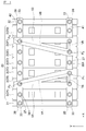
- FIG. 1 is a front view showing an assembled battery in the first embodiment of the present invention.
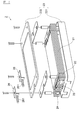
- FIG. 2 is an exploded perspective view showing the battery module in the first embodiment of the present invention.
- FIG. 3 is a partially exploded perspective view showing the assembled battery in the first embodiment of the present invention.
- FIG. 4 is a front view showing a first modification of the reinforcing member in the first embodiment of the present invention.
- FIG. 5 is a front view showing a second modification of the reinforcing member in the first embodiment of the present invention.
- FIG. 6 is a front view showing a third modification of the reinforcing member in the first embodiment of the present invention.
- FIG. 7 is a front view showing an assembled battery in the second embodiment of the present invention.
- FIG. 8 is a front view showing a first modification of the reinforcing member in the second embodiment of the present invention.
- FIG. 1 is a front view showing an assembled battery 1 in this embodiment
- FIG. 2 is an exploded perspective view showing a battery module 2 in this embodiment
- FIG. 3 is a partially exploded perspective view showing the assembled battery 1 in this embodiment
- 4 to 6 are front views showing first to third modifications of the reinforcing members 51 and 52 in the present embodiment.
- the assembled battery 1 of the present embodiment includes a module laminate 20, first and second end plates 31 and 32 provided on the left and right sides of the module laminate 20 in the drawing,
- the first and second connecting members 41 and 42 for connecting and fixing the first and second end plates 31 and 32 and the first and second connecting members 41 and 42 are connected to reinforce the assembled battery 1.
- the module laminate 20 is a laminate composed of a plurality of battery modules 2 stacked in a line in the X direction in the figure, as shown in FIG.
- the battery modules 2 are connected and fixed by through bolts (not shown).
- the assembled battery 1 is configured using seven battery modules 2, but the number of the battery modules 2 constituting the assembled battery 1 is not particularly limited.
- these seven battery modules 2 are also referred to as battery module 2A, battery module 2B, battery module 2C, battery module 2D, battery module 2E, battery module 2F, and battery module 2G in order from the left in FIG.
- the battery module 2 includes, for example, a plurality of unit cells 21 stacked on each other, a spacer 22 interposed between the unit cells 21, and a case that accommodates the unit cells 21 and the spacer 22. 23.
- the cell 21 is a laminated battery such as a lithium ion secondary battery. Although not shown in particular, this single cell 21 has a laminate formed by alternately laminating positive and negative plates through separators, and a laminate film that seals the laminate together with an electrolytic solution. The positive electrode tab connected to the positive electrode plate is led out from one end of the laminate film, and the negative electrode tab connected to the negative electrode plate is led out from the opposite end of the laminate film.
- the unit cell 21 may be composed of a nickel metal hydride battery, a lead battery, or the like.
- the single cells 21 are stacked by alternately reversing the directions of the positive electrode tab and the negative electrode tab of the adjacent single cells 21, and then the single cells 21 are connected in series by directly bonding the positive electrode tab and the negative electrode tab. Connected to. And one end of the said some connected cell 21 is electrically connected with the output terminals 24 and 25 of the positive electrode side and the negative electrode side, respectively.
- the electrical connection relationship of the unit cells 21 is not particularly limited to this.
- such a plurality of unit cells 21 are housed in a case 23 in a state where spacers 22 for maintaining insulation between adjacent unit cells 21 are interposed.
- the case 23 includes a lower case 231 having a box shape and an upper case 232 having a lid shape, and the lower case 231 and the upper case 232 are formed of, for example, an aluminum plate.
- eight unit cells 21 are stacked and housed in the case 23, but the number of the unit cells 21 to be stacked is not particularly limited.
- one unit cell 21 may be housed in the case 23.
- the structure of the case is not particularly limited to the above, and the lower case and the upper case may both be box-shaped and their openings may be combined.
- a bolt support member 26 is attached to the side surface from which the positive and negative terminals 24 and 25 are led out on the outer surface of the upper case 232.
- the bolts 261 provided on the bolt support member 26 are used when first and second connecting members 41 and 42, which will be described later, and first and second reinforcing members 51 and 52 are fastened and fixed with nuts 27. It is done.
- the plurality of battery modules 2 are stacked such that the positive terminals 24 and the negative terminals 25 of adjacent battery modules 2 are alternately arranged. That is, the plurality of battery modules 2 are stacked with their directions reversed alternately.
- the electrical connection relationship between the battery modules 2 is not particularly limited to this.
- the first and second end plates 31 and 32 are plate-like members having the same area as the side surface of the battery module 2 and having a U-shaped cross-sectional shape, It is made of steel such as iron.
- the two end plates 31 and 32 are provided so as to be sandwiched from both sides in the stacking direction of the battery module 2 in the module stack 20, and the first end plate 31 is shown in FIG.
- the second end plate 32 is disposed at the right end in FIG. 1 while being disposed at the left end in the middle.
- Through holes 341 and 342 are formed in the upper and lower ends of the first and second end plates 31 and 32, respectively, as shown in FIG.
- the lower through-hole 341 can be inserted with a bolt 33 used for fixing to a first connecting member 41 described later, and the upper through-hole 342 is connected to a second connecting member 42 described later.
- Bolts 33 used for fixing can be inserted.
- the first and second connecting members 41 and 42 are flat bar-like members provided in the stacking direction of the battery module 2 and connect the first and second end plates 31 and 32 described above, respectively. .
- These 1st and 2nd connection members 41 and 42 have the length comparable as the length of the lamination direction of the battery module 2 in the module laminated body 20, and are formed from steel materials, such as iron.
- the first connecting member 41 is disposed on the lower side in FIG. 1, and the second connecting member 42 is disposed on the upper side in FIG. 1.
- the first connecting member 41 has through holes 431 at both ends in the stacking direction of the battery module 2, and a plurality of (in this example, 7) between the through holes 431 at both ends. ) Through-holes 441 are formed at substantially equal intervals. The plurality of through holes 441 are arranged so as to correspond to the bolts 261 included in the battery modules 2A to 2G, respectively.
- first connecting member 41 The both ends of the first connecting member 41 are fixed to the lower ends of the first and second end plates 31 and 32 using bolts 33 and nuts 28.
- the bolt 33 is inserted into the through hole 431 at one end of the first connecting member 41 and the through hole 341 of the first end plate 31, and the first connecting member 41, the first end plate 31,
- the first connecting member 41 is fixed to the lower end of the first end plate 31 by fastening the bolt 33 and the nut 28 in a state in which the first end plate 31 is sandwiched.
- the bolt 33 is inserted into the through hole 431 at the other end of the first connecting member 41 and the through hole 341 of the second end plate 32, and the first connecting member 41 and the second end plate 32 are connected to each other.
- the first connecting member 41 is fixed to the lower end of the second end plate 32 by fastening the bolt 33 and the nut 28 in a sandwiched state.
- first connecting member 41 is fixed to the battery modules 2A to 2G by bolts 261 and nuts 27 of the battery modules 2A to 2G, respectively.
- the bolts 261 included in the battery modules 2A to 2G are inserted into the through holes 441 of the first connecting member 41, and the bolts 261 are sandwiched between the first connecting members 41.
- the first connecting member 41 is fixed to the battery modules 2A to 2G.
- the nut 27 It is concluded with.
- the second connecting member 42 has through holes 432 formed at both ends in the stacking direction of the battery module 2, and a plurality of (7 in this example) between the through holes 432 at both ends. ) Through-holes 442 are formed at substantially equal intervals. The plurality of through holes 442 are arranged so as to correspond to the bolts 261 included in the battery modules 2A to 2G, respectively.
- the both ends of the second connecting member 42 are fixed to the upper ends of the first and second end plates 31 and 32 using bolts 33 and nuts 28.
- the bolt 33 is inserted into the through hole 432 at one end of the second connecting member 42 and the through hole 342 of the first end plate 31, and the second connecting member 42, the first end plate 31,
- the second connecting member 42 is fixed to the upper end of the first end plate 31 by fastening the bolt 33 and the nut 28 with the pin interposed therebetween.
- the bolt 33 is inserted into the through hole 432 at the other end of the second connecting member 42 and the through hole 342 of the second end plate 32, and the second connecting member 42 and the second end plate 32 are connected to each other.
- the second connecting member 42 is fixed to the upper end of the second end plate 32 by fastening the bolt 33 and the nut 28 in a sandwiched state.
- the second connecting member 42 is also fixed to the battery modules 2A to 2G by bolts 261 and nuts 27 of the battery modules 2A to 2G, respectively.
- the bolts 261 included in the battery modules 2A to 2G are inserted into the through holes 442 of the second connecting member 42, respectively, and the bolts 261 are sandwiched between the second connecting members 42.
- the second connecting member 42 is fixed to the battery modules 2A to 2G.
- the nut 27 It is concluded with.
- first and second connecting members 41 and 42 are configured such that the battery modules 2A and 2G arranged at both ends of the plurality of battery modules 2 have at least one bolt 261, respectively.
- the first and second end plates 31 and 32 may be omitted as long as they are fixed to the members 41 and 42, and the number of battery modules 2 fixed to the first and second connecting members 41 and 42 is as follows. There is no particular limitation. For example, all of the battery modules 2A to 2G may be fixed to the first and second connecting members 41 and 42, or every other battery module 2 is fixed to the first and second connecting members 41 and 42. May be.
- first and second connecting members 41 and 42 connect the first and second end plates 31 and 32, respectively, the bolts 261 of the battery modules 2A to 2G may be omitted.
- the first and second reinforcing members 51 and 52 are members that connect the first connecting member 41 and the second connecting member 42, and are formed from a steel material such as iron having a flat plate shape. Is done.
- through holes 541 and 542 into which the bolts 261 of the battery module 2 can be inserted are provided at the upper and lower ends of the first and second reinforcing members 51 and 52.
- the first and second reinforcing members 51 and 52 are fixed to the first and second connecting members 41 and 42, respectively.
- the battery module 2 is combined with the through hole 441 of the first connecting member 41 as shown in FIG. 3.
- the first and second reinforcing members 51 and 52 are respectively fixed to the first connecting member 41 by inserting the bolt 261 and fastening the bolt 261 and the nut 27.
- the bolts 261 of the battery module 2 are inserted into the upper through holes 542 of the first and second reinforcing members 51 and 52 together with the through holes 442 of the second connecting member 42, By fastening the nut 27, the first and second reinforcing members 51 and 52 are fixed to the second connecting member 42, respectively.
- first and second connecting members 41 and 42 and the first and second reinforcing members 51 and 52 described above are also provided on the back side of the module laminate 20. .
- the first and second reinforcing members 51 and 52 are fixed to the first and second connecting members 41 and 42 using the bolts 261 provided in the battery module 2. It is not particularly limited to this. For example, you may fix the 1st and 2nd reinforcement members 51 and 52 and the 1st and 2nd connection members 41 and 42 using the volt
- the lower end (first fixing point P 1 ) of the first reinforcing member 51 is fixed by the bolt 261 included in the battery module 2C, and the upper end of the first reinforcing member 51 (Second fixing point P 2 ) is fixed by a bolt 261 included in the battery module 2B.
- the lower end (third fixing point P 3 ) of the second reinforcing member 52 is fixed by a bolt 261 included in the battery module 2E, and the upper end (fourth fixing point P 4 ) of the second reinforcing member 52 is fixed.
- the battery module 2F is fixed with bolts 261.
- the first reinforcing member 51 and the second reinforcing member 52 are attached so that they are separated from each other from the lower side to the upper side in FIG. That is, the direction of the X-direction component vector (hereinafter referred to as vector Va) of the vector (hereinafter referred to as vector VA) from the first fixed point P 1 to the second fixed point P 2 , and the third vector from the fixed point P 3 toward the fourth fixed point P 4 in the X-direction component vector (hereinafter, referred to as vector VB.) and orientation (hereinafter, referred to as a vector Vb.), it has become the opposite.
- vector Va the direction of the X-direction component vector
- vector VB the vector from the fixed point P 3 toward the fourth fixed point P 4 in the X-direction component vector
- orientation hereinafter, referred to as a vector Vb.
- the configuration is not particularly limited to the above as long as the direction of the vector Va is opposite to the direction of the vector Vb.
- the length which the 1st and 2nd reinforcement members 51 and 52 have is suitably adjusted according to the fixed position of those upper ends and lower ends.
- the first reinforcing member 51 is fixed by the bolts 261 of the adjacent battery modules 2B and 2C. However, the first reinforcing member 51 straddles the battery module 2C by using the bolts 261 of the battery module 2B and the bolts 261 of the battery module 2D.
- the first reinforcing member 51 may be fixed.
- the first reinforcing member 51 may be fixed across two or more battery modules 2, and the second reinforcing member 52 may be fixed across one or more battery modules 2 at this time. .
- the first and second reinforcing members 51 and 52 are attached so that they are separated from each other from the lower side to the upper side in FIG. 1, but are not particularly limited thereto.
- the first reinforcing member 51 has a substantially triangular shape, and a total of three by one of the two bolts 261 included in the battery module 2B and the bolt 261 included in the battery module 2C.
- the first reinforcing member 51 may be fixed to the first and second connecting members 41 and 42 at one fixing point.
- the second reinforcing member 52 has a substantially triangular shape, and the second reinforcing member 52 has a total of three fixing points by one of the bolts 261 included in the battery module 2E and two bolts 261 included in the battery module 2F.
- the reinforcing member 52 may be fixed to the first and second connecting members 41 and 42.
- first or second reinforcing members 51 and 52 may be fixed to the first and second connecting members 41 and 42 at four or more fixing points.
- connection members 41 and 42 for fixing two end plates 31 and 32 positioned at both ends of the plurality of stacked battery modules 2A to 2G are provided, and the two connection members 41, 42, first and second reinforcing members 51 and 52 that reinforce the assembled battery 1 by connecting 42 are provided.
- the direction of the component vector Va along the X direction in the vector VA is opposite to the direction of the component vector Vb along the X direction in the vector VB. It has become. Therefore, even when an external force is applied along the stacking direction of the battery modules 2A to 2G in the assembled battery 1, it is possible to prevent the plurality of battery modules 2 from being tilted.
- the first auxiliary member 51 applies the external force F. It has a vector Va in the opposite direction.
- the external force F is offset by the presence of the first auxiliary member 51, so that the battery module 2A is tilted by the external force F, and the plurality of battery modules 2B to 2G are prevented from tilting in conjunction with this.
- the battery modules 2A to 2G can be held stably.
- the first and second connecting members 41 and 42 and the first and second reinforcing members 51 and 52 are fixed by using bolts 261 attached to the battery modules 2A to 2G. . Accordingly, since the battery modules 2A to 2G are directly fixed to the connecting members 41 and 42 and the reinforcing members 51 and 52, the battery modules 2A to 2G can be held more stably.
- one of the upper end and the lower end of the first reinforcing member 51 is located at the same position as one of the upper end or the lower end of the second reinforcing member 52 (in this example, the bolt 261 included in the battery module 2D).
- the first and second reinforcing members 51 and 52 may be fixed to the first and second connecting members 41 and 42 at a total of three fixing points.
- the vector Va in the first reinforcing member 51 and the vector Vb in the second reinforcing member 52 can be efficiently ensured. It is possible to prevent the battery module 2 from being tilted by an external force, and to stably hold the battery modules 2A to 2G.
- first and second reinforcing members 51 and 52 may be constituted by a single reinforcing member 53 as shown in FIG.
- the number of parts constituting the assembled battery 1 can be reduced, and workability when assembling the assembled battery 1 can be improved.
- the vector Va and the vector Vb can be efficiently secured by the reinforcing member 53, so that the battery module 2 can be prevented from being tilted by an external force.
- the modules 2A to 2G can be stably held.
- the direction of the vector Va in the present embodiment corresponds to an example of the direction of the component along the stacking direction of the battery modules in the vector having the first fixed point of the present invention as the start point and the second fixed point as the end point.
- the direction of the vector Vb in the present embodiment corresponds to an example of the direction of the component along the stacking direction of the battery modules in the vector having the third fixed point of the present invention as the start point and the fourth fixed point as the end point
- the bolt 261 in the present embodiment corresponds to an example of the first bolt of the present invention and an example of the second bolt of the present invention.
- FIG. 7 is a front view showing the assembled battery 1B in the present embodiment
- FIG. 8 is a front view showing a modification of the reinforcing members 51B and 52B in the present embodiment.
- the assembled battery 1B in the second embodiment does not have the second connecting member 42, and the upper ends of the first and second reinforcing members 51B and 52B are fixed to the first or second end plates 31 and 32, respectively. Since it is the same as that of 1st Embodiment mentioned above except the point currently performed, only the part which is different from 1st Embodiment is demonstrated, and the part which is the same as 1st Embodiment is the same as 1st Embodiment. The description will be omitted.
- the first and second reinforcing members 51B and 52B are members that connect the first connecting member 41 and the first or second end plates 31 and 32, and have a flat plate shape. It is formed from steel materials.
- a through hole into which a bolt 33 used for fixing to the end plates 31 and 32 can be inserted is provided at the upper end of the first and second reinforcing members 51B and 52B, and at the lower end.
- a through hole into which the bolt 261 included in the battery module 2 can be inserted is provided.
- the upper ends of the first and second reinforcing members 51B and 52B are fixed to the upper ends of the end plates 31 and 32 by using bolts 33 and nuts 28, respectively.
- the bolt 33 is inserted into the through hole at the upper end in FIG. 7 in the first reinforcing member 51B and the through hole 342 in the first end plate 31, and the first reinforcing member 51B and the first reinforcing member 51B are connected to the first reinforcing member 51B.
- the first reinforcing member 51B is fixed to the upper end of the first end plate 31 by fastening the bolt 33 and the nut 28 with the end plate 31 interposed therebetween.
- the bolts 33 are inserted into the through holes at the upper end in FIG. 7 in the second reinforcing member 52B and the through holes 342 in the second end plate 32, and the second reinforcing member 52B and the second end plate are inserted.
- the second reinforcing member 52 ⁇ / b> B is fixed to the upper end of the second end plate 32 by fastening the bolt 33 and the nut 28 with the pin 32 interposed therebetween.
- first and second reinforcing members 51B and 52B are fixed to the first connecting member 41 using bolts 261 included in the battery module 2.
- the bolts 261 of the battery module 2 are inserted into the through holes provided at the lower ends of the first and second reinforcing members 51B and 52B together with the through holes 441 of the first connecting member 41, respectively.
- the first and second reinforcing members 51B and 52B are fixed to the first connecting member 41 by fastening the bolt 261 and the nut 27, respectively.
- first connecting member 41 and the first and second reinforcing members 51B and 52B described above are also provided on the back side of the module laminate 20.
- the lower end (first fixing point P 1 ) of the first reinforcing member 51B is fixed with the bolt 261 included in the battery module 2B, and the second reinforcing member 52B.
- the lower end (third fixing point P 3) are bolted 261 having the battery module 2F.
- the upper end (second fixing point P 2 ) of the first reinforcing member 51B is fixed to the upper end of the first end plate 31, and the upper end (first of the second reinforcing member 52B) 4 fixing point P 4 ) is fixed to the upper end of the second end plate 32.
- the direction of the X direction component vector Va of the vector VA from the first fixed point P 1 towards the second fixed point P 2, the fourth fixed point from the third fixed point P 3 and orientation of the X direction component vector Vb of the vector VB toward the P 4 is made opposite.
- the plurality of battery modules 2 can be prevented from tilting, and the battery modules 2A to 2G can be stably held. be able to.
- the front surface of the assembled battery 1 ⁇ / b> B in this embodiment connects the first and second end plates 31 and 32 using only the first connecting member 41. For this reason, the number of parts constituting the assembled battery 1B can be reduced, the workability at the time of assembling the assembled battery 1B can be improved, and the assembled battery 1B can be reduced in weight.
- the first connecting member 41 and the first and second reinforcing members 51B and 52B are fixed using the bolts 261 attached to the battery modules 2A to 2G. Accordingly, since the battery modules 2A to 2G are directly fixed to the connecting member 41 and the reinforcing members 51B and 52B, the battery modules 2A to 2G can be held more stably.
- the first and second reinforcing members 51B and 52B may be fixed to the first connecting member 41 and the first and second end plates 31 and 32 at a total of three fixing points.
- the vector Va in the first reinforcing member 51B and the vector Vb in the second reinforcing member 52B can be efficiently ensured. It is possible to prevent the battery module 2 from being tilted by an external force, and to stably hold the battery modules 2A to 2G.
- the direction of the vector Va in the present embodiment corresponds to an example of the direction of the component along the stacking direction of the battery modules in the vector having the first fixed point of the present invention as the start point and the second fixed point as the end point.
- the direction of the vector Vb in the present embodiment corresponds to an example of the direction of the component along the stacking direction of the battery modules in the vector having the third fixed point of the present invention as the start point and the fourth fixed point as the end point
- the bolt 261 in the present embodiment corresponds to an example of the bolt of the present invention.
- the configuration described in the first embodiment (the configuration including the two connecting members 41 and 42 and the two reinforcing members 51 and 52) is provided on one surface of the module stacked body 20, and the module stacking is performed.
- the configuration described in the second embodiment (a configuration including one connecting member 41 and two reinforcing members 51B and 52B) may be provided on the other surface of the body 20.
Landscapes
- Chemical & Material Sciences (AREA)
- Chemical Kinetics & Catalysis (AREA)
- Electrochemistry (AREA)
- General Chemical & Material Sciences (AREA)
- Engineering & Computer Science (AREA)
- Manufacturing & Machinery (AREA)
- Battery Mounting, Suspending (AREA)
Abstract
Description
本出願は、2012年9月18日に出願された日本国特許出願の特願2012―204139に基づく優先権を主張するものであり、文献の参照による組み込みが認められる指定国については、上記の出願に記載された内容を参照により本出願に組み込み、本出願の記載の一部とする。
図1は本実施形態における組電池1を示す正面図であり、図2は本実施形態における電池モジュール2を示す分解斜視図であり、図3は本実施形態における組電池1を示す部分分解斜視図であり、図4~図6は本実施形態における補強部材51、52の第1~第3変形例を示す正面図である。
図7は本実施形態における組電池1Bを示す正面図であり、図8は本実施形態における補強部材51B、52Bの変形例を示す正面図である。第2実施形態における組電池1Bは、第2の連結部材42を有しておらず、第1及び第2の補強部材51B、52Bの上端が第1又は第2のエンドプレート31、32と固定されている点以外は、上述した第1実施形態と同様であるので、第1実施形態と相違する部分についてのみ説明し、第1実施形態と同一である部分については、第1実施形態と同一の符号を付して説明を省略する。
2・・・電池モジュール
261・・・ボルト
31・・・第1のエンドプレート
32・・・第2のエンドプレート
41・・・第1の連結部材
42・・・第2の連結部材
51、51B・・・第1の補強部材
52、52B・・・第2の補強部材
53・・・補強部材
Claims (7)
- 積層された複数の電池モジュールを有するモジュール積層体と、
前記複数の電池モジュールの積層を保持するために、前記複数の電池モジュールの積層方向に延在している第1の連結部材と、
前記モジュール積層体において前記第1の連結部材と同一面に設けられ、前記複数の電池モジュールの積層を保持するために、前記複数の電池モジュールの積層方向に延在している第2の連結部材と、
前記第1の連結部材に第1の固定点で固定されていると共に、前記第2の連結部材に第2の固定点で固定されている第1の補強部材と、
前記第1の連結部材に第3の固定点で固定されていると共に、前記第2の連結部材に第4の固定点で固定されている第2の補強部材と、を備え、
前記第1の固定点を始点とし、前記第2の固定点を終点とするベクトルにおける前記電池モジュールの積層方向に沿った成分の向きと、
前記第3の固定点を始点とし、前記第4の固定点を終点とするベクトルにおける前記電池モジュールの積層方向に沿った成分の向きと、が反対であることを特徴とする組電池。 - 請求項1に記載の組電池であって、
前記第1の補強部材及び前記第2の補強部材は、単一の部材から構成されていることを特徴とする組電池。 - 請求項1又は請求項2に記載の組電池であって、
前記第1の固定点と前記第3の固定点とは同一の点であり、又は、前記第2の固定点と前記第4の固定点とは同一の点であることを特徴とする組電池。 - 請求項1~3の何れかに記載の組電池であって、
前記電池モジュールは、
前記第1の連結部材に向かって突出する第1のボルトと、
前記第2の連結部材に向かって突出する第2のボルトと、を有し、
前記第1のボルトは、前記第1の連結部材と、前記第1の補強部材及び前記第2の補強部材の少なくとも一方と、を固定し、
前記第2のボルトは、前記第2の連結部材と、前記第1の補強部材及び前記第2の補強部材の少なくとも一方と、を固定していることを特徴とする組電池。 - 積層された複数の電池モジュールを有するモジュール積層体と、
前記モジュール積層体の一端に設けられた第1のエンドプレートと、
前記モジュール積層体の他端に設けられた第2のエンドプレートと、
前記第1のエンドプレートと、前記第2のエンドプレートとを固定する連結部材と、
前記連結部材に第1の固定点で固定されていると共に、前記第1のエンドプレートに第2の固定点で固定されている第1の補強部材と、
前記連結部材に第3の固定点で固定されていると共に、前記第2のエンドプレートに第4の固定点で固定されている第2の補強部材と、を備え、
前記第1の固定点を始点とし、前記第2の固定点を終点とするベクトルにおける前記電池モジュールの積層方向に沿った成分の向きと、
前記第3の固定点を始点とし、前記第4の固定点を終点とするベクトルにおける前記電池モジュールの積層方向に沿った成分の向きと、が反対であることを特徴とする組電池。 - 請求項5に記載の組電池であって、
前記第1の固定点と前記第3の固定点とは同一の点であることを特徴とする組電池。 - 請求項5又は請求項6に記載の組電池であって、
前記電池モジュールは、前記連結部材に向かって突出するボルトを有し、
前記ボルトは、前記連結部材と、前記第1の補強部材及び前記第2の補強部材の少なくとも一方と、を固定していることを特徴とする組電池。
Priority Applications (5)
| Application Number | Priority Date | Filing Date | Title |
|---|---|---|---|
| US14/423,873 US9742025B2 (en) | 2012-09-18 | 2013-08-09 | Battery pack |
| JP2014536675A JP5880722B2 (ja) | 2012-09-18 | 2013-08-09 | 組電池 |
| EP13839998.5A EP2899773B1 (en) | 2012-09-18 | 2013-08-09 | Assembled battery |
| KR1020157003525A KR101722344B1 (ko) | 2012-09-18 | 2013-08-09 | 조전지 |
| CN201380048587.7A CN104641489B (zh) | 2012-09-18 | 2013-08-09 | 电池组 |
Applications Claiming Priority (2)
| Application Number | Priority Date | Filing Date | Title |
|---|---|---|---|
| JP2012-204139 | 2012-09-18 | ||
| JP2012204139 | 2012-09-18 |
Publications (1)
| Publication Number | Publication Date |
|---|---|
| WO2014045756A1 true WO2014045756A1 (ja) | 2014-03-27 |
Family
ID=50341080
Family Applications (1)
| Application Number | Title | Priority Date | Filing Date |
|---|---|---|---|
| PCT/JP2013/071618 Ceased WO2014045756A1 (ja) | 2012-09-18 | 2013-08-09 | 組電池 |
Country Status (6)
| Country | Link |
|---|---|
| US (1) | US9742025B2 (ja) |
| EP (1) | EP2899773B1 (ja) |
| JP (1) | JP5880722B2 (ja) |
| KR (1) | KR101722344B1 (ja) |
| CN (1) | CN104641489B (ja) |
| WO (1) | WO2014045756A1 (ja) |
Cited By (3)
| Publication number | Priority date | Publication date | Assignee | Title |
|---|---|---|---|---|
| JP2021026875A (ja) * | 2019-08-03 | 2021-02-22 | 三洋電機株式会社 | 電源装置とこの電源装置を備える電動車両及び蓄電装置 |
| JP2021157952A (ja) * | 2020-03-27 | 2021-10-07 | 本田技研工業株式会社 | 蓄電装置 |
| EP4358252A1 (en) | 2022-10-20 | 2024-04-24 | Prime Planet Energy & Solutions, Inc. | Battery module |
Families Citing this family (3)
| Publication number | Priority date | Publication date | Assignee | Title |
|---|---|---|---|---|
| US11189877B2 (en) * | 2019-01-11 | 2021-11-30 | Toyota Jidosha Kabushiki Kaisha | Battery pack and vehicle for mounting the same |
| KR102835514B1 (ko) * | 2020-04-09 | 2025-07-16 | 주식회사 엘지에너지솔루션 | 배터리 모듈, 그것을 포함하는 배터리 팩, 및 자동차 |
| KR102432538B1 (ko) * | 2020-11-04 | 2022-08-16 | 주식회사 성우하이텍 | 배터리 모듈 및 그 제조 방법 |
Citations (8)
| Publication number | Priority date | Publication date | Assignee | Title |
|---|---|---|---|---|
| JPS6130963U (ja) * | 1984-07-30 | 1986-02-25 | 新神戸電機株式会社 | 蓄電池耐震架台装置 |
| JP2001236937A (ja) * | 1999-12-15 | 2001-08-31 | Toyota Motor Corp | 電池パック |
| JP2007299544A (ja) * | 2006-04-27 | 2007-11-15 | Sanyo Electric Co Ltd | パック電池 |
| JP2009032550A (ja) * | 2007-07-27 | 2009-02-12 | Sanyo Electric Co Ltd | 電源装置 |
| WO2011096677A2 (ko) * | 2010-02-04 | 2011-08-11 | 주식회사 엘지화학 | 보강부재를 포함하고 있는 전지팩 |
| JP2012018915A (ja) | 2010-07-06 | 2012-01-26 | Sb Limotive Co Ltd | 電池モジュール |
| WO2012026224A1 (ja) * | 2010-08-24 | 2012-03-01 | 日本碍子株式会社 | 集合電池用架台 |
| JP2012146588A (ja) * | 2011-01-14 | 2012-08-02 | Hitachi Vehicle Energy Ltd | 電池モジュール |
Family Cites Families (5)
| Publication number | Priority date | Publication date | Assignee | Title |
|---|---|---|---|---|
| JP3271495B2 (ja) * | 1995-10-24 | 2002-04-02 | 松下電器産業株式会社 | 組蓄電池 |
| JP5663937B2 (ja) | 2009-04-24 | 2015-02-04 | 日産自動車株式会社 | 電池モジュールの位置決め方法及び組電池の組付治具 |
| US8592068B2 (en) * | 2009-04-24 | 2013-11-26 | Nissan Motor Co., Ltd. | Battery pack |
| US20110165451A1 (en) | 2010-01-05 | 2011-07-07 | Myung-Chul Kim | Battery pack |
| JP5666274B2 (ja) * | 2010-12-04 | 2015-02-12 | 三洋電機株式会社 | 組電池及びこれを備える車両 |
-
2013
- 2013-08-09 JP JP2014536675A patent/JP5880722B2/ja active Active
- 2013-08-09 EP EP13839998.5A patent/EP2899773B1/en active Active
- 2013-08-09 KR KR1020157003525A patent/KR101722344B1/ko active Active
- 2013-08-09 WO PCT/JP2013/071618 patent/WO2014045756A1/ja not_active Ceased
- 2013-08-09 US US14/423,873 patent/US9742025B2/en active Active
- 2013-08-09 CN CN201380048587.7A patent/CN104641489B/zh active Active
Patent Citations (8)
| Publication number | Priority date | Publication date | Assignee | Title |
|---|---|---|---|---|
| JPS6130963U (ja) * | 1984-07-30 | 1986-02-25 | 新神戸電機株式会社 | 蓄電池耐震架台装置 |
| JP2001236937A (ja) * | 1999-12-15 | 2001-08-31 | Toyota Motor Corp | 電池パック |
| JP2007299544A (ja) * | 2006-04-27 | 2007-11-15 | Sanyo Electric Co Ltd | パック電池 |
| JP2009032550A (ja) * | 2007-07-27 | 2009-02-12 | Sanyo Electric Co Ltd | 電源装置 |
| WO2011096677A2 (ko) * | 2010-02-04 | 2011-08-11 | 주식회사 엘지화학 | 보강부재를 포함하고 있는 전지팩 |
| JP2012018915A (ja) | 2010-07-06 | 2012-01-26 | Sb Limotive Co Ltd | 電池モジュール |
| WO2012026224A1 (ja) * | 2010-08-24 | 2012-03-01 | 日本碍子株式会社 | 集合電池用架台 |
| JP2012146588A (ja) * | 2011-01-14 | 2012-08-02 | Hitachi Vehicle Energy Ltd | 電池モジュール |
Non-Patent Citations (1)
| Title |
|---|
| See also references of EP2899773A4 |
Cited By (5)
| Publication number | Priority date | Publication date | Assignee | Title |
|---|---|---|---|---|
| JP2021026875A (ja) * | 2019-08-03 | 2021-02-22 | 三洋電機株式会社 | 電源装置とこの電源装置を備える電動車両及び蓄電装置 |
| JP7366630B2 (ja) | 2019-08-03 | 2023-10-23 | 三洋電機株式会社 | 電源装置とこの電源装置を備える電動車両及び蓄電装置 |
| JP2021157952A (ja) * | 2020-03-27 | 2021-10-07 | 本田技研工業株式会社 | 蓄電装置 |
| JP7493365B2 (ja) | 2020-03-27 | 2024-05-31 | 本田技研工業株式会社 | 蓄電装置 |
| EP4358252A1 (en) | 2022-10-20 | 2024-04-24 | Prime Planet Energy & Solutions, Inc. | Battery module |
Also Published As
| Publication number | Publication date |
|---|---|
| CN104641489B (zh) | 2017-09-26 |
| KR20150038036A (ko) | 2015-04-08 |
| CN104641489A (zh) | 2015-05-20 |
| US20150270570A1 (en) | 2015-09-24 |
| JPWO2014045756A1 (ja) | 2016-08-18 |
| EP2899773B1 (en) | 2018-01-03 |
| EP2899773A1 (en) | 2015-07-29 |
| JP5880722B2 (ja) | 2016-03-09 |
| EP2899773A4 (en) | 2015-12-16 |
| US9742025B2 (en) | 2017-08-22 |
| KR101722344B1 (ko) | 2017-03-31 |
Similar Documents
| Publication | Publication Date | Title |
|---|---|---|
| JP5908706B2 (ja) | バッテリモジュール | |
| JP5544931B2 (ja) | ラミネートセル電池構造体 | |
| JP5880722B2 (ja) | 組電池 | |
| JP5657273B2 (ja) | 積層型電池、電池モジュール及び積層型電池の製造方法 | |
| US9929427B2 (en) | Battery module having reinforcing barrier with metal member | |
| KR101249184B1 (ko) | 조전지 및 조전지의 제조 방법 | |
| CN106605317B (zh) | 组电池 | |
| JP2017196961A (ja) | 車両のバッテリ搭載構造 | |
| JP2012519362A (ja) | 電気的エネルギー貯蔵セルおよびセルブロック、電気的エネルギー貯蔵装置ならびに当該装置を有する車両 | |
| JP2011198660A (ja) | 電池パック | |
| WO2013132978A1 (ja) | 組電池 | |
| JP5619076B2 (ja) | 蓄電装置 | |
| WO2013021592A1 (ja) | 電池パック | |
| WO2014010419A1 (ja) | 組電池 | |
| CN102714294A (zh) | 电池、及具备该电池的装置 | |
| EP2490277A1 (en) | Battery Module | |
| JP2016192335A (ja) | 電池パック | |
| JP2017111914A (ja) | 電池パック | |
| JP2013187104A (ja) | 電池モジュール及び扁平型電池セル | |
| JPWO2019181411A1 (ja) | 電池モジュールおよび電池パック | |
| US20130149591A1 (en) | Secondary battery module | |
| WO2018155090A1 (ja) | 組電池及び組電池用バスバ | |
| JP4029819B2 (ja) | 組電池 | |
| JP2022147509A (ja) | 電池パック | |
| JP2022154883A (ja) | 電池パック |
Legal Events
| Date | Code | Title | Description |
|---|---|---|---|
| 121 | Ep: the epo has been informed by wipo that ep was designated in this application |
Ref document number: 13839998 Country of ref document: EP Kind code of ref document: A1 |
|
| ENP | Entry into the national phase |
Ref document number: 2014536675 Country of ref document: JP Kind code of ref document: A |
|
| ENP | Entry into the national phase |
Ref document number: 20157003525 Country of ref document: KR Kind code of ref document: A |
|
| WWE | Wipo information: entry into national phase |
Ref document number: 14423873 Country of ref document: US |
|
| NENP | Non-entry into the national phase |
Ref country code: DE |