WO2014045720A1 - 音響発生器、音響発生装置及び電子機器 - Google Patents
音響発生器、音響発生装置及び電子機器 Download PDFInfo
- Publication number
- WO2014045720A1 WO2014045720A1 PCT/JP2013/070822 JP2013070822W WO2014045720A1 WO 2014045720 A1 WO2014045720 A1 WO 2014045720A1 JP 2013070822 W JP2013070822 W JP 2013070822W WO 2014045720 A1 WO2014045720 A1 WO 2014045720A1
- Authority
- WO
- WIPO (PCT)
- Prior art keywords
- vibrating body
- sound
- piezoelectric vibration
- vibration element
- exciter
- Prior art date
- Legal status (The legal status is an assumption and is not a legal conclusion. Google has not performed a legal analysis and makes no representation as to the accuracy of the status listed.)
- Ceased
Links
Images






Classifications
-
- H—ELECTRICITY
- H04—ELECTRIC COMMUNICATION TECHNIQUE
- H04R—LOUDSPEAKERS, MICROPHONES, GRAMOPHONE PICK-UPS OR LIKE ACOUSTIC ELECTROMECHANICAL TRANSDUCERS; ELECTRIC HEARING AIDS; PUBLIC ADDRESS SYSTEMS
- H04R17/00—Piezoelectric transducers; Electrostrictive transducers
-
- H—ELECTRICITY
- H04—ELECTRIC COMMUNICATION TECHNIQUE
- H04R—LOUDSPEAKERS, MICROPHONES, GRAMOPHONE PICK-UPS OR LIKE ACOUSTIC ELECTROMECHANICAL TRANSDUCERS; ELECTRIC HEARING AIDS; PUBLIC ADDRESS SYSTEMS
- H04R1/00—Details of transducers, loudspeakers or microphones
- H04R1/20—Arrangements for obtaining desired frequency or directional characteristics
- H04R1/22—Arrangements for obtaining desired frequency or directional characteristics for obtaining desired frequency characteristic only
- H04R1/28—Transducer mountings or enclosures modified by provision of mechanical or acoustic impedances, e.g. resonator, damping means
- H04R1/2869—Reduction of undesired resonances, i.e. standing waves within enclosure, or of undesired vibrations, i.e. of the enclosure itself
- H04R1/2876—Reduction of undesired resonances, i.e. standing waves within enclosure, or of undesired vibrations, i.e. of the enclosure itself by means of damping material, e.g. as cladding
- H04R1/288—Reduction of undesired resonances, i.e. standing waves within enclosure, or of undesired vibrations, i.e. of the enclosure itself by means of damping material, e.g. as cladding for loudspeaker transducers
-
- H—ELECTRICITY
- H04—ELECTRIC COMMUNICATION TECHNIQUE
- H04R—LOUDSPEAKERS, MICROPHONES, GRAMOPHONE PICK-UPS OR LIKE ACOUSTIC ELECTROMECHANICAL TRANSDUCERS; ELECTRIC HEARING AIDS; PUBLIC ADDRESS SYSTEMS
- H04R7/00—Diaphragms for electromechanical transducers; Cones
- H04R7/02—Diaphragms for electromechanical transducers; Cones characterised by the construction
- H04R7/04—Plane diaphragms
- H04R7/06—Plane diaphragms comprising a plurality of sections or layers
- H04R7/08—Plane diaphragms comprising a plurality of sections or layers comprising superposed layers separated by air or other fluid
Definitions
- the disclosed embodiment relates to an acoustic generator, an acoustic generator, and an electronic device.
- an acoustic generator represented by a piezoelectric speaker can be used as a small and thin speaker.
- a sound generator can be used as a speaker incorporated in an electronic device such as a mobile phone or a thin television.
- an acoustic generator for example, there is one including a vibrating body and a piezoelectric vibrating element provided on the vibrating body (see, for example, Patent Document 1). This is a configuration in which a vibrating body is vibrated by a piezoelectric vibration element, and a sound is generated using a resonance phenomenon of the vibrating body.
- One aspect of the embodiment has been made in view of the above, and reduces the difference between the resonance peak and the dip in the frequency characteristic of the sound pressure to suppress the frequency fluctuation of the sound pressure as much as possible, thereby improving the sound quality.
- An object is to provide a sound generator, a sound generator, and an electronic device that can be improved.
- the acoustic generator includes a vibrating body and an exciter provided on the vibrating body, and the exciter has a convex portion or a concave portion on a surface on the vibrating body side.
- the exciter has a convex portion or a concave portion on the surface on the vibrating body side, so that the difference between the resonance peak and the dip in the frequency characteristic of the sound pressure can be reduced. Can be suppressed as much as possible, and the sound quality can be improved.
- FIG. 1A is a schematic plan view of the sound generator according to the first embodiment.
- 1B is a cross-sectional view taken along line A-A ′ of FIG. 1A.
- 1C is a cross-sectional view taken along line B-B ′ of FIG. 1A.
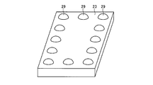
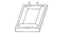
- FIG. 2 is a schematic diagram illustrating an arrangement example of convex portions in the piezoelectric vibration element illustrated in FIG. 1.
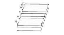
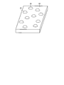
- FIG. 3 is a schematic diagram illustrating another arrangement example of the convex portions in the piezoelectric vibration element illustrated in FIG. 1.
- FIG. 4 is a schematic diagram illustrating another arrangement example of the convex portions in the piezoelectric vibration element illustrated in FIG. 1.
- FIG. 1A is a schematic plan view of the sound generator according to the first embodiment.
- 1B is a cross-sectional view taken along line A-A ′ of FIG. 1A.
- 1C is a cross-sectional view taken along line B-B ′ of FIG. 1A.
- FIG. 2 is
- FIG. 5 is a schematic diagram showing another arrangement example of the convex portions in the piezoelectric vibration element shown in FIG. 1.
- FIG. 6 is a schematic diagram illustrating another arrangement example of the convex portions in the piezoelectric vibration element illustrated in FIG. 1.
- FIG. 7 is a block diagram of the sound generator.
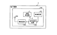
- FIG. 8 is a block diagram of an electronic device.
- FIG. 9 is a cross-sectional view taken along line B-B ′ of FIG. 1A showing the sound generator according to the second embodiment.
- FIG. 10 is a schematic diagram illustrating an example of the arrangement of the recesses in the piezoelectric vibration element illustrated in FIG. 9.
- FIG. 11 is a schematic diagram illustrating another arrangement example of the recesses in the piezoelectric vibration element illustrated in FIG. 9.
- FIG. 10 is a schematic diagram illustrating an example of the arrangement of the recesses in the piezoelectric vibration element illustrated in FIG. 9.
- FIG. 12 is a schematic diagram illustrating an arrangement example of convex portions and concave portions in the piezoelectric vibration element constituting the acoustic generator according to the third embodiment.
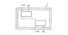
- FIG. 13A is a schematic plan view of an acoustic generator according to a modification of each embodiment.
- 13B is a cross-sectional view taken along line C-C ′ of FIG. 13A.
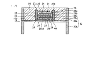
- FIG. 1A is a schematic plan view of the sound generator 1 according to the first embodiment viewed from a direction perpendicular to the main surface of the vibrating body 10,
- FIG. 1B is a cross-sectional view taken along line AA ′ in FIG. 1A, and
- FIG. 1B is a sectional view taken along line BB ′ in FIG. 1A.
- the sound generator 1 is shown expanded and deformed in the vertical direction.
- an acoustic generator 1 includes a vibrating body 10, a piezoelectric vibrating element 20 that is an example of an exciter that receives an electric signal and vibrates, and a frame. 30.
- Such an acoustic generator 1 is called a so-called piezoelectric speaker, and generates a sound pressure using a resonance phenomenon of the vibrating body 10 itself.
- the vibrating body 10 can be formed using various materials such as resin, metal, and paper.
- the thin plate-like vibrating body 10 can be formed of a resin film such as polyethylene, polyimide, or polypropylene having a thickness of 10 to 200 ⁇ m. Since the resin film is a material having a lower elastic modulus and mechanical Q value than a metal plate or the like, the vibrating body 10 is made of a resin film to bend and vibrate the vibrating body 10 with a large amplitude so that the sound pressure is reduced. It is possible to reduce the difference between the resonance peak and the dip by widening the width of the resonance peak and reducing the height in the frequency characteristics.
- the piezoelectric vibration element 20 is a bimorph type laminated piezoelectric vibration element.
- the piezoelectric vibration element 20 includes a laminated body 21, surface electrode layers 22 and 23 formed on the upper and lower surfaces of the laminated body 21, and an external surface formed on the side surface where the end face of the internal electrode layer 24 of the laminated body 21 is exposed. Electrodes 25 and 26 are provided. Then, lead terminals 27 a and 27 b are connected to the external electrodes 25 and 26.
- the laminate 21 is formed by alternately laminating four piezoelectric layers 28a, 28b, 28c, 28d made of ceramics and three internal electrode layers 24.
- the piezoelectric vibration element 20 has a rectangular main surface on the upper surface side and the lower surface side, and the piezoelectric layers 28a and 28b and the piezoelectric layers 28c and 28d are polarized in different directions in the thickness direction, The piezoelectric layers 28b and 28c are polarized in the same direction.
- the piezoelectric vibration element 20 when a voltage is applied to the piezoelectric vibration element 20 via the lead terminals 27a and 27b, for example, the lower surface side of the piezoelectric vibration element 20, in other words, the piezoelectric layers 28c and 28d on the vibration body 10 side contract, while the upper surface The piezoelectric layers 28a and 28b on the side are deformed so as to extend.
- the piezoelectric layers 28a and 28b on the upper surface side of the piezoelectric vibration element 20 and the piezoelectric layers 28c and 28d on the lower surface side exhibit opposite expansion and contraction behavior, and as a result, the piezoelectric vibration element 20 is bent bimorph-shaped. By vibrating, a certain vibration can be given to the vibrating body 10 to generate a sound.
- the piezoelectric vibration element 20 is a bimorph-type laminated piezoelectric vibration element, and the piezoelectric vibration element 20 itself bends and vibrates independently. Therefore, the piezoelectric vibration element 20 is, for example, the soft vibration body 10 regardless of the material of the vibration body 10. However, strong vibration can be generated, and a sufficient sound pressure can be obtained by a small number of piezoelectric vibration elements 20.
- piezoelectric layers 28a, 28b, 28c, 28d conventionally used are lead-free piezoelectric materials such as lead zirconate titanate, Bi layered compounds, tungsten bronze structure compounds, and the like. Piezoelectric ceramics can be used.
- the material of the internal electrode layer 24 is mainly composed of a metal such as silver and palladium.
- the internal electrode layer 24 may contain a ceramic component constituting the piezoelectric layers 28a, 28b, 28c, and 28d, whereby the piezoelectric layers 28a, 28b, 28c, and 28d and the internal electrode layers 24 and 24 are included. , 24 and the piezoelectric vibration element 20 in which the stress due to the difference in thermal expansion is reduced can be obtained.
- the surface electrode layers 22 and 23 and the external electrodes 25 and 26 are mainly composed of a metal such as silver. Moreover, you may contain a glass component. By containing the glass component, it is possible to obtain a strong adhesion between the piezoelectric layers 28a, 28b, 28c, 28d and the internal electrode layer 24 and the surface electrode layers 22, 23 or the external electrodes 25, 26. .
- the glass component content may be, for example, 20% by volume or less.
- the wiring connected to the lead terminals 27a and 27b in order to reduce the height of the piezoelectric vibration element 20, it is preferable to use a flexible wiring in which a metal foil such as copper or aluminum is sandwiched between resin films.
- the thus configured piezoelectric vibration element 20 is bonded to one surface 10a of the vibrating body 10 (hereinafter referred to as the upper surface 10a) via a bonding layer 40.
- the thickness of the bonding layer 40 between the piezoelectric vibration element 20 and the vibrating body 10 is relatively thin, for example, 0.02 ⁇ m or more and 20 ⁇ m or less.
- the vibration of the stacked body 21 can be easily transmitted to the vibrating body 10.
- the bonding layer 40 for example, a known material such as an epoxy resin, a silicon resin, or a polyester resin can be used, but the bonding layer 40 is not limited thereto.
- a method for curing the resin used for the bonding layer 40 any method such as thermosetting, photocuring, and anaerobic curing may be used.
- the frame body 30 is provided on the outer peripheral portion of the vibrating body 10 and plays a role of holding the vibrating body 10 and forming a fixed end of vibration.
- the frame body 30 is configured by joining a rectangular upper frame member 30 a and a lower frame member 30 b in the vertical direction.
- the outer peripheral part of the vibrating body 10 is pinched
- the thickness and material of the frame 30 are not particularly limited, but in the present embodiment, for example, a stainless steel material having a thickness of 100 to 5000 ⁇ m is used because of excellent mechanical strength and corrosion resistance.
- the frame body 30 is configured by the upper frame member 30a and the lower frame member 30b, but may be only one side. That is, the frame body 30 only needs to include either the upper frame member 30a or the lower frame member 30b.
- the acoustic generator 1 includes a coating layer 50 provided on the vibrating body 10 between the frame body 30 and the piezoelectric vibrating element 20 (exciter).
- the piezoelectric vibration element 20 and the upper surface 10a of the vibrating body 10 are covered with a coating layer 50 made of resin.
- the resin is poured into the frame of the upper frame member 30a of the frame body 30 so that the coating layer 50 filled in the frame of the frame body 30 embeds the piezoelectric vibration element 20 and piezoelectric vibration.
- the element 20 and the upper surface 10a of the vibrating body 10 are configured to be covered.
- the covering layer 50 is not shown for easy understanding.
- the resin forming the coating layer 50 is, for example, an epoxy resin, an acrylic resin, a silicon resin, or rubber, but these are examples and are not limited.
- an appropriate damping effect can be induced, and the difference between the resonance peak and the dip can be suppressed as well as the resonance phenomenon can be suppressed. preferable.
- the piezoelectric vibration element 20 can be protected from the external environment.
- the acoustic generator 1 in the acoustic generator 1 according to the present embodiment, all the upper surface 10a of the vibrating body 10 is covered with the covering layer 50, but it is not necessary to cover all. That is, the acoustic generator 1 only needs to cover the piezoelectric vibrating element 20 and at least a part of the upper surface 10a of the vibrating body 10 on which the piezoelectric vibrating element 20 is provided with the coating layer 50.
- the piezoelectric vibration element 20 has a convex portion 29 on the surface on the vibrating body 10 side, thereby reducing the difference between the resonance peak and the dip in the frequency characteristic of the sound pressure and making the frequency fluctuation of the sound pressure as possible. To improve sound quality.
- the convex portion 29 will be described in detail below.
- FIG. 2 is a schematic diagram illustrating an arrangement example of the convex portions 29 in the piezoelectric vibration element 20 illustrated in FIG. 2 and the drawings for explaining the surface electrode layer 23 below, the portion of the surface electrode layer 23 connected to the external electrode 25 shown in FIG. 1B is shown and connected to the external electrode 26. The illustration of the portion is omitted. Further, in order to make the shape of the convex portion easy to see, in FIG. 2 and the drawings describing the surface electrode layer 23 below, the surface 20a1 facing the vibrating body 10 of the piezoelectric vibration element 20 is shown on the upper side.
- the piezoelectric vibration element 20 (exciter) includes a surface electrode layer 23 (first electrode) on the surface 20a1 facing the vibrating body 10, and the piezoelectric vibration element 20 (excitation).
- the surface on the vibrating body 10 side having the convex portion 29 is a surface of the surface electrode layer 23 (first electrode). That is, the convex portion 29 is formed on the surface electrode layer 23 provided between the laminated body 21 including the internal electrode layer 24 and the piezoelectric layers 28 a, 28 b, 28 c, 28 d and the vibrating body 10. It is formed so as to protrude from the surface 20 a 1 facing the vibrating body 10 toward the vibrating body 10.
- the thickness of the bonding layer 40 is locally different between the vibrating body 10 and the piezoelectric vibration element 20. .
- the thickness of the bonding layer 40 having a larger energy loss than the piezoelectric vibration element 20 is different between the portion having the convex portion 29 and the portion having no convex portion 29 of the piezoelectric vibration element 20.
- the ratio of loss of vibration energy transmitted from the element 20 to the vibrating body 10 changes, the resonance frequency is dispersed, and the peak shape of the sound pressure at the resonance frequency of the vibrating body 10 can be made smooth over a wide frequency range. As a result, the difference between the resonance peak and the dip in the frequency characteristic of the sound pressure can be reduced to suppress the frequency variation of the sound pressure as much as possible, and the sound quality can be improved.
- the convex portion 29 disposed on the surface of the surface electrode layer 23 is embedded in the bonding layer 40 that bonds the piezoelectric vibration element 20 to the vibrating body 10.
- a so-called anchor effect that improves the bonding strength between the piezoelectric vibration element 20 and the vibrating body 10 can be obtained.
- the piezoelectric vibration element 20 becomes difficult to peel from the vibrating body 10, and as a result, the durability of the acoustic generator 1 can be improved.
- convex portions 29 having substantially the same shape are arranged on the outer peripheral portion on the surface 20a1 side shown in FIGS. 1B and 1C, but different shapes from each other. It may be.
- a convex portion 29 b different from the convex portion 29 a may be provided in a part of the surface electrode layer 23.
- the thickness of the adhesive layer 40 in the vibration direction of the vibrating body 10 in the portion having the convex portions 29 and the portion not having the convex portions 29 is locally different.
- the distribution of the thickness of the bonding layer 40 in the convex portion 29a and the convex portion 29b also changes locally. For this reason, since the ratio of the loss of vibration energy transmitted from the piezoelectric vibration element 20 to the vibrating body 10 changes, the difference between the resonance peak and the dip in the sound pressure frequency characteristic is reduced, and the frequency fluctuation of the sound pressure is made as much as possible. It can be suppressed and the sound quality can be improved.
- each of the convex portions 29 has a so-called bump shape protruding in a bowl shape or a knob shape, but may have a different shape.
- a convex portion 29 having a convex cross section having a length in a direction along the surface of the surface electrode layer 23 may be provided.
- a convex portion 29 having a convex cross section formed so as to surround the outer peripheral portion of the surface of the surface electrode layer 23 may be provided.
- the rate of loss of vibration energy transmitted from the piezoelectric vibration element 20 to the vibrating body 10 changes, and the difference between the resonance peak and the dip in the frequency characteristic of sound pressure is changed.
- the frequency variation of the sound pressure can be suppressed as much as possible, and the sound quality can be improved.
- the shape illustrated as the convex part 29 is an example, Comprising: The shape is not restrict
- each of the convex portions 29 has some symmetry in the direction along the surface of the surface electrode layer 23, but may be asymmetrical, for example, rotational symmetry as shown in FIG. Random arrangement without symmetry such as mirror symmetry.
- the resonance frequency of the piezoelectric vibration element 20 itself as a vibration source can be further dispersed as compared with the case where the arrangement of the convex portions 29 is made symmetric, and the difference between the resonance peak and the dip is further increased.
- the frequency variation of the sound pressure can be suppressed by reducing.
- the piezoelectric vibration element 20 according to the first embodiment has the convex portion 29 on the surface on the vibration body 10 side, the ratio of the loss of vibration energy transmitted from the piezoelectric vibration element 20 to the vibration body 10. Changes. Therefore, in the present embodiment, the resonance frequency is dispersed by the convex portion 29, and the peak shape of the sound pressure at the resonance frequency of the vibrating body 10 can be made smooth over a wide frequency range. As a result, the difference between the resonance peak and the dip in the frequency characteristic of the sound pressure can be reduced to suppress the frequency variation of the sound pressure as much as possible, and the sound quality can be improved.
- the height of the convex portion 29 is, for example, 1 to 30 ⁇ m, and the width when the starting point of the convex portion 29 is viewed in cross section is, for example, 1 to 50 ⁇ m.
- the sound generator 2 can be configured by housing the sound generator 1 having the above-described configuration in the resonance box 200.
- the resonance box 200 is a housing that houses the sound generator 1, and resonates the sound emitted from the sound generator 1 and radiates it as sound waves from the housing surface.
- Such a sound generator 2 can be used alone as a speaker, and can be suitably incorporated into various electronic devices 3, for example.
- the sound generator 1 is It can be suitably incorporated into the electronic device 3 such as a mobile phone, a flat-screen TV, or a tablet terminal.
- the electronic device 3 to which the sound generator 1 can be incorporated is not limited to the above-described mobile phone, flat-screen TV, tablet terminal, and the like, and for example, a refrigerator, a microwave oven, a vacuum cleaner, a washing machine, and the like. Conventionally, home appliances that have not been focused on sound quality are also included.
- FIG. 8 is a block diagram of the electronic device 3.
- the electronic device 3 includes the acoustic generator 1 described above, an electronic circuit connected to the acoustic generator 1, and a housing 300 that houses the acoustic generator 1 and the electronic circuit.
- the electronic device 3 accommodates an electronic circuit including a control circuit 301, a signal processing circuit 302, a wireless circuit 303 as an input device, an antenna 304, and these. And a housing 300.
- the wireless input device is shown in FIG. 8, it can be provided as a signal input by normal electric wiring.
- the control circuit 301 controls the entire electronic device 3 including the wireless circuit 303 via the signal processing circuit 302. An output signal to the sound generator 1 is input from the signal processing circuit 302. Then, the control circuit 301 generates a sound signal S by controlling the signal processing circuit 302 from the signal input to the radio circuit 303 and outputs the sound signal S to the sound generator 1.
- the electronic device 3 shown in FIG. 8 incorporates the small and thin acoustic generator 1 and reduces the difference between the resonance peak and the dip as much as possible to suppress the frequency variation of the sound pressure. However, it is possible to improve the sound quality as a whole even in the high sound region including the low sound region having a low frequency.
- the sound generator 8 exemplifies the electronic device 3 in which the sound generator 1 is directly mounted as the sound output device.
- the sound output device for example, the sound generator 2 in which the sound generator 1 is housed in the housing is mounted. It may be the configuration.
- FIG. 9 is a cross-sectional view taken along the line BB ′ of FIG. 1A showing the acoustic generator 1 according to the second embodiment
- FIG. 10 is a schematic diagram showing an example of the arrangement of the recesses in the piezoelectric vibration element 20 shown in FIG. is there.
- the sound generator 1 is expanded in the vertical direction and deformed for easy understanding.
- the same components as those in the first embodiment shown in FIGS. 1A to 1C are denoted by the same reference numerals, and the description thereof is omitted.
- the piezoelectric vibrating element 20 (exciter) includes a surface electrode layer 23 (first electrode) on the surface facing the vibrating body 10 and has a recess 39 of the piezoelectric vibrating element 20 (exciter).
- the surface on the 10 side is the surface of the surface electrode layer 23 (first electrode). That is, the recess 39 is formed on the surface 20 a 1 of the surface electrode layer 23 facing the vibrating body 10 of the piezoelectric vibration element 20.
- the piezoelectric vibration element 20 has the recess 39 formed on the surface of the surface electrode layer 23, the rate of loss of vibration energy transmitted from the piezoelectric vibration element 20 to the vibrating body 10 changes. Therefore, in the piezoelectric vibration element 20, the resonance frequency is dispersed by the recess 39, and the peak shape of the sound pressure at the resonance frequency of the vibrating body 10 can be made smooth over a wide frequency range. As a result, the difference between the resonance peak and the dip in the frequency characteristic of the sound pressure can be reduced to suppress the frequency variation of the sound pressure as much as possible, and the sound quality can be improved.
- the displacement can be reduced.
- the adhesive layer 40 having a large energy loss at a large portion is thick, and the vibrational energy can be effectively lost to make the shape of the resonance peak smooth.
- the recesses 39 are arranged in a cross-sectional arc shape, but the shape of the recesses 39 may be different.
- the surface of the surface electrode layer 23 may be cut into a wedge shape or a pyramid shape.
- the shape illustrated as the recessed part 39 is an example, Comprising: The shape is not restrict
- each of the recesses 39 has some symmetry in the direction along the surface of the surface electrode layer 23, but may be asymmetrical, for example, in the direction along the surface of the surface electrode layer 23.
- the concave portions 39 may be arranged randomly so as not to have any symmetry such as rotational symmetry or mirror symmetry.
- the rate of loss of vibration energy transmitted from the piezoelectric vibration element 20 to the vibrating body 10 changes.
- the difference between the resonance peak and the dip in the frequency characteristics of the sound pressure can be reduced to suppress the frequency fluctuation of the sound pressure as much as possible, and the sound quality can be improved.
- the depth of the recess 39 is, for example, in the range from 0.5 ⁇ m to the thickness of the surface electrode layer 23, and the width viewed in the cross section of the recess is, for example, 1 to 50 ⁇ m.
- the surface electrode layer 23 is provided with either the convex portion 29 or the concave portion 39 on the surface, but both the convex portion 29 and the concave portion 39 may be disposed.
- a concave portion 39 may be arranged in a part of the outer peripheral portion, and a convex portion 29 may be arranged in the remaining portion.
- the resonance frequency is dispersed by the convex portion 29 and the concave portion 39, and the peak shape of the sound pressure at the resonance frequency of the vibrating body 10 can be made smooth over a wide frequency range.
- the difference between the resonance peak and the dip in the frequency characteristic of the sound pressure can be further reduced, the frequency fluctuation of the sound pressure can be suppressed as much as possible, and the sound quality can be improved.
- the surface of the surface electrode layer 23 (surface 20a1 facing the vibrating body 10) is composed of a convex portion 29 and a concave portion.
- an arbitrary cross section is seen.
- the distance between the tangent line and the tangent line that touches each apex or bottom (bottom point) of the adjacent convex part 29 and the concave part is 1 ⁇ m or more, for example, as appropriate within the range of the thickness of the surface electrode layer 23 plus 30 ⁇ m. Is set.
- the convex portion 29 and / or the concave portion 39 are provided on the surface of the surface electrode layer 23, but are formed on the surface 20 a 1 side of the piezoelectric vibration element 20 facing the vibrating body 10. If there is, there is no limit.
- the piezoelectric vibration element 20 (exciter) includes external electrodes 25 and 26 (second electrodes) on the side surface adjacent to the surface facing the vibrating body 10, and the surfaces of the external electrodes 25 and 26 (second electrodes).
- a convex portion 29 or a concave portion 39 may be provided.
- the bonding layer 40 is applied to the convex portion 29 or the concave portion 39. Bonding strength can be improved.
- the convex portion 29 or the concave portion 39 is provided on the surface of the surface electrode layer 23 or the external electrodes 25 and 26.
- the present invention is not limited to these examples, and the laminated layer corresponding to the surface 20a1. You may provide in the surface (lower surface in a figure) of the body 21. FIG.
- the convex portion 29 or the concave portion 39 may be provided on the lower surface of the piezoelectric layer serving as the lowermost layer.
- convex portion 29 or the concave portion 39 may be configured by a plurality of members provided on the surface 20a1 side facing the vibrating body 10.
- the thickness of the bonding layer 40 is locally different between the vibrating body 10 and the piezoelectric vibration element 20. Therefore, the ratio of the loss of vibration energy transmitted from the piezoelectric vibration element 20 to the vibrating body 10 between the portion having the convex portion 29 and / or the concave portion 39 of the piezoelectric vibration element 20 and the portion not having the convex portion 29 and the concave portion 39. Changes.
- the resonance frequency is dispersed by the convex portion 29 and / or the concave portion 39, and the peak shape of the sound pressure at the resonance frequency of the vibrating body 10 can be made smooth over a wide frequency range.
- the difference between the resonance peak and the dip in the frequency characteristic of the sound pressure can be reduced to suppress the frequency variation of the sound pressure as much as possible, and the sound quality can be improved.
- the convex portion 29 when the convex portion 29 is disposed on the surface electrode layer 23 or the external electrodes 25 and 26, the convex portion 29 may be composed mainly of metal. Further, when the convex portion 29 and / or the concave portion 39 are provided on the surface of the surface electrode layer 23 or the external electrodes 25, 26, they are integrally formed as a part of the surface electrode layer 23 or the external electrodes 25, 26. May be.
- the piezoelectric vibration element 20 and the vibrating body 10 are covered with the covering layer 50.
- the present invention is not limited to this, and a configuration without the covering layer 50 may be used.
- piezoelectric vibration element 20 is disposed on the vibrating body 10 .
- two or more piezoelectric vibration elements may be disposed. .
- FIG. 13A is a schematic plan view of an acoustic generator according to a modification of each embodiment
- FIG. 13B is a cross-sectional view taken along line C-C ′ of FIG. 13A.
- the cross-sectional structure of the piezoelectric vibration elements 20 and 120 is omitted in FIG. 13B.
- a plurality of piezoelectric vibration elements 20 are provided on the vibration body 10, and at least one of the plurality of piezoelectric vibration elements 20 (exciters) is a surface on the vibration body 10 side.
- the piezoelectric vibration element 20 (exciter) including the convex portion 29 or the concave portion 39 may be used.
- the convex portion 29 and / or the concave portion may be provided on the surface of one piezoelectric vibration element 20, and the convex portion and / or the concave portion may not be provided on the surface of the other piezoelectric vibration element 120.
- a convex portion 29 may be provided on the surface of one piezoelectric vibration element 20, and a concave portion may be provided on the surface of the other piezoelectric vibration element 120.
- 13A and 13B show the piezoelectric vibration element 20 arranged on the same surface of the upper surface 10a (or the lower surface opposite to the upper surface 10a) of the vibrating body 10, but both the upper surface 10a and the lower surface are both shown. You may arrange in. Further, although the piezoelectric vibration element 20 is rectangular in plan view, it may be square. Further, although the example in which the piezoelectric vibration element 20 is disposed at the approximate center of the vibration surface of the vibration body 10 is illustrated, the piezoelectric vibration element 20 may be disposed at a position deviated from the vibration surface center of the vibration body 10.
- piezoelectric vibration element 20 a so-called bimorph type laminated type is exemplified, but a unimorph type piezoelectric vibration element can also be used.
- the exciter is a piezoelectric vibration element
- the exciter is not limited to a piezoelectric element, and an electric signal is input to vibrate and vibrate. As long as it has a function of resonating, it is sufficient.
- an electromagnetic exciter well known as an exciter for vibrating a speaker may be used. The electromagnetic exciter is such that an electric signal is passed through a coil to vibrate a thin iron plate.
Landscapes
- Physics & Mathematics (AREA)
- Engineering & Computer Science (AREA)
- Acoustics & Sound (AREA)
- Signal Processing (AREA)
- Health & Medical Sciences (AREA)
- Otolaryngology (AREA)
- Piezo-Electric Transducers For Audible Bands (AREA)
- Diaphragms For Electromechanical Transducers (AREA)
Abstract
Description
図1Aは、第1の実施形態に係る音響発生器1を振動体10の主面に垂直な方向から見た模式平面図、図1Bは、図1AのA-A’線断面図、図1Cは、図1AのB-B’線断面図である。なお、図1Bおよび図1Cにおいては、理解を容易にするために、音響発生器1を上下方向に拡張し、デフォルメして示している。
図9は、第2の実施形態に係る音響発生器1を示す図1AのB-B’線断面図、図10は、図9に示す圧電振動素子20における凹部の配置例を示す模式図である。なお、図9においては、理解を容易にするために、音響発生器1を上下方向に拡張し、デフォルメして示している。なお、図1A~図1Cに示す第1の実施形態と同じ構成には同一の符号を付し、その説明を省略する。
上述してきた各構成では、表面電極層23の表面に凸部29または凹部39のいずれかを配置したものを示したが、凸部29および凹部39の両方を配置しても良い。例えば、図12に示すように、表面電極層23の表面において、その外周部分のうち、その一部に凹部39を、残りの部分に凸部29を、それぞれ配置するようにしても良い。
2 音響発生装置
3 電子機器
10 振動体
20 圧電振動素子(励振器)
29 凸部
30 枠体
39 凹部
40 接合層
50 被覆層
200 共鳴ボックス(筐体)
300 筐体
301 制御回路
302 信号処理回路
303 無線回路
304 アンテナ
Claims (10)
- 振動体と、
該振動体上に設けられ、電気信号が入力されて振動する励振器と、
を有し、
前記励振器は、前記振動体側の表面に凸部または凹部を備えていることを特徴とする音響発生器。 - 前記振動体上に複数の前記励振器が設けられ、
前記複数の励振器の少なくとも一つが、前記振動体側の表面に前記凸部または前記凹部を備えた励振器であることを特徴とする請求項1に記載の音響発生器。 - 前記凸部は、金属を主成分とすることを特徴とする請求項1または2に記載の音響発生器。
- 前記励振器は、前記振動体と対向する面側に第1電極を備え、
前記励振器の前記振動体側の表面が前記第1電極の表面であることを特徴とする請求項1~3のいずれか一つに記載の音響発生器。 - 前記励振器は、前記振動体と対向する面に隣接する側面側に第2電極を備え、
前記第2電極の表面に凸部または凹部を備えていることを特徴とする請求項1~3のいずれか一つに記載の音響発生器。 - 前記励振器が圧電振動素子であることを特徴とする請求項1~5のいずれか一つに記載の音響発生器。
- 前記励振器がバイモルフ型の積層型圧電振動素子であることを特徴とする請求項1~5のいずれか一つに記載の音響発生器。
- 前記振動体の外周部に設けられた枠体と、前記枠体と前記励振器との間の前記振動体上に設けられた被覆層とをさらに備えていることを特徴とする請求項1~7のいずれか一つに記載の音響発生器。
- 請求項1~8のいずれか一つに記載の音響発生器と、
該音響発生器を収容する筐体と
を備えることを特徴とする音響発生装置。 - 請求項1~8のいずれか一つに記載の音響発生器と、
該音響発生器に接続された電子回路と、
該電子回路および前記音響発生器を収容する筐体と
を備え、
前記音響発生器から音響を発生させる機能を有すること
を特徴とする電子機器。
Priority Applications (3)
| Application Number | Priority Date | Filing Date | Title |
|---|---|---|---|
| US14/369,832 US9363606B2 (en) | 2012-09-20 | 2013-07-31 | Acoustic generator, acoustic generating device, and electronic device |
| CN201380004441.2A CN104012115B (zh) | 2012-09-20 | 2013-07-31 | 声音产生器、声音产生装置以及电子设备 |
| JP2014524602A JP5643919B2 (ja) | 2012-09-20 | 2013-07-31 | 音響発生器、音響発生装置及び電子機器 |
Applications Claiming Priority (2)
| Application Number | Priority Date | Filing Date | Title |
|---|---|---|---|
| JP2012207608 | 2012-09-20 | ||
| JP2012-207608 | 2012-09-20 |
Publications (1)
| Publication Number | Publication Date |
|---|---|
| WO2014045720A1 true WO2014045720A1 (ja) | 2014-03-27 |
Family
ID=50341046
Family Applications (1)
| Application Number | Title | Priority Date | Filing Date |
|---|---|---|---|
| PCT/JP2013/070822 Ceased WO2014045720A1 (ja) | 2012-09-20 | 2013-07-31 | 音響発生器、音響発生装置及び電子機器 |
Country Status (4)
| Country | Link |
|---|---|
| US (1) | US9363606B2 (ja) |
| JP (1) | JP5643919B2 (ja) |
| CN (1) | CN104012115B (ja) |
| WO (1) | WO2014045720A1 (ja) |
Families Citing this family (8)
| Publication number | Priority date | Publication date | Assignee | Title |
|---|---|---|---|---|
| CN104081791B (zh) * | 2012-09-26 | 2017-03-08 | 京瓷株式会社 | 音响发生器、音响发生装置以及电子设备 |
| US9942638B2 (en) * | 2014-01-30 | 2018-04-10 | Kyocera Corporation | Composite electronic device, speaker cartridge, and electronic device |
| KR102308042B1 (ko) * | 2017-07-28 | 2021-09-30 | 엘지디스플레이 주식회사 | 표시장치 |
| KR102648131B1 (ko) * | 2018-11-29 | 2024-03-14 | 엘지디스플레이 주식회사 | 압전 패널 및 이를 포함하는 전자 기기 |
| WO2021039662A1 (ja) * | 2019-08-26 | 2021-03-04 | コニカミノルタ株式会社 | タグ |
| US20230095671A1 (en) * | 2020-03-05 | 2023-03-30 | Taiyo Yuden Co., Ltd. | Vibration generating device and electronic apparatus |
| US12101600B2 (en) * | 2021-06-30 | 2024-09-24 | Lg Display Co., Ltd. | Vibration apparatus and apparatus and vehicular apparatus comprising the same |
| CN113709624B (zh) * | 2021-08-27 | 2023-05-23 | 江苏铁锚玻璃股份有限公司 | 基于碳酸钙材质的面发声失真的改善方法及面发声组件 |
Citations (2)
| Publication number | Priority date | Publication date | Assignee | Title |
|---|---|---|---|---|
| JPH08205288A (ja) * | 1995-01-23 | 1996-08-09 | Matsushita Electric Ind Co Ltd | 圧電振動体 |
| JP2012110018A (ja) * | 2010-06-25 | 2012-06-07 | Kyocera Corp | 音響発生器 |
Family Cites Families (9)
| Publication number | Priority date | Publication date | Assignee | Title |
|---|---|---|---|---|
| JP3075639B2 (ja) * | 1992-09-30 | 2000-08-14 | 日本特殊陶業株式会社 | 圧電振動素子の支持用金属板 |
| US6522760B2 (en) * | 1996-09-03 | 2003-02-18 | New Transducers Limited | Active acoustic devices |
| JP2004023436A (ja) | 2002-06-17 | 2004-01-22 | Nihon Ceratec Co Ltd | 圧電スピーカ |
| JP4700323B2 (ja) * | 2004-10-28 | 2011-06-15 | ホシデン株式会社 | フラットパネルスピーカ |
| JP4507252B2 (ja) * | 2004-12-27 | 2010-07-21 | シチズン電子株式会社 | パネル型スピーカ |
| JP2007074062A (ja) * | 2005-09-05 | 2007-03-22 | Citizen Electronics Co Ltd | パネル型スピーカ用エキサイタ及びパネル型スピーカ |
| JP4655243B2 (ja) * | 2008-09-09 | 2011-03-23 | ソニー株式会社 | スピーカシステムおよびスピーカ駆動方法 |
| JP5409198B2 (ja) * | 2008-09-25 | 2014-02-05 | 京セラ株式会社 | 振動体 |
| CN103999370B (zh) * | 2011-11-09 | 2017-06-13 | 礼一电子有限公司 | 移动设备的声响输出构造及声响处理单元的固定结构 |
-
2013
- 2013-07-31 US US14/369,832 patent/US9363606B2/en active Active
- 2013-07-31 JP JP2014524602A patent/JP5643919B2/ja active Active
- 2013-07-31 WO PCT/JP2013/070822 patent/WO2014045720A1/ja not_active Ceased
- 2013-07-31 CN CN201380004441.2A patent/CN104012115B/zh active Active
Patent Citations (2)
| Publication number | Priority date | Publication date | Assignee | Title |
|---|---|---|---|---|
| JPH08205288A (ja) * | 1995-01-23 | 1996-08-09 | Matsushita Electric Ind Co Ltd | 圧電振動体 |
| JP2012110018A (ja) * | 2010-06-25 | 2012-06-07 | Kyocera Corp | 音響発生器 |
Also Published As
| Publication number | Publication date |
|---|---|
| JP5643919B2 (ja) | 2014-12-17 |
| JPWO2014045720A1 (ja) | 2016-08-18 |
| US9363606B2 (en) | 2016-06-07 |
| CN104012115A (zh) | 2014-08-27 |
| CN104012115B (zh) | 2018-02-16 |
| US20150003642A1 (en) | 2015-01-01 |
Similar Documents
| Publication | Publication Date | Title |
|---|---|---|
| JP5643919B2 (ja) | 音響発生器、音響発生装置及び電子機器 | |
| JP5620616B2 (ja) | 音響発生器、音響発生装置及び電子機器 | |
| JP5638169B2 (ja) | 音響発生器、音響発生装置および電子機器 | |
| JP5627824B1 (ja) | 音響発生器、音響発生装置および電子機器 | |
| WO2014097668A1 (ja) | 音響発生器、音響発生装置および電子機器 | |
| JP5602978B2 (ja) | 音響発生器、音響発生装置および電子機器 | |
| WO2014050439A1 (ja) | 音響発生器、音響発生装置および電子機器 | |
| JP2014127767A (ja) | 音響発生器、音響発生装置および電子機器 | |
| JP6006317B2 (ja) | 音響発生器、音響発生装置および電子機器 | |
| JP5934386B2 (ja) | 音響発生器、音響発生装置および電子機器 | |
| JP2014123900A (ja) | 音響発生器、音響発生装置および電子機器 | |
| JP2014123812A (ja) | 音響発生器、音響発生装置および電子機器 | |
| JP6034182B2 (ja) | 音響発生器、音響発生装置および電子機器 | |
| JP5871753B2 (ja) | 音響発生器、音響発生装置および電子機器 | |
| JP6092618B2 (ja) | 音響発生器、音響発生装置および電子機器 | |
| JP2014072711A (ja) | 音響発生器、音響発生装置および電子機器 | |
| JP5714190B2 (ja) | 音響発生器、音響発生装置および電子機器 | |
| WO2014104018A1 (ja) | 音響発生器、音響発生装置および電子機器 | |
| JP2014064212A (ja) | 音響発生器、音響発生装置及び電子機器 | |
| KR20140106387A (ko) | 음향 발생기, 음향 발생 장치 및 전자 기기 | |
| JP2014064149A (ja) | 音響発生器、音響発生装置及び電子機器 | |
| JP2014116795A (ja) | 音響発生器、音響発生装置および電子機器 | |
| JP2014131119A (ja) | 音響発生器、音響発生装置および電子機器 |
Legal Events
| Date | Code | Title | Description |
|---|---|---|---|
| 121 | Ep: the epo has been informed by wipo that ep was designated in this application |
Ref document number: 13838947 Country of ref document: EP Kind code of ref document: A1 |
|
| ENP | Entry into the national phase |
Ref document number: 2014524602 Country of ref document: JP Kind code of ref document: A |
|
| WWE | Wipo information: entry into national phase |
Ref document number: 14369832 Country of ref document: US |
|
| NENP | Non-entry into the national phase |
Ref country code: DE |
|
| 122 | Ep: pct application non-entry in european phase |
Ref document number: 13838947 Country of ref document: EP Kind code of ref document: A1 |