WO2014045566A1 - 電力線通信用トランシーバ及び電力線通信方法 - Google Patents
電力線通信用トランシーバ及び電力線通信方法 Download PDFInfo
- Publication number
- WO2014045566A1 WO2014045566A1 PCT/JP2013/005502 JP2013005502W WO2014045566A1 WO 2014045566 A1 WO2014045566 A1 WO 2014045566A1 JP 2013005502 W JP2013005502 W JP 2013005502W WO 2014045566 A1 WO2014045566 A1 WO 2014045566A1
- Authority
- WO
- WIPO (PCT)
- Prior art keywords
- transceiver
- transmission
- power line
- transmission path
- signal
- Prior art date
- Legal status (The legal status is an assumption and is not a legal conclusion. Google has not performed a legal analysis and makes no representation as to the accuracy of the status listed.)
- Ceased
Links
Images





Classifications
-
- H—ELECTRICITY
- H04—ELECTRIC COMMUNICATION TECHNIQUE
- H04B—TRANSMISSION
- H04B3/00—Line transmission systems
- H04B3/54—Systems for transmission via power distribution lines
-
- H—ELECTRICITY
- H04—ELECTRIC COMMUNICATION TECHNIQUE
- H04B—TRANSMISSION
- H04B3/00—Line transmission systems
- H04B3/02—Details
- H04B3/46—Monitoring; Testing
-
- H—ELECTRICITY
- H04—ELECTRIC COMMUNICATION TECHNIQUE
- H04B—TRANSMISSION
- H04B3/00—Line transmission systems
- H04B3/54—Systems for transmission via power distribution lines
- H04B3/542—Systems for transmission via power distribution lines the information being in digital form
-
- H—ELECTRICITY
- H04—ELECTRIC COMMUNICATION TECHNIQUE
- H04J—MULTIPLEX COMMUNICATION
- H04J11/00—Orthogonal multiplex systems, e.g. using WALSH codes
-
- H—ELECTRICITY
- H04—ELECTRIC COMMUNICATION TECHNIQUE
- H04J—MULTIPLEX COMMUNICATION
- H04J11/00—Orthogonal multiplex systems, e.g. using WALSH codes
- H04J11/0023—Interference mitigation or co-ordination
- H04J11/0066—Interference mitigation or co-ordination of narrowband interference
-
- H—ELECTRICITY
- H04—ELECTRIC COMMUNICATION TECHNIQUE
- H04L—TRANSMISSION OF DIGITAL INFORMATION, e.g. TELEGRAPHIC COMMUNICATION
- H04L27/00—Modulated-carrier systems
- H04L27/26—Systems using multi-frequency codes
- H04L27/2601—Multicarrier modulation systems
- H04L27/2626—Arrangements specific to the transmitter only
- H04L27/2646—Arrangements specific to the transmitter only using feedback from receiver for adjusting OFDM transmission parameters, e.g. transmission timing or guard interval length
-
- H—ELECTRICITY
- H04—ELECTRIC COMMUNICATION TECHNIQUE
- H04L—TRANSMISSION OF DIGITAL INFORMATION, e.g. TELEGRAPHIC COMMUNICATION
- H04L5/00—Arrangements affording multiple use of the transmission path
- H04L5/003—Arrangements for allocating sub-channels of the transmission path
- H04L5/0044—Allocation of payload; Allocation of data channels, e.g. PDSCH or PUSCH
-
- H—ELECTRICITY
- H04—ELECTRIC COMMUNICATION TECHNIQUE
- H04L—TRANSMISSION OF DIGITAL INFORMATION, e.g. TELEGRAPHIC COMMUNICATION
- H04L5/00—Arrangements affording multiple use of the transmission path
- H04L5/003—Arrangements for allocating sub-channels of the transmission path
- H04L5/0048—Allocation of pilot signals, i.e. of signals known to the receiver
-
- H—ELECTRICITY
- H04—ELECTRIC COMMUNICATION TECHNIQUE
- H04L—TRANSMISSION OF DIGITAL INFORMATION, e.g. TELEGRAPHIC COMMUNICATION
- H04L5/00—Arrangements affording multiple use of the transmission path
- H04L5/003—Arrangements for allocating sub-channels of the transmission path
- H04L5/0058—Allocation criteria
- H04L5/0062—Avoidance of ingress interference, e.g. ham radio channels
-
- H—ELECTRICITY
- H04—ELECTRIC COMMUNICATION TECHNIQUE
- H04B—TRANSMISSION
- H04B2203/00—Indexing scheme relating to line transmission systems
- H04B2203/54—Aspects of powerline communications not already covered by H04B3/54 and its subgroups
- H04B2203/5404—Methods of transmitting or receiving signals via power distribution lines
- H04B2203/5425—Methods of transmitting or receiving signals via power distribution lines improving S/N by matching impedance, noise reduction, gain control
-
- H—ELECTRICITY
- H04—ELECTRIC COMMUNICATION TECHNIQUE
- H04B—TRANSMISSION
- H04B2203/00—Indexing scheme relating to line transmission systems
- H04B2203/54—Aspects of powerline communications not already covered by H04B3/54 and its subgroups
- H04B2203/5429—Applications for powerline communications
- H04B2203/5441—Wireless systems or telephone
-
- H—ELECTRICITY
- H04—ELECTRIC COMMUNICATION TECHNIQUE
- H04B—TRANSMISSION
- H04B2203/00—Indexing scheme relating to line transmission systems
- H04B2203/54—Aspects of powerline communications not already covered by H04B3/54 and its subgroups
- H04B2203/5429—Applications for powerline communications
- H04B2203/5445—Local network
Definitions
- the present invention relates to a power line communication transceiver and a power line communication method, and more particularly to a cognitive short-range power line communication technology via a power line.
- Communication via a power line is a technique for encoding data into a signal and transmitting / receiving a signal encoded in a frequency band that is not used for electricity supply through the power line.
- signals transmitted and received via a power line are affected by interference, fading, noise, and the like generated from various devices connected to the power line.
- Patent Document 1 discloses a technique for realizing communication between devices that cannot communicate directly on a power line without a user performing special settings.
- Patent Document 2 discloses a power line communication system that controls transmission / reception of data via a power line, and a technique for noise component removal control that removes a noise component that interferes with data transmitted / received via a power line.
- Patent Document 2 relates to a technique for extracting a noise component induced in a power line and forming a cancel signal having an opposite phase to the noise component to remove the noise component.
- Patent Document 1 does not disclose a technology for improving performance in a situation where the influence of noise, interference, and fading is strong.
- Patent Document 2 reduces the influence of noise on the transmission path by adding a signal having an amplitude opposite to that of the noise component to the input signal, and reduces the influence of impulsive noise and transmission path distortion that degrade performance. It does not reduce. Therefore, a technology that enables high bit rate communication in power line communication is desired.
- An object of the present invention is to provide a power line communication transceiver and a power line communication method that enable high bit rate communication even in a severe communication environment such as a power line having a low signal-to-noise ratio and a negative signal-to-interference ratio.
- One embodiment of the present invention is a power line communication transceiver including a transmission unit that transmits a signal and a reception unit that receives the signal and estimates transmission path characteristics. Also, an embodiment of the present invention estimates transmission path characteristics, generates an interference avoidance mask based on the interference of the estimated transmission path characteristics, and is transmitted using the generated interference avoidance mask.
- a power line communication method including selecting or canceling a subcarrier of a power signal and transmitting the signal.
- FIG. 1 is a schematic diagram showing a cognitive short-range communication system via a power line according to an embodiment of the present invention.
- 1 is a block diagram of a transceiver according to an embodiment of the present invention.
- FIG. 4 is an operational timing diagram representing transmission of an OFDM signal from a first transceiver to a second transceiver, in accordance with an embodiment of the present invention. It is a block diagram of the interference estimation part of the transceiver which concerns on one Embodiment of this invention.
- FIG. 4 is a graph of a detected complex baseband spectrum, a schematic diagram of an interference avoidance mask, and an assigned subcarrier spectrum, according to an embodiment of the present invention.
- FIG. 3 is a flowchart illustrating an OFDM signal transmission method according to an embodiment of the present invention. It is a block diagram which shows an example of a clock, timing, and frequency synchronization. It is a block diagram of the transmission line characteristic estimation part of the transceiver which concerns on one Embodiment of this invention. 3 is a flowchart illustrating an OFDM signal reception method according to an embodiment of the present invention.
- FIG. 1 is a schematic diagram showing a cognitive short-distance power line communication system 100 via a power line according to an embodiment of the present invention.
- System 100 includes a first transceiver 101 1 and a second transceiver 101 2 communicate with each other via the power line 108.
- a transmit coupler 105 and a receive coupler 106 that communicate with the first and second transceivers.
- other devices 109 such as a motor and an inverter are connected to the power line 108.
- the first and second transceivers 101 1 and 101 2 are cognitive transceivers for power line communication having a full duplex communication function capable of simultaneously transmitting and receiving at the same center frequency. Also, the first and second transceivers 101 1 and 101 2 can immediately learn and manage the communication state. Then, the first and second transceivers 101 1 and 101 2 estimate the transmission path characteristic and compensate for it.
- interference As transmission line characteristics in power line communication, there are mainly interference components and transmission line distortion components. As interference, attention is focused on impulsive noise that has a certain local power at a certain frequency and greatly reduces the performance of the transmission path. “Interference of transmission path characteristics” is the effect of interference components existing in the transmission path added to the signal, and “transmission path distortion of transmission path characteristics” means transmission path distortion components (transmission path transmission) that distort the signal. Function).
- the first and second transceivers 101 1 and 101 2 detect transmission paths and estimate interference of transmission path characteristics when transmitting transmission data.
- a function of allocating subcarriers while avoiding interference and a pre-equalization processing function for pre-equalizing transmission path distortion of transmission path characteristics are provided.
- the first and second transceivers 101 1 and 101 2 operate in two modes: a “transmission mode” and a “reception mode”.
- the first and second transceivers 101 1 and 101 2 transmit OFDM (Orthogonal) to the counterpart transceiver 101 via the power line 108. Frequency Division Multiplexing) signal is transmitted.
- the first and second transceivers 101 1 and 101 2 can perform full-duplex communication to receive the transmitted signal, which is distorted due to transmission path distortion of the transmission path characteristics, and to which noise and interference are added.
- the first and second transceivers 101 1 and 101 2 receive the OFDM signal transmitted from the counterpart transceiver. Further, the first and second transceivers 101 1 and 101 2 detect transmission path characteristic interference in both the transmission mode and the reception mode.
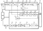
- the first and second transceivers 101 1 and 101 2 include a control unit 102, a transmission unit 103, a transmission / reception radio unit 104, and a reception unit 107.
- the control unit 102 is a computer that includes a CPU, a storage device, and the like, and controls the transmission unit 103, the transmission / reception wireless unit 104, and the reception unit 107 based on software instructions.
- the control unit 102 generates digital (or analog) data to be transmitted (hereinafter referred to as “transmission data”) and data received from other transceivers (hereinafter referred to as “reception data”). It has a function to process according to the application.
- the transmission data and the reception data are image data, audio data, and the like.
- control unit 102 controls the timing of burst (intermittent) transmission by the transmission unit 103 and the transmission / reception radio unit 104 when transmitting the OFDM signal to another transceiver. At the same time, the control unit 102 controls the interference detection function of transmission path characteristics and the estimation function of transmission path distortion of transmission path characteristics by the reception unit 107.
- the transmission unit 103 digitally processes transmission data in accordance with an instruction from the control unit 102 to generate an OFDM signal and supply it to the transmission / reception radio unit 104.
- the transmission / reception radio unit 104 performs up-conversion processing, DA conversion processing, low-pass filter processing, amplification processing, and the like on the OFDM signal supplied from the transmission unit 103 as necessary, and a transmission coupler 105 connected to the power line 108. Wirelessly transmit to.
- the transmission / reception radio unit 104 receives the OFDM signal transmitted from the other transceiver 101 and transmitted wirelessly from the wireless coupler 106, and performs amplification processing, filter processing, AD conversion processing, down-conversion as necessary. Processing is performed and the data is supplied to the reception unit 107.
- the reception unit 107 receives the OFDM signal transmitted from the other transceiver 101 via the transmission / reception wireless unit 104, and generates reception data by performing predetermined processing.
- the receiving unit 107 detects the presence of interference of transmission path characteristics for a predetermined period, and receives the OFDM signal transmitted from the transmission unit 103, thereby transmitting a transmission path of transmission path characteristics. Estimate the strain.
- the transmission / reception wireless unit 104 and the transmission coupler 105 and the reception coupler 106 are not limited to wireless communication but may be wired communication. Further, the transmission coupler 105 and the reception coupler 106 are not necessarily configured separately, and may be configured to separate transmission and reception signals using the same coupler.
- FIG. 2 is a block diagram of the transceiver 101 according to the present embodiment.
- the transmission unit 103 includes a modulation unit 202, a pilot and guard insertion unit 203, a subcarrier allocation unit 204, a pre-equalization processing unit 205, an IFFT unit 206, a CP addition unit 207, a preamble insertion unit 208, and a prediction buffer unit 214.
- the modulation unit 202 modulates the transmission data 201 supplied from the controller 102 for each subcarrier using a modulation scheme such as BPSK, QPSK, PSK-M, QAM, or QAM-M, and performs parallelization.
- Pilot and guard insertion section 203 inserts pilot subcarriers for synchronization processing and equalization processing and guard subcarriers for preventing intersymbol interference in the frequency domain into the symbol sequence obtained by modulation section 202. .
- the subcarrier allocation unit 204 selects or cancels the subcarrier based on the interference avoidance mask supplied from the reception unit 107.
- the pre-equalization processing unit 205 determines the assigned subcarrier based on the current channel distortion predicted by the prediction buffer unit 214 according to the transmission channel distortion of the past transmission channel characteristics estimated by the reception unit 107. Pre-equalize the symbol sequence that has ("pre-equalization process").
- the IFFT unit 206 performs an inverse fast Fourier transform (IFFT) process on the symbol sequences collectively to perform OFDM modulation.
- the CP adding unit 207 adds a cyclic prefix (CP) for assisting synchronization.
- the preamble insertion unit 208 concatenates the short and long preambles for frame, timing, and frequency synchronization to generate an OFDM signal.
- the OFDM signal is supplied to the transmitting / receiving radio device 104 and transmitted to the other transceiver 101 via the power line 108. Note that these functions of the transmission unit 103 are performed under the control of the control unit 102.
- the OFDM signal is composed of OFDM frames concatenated with preambles.
- One OFDM frame is a series of N OFDM symbols composed of 640 subcarriers.
- the pilot carrier has four different values [1, j, ⁇ 1, ⁇ j], and one pilot subcarrier is inserted for each of the 12 modulated data symbols while changing the value.
- 640 subcarriers are added with 400 data subcarriers, 65 guard subcarriers and 47 pilot subcarriers, and 128 cyclic prefixes that are repetitions of the last 128 samples. It is a thing.
- the short and long preambles follow the IEEE 802.11 standard. The present invention is not limited to this example.
- the reception unit 107 includes a light synchronization unit 209, a CP removal unit 210, an FFT unit 211, a first transmission path distortion estimation unit 212, an interference estimation unit 213, a subcarrier estimation unit 215, an all semi-blind synchronization unit 216, a second Transmission path distortion estimation unit 217, equalization processing unit 218, and demodulation unit 219.
- the light synchronization unit 209 receives the OFDM signal transmitted from the transmission unit 103 of its own transceiver 101 and easily synchronizes with the OFDM signal.
- CP removing section 210 removes a cyclic prefix (CP) from the synchronized OFDM signal.
- the FFT unit 211 decomposes the CP-removed signal into subcarriers by fast Fourier transform (FFT).
- the first transmission path distortion estimation unit 212 estimates transmission path characteristics (transmission path transfer function) based on the obtained subcarriers and the known symbols supplied from the transmission unit 103, and estimates the transmission.
- the path distortion is supplied to the prediction buffer 214 of the transmission unit 103.
- the interference estimation unit 213 detects the presence of interference (impulsive noise) in the transmission path characteristic via the transmission / reception radio unit 104 and supplies an interference avoidance mask to the transmission unit 103.
- the subcarrier estimation unit 215 receives an OFDM signal transmitted from another transceiver, and estimates a subcarrier allocated in the received OFDM signal by a semi-blind estimation method. All semi-blind synchronization sections 216 synchronize the received OFDM signal based on the preamble in the received OFDM signal.
- the second transmission path distortion estimation unit 217 estimates transmission path distortion of transmission path characteristics for the received OFDM signal.
- the equalization processing unit 218 equalizes the received OFDM signal based on the estimated transmission path distortion.
- the demodulation unit 219 generates reception data 220 by demodulating the equalized signal and supplies it to the control unit 102.
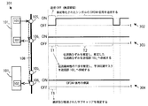
- the first transceiver 101 1 is in transmit mode, an operational timing diagram in the case of transmitting the OFDM signal to the second transceiver 101 2 in the receive mode.
- OFDM signals are transmitted from the first transceiver 101 1, OFDM signal in the second transceiver 101 2 is received.
- a first transceiver 101 1 "transmission side" transceiver 101, a second transceiver 101 2 "of the receiving side” are transceiver 101.
- the first transmission portion 103 1 of the transceiver 101 1, and transmits the OFDM signal to the second transceiver 101 2 via the transmission coupler 105 1 connected to the power line 108.
- the transmitted OFDM signal, the receiving unit 107 2 of the first transceiver 101 first receiving section 107 1 and a second transceiver 101 2 receives via the respective receiver couplers 106 1 and receiver coupler 106 2 Yes.
- Timing charts 302-304 are respectively, a first transmission portion 103 1 and the receiving portion 107 1 of the transceiver 101 1, and the second operation timing of the receiving portion 107 second transceiver 101 2.
- the horizontal axis in FIG. 3 is the time axis t.
- the transmission of the OFDM signal from the transmission unit 103 1 of the first transceiver 101 1 is performed in bursts (intermittently).
- the first transceiver 101 1 in the transmission mode for a predetermined period T1 (hereinafter, referred to as "silent period T1".) Oite, does not transmit the OFDM signals from the transmitting unit 103 1 to the second transceiver 101 2 .
- the silence period T1 may be three OFDM symbol periods.
- the reception unit 107 1 of the first transceiver 101 1 monitors the transmission line via the reception coupler 106 1 during the silent period T1, and detects the presence of interference in the transmission line characteristic. Then, the reception unit 107 1 of the first transceiver 101 1 generates an interference avoidance mask based on the information of the detected interference, and supplies it first to the transmission unit 103 1 of the transceiver 101 1.
- the interference avoidance mask is used by the transmission unit 103 1 of the first transceiver 101 1 to select and cancel a subcarrier to be transmitted.
- the receiving unit 107 2 of the second transceiver 101 2 in the receiving mode is in the silent period T1 during which the receiving unit 107 1 of the first transceiver 101 1 detects the presence of interference of the transmission path characteristics. via the receiving coupler 106 1 monitors the transmission line, detecting the presence of interference of the transmission path characteristics.
- the second transceiver 101 2 it can be estimated interference avoidance mask used by the first transceiver 101 1, as a result, the first transceiver 101 1 which is the transmission side, what subcarriers It can be estimated whether it has been selected and canceled.
- the transmission unit 103 1 of the first transceiver 101 1 performs subcarrier selection and cancellation processing using an interference avoidance mask during a predetermined period T2 (hereinafter referred to as “transmission period T2”) following the silence period T1, and the OFDM signal pre-equalization processing has been performed using a strain transmission path predicted channel characteristics, and transmits the second to the transceiver 101 2.
- Receiver 107 1 of the first transceiver 101 1 in the transmission period T2 for receiving an OFDM signal transmitted from the transmitting unit 103 1 of the first transceiver 101 1 to the second transceiver 101 2.
- Receiver 107 1 of the first transceiver 101 1 in the transmission period T2 based on the received OFDM signal, estimates transmission line characteristics, estimates the first transceiver 101 1 of the transmitter 103 first prediction buffer 214 Supply the transmission line characteristics.
- Receiver 107 of the second transceiver 101 in the transmission period T2, receives the OFDM signal transmitted from the first transceiver 101 1 demodulates, and generates the received data.
- the reception unit 107 of the transceiver 101 monitors the transmission path and detects interference in the transmission path characteristics.
- interference impulse noise
- the receiving unit 107 of the transceiver 101 detects a frequency element having a predetermined power.
- FIG. 4 is a block diagram of an interference estimation unit 213 that generates an interference avoidance mask used for subcarrier selection and cancellation.
- the interference estimation unit 213 includes a complex baseband signal acquisition unit 401, a periodogram calculation unit 402, a noise floor estimation unit 403, a threshold setting unit 404, and an interference avoidance mask generation unit 405.
- the complex baseband signal acquisition unit 401 monitors the state in the transmission path via the reception coupler 106 and acquires the complex baseband signal of the transmission path.
- the periodogram calculation unit 402 calculates a periodogram on the acquired complex baseband signal.
- the noise floor estimation unit 403 estimates the noise floor from the result obtained by the periodogram calculation.
- the threshold setting unit 404 sets a threshold according to the application.
- the interference avoidance mask generation unit 405 generates an interference avoidance mask having the same length as the number of subcarriers and supplies it to the transmission unit 103.
- the periodogram is a power spectral density estimate.
- the periodogram is expressed by Equation 1: Calculated from Here, S (e j ⁇ ) is a power spectral density estimate, ⁇ is a frequency, N is a positive integer, ⁇ is a complex baseband signal, and w is a used window function (for example, Hanning window).
- the calculation of the periodogram is performed using a fast Fourier transform (FFT).
- FFT fast Fourier transform
- the noise floor is necessary to set an appropriate threshold used to detect the presence of interference.
- the noise floor is calculated by (1) N power spectral densities (PSD) obtained by periodogram calculation in descending order, and (2) N power spectral densities (in descending order) ( It can be obtained by calculating the average of the sum of the power spectral density of one quarter from the back of the PSD).
- the N power spectral densities (PSDs) are arranged in descending order in order to put a relatively high PSD at the beginning of the PSD vector and a relatively low PSD at the back.
- Equation 2 Is estimated from
- NF is the noise floor
- N is the number of power spectral densities
- sortedPSDi is the power spectral density arranged in descending order.
- the threshold setting unit 404 sets the threshold according to the application.
- the threshold value may be a fixed value that is determined in advance by the user and stored in the transceiver 101 in advance.
- the threshold may be set to 10 dB from the estimated noise floor, or may be set to the estimated noise floor value.
- a frequency having a power spectral density larger than the set threshold can be estimated as interference.
- the interference avoidance mask has the same length as the number of subcarriers excluding the cyclic prefix (for example, 512 in the above example) in the interference avoidance mask generation unit 405, and is “0” for frequencies where interference exists. Values are generated to have a value of “1” for other frequencies.
- the number of values of “1” and the frequency having a value of “1” in the interference avoidance mask are equal to the number and frequency of all subcarriers excluding the transmitted cyclic prefix.
- FIG. 5A shows, as an example, an actual graph of the complex baseband spectrum 501 including the interference 504 of the transmission path characteristics detected by the interference estimation unit 213, a schematic diagram of the interference avoidance mask 502 generated therefrom, It is an actual graph of the subcarrier spectrum 503 allocated based on the interference avoidance mask by the carrier allocation unit 204.
- the interference avoidance mask 502 has a value of “0” for the frequency where the interference 504 of the transmission path characteristic exists, and has a value of “1” for other frequencies.
- the interference avoidance mask 502 is supplied to the transmitter 103 and simply multiplied with the modulated subcarrier 506 as shown in FIG. 5B. Thereby, subcarrier selection and cancellation are performed, and a subcarrier 505 that avoids interference 504 is assigned to an OFDM signal transmitted to another transceiver 101.
- the generated interference avoidance mask is also used for estimating transmission path distortion of transmission path characteristics.
- the transceiver 101 can adapt to changes in the transmission path characteristics of the transmission path in real time, and can transmit an OFDM signal having almost no interference (impulse noise) in the transmission path characteristics. To do.
- the second transceiver 101 2 that receives the OFDM signal from the first transceiver 101 1 receives the interference estimation unit 213 of the receiving unit 107 2 of the second transceiver 101 2 during the silence period T1. in 2, it is possible to produce the same interference avoidance mask and the first interference avoidance mask generated by transceiver 101 1.
- the number of values of “1” and the frequency having a value of “1” in the interference avoidance mask are equal to the number of all subcarriers transmitted and the corresponding frequency. Therefore, the subcarrier estimation unit 215 2 of the reception unit 107 2 of the second transceiver 101 2 that receives the OFDM signal estimates which subcarrier is selected and which subcarrier is canceled in the received OFDM signal. can do.
- the interference estimation unit 213 generates the interference avoidance mask not only in the silent period T1, but in any period. That is, during the transmission period T2, the interference estimation unit 213 detects interference in the transmission path, generates an interference avoidance mask, stores the interference avoidance mask, and generates it when the next OFDM signal is generated. It may be used.
- the receiving transceiver 101 when the receiving transceiver 101 is in the receiving mode, in order to understand which subcarriers have been selected and canceled, it always monitors the transmission path, detects the presence of interference, and avoids interference every moment. Generate masks and store them. Then, using the interference avoidance mask when the OFDM signal is transmitted (or the immediate vicinity thereof), the receiving-side transceiver 101 selects which subcarrier in the received OFDM signal and which subcarrier is canceled. You can know what was done.
- the transmission unit 103 1 of the first transceiver 101 1 in the transmission mode transmits the OFDM signal to the second transceiver 101 2 in the transmission period T2.
- the receiving unit 107 1 of the first transceiver 101 1 receives the transmitted OFDM signal by itself and uses it to estimate the transmission path distortion of the transmission path characteristics.
- the transmission unit 103 1 of the first transceiver 101 1 performs an equalization process (pre-equalization process) in advance on the symbol to be transmitted next using the estimated transmission path distortion.
- the receiving unit 107 of the transceiver 101 receives information on the transmitted OFDM symbol (hereinafter referred to as “known symbol”) from the transmitting unit 103. Since the receiving unit 107 of the transceiver 101 knows a known symbol, it can estimate the transmission path distortion of the transmission path characteristics. As a result, pre-equalization processing is realized.
- the pre-equalization processing performed on the symbol to be transmitted in advance by the transmission-side transceiver 101 is more effective than the case where the reception-side transceiver 101 performs equalization processing on the reception-side transceiver 101 alone. There is an advantage of increasing the noise ratio).
- the principle of the pre-equalization process according to this embodiment is shown below.
- Equation 3 the signal R n received by the transceiver 101 at a certain time is given by Equation 3: It is represented by Here, S n is an unknown transmitted symbol, H n is transmission path distortion, and N n is noise added to the signal through the transmission path.
- the pre-equalization processing is to transmit the symbol to be transmitted in advance by ideally multiplying the symbol to be transmitted in advance by the reciprocal of the transmission path distortion. Then, the reception signal subjected to the pre-equalization process is expressed by Equation 4: It is represented by
- G n is the reciprocal of the predicted transmission line distortion, It is. If the predicted transmission line distortion is accurate, G n is a pre-equalization factor that is the inverse H ⁇ 1 of the true transmission line distortion. Further, a n is the amplitude coefficient, the phi n is the phase coefficient.
- the OFDM signal transmitted from the transmission unit 103 of the transceiver 101 is received by its own reception unit 107.
- the received OFDM signal is a signal generated and transmitted by itself, the interference avoidance mask used for subcarrier selection and cancellation is known, and the voltage controlled oscillator that drives the radio board is the same, Since there is no need for carrier frequency recovery and tracking, timing, and the time at which symbols are transmitted, the light synchronization unit 209 of the reception unit 107 can easily synchronize the received OFDM signal.
- phase compensation needs to be considered.
- the phase offset ⁇ d is linearly related to frequency and is expressed in Equation 6: It is represented by
- ⁇ d is a fixed phase offset, and is estimated by taking a phase difference between a known symbol and a received symbol distorted due to the influence of transmission path characteristics.
- the fixed phase offset ⁇ d calculates the average of this phase difference for all symbols. In this manner, the light synchronization unit 209 performs phase compensation and achieves synchronization.
- the first transmission path distortion estimation unit 212 simply estimates the transmission path distortion of the transmission path characteristics by performing zero forcing equalization using a known symbol. be able to.
- the estimated transmission line distortion is supplied to the prediction buffer 214 and stored therein.
- the transmission path distortion estimated by receiving the OFDM symbol (OFDM signal) transmitted at a certain time t1 cannot be used for the pre-equalization process at the time t1, but the subsequent time t2 (> t1) Can be used for pre-equalization processing when transmitting OFDM symbols.
- the channel distortion of the channel characteristics estimated in the past may be used as it is, but the channel distortion may change between consecutive OFDM symbols (OFDM signals). It is desirable to predict current transmission line distortion using transmission line distortion.
- the prediction buffer 214 of the transmission unit 103 stores the transmission path characteristics estimated by the first transmission path distortion estimation unit 212 at the past times t 0-2 and t 0-1 (t 0-2 ⁇ t 0-1 ). Is stored, and the current transmission line distortion at t 0 is predicted.
- the prediction buffer 214 includes a circular buffer and the like.
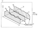
- FIG. 6 shows the channel distortion H (f) of the estimated channel characteristics at the past times t 0-2 and t 0-1 (t 0-2 ⁇ t 0-1 ) stored in the prediction buffer 214.
- the symbol “ ⁇ ” is a hat symbol and indicates an estimation.
- the axis extending in the upper right direction toward the drawing is the time axis t
- the axis extending in the lower right direction toward the drawing is the frequency axis f
- the axis extending upward in the drawing is estimated.
- of the predicted transmission line distortion is the absolute value
- the transmission path distortion prediction unit 601 of the prediction buffer 214 may be an OFDM symbol (or an OFDM signal or an OFDM burst received at past times t 0-2 and t 0-1 . It can be changed as appropriate according to the application. ) Estimated transmission line distortion H (f) ⁇
- the transmission path distortion prediction unit 601 may use any prediction architecture.
- Equation 7 Can be used.
- the weighting function ⁇ (f) is a constant vector different for each frequency bottle.
- the reciprocal of the transmission path distortion predicted by the transmission path distortion prediction section 601 that is, the reverse transmission path distortion ⁇ H (f) ⁇
- t 0-1 ⁇ ⁇ 1 G n is pre-equalized by the transmission section 103. It is supplied to the processing unit 205 and used for pre-equalization processing.
- FIG. 7 is a flowchart illustrating a method for transmitting an OFDM signal from the first transceiver 1011 to the second transceiver 101 2 via the power line 108.
- the transmission unit 103 1 of the first transceiver 101 1 in the transmission mode is to generate an OFDM signal to be transmitted to the transceiver 101 2, it modulates the transmit data 201 (step 701).
- the transmitter 103 1 of the first transceiver 101 1 inserts the pilot subcarrier and the guard subcarrier into the modulated symbol and supplies the symbol to the receiver 107 1 of the first transceiver 101 1 (step 702). .
- the transmission path is monitored to estimate the interference of the transmission path characteristics (step 703).
- the first receiving section 107 first transceiver 101 1, based on the interference of the transmission path is estimated to generate an interference avoidance mask, and supplies the first to the transmitter 103 first transceiver 101 1 (step 704).
- the transmission unit 103 1 of the first transceiver 101 1 uses the interference avoidance mask in the subcarrier allocation unit 204 to select and cancel the subcarrier (step 705).
- the first transmission portion 103 1 of the transceiver 101 1 predicts the distortion current transmission path by using a strain transmission path of the transmission path characteristic estimated in the past by the receiving portion 107 1 of the first transceiver 101 1 (step 706).
- the transmission unit 103 1 of the first transceiver 101 1 performs pre-equalization processing on the symbols based on the predicted transmission path distortion (step 707).
- the transmission unit 103 1 of the first transceiver 101 1 performs IFFT processing, cyclic prefix (CP) addition processing, and preamble concatenation processing on the pre-equalized symbols to generate an OFDM signal (step 708).
- the first receiving section 107 first transceiver 101 1 receives the OFDM signal transmitted from the transmitting unit 103 1 of the first transceiver 101 1, the transmission unit 103 1 of the OFDM signal received with the first transceiver 101 1
- the transmission path distortion of the transmission path characteristics is estimated based on the known symbols supplied from (step 710).
- the first receiving section 107 first transceiver 101 1 and supplies the distortion transmission path is the estimated for use in the next transmission, to the first transceiver 101 1 of the transmitter 103 first prediction buffer 214 ( Step 711).
- the flow is repeated from step 701.
- the transmission mode of the first transceiver 101 1 is finished (Yes in Step 712)
- the transmission of the OFDM signal from the first transceiver 1011 to the second transceiver 101 2 is finished (Step 713).
- the transmission unit 103 of the transceiver 101 is turned off and receives the OFDM signal transmitted from the other transceiver 101 via the power line 108.
- OFDM frame synchronization, clock recovery, carrier recovery, phase, and timing synchronization are performed.
- the receiving-side transceiver 101 can estimate which subcarrier is allocated while transmission is interrupted. As described above, while transmission is interrupted, the subcarrier estimation unit 215 of the receiving-side transceiver 101 detects the presence of interference in the transmission path characteristics, and generates an interference avoidance mask based on the same principle as described above. Thereby, the transceiver 101 on the receiving side can estimate which subcarrier is allocated in the received OFDM signal.
- all semi-blind synchronization units 216 of the transceiver 101 on the receiving side perform synchronization processing on the received OFDM signals.
- the OFDM frame synchronization is performed simply by correlating the received data with the short preamble. After the correlation process, the maximum peak is detected. The detected maximum peak indicates the beginning of the OFDM frame.
- FIG. 8 is a block diagram illustrating an example for clock, timing, and frequency synchronization.
- the Faro non-integer delay unit 801 synchronizes the timing, and as will be understood by those skilled in the art, the derotation unit 802, the cyclic prefix compensation frame offset unit 803, the received OFDM signal processing unit 804, the numerically controlled oscillator Synchronization processing is performed using 805, the timing control unit 806, and the like.
- the receiving transceiver 101 can decode the received symbol.
- the power line 108 is greatly affected by interference, fading, noise, and the like, even if pre-equalization processing is performed in the transceiver 101 on the transmission side, a part of the transmission path distortion of the transmission path characteristics is estimated. There is a possibility that the transmitted OFDM signal is distorted. Therefore, it is preferable that the receiver-side transceiver 101 further performs simple equalization processing.
- the second transmission path distortion estimation unit 217 and the equalization processing unit 218 of the receiving-side transceiver 101 use the long preamble of the received OFDM signal for equalization processing.
- the equalization processing in the second transmission path distortion estimation unit 217 estimates transmission path distortion using a known preamble.
- FIG. 9 is a block diagram of the second transmission path distortion estimation unit 217 of the reception unit 107 of the transceiver 101 on the reception side.
- the second transmission line distortion estimation unit 217 includes a sequential least squares (RLS) algorithm processing unit 901 and a least mean square (LMS) algorithm processing unit 902.
- RLS sequential least squares
- LMS least mean square
- the input signal is sequentially subjected to least square (RLS) algorithm processing 901 using a known long preamble to estimate the transmission path distortion of the transmission path characteristics.
- LMS least-squares mean
- the RLS algorithm processing 901 enables high-speed convergence, but has high complexity. Therefore, once it converges, it changes to the LMS algorithm process 902 which has low complexity.
- the transmission path distortion estimated by the RLS algorithm processing unit 901 is supplied to the LMS algorithm processing unit 902 as an input.
- This double algorithm processing configuration has the advantage that complexity can be reduced while enabling fast convergence. Also, with this double algorithm processing configuration, the bit error rate (BER) can finally be reduced on the order of 10 times that of normal equalization processing.
- BER bit error rate
- Equation 8 Is used to estimate the transmission path distortion.
- the transmission line distortion is continuously estimated using.
- the equalization processing unit 218 of the transceiver 101 on the receiving side performs equalization processing.
- the receiving-side transceiver 101 is not limited to the one that performs the above-described synchronization processing and equalization processing. Unlike a normal transceiver, the receiving-side transceiver 101 needs to further include a subcarrier estimation unit 215, but conventional synchronization processing and equalization processing may be used.
- the demodulating unit 219 of the transceiver 101 on the transmitting side demodulates the equalized symbols, generates reception data, and supplies the received data to the control unit 102.
- Figure 10 is a flowchart illustrating a method of receiving an OFDM signal by the second transceiver 101 2.
- the transmission unit 103 1 of the first transceiver 101 1 transmits the OFDM signal.
- Receiver 107 of the second transceiver 101 based on the interference estimated channel characteristics, to generate an interference avoidance mask (step 1002).
- the receiving unit 107 2 of the second transceiver 101 2 estimates the assigned subcarrier of the OFDM signal transmitted from the first transceiver 101 1 using the interference avoidance mask (step 1003). .
- Receiver 107 of the second transceiver 101 frame synchronization of the received OFDM signal, timing synchronization, clock synchronization, performing frequency synchronization processing (step 1004).
- Receiver 107 of the second transceiver 101 2 estimates a distortion transmission path channel characteristics (step 1005).
- Receiver 107 of the second transceiver 101 2 using the transmission path distortion is estimated, perform the equalization processing (step 1006).
- Receiver 107 of the second transceiver 101 2 demodulates the symbol equalization processing has been performed, to generate the received data (step 1007).
- Receiver 107 of the second transceiver 101 2 supplies it second transceiver 101 2 to the control unit 102 2 (step 1008).
- step 1010 In a case where the reception mode of the second transceiver 101 2 is not completed (No in step 1009), the flow is repeated from step 1001. If the reception mode of the second transceiver 101 2 ends (Yes in step 1009), receiving the first transmitted OFDM signals from the transceiver 101 1 to the second transceiver 101 2 is terminated (step 1010) .
- the transceiver according to an embodiment of the present invention may realize the functions described so far by either hardware or software.
- one embodiment of the present invention is applicable to short-distance communication via any power line.
- the present invention can be applied to power line communication at home or in a car.
- various devices are connected to the power line in the automobile, and communication via the power line in the automobile is easily affected by interference, fading, noise, and the like.
- the transceiver according to an embodiment of the present invention can reduce such influence and can be suitably used for power line communication in an automobile.
- a power line communication transceiver and a power line communication method include a pre-equalization function and an interference avoidance function, and noise (interference) and distortion caused by a power line as a transmission path. Even under the influence of this, reliable communication is possible at a high bit rate.
- 100 cognitive short-range power line communication system
- 101 transceiver
- 102 control unit
- 103 transmission unit
- 104 transmission / reception radio unit
- 105 transmission coupling unit
- 106 reception coupling unit
- 107 reception unit
- 108 power line
- 109 Other device
Landscapes
- Engineering & Computer Science (AREA)
- Signal Processing (AREA)
- Computer Networks & Wireless Communication (AREA)
- Power Engineering (AREA)
- Cable Transmission Systems, Equalization Of Radio And Reduction Of Echo (AREA)
- Noise Elimination (AREA)
Description
図1は、本発明の一実施形態に係る電力線を介したコグニティブ短距離電力線通信システム100を示す模式図である。
Frequency Division Multiplexing)信号を送信する。そして、第1及び第2のトランシーバ1011及び1012は、それと同時に、伝送路特性の伝送路ひずみによりひずみ、そしてノイズや干渉が加わったその送信された信号を受信する全二重通信を可能にする。一方、受信モードにおいて、第1及び第2のトランシーバ1011及び1012は、相手のトランシーバから送信されたOFDM信号を受信する。さらに、第1及び第2のトランシーバ1011及び1012は、送信モード及び受信モードの両方において、伝送路特性の干渉を検知する。
図4は、サブキャリアの選択及び取消しのために使用される干渉回避マスクを生成する干渉推定部213のブロック図である。


送信モードにある第1のトランシーバ1011の送信部1031は、送信期間T2において、OFDM信号を第2のトランシーバ1012へ送信する。一方、送信期間T2において、第1のトランシーバ1011の受信部1071は、送信されたOFDM信号を自ら受信し、それを伝送路特性の伝送路ひずみを推定するために利用する。そして、第1のトランシーバ1011の送信部1031は、推定した伝送路ひずみを用いて、次に送信するシンボルに対して事前に等化処理(事前等化処理)を施す。





図7は、第1のトランシーバ1011から第2のトランシーバ1012へ電力線108を介してOFDM信号の送信方法を表すフローチャートである。
トランシーバ101は、受信モードにあるとき、トランシーバ101の送信部103がOFF状態になり、他のトランシーバ101から電力線108を介して送られてくるOFDM信号を受信する。送られたOFDM信号から受信データ220を取り出すために、OFDMフレーム同期、クロック回復、キャリア回復、位相、タイミング同期を行う。
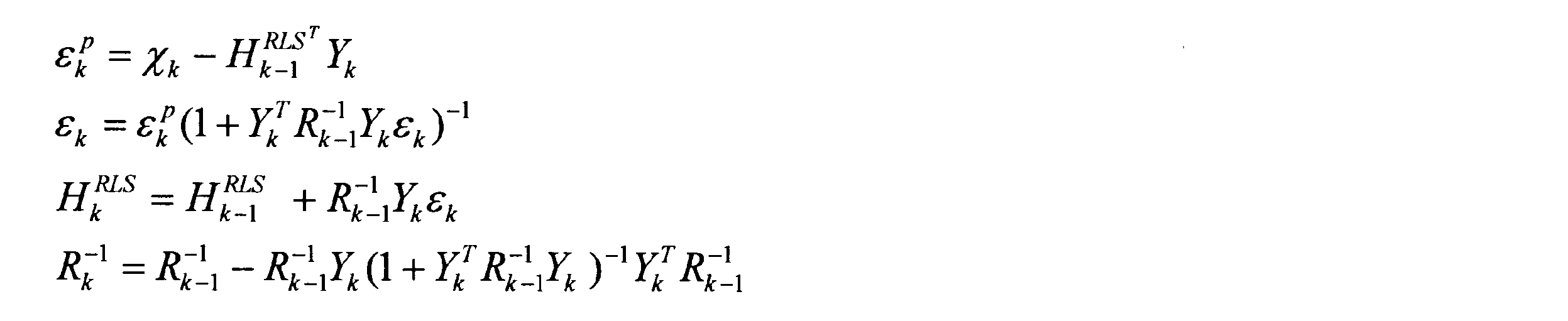

図10は、第2のトランシーバ1012によるOFDM信号の受信方法を表すフローチャートである。
Claims (9)
- 信号を送信する送信部と、
信号を受信し、伝送路特性を推定する受信部を備える電力線通信用トランシーバ。 - 推定した伝送路特性の干渉を基に干渉回避マスクを生成する干渉推定部と、
前記干渉回避マスクを用いて、送信されるべき信号のサブキャリアを選択し又は取り消すサブキャリア割り当て部をさらに備える請求項1に記載の電力線通信用トランシーバ。 - 前記送信部により送信された信号を受信し、前記受信した信号を基に伝送路特性の伝送路ひずみを推定する伝送路ひずみ推定部と、
前記推定された伝送路ひずみを用いて、送信されるべき信号を事前に等化する事前等化処理部をさらに備える、請求項1又は2に記載の電力線通信用トランシーバ。 - 推定した伝送路特性の干渉を基に干渉回避マスクを生成し、前記干渉回避マスクを用いて、受信した信号の割り当てられたサブキャリアを推定するサブキャリア推定部をさらに備える、請求項1乃至3のいずれか1項に記載の電力線通信用トランシーバ。
- 前記伝送路が電力線であり、
前記信号がOFDM信号であり、
前記電力線通信用トランシーバが、同一の中心周波数で同時に送受信を行うことができる全二重通信機能を有する電力線通信用コグニティブトランシーバである、請求項1乃至4のいずれか1項に記載の電力線通信用トランシーバ。 - 自動車内の電力線へ信号を送信する送信部と、
前記電力線から信号を受信し、伝送路特性を推定する受信部と、
推定した伝送路特性の干渉を基に干渉回避マスクを生成する干渉推定部と、
前記干渉回避マスクを用いて、送信されるべき信号のサブキャリアを選択し又は取り消すサブキャリア割り当て部と、
前記送信部により送信された信号を受信し、前記受信した信号を基に伝送路特性の伝送路ひずみを推定する伝送路ひずみ推定部と、
前記推定された伝送路ひずみを用いて、送信されるべき信号を事前に等化する事前等化処理部とを備える、自動車内の電力線通信用トランシーバ。 - 伝送路特性を推定するステップと、
前記推定された伝送路特性の干渉を基に干渉回避マスクを生成するステップと、
前記干渉回避マスクを用いて、送信されるべき信号のサブキャリアを選択し又は取り消すステップと、
前記信号を送信するステップを具備する電力線通信方法。 - 前記送信した信号を受信するステップと、
前記受信した信号を基に伝送路特性の伝送路ひずみを推定するステップと、
前記推定した伝送路ひずみを用いて、送信されるべき信号を事前に等化するステップをさらに具備する請求項7に記載の電力線通信方法。 - 前記推定された伝送路特性の干渉を基に干渉回避マスクを生成するステップと、
前記干渉回避マスクを用いて、受信した信号の割り当てられたサブキャリアを推定するステップを具備する請求項7又は8に記載の電力線通信方法。
Priority Applications (3)
| Application Number | Priority Date | Filing Date | Title |
|---|---|---|---|
| CN201380049009.5A CN104641568A (zh) | 2012-09-20 | 2013-09-18 | 电力线通信用收发器以及电力线通信方法 |
| US14/423,597 US20150229358A1 (en) | 2012-09-20 | 2013-09-18 | Power line communication transceiver and power line communication method |
| DE112013004588.5T DE112013004588T5 (de) | 2012-09-20 | 2013-09-18 | Stromleitungskommunikations-Sender-Empfänger und Stromleitungskommunikationsverfahren |
Applications Claiming Priority (2)
| Application Number | Priority Date | Filing Date | Title |
|---|---|---|---|
| JP2012-206932 | 2012-09-20 | ||
| JP2012206932A JP2014064100A (ja) | 2012-09-20 | 2012-09-20 | 電力線通信用トランシーバ及び電力線通信方法 |
Publications (1)
| Publication Number | Publication Date |
|---|---|
| WO2014045566A1 true WO2014045566A1 (ja) | 2014-03-27 |
Family
ID=50340905
Family Applications (1)
| Application Number | Title | Priority Date | Filing Date |
|---|---|---|---|
| PCT/JP2013/005502 Ceased WO2014045566A1 (ja) | 2012-09-20 | 2013-09-18 | 電力線通信用トランシーバ及び電力線通信方法 |
Country Status (5)
| Country | Link |
|---|---|
| US (1) | US20150229358A1 (ja) |
| JP (1) | JP2014064100A (ja) |
| CN (1) | CN104641568A (ja) |
| DE (1) | DE112013004588T5 (ja) |
| WO (1) | WO2014045566A1 (ja) |
Cited By (2)
| Publication number | Priority date | Publication date | Assignee | Title |
|---|---|---|---|---|
| CN111030730A (zh) * | 2019-12-05 | 2020-04-17 | 国网天津市电力公司电力科学研究院 | 一种低压电力线噪声录制及注入系统 |
| CN112821922A (zh) * | 2021-02-23 | 2021-05-18 | 青岛鼎信通讯股份有限公司 | 一种基于中压载波的机架式载波通讯管理机 |
Families Citing this family (8)
| Publication number | Priority date | Publication date | Assignee | Title |
|---|---|---|---|---|
| EP2852069A1 (en) * | 2013-09-24 | 2015-03-25 | ABB Research Ltd. | System for transmitting and receiving a power line communication signal over the power bus of a power electronic converter |
| JP6384792B2 (ja) * | 2015-01-09 | 2018-09-05 | パナソニックIpマネジメント株式会社 | 通信システム |
| CN104954112B (zh) * | 2015-06-29 | 2018-05-29 | 国网智能电网研究院 | 一种基于细频率颗粒度的跨频带电力线载波频率认知方法 |
| CN106211182B (zh) * | 2016-07-13 | 2019-03-26 | 山东农业大学 | 一种基于统计信道信息的认知全双工功率分配方法 |
| JP6689158B2 (ja) * | 2016-08-04 | 2020-04-28 | 日立オートモティブシステムズ株式会社 | 電力線通信機能を備えた電子制御システムおよびそれを用いた自動車 |
| EP3293845A1 (en) * | 2016-09-08 | 2018-03-14 | Alcatel Lucent | Circuit breaker for power line communication |
| US11140008B2 (en) | 2017-12-07 | 2021-10-05 | Halliburton Energy Services, Inc. | Noise compensation for communication on power line downhole |
| CN107872248B (zh) * | 2017-12-27 | 2021-04-20 | 北京三清互联科技有限公司 | 一种电力线宽带载波通信方法 |
Citations (7)
| Publication number | Priority date | Publication date | Assignee | Title |
|---|---|---|---|---|
| JPH11215095A (ja) * | 1998-01-28 | 1999-08-06 | Jisedai Digital Television Hoso System Kenkyusho:Kk | Ofdm信号送出装置 |
| JP2000216752A (ja) * | 1998-11-20 | 2000-08-04 | Mitsubishi Electric Corp | マルチキャリア通信装置 |
| JP2002246963A (ja) * | 2001-02-16 | 2002-08-30 | Sumitomo Electric Ind Ltd | 電力線搬送における多重通信システム |
| JP2002280935A (ja) * | 2001-03-19 | 2002-09-27 | Sumitomo Electric Ind Ltd | 電力線搬送におけるマルチキャリア通信装置及び通信方法 |
| JP2004215038A (ja) * | 2003-01-06 | 2004-07-29 | Sumitomo Electric Ind Ltd | 車両内通信システム、車両内通信方法及び周波数設定装置 |
| JP2005057644A (ja) * | 2003-08-07 | 2005-03-03 | Matsushita Electric Ind Co Ltd | 通信装置 |
| JP2011091791A (ja) * | 2009-09-24 | 2011-05-06 | Toyota Central R&D Labs Inc | 移動体用電力線通信方法 |
Family Cites Families (7)
| Publication number | Priority date | Publication date | Assignee | Title |
|---|---|---|---|---|
| ES2184587B1 (es) * | 2000-12-18 | 2004-08-01 | Diseño De Sistemas En Silicio, S.A. | Sistema y procedimiento de transmision digital de datos punto a multipunto sobre red electrica. |
| JP2007020113A (ja) * | 2005-07-11 | 2007-01-25 | Sumitomo Electric Ind Ltd | 電力線通信装置 |
| CN100377515C (zh) * | 2005-07-14 | 2008-03-26 | 北京邮电大学 | 用于mimo-ofdm系统的自适应传输方法 |
| US8229008B2 (en) * | 2005-07-26 | 2012-07-24 | Nvidia Corporation | Interference mitigation for orthogonal frequency division multiplexing communication |
| JP4349436B2 (ja) * | 2007-06-04 | 2009-10-21 | 株式会社デンソー | 車両用通信装置及び制御情報生成装置 |
| JP5542702B2 (ja) * | 2011-01-12 | 2014-07-09 | 株式会社東芝 | 無線通信装置 |
| US20130029595A1 (en) * | 2011-07-29 | 2013-01-31 | Qualcomm Incorporated | Communications related to electric vehicle wired and wireless charging |
-
2012
- 2012-09-20 JP JP2012206932A patent/JP2014064100A/ja active Pending
-
2013
- 2013-09-18 DE DE112013004588.5T patent/DE112013004588T5/de not_active Withdrawn
- 2013-09-18 WO PCT/JP2013/005502 patent/WO2014045566A1/ja not_active Ceased
- 2013-09-18 US US14/423,597 patent/US20150229358A1/en not_active Abandoned
- 2013-09-18 CN CN201380049009.5A patent/CN104641568A/zh active Pending
Patent Citations (7)
| Publication number | Priority date | Publication date | Assignee | Title |
|---|---|---|---|---|
| JPH11215095A (ja) * | 1998-01-28 | 1999-08-06 | Jisedai Digital Television Hoso System Kenkyusho:Kk | Ofdm信号送出装置 |
| JP2000216752A (ja) * | 1998-11-20 | 2000-08-04 | Mitsubishi Electric Corp | マルチキャリア通信装置 |
| JP2002246963A (ja) * | 2001-02-16 | 2002-08-30 | Sumitomo Electric Ind Ltd | 電力線搬送における多重通信システム |
| JP2002280935A (ja) * | 2001-03-19 | 2002-09-27 | Sumitomo Electric Ind Ltd | 電力線搬送におけるマルチキャリア通信装置及び通信方法 |
| JP2004215038A (ja) * | 2003-01-06 | 2004-07-29 | Sumitomo Electric Ind Ltd | 車両内通信システム、車両内通信方法及び周波数設定装置 |
| JP2005057644A (ja) * | 2003-08-07 | 2005-03-03 | Matsushita Electric Ind Co Ltd | 通信装置 |
| JP2011091791A (ja) * | 2009-09-24 | 2011-05-06 | Toyota Central R&D Labs Inc | 移動体用電力線通信方法 |
Cited By (2)
| Publication number | Priority date | Publication date | Assignee | Title |
|---|---|---|---|---|
| CN111030730A (zh) * | 2019-12-05 | 2020-04-17 | 国网天津市电力公司电力科学研究院 | 一种低压电力线噪声录制及注入系统 |
| CN112821922A (zh) * | 2021-02-23 | 2021-05-18 | 青岛鼎信通讯股份有限公司 | 一种基于中压载波的机架式载波通讯管理机 |
Also Published As
| Publication number | Publication date |
|---|---|
| US20150229358A1 (en) | 2015-08-13 |
| JP2014064100A (ja) | 2014-04-10 |
| CN104641568A (zh) | 2015-05-20 |
| DE112013004588T5 (de) | 2015-06-11 |
Similar Documents
| Publication | Publication Date | Title |
|---|---|---|
| JP2014064100A (ja) | 電力線通信用トランシーバ及び電力線通信方法 | |
| US7826541B2 (en) | Wireless relay system, wireless relay apparatus, and wireless relay method | |
| US7949040B2 (en) | Reception quality measuring apparatus and reception quality measuring method | |
| JP4701964B2 (ja) | マルチユーザ受信装置 | |
| KR100873173B1 (ko) | 셀룰러 직교 주파수 분할 다중화 시스템에서의 동일 채널간섭 제거 시스템 및 방법 | |
| CN101536444A (zh) | 加扰的多载波传输 | |
| KR101241824B1 (ko) | Ofdm 통신 시스템의 수신 장치 및 그의 위상 잡음 완화 방법 | |
| KR20090057862A (ko) | 무선 통신 시스템에서의 채널 추정 방법 및 장치 | |
| US20040151254A1 (en) | Adaptive inter-carrier interference self-cancellation method and transceiver thereof | |
| KR20150064595A (ko) | 가변 가능한 보호 구간을 이용한 데이터 송수신 방법 및 그 장치 | |
| KR20170050100A (ko) | 통신 시스템에서 데이터를 송수신하는 장치 및 방법 | |
| US20110299612A1 (en) | Uncontrolled spatial multiple access in wireless networks | |
| JP2005192109A (ja) | Ofdm無線通信システムのための伝搬路推定器及びこれを用いた受信装置 | |
| EP2499797B1 (en) | Channel estimation in a multi-user mimo-ofdm system in the presence of user terminal symbol-specific phase offsets | |
| JP4809373B2 (ja) | 通信制御方法、受信局装置、送信局装置および通信システム | |
| US8165238B2 (en) | Bi-directional communication system, communication apparatus, and control method of communication apparatus | |
| JP2010124368A (ja) | ドップラー周波数推定装置、受信装置、プログラム、及びドップラー周波数推定方法 | |
| JP2006246129A (ja) | 伝送システム、送信装置及び受信装置 | |
| JP2010119070A (ja) | 位相雑音補償受信機 | |
| JP4551055B2 (ja) | ブロックコード伝送に用いられる受信器及びその受信方法 | |
| JP6969446B2 (ja) | 無線通信システム、無線通信方法および送信装置 | |
| JP2006050631A (ja) | 伝送性能を向上させるためのシステム、モデム、受信器、送信器及びその方法 | |
| JP4675790B2 (ja) | 通信装置および通信システム | |
| KR101441597B1 (ko) | 고속 퓨리에 변환기 기반 주파수 분할 다중 접속시스템에서 주파수 오차 추정 장치 및 방법 | |
| JP2022139409A (ja) | 無線通信システム及び無線通信方法 |
Legal Events
| Date | Code | Title | Description |
|---|---|---|---|
| 121 | Ep: the epo has been informed by wipo that ep was designated in this application |
Ref document number: 13840103 Country of ref document: EP Kind code of ref document: A1 |
|
| WWE | Wipo information: entry into national phase |
Ref document number: 14423597 Country of ref document: US |
|
| WWE | Wipo information: entry into national phase |
Ref document number: 112013004588 Country of ref document: DE Ref document number: 1120130045885 Country of ref document: DE |
|
| 122 | Ep: pct application non-entry in european phase |
Ref document number: 13840103 Country of ref document: EP Kind code of ref document: A1 |