WO2014045346A1 - 成分測定装置 - Google Patents
成分測定装置 Download PDFInfo
- Publication number
- WO2014045346A1 WO2014045346A1 PCT/JP2012/073890 JP2012073890W WO2014045346A1 WO 2014045346 A1 WO2014045346 A1 WO 2014045346A1 JP 2012073890 W JP2012073890 W JP 2012073890W WO 2014045346 A1 WO2014045346 A1 WO 2014045346A1
- Authority
- WO
- WIPO (PCT)
- Prior art keywords
- light
- measurement
- light emitting
- chip
- emitting element
- Prior art date
- Legal status (The legal status is an assumption and is not a legal conclusion. Google has not performed a legal analysis and makes no representation as to the accuracy of the status listed.)
- Ceased
Links
Images




Classifications
-
- A—HUMAN NECESSITIES
- A61—MEDICAL OR VETERINARY SCIENCE; HYGIENE
- A61B—DIAGNOSIS; SURGERY; IDENTIFICATION
- A61B5/00—Measuring for diagnostic purposes; Identification of persons
- A61B5/145—Measuring characteristics of blood in vivo, e.g. gas concentration or pH-value ; Measuring characteristics of body fluids or tissues, e.g. interstitial fluid or cerebral tissue
- A61B5/14532—Measuring characteristics of blood in vivo, e.g. gas concentration or pH-value ; Measuring characteristics of body fluids or tissues, e.g. interstitial fluid or cerebral tissue for measuring glucose, e.g. by tissue impedance measurement
-
- G—PHYSICS
- G01—MEASURING; TESTING
- G01N—INVESTIGATING OR ANALYSING MATERIALS BY DETERMINING THEIR CHEMICAL OR PHYSICAL PROPERTIES
- G01N21/00—Investigating or analysing materials by the use of optical means, i.e. using sub-millimetre waves, infrared, visible or ultraviolet light
- G01N21/84—Systems specially adapted for particular applications
- G01N21/8483—Investigating reagent band
-
- A—HUMAN NECESSITIES
- A61—MEDICAL OR VETERINARY SCIENCE; HYGIENE
- A61B—DIAGNOSIS; SURGERY; IDENTIFICATION
- A61B2562/00—Details of sensors; Constructional details of sensor housings or probes; Accessories for sensors
- A61B2562/02—Details of sensors specially adapted for in-vivo measurements
- A61B2562/0295—Strip shaped analyte sensors for apparatus classified in A61B5/145 or A61B5/157
-
- A—HUMAN NECESSITIES
- A61—MEDICAL OR VETERINARY SCIENCE; HYGIENE
- A61B—DIAGNOSIS; SURGERY; IDENTIFICATION
- A61B5/00—Measuring for diagnostic purposes; Identification of persons
- A61B5/145—Measuring characteristics of blood in vivo, e.g. gas concentration or pH-value ; Measuring characteristics of body fluids or tissues, e.g. interstitial fluid or cerebral tissue
- A61B5/1455—Measuring characteristics of blood in vivo, e.g. gas concentration or pH-value ; Measuring characteristics of body fluids or tissues, e.g. interstitial fluid or cerebral tissue using optical sensors, e.g. spectral photometrical oximeters
-
- G—PHYSICS
- G01—MEASURING; TESTING
- G01N—INVESTIGATING OR ANALYSING MATERIALS BY DETERMINING THEIR CHEMICAL OR PHYSICAL PROPERTIES
- G01N2201/00—Features of devices classified in G01N21/00
- G01N2201/02—Mechanical
- G01N2201/022—Casings
- G01N2201/0221—Portable; cableless; compact; hand-held
Definitions
- the present invention relates to a component measuring apparatus for measuring a predetermined component of a body fluid collected on a measuring chip.
- component measuring devices that detect biological components in body fluids such as blood and urine and measure the amount and properties of the components are widely used.
- a disposable measuring chip is mounted on the chip mounting portion constituting the component measuring apparatus, and blood is soaked into the test paper of the measuring chip. Then, the blood glucose level of the blood soaked into the test paper is measured (see, for example, JP-A-2011-64596).
- the component measuring apparatus is moved from the standby mode in which the power consumption (average power consumption per unit time) of the component measuring apparatus is low by turning on the power button of the component measuring apparatus. After switching to the measurement mode in which the power source is turned on, it is necessary to perform an operation of mounting the measuring chip on the chip mounting portion. Therefore, especially for a diabetic patient who needs to measure a blood glucose level several times a day (for example, four times), these operations are likely to be a burden.
- the measurement chip may be mounted on the chip mounting portion without turning on the power button, and blood may be spotted on the measurement chip.
- the measurement chip is replaced with a new one. Since it must be replaced with a new one, the cost for measuring the blood sugar level increases, and it becomes a burden on the user and the like.
- the present invention has been made in consideration of such a problem, and can automatically switch from the standby mode to the measurement mode when the measurement chip is mounted on the chip mounting portion. It is an object of the present invention to provide a component measuring apparatus that can simplify the configuration and reduce the burden on the user or the like.
- a component measuring apparatus is a component measuring apparatus for measuring a predetermined component of a body fluid collected on a measuring chip, and includes a chip mounting unit on which the measuring chip is mounted, and the chip mounting unit A light emitting element for irradiating light to the measuring chip mounted on the light emitting element, a light receiving element for detecting reflected light of the light irradiated from the light emitting element to the measuring chip, and light emission for causing the light emitting element to emit light A control unit, a chip mounting determination unit that determines whether or not the measurement chip is mounted on the chip mounting unit based on the reflected light detected by the light receiving element, and a power supply of the component measuring device is turned on A mode switching control unit that switches between a measurement mode that is in a state and a standby mode that consumes less power than the measurement mode, and the light emission control unit causes the light emitting element to emit light during the standby mode.
- the mode switching control unit that switches between a measurement mode that is in a state and a standby mode that consumes
- the mode switching control unit switches from the standby mode to the measurement mode.
- the standby mode can be automatically switched to the measurement mode.
- the component measuring device is provided with a power button
- the standby mode is automatically switched to the measuring mode, so the operation of the power button is omitted. Can do.
- the operation of the component measuring apparatus is simplified, and an operation error (forgetting to press the power button) by the user or the like can be prevented, so that the burden on the user or the like can be reduced.
- the light emission control unit emits the light emitting element so that the light emission intensity of the light emitting element during the standby mode is smaller than the light emission intensity of the light emitting element during the measurement mode. You may let them.
- the light emission intensity of the light emitting element in the standby mode is smaller than the light emission intensity of the light emitting element in the measurement mode, power consumption in the standby mode can be suitably suppressed.
- the light emitting element a first light emitting element that emits light having a first wavelength and a second light that emits light having a second wavelength different from the first wavelength are used.
- a light emitting element may be used, and the light emission control unit may cause the first light emitting element or the second light emitting element to emit light during the standby mode.
- the first light emitting element and the second light emitting element are used as the light emitting elements, it is possible to irradiate the measurement chip with two types of light having different wavelengths. Thereby, the measurement of the predetermined component of a bodily fluid can be performed with high precision. Further, since the first light emitting element or the second light emitting element emits light during the standby mode, power consumption during the standby mode can be efficiently suppressed.
- the light emission control unit may cause the light emitting element to emit light intermittently during the standby mode.
- the light emitting element since the light emitting element emits light intermittently during the standby mode, power consumption can be reduced as compared with the case where the light emitting element emits light continuously.
- the light emission control unit causes the light emitting element to emit light intermittently during the measurement mode, and the light emission interval of the light emitting element during the standby mode corresponds to the light emission interval during the measurement mode.
- the light emitting element may emit light so as to be longer than the light emission interval of the light emitting element.
- the light emission interval of the light emitting element in the standby mode is longer than the light emission interval of the light emitting element in the measurement mode, for example, the light emission interval of the light emitting element in the standby mode and the light emission in the measurement mode Compared with the case where the light emission intervals of the elements are the same, power consumption during the standby mode can be suppressed.
- the mode switching control unit may switch from the measurement mode to the standby mode after a predetermined time has elapsed since the predetermined component of the body fluid was measured.
- the mode switching control unit automatically switches from the measurement mode to the standby mode after a predetermined time has elapsed after the measurement of the predetermined component of the body fluid, it is wasteful while further reducing the burden on the user and the like. Power consumption can be reduced.
- an availability determination unit that determines whether the measurement chip is usable based on the reflected light detected by the light receiving element during the measurement mode. Further, the mode switching control unit may switch from the measurement mode to the standby mode when the usability determination unit determines that the measurement chip is unusable.
- the mode switching control unit since the mode switching control unit switches from the measurement mode to the standby mode when the availability determination unit determines that the measurement chip is unusable, the measurement chip is switched to the chip mounting unit. It is possible to reduce power consumption until it is mounted again.
- the body fluid is collected in the measuring chip in a state where a predetermined component of the body fluid can be measured based on the reflected light detected by the light receiving element during the measurement mode.
- a body fluid collection determination unit that determines whether the body fluid has been collected, and the mode switching control unit is configured to determine that the body fluid is not collected on the measurement chip in a state in which a predetermined component of the body fluid can be measured.
- the measurement mode may be switched to the standby mode.
- the mode switching control unit determines from the measurement mode that the body fluid collection determination unit determines that the body fluid is not collected in the measurement chip in a state where the predetermined component of the body fluid can be measured. Since the mode is switched to the standby mode, it is possible to suppress power consumption until the measurement chip is mounted on the chip mounting unit again.
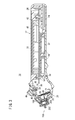
- FIG. 2 is a partially omitted enlarged cross-sectional view of the tip side of the component measuring apparatus shown in FIG. 1. It is a block diagram for demonstrating the control part which comprises the said component measuring apparatus. It is the flowchart which showed the procedure which measures a blood glucose level using the said component measuring apparatus.
- the component measuring apparatus 10 is a blood glucose meter that can be mounted with a measuring chip 200 at its tip and measures and displays the glucose concentration (blood glucose level) in the blood collected on the measuring chip 200. It is configured. First, the measurement chip 200 will be described.
- the measuring chip 200 is a so-called disposable product and is packaged in an individual package. As shown in FIGS. 2 and 5, the measuring chip 200 includes a chip main body 202 integrally formed of resin or the like, and a test paper 204 provided on the chip main body 202.
- the chip body 202 includes a plurality of (four in this embodiment) mounting claws 206 formed on the base end side, a disk-shaped base portion 208 provided on the distal end side of the mounting claws 206, and a base portion 208. And a suction projection 210 protruding from the approximate center toward the tip side.
- the plurality of mounting claws 206 are arranged at equal intervals in the circumferential direction on the outer peripheral portion of the base portion 208.
- the chip body 202 is formed with a small-diameter blood introduction path 212 that opens to the proximal end surface of the base portion 208 and the distal end surface of the suction protrusion 210.
- the test paper 204 is made of, for example, polyethersulfone and is fixed to the base end surface of the base portion 208.
- the reagent impregnated in the test paper 204 include color formers such as glucose oxidase (GOD), peroxidase (POD), 4-aminoantipyrine, and N-ethyl N- (2-hydroxy-3-sulfopropyl). It is done.
- the component measuring apparatus 10 will be described.
- the side on which the measurement chip 200 is attached is referred to as “front end side”, and the opposite side is referred to as “base end side”.
- the component measuring apparatus 10 includes an elongated casing 12, a main control board 14 disposed in the casing 12, and a liquid crystal provided on the main control board 14.
- the display 16 the ejector 18 disposed in the housing 12, the chip mounting portion 20 that is disposed in the opening on the front end side of the housing 12 and the measuring chip 200 is mounted, and the chip mounting portion 20.
- a photometric unit 22 arranged.
- the casing 12 is formed in a rectangular parallelepiped shape whose base end portion and intermediate portion can be easily gripped by a user with one hand, and the tip end portion is formed narrow. Has been.
- the housing 12 is made of resin or the like, and includes a first case 24 formed in a U-shaped cross section and a second case 26 fixed to the first case 24.
- the first case 24 includes a battery housing portion 30 that houses a plurality of (two in this embodiment) batteries 28 and a battery lid 32 that is detachably provided on the battery housing portion 30.
- a button-type battery is used as the battery 28, but it is needless to say that a round dry battery, a square dry battery, or a secondary battery may be used as the battery 28.
- each of the pair of operation buttons 34 is disposed are arranged side by side along the width direction of the second case 26.
- the display screen of the liquid crystal display 16 can be operated by a user or the like operating each operation button 34.
- each operation button 34 does not function as a power button. That is, in this embodiment, the component measuring apparatus 10 does not include a power button.
- An opening window 38 in which the liquid crystal display 16 is disposed is formed substantially at the center of the second case 26.
- a liquid crystal cover 40 is attached to the opening window 38 so as to cover the liquid crystal display 16.
- a protective panel 42 that covers the pair of operation buttons 34 and the liquid crystal cover 40 is attached to the second case 26.
- a long hole 48 into which the leg 46 of the ejector operation unit 44 is slidably inserted is formed at the tip of the second case 26.
- the ejector operation unit 44 is connected to the ejector 18 and is formed in a shape that is easy for a user or the like to operate with fingers.
- the long hole 48 extends along the longitudinal direction of the housing 12, and the ejector operation unit 44 and the ejector 18 can slide with respect to the housing 12 along the longitudinal direction.
- the main control board 14 is fixed to the second case 26 by a plurality of screw members 50 (see FIG. 3).
- a predetermined wiring circuit is formed on the main control board 14 by printing.
- the ejector 18 is integrally formed of resin or the like, and is in contact with the measuring chip 200 connected to the fixing portion 52 provided in the ejector operation portion 44 and the distal end side of the fixing portion 52.
- the fixing portion 52 is a plate member extending along the longitudinal direction of the housing 12, and a screw member 56 for fixing the ejector 18 to the ejector operation portion 44 on the base end side (see FIG. 3).
- a plurality of (two in the present embodiment) insertion holes 58 through which are inserted are arranged along the width direction of the fixed portion 52.
- the notch 60 is provided with a coil spring (spring member, biasing member, elastic member) 62 for biasing the ejector 18 toward the proximal end with respect to the chip mounting portion 20.
- a protrusion 66 is formed on the spring support wall 64 that constitutes.
- the extruding part 54 has a shape such that a part of the cylindrical body is cut out along the axial direction.
- the distal end surface of the pushing portion 54 faces the proximal end surfaces of the plurality of mounting claws 206 that constitute the measuring chip 200.
- the chip mounting portion 20 is integrally formed of resin or the like, and has a rectangular cylindrical base 68 disposed in the opening on the distal end side of the housing 12, and a cylindrical portion 70 that continues to the distal end side of the base 68.
- the width dimension of the base portion 68 is smaller than the outer diameter of the cylindrical portion 70.
- a protrusion 72 (see FIG. 5) is formed in a portion of the base portion 68 that faces the protrusion 66 of the ejector 18 so that the distal end side of the coil spring 62 is fitted.
- an annular locking portion 74 that locks the plurality of mounting claws 206 of the measuring chip 200 is formed.
- the photometry unit 22 protrudes toward the front end side from the sub-control board 76 electrically connected to the main control board 14, a plate-like board arrangement part 78 provided with the sub-control board 76, and the board arrangement part 78. And a cylindrical light guide 80.
- the sub-control board 76 has a plurality of (two in this embodiment) insertion holes 84 through which screw members 82 for fixing the sub-control board 76 to the board placement portion 78 are inserted.
- the sub-control board 76 irradiates the test paper 204 with the first light emitting element 85 that irradiates the test paper 204 with light having the first wavelength and the light having the second wavelength different from the first wavelength.
- a second light emitting element 86 for detecting the reflected light guided from the test paper 204 and a light receiving element 88 for detecting (receiving) the light are mounted.
- a light emitting diode (LED) is used as the first light emitting element 85 and the second light emitting element 86, and a photodiode (PD) is used as the light receiving element 88. Further, a through hole 90 is formed between the first light emitting element 85 and the second light emitting element 86 and the light receiving element 88 in the sub-control board 76.
- LED light emitting diode
- PD photodiode
- the substrate placement portion 78 and the light guide portion 80 are integrally formed of resin or the like.
- a plurality of (two in this embodiment) insertion holes 94 are formed in the substrate placement portion 78 through which screw members 92 for fixing the photometry portion 22 to the chip mounting portion 20 are inserted.
- the light guide unit 80 is located inside the extrusion unit 54 of the ejector 18. That is, the push-out portion 54 of the ejector 18 is disposed between the chip mounting portion 20 and the light guide portion 80. Thereby, the component measuring apparatus 10 can be comprised compactly.
- the light guide portion 80 is formed with a partition wall 100 that extends along the axial direction and partitions the light guide portion 80 into an irradiation light path 96 and a reflection light path 98.
- a base end portion of the partition wall 100 is located in the through hole 90 of the sub control board 76.
- the lens 102 is inserted and held in the front end side opening of the light guide 80.
- the lens 102 includes an irradiation lens 104 that condenses the light guided from the irradiation light path 96 onto the test paper 204, and a light guide lens 106 that condenses the reflected light guided from the test paper 204 onto the light receiving element 88. Yes.
- An O-ring 108 is interposed between the lens 102 and the light guide unit 80.
- the component measurement apparatus 10 further includes a power supply unit 110, a storage unit 112, and a control unit 114.
- the power supply unit 110 supplies the power of each battery 28 to the control unit 114.
- the storage unit 112 is configured as a ROM or RAM that stores a predetermined program.
- the control unit 114 is configured as a microcomputer that is mounted on the main control board 14 and performs predetermined processing.
- control unit 114 is provided with a mode switching control unit 116, a light emission control unit 118, a chip attachment determination unit 120, a usability determination unit 122, and a blood collection determination unit (body fluid collection determination unit) 124.
- the mode switching control unit 116 switches between the measurement mode and the standby mode (non-measurement mode) by controlling the power supply unit 110.
- the measurement mode is a state in which the power source of the component measuring apparatus 10 is turned on and the blood glucose level of the blood collected on the test paper 204 can be measured based on the reflected light detected by the light receiving element 88.
- the standby mode is a state in which the power consumption (average power consumption per unit time) is lower than that in the measurement mode, and the blood glucose level of the blood cannot be measured.
- the liquid crystal display 16 in the measurement mode, the liquid crystal display 16 is turned on, and in the standby mode, the liquid crystal display 16 is turned off and the photometry unit 22, the mode switching control unit 116, and the light emission control unit 118 can be driven.
- the light emission control unit 118 causes the first light emitting element 85 and the second light emitting element 86 to emit light.
- the chip mounting determination unit 120 determines whether or not the measurement chip 200 is mounted on the chip mounting unit 20 based on the reflected light detected by the light receiving element 88.
- the configuration in which the measurement chip 200 is not mounted includes a configuration in which the measurement chip 200 is mounted incompletely on the chip mounting portion 20 (for example, a part of the mounting nail of the measurement chip 200) Only 206 is locked to the annular locking portion 74 of the chip mounting portion 20 and the other mounting claw 206 is not locked to the annular locking portion 74.
- the usability determination unit 122 determines whether or not the measurement chip 200 is usable based on the reflected light detected by the light receiving element 88 during the measurement mode.
- the blood collection determination unit 124 determines whether blood is collected on the test paper 204 in a measurable state based on the reflected light detected by the light receiving element 88 during the measurement mode.
- the component measuring apparatus 10 is basically configured as described above, and blood glucose measurement using the component measuring apparatus 10 will be described next.
- the component measuring apparatus 10 is in a standby mode (see step S1 in FIG. 7).
- the light emission control unit 118 causes the first light emitting element 85 to emit light in pulses (step S2).
- the light emission control unit 118 intermittently emits light only from the first light emitting element 85.
- the light emission control unit 118 causes the first light emitting element 85 to emit light in pulses so that the light emission interval of the first light emitting element 85 in the standby mode is longer than the light emission interval of the first light emitting element 85 in the measurement mode.
- the power consumption in the standby mode is suppressed. Can do.
- the light emission control unit 118 uses the light emission intensity of the first light emitting element 85 in the measurement mode (the light emission intensity of the first light emitting element 85 in step S2).
- the first light emitting element 85 is caused to emit light so as to be smaller than the light emission intensity of the first light emitting element 85 in steps S5, S9, and S10 described later. Thereby, power consumption during the standby mode can be suitably suppressed.
- the light emitted from the first light emitting element 85 passes through the irradiation light path 96 and enters the irradiation lens 104 and is guided to the tip opening of the chip mounting portion 20.
- the measurement chip 200 is completely mounted on the chip mounting unit 20
- the light emitted from the first light emitting element 85 is condensed and irradiated onto the test paper 204 and reflected by the test paper 204.
- the light enters the light guide lens 106 as reflected light, passes through the reflected light path 98, and is condensed and irradiated to the light receiving element 88.
- the measurement chip 200 is not mounted on the chip mounting unit 20, the light emitted from the first light emitting element 85 is not detected by the light receiving element 88.
- the chip mounting determination unit 120 determines whether or not the measurement chip 200 is mounted on the chip mounting unit 20 based on the reflected light detected by the light receiving element 88 (step S3).
- the chip mounting determination unit 120 mounts the measurement chip 200 on the chip mounting unit 20 when the amount of reflected light (the amount of reflected light) detected by the light receiving element 88 exceeds a predetermined threshold. It is determined that the measurement chip 200 is not mounted on the chip mounting portion 20 when the amount of reflected light is equal to or less than the threshold value.
- the measurement chip 200 is mounted on the chip mounting portion 20.
- the light emitted from the first light emitting element 85 in a state where the measurement chip 200 is not mounted on the chip mounting unit 20 passes through the tip opening of the chip mounting unit 20 and is on the outside of the component measuring apparatus 10.
- reflected light may be detected by the light receiving element 88. Since the amount of reflected light detected in this way is equal to or less than the threshold value, it is possible to eliminate the concern that the measurement chip 200 is erroneously determined to be mounted on the chip mounting portion 20 in these cases.
- step S3 NO
- the process of step S3 is repeated.
- step S3 when the chip mounting determination unit 120 determines that the measurement chip 200 is mounted on the chip mounting unit 20 (step S3: YES), the mode switching control unit 116 switches from the standby mode to the measurement mode (Ste S4). Thereby, the component measuring apparatus 10 will be in the state which can measure a blood glucose level, when the liquid crystal display 16 lights.
- the usability determination unit 122 determines whether or not the measurement chip 200 mounted on the chip mounting unit 20 is usable (step S5). Specifically, for example, the light emission control unit 118 causes the first light emitting element 85 and the second light emitting element 86 to alternately emit pulses, and the usability determination unit 122 uses the reflected light amount detected by the light receiving element 88 as a test paper. It is determined whether or not blood or the like is attached to 204 (whether or not it is an unused measuring chip 200). Note that after the determination by the usability determination unit 122 is completed, the light emission control unit 118 stops the pulse light emission of the first light emitting element 85 and the second light emitting element 86.
- step S5 NO
- the control unit 114 displays NG on the liquid crystal display 16 (for example, “measurement chip NG”). Is displayed).
- step S7 the mode switching control unit 116 performs the process of step S3 described above. This is because it is necessary to mount the measurement chip 200 on the chip mounting unit 20 again.
- step S5 determines that the measurement chip 200 is usable
- the user or the like collects blood of the measurement subject (user or the like). (Step S8).
- control unit 114 may display “measurement chip OK” on the liquid crystal display 16, for example.
- the user or the like can grasp that the measurement chip 200 can be used by looking at the display on the liquid crystal display 16, and thus blood can be collected immediately.
- a finger is punctured with a dedicated puncture device (not shown), and a small amount of blood (eg, about 0.3 to 1.5 ⁇ L) is allowed to flow out onto the skin. Then, the tip of the suction protrusion 210 of the measuring chip 200 is brought into contact with (spotted on) the blood that has flowed out of the fingertip.
- a dedicated puncture device not shown
- a small amount of blood eg, about 0.3 to 1.5 ⁇ L
- blood is taken into the blood introduction path 212 of the measuring chip 200 and sucked to the proximal end by capillary action.
- the sucked blood soaks into the test paper 204 and diffuses (deploys) outward in the radial direction of the test paper 204.
- the glucose in the blood and the coloring reagent contained in the test paper 204 start to react, and the test paper 204 is colored according to the amount of glucose.
- the blood collection determination unit 124 determines whether blood has been collected in the measurement chip 200 in a state where the blood glucose level can be measured (step S9). That is, the blood collection determination unit 124 determines whether or not the amount of blood spotting and blood deployment are good (appropriate) based on the reflected light detected by the light receiving element 88.
- the light emission control unit 118 causes the first light emitting element 85 and the second light emitting element 86 to alternately emit pulses, and the blood collection determination unit 124 determines the amount of blood spotted based on the amount of reflected light detected by the light receiving element 88. And determining whether blood deployment is good. Note that after the determination by the blood collection determination unit 124 is completed, the light emission control unit 118 stops the pulse light emission of the first light emitting element 85 and the second light emitting element 86.
- step S9 NO
- the control unit 114 displays NG on the liquid crystal display 16 (for example, (Displayed as “blood spot NG” or “blood spread NG”) (step S6). Then, after switching from the measurement mode to the standby mode (step S7), the mode switching control unit 116 performs the process of step S3 described above.
- the component measurement apparatus 10 measures the measurement chip 200.
- the blood glucose level in the collected blood is measured (step S10).
- the light emission control unit 118 causes the first light emitting element 85 and the second light emitting element 86 to alternately emit light
- the control unit 114 measures the color intensity of the test paper 204 based on the amount of reflected light detected by the light receiving element 88. To do. Time measurement is started from the time when blood soaks into the test paper 204 and the amount of reflected light changes greatly, and the blood sugar level is calculated based on the amount of reflected light after a predetermined time has elapsed.
- the color produced by the reaction between the coloring reagent and glucose is detected by the light emitted from the first light emitting element 85, and the color density according to the amount of glucose is measured. Further, red blood cells are detected by light emitted from the second light emitting element 86, and the red density of the red blood cells is measured. Then, the glucose value obtained from the color concentration is corrected using the hematocrit value obtained from the red concentration, and the blood glucose level is obtained.
- control unit 114 displays the measured blood glucose level on the liquid crystal display 16 (step S11). Thereafter, the user or the like removes the measuring chip 200 from the chip mounting part 20 by sliding the ejector operation part 44 to the tip side (step S12).
- the mode switching control unit 116 switches from the measurement mode to the standby mode (step S13). As a result, the liquid crystal display 16 is turned off. At this stage, the current flowchart ends.
- the test of the measuring chip 200 from the first light emitting element 85 is performed when the measuring chip 200 is mounted on the chip mounting portion 20.
- the reflected light of the light irradiated on the paper 204 is detected by the light receiving element 88.
- the mode switching control unit 116 switches from the standby mode. Since the measurement mode is switched, the standby mode can be automatically switched to the measurement mode when the measurement chip 200 is mounted on the chip mounting unit 20. Thereby, it is not necessary to provide a power button on the component measuring apparatus 10. Therefore, the configuration of the component measuring apparatus 10 can be simplified.
- the component measuring apparatus 10 is provided with a power button, when the measurement chip 200 is mounted on the chip mounting unit 20, the standby mode is automatically switched to the measurement mode. Can be omitted. Thereby, the operation of the component measuring apparatus 10 is simplified, and an operation error (forgetting to press the power button) by the user or the like can be prevented, so that the burden on the user or the like can be reduced.
- the first light emitting element 85 having the first wavelength and the second light emitting element 86 having the second wavelength different from the first wavelength are provided.
- the blood glucose level can be measured with high accuracy using light. Further, the determination by the usability determination unit 122 and the blood collection determination unit 124 can be performed with high accuracy.
- the first light emitting element 85 since the first light emitting element 85 emits light intermittently during the standby mode, power consumption can be reduced compared to the case where the first light emitting element 85 emits light continuously. it can.
- the light emission control unit 118 emits light from the first light emitting element 85 when the light emission interval of the first light emitting element 85 in the standby mode (the light emission interval of the first light emitting element 85 in step S2) is in the measurement mode.
- the first light emitting element 85 emits light so as to be longer than the interval (the light emitting interval of the first light emitting element 85 in each of steps S5, S9, and S10).
- the power consumption in the standby mode is suppressed. Can do.
- the mode switching control unit 116 automatically switches from the measurement mode to the standby mode after a predetermined time elapses after the blood glucose level measurement is completed. Electric power can be reduced.
- the mode switching control unit 116 switches from the measurement mode to the standby mode when the usability determining unit 122 determines that the measuring chip 200 is unusable, so that the measuring chip 200 is changed to the chip mounting unit 20. It is possible to reduce the power consumption until it is mounted again.
- the mode switching control unit 116 determines that the blood spotting amount or blood deployment of the measurement chip 200 is not good (no blood is collected in the measurement chip 200 in a state where the blood sugar level can be measured), and the blood collection determination unit When the determination is made at 124, the measurement mode is switched to the standby mode, so that power consumption until the measurement chip 200 is mounted on the chip mounting unit 20 again can be suppressed.
- the light emission control unit 118 may cause only the second light emitting element 86 to emit light during the standby mode. Even in this case, power consumption during the standby mode can be suitably suppressed.
- the component measuring apparatus may be any device that measures a predetermined component of a body fluid, and is not limited to a blood glucose meter that measures a blood glucose level.
Landscapes
- Health & Medical Sciences (AREA)
- Life Sciences & Earth Sciences (AREA)
- Physics & Mathematics (AREA)
- Pathology (AREA)
- General Health & Medical Sciences (AREA)
- Molecular Biology (AREA)
- Medical Informatics (AREA)
- Public Health (AREA)
- Biomedical Technology (AREA)
- Heart & Thoracic Surgery (AREA)
- Biophysics (AREA)
- Optics & Photonics (AREA)
- Surgery (AREA)
- Animal Behavior & Ethology (AREA)
- Emergency Medicine (AREA)
- Engineering & Computer Science (AREA)
- Veterinary Medicine (AREA)
- Chemical & Material Sciences (AREA)
- Analytical Chemistry (AREA)
- Biochemistry (AREA)
- General Physics & Mathematics (AREA)
- Immunology (AREA)
- Investigating Or Analysing Materials By The Use Of Chemical Reactions (AREA)
Description
本発明は、測定用チップに採取された体液の所定成分を測定する成分測定装置に関する。
従来、血液や尿等の体液中の生体成分を検出して、その成分量や性質等を測定する成分測定装置が広汎に利用されている。
この種の成分測定装置を用いて血糖値を測定する場合、例えば、成分測定装置を構成するチップ装着部に対して使い捨ての測定用チップを装着し、前記測定用チップの試験紙に血液を染み込ませ、該試験紙に染み込んだ血液の血糖値を測定する(例えば、特開2011-64596号公報参照)。
上述した従来技術に係る成分測定装置では、該成分測定装置の電源ボタンをオンに操作することによって、成分測定装置の消費電力(単位時間当たりの平均消費電力)の少ない待機モードから該成分測定装置の電源がオン状態である測定モードに切り替えた後、測定用チップをチップ装着部に装着する操作を行う必要がある。そのため、特に、血糖値を1日に数回(例えば、4回)測定する必要のある糖尿病患者等にとっては、これら操作が負担になり易い。
また、例えば、前記電源ボタンをオンに操作することなく測定用チップをチップ装着部に装着して該測定用チップに血液を点着してしまうこともあり、この場合、該測定用チップを新しいものに取り替えなければならないため、血糖値の測定にかかる費用が高騰し、使用者等の負担になる。
本発明は、このような課題を考慮してなされたものであり、測定用チップをチップ装着部に装着したときに自動的に待機モードから測定モードに切り替えることができ、これによって成分測定装置の構成を簡素化することができ、使用者等の負担を軽減することができる成分測定装置を提供することを目的とする。
[1] 本発明に係る成分測定装置は、測定用チップに採取された体液の所定成分を測定する成分測定装置であって、前記測定用チップが装着されるチップ装着部と、前記チップ装着部に装着された前記測定用チップに光を照射するための発光素子と、前記発光素子から前記測定用チップに照射された前記光の反射光を検出する受光素子と、前記発光素子を発光させる発光制御部と、前記受光素子にて検出された前記反射光に基づいて前記チップ装着部に前記測定用チップが装着されたか否かを判定するチップ装着判定部と、前記成分測定装置の電源がオン状態である測定モードと該測定モードよりも消費電力の少ない待機モードとを切り替えるモード切替制御部と、を備え、前記待機モード中に、前記発光制御部が前記発光素子を発光させて前記測定用チップが前記チップ装着部に装着されたと前記チップ装着判定部が判定した場合に、前記モード切替制御部が前記待機モードから前記測定モードに切り替えることを特徴とする。
本発明に係る成分測定装置によれば、待機モード中に、発光素子を発光させているので、測定用チップをチップ装着部に装着した際に、発光素子から前記測定用チップに照射された光の反射光が受光素子にて検出される。そして、前記受光素子が検出した前記反射光に基づいて測定用チップがチップ装着部に装着されたとチップ装着判定部が判定した場合に、モード切替制御部が待機モードから測定モードに切り替えるので、前記測定用チップを前記チップ装着部に装着したときに自動的に待機モードから測定モードに切り替えることができる。これにより、成分測定装置に電源ボタンを省略することが可能となるため、該成分測定装置の構成を簡素化することができる。
また、成分測定装置に電源ボタンを設けた場合であっても、測定用チップをチップ装着部に装着した際に自動的に待機モードから測定モードに切り替わるため、該電源ボタンの操作を省略することができる。これにより、成分測定装置の操作が簡略化され、使用者等の操作ミス(電源ボタンの押し忘れ)を防止することができるため、使用者等の負担を軽減することができる。
[2] 上記の成分測定装置において、前記発光制御部は、前記待機モード中における前記発光素子の発光強度が前記測定モード中における前記発光素子の発光強度よりも小さくなるように前記発光素子を発光させてもよい。
このような装置によれば、待機モード中における発光素子の発光強度が測定モード中における前記発光素子の発光強度よりも小さいので、待機モード中の消費電力を好適に抑えることができる。
[3] 上記の成分測定装置において、前記発光素子として、第1の波長を有する光を出射する第1発光素子と、第1の波長とは異なる第2の波長を有する光を出射する第2発光素子とが用いられ、前記発光制御部は、前記待機モード中に、前記第1発光素子又は前記第2発光素子を発光させてもよい。
このような装置によれば、発光素子として第1発光素子と第2発光素子とが用いられるため、波長の異なる2種類の光を測定用チップに照射することができる。これにより、体液の所定成分の測定を高精度に行うことができる。また、待機モード中に、第1発光素子又は第2発光素子を発光させるため、待機モード中の消費電力を効率的に抑えることができる。
[4] 上記の成分測定装置において、前記発光制御部は、前記待機モード中に、前記発光素子を断続的に発光させてもよい。
このような装置によれば、待機モード中に発光素子を断続的に発光させるため、発光素子を連続的に発光させる場合と比較して、消費電力を少なくすることができる。
[5] 上記の成分測定装置において、前記発光制御部は、前記測定モード中に前記発光素子を断続的に発光させると共に、前記待機モード中における前記発光素子の発光間隔が前記測定モード中における前記発光素子の発光間隔よりも長くなるように前記発光素子を発光させてもよい。
このような装置によれば、待機モード中における発光素子の発光間隔が測定モード中における前記発光素子の発光間隔よりも長いため、例えば、待機モード中における発光素子の発光間隔と測定モード中における発光素子の発光間隔とが同一である場合と比較して、前記待機モード中の消費電力を抑えることができる。
[6] 上記の成分測定装置において、前記モード切替制御部は、前記体液の所定成分が測定されてから所定時間経過後に、前記測定モードから前記待機モードに切り替えてもよい。
このような装置によれば、モード切替制御部が、体液の所定成分の測定終了後、所定時間経過後に自動的に測定モードから待機モードに切り替えるので、使用者等の負担を一層軽減しつつ無駄な消費電力を削減することができる。
[7] 上記の成分測定装置において、前記測定モード中に、前記受光素子にて検出された前記反射光に基づいて前記測定用チップが使用可能であるか否かを判定する使用可否判定部をさらに備え、前記モード切替制御部は、前記測定用チップが使用不可であると前記使用可否判定部にて判定された場合に、前記測定モードから前記待機モードに切り替えてもよい。
このような装置によれば、モード切替制御部が、測定用チップが使用不可であると使用可否判定部にて判定された場合に測定モードから待機モードに切り替えるので、測定用チップがチップ装着部に再度装着されるまでの間の消費電力を抑えることができる。
[8] 上記の成分測定装置において、前記測定モード中に、前記受光素子にて検出された前記反射光に基づいて前記体液の所定成分を測定可能な状態で前記測定用チップに該体液が採取されたか否かを判定する体液採取判定部をさらに備え、前記モード切替制御部は、前記体液の所定成分を測定可能な状態で前記測定用チップに該体液が採取されていないと前記体液採取判定部にて判定された場合に、前記測定モードから前記待機モードに切り替えてもよい。
このような装置によれば、モード切替制御部が、体液の所定成分を測定可能な状態で測定用チップに該体液が採取されていないと体液採取判定部にて判定された場合に測定モードから待機モードに切り替えるので、測定用チップがチップ装着部に再度装着されるまでの間の消費電力を抑えることができる。
以下、本発明に係る成分測定装置について好適な実施形態を例示し、添付の図面を参照しながら説明する。
本実施形態に係る成分測定装置10は、その先端に測定用チップ200が装着可能であって、測定用チップ200に採取された血液中のグルコース濃度(血糖値)を測定及び表示する血糖計として構成されている。先ず、測定用チップ200について説明する。
測定用チップ200は、いわゆるディスポーザブル品であって、個包装体に包装されている。図2及び図5に示すように、測定用チップ200は、樹脂等で一体成形されたチップ本体202と、チップ本体202に設けられた試験紙204とを備える。
チップ本体202は、基端側に形成された複数(本実施形態では4つ)の装着爪206と、これら装着爪206の先端側に設けられた円板状のベース部208と、ベース部208の略中央から先端側に向けて突出した吸引突起210とを有している。
複数の装着爪206は、ベース部208の外周部において周方向に等間隔離間して配置されている。チップ本体202には、ベース部208の基端面と吸引突起210の先端面とに開口する細径の血液導入路212が形成されている。
試験紙204は、例えば、ポリエーテルスルホン等で構成されており、ベース部208の基端面に固着されている。試験紙204に含浸される試薬としては、例えば、グルコースオキシターゼ(GOD)、ペルオキシターゼ(POD)、4-アミノアンチピリン、N-エチルN-(2-ヒドロキシ-3-スルホプロピル)等の発色剤が挙げられる。
次に、本実施形態に係る成分測定装置10について説明する。なお、以下の説明では、成分測定装置10及びその構成要素に関し、測定用チップ200が装着される側を「先端側」と呼び、その反対側を「基端側」と呼ぶ。
図1~図3に示すように、成分測定装置10は、細長に構成された筐体12と、筐体12内に配設された主制御基板14と、主制御基板14に設けられた液晶ディスプレイ16と、筐体12内に配設されたイジェクタ18と、筐体12の先端側開口部に配設されて測定用チップ200が装着されるチップ装着部20と、チップ装着部20内に配設された測光部22とを備える。
図1から諒解されるように、筐体12は、その基端部及び中間部が使用者等によって片手で把持し易い大きさの直方体状に形成されると共に、その先端部が幅狭に形成されている。
筐体12は、樹脂等で構成されており、断面U字状に形成された第1ケース24と、第1ケース24に固着される第2ケース26とを有する。第1ケース24には、複数(本実施形態では2つ)の電池28を収容する電池収容部30と、電池収容部30に着脱可能に設けられた電池蓋32とを含む。本実施形態では、電池28としてボタン型電池が用いられているが、電池28として丸型乾電池、角型乾電池、又は二次電池を用いてもよいことは勿論である。
第2ケース26の基端側には、一対の操作ボタン34の各々が配設される一対の貫通孔36が第2ケース26の幅方向に沿って並んで配設されている。本実施形態では、使用者等が各操作ボタン34を操作することにより、液晶ディスプレイ16の表示画面が操作可能となっている。また、各操作ボタン34は、電源ボタンとしては機能しない。すなわち、本実施形態において、成分測定装置10は電源ボタンを備えていない。
第2ケース26の略中央には、液晶ディスプレイ16が配設される開口窓38が形成されている。開口窓38には、液晶ディスプレイ16を覆うようにして液晶カバー40が装着される。また、第2ケース26には、一対の操作ボタン34及び液晶カバー40を覆う保護パネル42が貼り付けられている。
第2ケース26の先端部には、イジェクタ操作部44の脚部46が摺動可能に挿入される長孔48が形成されている。イジェクタ操作部44は、イジェクタ18に接続されており、使用者等が手指によって操作し易い形状に形成されている。
長孔48は、筐体12の長手方向に沿って延びており、イジェクタ操作部44及びイジェクタ18は筐体12に対して前記長手方向に沿ってスライド動作が可能になっている。
主制御基板14は、複数のねじ部材50(図3参照)によって第2ケース26に対して固定されている。また、主制御基板14には、プリントによって所定の配線回路が形成されている。
図4及び図5に示すように、イジェクタ18は、樹脂等で一体成形されており、イジェクタ操作部44に設けられた固定部52と、固定部52の先端側に連なり測定用チップ200に接触可能な押出部54とを有する。固定部52は、筐体12の長手方向に沿って延在した板部材であって、その基端側には、イジェクタ18をイジェクタ操作部44に固定するためのねじ部材56(図3参照)が挿通する複数(本実施形態では2つ)の挿通孔58が固定部52の幅方向に沿って並設されている。
固定部52の幅方向略中央には、その先端から複数の挿通孔58の手前まで延びた切欠部60が形成されている。切欠部60には、チップ装着部20に対してイジェクタ18を基端側に付勢するためのコイルばね(ばね部材、付勢部材、弾性部材)62が配設され、切欠部60の基端を構成するばね支持壁64には、コイルばね62の基端側が外嵌される突起66が形成されている。
押出部54は、円筒体の一部をその軸線方向に沿って切り欠いたような形状を有している。押出部54の先端面は、測定用チップ200を構成する複数の装着爪206の基端面に対向する。
チップ装着部20は、樹脂等で一体的に成形されており、筐体12の先端側の開口部内に配設された四角筒状の基部68と、基部68の先端側に連なる円筒部70とを有する。
図4から諒解されるように、基部68の幅寸法は円筒部70の外径よりも小さい。基部68のうちイジェクタ18の突起66に対向する部位には、コイルばね62の先端側が外嵌される突起72(図5参照)が形成されている。円筒部70の内面には、測定用チップ200の複数の装着爪206が係止する環状係止部74が形成されている。
測光部22は、主制御基板14と電気的に接続された副制御基板76と、副制御基板76が設けられる板状の基板配置部78と、基板配置部78から先端側に向けて突出した筒状の導光部80とを有している。
副制御基板76には、該副制御基板76を基板配置部78に固定するためのねじ部材82が挿通する複数(本実施形態では2つ)の挿通孔84が形成されている。また、副制御基板76には、第1の波長を有する光を試験紙204に照射する第1発光素子85と、第1の波長とは異なる第2の波長を有する光を試験紙204に照射する第2発光素子86と、試験紙204から導かれた反射光を検出(受光)する受光素子88とが実装されている。
本実施形態では、第1発光素子85及び第2発光素子86として発光ダイオード(LED)が用いられ、受光素子88としてフォトダイオード(PD)が用いられる。また、副制御基板76のうち第1発光素子85及び第2発光素子86と受光素子88との間には貫通孔90が形成されている。
基板配置部78と導光部80とは、樹脂等で一体的に成形されている。基板配置部78には、測光部22をチップ装着部20に固定するためのねじ部材92が挿通する複数(本実施形態では2つ)の挿通孔94が形成されている。
導光部80は、イジェクタ18の押出部54の内方に位置している。すなわち、イジェクタ18の押出部54は、チップ装着部20と導光部80との間に配設されている。これにより成分測定装置10をコンパクトに構成することができる。
導光部80には、その軸線方向に沿って延在して導光部80内を照射光路96と反射光路98とに仕切る隔壁100が形成されている。隔壁100の基端部は、副制御基板76の貫通孔90に位置している。これにより、第1発光素子85又は第2発光素子86から出射した光を受光素子88が直接的に受光してしまうことを好適に防止することができる。
導光部80の先端側開口部内にはレンズ102が挿入保持されている。レンズ102は、照射光路96から導かれた光を試験紙204に集光する照射レンズ104と、試験紙204から導かれた反射光を受光素子88に集光する導光レンズ106とを含んでいる。レンズ102と導光部80との間にはOリング108が介設されている。
図6に示すように、成分測定装置10は、電源部110、記憶部112、及び制御部114をさらに備えている。電源部110は、各電池28の電力を制御部114に供給する。記憶部112は、所定のプログラムが記憶されたROMやRAMとして構成されている。制御部114は、上述した主制御基板14に実装されて所定の処理を実行するためのマイクロコンピュータとして構成されている。
また、制御部114には、モード切替制御部116、発光制御部118、チップ装着判定部120、使用可否判定部122、及び血液採取判定部(体液採取判定部)124が設けられている。
モード切替制御部116は、電源部110を制御することによって測定モードと待機モード(非測定モード)とを切り替える。ここで、測定モードとは、成分測定装置10の電源がオン状態であって、受光素子88にて検出された反射光に基づいて試験紙204に採取された血液の血糖値を測定可能な状態をいい、待機モードとは、測定モードよりも消費電力(単位時間当たりの平均消費電力)の少ない状態であって、前記血液の血糖値の測定を行うことができない状態をいう。
すなわち、測定モードでは、液晶ディスプレイ16が点灯しており、待機モードでは、液晶ディスプレイ16が消灯すると共に測光部22、モード切替制御部116、及び発光制御部118が駆動可能となっている。
発光制御部118は、第1発光素子85及び第2発光素子86を発光させる。チップ装着判定部120は、受光素子88が検出した反射光に基づいて測定用チップ200がチップ装着部20に装着されたか否かを判定する。
本実施形態において、測定用チップ200が装着されていない形態には、測定用チップ200がチップ装着部20に不完全なまま装着されている形態(例えば、測定用チップ200の一部の装着爪206のみがチップ装着部20の環状係止部74に係止されて他の装着爪206は環状係止部74に係止されていないような形態)を含む。
使用可否判定部122は、測定モード中に、受光素子88にて検出された反射光に基づいて測定用チップ200が使用可能であるか否かを判定する。血液採取判定部124は、測定モード中に、受光素子88にて検出された反射光に基づいて試験紙204に血液が測定可能な状態で採取されたか否かを判定する。
本実施形態に係る成分測定装置10は、基本的には以上のように構成されるものであり、次に前記成分測定装置10を用いた血糖値の測定について説明する。
初期状態において、成分測定装置10は待機モードとなっている(図7のステップS1参照)。この待機モードでは、発光制御部118は第1発光素子85をパルス発光させる(ステップS2)。換言すれば、発光制御部118は、第1発光素子85のみから光を断続的に出射する。これにより、第1発光素子85を連続的に発光させた場合と比較して、待機モード中における消費電力を効率的に抑えることができる。
また、発光制御部118は、待機モード中における第1発光素子85の発光間隔が測定モード中における第1発光素子85の発光間隔よりも長くなるように第1発光素子85をパルス発光させる。これにより、例えば、待機モード中における第1発光素子85の発光間隔と測定モード中における第1発光素子85の発光間隔とが同一である場合と比較して、待機モード中の消費電力を抑えることができる。
本実施形態において、発光制御部118は、待機モード中の第1発光素子85の発光強度(ステップS2における第1発光素子85の発光強度)が測定モード中の第1発光素子85の発光強度(後述するステップS5、S9、及びS10における第1発光素子85の発光強度)よりも小さくなるように第1発光素子85を発光させる。これにより、待機モード中の消費電力を好適に抑えることができる。
第1発光素子85から出射した光は、照射光路96を通過して照射レンズ104に入射されチップ装着部20の先端開口部に導かれる。このとき、測定用チップ200がチップ装着部20に完全に装着されている場合には、第1発光素子85から出射した光は、試験紙204に集光照射され、該試験紙204で反射されて反射光として導光レンズ106に入射され、反射光路98を通過して受光素子88に集光照射される。一方、測定用チップ200がチップ装着部20に全く装着されていない場合には、第1発光素子85から出射した光は、受光素子88にて検出されることはない。
また、チップ装着判定部120は、受光素子88にて検出された反射光に基づいて測定用チップ200がチップ装着部20に装着されたか否かを判定する(ステップS3)。
具体的には、例えば、チップ装着判定部120は、受光素子88が検出した反射光の光量(反射光量)が所定の閾値を超えている場合に測定用チップ200がチップ装着部20に装着されていると判定し、前記反射光量が前記閾値以下である場合に測定用チップ200がチップ装着部20に装着されていないと判定する。
これにより、測定用チップ200がチップ装着部20に装着されたか否かを確実に判定することができる。すなわち、測定用チップ200がチップ装着部20に装着されていない状態で第1発光素子85から出射された光がチップ装着部20の先端開口部を通過して成分測定装置10の外側にある壁等で反射した場合や、測定用チップ200がチップ装着部20に不完全な状態で装着された場合には、受光素子88にて反射光が検出されることがあるが、該受光素子88にて検出される反射光量は前記閾値以下となるので、これらの場合に測定用チップ200がチップ装着部20に装着されたと誤判定される懸念を排除することができる。
測定用チップ200がチップ装着部20に装着されていないとチップ装着判定部120にて判定された場合(ステップS3:NO)には、ステップS3の処理を繰り返し行う。
一方、測定用チップ200がチップ装着部20に装着されたとチップ装着判定部120にて判定された場合(ステップS3:YES)には、モード切替制御部116は、待機モードから測定モードに切り替える(ステップS4)。これにより、成分測定装置10は、液晶ディスプレイ16が点灯して血糖値を測定可能な状態となる。
続いて、使用可否判定部122は、チップ装着部20に装着された測定用チップ200が使用可能であるか否かを判定する(ステップS5)。具体的には、例えば、発光制御部118が第1発光素子85及び第2発光素子86を交互にパルス発光させ、使用可否判定部122が受光素子88にて検出された反射光量に基づき試験紙204に血液等が付着しているか否か(未使用の測定用チップ200であるか否か)を判定する。なお、使用可否判定部122による判定が終了した後、発光制御部118は第1発光素子85及び第2発光素子86のパルス発光を停止する。
測定用チップ200が使用不能であると使用可否判定部122にて判定された場合(ステップS5:NO)には、制御部114は、液晶ディスプレイ16にNG表示(例えば、「測定用チップNG」と表示)をする。
そして、モード切替制御部116は、測定モードから待機モードに切り替えた(ステップS7)後、上述したステップS3の処理を行う。測定用チップ200をチップ装着部20に再度装着する必要があるからである。
一方、測定用チップ200が使用可能であると使用可否判定部122にて判定された場合(ステップS5:YES)には、使用者等は、測定対象者(使用者等)の血液を採取する(ステップS8)。
このとき、制御部114は、例えば、液晶ディスプレイ16に「測定用チップOK」と表示してもよい。この場合、使用者等は、液晶ディスプレイ16の表示を見て、測定用チップ200が使用可能であることを把握することができるので、血液の採取を直ぐに行うことができる。
血液の採取では、先ず、手指を専用の図示しない穿刺器具で穿刺し、皮膚上に少量(例えば、0.3~1.5μL程度)の血液を流出させる。そして、指先から流出した血液に、測定用チップ200の吸引突起210の先端を接触させる(点着させる)。
そうすると、血液が、測定用チップ200の血液導入路212内に取り込まれ、毛細管現象によって基端に吸引される。吸引された血液は試験紙204に染み込み、試験紙204の径方向外側へ向かって拡散(展開)する。このとき、血液中のブドウ糖と試験紙204に含まれている発色試薬とが反応を開始し、ブドウ糖の量に応じて試験紙204が呈色する。
続いて、血液採取判定部124は、血糖値を測定可能な状態で測定用チップ200に血液が採取されたか否かを判定する(ステップS9)。すなわち、血液採取判定部124は、受光素子88にて検出される反射光に基づいて血液点着量及び血液展開が良好(適当)か否かを判定する。
具体的には、発光制御部118が第1発光素子85及び第2発光素子86を交互にパルス発光させ、血液採取判定部124が受光素子88にて検出された反射光量に基づき血液点着量及び血液展開が良好か否かを判定する。なお、血液採取判定部124による判定が終了した後、発光制御部118は第1発光素子85及び第2発光素子86のパルス発光を停止する。
血糖値を測定可能な状態で測定用チップ200に血液が採取されていないと血液採取判定部124が判定した場合(ステップS9:NO)には、制御部114は液晶ディスプレイ16にNG表示(例えば、「血液点着量NG」又は「血液展開NG」と表示)する(ステップS6)。そして、モード切替制御部116は、測定モードから待機モードに切り替えた(ステップS7)後、上述したステップS3の処理を行う。
一方、血糖値を測定可能な状態で測定用チップ200に血液が採取されていると血液採取判定部124が判定した場合(ステップS9:YES)には、成分測定装置10は、測定用チップ200に採取された血液中の血糖値を測定する(ステップS10)。
すなわち、発光制御部118が第1発光素子85及び第2発光素子86を交互にパルス発光させ、制御部114が受光素子88にて検出された反射光量に基づき試験紙204の呈色強度を測定する。そして、血液が試験紙204に染み込んで反射光量が大きく変化した時点から計時を開始し、所定時間経過後の反射光量に基づいて血糖値が算出される。
具体的には、第1発光素子85から出射した光によって発色試薬とブドウ糖との反応で生じた色素を検出し、ブドウ糖の量に応じた呈色濃度を測定する。また、第2発光素子86から出射した光によって赤血球を検出し、赤血球の赤色濃度を測定する。そして、呈色濃度から得られるグルコース値を赤色濃度から得られるヘマトクリット値を用いて補正し、血糖値を求める。
次に、制御部114は、測定した血糖値を液晶ディスプレイ16に表示する(ステップS11)。その後、使用者等は、イジェクタ操作部44を先端側にスライドさせることにより測定用チップ200をチップ装着部20から取り外す(ステップS12)。
また、モード切替制御部116は、測定モードから待機モードに切り替える(ステップS13)。これにより、液晶ディスプレイ16が消灯する。この段階で今回のフローチャートが終了する。
本実施形態によれば、待機モード中に第1発光素子85を発光させているので、測定用チップ200をチップ装着部20に装着した際に、第1発光素子85から測定用チップ200の試験紙204に照射された光の反射光が受光素子88にて検出される。
そして、受光素子88が検出した反射光に基づいてチップ装着判定部120にて測定用チップ200がチップ装着部20に装着されていると判定された場合に、モード切替制御部116が待機モードから測定モードに切り替えるので、測定用チップ200をチップ装着部20に装着したときに自動的に待機モードから測定モードに切り替えることができる。これにより、成分測定装置10に電源ボタンを設ける必要がない。よって、成分測定装置10の構成を簡素化することができる。
また、成分測定装置10に電源ボタンを設けた場合であっても、測定用チップ200をチップ装着部20に装着した際に自動的に待機モードから測定モードに切り替わるため、該電源ボタンの操作を省略することができる。これにより、成分測定装置10の操作が簡略化され、使用者等の操作ミス(電源ボタンの押し忘れ)を防止することができるため、使用者等の負担を軽減することができる。
本実施形態によれば、第1の波長を有する第1発光素子85と、第1の波長と異なる第2の波長を有する第2発光素子86が設けられているので、波長の異なる2種類の光を用いて血糖値の測定を高精度に行うことができる。また、使用可否判定部122及び血液採取判定部124の判定についても高精度に行うことが可能となる。
また、本実施形態では、待機モード中に第1発光素子85を断続的に発光させているので、第1発光素子85を連続的に発光させる場合と比較して、消費電力を少なくすることができる。
さらに、本実施形態では、発光制御部118は、待機モード中における第1発光素子85の発光間隔(ステップS2における第1発光素子85の発光間隔)が測定モード中における第1発光素子85の発光間隔(ステップS5、ステップS9、及びステップS10の各々における第1発光素子85の発光間隔)よりも長くなるように第1発光素子85を発光させている。
これにより、例えば、待機モード中における第1発光素子85の発光間隔と測定モード中における第1発光素子85の発光間隔とが同一である場合と比較して、待機モード中の消費電力を抑えることができる。
本実施形態によれば、モード切替制御部116が、血糖値の測定終了後、所定時間経過後に自動的に測定モードから待機モードに切り替えるので、使用者等の負担を一層軽減しつつ無駄な消費電力を削減することができる。
また、モード切替制御部116が、測定用チップ200が使用不可であると使用可否判定部122にて判定された場合に測定モードから待機モードに切り替えるので、測定用チップ200がチップ装着部20に再度装着されるまでの間の消費電力を抑えることができる。
さらに、モード切替制御部116が、測定用チップ200の血液点着量又は血液展開が良好でない(血糖値を測定可能な状態で測定用チップ200に血液が採取されていない)と血液採取判定部124にて判定された場合に測定モードから待機モードに切り替えるので、測定用チップ200がチップ装着部20に再度装着されるまでの間の消費電力を抑えることができる。
本実施形態は上述した構成に限定されない。例えば、発光制御部118は、待機モード中に、第2発光素子86のみを発光させても構わない。この場合であっても、待機モード中の消費電力を好適に抑えることができる。
上記において、本発明について好適な実施形態を挙げて説明したが、本発明は前記実施形態に限定されるものではなく、本発明の要旨を逸脱しない範囲において、種々の改変が可能なことは言うまでもない。
例えば、本発明に係る成分測定装置は、体液の所定成分を測定するものであればよく、血糖値を測定する血糖計に限られない。
Claims (8)
- 測定用チップ(200)に採取された体液の所定成分を測定する成分測定装置(10)であって、
前記測定用チップ(200)が装着されるチップ装着部(20)と、
前記チップ装着部(20)に装着された前記測定用チップ(200)に光を照射するための発光素子(85、86)と、
前記発光素子(85、86)から前記測定用チップ(200)に照射された前記光の反射光を検出する受光素子(88)と、
前記発光素子(85、86)を発光させる発光制御部(118)と、
前記受光素子(88)にて検出された前記反射光に基づいて前記チップ装着部(20)に前記測定用チップ(200)が装着されたか否かを判定するチップ装着判定部(120)と、
前記成分測定装置(10)の電源がオン状態である測定モードと該測定モードよりも消費電力の少ない待機モードとを切り替えるモード切替制御部(116)と、を備え、
前記待機モード中に、前記発光制御部(118)が前記発光素子(85、86)を発光させて前記測定用チップ(200)が前記チップ装着部(20)に装着されたと前記チップ装着判定部(120)が判定した場合に、前記モード切替制御部(116)が前記待機モードから前記測定モードに切り替えることを特徴とする成分測定装置(10)。 - 請求項1記載の成分測定装置(10)において、
前記発光制御部(118)は、前記待機モード中における前記発光素子(85、86)の発光強度が前記測定モード中における前記発光素子(85)の発光強度よりも小さくなるように前記発光素子(85、86)を発光させることを特徴とする成分測定装置(10)。 - 請求項1記載の成分測定装置(10)において、
前記発光素子(85、86)として、第1の波長を有する光を出射する第1発光素子(85)と、第1の波長とは異なる第2の波長を有する光を出射する第2発光素子(86)とが用いられ、
前記発光制御部(118)は、前記待機モード中に、前記第1発光素子(85)又は前記第2発光素子(86)を発光させることを特徴とする成分測定装置(10)。 - 請求項1記載の成分測定装置(10)において、
前記発光制御部(118)は、前記待機モード中に、前記発光素子(85、86)を断続的に発光させることを特徴とする成分測定装置(10)。 - 請求項4記載の成分測定装置(10)において、
前記発光制御部(118)は、前記測定モード中に前記発光素子(85、86)を断続的に発光させると共に、前記待機モード中における前記発光素子(85、86)の発光間隔が前記測定モード中における前記発光素子(85、86)の発光間隔よりも長くなるように前記発光素子(85、86)を発光させることを特徴とする成分測定装置(10)。 - 請求項1記載の成分測定装置(10)において、
前記モード切替制御部(116)は、前記体液の所定成分が測定されてから所定時間経過後に、前記測定モードから前記待機モードに切り替えることを特徴とする成分測定装置(10)。 - 請求項1記載の成分測定装置(10)において、
前記測定モード中に、前記受光素子(88)にて検出された前記反射光に基づいて前記測定用チップ(200)が使用可能であるか否かを判定する使用可否判定部(122)をさらに備え、
前記モード切替制御部(116)は、前記測定用チップ(200)が使用不可であると前記使用可否判定部(122)にて判定された場合に、前記測定モードから前記待機モードに切り替えることを特徴とする成分測定装置(10)。 - 請求項1記載の成分測定装置(10)において、
前記測定モード中に、前記受光素子(88)にて検出された前記反射光に基づいて前記体液の所定成分を測定可能な状態で前記測定用チップ(200)に該体液が採取されたか否かを判定する体液採取判定部(124)をさらに備え、
前記モード切替制御部(116)は、前記体液の所定成分を測定可能な状態で前記測定用チップ(200)に該体液が採取されていないと前記体液採取判定部(124)にて判定された場合に、前記測定モードから前記待機モードに切り替えることを特徴とする成分測定装置(10)。
Priority Applications (1)
| Application Number | Priority Date | Filing Date | Title |
|---|---|---|---|
| PCT/JP2012/073890 WO2014045346A1 (ja) | 2012-09-19 | 2012-09-19 | 成分測定装置 |
Applications Claiming Priority (1)
| Application Number | Priority Date | Filing Date | Title |
|---|---|---|---|
| PCT/JP2012/073890 WO2014045346A1 (ja) | 2012-09-19 | 2012-09-19 | 成分測定装置 |
Publications (1)
| Publication Number | Publication Date |
|---|---|
| WO2014045346A1 true WO2014045346A1 (ja) | 2014-03-27 |
Family
ID=50340706
Family Applications (1)
| Application Number | Title | Priority Date | Filing Date |
|---|---|---|---|
| PCT/JP2012/073890 Ceased WO2014045346A1 (ja) | 2012-09-19 | 2012-09-19 | 成分測定装置 |
Country Status (1)
| Country | Link |
|---|---|
| WO (1) | WO2014045346A1 (ja) |
Cited By (4)
| Publication number | Priority date | Publication date | Assignee | Title |
|---|---|---|---|---|
| WO2018123676A1 (ja) * | 2016-12-27 | 2018-07-05 | アルプス電気株式会社 | センサモジュールおよび生体関連情報表示システム |
| JP2019042004A (ja) * | 2017-08-31 | 2019-03-22 | 富士ゼロックス株式会社 | 光学測定装置及び光学測定プログラム |
| JPWO2021166510A1 (ja) * | 2020-02-20 | 2021-08-26 | ||
| WO2021166471A1 (ja) * | 2020-02-20 | 2021-08-26 | テルモ株式会社 | 成分測定装置、成分測定装置セット及び情報処理方法 |
Citations (3)
| Publication number | Priority date | Publication date | Assignee | Title |
|---|---|---|---|---|
| WO2008120614A1 (ja) * | 2007-03-30 | 2008-10-09 | Terumo Kabushiki Kaisha | 体液成分測定装置 |
| JP2010217074A (ja) * | 2009-03-18 | 2010-09-30 | Panasonic Corp | 免疫定量測定システム |
| JP2011064596A (ja) * | 2009-09-17 | 2011-03-31 | Terumo Corp | 血糖計 |
-
2012
- 2012-09-19 WO PCT/JP2012/073890 patent/WO2014045346A1/ja not_active Ceased
Patent Citations (3)
| Publication number | Priority date | Publication date | Assignee | Title |
|---|---|---|---|---|
| WO2008120614A1 (ja) * | 2007-03-30 | 2008-10-09 | Terumo Kabushiki Kaisha | 体液成分測定装置 |
| JP2010217074A (ja) * | 2009-03-18 | 2010-09-30 | Panasonic Corp | 免疫定量測定システム |
| JP2011064596A (ja) * | 2009-09-17 | 2011-03-31 | Terumo Corp | 血糖計 |
Cited By (15)
| Publication number | Priority date | Publication date | Assignee | Title |
|---|---|---|---|---|
| WO2018123676A1 (ja) * | 2016-12-27 | 2018-07-05 | アルプス電気株式会社 | センサモジュールおよび生体関連情報表示システム |
| JPWO2018123676A1 (ja) * | 2016-12-27 | 2019-07-11 | アルプスアルパイン株式会社 | センサモジュールおよび生体関連情報表示システム |
| US11096592B2 (en) | 2016-12-27 | 2021-08-24 | Alps Alpine Co., Ltd. | Sensor module and biological information display system |
| JP2019042004A (ja) * | 2017-08-31 | 2019-03-22 | 富士ゼロックス株式会社 | 光学測定装置及び光学測定プログラム |
| US11534088B2 (en) | 2017-08-31 | 2022-12-27 | Fujifilm Business Innovation Corp. | Optical measuring apparatus and non-transitory computer readable medium |
| JP7024261B2 (ja) | 2017-08-31 | 2022-02-24 | 富士フイルムビジネスイノベーション株式会社 | 光学測定装置及び光学測定プログラム |
| JPWO2021166471A1 (ja) * | 2020-02-20 | 2021-08-26 | ||
| WO2021166510A1 (ja) * | 2020-02-20 | 2021-08-26 | テルモ株式会社 | 成分測定装置、成分測定装置セット及び情報処理方法 |
| WO2021166471A1 (ja) * | 2020-02-20 | 2021-08-26 | テルモ株式会社 | 成分測定装置、成分測定装置セット及び情報処理方法 |
| CN114729923A (zh) * | 2020-02-20 | 2022-07-08 | 泰尔茂株式会社 | 成分测定装置、成分测定装置组以及信息处理方法 |
| CN114729897A (zh) * | 2020-02-20 | 2022-07-08 | 泰尔茂株式会社 | 成分测定装置、成分测定装置组以及信息处理方法 |
| JPWO2021166510A1 (ja) * | 2020-02-20 | 2021-08-26 | ||
| US12188875B2 (en) | 2020-02-20 | 2025-01-07 | Terumo Kabushiki Kaisha | Component measurement apparatus, component measurement apparatus set, and information processing method |
| JP7617893B2 (ja) | 2020-02-20 | 2025-01-20 | テルモ株式会社 | 成分測定装置、成分測定装置セット及び情報処理方法 |
| JP7617894B2 (ja) | 2020-02-20 | 2025-01-20 | テルモ株式会社 | 成分測定装置、成分測定装置セット及び情報処理方法 |
Similar Documents
| Publication | Publication Date | Title |
|---|---|---|
| US10694984B2 (en) | Test method and test drive for analysing a body fluid | |
| JP5047194B2 (ja) | 血液検査装置 | |
| CN102439428B (zh) | 成分测定装置 | |
| EP2103256B1 (en) | Component measuring apparatus | |
| JP5043863B2 (ja) | 血液検査装置 | |
| WO2017127349A1 (en) | Mobile device based multi-analyte testing analyzer for use in medical diagnostic monitoring and screening | |
| JPH10318928A (ja) | 成分測定装置および成分測定用チップ | |
| JP6521946B2 (ja) | 成分測定装置 | |
| JP2007225615A (ja) | Rfid使用の検体測定計を較正する有用な方法 | |
| JP4871083B2 (ja) | 体液採取ユニット | |
| JP5514464B2 (ja) | 成分測定装置 | |
| JP3155842U (ja) | 成分測定装置 | |
| JP4897838B2 (ja) | 成分測定装置 | |
| JP2010236943A (ja) | 血糖値測定装置、血糖値測定方法及びプログラム | |
| EP4086627A1 (en) | Component measurement device, component measurement device set, and information processing method | |
| JP6184818B2 (ja) | 成分測定装置 | |
| JP3155843U (ja) | 温度センサ及び成分測定装置 | |
| JP2012078182A (ja) | 成分測定装置 | |
| JP5693639B2 (ja) | 血糖値測定装置 | |
| WO2014045343A1 (ja) | 成分測定装置 | |
| JP2004290477A (ja) | 成分測定装置および成分測定キット | |
| WO2013146065A1 (ja) | 成分測定装置 | |
| WO2014045347A1 (ja) | 成分測定装置 | |
| HK1167714B (zh) | 成份测定装置 |
Legal Events
| Date | Code | Title | Description |
|---|---|---|---|
| 121 | Ep: the epo has been informed by wipo that ep was designated in this application |
Ref document number: 12885077 Country of ref document: EP Kind code of ref document: A1 |
|
| NENP | Non-entry into the national phase |
Ref country code: DE |
|
| 122 | Ep: pct application non-entry in european phase |
Ref document number: 12885077 Country of ref document: EP Kind code of ref document: A1 |
|
| NENP | Non-entry into the national phase |
Ref country code: JP |