WO2014041916A1 - カーテンシールドエアバッグ装置の設置構造 - Google Patents
カーテンシールドエアバッグ装置の設置構造 Download PDFInfo
- Publication number
- WO2014041916A1 WO2014041916A1 PCT/JP2013/070886 JP2013070886W WO2014041916A1 WO 2014041916 A1 WO2014041916 A1 WO 2014041916A1 JP 2013070886 W JP2013070886 W JP 2013070886W WO 2014041916 A1 WO2014041916 A1 WO 2014041916A1
- Authority
- WO
- WIPO (PCT)
- Prior art keywords
- bag body
- airbag device
- curtain shield
- hook
- shield airbag
- Prior art date
- Legal status (The legal status is an assumption and is not a legal conclusion. Google has not performed a legal analysis and makes no representation as to the accuracy of the status listed.)
- Ceased
Links
Images



Classifications
-
- B—PERFORMING OPERATIONS; TRANSPORTING
- B60—VEHICLES IN GENERAL
- B60R—VEHICLES, VEHICLE FITTINGS, OR VEHICLE PARTS, NOT OTHERWISE PROVIDED FOR
- B60R21/00—Arrangements or fittings on vehicles for protecting or preventing injuries to occupants or pedestrians in case of accidents or other traffic risks
- B60R21/02—Occupant safety arrangements or fittings, e.g. crash pads
- B60R21/16—Inflatable occupant restraints or confinements designed to inflate upon impact or impending impact, e.g. air bags
- B60R21/20—Arrangements for storing inflatable members in their non-use or deflated condition; Arrangement or mounting of air bag modules or components
- B60R21/213—Arrangements for storing inflatable members in their non-use or deflated condition; Arrangement or mounting of air bag modules or components in vehicle roof frames or pillars
Definitions
- the present invention relates to an installation structure of a curtain shield airbag device installed in a vehicle.
- airbags are known as one of the occupant protection systems for automobiles.
- Such an airbag includes what is called a curtain shield airbag device.
- the curtain shield airbag device is inflated from a portion along the roof side rail at the time of an automobile side collision or an automobile rollover, and protects the head and neck of the driver's seat passenger, the passenger on the passenger seat, and the passenger on the rear seat.
- This curtain shield airbag device also includes a bag body and an inflator, like a general airbag.
- the bag body is formed in a bag shape, and the inflator generates an inflation fluid that flows into the bag body.
- This type of curtain shield airbag device is installed on the body frame according to the following procedure.
- a ceiling module vehicle ceiling
- a sun visor, an interior molding mall, an assist grip, and the like are assembled.
- the curtain shield airbag device is fixed to the pillar (see, for example, Japanese Patent Laid-Open Nos. 2000-198407 and 2009-67221). That is, the bag constituting the curtain shield airbag device is screwed to the pillar.
- the inflated and unfolded bag body hangs down from the roof side rail.
- the bag body that hangs down in this manner is supported by pillars of the vehicle body frame that are screw-fixed. Conventionally, in order to sufficiently support the bag body that hangs down in this manner, it has been considered that the bag body is screwed to the bracket of the assist grip.
- an installation structure for a curtain shield airbag device installed in a vehicle such as an automobile is provided.
- the curtain shield airbag device includes a bag body that is formed in a bag shape and into which inflation fluid flows and an inflator that generates inflation fluid that flows into the bag body.
- a ring-shaped hook portion formed so that the protruding shape of the grip support bracket fixed to the vehicle body frame can be inserted is provided on the upper portion of the bag body when inflated and deployed.
- the bag body is configured to be able to be suspended from the grip support bracket by hooking the hook portion through the protruding shape of the grip support bracket.
- the upper portion of the bag body when inflated and deployed has a hook portion, and the bag body can be suspended from the grip support bracket by hooking the hook portion.
- the bag body can be suspended and supported by the grip support bracket by the hooking portion. Therefore, the screw fixing member used for screw fixing the bag body can be eliminated, the number of parts can be reduced, and the installation cost of the curtain shield airbag device can be reduced. Further, the screw fixing work for fixing the bag body to the screw can be reduced, and the installation work can be simplified.
- the curtain shield airbag device is incorporated into the ceiling module body as part of a ceiling module assembled to the vehicle body frame.
- the curtain shield airbag device can be positioned and arranged with respect to the vehicle body frame at the same time that the ceiling module is assembled to the vehicle body frame. Therefore, in installing the curtain shield airbag device, installation work such as positioning work can be omitted, and the installation work can be simplified.
- a curtain shield airbag device includes a protector that receives support from the grip support bracket, and the protector is configured to inflate and deploy the bag body that is generated when the bag body is inflated and deployed. Support reaction force. According to the installation structure of the curtain shield airbag device, the bag body is inflated and deployed by the protector, and can be guided more accurately so that the bag body is in a predetermined inflated and deployed state.
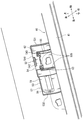
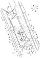
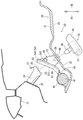
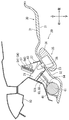
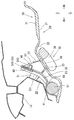
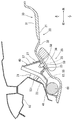
- FIG. 2 is an enlarged view of a rounded portion II in FIG. 1. It is a disassembled perspective view of a ceiling module. It is an enlarged view of the hook part of FIG. It is a perspective view which shows the assembly
- FIG. 7 is a sectional view taken along line VII-VII in FIG. 5.
- FIG. 6 is a sectional view taken along line VIII-VIII in FIG. 5.
- FIG. 6 is a sectional view taken along line IX-IX in FIG. 5.
- the ceiling module 30 forms the ceiling of an automobile as a vehicle.
- the vehicle in which the ceiling module 30 is disposed is a type of vehicle in which seats are provided in three rows in the front and rear. For this reason, the ceiling module 30 is provided with a sunroof structure or the like.
- the ceiling module 30 is assembled to the vehicle body frame 10 so as to form the ceiling of the vehicle.
- the ceiling module 30 generally includes a ceiling module body 31 and a curtain airbag 40.
- a curtain airbag 40 is assembled to the side portion of the ceiling module body 31.
- the curtain airbag 40 is incorporated in the ceiling module main body 31 as a part of the ceiling module 30 assembled to the vehicle body frame 10.
- the ceiling module body 31 is configured as a conventional ceiling module, and the molded ceiling 32 is equipped with module parts (not shown, for example, an overhead console, a room lamp, etc.).
- a sun visor not shown
- an interior molding not shown
- an assist grip 35 and the like are assembled.
- a vehicle body frame 10 shown in FIG. 3 or the like constitutes a framework of an automobile and includes a front pillar 11, an A pillar 12, a B pillar 13, and a C pillar 14 in order from the front.
- a roof side rail 15 integrated so as to connect the upper ends of the pillars 11, 12, 13, 14 is provided.
- the ceiling module 30 is assembled along the roof side rail 15.
- the roof side rail 15 is provided with a grip support bracket 20 according to the location where the assist grip 35 is disposed. Specifically, as shown in FIG. 3, three assist grips 35 are disposed on one side of the roof side rail 15. Two grip support brackets 20 are provided in parallel with the roof side rail 15 so as to support the assist grip 35 at two points. In this way, the grip support brackets 20 provided on the roof side rail 15 are provided at six locations that make a pair according to the number of the three assist grips 35.
- the grip support bracket 20 includes a leg portion 21, a holding portion 23, a locking hole 25, and an engagement support portion 27.
- the end portions 22 and 22 on one side of the leg portions 21 and 21 are spot welded to the roof side rail 15, and the other side extends so as to protrude toward the vehicle interior.
- the holding portion 23 is provided with a locking hole 25 for locking the locking convex portion 38 of the assist grip 35.
- an engagement support portion 27 having a return shape for retaining is provided above the locking hole 25.
- the grip support bracket 20 has a protruding shape that can be inserted into the hook portion 62 of the curtain airbag 40 described later at the leg portion 21.
- the protruding shape of the legs 21 and 21 ensures a structure for hooking a hook 62 described later.
- the curtain airbag 40 as a curtain shield airbag device according to the present invention will be described.
- the curtain airbag 40 generally includes a protector 41, a bag body 61, and an inflator 65 (see FIG. 3).
- the bag body 61 is formed in a bag shape so that the inflation fluid flows into the bag body 61.
- the illustrated bag body 61 is in a wound state before being expanded and deployed.
- the inflator 65 generates an inflation fluid that flows into the bag body 61.
- the protector 41 includes a holding part 42, a screw fixing part 45, and a hook support part 51 as functions.
- the holding part 42 includes a bag holding part 421 that holds the bag body 61 and an inflator holding part 422 that holds the inflator 65.
- the bag holding portion 421 and the inflator holding portion 422 are provided with screw fixing portions 45 having appropriate screw holes.
- the A screw fixing portion 451 is screwed to the A pillar 12 and the B screw fixing portion 452 is screwed to the B pillar 13.
- a C screw fixing portion 453 is screwed to the C pillar 14.
- the protector 41 having the holding portion 42 and the screw fixing portion 45 holds the bag member 61 and the inflator 65 with respect to the A pillar 12, the B pillar 13, and the C pillar 14.
- the screw is fixed via the figure.
- the protector 41 is provided with a hook support portion 51.
- the hook support portion 51 is formed so as to protrude above the protector 41 described above.
- the hook support portion 51 is provided with a hook holding portion 52 and an assembly portion 57 on each of the front and rear sides.
- the hook holding portion 52 and the assembly portion 57 are provided on a common resin plate member 53.
- Bending portions 531 and 532 are provided at the front and rear edges of the plate member 53. Further, support protruding pieces 533 and 534 that abut against the ceiling module main body 31 are provided at portions adjacent to the bent portions 531 and 532.
- the hook holding portion 52 holds a hook portion 62 that is integrally attached to the bag body 61.
- the hook holding portion 52 generally includes a grip portion 54 and a communication hole 55.
- the grip portion 54 is configured to grip the upper end edge of the hook portion 62.
- the grip portion 54 includes a hinge portion 541, a sandwiching plate portion 542, and a locking portion 543. That is, the sandwiching plate portion 542 is folded back by the hinge portion 541 to sandwich the hook portion 62 with the plate-like member 53.
- the locking part 543 is provided on the opposite side of the hinge part 541 in the sandwiching plate part 542. The locking portion 543 is locked by having a structure that fits with the plate-like member 53.
- the sandwiching plate portion 542 sandwiching the hooking portion 62 in this manner holds the hooking portion 62 between the sandwiching plate portion 542 and the plate-like member 53 by locking the locking portion 543.
- the communication hole 55 provided in the hook holding portion 52 has a hole shape communicating with the hook hole 63 provided in the hook portion 62.
- the grip support bracket 20 is inserted into the communication hole 55 like the hooking hole 63 of the hooking portion 62.
- the plate-like member 53 that sandwiches the hook portion 62 with the pinch plate portion 542 guides and holds the hole position of the hook hole 63 of the hook portion 62 with the guide rib 535.
- the protector 41 including the plate-like member 53 sandwiched in this way receives a support force from the grip support bracket 20 inserted into the communication hole 55.
- the protector 41 grips the hook portion 62 integrated with the bag body 61 by the grip portion 54.
- the protector 41 can receive the reaction force of the expansion and expansion of the bag body 61 when the bag body 61 is expanded and deployed. That is, the protector 41 supports the reaction force of the expansion and expansion of the bag body 61 that occurs when the bag body 61 is expanded and deployed.
- the engagement support portion 27 of the grip support bracket 20 inserted into the communication hole 55 is locked to the upper part of the periphery of the communication hole 55.
- the grip support bracket 20 inserted into the communication hole 55 supports the hook support portion 51 that holds the hook portion 62. That is, the grip support bracket 20 supports the curtain airbag 40 including the protector 41 (the hook support portion 51).
- the assembly portion 57 is provided on the plate-like member 53 that forms the above-described hook holding portion 52.
- the assembly portion 57 has a shape protruding toward the vehicle interior so as to be able to come into contact with the ceiling module body 31.
- the assembly portion 57 is provided with an engagement hole 58 with which the flange member 59 is engaged.
- the flange member 59 is engaged with the engagement hole 58 in a state where the molded ceiling 32 of the ceiling module body 31 is sandwiched between the assembly portions 57.
- the hooking support portion 51 is integrally fastened to the ceiling module main body 31 by the assembling portion 57.
- the ceiling module body 31 is provided with an appropriate insertion hole through which the flange member 59 is inserted.
- attachment part 57 is arrange
- a ring-shaped hook 62 is provided on the upper portion of the bag body 61.
- the hook portion 62 is provided by being sewn to the upper portion of the bag body 61 when inflated and deployed. That is, the hook 62 is also provided on the upper portion of the bag body 61 in the wound state of the bag body 61 before being inflated and deployed in a shape simulating the handle of the bag.
- the hook portion 62 is formed by overlapping and sewing several cloth-like materials of the bag body 61 (about three).
- the hook portion 62 is formed in a ring shape to form a hook hole 63 that is formed so that the protruding shape of the grip support bracket 20 can be inserted with play.
- the size of the hooking hole 63 is such that the protruding shape of the grip support bracket 20 and the hooking hole 63 are inserted when the protruding shape of the grip support bracket 20 is inserted. Is set to a size that allows play.
- the opening shape of the hooking hole 63 is formed to have a rectangular shape corresponding to the protruding shape of the grip support bracket 20.
- the outer peripheral edge of the hooking portion 62 forming the hooking hole 63 is also formed to have a rectangular shape.
- the bag body 61 is suspended from the grip support bracket 20.
- the grip support bracket 20 is also inserted into the communication hole 55 of the hook holding portion 52 that holds the hook portion 62, the hook holding portion 52 is also hooked by the grip support bracket 20.
- the part located in the lower part of the inner periphery of the hook 62 in the bag body 61 is set as a bulging part 64.
- the bulging portion 64 expands with the expansion of the bag body 61 when the inflation fluid flows from the inflator 65 and the bag body 61 expands and deploys.
- the portion where the bulging portion 64 is set is a portion set on the upper portion of the bag body 61 where the hooking hole 63 is set, and is configured as the inner periphery of the hooking portion 62 of the bag body 61 described above. It is a part to be done.
- the bulging portion 64 swells due to the inflow of the inflation fluid from the inflator 65, as with the normal bag body 61.
- the expanded bulging portion 64 abuts against the leg portion 21 of the grip support bracket 20 as described above. Then, the bulging portion 64 can receive a support force from the grip support bracket 20. That is, the bulging portion 64 that receives the support force from the grip support bracket 20 in this way can support the expansion and deployment of the bag body 61 other than the bulging portion 64.
- the above-described hook portion 62 is formed by stitching a plurality of cloth-like materials different from the bag body 61.
- the hook portion 62 may be constituted by a part of the bag body 61. That is, the hook portion 62 may be configured so that the bag body 61 communicates with the inside thereof.
- the hook portion 62 may be formed in a bag shape as a part of the bag body 61 communicating with the inside of the bag body 61.
- the hook 62 is disposed closer to the inflator 65 than the bag body 61. For this reason, the inflating fluid from the inflator 65 flows into the hook portion 62 before flowing into the bag body 61, and the hook portion 62 inflates and expands earlier than the bag body 61. Thus, the hook 62 is inflated and deployed first.
- the hook 62 is in close contact with the grip support bracket 20 and receives support from the grip support bracket 20. As a result, the hook 62 can guide the subsequent expansion and expansion of the bag body 61 while receiving support from the grip support bracket 20.
- the ceiling module 30 with the curtain airbag 40 assembled as described above has the assist support in a state where the grip support bracket 20 is inserted through the hooking hole 63 and the communication hole 55 as described above.
- a grip 35 is installed.
- the assist grip 35 generally includes a grip body 36, a rotation shaft 37, and a locking projection 38.
- the grip body 36 is formed to have a shape that can be gripped.
- a pivot shaft 37 is supported on the grip body 36.
- a locking projection 38 is rotatably supported on the rotation shaft 37. For this reason, the locking projection 38 is rotatable relative to the grip body 36.
- the locking projection 38 has a shape that fits in a hole shape so as to be prevented from coming off.
- the ceiling module body 31 is provided with an appropriate insertion hole through which the locking convex portion 38 of the assist bracket 35 is inserted, similarly to the above-described flange member 59.
- the locking projection 38 of the assist grip 35 is locked to the locking hole 25 of the grip support bracket 20.
- the assist grip 35 is engaged with the engagement hole 25 of the grip support bracket 20 with the molded ceiling 32 of the ceiling module body 31 sandwiched therebetween, whereby the ceiling module body 31 is secured to the vehicle body frame 10.
- the hook holding portion 52 of the curtain airbag 40 assembled to the ceiling module body is supported by the grip support bracket 20.
- the hook portion 62 held by the hook holding portion 52 is also supported by the grip support bracket 20.
- the hook portion 62 is provided on the upper portion of the bag body 61 when the curtain airbag 40 is inflated and deployed. 20 can be suspended. Accordingly, the bag body 61 can be suspended and supported on the grip support bracket 20 by the hooking portion 62 being hooked. Therefore, the screw fixing member used for screw fixing the bag body 61 can be eliminated, the number of parts can be reduced, and the installation cost of the curtain airbag 40 can be reduced. Further, the screw fixing work for fixing the bag body 61 with screws can be reduced, and the installation work can be simplified.
- the bulging portion 64 comes into close contact with the grip support bracket 20 due to inflation and receives support force from the grip support bracket 20 so that the bag body 61 other than the bulging portion 64 can Supports inflated deployment.
- the support force from the bulging portion 64 is received, and the bag body 61 is guided so as to be inflated and deployed in a predetermined manner. Therefore, the inflation and deployment of the bag body 61 can be a more stable predetermined inflation and deployment.
- the curtain airbag 40 is incorporated into the ceiling module body 31 as a part of the ceiling module 30 assembled to the vehicle body frame 10.
- the curtain airbag 40 can be positioned and disposed with respect to the vehicle body frame 10 at the same time that the ceiling module 30 is assembled to the vehicle body frame 10. Therefore, when installing the curtain airbag 40, installation work such as positioning work can be omitted, and the installation work can be simplified.
- the protector 41 that receives the support from the grip support bracket 20 supports the reaction force of the expansion and deployment of the bag body 61 that occurs when the bag body 61 is inflated and deployed. . Accordingly, the bag body 61 can be inflated and deployed by the protector 41, and can be more accurately guided so that the bag body 61 is in a predetermined inflated and deployed state.
- the portion of the bag body 61 located at the lower portion of the inner periphery of the hooking portion 62 is set as the bulging portion 64, but the bulging portion according to the present invention is Without being limited, it is only necessary that at least a part of the inner periphery of the hook portion is set so that the inflation fluid first flows in the bag body inflated and deployed by the inflow of the inflation fluid.
- the protector 41 described above may be configured to include an appropriate configuration that supports the reaction force of the expansion and expansion of the bag body 61 that occurs when the bag body 61 is inflated and deployed.
Landscapes
- Engineering & Computer Science (AREA)
- Mechanical Engineering (AREA)
- Air Bags (AREA)
Description
本発明は、車両に設置されるカーテンシールドエアバッグ装置の設置構造に関する。
近年、自動車の乗員保護システムの中の1つとしてエアバッグが知られている。このようなエアバッグには、カーテンシールドエアバッグ装置と称されるものがある。このカーテンシールドエアバッグ装置は、自動車側面衝突時または自動車横転時に、ルーフサイドレールに沿った部分から膨らみ、運転席搭乗者や助手席搭乗者や後席搭乗者の頭部および頚部を保護する。このカーテンシールドエアバッグ装置も、一般のエアバッグと同様、袋体と、インフレータとを備える。袋体は袋状に形成され、インフレータは袋体に流入させる膨張流体を生成する。
この種のカーテンシールドエアバッグ装置は、次の手順により車体フレームに設置される。車体フレームをなすピラー上部には天井モジュール(車両天井)が組み付けられており、この後に、サンバイザー、内装モール、アシストグリップ等が組み付けられる。さらに、ピラーにカーテンシールドエアバッグ装置が固定される(例えば、特開2000-198407および特開2009-67221参照)。つまり、このカーテンシールドエアバッグ装置を構成する袋体は、ピラーに対して螺子固定される。
膨張展開した袋体は、ルーフサイドレールから垂れ下がる。このように垂れ下がった袋体は、螺子固定される車体フレームのピラーに支持される。従来、このように垂れ下がる袋体の支持を十分なものとするために、アシストグリップのブラケットにも袋体を螺子固定しておくことが考えられている。
しかしながら、このように袋体の螺子固定個所を増やすと、螺子固定部材の部品点数が増加して設置費用が高価になる。さらに、袋体の螺子固定の作業が増加して設置作業が煩雑となる。故に、改良されたカーテンシールドエアバッグ装置の設置構造が望まれる。
本発明の1つの特徴によると、自動車等の車両に設置されるカーテンシールドエアバッグ装置の設置構造が提供される。該カーテンシールドエアバッグ装置は、袋状に形成されて内部に膨張流体が流入される袋体と、該袋体に流入させる膨張流体を生成するインフレータとを備える。膨張展開した際の前記袋体の上部には、車体フレームに固定されるグリップ支持ブラケットの突出形状を挿通可能に形成される輪状の引掛け部が設けられている。前記袋体は、前記引掛け部を前記グリップ支持ブラケットの突出形状を挿通させて引っ掛けることにより該グリップ支持ブラケットに吊下げ可能に構成されている。
このカーテンシールドエアバッグ装置の設置構造によれば、膨張展開した際の袋体の上部には引掛け部が設けられており、袋体は、引掛け部の引っ掛けによってグリップ支持ブラケットに吊下げ可能にされている。これによって、引掛け部の引っ掛けによってグリップ支持ブラケットに袋体を吊り下げて支持することができる。したがって、袋体を螺子固定するために用いていた螺子固定部材等を無くすことができて部品点数を削減でき、カーテンシールドエアバッグ装置の設置費用を安価にすることができる。また、袋体を螺子固定させるための螺子固定作業も削減できて、設置作業の簡単化ができる。
本発明の他の特徴によると、前記カーテンシールドエアバッグ装置は、前記車体フレームに組み付けられる天井モジュールの一部として該天井モジュール本体に組み込まれる。このカーテンシールドエアバッグ装置の設置構造によれば、天井モジュールを車体フレームに組み付けると同時に、車体フレームに対してカーテンシールドエアバッグ装置を位置決めして配置することができる。したがって、カーテンシールドエアバッグ装置を設置するにあたり、位置決め作業等の設置作業を省略できて、設置作業の簡単化ができる。
本発明の他の特徴によると、カーテンシールドエアバッグ装置は、前記グリップ支持ブラケットからの支持を受けるプロテクタを備え、前記プロテクタは、前記袋体の膨張展開の際に生ずる該袋体の膨張展開の反動力を支持する。このカーテンシールドエアバッグ装置の設置構造によれば、袋体の膨張展開をプロテクタで受けて、袋体が所定の膨張展開となるように、より精確にガイドすることができる。
以下、本発明に係るカーテンシールドエアバッグ装置(以下、簡単に「カーテンエアバッグ」と称する)の設置構造を実施するための形態について図面を参照しながら説明する。天井モジュール30は、車両としての自動車の天井をなす。この天井モジュール30が配設される自動車は、前後3列でシートが装備されるタイプの自動車である。このため、この天井モジュール30には、サンルーフ構造等が設けられている。
天井モジュール30は、車両の天井をなすように車体フレーム10に組み付けられる。この天井モジュール30は、概して、天井モジュール本体31と、カーテンエアバッグ40とを備える。天井モジュール本体31のサイド部分に、カーテンエアバッグ40が組み付けられている。言い換えれば、カーテンエアバッグ40は、車体フレーム10に組み付けられる天井モジュール30の一部として天井モジュール本体31に組み込まれている。この天井モジュール本体31は、従前の天井モジュールとして構成され、成形天井32にモジュール部品(不図示。例えば、オーバーヘッドコンソール、ルームランプ等)が装備されているものである。この天井モジュール30を車体フレーム10に組み付けた後には、サンバイザー(不図示)、内装モール(不図示)、アシストグリップ35等が組み付けられる。
次に、天井モジュール30が組み付けられる車体フレーム10について説明する。図3等に示す車体フレーム10は、自動車の骨組みを構成し、前から順に、フロントピラー11、Aピラー12、Bピラー13、Cピラー14、を備える。これらのピラー11,12,13,14の上端を連接するように一体化されるルーフサイドレール15が設けられている。天井モジュール30は、このルーフサイドレール15に沿って組み付けられる。
ルーフサイドレール15には、アシストグリップ35の配設個所に応じて、グリップ支持ブラケット20が設けられている。具体的には、図3に示すように、ルーフサイドレール15の片側には3個のアシストグリップ35が配設されている。このグリップ支持ブラケット20は、アシストグリップ35を2点で支持するように、ルーフサイドレール15に並列して2つずつ設けられている。このようにして、ルーフサイドレール15に設けられるグリップ支持ブラケット20は、3つのアシストグリップ35の個数に応じて対をなす6個所にて設けられている。
グリップ支持ブラケット20は、図4に示すように、脚部21と、保持部23と、係止孔25と、係合支持部27とを備える。脚部21,21の一側の端部22,22はルーフサイドレール15にスポット溶接されて、他側は車室内に向けて突き出すように延びている。保持部23には、アシストグリップ35の係止凸部38を係止させる係止孔25が設けられている。また、この係止孔25の上側には、抜け止めの返し形状を有する係合支持部27が設けられている。このグリップ支持ブラケット20は、脚部21にて後に説明するカーテンエアバッグ40の引掛け部62に挿通させることが可能な突出形状を有している。この脚部21,21の突出形状によって、後述する引掛け部62を引っ掛ける構造が確保されている。
次に、本発明に係るカーテンシールドエアバッグ装置としてのカーテンエアバッグ40について説明する。カーテンエアバッグ40は、各図で示すように、概して、プロテクタ41と、袋体61と、インフレータ65(図3参照)とを備える。袋体61は、袋状に形成されて内部に膨張流体が流入されるように形成されている。図示される袋体61は、膨張展開する前の状態の巻き取られた状態である。インフレータ65は、この袋体61に流入させる膨張流体を生成する。
プロテクタ41は、図1に示すように、機能として、保持部42と、螺子固定部45と、引掛け支持部51とを備える。保持部42は、袋体61を保持するバッグ保持部421と、インフレータ65を保持するインフレータ保持部422とを備える。これらのバッグ保持部421とインフレータ保持部422とには、適宜の螺子孔を有する螺子固定部45が設けられている。具体的に言えば、Aピラー12に対してはA螺子固定部451が螺子固定されるようになっており、Bピラー13に対してはB螺子固定部452が螺子固定されるようになっており、Cピラー14に対してはC螺子固定部453が螺子固定されるようになっている。このように保持部42と螺子固定部45とを有するプロテクタ41は、袋体61とインフレータ65とを保持した状態で、Aピラー12,Bピラー13,Cピラー14に対して、螺子部材(不図示)を介して螺子固定される。
図2および図4に示すように、このプロテクタ41には、引掛け支持部51が設けられている。この引掛け支持部51は、上記したプロテクタ41の上側に張り出すように形成される。この引掛け支持部51には、前後片側ずつで、引掛け保持部52と組付け部57とが設けられている。なお、これら引掛け保持部52と組付け部57は、共通の樹脂製の板状部材53に設けられている。板状部材53の前後の端縁には、折り曲げ部531,532が設けられている。また、この折り曲げ部531,532に隣接する部分には、天井モジュール本体31に当接する支持突出片533,534が設けられている。
引掛け保持部52は、袋体61に一体で取り付けられる引掛け部62を保持する。この引掛け保持部52は、概して、把持部54と連通孔55とを含む。把持部54は、引掛け部62の上端縁を把持するように構成される。この把持部54は、ヒンジ部541と、挟み板部542と、係止部543とにより構成される。すなわち、挟み板部542は、ヒンジ部541にて折り返されることにより引掛け部62を板状部材53と挟み込む。係止部543は、挟み板部542においてヒンジ部541とは反対側に設けられている。係止部543は、板状部材53に嵌合する構造を有することより係止する。このようにして引掛け部62を挟み込んだ挟み板部542は、係止部543を係止させることにより、挟み板部542と板状部材53とによる引掛け部62の挟み込み状態を保持する。引掛け保持部52に設けられる連通孔55は、引掛け部62に設けられる引掛け孔63と連通する孔形状を有している。この連通孔55には、引掛け部62の引掛け孔63と同様、グリップ支持ブラケット20が挿し込まれる。
挟み板部542とにより引掛け部62を挟み込む板状部材53は、ガイドリブ535により引掛け部62の引掛け孔63の孔位置をガイド保持している。このように挟み込む板状部材53を含むプロテクタ41は、連通孔55に挿し込まれるグリップ支持ブラケット20からの支持力を受ける。また、このプロテクタ41は、袋体61と一体にされる引掛け部62を把持部54により把持している。このため、プロテクタ41は、袋体61が膨張展開するに際して、この袋体61の膨張展開の反動力を受けることができる。つまり、プロテクタ41は、袋体61の膨張展開の際に生ずる袋体61の膨張展開の反動力を支持する。
また、連通孔55の周縁の上側の部分は、この連通孔55に挿し込まれたグリップ支持ブラケット20の係合支持部27が係止する。また、この連通孔55に挿し込まれたグリップ支持ブラケット20は、引掛け部62を保持する引掛け支持部51を支持する。つまり、グリップ支持ブラケット20は、プロテクタ41(引掛け支持部51)を含むカーテンエアバッグ40を支持する。
組付け部57は、上記した引掛け保持部52をなす板状部材53に設けられている。この組付け部57は、天井モジュール本体31に向けて当接可能に車室内に向けて突き出す形状を有している。図6に示すように、組付け部57には、鋲部材59が係合する係合孔58が設けられている。組付け部57に天井モジュール本体31の成形天井32を挟み込むようにした状態で、鋲部材59を係合孔58に係合させる。このようにして、組付け部57により、引掛け支持部51は、天井モジュール本体31と一体化して留められる。なお、この天井モジュール本体31には、この鋲部材59を挿通させる適宜の挿通孔が設けられている。また、組付け部57は、対をなすグリップ支持ブラケット20,20同士の間に配置される。
袋体61の上部には、図2および図4に示すように、輪状をなす引掛け部62が設けられている。この引掛け部62は、膨張展開した際の袋体61の上部に縫合されることにより設けられている。つまり、引掛け部62は、膨張展開する前の巻き取られた状態の袋体61にも、バッグの取っ手を模した形状により、袋体61の上部に位置するように設けられている。引掛け部62は、袋体61の布状素材を数枚(3枚程度)重ねて縫われることにより形成される。
この引掛け部62は、輪状をなすことにより、上記したグリップ支持ブラケット20の突出形状を遊びを有して挿通可能に形成される引掛け孔63が形成される。図5に示すように、この引掛け孔63の大きさは、上記したグリップ支持ブラケット20の突出形状が挿し込まれた際に、このグリップ支持ブラケット20の突出形状と引掛け孔63との間に遊びが設けられる大きさに設定されている。具体的には、引掛け孔63の開口形状は、グリップ支持ブラケット20の突出形状に対応した矩形の形状を有して形成されている。なお、この引掛け孔63をなす引掛け部62の外周縁も、矩形の形状を有して形成されている。このようにグリップ支持ブラケット20の突出形状を引掛け孔63に挿通させて、引掛け部62をグリップ支持ブラケット20に引っ掛けると、袋体61はグリップ支持ブラケット20に吊り下げられる。なお、この際、この引掛け部62を保持する引掛け保持部52の連通孔55にも、グリップ支持ブラケット20が挿通されているため、この引掛け保持部52もグリップ支持ブラケット20に引っ掛かる。
袋体61のうち引掛け部62の内周の下部に位置する部位は、膨出部64として設定されている。この膨出部64は、上記したインフレータ65から膨張流体が流入して袋体61が膨張展開するにあたり、袋体61の膨張とともに膨張する。この膨出部64が設定される部位は、引掛け孔63が設定される袋体61の上部に設定される部位であり、且つ、上記した袋体61の引掛け部62の内周として構成される部位である。この膨出部64は、通常の袋体61と同様、インフレータ65からの膨張流体の流入により膨らむ。膨張した膨出部64は、上記したグリップ支持ブラケット20の脚部21に対して密着するように当接する。そうすると、この膨出部64は、グリップ支持ブラケット20から支持力を受けることができる。つまり、このようにグリップ支持ブラケット20から支持力を受ける膨出部64は、膨出部64以外の袋体61の膨張展開を支持することができる。
なお、上記した引掛け部62は、袋体61とは別の布状素材を数枚重ねて縫われることにより形成されるものである。しかしながら、この引掛け部62は、袋体61の一部で構成されるものであってもよい。すなわち、この引掛け部62は、袋体61と内部が連通する構成であってもよい。具体的に言えば、この引掛け部62は、袋体61の内部と連通する袋体61の一部として袋状に形成されるものであってもよい。このように引掛け部62を形成した場合には、袋体61の内部に膨張流体が流入されるとともに、引掛け部62の内部にも膨張流体が流入する。つまり、この引掛け部62も、袋体61と同様に膨張展開する。なお、この引掛け部62は、袋体61よりもインフレータ65に近接配置されている。このため、インフレータ65からの膨張流体は、袋体61に流入するよりも前に引掛け部62に流入され、袋体61よりも引掛け部62の方が先に膨張展開する。このように引掛け部62の方が先に膨張展開する、引掛け部62はグリップ支持ブラケット20に密着して、グリップ支持ブラケット20からの支持を受ける。これによって、引掛け部62は、グリップ支持ブラケット20からの支持を受けながら、この後の袋体61の膨張展開をガイドすることができる。
上記したようにカーテンエアバッグ40が組み付けられた天井モジュール30は、図6に示すように、上記したように引掛け孔63と連通孔55とにグリップ支持ブラケット20を挿し通した状態で、アシストグリップ35が設置される。このアシストグリップ35は、図6に示すように、概して、グリップ本体36と、回動軸37と、係止凸部38とを備える。グリップ本体36は、手握り可能な形状を有して形成される。このグリップ本体36には、回動軸37が軸支持されている。この回動軸37には、係止凸部38が回動可能に支持されている。このため、この係止凸部38は、グリップ本体36に対して相対回転可能になっている。係止凸部38は、孔形状に対して抜け止め可能に嵌合する形状を有して形成されている。この天井モジュール本体31には、上記した鋲部材59と同様、アシストブラケット35の係止凸部38を挿通させる適宜の挿通孔が設けられている。
このため、図7、8、及び9に示すように、アシストグリップ35の係止凸部38は、グリップ支持ブラケット20の係止孔25に対して係止する。この際、このアシストグリップ35は、天井モジュール本体31の成形天井32を挟み込んだ状態で、グリップ支持ブラケット20の係止孔25に対して係止することにより、この天井モジュール本体31を車体フレーム10に組み付ける。なお、この天井モジュール本体に組み付けられるカーテンエアバッグ40の引掛け保持部52は、このグリップ支持ブラケット20で支持される。これと同時に、この引掛け保持部52により保持される引掛け部62も、グリップ支持ブラケット20で支持される。
上記したカーテンエアバッグ40の設置構造によれば、膨張展開した際の袋体61の上部には引掛け部62が設けられており、袋体61は、引掛け部62の引っ掛けによってグリップ支持ブラケット20に吊下げ可能にされている。これによって、引掛け部62の引っ掛けによってグリップ支持ブラケット20に袋体61を吊り下げて支持することができる。したがって、袋体61を螺子固定するために用いていた螺子固定部材等を無くすことができて部品点数を削減でき、カーテンエアバッグ40の設置費用を安価にすることができる。また、袋体61を螺子固定させるための螺子固定作業も削減できて、設置作業の簡単化も図ることができる。
また、上記したカーテンエアバッグ40の設置構造によれば、膨出部64は膨張によりグリップ支持ブラケット20と密着してグリップ支持ブラケット20から支持力を受けて膨出部64以外の袋体61の膨張展開を支持する。これによって、膨出部64からの支持力を受けて袋体61の膨張展開が所定の膨張展開となるようにガイドする。したがって、袋体61の膨張展開をより安定した所定の膨張展開とすることができる。また、上記したカーテンエアバッグ40の設置構造によれば、カーテンエアバッグ40は、車体フレーム10に組み付けられる天井モジュール30の一部として天井モジュール本体31に組み込まれる。これによって、天井モジュール30を車体フレーム10に組み付けると同時に、車体フレーム10に対してカーテンエアバッグ40を位置決めして配置することができる。したがって、カーテンエアバッグ40を設置するにあたり、位置決め作業等の設置作業を省略できて、設置作業の簡単化を図ることができる。また、上記したカーテンエアバッグ40の設置構造によれば、グリップ支持ブラケット20からの支持を受けるプロテクタ41は、袋体61の膨張展開の際に生ずる袋体61の膨張展開の反動力を支持する。これによって、袋体61の膨張展開をプロテクタ41で受けて、袋体61が所定の膨張展開となるように、より精確にガイドすることができる。
なお、本発明に係るカーテンシールドエアバッグ装置の設置構造にあっては、上記した実施の形態に限定されるものではなく適宜箇所を変更して構成するものであってもよい。例えば、上記した実施の形態では、袋体61のうち引掛け部62の内周の下部に位置する部位は膨出部64として設定されていたが、本発明に係る膨出部は、これに限定されることなく、前記引掛け部の内周の少なくとも一部が前記膨張流体の流入により膨張展開する前記袋体のなかで最初に該膨張流体が流入するものとして設定されていればよい。また、上記したプロテクタ41には、袋体61の膨張展開の際に生ずる袋体61の膨張展開の反動力を支持するような適宜の構成が含まれて構成されるものであってもよい。
本発明の形態を上記構造を参照して説明したが、本発明の目的を逸脱せずに多くの交代、改良、変更が可能であることは当業者であれば明らかである。したがって本発明の形態は、添付された請求項の精神と目的を逸脱しない全ての交代、改良、変更を含み得る。
Claims (3)
- 自動車等の車両に設置されるカーテンシールドエアバッグ装置の設置構造であって、
該カーテンシールドエアバッグ装置は、袋状に形成されて内部に膨張流体が流入される袋体と、該袋体に流入させる膨張流体を生成するインフレータとを備え、
膨張展開した際の前記袋体の上部には、車体フレームに固定されるグリップ支持ブラケットの突出形状を挿通可能に形成される輪状の引掛け部が設けられており、
前記袋体は、前記引掛け部を前記グリップ支持ブラケットの突出形状を挿通させて引っ掛けることにより該グリップ支持ブラケットに吊下げ可能に構成されているカーテンシールドエアバッグ装置の設置構造。 - 請求項1に記載のカーテンシールドエアバッグ装置の設置構造において、
前記カーテンシールドエアバッグ装置は、前記車体フレームに組み付けられる天井モジュールの一部として該天井モジュール本体に組み込まれるカーテンシールドエアバッグ装置の設置構造。 - 請求項1または請求項2に記載のカーテンシールドエアバッグ装置の設置構造において、
前記カーテンシールドエアバッグ装置は、前記グリップ支持ブラケットからの支持を受けるプロテクタを備え、
前記プロテクタは、前記袋体の膨張展開の際に生ずる該袋体の膨張展開の反動力を支持するカーテンシールドエアバッグ装置の設置構造。
Applications Claiming Priority (2)
| Application Number | Priority Date | Filing Date | Title |
|---|---|---|---|
| JP2012-199417 | 2012-09-11 | ||
| JP2012199417A JP5962360B2 (ja) | 2012-09-11 | 2012-09-11 | カーテンシールドエアバッグ装置の設置構造 |
Publications (1)
| Publication Number | Publication Date |
|---|---|
| WO2014041916A1 true WO2014041916A1 (ja) | 2014-03-20 |
Family
ID=50278044
Family Applications (1)
| Application Number | Title | Priority Date | Filing Date |
|---|---|---|---|
| PCT/JP2013/070886 Ceased WO2014041916A1 (ja) | 2012-09-11 | 2013-08-01 | カーテンシールドエアバッグ装置の設置構造 |
Country Status (2)
| Country | Link |
|---|---|
| JP (1) | JP5962360B2 (ja) |
| WO (1) | WO2014041916A1 (ja) |
Families Citing this family (1)
| Publication number | Priority date | Publication date | Assignee | Title |
|---|---|---|---|---|
| US9896054B2 (en) * | 2016-01-28 | 2018-02-20 | Toyota Motor Engineering & Manufacturing North America, Inc. | Dual purpose temporary clip for vehicle |
Citations (3)
| Publication number | Priority date | Publication date | Assignee | Title |
|---|---|---|---|---|
| JP2011068276A (ja) * | 2009-09-25 | 2011-04-07 | Autoliv Development Ab | カーテンエアバッグ装置 |
| JP2012153325A (ja) * | 2011-01-28 | 2012-08-16 | Autoliv Development Ab | カバー |
| JP2012162153A (ja) * | 2011-02-04 | 2012-08-30 | Toyota Motor Corp | 天井モジュール及びこれを備えた車両 |
Family Cites Families (3)
| Publication number | Priority date | Publication date | Assignee | Title |
|---|---|---|---|---|
| JP3261048B2 (ja) * | 1996-11-07 | 2002-02-25 | トヨタ自動車株式会社 | 自動車用乗員保護装置の固定構造 |
| JP4609998B2 (ja) * | 2005-02-04 | 2011-01-12 | 日本プラスト株式会社 | エアバッグ装置 |
| EP2543558B1 (en) * | 2010-03-04 | 2014-09-03 | Toyota Jidosha Kabushiki Kaisha | Arrangement structure for curtain airbag device |
-
2012
- 2012-09-11 JP JP2012199417A patent/JP5962360B2/ja active Active
-
2013
- 2013-08-01 WO PCT/JP2013/070886 patent/WO2014041916A1/ja not_active Ceased
Patent Citations (3)
| Publication number | Priority date | Publication date | Assignee | Title |
|---|---|---|---|---|
| JP2011068276A (ja) * | 2009-09-25 | 2011-04-07 | Autoliv Development Ab | カーテンエアバッグ装置 |
| JP2012153325A (ja) * | 2011-01-28 | 2012-08-16 | Autoliv Development Ab | カバー |
| JP2012162153A (ja) * | 2011-02-04 | 2012-08-30 | Toyota Motor Corp | 天井モジュール及びこれを備えた車両 |
Also Published As
| Publication number | Publication date |
|---|---|
| JP2014054867A (ja) | 2014-03-27 |
| JP5962360B2 (ja) | 2016-08-03 |
Similar Documents
| Publication | Publication Date | Title |
|---|---|---|
| JP4434193B2 (ja) | 車両用サイドエアバッグ装置 | |
| US7971900B2 (en) | Side airbag apparatus for vehicles | |
| US7185912B2 (en) | Knee protection airbag device | |
| JP5001293B2 (ja) | エアバッグ・モジュール用の可撓ハウジング | |
| JP5969792B2 (ja) | 頭部保護エアバッグの組付方法 | |
| JP4281644B2 (ja) | インフレーター | |
| JP2010535130A (ja) | 助手席エアバッグ搭載装置 | |
| KR102227852B1 (ko) | 커튼 에어백 장치 및 그것의 제조방법 | |
| JP5849910B2 (ja) | カーテンシールドエアバッグ装置 | |
| JP5988611B2 (ja) | エアバッグ装置 | |
| JP5962360B2 (ja) | カーテンシールドエアバッグ装置の設置構造 | |
| JP5550315B2 (ja) | エアバッグ装置 | |
| JP2010052513A (ja) | エアバッグ及びエアバッグ装置 | |
| JP4841164B2 (ja) | エアバッグ装置 | |
| JPH03227753A (ja) | 自動車のエアバック装置 | |
| JP5973815B2 (ja) | 車両用カーテンエアバッグ及び車両用カーテンエアバッグの車両搭載構造 | |
| JP2018076026A (ja) | カーテンエアバッグ | |
| JP2012020674A (ja) | 車両用カーテンエアバッグ装置 | |
| JP2009234360A (ja) | エアバッグ装置 | |
| JP2002337652A (ja) | 膝保護用エアバッグ装置 | |
| JP6996270B2 (ja) | カーテンエアバッグ装置の搭載構造 | |
| JP2003048503A (ja) | 頭部保護エアバッグ装置 | |
| JP6489040B2 (ja) | 頭部保護エアバッグ装置 | |
| JP2009226994A (ja) | カーテンエアバッグモジュール | |
| JP2013203171A (ja) | エアバッグ |
Legal Events
| Date | Code | Title | Description |
|---|---|---|---|
| 121 | Ep: the epo has been informed by wipo that ep was designated in this application |
Ref document number: 13836552 Country of ref document: EP Kind code of ref document: A1 |
|
| WWE | Wipo information: entry into national phase |
Ref document number: IDP00201500966 Country of ref document: ID |
|
| NENP | Non-entry into the national phase |
Ref country code: DE |
|
| 122 | Ep: pct application non-entry in european phase |
Ref document number: 13836552 Country of ref document: EP Kind code of ref document: A1 |