WO2014041786A1 - ズームレンズおよび撮像装置 - Google Patents
ズームレンズおよび撮像装置 Download PDFInfo
- Publication number
- WO2014041786A1 WO2014041786A1 PCT/JP2013/005323 JP2013005323W WO2014041786A1 WO 2014041786 A1 WO2014041786 A1 WO 2014041786A1 JP 2013005323 W JP2013005323 W JP 2013005323W WO 2014041786 A1 WO2014041786 A1 WO 2014041786A1
- Authority
- WO
- WIPO (PCT)
- Prior art keywords
- lens
- lens group
- zoom
- focal length
- conditional expression
- Prior art date
- Legal status (The legal status is an assumption and is not a legal conclusion. Google has not performed a legal analysis and makes no representation as to the accuracy of the status listed.)
- Ceased
Links
Images








Classifications
-
- G—PHYSICS
- G02—OPTICS
- G02B—OPTICAL ELEMENTS, SYSTEMS OR APPARATUS
- G02B15/00—Optical objectives with means for varying the magnification
- G02B15/14—Optical objectives with means for varying the magnification by axial movement of one or more lenses or groups of lenses relative to the image plane for continuously varying the equivalent focal length of the objective
- G02B15/16—Optical objectives with means for varying the magnification by axial movement of one or more lenses or groups of lenses relative to the image plane for continuously varying the equivalent focal length of the objective with interdependent non-linearly related movements between one lens or lens group, and another lens or lens group
- G02B15/20—Optical objectives with means for varying the magnification by axial movement of one or more lenses or groups of lenses relative to the image plane for continuously varying the equivalent focal length of the objective with interdependent non-linearly related movements between one lens or lens group, and another lens or lens group having an additional movable lens or lens group for varying the objective focal length
-
- G—PHYSICS
- G02—OPTICS
- G02B—OPTICAL ELEMENTS, SYSTEMS OR APPARATUS
- G02B15/00—Optical objectives with means for varying the magnification
- G02B15/14—Optical objectives with means for varying the magnification by axial movement of one or more lenses or groups of lenses relative to the image plane for continuously varying the equivalent focal length of the objective
- G02B15/145—Optical objectives with means for varying the magnification by axial movement of one or more lenses or groups of lenses relative to the image plane for continuously varying the equivalent focal length of the objective having five groups only
- G02B15/1451—Optical objectives with means for varying the magnification by axial movement of one or more lenses or groups of lenses relative to the image plane for continuously varying the equivalent focal length of the objective having five groups only the first group being positive
- G02B15/145121—Optical objectives with means for varying the magnification by axial movement of one or more lenses or groups of lenses relative to the image plane for continuously varying the equivalent focal length of the objective having five groups only the first group being positive arranged +-+-+
-
- G—PHYSICS
- G02—OPTICS
- G02B—OPTICAL ELEMENTS, SYSTEMS OR APPARATUS
- G02B15/00—Optical objectives with means for varying the magnification
- G02B15/14—Optical objectives with means for varying the magnification by axial movement of one or more lenses or groups of lenses relative to the image plane for continuously varying the equivalent focal length of the objective
- G02B15/16—Optical objectives with means for varying the magnification by axial movement of one or more lenses or groups of lenses relative to the image plane for continuously varying the equivalent focal length of the objective with interdependent non-linearly related movements between one lens or lens group, and another lens or lens group
- G02B15/163—Optical objectives with means for varying the magnification by axial movement of one or more lenses or groups of lenses relative to the image plane for continuously varying the equivalent focal length of the objective with interdependent non-linearly related movements between one lens or lens group, and another lens or lens group having a first movable lens or lens group and a second movable lens or lens group, both in front of a fixed lens or lens group
- G02B15/167—Optical objectives with means for varying the magnification by axial movement of one or more lenses or groups of lenses relative to the image plane for continuously varying the equivalent focal length of the objective with interdependent non-linearly related movements between one lens or lens group, and another lens or lens group having a first movable lens or lens group and a second movable lens or lens group, both in front of a fixed lens or lens group having an additional fixed front lens or group of lenses
- G02B15/173—Optical objectives with means for varying the magnification by axial movement of one or more lenses or groups of lenses relative to the image plane for continuously varying the equivalent focal length of the objective with interdependent non-linearly related movements between one lens or lens group, and another lens or lens group having a first movable lens or lens group and a second movable lens or lens group, both in front of a fixed lens or lens group having an additional fixed front lens or group of lenses arranged +-+
-
- G—PHYSICS
- G02—OPTICS
- G02B—OPTICAL ELEMENTS, SYSTEMS OR APPARATUS
- G02B27/00—Optical systems or apparatus not provided for by any of the groups G02B1/00 - G02B26/00, G02B30/00
- G02B27/64—Imaging systems using optical elements for stabilisation of the lateral and angular position of the image
- G02B27/646—Imaging systems using optical elements for stabilisation of the lateral and angular position of the image compensating for small deviations, e.g. due to vibration or shake
Definitions
- the present invention relates to a zoom lens and an imaging apparatus, and more particularly to a zoom lens used in an electronic camera such as a digital camera, a broadcast camera, a surveillance camera, and a movie shooting camera, and an imaging apparatus including the zoom lens. It is.
- zoom lenses used in imaging devices such as video cameras and electronic still cameras that use image sensors such as CCD (Charge Coupled Device) and CMOS (Complementary Metal Oxide Semiconductor) as recording media
- image sensors such as CCD (Charge Coupled Device) and CMOS (Complementary Metal Oxide Semiconductor) as recording media
- CCD Charge Coupled Device
- CMOS Complementary Metal Oxide Semiconductor
- As a type of zoom lens that achieves a high zoom ratio there is known a 5-group zoom lens having a positive, negative, positive, negative, and positive group arrangement in order from the object side (for example, Patent Documents 1 to 4). ).
- Patent Documents 1 to 3 disclose zoom lenses having a zoom ratio of about 10 to 14.3. Further, Patent Document 4 discloses a zoom lens having a zoom ratio of about 28.3.
- the present invention has been made in view of the above circumstances, and has a high zoom ratio, a small zoom lens in which various aberrations are well corrected in the entire zoom region, and an imaging apparatus including the zoom lens Is intended to provide.
- the zoom lens of the present invention has, in order from the object side, a first lens group having a positive refractive power, a second lens group having a negative refractive power, a third lens group having a positive refractive power, and a negative refractive power.
- a fourth lens group, a fifth lens group having a positive refractive power, the third lens group has a cemented lens on the most object side and the most image side, and the fourth lens group is negative in order from the object side. It is composed of a lens and a positive lens, and at the time of zooming from the wide angle end to the telephoto end, the distance between the lens groups changes, the fifth lens group is fixed, and at least the first lens group and the fourth lens group move.
- an aperture stop be disposed at a position adjacent to the most object side cemented lens in the third lens group.
- the first lens group and the fourth lens group are located closer to the object side than the wide-angle end at the telephoto end, and satisfy the following conditional expression.
- D1 is the difference between the positions of the first lens group on the optical axis at the wide-angle end and the telephoto end
- D4 is the difference between the positions of the fourth lens group at the wide-angle end and the telephoto end on the optical axis.
- f5 is the focal length of the fifth lens group
- ft is the focal length of the entire system at the telephoto end.
- the imaging position by moving the entire third lens group or a part of the lens groups included in the third lens group in a direction perpendicular to the optical axis.
- the image forming position is changed by moving the cemented lens closest to the image side of the third lens group in a direction perpendicular to the optical axis.
- f3o is the focal length of the cemented lens closest to the object side in the third lens group
- f3i is the focal length of the cemented lens closest to the image side in the third lens group.
- the third lens group includes, in order from the object side, an aperture stop, a cemented lens of a positive lens and a negative lens, a cemented lens of a negative lens and a positive lens, a positive lens, and a cemented lens of a negative lens and a positive lens. It is preferable.
- f4 is the focal length of the fourth lens group
- f5 is the focal length of the fifth lens group.
- f4 is the focal length of the fourth lens group
- ft is the focal length of the entire system at the telephoto end.
- the second lens group and the third lens group move during zooming from the wide-angle end to the telephoto end.
- the fifth lens group is composed of one positive lens having a convex surface facing the image side.
- the first lens group and the fourth lens group are located closer to the object side than the wide-angle end at the telephoto end, and satisfy the following conditional expression.
- the first lens group and the fourth lens group are located closer to the object side than the wide-angle end at the telephoto end, and satisfy the following conditional expression.
- An image pickup apparatus includes the zoom lens according to the present invention described above.
- the zoom lens of the present invention has, in order from the object side, a first lens group having a positive refractive power, a second lens group having a negative refractive power, a third lens group having a positive refractive power, and a negative refractive power.
- a fourth lens group, a fifth lens group having a positive refractive power, the third lens group has a cemented lens on the most object side and the most image side, and the fourth lens group is negative in order from the object side. It is composed of a lens and a positive lens, and at the time of zooming from the wide angle end to the telephoto end, the distance between the lens groups changes, the fifth lens group is fixed, and at least the first lens group and the fourth lens group move. Therefore, it is possible to provide a zoom lens that has a high zoom ratio but is small and has various aberrations well corrected in the entire zoom region.
- the image pickup apparatus of the present invention includes the zoom lens of the present invention, it is possible to obtain a high-quality image with a high zoom ratio and to reduce the size of the apparatus.
- trajectory of each lens group of the said zoom lens Sectional drawing which shows the lens structure of the zoom lens of Example 2 of this invention.
- Each aberration diagram (A to L) of the zoom lens of Example 1 of the present invention Aberration diagrams (A to L) of the zoom lens according to the second embodiment of the present invention.
- Aberration diagrams (A to L) of the zoom lens according to the third embodiment of the present invention Aberration diagrams (A to L) of the zoom lens according to the fourth exemplary embodiment of the present invention.
- Aberration diagrams (A to L) of the zoom lens according to Example 5 of the present invention Aberration diagrams (A to L) of the zoom lens according to the sixth exemplary embodiment of the present invention.
- 1 is a schematic configuration diagram of an imaging apparatus according to an embodiment of the present invention.
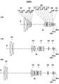
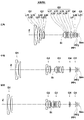
- FIG. 1 is a cross-sectional view showing a lens configuration of a zoom lens according to an embodiment of the present invention
- FIG. 2 is a cross-sectional view showing a movement locus of each lens group of the zoom lens.
- the configuration example shown in FIGS. 1 and 2 is common to the configuration of the zoom lens of Example 1 described later. 1 and 2, the left side is the object side, and the right side is the image side.
- This zoom lens has a first lens group G1 having a positive refractive power, a second lens group G2 having a negative refractive power, an aperture stop St, and a positive refractive power in order from the object side along the optical axis Z.
- the fifth lens group G5 is fixed, and at least the first lens group G1 and the fourth lens group G4 move.
- the aperture stop St shown in FIGS. 1 and 2 does not necessarily indicate the size or shape, but indicates the position on the optical axis Z.
- FIGS. 1 and 2 show an example in which the optical members PP1 and PP2 having the plane parallel plates are arranged between the fifth lens group G5 and the image plane Sim.
- the third lens group G3 has a cemented lens composed of a positive lens L31 and a negative lens L32 on the most object side, and has a cemented lens composed of a negative lens L36 and a positive lens L37 on the most image side.
- the fourth lens group G4 is composed of a negative lens L41 and a positive lens L42 in this order from the object side.
- the cemented lens By disposing the cemented lens at a distance from the most object side and the most image side of the third lens group G3, the effect of correcting the lateral chromatic aberration and the axial chromatic aberration of each cemented lens can be separated. It is possible to satisfactorily control the balance between upper chromatic aberration and lateral chromatic aberration.
- the aperture stop St at a position adjacent to the most object side cemented lens of the third lens group G3.
- the cemented lens closest to the object side has a correction effect on axial chromatic aberration
- the cemented lens closest to the image side has a correction effect on lateral chromatic aberration
- conditional expression (1) defines the ratio of the movement amount of the first lens group G1 and the movement amount of the fourth lens group G4, and if the lower limit of the conditional expression (1) is not reached, the first lens group G1, The zooming effect of the fourth lens group G4 is weakened, and it becomes difficult to ensure a sufficient zooming ratio while realizing miniaturization. On the contrary, if the upper limit of conditional expression (1) is exceeded, the correction effect on the field curvature of the fourth lens group G4 will be weakened, and it will be difficult to suppress the field curvature associated with zooming. If the following conditional expression (1-1), more preferably conditional expression (1-2) is satisfied, better characteristics can be obtained.
- D1 is the difference between the positions of the first lens group on the optical axis at the wide-angle end and the telephoto end
- D4 is the difference between the positions of the fourth lens group at the wide-angle end and the telephoto end on the optical axis.
- Conditional expression (2) defines the ratio of the focal length of the fifth lens group G5 to the focal length of the entire system at the telephoto end, and if the lower limit of conditional expression (2) is not reached, Excessive power makes it difficult to correct coma. On the other hand, if the upper limit of conditional expression (2) is exceeded, the power of the fifth lens group G5 becomes insufficient, and it becomes difficult to correct various aberrations at the telephoto end. If the following conditional expression (2-1), more preferably conditional expression (2-2) is satisfied, better characteristics can be obtained.
- f5 is the focal length of the fifth lens group
- ft is the focal length of the entire system at the telephoto end.
- the imaging position by moving the entire third lens group G3 or a part of the lens groups included in the third lens group G3 in a direction perpendicular to the optical axis.
- the imaging position by moving the cemented lens closest to the image side of the third lens group G3 in the direction perpendicular to the optical axis.
- Conditional expression (3) defines the ratio between the focal length of the most object side cemented lens and the focal length of the most image side cemented lens in the third lens group G3, and is lower than the lower limit of conditional expression (3).
- the sensitivity of the cemented lens closest to the object side in the third lens group G3 becomes high, and it becomes difficult to suppress performance degradation due to manufacturing errors.
- the upper limit of conditional expression (3) is exceeded, the balance of power between the most object side cemented lens and the most image side cemented lens in the third lens group G3 will be lost, making it difficult to correct spherical aberration. If the following conditional expression (3-1), more preferably conditional expression (3-2) is satisfied, better characteristics can be obtained.
- f3o is the focal length of the cemented lens closest to the object side in the third lens group
- f3i is the focal length of the cemented lens closest to the image side in the third lens group.
- the third lens group G3 includes, in order from the object side, an aperture stop St, a cemented lens of the positive lens L31 and the negative lens L32, a cemented lens of the negative lens L33 and the positive lens L34, a positive lens L35, and a negative lens L36. It is preferably composed of a cemented lens with the positive lens L37.
- the cemented lens composed of the positive lens L31 and the negative lens L32 corrects spherical aberration and axial chromatic aberration well in the entire variable magnification range
- the cemented lens composed of the negative lens L33 and the positive lens L34 has an axis in the entire variable magnification region.
- the positive lens L35 can correct spherical aberration well, and the cemented lens composed of the negative lens L36 and positive lens L37 can well correct lateral chromatic aberration in the entire zoom range. .
- Conditional expression (4) defines the ratio of the movement amount and focal length of the fourth lens group G4, and if the lower limit of the conditional expression (4) is not reached, the correction effect on the field curvature of the fourth lens group G4. Is insufficient, and it becomes difficult to obtain a good image in each zoom region. On the other hand, if the upper limit of conditional expression (4) is exceeded, the effect of correcting the curvature of field of the fourth lens group G4 becomes excessive, making it difficult to balance aberrations. If the following conditional expression (4-1) is satisfied, better characteristics can be obtained.
- Conditional expression (5) defines the ratio of the focal length of the fourth lens group G4 and the focal length of the fifth lens group G5. If the lower limit of the conditional expression (5) is not reached, the conditional expression (5) Excessive power makes it difficult to correct spherical aberration. On the other hand, if the upper limit of conditional expression (5) is exceeded, the power of the fifth lens group G5 becomes excessive and it becomes difficult to correct various aberrations. If the following conditional expression (5-1) is satisfied, better characteristics can be obtained.
- f4 is the focal length of the fourth lens group
- f5 is the focal length of the fifth lens group.
- Conditional expression (6) defines the ratio of the focal length of the fourth lens group G4 to the focal length of the entire system at the telephoto end, and if the lower limit of conditional expression (6) is not reached, Excessive power makes it difficult to correct spherical aberration. On the other hand, if the upper limit of conditional expression (6) is exceeded, the power of the fourth lens group G4 will be insufficient, and it will be difficult to correct off-axis aberrations. If the following conditional expression (6-1) is satisfied, better characteristics can be obtained.
- f4 is the focal length of the fourth lens group
- ft is the focal length of the entire system at the telephoto end.
- the fourth lens group G4 it is preferable to perform focusing by moving the fourth lens group G4 in the optical axis direction. Since the light beam diameter is small in the vicinity of the fourth lens group G4, a small and lightweight focus group can be realized by performing focusing by moving the fourth lens group G4 in the optical axis direction in this way.
- the second lens group G2 and the third lens group G3 move during zooming from the wide-angle end to the telephoto end. Thereby, a high zoom ratio can be realized while downsizing the optical system.
- the fifth lens group G5 is preferably composed of one positive lens L51 having a convex surface directed toward the image side. As a result, the cost can be reduced, and the ghost due to reflection from the imaging surface can be reduced.
- the material disposed closest to the object side specifically, glass is preferably used, or transparent ceramics may be used.
- the zoom lens when used in a harsh environment, it is preferable to provide a protective multilayer coating. Further, in addition to the protective coat, an antireflection coat for reducing ghost light during use may be applied.
- the optical members PP1 and PP2 are disposed between the lens system and the image plane Sim.
- the low-pass filter and various filters that cut a specific wavelength range are used as the lens.
- these various filters may be arranged between the lenses, or a coating having the same action as the various filters on the lens surface of any lens. May be applied.
- FIG. 1 is a sectional view showing the lens configuration of the zoom lens of Example 1.
- the optical members PP1 and PP2 are also shown, with the left side being the object side and the right side being the image side.
- the aperture stop St does not necessarily indicate the size or shape, but indicates the position on the optical axis Z.
- the zoom lens of Example 1 includes a first lens group G1 having a positive refractive power, a second lens group G2 having a negative refractive power, an aperture stop St, and a positive lens in order from the object side along the optical axis Z.
- the lens unit includes a third lens group G3 having a refractive power, a fourth lens group G4 having a negative refractive power, and a fifth lens group G5 having a positive refractive power.
- the first lens group G1 is composed of, in order from the object side, a cemented lens having a cemented surface composed of a negative lens L11 and a positive lens L12 and having a convex surface facing the object side, and a positive lens L13.
- the cemented lens including the negative lens L11 and the positive lens L12 has an effect of correcting axial chromatic aberration on the telephoto side
- the positive lens L13 has an effect of correcting field curvature at the telephoto end.
- the second lens group G2 includes, in order from the object side, a negative lens L24, a cemented lens including a negative lens L21, a negative lens L22, and a positive lens L23 having a cemented surface with a convex surface facing the object side, and a negative lens L24.
- the cemented lens composed of the negative lens L22 and the positive lens L23 has an effect of correcting lateral chromatic aberration at the wide angle end.
- the third lens group G3 includes, in order from the object side, a cemented lens including a positive lens L31 and a negative lens L32 and having a cemented surface with a convex surface facing the image side.
- the third lens group G3 includes a negative lens L33 and a positive lens L34 with the convex surface facing the object side.
- the cemented lens composed of the positive lens L31 and the negative lens L32 has an effect of correcting spherical aberration and axial chromatic aberration in the entire zoom range, and the cemented lens composed of the negative lens L33 and the positive lens L34 is axial on the entire zoom region. It has the effect of controlling the balance between chromatic aberration and chromatic aberration of magnification, the aspherical lens L35 has the effect of correcting spherical aberration, and the cemented lens composed of the negative lens L36 and the positive lens L37 corrects chromatic aberration of magnification in the entire zoom range.
- the fourth lens group G4 includes, in order from the object side, a negative lens L41 and an aspheric lens L42 having a positive refractive power.
- the negative lens L41 and the aspheric lens L42 have an effect of correcting field curvature in the entire zooming region.
- the fifth lens group G5 is composed of one aspherical lens L51 having a positive refractive power.
- the aspheric lens L51 has an effect of correcting distortion and curvature of field in the entire zoom region.
- the first lens group G1 moves to the object side
- the second lens group G2 moves to the image side
- the aperture stop St and the third lens group G3 are integrated with the object side.
- the fourth lens group G4 moves to the object side
- the fifth lens group G5 is fixed on the optical axis.
- focusing is performed by moving the fourth lens group G4 on the optical axis.
- cemented lens including the negative lens L36 and the positive lens L37 of the third lens group G3 is configured to be movable in a direction perpendicular to the optical axis for image stabilization.
- Table 1 shows basic lens data of the zoom lens of Example 1
- Table 2 shows data on specifications
- Table 3 shows data on the distance between moving surfaces
- Table 4 shows data on aspheric coefficients.
- the meaning of symbols in the table will be described by taking the example 1 as an example, but the same applies to the examples 2 to 6.
- Ri column indicates the radius of curvature of the i-th surface
- Di column indicates the surface spacing on the optical axis Z between the i-th surface and the i + 1-th surface.
- the column of ⁇ dj the Abbe number for the d-line (wavelength 587.6 nm) of the j-th optical element is also shown.
- the sign of the radius of curvature is positive when the surface shape is convex on the object side and negative when the surface shape is convex on the image side.
- the basic lens data includes the aperture stop St and the optical members PP1 and PP2.
- the phrase (aperture) is written together with the surface number.
- DD [i] is described in each column of the surface interval in which the interval changes at the time of zooming.
- the value in the bottom column of Di is the distance between the image side surface of the optical member PP and the image surface Sim.
- the surface number of the aspheric surface is marked with *, and the paraxial radius of curvature is shown as the radius of curvature of the aspheric surface.
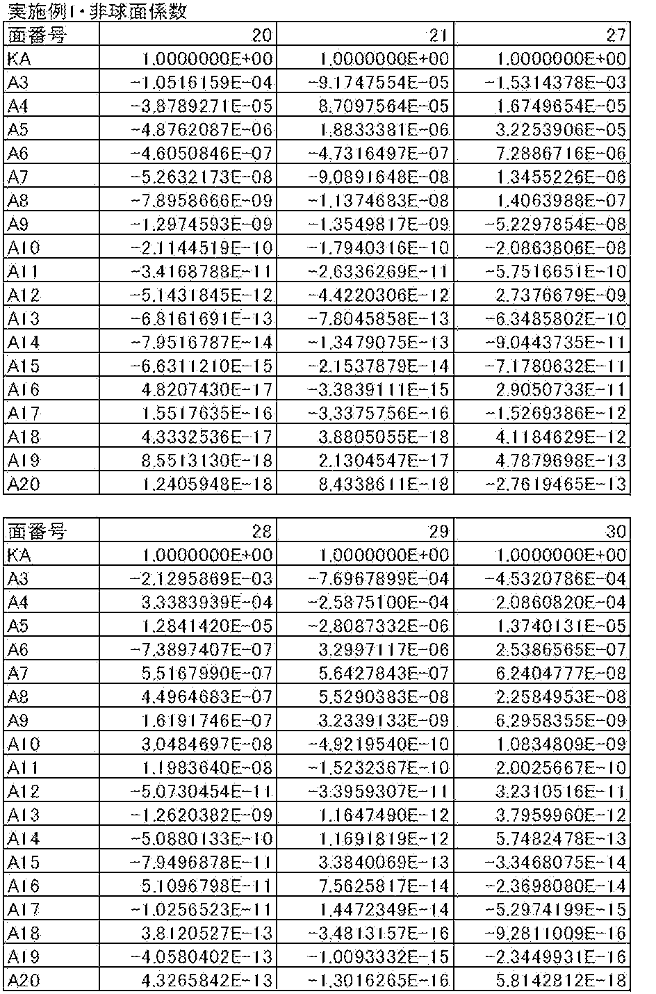
- the data relating to the aspheric coefficients in Table 4 shows the surface numbers Si of the aspheric surfaces and the aspheric coefficients related to these aspheric surfaces.
- Zd C ⁇ h 2 / ⁇ 1+ (1 ⁇ KA ⁇ C 2 ⁇ h 2 ) 1/2 ⁇ + ⁇ Am ⁇ h m (B)
- Zd Depth of aspheric surface (length of a perpendicular line drawn from a point on the aspherical surface at height h to a plane perpendicular to the optical axis where the aspherical vertex contacts)
- h Height (distance from the optical axis)
- C Reciprocal KA of paraxial radius of curvature
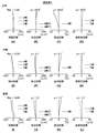
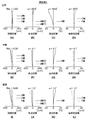
- FIGS. 8A to 8L show aberration diagrams of the zoom lens of Example 1.
- FIG. 8A to 8D show wide-angle spherical aberration, astigmatism, distortion, and lateral chromatic aberration, respectively.
- FIGS. 8E to 8H show intermediate spherical aberration, astigmatism, and distortion, respectively.
- FIGS. 8 (I) to 8 (L) show telephoto spherical aberration, astigmatism, distortion, and lateral chromatic aberration, respectively.
- Each aberration diagram representing spherical aberration, astigmatism, and distortion shows aberrations with the d-line (wavelength 587.6 nm) as the reference wavelength.
- the spherical aberration diagram aberrations for the d-line (wavelength 587.6 nm), the C-line (wavelength 656.3 nm), and the F-line (wavelength 486.1 nm) are shown by a solid line, a long broken line, a short broken line, and a dotted line, respectively.
- the sagittal and tangential aberrations are indicated by a solid line and a broken line, respectively.
- FIG. 3 is a cross-sectional view showing the lens configuration of the zoom lens of Example 2.
- the zoom lens of Example 2 has the same shape as the zoom lens of Example 1.
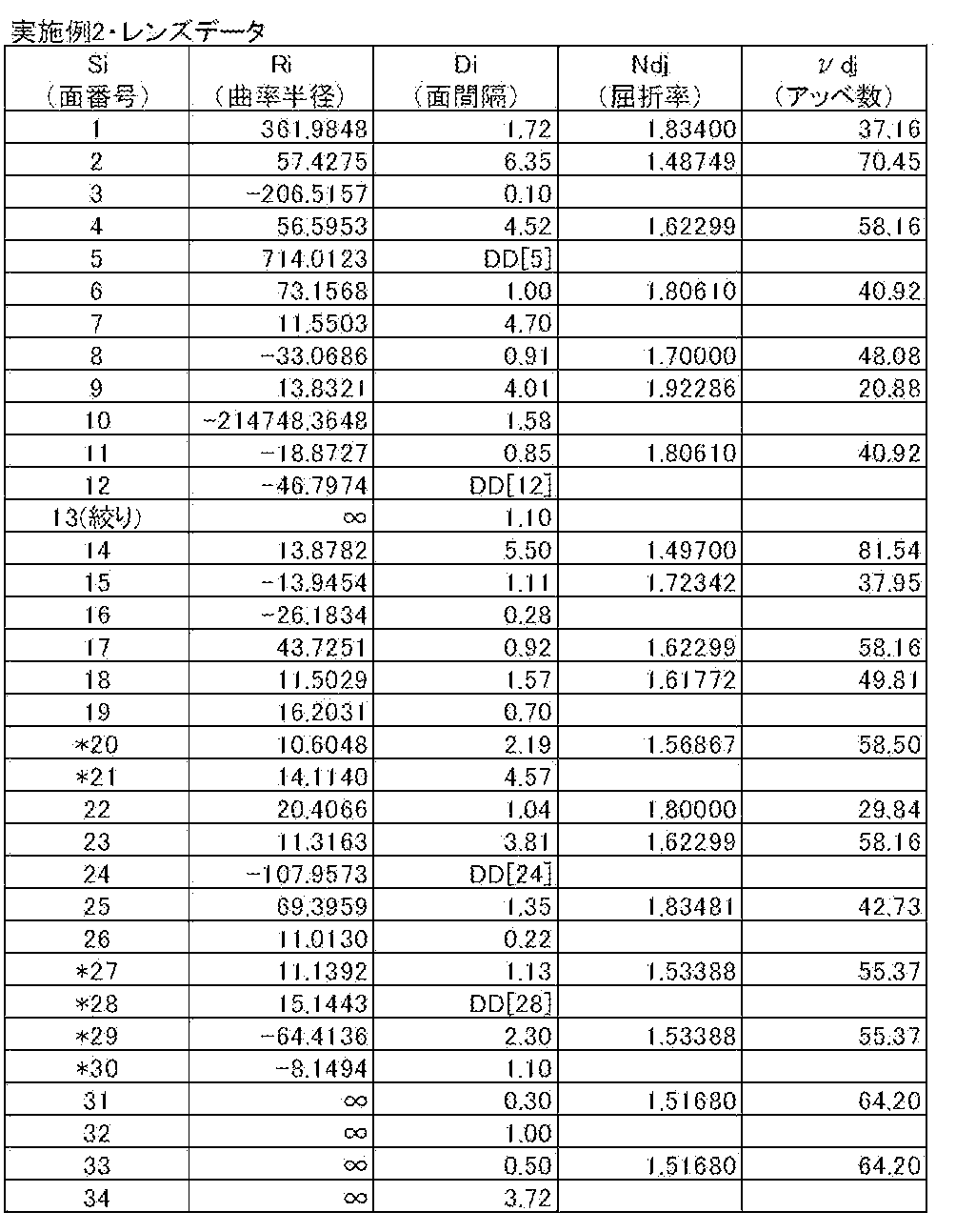
- Table 5 shows basic lens data of the zoom lens of Example 2
- Table 6 shows data on specifications
- Table 7 shows data on the distance between moving surfaces
- Table 8 shows data on aspheric coefficients
- FIG. Are shown in FIGS. 9 (A) to 9 (L).
- FIG. 4 is a sectional view showing the lens configuration of the zoom lens of Example 3. As shown in FIG.
- the zoom lens of Example 3 has the same shape as the zoom lens of Example 1.
- Table 9 shows basic lens data of the zoom lens of Example 3
- Table 10 shows data on specifications
- Table 11 shows data on distances of moving surfaces
- Table 12 shows data on aspheric coefficients
- FIG. Are shown in FIGS. 10 (A) to 10 (L).
- FIG. 5 is a sectional view showing the lens configuration of the zoom lens of Example 4. As shown in FIG.
- the zoom lens of Example 4 has the same shape as the zoom lens of Example 1.
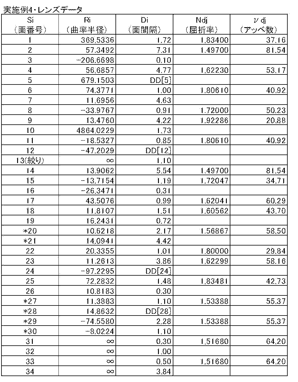
- Table 13 shows basic lens data of the zoom lens of Example 4
- Table 14 shows data on specifications
- Table 15 shows data on the distance between moving surfaces
- Table 16 shows data on aspheric coefficients
- FIG. Are shown in FIGS. 11 (A) to 11 (L).
- FIG. 6 is a cross-sectional view showing the lens configuration of the zoom lens of Example 5.
- the zoom lens of Example 5 has the same shape as the zoom lens of Example 1.
- Table 17 shows basic lens data of the zoom lens of Example 5
- Table 18 shows data on specifications
- Table 19 shows data on the distance between moving surfaces
- Table 20 shows data on aspheric coefficients
- FIG. Are shown in FIGS. 12 (A) to (L).
- FIG. 7 is a sectional view showing the lens configuration of the zoom lens of Example 6.
- the zoom lens of Example 6 has the same shape as the zoom lens of Example 1.
- Table 21 shows basic lens data of the zoom lens of Example 6
- Table 22 shows data on specifications
- Table 23 shows data on the distance between moving surfaces
- Table 24 shows data on aspheric coefficients
- FIG. Are shown in FIGS. 13A to 13L.
- Table 25 shows values corresponding to the conditional expressions (1) to (6) of the zoom lenses of Examples 1 to 6.
- the d-line is used as a reference wavelength, and the values shown in Table 25 below are at this reference wavelength.
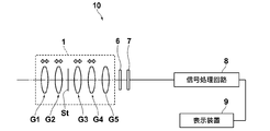
- FIG. 14 is a schematic configuration diagram of an imaging apparatus using the zoom lens according to the embodiment of the present invention as an example of the imaging apparatus according to the embodiment of the present invention.
- FIG. 14 schematically shows each lens group.
- the imaging apparatus include a video camera and an electronic still camera that use a solid-state imaging device such as a CCD or CMOS as a recording medium.
- the 14 includes a zoom lens 1, a filter 6 having a function such as a low-pass filter disposed on the image side of the zoom lens 1, an image sensor 7 disposed on the image side of the filter 6, and a signal. And a processing circuit 8.
- the image sensor 7 converts an optical image formed by the zoom lens 1 into an electrical signal.
- a CCD Charge-Coupled Device
- CMOS Complementary Metal-Oxide Semiconductor
- the image sensor 7 is arranged so that its image plane coincides with the image plane of the zoom lens 1.
- An image picked up by the zoom lens 1 is formed on the image pickup surface of the image pickup device 7, an output signal from the image pickup device 7 relating to the image is subjected to arithmetic processing by the signal processing circuit 8, and the image is displayed on the display device 9.
- the present invention has been described with reference to the embodiments and examples. However, the present invention is not limited to the above-described embodiments and examples, and various modifications can be made.
- the values of the radius of curvature, the surface spacing, the refractive index, the Abbe number, etc. of each lens component are not limited to the values shown in the above numerical examples, but can take other values.
Landscapes
- Physics & Mathematics (AREA)
- General Physics & Mathematics (AREA)
- Optics & Photonics (AREA)
- Nonlinear Science (AREA)
- Lenses (AREA)
- Adjustment Of Camera Lenses (AREA)
Description
本発明は、ズームレンズおよび撮像装置に関し、より詳しくは、デジタルカメラ、放送用カメラ、監視用カメラ、映画撮影用カメラ等の電子カメラに用いられるズームレンズおよび該ズームレンズを備えた撮像装置に関するものである。
CCD(Charge Coupled Device)やCMOS(Complementary Metal Oxide Semiconductor)等の撮像素子を記録媒体とするビデオカメラや電子スチルカメラ等の撮像装置に用いられるズームレンズでは、高変倍比化への要求が高まっている。高変倍比を実現するズームレンズのタイプとして、物体側より順に、正、負、正、負、正の群配置を有する5群方式のズームレンズが知られている(例えば特許文献1~4)。
特許文献1~3では、変倍比が10~14.3程度のズームレンズが開示されている。さらに特許文献4では、変倍比が28.3程度のズームレンズが開示されている。
しかしながら、さらなる高変倍比のズームレンズを実現しようとすると、光学系が大型化しやすく、全変倍領域において諸収差を良好に補正することが困難になるという問題がある。
本発明は、上記事情に鑑みてなされたものであり、高変倍比でありながら、小型で、全変倍領域において諸収差が良好に補正されたズームレンズおよび該ズームレンズを備えた撮像装置を提供することを目的とするものである。
本発明のズームレンズは、物体側から順に、正の屈折力を有する第1レンズ群、負の屈折力を有する第2レンズ群、正の屈折力を有する第3レンズ群、負の屈折力を有する第4レンズ群、正の屈折力を有する第5レンズ群からなり、第3レンズ群は、最も物体側と最も像側に接合レンズを有し、第4レンズ群は、物体側から順に負レンズ、正レンズからなり、広角端から望遠端への変倍に際して、各レンズ群の間隔が変化し、第5レンズ群は固定され、少なくとも第1レンズ群および第4レンズ群は移動することを特徴とする。
本発明のズームレンズにおいては、第3レンズ群の最も物体側の接合レンズに隣接する位置に開口絞りを配置することが好ましい。
また、第1レンズ群および第4レンズ群は、望遠端において広角端よりも物体側に位置し、下記条件式を満足することが好ましい。
2.0<|D1|/|D4|<8.0 …(1)
ただし、D1:第1レンズ群の広角端と望遠端における光軸上の位置の差、D4:第4レンズ群の広角端と望遠端における光軸上の位置の差とする。
ただし、D1:第1レンズ群の広角端と望遠端における光軸上の位置の差、D4:第4レンズ群の広角端と望遠端における光軸上の位置の差とする。
また、下記条件式を満足することが好ましい。
0.05<|f5|/ft<0.20 …(2)
ただし、f5:第5レンズ群の焦点距離、ft:望遠端における全系の焦点距離とする。
ただし、f5:第5レンズ群の焦点距離、ft:望遠端における全系の焦点距離とする。
また、第3レンズ群全体あるいは第3レンズ群に含まれる一部のレンズ群を光軸と垂直な方向に移動させて結像位置を変化させることが好ましい。
また、第3レンズ群の最も像側の接合レンズを光軸と垂直な方向に移動させて結像位置を変化させることが好ましい。
また、下記条件式を満足することが好ましい。
0.4<f3o/f3i<0.9 …(3)
ただし、f3o:第3レンズ群の最も物体側の接合レンズの焦点距離、f3i:第3レンズ群の最も像側の接合レンズの焦点距離とする。
ただし、f3o:第3レンズ群の最も物体側の接合レンズの焦点距離、f3i:第3レンズ群の最も像側の接合レンズの焦点距離とする。
また、第3レンズ群は、物体側から順に、開口絞り、正レンズと負レンズとの接合レンズ、負レンズと正レンズとの接合レンズ、正レンズ、負レンズと正レンズとの接合レンズからなることが好ましい。
また、下記条件式を満足することが好ましい。
0.30<|D4|/|f4|<1.00 …(4)
ただし、D4:第4レンズ群の広角端と望遠端における光軸上の位置の差、f4:第4レンズ群の焦点距離とする。
ただし、D4:第4レンズ群の広角端と望遠端における光軸上の位置の差、f4:第4レンズ群の焦点距離とする。
また、下記条件式を満足することが好ましい。
0.80<|f4|/|f5|<1.40 …(5)
ただし、f4:第4レンズ群の焦点距離、f5:第5レンズ群の焦点距離とする。
ただし、f4:第4レンズ群の焦点距離、f5:第5レンズ群の焦点距離とする。
また、下記条件式を満足することが好ましい。
0.05<|f4|/ft<0.18 …(6)
ただし、f4:第4レンズ群の焦点距離、ft:望遠端における全系の焦点距離とする。
ただし、f4:第4レンズ群の焦点距離、ft:望遠端における全系の焦点距離とする。
また、第4レンズ群を光軸方向に移動させることによりフォーカシングを行うことが好ましい。
また、広角端から望遠端への変倍に際して、第2レンズ群および第3レンズ群は移動することが好ましい。
また、第5レンズ群は、像側に凸面を向けた1枚の正レンズからなることが好ましい。
また、第1レンズ群および第4レンズ群は、望遠端において広角端よりも物体側に位置し、下記条件式を満足することが好ましい。
4.0<|D1|/|D4|<7.5 …(1-1)
また、第1レンズ群および第4レンズ群は、望遠端において広角端よりも物体側に位置し、下記条件式を満足することが好ましい。
また、第1レンズ群および第4レンズ群は、望遠端において広角端よりも物体側に位置し、下記条件式を満足することが好ましい。
4.5<|D1|/|D4|<7.0 …(1-2)
また、下記条件式を満足することが好ましい。
また、下記条件式を満足することが好ましい。
0.07<|f5|/ft<0.11 …(2-1)
また、下記条件式を満足することが好ましい。
また、下記条件式を満足することが好ましい。
0.09<|f5|/ft<0.10 …(2-2)
また、下記条件式を満足することが好ましい。
また、下記条件式を満足することが好ましい。
0.5<f3o/f3i<0.8 …(3-1)
また、下記条件式を満足することが好ましい。
また、下記条件式を満足することが好ましい。
0.6<f3o/f3i<0.7 …(3-2)
また、下記条件式を満足することが好ましい。
また、下記条件式を満足することが好ましい。
0.50<|D4|/|f4|<0.80 …(4-1)
また、下記条件式を満足することが好ましい。
また、下記条件式を満足することが好ましい。
0.90<|f4|/|f5|<1.18 …(5-1)
また、下記条件式を満足することが好ましい。
また、下記条件式を満足することが好ましい。
0.07<|f4|/ft<0.12 …(6-1)
本発明の撮像装置は、上記記載の本発明のズームレンズを備えたことを特徴とするものである。
本発明の撮像装置は、上記記載の本発明のズームレンズを備えたことを特徴とするものである。
本発明のズームレンズは、物体側から順に、正の屈折力を有する第1レンズ群、負の屈折力を有する第2レンズ群、正の屈折力を有する第3レンズ群、負の屈折力を有する第4レンズ群、正の屈折力を有する第5レンズ群からなり、第3レンズ群は、最も物体側と最も像側に接合レンズを有し、第4レンズ群は、物体側から順に負レンズ、正レンズからなり、広角端から望遠端への変倍に際して、各レンズ群の間隔が変化し、第5レンズ群は固定され、少なくとも第1レンズ群および第4レンズ群は移動するものとしたので、高変倍比でありながら、小型で、全変倍領域において諸収差が良好に補正されたズームレンズとすることが可能となる。
また、本発明の撮像装置は、本発明のズームレンズを備えているため、高変倍比で、高画質の映像を得ることができるとともに、装置の小型化も可能となる。
以下、本発明の実施形態について図面を参照して詳細に説明する。図1は本発明の一実施形態にかかるズームレンズのレンズ構成を示す断面図、図2は上記ズームレンズの各レンズ群の移動軌跡を示す断面図である。図1、2に示す構成例は、後述の実施例1のズームレンズの構成と共通である。図1、2においては、左側が物体側、右側が像側である。
このズームレンズは、光軸Zに沿って、物体側から順に、正の屈折力を有する第1レンズ群G1、負の屈折力を有する第2レンズ群G2、開口絞りSt、正の屈折力を有する第3レンズ群G3、負の屈折力を有する第4レンズ群G4、正の屈折力を有する第5レンズ群G5からなり、広角端から望遠端への変倍に際して、各レンズ群の間隔が変化し、第5レンズ群G5は固定され、少なくとも第1レンズ群G1および第4レンズ群G4が移動するものである。ここで、図1、2に示す開口絞りStは必ずしも大きさや形状を表すものではなく、光軸Z上の位置を示すものである。
このズームレンズを撮像装置に適用する際には、レンズを装着するカメラ側の構成に応じて、光学系と像面Simの間にカバーガラス、プリズム、赤外線カットフィルタやローパスフィルタなどの各種フィルタを配置することが好ましいため、図1、2では、これらを想定した平行平面板状の光学部材PP1、PP2を第5レンズ群G5と像面Simとの間に配置した例を示している。
第3レンズ群G3は、最も物体側において正レンズL31と負レンズL32とからなる接合レンズを有し、最も像側において負レンズL36と正レンズL37とからなる接合レンズを有する。
第4レンズ群G4は、物体側から順に、負レンズL41、正レンズL42からなる。
第3レンズ群G3の最も物体側と最も像側に間隔を離して接合レンズを配置することにより、それぞれの接合レンズの倍率色収差と軸上色収差への補正の効果を分離することができ、軸上色収差と倍率色収差のバランスを良好にコントロールすることが可能になる。
また、第4レンズ群G4を上記の様に構成することにより、像面湾曲の良好な補正が実現できる。
本実施形態のズームレンズにおいては、第3レンズ群G3の最も物体側の接合レンズに隣接する位置に開口絞りStを配置することが好ましい。これにより、最も物体側の接合レンズが軸上色収差の補正効果を有し、最も像側の接合レンズが倍率色収差の補正効果を有し、全変倍領域での軸上色収差と倍率色収差のバランスのコントロールが容易になる。
また、第1レンズ群G1および第4レンズ群G4は、望遠端において広角端よりも物体側に位置し、下記条件式(1)を満足することが好ましい。この条件式(1)は、第1レンズ群G1の移動量と第4レンズ群G4の移動量の比率を規定しており、条件式(1)の下限を下回ると、第1レンズ群G1、第4レンズ群G4の変倍効果が弱まり、小型化を実現しながら十分な変倍比を確保することが困難になる。逆に、条件式(1)の上限を上回ると、第4レンズ群G4の像面湾曲に対する補正効果が弱まり、変倍に伴う像面湾曲を抑えることが困難になる。なお、下記条件式(1-1)、より好ましくは条件式(1-2)を満足するものとすれば、より良好な特性とすることができる。
2.0<|D1|/|D4|<8.0 …(1)
4.0<|D1|/|D4|<7.5 …(1-1)
4.5<|D1|/|D4|<7.0 …(1-2)
ただし、D1:第1レンズ群の広角端と望遠端における光軸上の位置の差、D4:第4レンズ群の広角端と望遠端における光軸上の位置の差とする。
4.0<|D1|/|D4|<7.5 …(1-1)
4.5<|D1|/|D4|<7.0 …(1-2)
ただし、D1:第1レンズ群の広角端と望遠端における光軸上の位置の差、D4:第4レンズ群の広角端と望遠端における光軸上の位置の差とする。
また、下記条件式(2)を満足することが好ましい。この条件式(2)は、第5レンズ群G5の焦点距離と望遠端における全系の焦点距離の比を規定しており、条件式(2)の下限を下回ると、第5レンズ群G5のパワーが過剰となりコマ収差の補正が困難になる。逆に、条件式(2)の上限を上回ると、第5レンズ群G5のパワーが不足し、望遠端における諸収差の補正が困難になる。なお、下記条件式(2-1)、より好ましくは条件式(2-2)を満足するものとすれば、より良好な特性とすることができる。
0.05<|f5|/ft<0.20 …(2)
0.07<|f5|/ft<0.11 …(2-1)
0.09<|f5|/ft<0.10 …(2-2)
ただし、f5:第5レンズ群の焦点距離、ft:望遠端における全系の焦点距離とする。
0.07<|f5|/ft<0.11 …(2-1)
0.09<|f5|/ft<0.10 …(2-2)
ただし、f5:第5レンズ群の焦点距離、ft:望遠端における全系の焦点距離とする。
また、第3レンズ群G3全体あるいは第3レンズ群G3に含まれる一部のレンズ群を光軸と垂直な方向に移動させて結像位置を変化させることが好ましい。これにより、全変倍領域において性能劣化の少ない手ぶれ補正機構が実現できる。
また、第3レンズ群G3の最も像側の接合レンズを光軸と垂直な方向に移動させて結像位置を変化させることが好ましい。これにより、移動させるレンズの重量を抑えながら、全変倍領域において性能劣化の少ない手ぶれ補正機構が実現できる。
また、下記条件式(3)を満足することが好ましい。この条件式(3)は、第3レンズ群G3の最も物体側の接合レンズの焦点距離と最も像側の接合レンズの焦点距離の比率を規定しており、条件式(3)の下限を下回ると、第3レンズ群G3の最も物体側の接合レンズの感度が高くなり、製造誤差による性能劣化を抑えることが困難になる。逆に、条件式(3)の上限を上回ると、第3レンズ群G3の最も物体側の接合レンズと最も像側の接合レンズのパワーのバランスが崩れ球面収差の補正が困難になる。なお、下記条件式(3-1)、より好ましくは条件式(3-2)を満足するものとすれば、より良好な特性とすることができる。
0.4<f3o/f3i<0.9 …(3)
0.5<f3o/f3i<0.8 …(3-1)
0.6<f3o/f3i<0.7 …(3-2)
ただし、f3o:第3レンズ群の最も物体側の接合レンズの焦点距離、f3i:第3レンズ群の最も像側の接合レンズの焦点距離とする。
0.5<f3o/f3i<0.8 …(3-1)
0.6<f3o/f3i<0.7 …(3-2)
ただし、f3o:第3レンズ群の最も物体側の接合レンズの焦点距離、f3i:第3レンズ群の最も像側の接合レンズの焦点距離とする。
また、第3レンズ群G3は、物体側から順に、開口絞りSt、正レンズL31と負レンズL32との接合レンズ、負レンズL33と正レンズL34との接合レンズ、正レンズL35、負レンズL36と正レンズL37との接合レンズからなることが好ましい。これにより、正レンズL31と負レンズL32からなる接合レンズが全変倍域における球面収差と軸上色収差を良好に補正し、負レンズL33と正レンズL34からなる接合レンズが全変倍域における軸上色収差と倍率色収差のバランスをコントロールし、正レンズL35が球面収差を良好に補正し、負レンズL36と正レンズL37からなる接合レンズが全変倍域における倍率色収差を良好に補正することができる。
また、下記条件式(4)を満足することが好ましい。この条件式(4)は、第4レンズ群G4の移動量と焦点距離の比率を規定しており、条件式(4)の下限を下回ると、第4レンズ群G4の像面湾曲に対する補正効果が不足し各変倍領域で良好な像を得ることが困難になる。逆に、条件式(4)の上限を上回ると、第4レンズ群G4の像面湾曲に対する補正効果が過剰となり収差のバランスを取ることが困難になる。なお、下記条件式(4-1)を満足するものとすれば、より良好な特性とすることができる。
0.30<|D4|/|f4|<1.00 …(4)
0.50<|D4|/|f4|<0.80 …(4-1)
ただし、D4:第4レンズ群の広角端と望遠端における光軸上の位置の差、f4:第4レンズ群の焦点距離とする。
0.50<|D4|/|f4|<0.80 …(4-1)
ただし、D4:第4レンズ群の広角端と望遠端における光軸上の位置の差、f4:第4レンズ群の焦点距離とする。
また、下記条件式(5)を満足することが好ましい。この条件式(5)は、第4レンズ群G4の焦点距離と第5レンズ群G5の焦点距離の比を規定しており、条件式(5)の下限を下回ると、第4レンズ群G4のパワーが過剰となり球面収差の補正が困難になる。逆に、条件式(5)の上限を上回ると、第5レンズ群G5のパワーが過剰となり諸収差の補正が困難になる。なお、下記条件式(5-1)を満足するものとすれば、より良好な特性とすることができる。
0.80<|f4|/|f5|<1.40 …(5)
0.90<|f4|/|f5|<1.18 …(5-1)
ただし、f4:第4レンズ群の焦点距離、f5:第5レンズ群の焦点距離とする。
0.90<|f4|/|f5|<1.18 …(5-1)
ただし、f4:第4レンズ群の焦点距離、f5:第5レンズ群の焦点距離とする。
また、下記条件式(6)を満足することが好ましい。この条件式(6)は、第4レンズ群G4の焦点距離と望遠端における全系の焦点距離の比を規定しており、条件式(6)の下限を下回ると、第4レンズ群G4のパワーが過剰となり球面収差の補正が困難になる。逆に、条件式(6)の上限を上回ると、第4レンズ群G4のパワーが不足し軸外での収差の補正が困難になる。なお、下記条件式(6-1)を満足するものとすれば、より良好な特性とすることができる。
0.05<|f4|/ft<0.18 …(6)
0.07<|f4|/ft<0.12 …(6-1)
ただし、f4:第4レンズ群の焦点距離、ft:望遠端における全系の焦点距離とする。
0.07<|f4|/ft<0.12 …(6-1)
ただし、f4:第4レンズ群の焦点距離、ft:望遠端における全系の焦点距離とする。
また、第4レンズ群G4を光軸方向に移動させることによりフォーカシングを行うことが好ましい。第4レンズ群G4近傍においては光束径が小さくなるため、このように第4レンズ群G4を光軸方向に移動させてフォーカシングを行うことで、小型で軽量なフォーカス群が実現できる。
また、広角端から望遠端への変倍に際して、第2レンズ群G2および第3レンズ群G3は移動することが好ましい。これにより、光学系を小型化しながら高い変倍比を実現できる。
また、第5レンズ群G5は、像側に凸面を向けた1枚の正レンズL51からなることが好ましい。これにより、コストを抑えられ、また結像面からの反射によるゴーストの低減が実現できる。
本ズームレンズにおいて、最も物体側に配置される材料としては、具体的にはガラスを用いることが好ましく、あるいは透明なセラミックスを用いてもよい。
また、本ズームレンズが厳しい環境において使用される場合には、保護用の多層膜コートが施されることが好ましい。さらに、保護用コート以外にも、使用時のゴースト光低減等のための反射防止コートを施すようにしてもよい。
また、図1に示す例では、レンズ系と像面Simとの間に光学部材PP1、PP2を配置した例を示したが、ローパスフィルタや特定の波長域をカットするような各種フィルタ等をレンズ系と像面Simとの間に配置する代わりに、各レンズの間にこれらの各種フィルタを配置してもよく、あるいは、いずれかのレンズのレンズ面に、各種フィルタと同様の作用を有するコートを施してもよい。
次に、本発明のズームレンズの数値実施例について説明する。
まず、実施例1のズームレンズについて説明する。実施例1のズームレンズのレンズ構成を示す断面図を図1に示す。なお、図1および後述の実施例2~6に対応した図3~7においては、光学部材PP1、PP2も合わせて示しており、左側が物体側、右側が像側であり、図示されている開口絞りStは必ずしも大きさや形状を表すものではなく、光軸Z上の位置を示すものである。
実施例1のズームレンズは、光軸Zに沿って、物体側から順に、正の屈折力を有する第1レンズ群G1、負の屈折力を有する第2レンズ群G2、開口絞りSt、正の屈折力を有する第3レンズ群G3、負の屈折力を有する第4レンズ群G4、正の屈折力を有する第5レンズ群G5からなる。
第1レンズ群G1は、物体側から順に、負レンズL11と正レンズL12からなり物体側に凸面を向けた接合面を有する接合レンズ、正レンズL13で構成される。負レンズL11と正レンズL12からなる接合レンズは望遠側における軸上色収差を補正する効果を有し、正レンズL13は望遠端における像面湾曲を補正する効果を有する。
第2レンズ群G2は、物体側から順に、負レンズL21、負レンズL22と正レンズL23からなり物体側に凸面を向けた接合面を有する接合レンズ、負レンズL24で構成される。負レンズL22と正レンズL23からなる接合レンズは広角端における倍率色収差を補正する効果を有する。
第3レンズ群G3は、物体側から順に、正レンズL31と負レンズL32からなり像側に凸面を向けた接合面を有する接合レンズ、負レンズL33と正レンズL34からなり物体側に凸面を向けた接合面を有する接合レンズ、正の屈折力を有する非球面レンズL35、負レンズL36と正レンズL37からなり物体側に凸面を向けた接合面を有する接合レンズで構成される。正レンズL31と負レンズL32からなる接合レンズは全変倍域における球面収差と軸上色収差を補正する効果を有し、負レンズL33と正レンズL34からなる接合レンズは全変倍域における軸上色収差と倍率色収差のバランスをコントロールする効果を有し、非球面レンズL35は球面収差を補正する効果を有し、負レンズL36と正レンズL37からなる接合レンズは全変倍域における倍率色収差を補正する効果を有する。
第4レンズ群G4は、物体側から順に、負レンズL41、正の屈折力を有する非球面レンズL42で構成される。負レンズL41および非球面レンズL42は全変倍領域において像面湾曲を補正する効果を有する。
第5レンズ群G5は、正の屈折力を有する非球面レンズL51の1枚で構成される。この非球面レンズL51は全変倍領域において歪曲収差、像面湾曲を補正する効果を有する。
広角端から望遠端への変倍に際して、第1レンズ群G1は物体側に移動し、第2レンズ群G2は像側に移動し、開口絞りStと第3レンズ群G3は一体的に物体側に移動し、第4レンズ群G4は物体側に移動し、第5レンズ群G5は光軸上に固定される。
また、第4レンズ群G4を光軸上に移動させることによりフォーカスを行う。
また、第3レンズ群G3の負レンズL36と正レンズL37からなる接合レンズは、防振のために光軸上と垂直な方向へ移動可能となるように構成される。
実施例1のズームレンズの基本レンズデータを表1に、諸元に関するデータを表2に、移動面の間隔に関するデータを表3に、非球面係数に関するデータを表4に示す。以下では、表中の記号の意味について、実施例1のものを例にとり説明するが、実施例2~6についても基本的に同様である。
表1のレンズデータにおいて、Siの欄には最も物体側の構成要素の面を1番目として像側に向かうに従い順次増加するi番目(i=1、2、3、…)の面番号を示し、Riの欄にはi番目の面の曲率半径を示し、Diの欄にはi番目の面とi+1番目の面との光軸Z上の面間隔を示す。また、Ndjの欄には最も物体側の光学要素を1番目として像側に向かうに従い順次増加するj番目(j=1、2、3、…)の光学要素のd線(波長587.6nm)に対する屈折率を示し、νdjの欄には同じくj番目の光学要素のd線(波長587.6nm)に対するアッベ数を示す。
なお、曲率半径の符号は、面形状が物体側に凸の場合を正、像側に凸の場合を負としている。基本レンズデータには、開口絞りSt、光学部材PP1、PP2も含めて示している。開口絞りStに相当する面の面番号の欄には面番号とともに(絞り)という語句を記載している。また、表1のレンズデータにおいて、変倍時に間隔が変化する面間隔の欄にはそれぞれDD[i]と記載している。また、Diの最下欄の値は、光学部材PPの像側の面と像面Simとの間隔である。
表2の諸元に関するデータに、広角・中間・望遠の各々の、ズーム倍率、焦点距離f´、F値FNo.および全画角2ωの値を示す。
基本レンズデータ、諸元に関するデータ、および移動面の間隔に関するデータにおいて、角度の単位としては度を用い、長さの単位としてはmmを用いているが、光学系は比例拡大又は比例縮小しても使用可能なため他の適当な単位を用いることもできる。
表1のレンズデータでは、非球面の面番号に*印を付しており、非球面の曲率半径として近軸の曲率半径の数値を示している。表4の非球面係数に関するデータには、非球面の面番号Siと、これら非球面に関する非球面係数を示す。非球面係数は、以下の式(A)で表される非球面式における各係数KA、Am(m=3、4、5、…20)の値である。
Zd=C・h2/{1+(1-KA・C2・h2)1/2}+ΣAm・hm …(B)
ただし、
Zd:非球面深さ(高さhの非球面上の点から、非球面頂点が接する光軸に垂直な平面に下ろした垂線の長さ)
h:高さ(光軸からの距離)
C:近軸曲率半径の逆数
KA、Am:非球面係数(m=3、4、5、…20)



ただし、
Zd:非球面深さ(高さhの非球面上の点から、非球面頂点が接する光軸に垂直な平面に下ろした垂線の長さ)
h:高さ(光軸からの距離)
C:近軸曲率半径の逆数
KA、Am:非球面係数(m=3、4、5、…20)
実施例1のズームレンズの各収差図を図8(A)~(L)に示す。図8(A)~(D)はそれぞれ広角の球面収差、非点収差、歪曲収差、倍率色収差を示し、図8(E)~(H)はそれぞれ中間の球面収差、非点収差、歪曲収差、倍率色収差を示し、図8(I)~(L)はそれぞれ望遠の球面収差、非点収差、歪曲収差、倍率色収差を示す。
球面収差、非点収差、歪曲収差を表す各収差図には、d線(波長587.6nm)を基準波長とした収差を示す。球面収差図にはd線(波長587.6nm)、C線(波長656.3nm)、F線(波長486.1nm)についての収差をそれぞれ実線、長破線、短破線、点線で示す。非点収差図にはサジタル方向、タンジェンシャル方向の収差をそれぞれ実線と破線で示す。倍率色収差図にはC線(波長656.3nm)、F線(波長486.1nm)についての収差をそれぞれ長破線、短破線、点線で示す。なお、球面収差図のFno.はF値、その他の収差図のωは半画角を意味する。
次に、実施例2のズームレンズについて説明する。実施例2のズームレンズのレンズ構成を示す断面図を図3に示す。
実施例2のズームレンズは、実施例1のズームレンズと同様の形状である。
また、実施例2のズームレンズの基本レンズデータを表5に、諸元に関するデータを表6に、移動面の間隔に関するデータを表7に、非球面係数に関するデータを表8に、各収差図を図9(A)~(L)に示す。


次に、実施例3のズームレンズについて説明する。実施例3のズームレンズのレンズ構成を示す断面図を図4に示す。
実施例3のズームレンズも、実施例1のズームレンズと同様の形状である。
また、実施例3のズームレンズの基本レンズデータを表9に、諸元に関するデータを表10に、移動面の間隔に関するデータを表11に、非球面係数に関するデータを表12に、各収差図を図10(A)~(L)に示す。




次に、実施例4のズームレンズについて説明する。実施例4のズームレンズのレンズ構成を示す断面図を図5に示す。
実施例4のズームレンズも、実施例1のズームレンズと同様の形状である。
また、実施例4のズームレンズの基本レンズデータを表13に、諸元に関するデータを表14に、移動面の間隔に関するデータを表15に、非球面係数に関するデータを表16に、各収差図を図11(A)~(L)に示す。


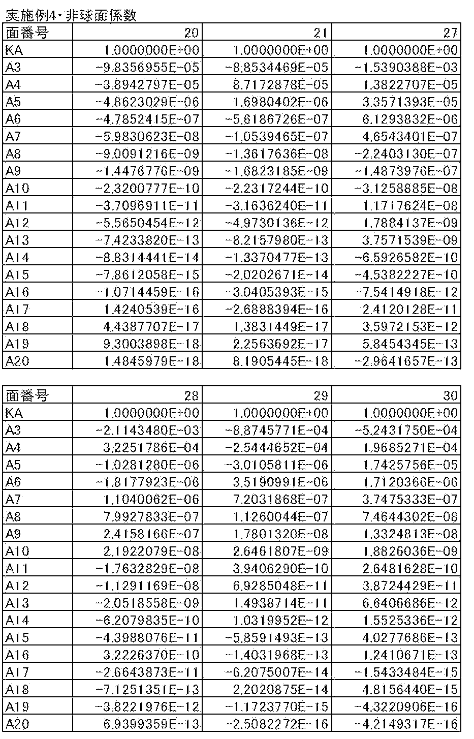
次に、実施例5のズームレンズについて説明する。実施例5のズームレンズのレンズ構成を示す断面図を図6に示す。
実施例5のズームレンズも、実施例1のズームレンズと同様の形状である。
また、実施例5のズームレンズの基本レンズデータを表17に、諸元に関するデータを表18に、移動面の間隔に関するデータを表19に、非球面係数に関するデータを表20に、各収差図を図12(A)~(L)に示す。
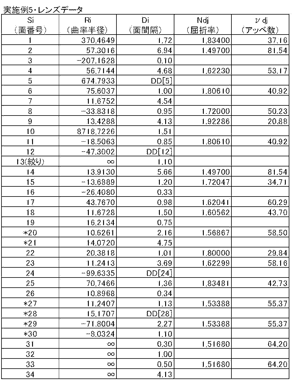


次に、実施例6のズームレンズについて説明する。実施例6のズームレンズのレンズ構成を示す断面図を図7に示す。
実施例6のズームレンズも、実施例1のズームレンズと同様の形状である。
また、実施例6のズームレンズの基本レンズデータを表21に、諸元に関するデータを表22に、移動面の間隔に関するデータを表23に、非球面係数に関するデータを表24に、各収差図を図13(A)~(L)に示す。
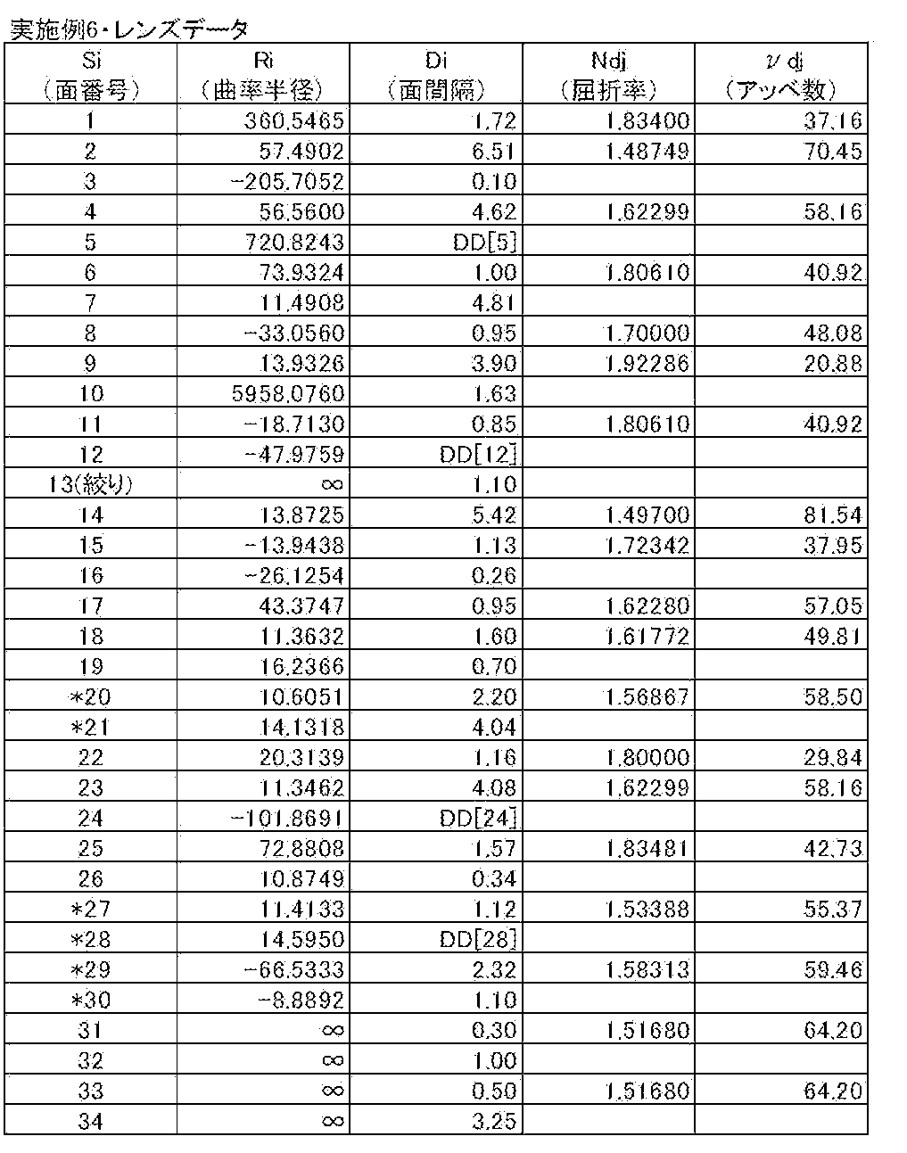



実施例1~6のズームレンズの条件式(1)~(6)に対応する値を表25に示す。なお、全実施例ともd線を基準波長としており、下記の表25に示す値はこの基準波長におけるものである。

以上のデータから、実施例1~6のズームレンズは全て、条件式(1)~(6)を満たしており、高変倍比でありながら、小型で、全変倍領域において諸収差が良好に補正されたズームレンズであることが分かる。
次に、本発明の実施形態にかかる撮像装置について説明する。図14に、本発明の実施形態の撮像装置の一例として、本発明の実施形態のズームレンズを用いた撮像装置の概略構成図を示す。なお、図14では各レンズ群を概略的に示している。この撮像装置としては、例えば、CCDやCMOS等の固体撮像素子を記録媒体とするビデオカメラや電子スチルカメラ等を挙げることができる。
図14に示す撮像装置10は、ズームレンズ1と、ズームレンズ1の像側に配置されたローパスフィルタ等の機能を有するフィルタ6と、フィルタ6の像側に配置された撮像素子7と、信号処理回路8とを備えている。撮像素子7はズームレンズ1により形成される光学像を電気信号に変換するものであり、例えば、撮像素子7としては、CCD(Charge Coupled Device)やCMOS(Complementary Metal Oxide Semiconductor)等を用いることができる。撮像素子7は、その撮像面がズームレンズ1の像面に一致するように配置される。
ズームレンズ1により撮像された像は撮像素子7の撮像面上に結像し、その像に関する撮像素子7からの出力信号が信号処理回路8にて演算処理され、表示装置9に像が表示される。
以上、実施形態および実施例を挙げて本発明を説明したが、本発明は上記実施形態および実施例に限定されず、種々の変形が可能である。例えば、各レンズ成分の曲率半径、面間隔、屈折率、アッベ数等の値は、上記各数値実施例で示した値に限定されず、他の値をとり得るものである。
Claims (24)
- 物体側から順に、正の屈折力を有する第1レンズ群、負の屈折力を有する第2レンズ群、正の屈折力を有する第3レンズ群、負の屈折力を有する第4レンズ群、正の屈折力を有する第5レンズ群からなり、
前記第3レンズ群は、最も物体側と最も像側に接合レンズを有し、
前記第4レンズ群は、物体側から順に負レンズ、正レンズからなり、
広角端から望遠端への変倍に際して、各レンズ群の間隔が変化し、前記第5レンズ群は固定され、少なくとも前記第1レンズ群および前記第4レンズ群は移動する
ことを特徴とするズームレンズ。 - 前記第3レンズ群の最も物体側の接合レンズに隣接する位置に開口絞りを配置した
ことを特徴とする請求項1記載のズームレンズ。 - 前記第1レンズ群および前記第4レンズ群は、望遠端において広角端よりも物体側に位置し、
下記条件式を満足する
ことを特徴とする請求項1または2記載のズームレンズ。
2.0<|D1|/|D4|<8.0 …(1)
ただし、
D1:前記第1レンズ群の広角端と望遠端における光軸上の位置の差
D4:前記第4レンズ群の広角端と望遠端における光軸上の位置の差
とする。 - 下記条件式を満足する
ことを特徴とする請求項1から3のいずれか1項記載のズームレンズ。
0.05<|f5|/ft<0.20 …(2)
ただし、
f5:前記第5レンズ群の焦点距離
ft:望遠端における全系の焦点距離
とする。 - 前記第3レンズ群全体あるいは該第3レンズ群に含まれる一部のレンズ群を光軸と垂直な方向に移動させて結像位置を変化させる
ことを特徴とする請求項1から4のいずれか1項記載のズームレンズ。 - 前記第3レンズ群の最も像側の接合レンズを光軸と垂直な方向に移動させて結像位置を変化させる
ことを特徴とする請求項1から5のいずれか1項記載のズームレンズ。 - 下記条件式を満足する
ことを特徴とする請求項1から6のいずれか1項記載のズームレンズ。
0.4<f3o/f3i<0.9 …(3)
ただし、
f3o:前記第3レンズ群の最も物体側の接合レンズの焦点距離
f3i:前記第3レンズ群の最も像側の接合レンズの焦点距離
とする。 - 前記第3レンズ群は、物体側から順に、開口絞り、正レンズと負レンズとの接合レンズ、負レンズと正レンズとの接合レンズ、正レンズ、負レンズと正レンズとの接合レンズからなる
ことを特徴とする請求項1から7のいずれか1項記載のズームレンズ。 - 下記条件式を満足する
ことを特徴とする請求項1から8のいずれか1項記載のズームレンズ。
0.30<|D4|/|f4|<1.00 …(4)
ただし、
D4:前記第4レンズ群の広角端と望遠端における光軸上の位置の差
f4:前記第4レンズ群の焦点距離
とする。 - 下記条件式を満足する
ことを特徴とする請求項1から9のいずれか1項記載のズームレンズ。
0.80<|f4|/|f5|<1.40 …(5)
ただし、
f4:前記第4レンズ群の焦点距離
f5:前記第5レンズ群の焦点距離
とする。 - 下記条件式を満足する
ことを特徴とする請求項1から10のいずれか1項記載のズームレンズ。
0.05<|f4|/ft<0.18 …(6)
ただし、
f4:前記第4レンズ群の焦点距離
ft:望遠端における全系の焦点距離
とする。 - 前記第4レンズ群を光軸方向に移動させることによりフォーカシングを行う
ことを特徴とする請求項1から11のいずれか1項記載のズームレンズ。 - 広角端から望遠端への変倍に際して、前記第2レンズ群および前記第3レンズ群は移動する
ことを特徴とする請求項1から12のいずれか1項記載のズームレンズ。 - 前記第5レンズ群は、像側に凸面を向けた1枚の正レンズからなる
ことを特徴とする請求項1から13のいずれか1項記載のズームレンズ。 - 前記第1レンズ群および前記第4レンズ群は、望遠端において広角端よりも物体側に位置し、
下記条件式を満足する
ことを特徴とする請求項1から14のいずれか1項記載のズームレンズ。
4.0<|D1|/|D4|<7.5 …(1-1)
ただし、
D1:前記第1レンズ群の広角端と望遠端における光軸上の位置の差
D4:前記第4レンズ群の広角端と望遠端における光軸上の位置の差
とする。 - 前記第1レンズ群および前記第4レンズ群は、望遠端において広角端よりも物体側に位置し、
下記条件式を満足する
ことを特徴とする請求項1から15のいずれか1項記載のズームレンズ。
4.5<|D1|/|D4|<7.0 …(1-2)
ただし、
D1:前記第1レンズ群の広角端と望遠端における光軸上の位置の差
D4:前記第4レンズ群の広角端と望遠端における光軸上の位置の差
とする。 - 下記条件式を満足する
ことを特徴とする請求項1から16のいずれか1項記載のズームレンズ。
0.07<|f5|/ft<0.11 …(2-1)
ただし、
f5:前記第5レンズ群の焦点距離
ft:望遠端における全系の焦点距離
とする。 - 下記条件式を満足する
ことを特徴とする請求項1から17のいずれか1項記載のズームレンズ。
0.09<|f5|/ft<0.10 …(2-2)
ただし、
f5:前記第5レンズ群の焦点距離
ft:望遠端における全系の焦点距離
とする。 - 下記条件式を満足する
ことを特徴とする請求項1から18のいずれか1項記載のズームレンズ。
0.5<f3o/f3i<0.8 …(3-1)
ただし、
f3o:前記第3レンズ群の最も物体側の接合レンズの焦点距離
f3i:前記第3レンズ群の最も像側の接合レンズの焦点距離
とする。 - 下記条件式を満足する
ことを特徴とする請求項1から19のいずれか1項記載のズームレンズ。
0.6<f3o/f3i<0.7 …(3-2)
ただし、
f3o:前記第3レンズ群の最も物体側の接合レンズの焦点距離
f3i:前記第3レンズ群の最も像側の接合レンズの焦点距離
とする。 - 下記条件式を満足する
ことを特徴とする請求項1から20のいずれか1項記載のズームレンズ。
0.50<|D4|/|f4|<0.80 …(4-1)
ただし、
D4:前記第4レンズ群の広角端と望遠端における光軸上の位置の差
f4:前記第4レンズ群の焦点距離
とする。 - 下記条件式を満足する
ことを特徴とする請求項1から21のいずれか1項記載のズームレンズ。
0.90<|f4|/|f5|<1.18 …(5-1)
ただし、
f4:前記第4レンズ群の焦点距離
f5:前記第5レンズ群の焦点距離
とする。 - 下記条件式を満足する
ことを特徴とする請求項1から22のいずれか1項記載のズームレンズ。
0.07<|f4|/ft<0.12 …(6-1)
ただし、
f4:前記第4レンズ群の焦点距離
ft:望遠端における全系の焦点距離
とする。 - 請求項1記載のズームレンズを備えたことを特徴とする撮像装置。
Priority Applications (3)
| Application Number | Priority Date | Filing Date | Title |
|---|---|---|---|
| JP2014535374A JP5745188B2 (ja) | 2012-09-14 | 2013-09-09 | ズームレンズおよび撮像装置 |
| CN201380047590.7A CN104620153B (zh) | 2012-09-14 | 2013-09-09 | 变焦镜头以及摄像装置 |
| US14/645,886 US9829686B2 (en) | 2012-09-14 | 2015-03-12 | Zoom lens and imaging apparatus |
Applications Claiming Priority (2)
| Application Number | Priority Date | Filing Date | Title |
|---|---|---|---|
| JP2012-202354 | 2012-09-14 | ||
| JP2012202354 | 2012-09-14 |
Related Child Applications (1)
| Application Number | Title | Priority Date | Filing Date |
|---|---|---|---|
| US14/645,886 Continuation US9829686B2 (en) | 2012-09-14 | 2015-03-12 | Zoom lens and imaging apparatus |
Publications (1)
| Publication Number | Publication Date |
|---|---|
| WO2014041786A1 true WO2014041786A1 (ja) | 2014-03-20 |
Family
ID=50277928
Family Applications (1)
| Application Number | Title | Priority Date | Filing Date |
|---|---|---|---|
| PCT/JP2013/005323 Ceased WO2014041786A1 (ja) | 2012-09-14 | 2013-09-09 | ズームレンズおよび撮像装置 |
Country Status (4)
| Country | Link |
|---|---|
| US (1) | US9829686B2 (ja) |
| JP (1) | JP5745188B2 (ja) |
| CN (1) | CN104620153B (ja) |
| WO (1) | WO2014041786A1 (ja) |
Cited By (4)
| Publication number | Priority date | Publication date | Assignee | Title |
|---|---|---|---|---|
| JP2016071179A (ja) * | 2014-09-30 | 2016-05-09 | コニカミノルタ株式会社 | ズームレンズ |
| JP2017116609A (ja) * | 2015-12-21 | 2017-06-29 | キヤノン株式会社 | ズームレンズ及びそれを有する撮像装置 |
| JP2017116610A (ja) * | 2015-12-21 | 2017-06-29 | キヤノン株式会社 | ズームレンズ及びそれを有する撮像装置 |
| JP2018155775A (ja) * | 2017-03-15 | 2018-10-04 | 富士フイルム株式会社 | ズームレンズおよび撮像装置 |
Families Citing this family (4)
| Publication number | Priority date | Publication date | Assignee | Title |
|---|---|---|---|---|
| JP6291406B2 (ja) * | 2014-12-02 | 2018-03-14 | 富士フイルム株式会社 | ズームレンズおよび撮像装置 |
| JP2017062318A (ja) * | 2015-09-24 | 2017-03-30 | オリンパス株式会社 | ズームレンズ及びそれを備えた撮像装置 |
| JP6685944B2 (ja) * | 2017-01-27 | 2020-04-22 | 富士フイルム株式会社 | ズームレンズおよび撮像装置 |
| CN111103677B (zh) * | 2020-01-08 | 2025-03-18 | 嘉兴中润光学科技股份有限公司 | 一种高清变焦镜头和安防摄像装置 |
Citations (6)
| Publication number | Priority date | Publication date | Assignee | Title |
|---|---|---|---|---|
| JP2001194590A (ja) * | 1999-10-29 | 2001-07-19 | Minolta Co Ltd | 撮像レンズ装置 |
| JP2001350093A (ja) * | 2000-04-07 | 2001-12-21 | Minolta Co Ltd | 撮像レンズ装置 |
| JP2007047538A (ja) * | 2005-08-11 | 2007-02-22 | Konica Minolta Photo Imaging Inc | 撮像光学系および撮像装置 |
| JP2007093979A (ja) * | 2005-09-28 | 2007-04-12 | Nikon Corp | ズームレンズ |
| JP2007093977A (ja) * | 2005-09-28 | 2007-04-12 | Nikon Corp | ズームレンズ |
| JP2011186417A (ja) * | 2009-07-23 | 2011-09-22 | Fujifilm Corp | ズームレンズおよび撮像装置 |
Family Cites Families (8)
| Publication number | Priority date | Publication date | Assignee | Title |
|---|---|---|---|---|
| US3556641A (en) * | 1966-06-30 | 1971-01-19 | Asahi Optical Co Ltd | Zoom lens system highly corrected for coma aberration |
| JP5023820B2 (ja) | 2007-06-07 | 2012-09-12 | コニカミノルタアドバンストレイヤー株式会社 | 防振機能を有するズームレンズ及び撮像装置 |
| JP5388446B2 (ja) * | 2007-12-05 | 2014-01-15 | キヤノン株式会社 | 光学系及びそれを有する光学機器 |
| JP5152490B2 (ja) * | 2007-12-25 | 2013-02-27 | 株式会社ニコン | 防振機能を有する変倍光学系、この変倍光学系を備えた光学機器、及び、変倍光学系の変倍方法 |
| EP2083303A1 (en) * | 2008-01-22 | 2009-07-29 | Nikon Corporation | Imaging lens, optical device thereof, and optical method for manufacturing imaging lens |
| JP5359025B2 (ja) | 2008-05-26 | 2013-12-04 | コニカミノルタ株式会社 | ズームレンズ |
| EP2360504B1 (en) * | 2010-02-24 | 2016-04-06 | Nikon Corporation | Zoom lens system, optical apparatus and method for manufacturing zoom lens system |
| WO2012101959A1 (ja) * | 2011-01-24 | 2012-08-02 | パナソニック株式会社 | ズームレンズ系、撮像装置及びカメラ |
-
2013
- 2013-09-09 WO PCT/JP2013/005323 patent/WO2014041786A1/ja not_active Ceased
- 2013-09-09 JP JP2014535374A patent/JP5745188B2/ja not_active Expired - Fee Related
- 2013-09-09 CN CN201380047590.7A patent/CN104620153B/zh not_active Expired - Fee Related
-
2015
- 2015-03-12 US US14/645,886 patent/US9829686B2/en not_active Expired - Fee Related
Patent Citations (6)
| Publication number | Priority date | Publication date | Assignee | Title |
|---|---|---|---|---|
| JP2001194590A (ja) * | 1999-10-29 | 2001-07-19 | Minolta Co Ltd | 撮像レンズ装置 |
| JP2001350093A (ja) * | 2000-04-07 | 2001-12-21 | Minolta Co Ltd | 撮像レンズ装置 |
| JP2007047538A (ja) * | 2005-08-11 | 2007-02-22 | Konica Minolta Photo Imaging Inc | 撮像光学系および撮像装置 |
| JP2007093979A (ja) * | 2005-09-28 | 2007-04-12 | Nikon Corp | ズームレンズ |
| JP2007093977A (ja) * | 2005-09-28 | 2007-04-12 | Nikon Corp | ズームレンズ |
| JP2011186417A (ja) * | 2009-07-23 | 2011-09-22 | Fujifilm Corp | ズームレンズおよび撮像装置 |
Cited By (4)
| Publication number | Priority date | Publication date | Assignee | Title |
|---|---|---|---|---|
| JP2016071179A (ja) * | 2014-09-30 | 2016-05-09 | コニカミノルタ株式会社 | ズームレンズ |
| JP2017116609A (ja) * | 2015-12-21 | 2017-06-29 | キヤノン株式会社 | ズームレンズ及びそれを有する撮像装置 |
| JP2017116610A (ja) * | 2015-12-21 | 2017-06-29 | キヤノン株式会社 | ズームレンズ及びそれを有する撮像装置 |
| JP2018155775A (ja) * | 2017-03-15 | 2018-10-04 | 富士フイルム株式会社 | ズームレンズおよび撮像装置 |
Also Published As
| Publication number | Publication date |
|---|---|
| JPWO2014041786A1 (ja) | 2016-08-12 |
| CN104620153B (zh) | 2017-03-08 |
| US20150185450A1 (en) | 2015-07-02 |
| JP5745188B2 (ja) | 2015-07-08 |
| CN104620153A (zh) | 2015-05-13 |
| US9829686B2 (en) | 2017-11-28 |
Similar Documents
| Publication | Publication Date | Title |
|---|---|---|
| CN104865683B (zh) | 变焦透镜以及摄像装置 | |
| JP5798255B2 (ja) | ズームレンズおよび撮像装置 | |
| JP6128387B2 (ja) | ズームレンズおよび撮像装置 | |
| JP5745188B2 (ja) | ズームレンズおよび撮像装置 | |
| JP6204852B2 (ja) | ズームレンズおよび撮像装置 | |
| JP5698869B2 (ja) | ズームレンズおよび撮像装置 | |
| CN104793323A (zh) | 变焦镜头以及摄像装置 | |
| JP6156848B2 (ja) | 変倍光学系および撮像装置 | |
| JP5860565B2 (ja) | ズームレンズおよび撮像装置 | |
| JP2016164629A (ja) | ズームレンズおよび撮像装置 | |
| WO2014147689A1 (ja) | ズームレンズおよび撮像装置 | |
| WO2013038610A1 (ja) | 変倍光学系および撮像装置 | |
| JP2016173482A (ja) | ズームレンズおよび撮像装置 | |
| JP2016071141A (ja) | ズームレンズおよび撮像装置 | |
| WO2017130480A1 (ja) | ズームレンズおよび撮像装置 | |
| WO2013031203A1 (ja) | 変倍光学系および撮像装置 | |
| JP6066419B2 (ja) | ズームレンズおよび撮像装置 | |
| WO2013031180A1 (ja) | ズームレンズおよび撮像装置 | |
| JP5229954B2 (ja) | ズームレンズおよび撮像装置 | |
| JP5118589B2 (ja) | ズームレンズおよび撮像装置 | |
| JP2010066661A (ja) | ズームレンズおよび撮像装置 | |
| JP5335373B2 (ja) | ズームレンズおよび撮像装置 | |
| JP5785333B2 (ja) | ズームレンズおよび撮像装置 | |
| JP5335352B2 (ja) | ズームレンズおよび撮像装置 | |
| JP2010072377A (ja) | ズームレンズおよび撮像装置 |
Legal Events
| Date | Code | Title | Description |
|---|---|---|---|
| 121 | Ep: the epo has been informed by wipo that ep was designated in this application |
Ref document number: 13837214 Country of ref document: EP Kind code of ref document: A1 |
|
| ENP | Entry into the national phase |
Ref document number: 2014535374 Country of ref document: JP Kind code of ref document: A |
|
| NENP | Non-entry into the national phase |
Ref country code: DE |
|
| 122 | Ep: pct application non-entry in european phase |
Ref document number: 13837214 Country of ref document: EP Kind code of ref document: A1 |