WO2014038047A1 - 電力変換装置 - Google Patents
電力変換装置 Download PDFInfo
- Publication number
- WO2014038047A1 WO2014038047A1 PCT/JP2012/072779 JP2012072779W WO2014038047A1 WO 2014038047 A1 WO2014038047 A1 WO 2014038047A1 JP 2012072779 W JP2012072779 W JP 2012072779W WO 2014038047 A1 WO2014038047 A1 WO 2014038047A1
- Authority
- WO
- WIPO (PCT)
- Prior art keywords
- reactor
- panel
- power
- back panel
- conversion device
- Prior art date
- Legal status (The legal status is an assumption and is not a legal conclusion. Google has not performed a legal analysis and makes no representation as to the accuracy of the status listed.)
- Ceased
Links
Images

Classifications
-
- H—ELECTRICITY
- H02—GENERATION; CONVERSION OR DISTRIBUTION OF ELECTRIC POWER
- H02M—APPARATUS FOR CONVERSION BETWEEN AC AND AC, BETWEEN AC AND DC, OR BETWEEN DC AND DC, AND FOR USE WITH MAINS OR SIMILAR POWER SUPPLY SYSTEMS; CONVERSION OF DC OR AC INPUT POWER INTO SURGE OUTPUT POWER; CONTROL OR REGULATION THEREOF
- H02M7/00—Conversion of AC power input into DC power output; Conversion of DC power input into AC power output
- H02M7/003—Constructional details, e.g. physical layout, assembly, wiring or busbar connections
Definitions
- the present invention relates to a power conversion device that converts DC power into AC power.
- power supply devices described in Patent Literature 1 and Patent Literature 2 are known.
- the casing is composed of a front panel, a side panel, a top panel, and a back panel. And this back panel turns into a surface (surface opposite to a wall surface) attached to the wall surface of a house, when fixing a power supply device to the wall surface of a house.
- a heat sink, a reactor, and the like constituting the power supply device are attached to the rear panel, and an electrical equipment box and the like are attached via the heat sink. That is, the main components constituting the power supply device are fixed to the back panel.
- the power supply device has a configuration in which main components are directly fixed to the back panel.
- Patent Document 1 and Patent Document 2 when a heavy component is fixed to the back panel, the back panel may be bent or twisted due to its weight. Cause trouble. However, if the thickness of the back panel is increased in order to prevent bending or the like, there are problems such as an increase in weight and inferior workability.
- vibration and noise may be increased when converting DC power to AC power.
- the present invention improves the workability when fixing heavy components by devising the shape of the back panel constituting the power converter, and can suppress the generation of vibration and noise during operation.
- An object is to provide a conversion device.
- a power converter includes a DC / DC converter circuit that boosts DC input power by having a first reactor, and an AC output from the DC / DC converter circuit that has a second reactor. And a DC / AC inverter circuit for converting the electric power, and at least the first reactor and the second reactor are arranged side by side, and are opposed to the first reactor and the second reactor of the rear panel of the housing having the rear panel screwed together. Each position is provided with a recessed portion that protrudes in the same direction as the tip of the screw higher than the tip of the screw at the time of screwing.
- a DC / DC converter circuit that has a first reactor and boosts the voltage of the DC power, and a second reactor in the power converter that converts DC power into AC power.
- a DC / AC inverter circuit that converts the output of the DC / DC converter circuit into the AC power, and at least a first panel and a second panel that are screwed side by side.
- the back panel is provided with a common recess that protrudes in the same direction as the front end of the screw at a position opposite to the first reactor and the second reactor on the back panel.
- FIG. 7 is a cross-sectional view taken along the line AA in FIG. 6. It is an external perspective view of ACL and DCL. It is a top view of the modification of a power converter device.
- the configuration of the power conversion apparatus according to the embodiment will be described with reference to FIGS.
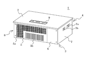
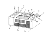
- the power conversion device 1 according to the embodiment has a substantially rectangular parallelepiped shape whose periphery is covered by a front panel 2, a back panel 3, a top panel 4, a bottom main panel 5, a bottom auxiliary panel 6, a right side panel 7 and a left side panel 8. It has a shape.
- the back panel 3 is attached to the wall surface (illustration omitted) so that the surface panel 2 side may become a front surface.
- the front panel 2 is shown in the upward direction for the convenience of drawing.
- the front panel 2 is made of metal or plastic, and is provided with a display unit 10 toward the front.
- the upper surface panel 4, the lower surface main panel 5, the lower surface auxiliary panel 6, the right side panel 7 and the left side panel 8 constitute a frame, and the surface panel 2 can be attached to and detached from the frame.
- the frame is made of a metal such as an iron plate, and is attached to the rear panel 3 which is also made of a metal such as an iron plate by screwing or welding. Details of the back panel 3 will be described later.
- the lower surface main panel 5 is formed with a ventilation hole 5a and a ventilation slit 5b, and a flow of cooling air is made corresponding to the ventilation hole 4a and the ventilation slit (not shown) of the upper surface panel 4, respectively.
- a heat sink 21 is disposed between the two ventilation slits, and air entering from the ventilation slit 5 b flows between the fins 21 a of the heat sink 21 toward the ventilation slit of the upper panel 4.
- the lower surface auxiliary panel 6 can be detached from the lower surface main panel 5.
- the right side panel 7 is appropriately provided with a power switch 7b, an AC outlet 7c, and the like.
- the heat sink 21 is fixed to the rear panel 3 with screws or the like.
- the main board 20 is mounted on the heat sink 21 at predetermined intervals via supports 23 and 23a (spacers).
- the switch element module 24 is constructed by incorporating a plurality of switch elements in a switch element fixing holder 25.
- the switch element fixing holder 25 is fixed onto the heat sink 21 through the opening 20c, thereby enabling the heat dissipation of the switch element to the heat sink 21.
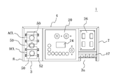
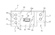
- a DC reactor DCL (first reactor) and an AC reactor ACL (second reactor) are arranged side by side on the left side panel 8 side of the heat sink 21.
- a sub-board 26 is disposed on the right side panel 7 side of the heat sink 21, and the sub-board 26 is an interconnection relay that performs electrical connection and disconnection between the AC output from the main board 20 and the system.
- a plurality of RLYs, here four, are provided.
- the sub-board 26 is attached to the back panel 3 by a support (not shown) whose one end is processed into a male screw shape. The details of the recess 50 formed in the back panel 3 will be described later.
- the power conversion apparatus 1 includes a first noise filter circuit CMF1 and a second noise filter circuit CMF2 that remove noise.
- the power converter 1 also includes a DC / DC converter circuit 36 that boosts the DC input power supplied from the solar cell module 30, and a DC that converts the DC power boosted by the DC / DC converter circuit 36 into AC power.
- An AC inverter circuit 37 is provided.
- the first noise filter circuit CMF1, the second noise filter circuit CMF2, the DC / DC converter circuit 36, and the DC / AC inverter circuit 37 are mainly provided on the main board.
- the switch element module 24 is formed by connecting three first to third arm circuits each having a parallel connection of a transistor and a freewheeling diode in series, and is connected to the arm circuit on the noise filter circuit CMF1 side.
- the DC / DC converter circuit 36 is configured by using the negative-side transistor, the DC reactor DCL, and the smoothing capacitor CON, and the inverter circuit 37 is configured by using the remaining two arm circuits.
- the input side of the DC reactor DCL is connected to the positive electrode of the solar cell module 30 via the first noise filter circuit CMF1, and the output side is the input side A point of the arm circuit (the connection point of the two switch elements of the arm circuit). Connected to.
- both ends B and C of the arm circuit are connected in parallel to the smoothing capacitor CON, and this point C is connected to the input side (DC side) of the DC / AC inverter circuit 37.
- the output point D and E point (AC side) of the DC / AC inverter circuit 37 are respectively connected to the AC reactor ACL.
- the direct current reactor DCL and the alternating current reactor ACL are required to have a large reactance with respect to a low frequency alternating current having a frequency of 50 Hz to 60 Hz. Even in the case of the home power converter 1 (the output is about 4 Kw to 6 Kw) as in the present embodiment, each has a weight of about 2 to 3 kg. Similarly, the smoothing capacitor CON also needs a large capacity.
- the DC power from the solar cell module 30 is input via the DC input terminals 17a and 17b. External noise is attenuated by the first noise filter circuit CMF1.
- the DC / DC converter circuit 36 boosts the input power and outputs the boosted power to the DC / AC inverter circuit 37.
- the DC / AC inverter circuit converts the input DC power into AC power synchronized with the commercial power system. It is superimposed on the commercial power system via the noise filter circuit CMF2 and the interconnection relays RLY1 to RLY4. Or it is output to a load.
- the back panel 3 will be described in detail. As described above, many components housed in the housing are attached to the back panel 3, and the back panel 3 is very useful when assembling the power converter 1 or using the power converter 1. Great power will be added. For this reason, the rear panel 3 is desired to have high mechanical strength. However, if the thickness of the rear panel 3 is simply increased, the weight of the power conversion device 1 increases or the processing of the rear panel 3 becomes difficult. For this reason, there is a limit to increasing the thickness of the back panel 3.
- a plurality of depressions are provided in the back panel 3 in order to increase the strength of the back panel 3.
- openings 3 b and 3 c for cooling the heat sink 21 are provided at the top and bottom of the metal back panel 3.
- the 1st panel part 61 and the connection part 63 which connects the 2nd panel part, the said 1st panel part, and the said 2nd panel part are formed on both sides of 3b and 3c.
- a total of five circular depressions 50 are provided in the first panel unit 61 and two in the second panel unit 62 by pressing. And this hollow part 50 is hollow toward the outer side of the back panel 3, as shown in FIG.
- first panel portion 61, the second panel portion 62, and the connecting portion 63 are an integral member made of a single sheet metal, but the first panel portion 61, the second panel portion 62, and the like.
- Each of the connecting portions 63 may be a separate member.
- a reinforcing member 51 is attached to the connecting portion 63 by a screw together with a convex portion by the hollow portion 50.
- the reinforcing member 51 and the connecting portion 63 are attached to the opposite side of the heat sink 21 at a position near the top panel 4 of the back panel 3, and increase the strength of the connecting portion 63 of the back panel 3, and the power conversion device 1.
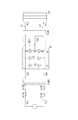
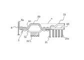
- It is a metal member that also serves as a fixing means when attaching to the wall surface. As shown in FIG. 7 (showing a cross-sectional view taken along the line AA in FIG. 6), the depth of the recess 50 is substantially flush with the height of the reinforcing member 51 (indicated by a broken line a). position).
- the covers other than the front panel 2 are first assembled to form a box-shaped housing.
- the back panel 3 is placed on a support table with the back panel 3 facing down, and various components are attached to the back panel 3.
- the recessed part 50 can contact
- the height of the reinforcing member 51 is substantially flush with the depth of the recess 50, it is possible to prevent the periphery of the recess 50 from being unnecessarily distorted.
- the direct current reactor DCL and the alternating current reactor ACL are not directly fixed to the back panel 3 by screwing but between the back panel 3 and the back panel 3.
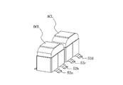
- the two installation members 52 (52a to 52d) are fixed to each other so as to form a space.
- the installation member 52 is an arch-shaped metal member, and places the reactor on the upper surface, and fixes the reactor on the placement member 52 by fixing means (not shown). Two through holes for passing screws are provided at the end of the installation member 52.
- the direct current reactor DCL and the alternating current reactor ACL are screwed into the screw holes 81 provided in the rear panel 3 through the through holes of the installation member 52 and are firmly fixed.
- the length of the screw is such that the tip of the screw does not exceed the depth of the recessed portion 50 when the reactor is attached.
- the screw holes 81 are disposed so as to surround the respective recessed portions 50 facing the DC reactor DCL and the AC reactor ACL, and transmit the weight of each reactor to the recessed portions 52 via the installation member 52. Is.
- the DC reactor DCL and the AC reactor ACL have a very high temperature in use because a large current flows. However, using such an arch-shaped installation member 52, a space is formed between the DC reactor DCL and the AC reactor ACL. By forming it, the DC reactors DCL and ACL are cooled by the air flow.
- the DC reactor DCL and the AC reactor ACL have a large current intermittently energized by switching by the switching element to generate vibration, but by fixing to the rear panel 3 using such an arch-shaped installation member 52, Although this vibration is partially absorbed, the remaining vibration is transmitted to the back panel 3 via the installation member 52.
- the vibration on the back panel 3 is attenuated by the pushing portion around the recess 50 and is prevented from spreading to the periphery. In particular, vibrations whose vibration center is located in the recess 50 are attenuated efficiently.
- the center of the DC reactor DCL or the AC reactor ACL is positioned in the hollow portion 50 when viewed from above (viewed from the top panel side), or a plurality of screw holes 81 for stopping the DC reactor DCL or the AC reactor ACL. It is preferable that the center of gravity of the figure with the apex is positioned in the recess 50.
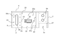
- the five recessed portions 50 are provided in the back panel 3 on the left side (first panel portion 61) and on the right side (second panel portion 62). .
- the three recessed portions 50 provided on the left side of the back panel 3 are located directly below the direct current reactor DCL, and are opposed to the alternating current reactor ACL. Thus, one is provided almost directly below, one between the DC reactor DCL and the AC reactor ACL.
- the back panel 3 is less likely to be bent or twisted around the hollow portion 50, and the displacement of the screw holes is suppressed. It becomes easy to do. Further, the vibration transmitted to the back panel 3 is attenuated at the recess and is difficult to be transmitted to the outside.
- the heat sink 21 occupying a large area among the components fixed to the back panel 3 is fixed in the middle of the back panel 3.
- the DC reactor DCL and the AC reactor ACL are fixed. Therefore, in the middle of the back panel 3 which is most easily bent, the heat sink 21 occupying a wide area is fixed, so that the back panel 3 as a whole is hardly bent.
- the heat sink 21 is fixed to the edge portions of the first panel portion and the second panel portion by screwing or the like, and the openings 3b and 3c are covered by the heat sink 21. Thereby, the heat sink 21 can be cooled, and the strength of the back panel 3 is increased by the heat sink 21 attached to the edge portions of the first panel portion 61 and the second panel portion 62, and the vibration suppressing effect and the like are improved.
- the two recessed portions 50 provided on the second panel portion 62 are formed on the left side 3 when the recessed portion 50 is formed on the back panel 3 by pressing. Since only one depression 50 is difficult to apply the pressure of the press uniformly to the substrate, it is provided in order to make the pressure in the press uniform. Therefore, the number of right side recesses 50 may be one. Moreover, if the structure which fixes a heavy component is employ
- the several hollow part 50 is provided, when this hollow part 50 is set
- the plurality of recesses 50 provided for reducing the vibration and noise generation of the back panel 3 can be used in combination for improving workability.
- the opening part 3b, 3c is provided in the center of the back panel 3, and the 1st panel part 61 and the 2nd panel part 62 are formed on both sides of this opening part 3b, 3c,
- the recessed portion 50 is provided in the first panel portion 61 and the second panel portion 62.
- the sub-board 26 is provided in the second panel portion 62 so as to face the recessed portion 50 provided in the second panel portion 62.
- This recess 50 increases the mechanical strength of the back panel 3 and makes it difficult for the sub-board 26 to bend when the sub-board 26 is attached to the back panel 3.
- the first panel unit 61 is provided with the direct current reactor DCL and the alternating current reactor ACL, and the hollow portions provided in the first panel portion 61 are more than the number of hollow portions 50 provided in the second panel portion 62.
- the number of 50 is increased.
- the dent 50 that is recessed toward the outside of the back panel 3 has been described, but the dent 50 may be recessed toward the inside of the back panel 3.
- the DC reactor DCL and the AC reactor ACL are installed via the installation member 50, and the hollow portion 50 is provided below the DC reactor DCL and the AC reactor ACL.
- the recessed portion 50 is configured to be recessed toward the inner side of the back panel 3, the space between the back panel 3 formed using the installation member 50 becomes narrow, and the cooling performance decreases. There is a risk of doing. Therefore, in such a case, a configuration in which the recessed portion 50 is recessed toward the outside of the back panel 3 as in the present embodiment is preferable.
- the circular recess 50 has been described, but it may be formed of other shapes such as a rectangular shape, an oval shape, an elliptical shape, and the like. Moreover, even if it is a rectangular shape, a corner
- the three recesses 50 are provided independently on the left side, but are not provided independently, but are not provided independently, but are common recesses facing the DC reactor DCL and the AC reactor ACL.
- a configuration in which one is provided may be used.
- FIG. 9 shows a plan view of a modification of the power converter.
- a vertically long recess 50a is provided as a common recess 50a.
- the shape of the common recess 50a is not limited to a vertically long shape, and various shapes such as a circular shape, an oval shape, and an elliptical shape can be used.
- the two dents on the right side may be constituted by one continuous dent.
- the openings 3b and 3c are provided in the center of the back panel 3 on which the heat sink 21 is disposed.
- the openings 3b and 3c are not provided, and the recess 50 is not provided (the surface is flat). ) Configuration is also possible.
- the recess 50 at the position of the heat sink 21, the surface of the back panel 3 becomes uniform at the position of the heat sink 21, so that a uniform cooling effect can be obtained.
Landscapes
- Engineering & Computer Science (AREA)
- Power Engineering (AREA)
- Inverter Devices (AREA)
Description
本発明は、直流電力を交流電力に変換する電力変換装置に関する。
近年、太陽電池、燃料電池、あるいは蓄電池などの直流電源の出力する直流電力を入力し、この直流電力を交流電力(例えば、商用電力系統と同期する交流電力)に変換する電力変換装置が提供されている。
この様な電力変換装置として、例えば、特許文献1や特許文献2に記載されている電源装置が知られている。特許文献1に記載されている電源装置は、その筐体が、フロントパネルと、側面パネルと、トップパネルと、背面パネルとから構成されている。そして、この背面パネルは、電源装置を家屋の壁面に固定する際に、家屋の壁面に取り付ける面(壁面と対向する面)となる。また、この背面パネルには、電源装置を構成するヒートシンクやリアクトル等が付けられ、またこのヒートシンクを介して電装ボックス等が取り付けられる。つまり、電源装置を構成する主な部品が背面パネルに固定される構成となっている。特許文献2においても、特許文献1と同様に、電源装置は、主な部品が背面パネルに直接固定される構成となっている。
上記特許文献1や特許文献2の記載によれば、背面パネルに、重量部品の固定作業の際にその重量で背面パネルが撓んだりねじれたりすることがあり螺子穴がずれたりし螺子止め作業に支障をきたす。しかしながら、撓み等を防止するために、背面パネルの板厚を厚くすると重量増加や加工性が劣る等の問題がある。
また、背面パネルの強度が足りないと直流電力を交流電力に変換する際に振動や騒音が大きくなることがある。
そこで、本発明は、電力変換装置を構成する背面パネルの形状を工夫することにより、重量部品を固定する際の作業性の向上と共に、運転時の振動や騒音の発生を抑制することのできる電力変換装置を提供することを目的とする。
上記目的を達成するため、本発明の電力変換装置は、第1リアクトルを有し直流入力電力を昇圧するDC/DCコンバータ回路と、第2リアクトルを有し前記DC/DCコンバータ回路の出力を交流電力に変換するDC/ACインバータ回路とを備えると共に、少なくとも第1リアクトル及び第2リアクトルが並んで螺子止めされる背面パネルを有する筺体の当該背面パネルの第1リアクトル及び第2リアクトルと相対向する位置に前記螺子止めの際の螺子の先端位置より高くこの螺子の先端と同方向に突出する窪み部を夫々備えることを特徴とする。
また、本発明の他の電力変換装置においては、直流電力を交流電力に変換する電力変換装置において、第1リアクトルを有し前記直流電力の電圧を昇圧するDC/DCコンバータ回路と、第2リアクトルを有し前記DC/DCコンバータ回路の出力を前記交流電力に変換するDC/ACインバータ回路とを備えると共に、少なくとも第1リアクトル及び第2リアクトルが並んで螺子止めされる背面パネルを有する筺体の当該背面パネルの第1リアクトル及び第2リアクトルと相対向する位置に前記螺子止めの際の螺子の先端位置より高くこの螺子の先端と同方向に突出する共通の窪み部を備えることを特徴とする。
本発明によれば、重量部品を固定する際の作業性を向上させると共に、運転時の振動や騒音の発生を抑制することができる。
以下に本発明を実施するための形態を、図面を用いて詳細に説明する。ただし、以下に示す各実施形態は、本発明の技術思想を理解するために電力変換装置を例示するものであって、本発明をこの電力変換装置に特定することを意図するものではなく、本発明は特許請求の範囲に示した技術思想を逸脱することなく種々の変更を行ったものにも均しく適用し得るものである。
実施形態の電力変換装置の構成を図1~図4を用いて説明する。実施形態の電力変換装置1は、表面パネル2、背面パネル3、上面パネル4、下面主パネル5、下面補助パネル6、右側面パネル7及び左側面パネル8によって周囲を覆われた略直方体状の形状を有している。なお、この電力変換装置1は、表面パネル2側が前面となるように、背面パネル3が壁面(図示省略)に取り付けられている。ただし、図1~図4においては、作図の都合上、表面パネル2が上方向となるように図示してある。
表面パネル2は、金属製又はプラスチック製であり、前方に向かって表示部10が設けられている。上面パネル4、下面主パネル5、下面補助パネル6、右側面パネル7及び左側面パネル8が枠体を構成し、この枠体に表面パネル2は取り付け及び取り外しが可能なように成されている。また、この枠体は鉄板等の金属で形成されており、同じく鉄板等の金属で形成されている背面パネル3に螺子止や溶接等によって取り付けられている。なお、背面パネル3については、詳細を後述する。
そして、下面主パネル5には通気孔5a及び通気スリット5bが形成されており、夫々上面パネル4の通気孔4a及び通気スリット(図示省略)に対応して冷却空気の流れを作っている。両通気スリット間には、ヒートシンク21が配置されこのヒートシンク21のフィン21aの間を通気スリット5bから入った空気が上面パネル4の通気スリットへ向かって流れるようになっている。また、下面補助パネル6は、下面主パネル5から取り外し可能でありなお、右側面パネル7には、適宜電源スイッチ7bやACコンセント7c等が設けられている。
ヒートシンク21は、背面パネル3に螺子止め等によって固定されている。
メイン基板20は、ヒートシンク21上に、サポート23、23a(スペーサ)を介して所定間隔で取り付けられている。
スイッチ素子モジュール24は、スイッチ素子固定用ホルダ25に複数のスイッチ素子を内蔵して成る。スイッチ素子固定用ホルダ25を開口20cを介してヒートシンク21上に固定することにより、スイッチ素子のヒートシンク21への放熱を可能にしている。
また、ヒートシンク21の左側面パネル8側には、図3に示したように、直流用リアクトルDCL(第1リアクトル)と、交流用リアクトルACL(第2リアクトル)とが並んで配置されている。さらに、ヒートシンク21の右側面パネル7側にはサブ基板26が配置されており、このサブ基板26にはメイン基板20からの交流出力と系統との間の電気的接続及び遮断を行う連系リレーRLYが複数個、ここでは4個設けられている。このサブ基板26は、一方の端部側がオス螺子状に加工されたサポート(図示省略)によって、背面パネル3に取り付けられている。なお、背面パネル3に形成されている窪み部50については詳細を後述する。
次に、実施形態の電力変換装置1の回路構成について、図5を用いて説明する。電力変換装置1は、ノイズを除去する第1のノイズフィルタ回路CMF1、第2のノイズフィルタ回路CMF2を有する。また、電力変換装置1は、太陽電池モジュール30から供給される直流の入力電力を昇圧するDC/DCコンバータ回路36、及びこのDC/DCコンバータ回路36が昇圧した直流電力を交流電力に変換するDC/ACインバータ回路37を備える。これらの第1のノイズフィルタ回路CMF1、第2のノイズフィルタ回路CMF2、DC/DCコンバータ回路36、及びDC/ACインバータ回路37は主にメイン基板上に設けられる。
ここで、スイッチ素子モジュール24は、それぞれトランジスタ及び還流ダイオードの並列回路を直列接続した第1~第3のアーム回路を3つ並列に接続したものであり、ノイズフィルタ回路CMF1の側のアーム回路の負極側のトランジスタと直流用リアクトルDCLと平滑コンデンサCONを用いてDC/DCコンバータ回路36を構成し、残りの2つのアーム回路を用いてインバータ回路37を構成している。
直流用リアクトルDCLの入力側は第1のノイズフィルタ回路CMF1を介して太陽電池モジュール30の正極に接続され、出力側はアーム回路の入力側A点(アーム回路の2つのスイッチ素子の接続点)に接続される。また、アーム回路の両端B点、C点を平滑コンデンサCONに並列に接続すると共に、このB点C点をDC/ACインバータ回路37の入力側(直流側)に接続する。また、DC/ACインバータ回路37の出力点D点及びE点(交流側)はそれぞれ交流用リアクトルACLに接続されている。
直流用リアクトルDCL及び交流用リアクトルACLは、周波数50Hzないし60Hzの低周波数交流に対するリアクタンスが大きいものが要求されるため、サイズが大きく、重くなる。なお、本実施形態のような家庭用の電力変換装置1(出力が4Kw~6Kw程度)の場合でも、それぞれ2~3kg程度の重量を有している。同様に、平滑コンデンサCONも大容量が必要である。
この様にすることで、太陽電池モジュール30からの直流電力は、直流入力端子17a、17bを介して入力される。外部からのノイズは第1のノイズフィルタ回路CMF1により減衰される。そして、DC/DCコンバータ回路36は、入力電力を昇圧してDC/ACインバータ回路37に出力し、DC/ACインバータ回路では入力された直流電力を商用電力系統と同期した交流電力に変換してノイズフィルタ回路CMF2、連系リレーRLY1~4を介して商用電力系統へ重畳される。又は負荷へ出力されるものである。
次に、背面パネル3について詳細に述べる。上述のように、筐体内に収容される多くの部品が、背面パネル3に取り付けられており、背面パネル3は、電力変換装置1を組み立てる際や、電力変換装置1を使用する際、非常に大きな力が加わることになる。そのため、背面パネル3には機械的強度の高いものが望まれるが、単に背面パネル3の板厚を厚くすると、電力変換装置1の重量が増えてしまったり、背面パネル3の加工が難しくなったりするため、背面パネル3の板厚を厚くすることにも限界がある。
そこで、本実施形態の電力変換装置1においては、背面パネル3の強度を高めるために、背面パネル3に複数の窪み部が設けられている。具体的には、図4や図6に示すように、金属製の背面パネル3の中央上下には、ヒートシンク21冷却用の開口部3b、3cが設けられ、背面パネル3には、この開口部3b、3cを挟んで第1パネル部61、及び第2パネル部と前記第1パネル部、及び前記第2パネル部とを繋ぐ連結部63が形成している。そして、プレス加工によって円形の窪み部50が第1パネル部61に3つ、第2パネル部62に2つ計5つ設けられている。そして、この窪み部50は、図6に示すように、背面パネル3の外側に向かって窪んでいる。なお、本実施形態においては、第1パネル部61と第2パネル部62と連結部63は、一枚の板金からなる一体の部材であるが、第1パネル部61と第2パネル部62と連結部63とは、それぞれが別の部材でも良い。
また、背面パネル3の外側には、この窪み部50による凸部とともに、補強部材51が螺子によって連結部63に取り付けられている。この補強部材51及び連結部63は、背面パネル3の上面パネル4寄りの位置で、ヒートシンク21の反対側に取り付けられており、背面パネル3の連結部63の強度を高めるとともに、電力変換装置1を壁面に取り付ける際の固定手段を兼ねている金属製の部材である。そして、図7(図6のA―Aの断面図を示している)に示すように、窪み部50の深さは、補強部材51の高さと略面一となっている(破線aで示す位置)。
電力変換装置1を組み立てる際には、通常、まず表面パネル2以外の各カバーを組み立てて、箱状の筐体をつくる。そして、次に背面パネル3を下にして支持台の上に置き、背面パネル3に各種の部品を取り付けていく。この時、窪み部50が支持台に当接して背面パネル3を略水平に保つことができる。この時、窪み部50に相対向して重量物(リアクトルなど)を置いてもその重量を窪み部50が直接支持するので背面パネル3が撓むことはない。また、補強部材51の高さを窪み部50の深さと略面一にしておくと、窪み部50の周辺が不必要に歪んだりすることを抑制できるものである。
また、図3や図8に示すように、本実施形態においては、直流用リアクトルDCLと交流用リアクトルACLは、背面パネル3に直接螺子止めにより固定されるのではなく、背面パネル3との間に空間が形成されるよう、設置部材52(52a~52d)をそれぞれ2つ用いて固定されている。設置部材52は、アーチ状の金属製部材であり、上面にリアクトルを載置し、図示しない固定手段によってリアクトルを載置部材52上に固定するものである。設置部材52の端部には螺子を通すための貫通孔が2つずつ設けられている。直流用リアクトルDCLと交流用リアクトルACLは、設置部材52の貫通孔に螺子を通して背面パネル3に設けられる螺子穴81に螺子止めして強固に固定される。この際、螺子の長さはリアクトルの取付時にその先端が窪み部50の深さを超えない長さである。また、螺子穴81は直流リアクトルDCLや交流リアクトルACLに相対向している夫々の窪み部50の周囲を囲むように配置され、設置部材52を介して夫々のリアクトルの重量を窪み部52に伝えるものである。直流用リアクトルDCLや交流用リアクトルACLは、大電流が流れるために、使用状態では非常に高温になるが、このようなアーチ状の設置部材52を用いて、背面パネル3との間に空間を形成しておくことで、空気の流れによって直流用リアクトルDCLとACLは、冷却されることになる。
また、直流用リアクトルDCLや交流用リアクトルACLは、スイッチング素子によるスイッチングで大電流が間欠通電され振動が生じるが、このようなアーチ状の設置部材52を用いて背面パネル3に固定することで、この振動が一部吸収されるが、残りの振動は設置部材52を介して背面パネル3に伝わる。この背面パネル3上の振動は窪み部50の周辺の押出部によって減衰し周辺へ広がるのが抑制される。特に振動の中心が窪み部50内に位置する振動は効率よく減衰される。例えば、直流用リアクトルDCLや交流用リアクトルACLの中心が上面視(上面パネル側から見て)で窪み部50内に位置させたり、直流用リアクトルDCLや交流用リアクトルACLを止める複数の螺子穴81を頂点とした図形の重心を窪み部50内に位置させたりすると良い。
上述のように、5つの窪み部50は、図4に示すように、背面パネル3において左側(第1パネル部61)に3つ、右側(第2パネル部62)に2つ設けられている。ここで、背面パネル3の左側に設けられている3つの窪み部50は、図3に示すように、直流用リアクトルDCLと相対向するように略真下に1つ、交流用リアクトルACLと相対向するように略真下に1つ、直流用リアクトルDCLと交流用リアクトルACLとの間に1つ設けられている。
このような構成によって窪み部50周辺では背面パネル3が撓みやねじれが生じ難くなり螺子穴のずれが抑制され、直流用リアクトルDCLや交流用リアクトルACLを背面パネル3に螺子止めする際、螺子止めしやすくなる。また背面パネル3に伝わった振動は窪み部で減衰し外部へ伝わり難くなる。
例えば、直流用リアクトルDCLと交流用リアクトルACLとの間側に位置する螺子(図8の場合、設置部材52bや設置部材52cを固定する螺子)を締める場合、一方の螺子を締めると、直流用リアクトルDCLと交流用リアクトルACLとの間で、背面パネル3に撓みやねじれが生じて螺子穴がずれてしまい、他方の螺子を締めることが困難になる。したがって、直流用リアクトルDCLと交流用リアクトルACLとの間に窪み部50を設けておくことにより、この部分の機械的強度が増し、背面パネル3の撓みやねじれが防止され、作業者は螺子止めしやすくなる。
また、例えば図4に示しているように、本実施形態の電力変換装置1では、背面パネル3に固定される部品の中で大きな面積を占めるヒートシンク21を背面パネル3の真ん中に固定し、その隣に、直流用リアクトルDCLと交流用リアクトルACLを固定する構成にしている。したがって、背面パネル3の中でも一番撓みやすい真ん中は、広い面積を占めるヒートシンク21が固定されることで、背面パネル3全体として撓み難くなっている。
また、ヒートシンク21は、第1パネル部、及び第2パネル部の縁部に螺子止め等により固定され、ヒートシンク21により開口部3b、3cが覆われている。これにより、ヒートシンク21が冷やせると共に、第1パネル部61、及び第2パネル部62の縁部に取り付けられたヒートシンク21によって背面パネル3の強度が増えて振動抑制効果などが向上する。
なお、本実施形態においては、第2パネル部62(右側面パネル7側)に設けられている2つの窪み部50は、背面パネル3に窪み部50をプレス加工により形成する際、左側の3つの窪み部50だけではプレスの圧力が基板に対して均一に加わり難いため、プレスの際の圧力を均一にするために設けているものである。したがって、右側の窪み部50は1つでも構わない。また、背面パネル3の右側においても重量部品を固定する構成を採用するのであれば、当然ながら、窪み部50は、背面パネル3の機械的強度を高めるものとして機能する。
また、本実施形態では、複数の窪み部50が設けられているため、この窪み部50を支持台におくと、複数の窪み部50が支持台に均等に当接するため、筐体は支持台上で安定し、作業者にとって組み立て作業が容易に行える。このように、背面パネル3の振動や騒音の発生を低減するために設けられた複数の窪み部50が作業性の向上をするために兼用することができる。
また、本実施形態では、背面パネル3の中央には、開口部3b、3cが設けられ、この開口部3b、3cを挟んで第1パネル部61、及び第2パネル部62とが形成され、窪み部50は、第1パネル部61と、第2パネル部62とに設けられている。これにより、複数の窪み部50の距離がはなれ、窪み部50を支持台において作業する際に更に安定性が増し作業者にとって組み立て作業が容易になる。
また、本実施形態では、第2パネル部62には、第2パネル部62に設けられる窪み部50にサブ基板26が相対向して設けられる。この窪み部50により背面パネル3の機械的強度が高まり、サブ基板26を背面パネル3に取り付ける際に撓み難くなっている。
また、本実施形態では、第1パネル部61に直流用リアクトルDCLと交流用リアクトルACLを設け、第2パネル部62に設けられる窪み部50の数よりも第1パネル部61に設けられる窪み部50の数を多くしている。これにより、振動の発生源である直流用リアクトルDCLと交流用リアクトルACLが取り付けられている側の背面パネル3の機械的強度をより強固なものにでき振動の抑制効果が向上する。
また、本実施形態では、背面パネル3の外側に向かって窪んでいる窪み部50を説明したが、窪み部50は背面パネル3の内側に向かって窪んでいるものでも構わない。しかしながら、本実施形態のような、設置部材50を介して直流用リアクトルDCLと交流用リアクトルACLを設置し、また、直流用リアクトルDCLと交流用リアクトルACLの下に窪み部50を設けておく構成の場合、窪み部50を、背面パネル3の内側に向かって窪む構成にしてしまうと、設置部材50を用いて形成した背面パネル3との間の空間が狭くなってしまい、冷却性が低下する虞がある。したがって、このような場合には、本実施形態のように、窪み部50が背面パネル3の外側に向かって窪んでいる構成が好ましい。
また、本実施形態では、円形状の窪み部50を説明したが、矩形状、長円形状、楕円形状等、他の形状からなるものでも構わない。また、矩形状であっても、角が直角である必要はなく、R付の角からなる矩形状でも構わない。
また、本実施形態では、左側に窪み部50が3つ、それぞれ独立して設けられているが、独立に設けるのではなく、直流用リアクトルDCL及び交流用リアクトルACLに相対向する共通の窪み部を一つ設ける構成でも構わない。図9に電力変換装置の変形例の平面図を示す。この図では、共通の窪み部50aとして、縦長形状の窪み部50aを設けている。尚、この共通の窪み部50aの形状は、縦長形状に限らず、円形状、長円形状、楕円形状等様々な形状を利用することができる。また、右側の2つの窪み部についても同様に、窪み部は連続する一つのもので構成されても構わない。
また、本実施形態では、ヒートシンク21を配置する背面パネル3の中央に開口部3b、3cを設けるようにしたが、開口部3b、3cを設けず、更に窪み部50を設けない(平面にする)構成としても良い。このようにヒートシンク21の位置には窪み部50を設けないことで、ヒートシンク21の位置では背面パネル3の表面が均一となるので、均一な冷却効果を得ることができる。
1…電力変換装置 2…表面パネル 3…背面パネル 3b、3c…開口部 4…上面パネル 5…下面主パネル 6…下面補助パネル 7…右側面パネル 8…左側面パネル 21…ヒートシンク 26…サブ基板 36…DC/DCコンバータ回路 37…DC/ACインバータ回路 DCL…直流用リアクトル(第1リアクトル) ACL…交流用リアクトル(第2リアクトル) RLY1~RLY4…連系リレー 50…窪み部 51…補強部材 52、52a~52d…設置部材 61…第1パネル部 62…第2パネル部 63…連結部
Claims (8)
- 直流電力を交流電力に変換する電力変換装置において、
第1リアクトルを有し前記直流電力の電圧を昇圧するDC/DCコンバータ回路と、第2リアクトルを有し前記DC/DCコンバータ回路の出力を前記交流電力に変換するDC/ACインバータ回路とを備えると共に、
少なくとも第1リアクトル及び第2リアクトルが並んで螺子止めされる背面パネルを有する筺体の当該背面パネルの第1リアクトル及び第2リアクトルと相対向する位置に前記螺子止めの際の螺子の先端位置より高くこの螺子の先端と同方向に突出する窪み部を夫々備えることを特徴とする電力変換装置。 - 第1リアクトル及び第2リアクトルに相対向している前記窪みは夫々のリアクトルから放射される振動の前記背面パネル上の中心を含む円形であることを特徴とする請求項1に記載の電力変換装置。
- 前記第1リアクトルと前記第2リアクトルとの間に前記窪み部を設けたことを特徴とする請求項1又は請求項2に記載の電力変換装置。
- 前記背面パネルの中央には、開口部が設けられ、この開口部を挟んで第1パネル部、及び第2パネル部とが形成され、
前記窪み部は、前記第1パネル部と、前記第2パネル部とに設けられることを特徴とする請求項1乃至請求項3の何れかにに記載の電力変換装置。 - 前記第2パネル部には、前記第2パネル部に設けられる窪み部に基板が相対向して設けられることを特徴とする請求項4に記載の電力変換装置。
- 前記DC/ACインバータ回路は、複数のスイッチ素子を有し、
前記複数のスイッチ素子を冷却するためのヒートシンクを備え、
前記開口部を形成する前記第1パネル部、及び前記第2パネル部の縁部に前記ヒートシンクを固定し、前記ヒートシンクにより前記開口部を覆うことを特徴とする請求項4又は請求項5に記載の電力変換装置。 - 前記第1パネル部に前記第1リアクトルと前記第2リアクトルを設け、前記第2パネル部に設けられる前記窪み部の数よりも前記第1パネル部に設けられる前記窪み部の数を多くしたことを特徴とする請求項1乃至請求項6の何れかに記載の電力変換装置。
- 直流電力を交流電力に変換する電力変換装置において、
第1リアクトルを有し前記直流電力の電圧を昇圧するDC/DCコンバータ回路と、第2リアクトルを有し前記DC/DCコンバータ回路の出力を前記交流電力に変換するDC/ACインバータ回路とを備えると共に、
少なくとも第1リアクトル及び第2リアクトルが並んで螺子止めされる背面パネルを有する筺体の当該背面パネルの第1リアクトル及び第2リアクトルと相対向する位置に前記螺子止めの際の螺子の先端位置より高くこの螺子の先端と同方向に突出する共通の窪み部を備えることを特徴とする電力変換装置。
Priority Applications (2)
| Application Number | Priority Date | Filing Date | Title |
|---|---|---|---|
| PCT/JP2012/072779 WO2014038047A1 (ja) | 2012-09-06 | 2012-09-06 | 電力変換装置 |
| JP2014534110A JP5879497B2 (ja) | 2012-09-06 | 2012-09-06 | 電力変換装置 |
Applications Claiming Priority (1)
| Application Number | Priority Date | Filing Date | Title |
|---|---|---|---|
| PCT/JP2012/072779 WO2014038047A1 (ja) | 2012-09-06 | 2012-09-06 | 電力変換装置 |
Publications (1)
| Publication Number | Publication Date |
|---|---|
| WO2014038047A1 true WO2014038047A1 (ja) | 2014-03-13 |
Family
ID=50236696
Family Applications (1)
| Application Number | Title | Priority Date | Filing Date |
|---|---|---|---|
| PCT/JP2012/072779 Ceased WO2014038047A1 (ja) | 2012-09-06 | 2012-09-06 | 電力変換装置 |
Country Status (2)
| Country | Link |
|---|---|
| JP (1) | JP5879497B2 (ja) |
| WO (1) | WO2014038047A1 (ja) |
Cited By (1)
| Publication number | Priority date | Publication date | Assignee | Title |
|---|---|---|---|---|
| JP2018207084A (ja) * | 2017-06-09 | 2018-12-27 | 株式会社タムラ製作所 | リアクトル装置 |
Families Citing this family (1)
| Publication number | Priority date | Publication date | Assignee | Title |
|---|---|---|---|---|
| JP5987163B2 (ja) * | 2012-09-07 | 2016-09-07 | パナソニックIpマネジメント株式会社 | 電力変換装置 |
Citations (2)
| Publication number | Priority date | Publication date | Assignee | Title |
|---|---|---|---|---|
| JP2010148195A (ja) * | 2008-12-17 | 2010-07-01 | Fuji Electric Systems Co Ltd | 電力変換装置 |
| JP2012060027A (ja) * | 2010-09-10 | 2012-03-22 | Yaskawa Electric Corp | 電子機器装置 |
-
2012
- 2012-09-06 JP JP2014534110A patent/JP5879497B2/ja active Active
- 2012-09-06 WO PCT/JP2012/072779 patent/WO2014038047A1/ja not_active Ceased
Patent Citations (2)
| Publication number | Priority date | Publication date | Assignee | Title |
|---|---|---|---|---|
| JP2010148195A (ja) * | 2008-12-17 | 2010-07-01 | Fuji Electric Systems Co Ltd | 電力変換装置 |
| JP2012060027A (ja) * | 2010-09-10 | 2012-03-22 | Yaskawa Electric Corp | 電子機器装置 |
Cited By (2)
| Publication number | Priority date | Publication date | Assignee | Title |
|---|---|---|---|---|
| JP2018207084A (ja) * | 2017-06-09 | 2018-12-27 | 株式会社タムラ製作所 | リアクトル装置 |
| JP7079571B2 (ja) | 2017-06-09 | 2022-06-02 | 株式会社タムラ製作所 | リアクトル装置 |
Also Published As
| Publication number | Publication date |
|---|---|
| JP5879497B2 (ja) | 2016-03-08 |
| JPWO2014038047A1 (ja) | 2016-08-08 |
Similar Documents
| Publication | Publication Date | Title |
|---|---|---|
| JP5141815B1 (ja) | 電力変換装置 | |
| JP5344013B2 (ja) | 電力変換装置 | |
| US10892508B2 (en) | Fuel cell unit | |
| JP5527354B2 (ja) | 電力変換装置 | |
| JP5338639B2 (ja) | 電力変換装置 | |
| JP6303130B2 (ja) | 電力変換装置 | |
| JP6252688B2 (ja) | パワーコンディショナ | |
| JP2016119816A (ja) | 電力変換装置 | |
| JP2007336761A (ja) | 電力変換装置 | |
| JP5987163B2 (ja) | 電力変換装置 | |
| JP4552513B2 (ja) | 電力制御ユニットおよびこれのユニットケース | |
| JP5879497B2 (ja) | 電力変換装置 | |
| JP6492822B2 (ja) | 回転電機構造 | |
| JP5445446B2 (ja) | 電力変換装置 | |
| JP6028222B2 (ja) | 電気機器 | |
| JP6019991B2 (ja) | 電力変換装置 | |
| JP5994717B2 (ja) | 電力変換装置 | |
| JP7320724B2 (ja) | 筐体、それを備える電気機器、及び電力変換装置 | |
| JP2022087928A (ja) | 機電一体ユニット | |
| JP2015126640A (ja) | 電力変換装置 | |
| JP5909664B2 (ja) | 電力変換装置 | |
| JP2018174611A (ja) | 電力変換装置 | |
| JP2016021817A (ja) | 電力変換装置 | |
| JP2018037218A (ja) | 電池モジュール | |
| JP6870458B2 (ja) | 電力変換装置 |
Legal Events
| Date | Code | Title | Description |
|---|---|---|---|
| 121 | Ep: the epo has been informed by wipo that ep was designated in this application |
Ref document number: 12884176 Country of ref document: EP Kind code of ref document: A1 |
|
| ENP | Entry into the national phase |
Ref document number: 2014534110 Country of ref document: JP Kind code of ref document: A |
|
| NENP | Non-entry into the national phase |
Ref country code: DE |
|
| 122 | Ep: pct application non-entry in european phase |
Ref document number: 12884176 Country of ref document: EP Kind code of ref document: A1 |