WO2014034945A1 - デジタルカメラ、情報処理方法およびコンピュータプログラム - Google Patents
デジタルカメラ、情報処理方法およびコンピュータプログラム Download PDFInfo
- Publication number
- WO2014034945A1 WO2014034945A1 PCT/JP2013/073664 JP2013073664W WO2014034945A1 WO 2014034945 A1 WO2014034945 A1 WO 2014034945A1 JP 2013073664 W JP2013073664 W JP 2013073664W WO 2014034945 A1 WO2014034945 A1 WO 2014034945A1
- Authority
- WO
- WIPO (PCT)
- Prior art keywords
- conversion
- density
- raw data
- parameter
- digital camera
- Prior art date
- Legal status (The legal status is an assumption and is not a legal conclusion. Google has not performed a legal analysis and makes no representation as to the accuracy of the status listed.)
- Ceased
Links
Images



Classifications
-
- H—ELECTRICITY
- H04—ELECTRIC COMMUNICATION TECHNIQUE
- H04N—PICTORIAL COMMUNICATION, e.g. TELEVISION
- H04N5/00—Details of television systems
- H04N5/222—Studio circuitry; Studio devices; Studio equipment
- H04N5/262—Studio circuits, e.g. for mixing, switching-over, change of character of image, other special effects ; Cameras specially adapted for the electronic generation of special effects
- H04N5/2621—Cameras specially adapted for the electronic generation of special effects during image pickup, e.g. digital cameras, camcorders, video cameras having integrated special effects capability
-
- H—ELECTRICITY
- H04—ELECTRIC COMMUNICATION TECHNIQUE
- H04N—PICTORIAL COMMUNICATION, e.g. TELEVISION
- H04N23/00—Cameras or camera modules comprising electronic image sensors; Control thereof
- H04N23/60—Control of cameras or camera modules
- H04N23/63—Control of cameras or camera modules by using electronic viewfinders
-
- H—ELECTRICITY
- H04—ELECTRIC COMMUNICATION TECHNIQUE
- H04N—PICTORIAL COMMUNICATION, e.g. TELEVISION
- H04N23/00—Cameras or camera modules comprising electronic image sensors; Control thereof
- H04N23/80—Camera processing pipelines; Components thereof
- H04N23/84—Camera processing pipelines; Components thereof for processing colour signals
- H04N23/843—Demosaicing, e.g. interpolating colour pixel values
-
- H—ELECTRICITY
- H04—ELECTRIC COMMUNICATION TECHNIQUE
- H04N—PICTORIAL COMMUNICATION, e.g. TELEVISION
- H04N5/00—Details of television systems
- H04N5/76—Television signal recording
- H04N5/765—Interface circuits between an apparatus for recording and another apparatus
- H04N5/77—Interface circuits between an apparatus for recording and another apparatus between a recording apparatus and a television camera
-
- H—ELECTRICITY
- H04—ELECTRIC COMMUNICATION TECHNIQUE
- H04N—PICTORIAL COMMUNICATION, e.g. TELEVISION
- H04N25/00—Circuitry of solid-state image sensors [SSIS]; Control thereof
- H04N25/10—Circuitry of solid-state image sensors [SSIS]; Control thereof for transforming different wavelengths into image signals
- H04N25/11—Arrangement of colour filter arrays [CFA]; Filter mosaics
- H04N25/13—Arrangement of colour filter arrays [CFA]; Filter mosaics characterised by the spectral characteristics of the filter elements
- H04N25/134—Arrangement of colour filter arrays [CFA]; Filter mosaics characterised by the spectral characteristics of the filter elements based on three different wavelength filter elements
Definitions
- the present invention relates to a digital camera, an information processing method, and a computer program.
- RGB three-color filters are photoelectrically converted using an image sensor to obtain RGB three-color image signals.
- the digital camera performs conversion such as Bayer interpolation, white balance conversion, matrix conversion, and ⁇ conversion on the obtained image signal to convert it into image data optimized for viewing on a display.
- the converted image data is recorded in a file format such as JPEG format.
- This image processing apparatus performs a white balance process, a color conversion matrix, and a gradation conversion process on an image photographed by a digital camera and subjected to the Bayer interpolation process in order to obtain a film-like image.
- the parameters of the white balance processing, color conversion matrix, and gradation conversion processing are optimized and processed so as to reproduce the film tone.
- the digital camera includes a RAW data conversion unit that converts a pixel value of each color of RAW data into a value corresponding to a predetermined spectral characteristic, and a spectral characteristic converted by the RAW data conversion unit.
- An output image conversion unit that converts a value corresponding to the above to predetermined output image data.
- the predetermined spectral characteristic is a spectral characteristic of each dye in the transparent original.
- the transparent original is preferably a photographic film.
- an information processing method includes a RAW data conversion step of converting pixel values of each color of RAW data into values corresponding to predetermined spectral characteristics, and a spectral data converted in the RAW data conversion step.
- the RAW data conversion step logarithmic conversion values are output by performing logarithmic conversion on the pixel values of each color of the RAW data, and the logarithm It is preferable that the converted value is converted into a density parameter indicating the density of each dye in the transparent original, and in the output image conversion step, the density parameter converted in the RAW data conversion step is converted into predetermined output image data.
- the spectral density characteristic of the transparent original corresponding to the density parameter is calculated, and based on the spectral density characteristic of the transparent original.
- the output image data is preferably device-dependent image data or device-independent image data.
- the logarithm conversion value is converted into a density parameter using predetermined conversion information, and the conversion information is: It is preferable that the color patch is generated based on photographing data obtained by photographing a color patch with a digital camera and colorimetric data obtained by measuring the color of a transparent original obtained by photographing the color patch.
- an information processing method is an information processing method for generating a lookup table for inputting RAW data captured by a digital camera and converting the data into predetermined color data.
- the logarithmic conversion step for outputting the logarithmic conversion value and the logarithmic conversion value output in the logarithmic conversion step are used as density parameters indicating the density of each dye in the transparent original.
- a density parameter conversion step for conversion a color data conversion step for converting the density parameter converted in the density parameter conversion step into device-dependent or device-independent color data, and a look at the color data converted in the color data conversion step Lookup table that generates a lookup table as the output value of the lookup table Having a generating step.
- the RAW data conversion unit outputs a logarithmic conversion value by performing logarithmic conversion on the pixel value of each color of the RAW data, and performs logarithmic conversion.
- the digital camera includes an imaging unit that captures a subject image, and a logarithmic conversion unit that outputs a logarithmic conversion value by performing logarithmic conversion on the RAW data captured by the imaging unit.
- a logarithm conversion value output from the logarithmic conversion unit is converted to a density parameter indicating the density of each dye in the transparent original; and a density parameter converted by the density parameter conversion unit is recorded on a recording medium.
- a RAW data input step for inputting RAW data picked up by a digital camera, and logarithmic conversion on the RAW data input in the RAW data input step are performed.
- the logarithmic conversion step for outputting the logarithmic conversion value, the density parameter conversion step for converting the logarithmic conversion value output in the logarithmic conversion step into a density parameter indicating the density of each dye in the transparent original, and the density parameter conversion step A recording step of recording the converted density parameter on a recording medium.
- an information processing method includes a density parameter input step for inputting a density parameter indicating the density of each dye in a transparent original, and a transmission parameter corresponding to the density parameter input in the density parameter input step.
- a spectral density characteristic calculating step for calculating the spectral density characteristic of the original; and an output image calculating step for calculating predetermined output image data based on the spectral density characteristic of the transparent original calculated in the spectral density characteristic calculating step.
- an information processing method is an information processing method for generating a lookup table for inputting a density parameter indicating the density of each dye in a transparent original and converting it into predetermined color data.
- the density parameter input step for inputting the density parameter
- the spectral density characteristic calculation step for calculating the spectral density characteristic of the transparent original corresponding to the density parameter input in the density parameter input step
- the spectral density characteristic calculation step for calculating the spectral density characteristic of the transparent original corresponding to the density parameter input in the density parameter input step
- a color data conversion step for converting the spectral density characteristics of the transmitted original into device-dependent or device-independent color data, and a lookup table using the color data converted in the color data conversion step as an output value of the lookup table. Generating a lookup table.
- a digital camera uses an imaging unit that captures a subject image, and a logarithmic conversion value that is output by performing logarithmic conversion on the RAW data captured by the imaging unit.
- a storage unit that stores a conversion parameter for conversion into a density parameter indicating the concentration of each dye in the recording unit, and a recording control unit that records the RAW data captured by the imaging unit and the conversion parameter in association with each other on a recording medium.
- a recording control unit that records the RAW data captured by the imaging unit and the conversion parameter in association with each other on a recording medium.
- the method further includes a conversion parameter input step of inputting a conversion parameter recorded on a recording medium by the digital camera according to the fifteenth aspect,
- the logarithmic conversion value output in the logarithmic conversion step is preferably converted into a density parameter using the conversion parameter input in the conversion parameter input step.
- a RAW data input step for inputting RAW data imaged by a digital camera, and a RAW data input by the RAW data input step It is preferable to include an image conversion step of converting data using the lookup table generated in the lookup table generation step.
- the pixel value of each color of the RAW data is converted into a transmittance parameter indicating the transmittance of each dye in the transmissive document.
- the transmittance parameter converted in the RAW data conversion step is converted into predetermined output image data.
- the RAW data conversion unit converts the pixel value of each color of the RAW data into a transmittance parameter indicating the transmittance of each dye in the transmissive document.
- the output image conversion unit preferably converts the transmittance parameter converted by the RAW data conversion unit into predetermined output image data.
- a computer program causes a computer to execute the information processing method according to any one of fourth to ninth, 12 to 14, and 16 to 19.
- the appearance of a transparent original can be accurately reproduced from an image captured by a digital camera.
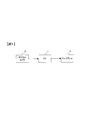
- FIG. 1 is a diagram illustrating a configuration example of an image processing system.
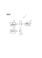
- FIG. 11 is a block diagram illustrating a configuration example of a personal computer. It is a block diagram explaining the structural example of a digital camera.
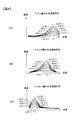
- (A) is a figure explaining the spectral density characteristic of a cyan layer
- (B) is a figure explaining the spectral density characteristic of a magenta layer
- (C) is a figure explaining the spectral density characteristic of a yellow layer.
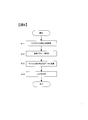
- 10 is a flowchart illustrating processing executed by a PC control device in the second embodiment.
- 10 is a flowchart illustrating processing executed by a PC control device in the second embodiment.
- FIG. 14 is a flowchart illustrating processing executed by a camera control device in the third embodiment.
- 10 is a flowchart illustrating processing executed by a PC control device in the third embodiment.
- 14 is a flowchart illustrating processing executed by a camera control device in the fourth embodiment.
- 10 is a flowchart illustrating processing executed by a PC control device in a fourth embodiment.
- 10 is a flowchart illustrating processing executed by a PC control device in a fifth embodiment. It is a figure explaining the structural example of PC of the modification 4.
- FIG. 14 is a flowchart for describing processing executed by a PC control device in Modification 8;
- 14 is a flowchart illustrating processing executed by a PC control device in Modification 9.
- 14 is a flowchart for describing processing executed by a PC control device in Modification 10;
- FIG. 1 is a diagram illustrating a configuration of an image processing system according to the first embodiment.
- a personal computer (PC) 1 is connected to an external device such as a digital camera 2 or a display 3 via a connection interface.
- the PC 1 performs image processing for converting photographed image data acquired from the digital camera 2 into an image that looks close to an image reproduced by a positive film (photographic film) (that is, a positive film-like image). , And output to the display 3. Details of this image processing will be described later.
- FIG. 2 is a block diagram illustrating a configuration example of the PC 1.
- the PC 1 includes a PC control device 10, a connection interface 11, and a storage medium 12 such as a hard disk.
- the PC 1 is connected to an external device such as the digital camera 2 and the display 3 via the connection interface 11.
- the connection interface 11 includes, for example, a USB interface that performs wired connection and a wireless LAN module that performs wireless connection.
- the PC control device 10 includes a CPU, a memory, and other peripheral circuits, and controls the operation of the PC 1 by executing a program stored in the memory.
- the PC control device 10 captures an image captured by the digital camera 2 from the memory card 26 (FIG. 3) attached to the digital camera 2 via the connection interface 11. Note that the PC control device 10 may capture an image captured by the digital camera 2 via a card interface (not shown) when a memory card on which an image captured by the digital camera 2 is recorded is attached to the PC 1.
- FIG. 3 is a block diagram illustrating a configuration example of the digital camera 2.
- the digital camera 2 includes an imaging optical system 20, an imaging element 21, a camera control device 22, a connection interface 23, a card interface 24, and a storage medium 25.
- a memory card 26 that is a removable recording medium is attached to the card interface 24.
- the digital camera 2 is connected to an external device such as the PC 1 (FIG. 1) via the connection interface 23.
- the connection interface 23 includes, for example, a USB interface that performs wired connection and a wireless LAN module that performs wireless connection.
- the camera control device 22 includes a CPU, a memory, and other peripheral circuits, and controls the operation of the digital camera 2 by executing a program stored in the memory.
- the imaging optical system 20 includes a plurality of lens groups including a zoom lens and a focusing lens, and forms a subject image on the light receiving surface of the imaging element 21.
- the imaging optical system 20 is illustrated as a single lens.
- the image sensor 21 is configured by a CMOS image sensor, for example.
- the image sensor 21 photoelectrically converts the subject image to generate an image signal.
- a well-known mosaic color filter is provided on the light receiving surface of the image sensor 21.
- the mosaic color filter has a mosaic arrangement (for example, a Bayer arrangement) in which primary color filters that pass light of any one of red (R), blue (B), and green (G) correspond to pixel positions.
- R red
- B blue
- G green
- Is a color separation filter constituted by The imaging element 21 outputs a color image signal for each of the three primary colors of light by capturing a subject image through such a color filter.
- the image signal generated by the image sensor 21 is converted into a digital signal by an A / D converter (not shown) and output to the camera control device 22 as RAW data.
- the camera control device 22 performs only Bayer interpolation processing on the RAW data and records it on the memory card 26 via the card interface 24.
- the positive film has a cyan dye layer, a magenta dye layer, a yellow dye layer, and a base layer. Therefore, the color of the positive film after development is large and can be considered to be determined by the characteristics obtained by adding the spectral density characteristics of the base to the spectral density characteristics of the cyan, magenta, and yellow dyes.
- the spectral density characteristic of the cyan layer is represented as Dc ( ⁇ )
- the spectral density characteristic of the magenta layer is represented as Dm ( ⁇ )
- the spectral density characteristic of the yellow layer is represented as Dy ( ⁇ )
- the spectral density characteristic of the base layer is represented as Db ( ⁇ ).
- the overall spectral density characteristic D ( ⁇ ) of the positive film can be expressed by the following formula (1).
- D ( ⁇ ) Dc ( ⁇ ) + Dm ( ⁇ ) + Dy ( ⁇ ) + Db ( ⁇ ) (1)
- the base spectral density characteristic Db ( ⁇ ) is always constant regardless of what kind of subject is photographed.
- the spectral density characteristics Dc ( ⁇ ), Dm ( ⁇ ), and Dy ( ⁇ ) of the cyan layer, magenta layer, and yellow layer are portions that vary depending on the subject, and this portion mainly constitutes the color of the image. Yes. For example, if the color of the photographed subject has a strong blue element, the spectral density characteristic Dc ( ⁇ ) of the cyan layer has a large value, and if the red element is strong, the spectral density characteristic Dm of the magenta layer and the yellow layer. ( ⁇ ) and Dy ( ⁇ ) are generally large values.
- the spectral density characteristics Dc ( ⁇ ), Dm ( ⁇ ), and Dy ( ⁇ ) of the cyan layer, magenta layer, and yellow layer are the strong colors of the subject. It is important to know how it changes.
- FIG. 4 shows the result of spectroscopic measurement of a chart created with 10 levels of density for each color.
- 4A shows the spectroscopic measurement result of the cyan chart
- FIG. 4B shows the spectroscopic measurement result of the magenta chart
- FIG. 4C shows the spectroscopic measurement result of the yellow chart. Note that the results shown in FIG. 4 are conceptual, not actual measurement values. Also, in FIG.
- the spectral density characteristics of each density in the cyan layer are Dc [1] ( ⁇ ) to Dc [10] ( ⁇ ), and the spectral density characteristics of each density in the magenta layer are Dm [1] ( ⁇ ) ⁇ Dm [10] ( ⁇ ) is assumed, and the spectral density characteristics of each density in the yellow layer are Dy [1] ( ⁇ ) to Dy [10] ( ⁇ ).
- [1] to [10] indicate the numbers (indexes) of the curves of the spectral density characteristics shown in FIG. 4, and the higher the value, the higher the density.
- the density parameter C indicates the density value of the cyan layer at the wavelength ⁇ c (for example, 660 nm) which is the peak density.
- ⁇ c for example, 660 nm
- the spectral density characteristic at the density parameter C 1.8.
- Dc (1.8, ⁇ ) is Dc [9] ( ⁇ ) itself.
- the spectral density characteristic Dc (C, ⁇ ) in the density parameter C can be obtained approximately.
- the spectral density characteristic Dc (C, ⁇ ) of the cyan layer at an arbitrary density parameter C is calculated from the spectral density characteristics Dc [1] ( ⁇ ) to Dc [10] ( ⁇ ) measured in advance.
- Dc [i] ( ⁇ ) and Dc [i + 1] ( ⁇ ) such that [i] ( ⁇ c) ⁇ C ⁇ Dc [i + 1] ( ⁇ c), and this Dc [i] ( ⁇ ) And Dc [i + 1] ( ⁇ ) can be approximately obtained by the following equation (2).
- Dc (C, ⁇ ) Dc [i] ( ⁇ ) + [(C-C1) / (C2-C1)] ⁇ [Dc [i + 1] ( ⁇ ) ⁇ Dc [i] ( ⁇ )] ( 2)
- the spectral density characteristic Dm (M, ⁇ ) of the magenta layer at the density parameter M indicating the density of the magenta layer is also approximated using Dm [1] ( ⁇ ) to Dm [10] ( ⁇ ) measured in advance. Can be obtained.
- the density parameter M indicates the density value of the magenta layer at the wavelength ⁇ m (for example, 540 nm) which is the peak density.
- Dy [1] ( ⁇ ) to Dy [10] ( ⁇ ) measured in advance are also used for the spectral density characteristic Dy (Y, ⁇ ) of the yellow layer in the density parameter Y indicating the density of the yellow layer.
- the density parameter Y indicates the density value of the yellow layer at the wavelength ⁇ y (for example, 440 nm) which is the peak density.
- the tristimulus values X, Y, and Z indicating the appearance are expressed based on the spectral characteristic I ( ⁇ ) of the observation light source and the overall spectral density characteristic D ( ⁇ ) of the positive film. It can be calculated by equations (3) to (5). In the following equations (3) to (5), x ( ⁇ ), y ( ⁇ ), and z ( ⁇ ) represent color matching functions.
- X ⁇ ⁇ I ( ⁇ ) ⁇ 10 ( ⁇ D ( ⁇ )) ⁇ x ( ⁇ ) ⁇ d ⁇ (3)
- Y ⁇ ⁇ I ( ⁇ ) ⁇ 10 ( ⁇ D ( ⁇ )) ⁇ y ( ⁇ ) ⁇ d ⁇ (4)
- Z ⁇ ⁇ I ( ⁇ ) ⁇ 10 ( ⁇ D ( ⁇ )) ⁇ z ( ⁇ ) ⁇ d ⁇ (5)
- the image data photographed by the digital camera 2 is converted into density parameters C, M, Y indicating the density of each color (cyan, magenta, yellow). It only has to be converted to.
- the density parameters C, M, and Y of each color are obtained, the spectral density characteristics Dc ( ⁇ ), Dm ( ⁇ ), and Dy ( ⁇ ) of each color are obtained, and the total spectral density characteristic D ( ⁇ ) of the positive film is obtained. Therefore, tristimulus values X, Y, and Z are obtained.
- the output device for example, the display 3
- an image obtained by converting the captured image of the digital camera 2 into a positive film tone is output to the output device. be able to. In this way, a positive film-like image can be reproduced from the image data photographed by the digital camera 2 in consideration of the physical characteristics of the positive film.
- a conversion matrix for converting image data (RAW data) taken by the digital camera 2 into density parameters C, M, and Y for each color (cyan, magenta, yellow) is created in advance.
- the RAW data used in the present embodiment is image data that has undergone only Bayer interpolation processing, and is image data that has not undergone image processing such as white balance conversion, color matrix conversion, and gradation conversion. To do.
- the RAW data is image data having linearity with respect to the amount of light (linear).
- the density is a value obtained by performing logarithmic transformation with 10 as the base with respect to the reciprocal of light reflectance (or transmittance).
- the RGB values are converted into a logarithmic space similar to the density by performing logarithmic conversion with the base 10 on the RGB values of the RAW data by the following equations (6) to (8). To do.
- the converted values are R 10 , G 10 , and B 10 .
- R 10 Log 10 R (6)
- G 10 Log 10 G (7)
- B 10 Log 10 B (8)
- a density conversion matrix for converting each color (cyan, magenta, yellow) into density parameters C, M, Y using the converted values R 10 , G 10 , B 10 is created.
- the conversion from R 10 , G 10 , B 10 to C, M, Y is performed by the following equation (9).
- coefficients m1 to m9 are transformation matrix parameters
- coefficients n1 to n3 are offset amounts.
- the offset amount is an amount corresponding to the value normalization.
- the optimization of the coefficients m1 to m9 and n1 to n3 is performed on both the color film consisting of a plurality of color patches, using both positive film and digital camera 2, and developing positive This can be performed based on both data of spectral colorimetry data of the film and image data taken by the digital camera 2.
- the total spectral density characteristic D ( ⁇ ) of the positive film can be expressed by Expression (1), and is determined by the density parameters C, M, and Y of each color.
- Dp ( ⁇ ) a result obtained by measuring the color patch portion with a spectral densitometer
- C, M, and Y in the color patch can be obtained by obtaining C, M, and Y that Dp ( ⁇ ) and D ( ⁇ ) are closest to each other.
- Dp ( ⁇ ) and D ( ⁇ ) is F
- F ⁇
- RAW data (RGB) of a certain color patch when the color chart is shot with the digital camera 2 is acquired, and logarithmic conversion is performed using equations (6) to (8).
- R 10 , G 10 , and B 10 in the color patch can be obtained.
- a set of C, M, Y and R 10 , G 10 , B 10 can be obtained for one color patch. Then, by photographing a plurality of color patches, a set of a plurality of C, M, Y and R 10 , G 10 , B 10 can be obtained. Therefore, the coefficients m1 to m9 and n1 to n3 of the equation (9) can be obtained based on the combination of the plurality of C, M, Y and R 10 , G 10 , B 10 . Specifically, R 10 , G 10 , B 10 obtained by taking a color patch with a digital camera 2 and logarithmically converted by Equation (9), and color patches are taken with a positive film and measured. The coefficients m1 to m9 and n1 to n3 that reduce the difference from C, M, and Y obtained by coloring are optimized using a least square method or the like.
- (Density conversion matrix) is stored in advance in the storage medium 12 of the PC 1.
- the spectral density characteristics Dc ( ⁇ ), Dm ( ⁇ ), Dy ( ⁇ ) and the base spectral density characteristics Db ( ⁇ ) of the positive film pigments (cyan, magenta, yellow) in a plurality of density parameters. (Hereinafter referred to as spectral density characteristic information) is also stored in the storage medium 12 of the PC 1 in advance.
- the PC 1 uses the information stored in the storage medium 12 to perform image processing for converting the image data captured by the digital camera 2 into a positive film tone image.
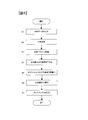
- step S1 the PC control device 10 inputs RAW data (RGB values) of the processing target pixel, and proceeds to step S2.
- step S2 the PC control device 10 performs logarithmic conversion on the RAW data (RGB values) input in step S1 using the above-described equations (6) to (8), and proceeds to step S3.
- step S3 the PC control device 10 converts the image data (R 10 , G 10 , B 10 ) converted in step S2 into density parameters C, M, and Y in the processing target pixel according to the above-described equation (9). After conversion, go to step S4.
- step S4 the PC controller 10 uses the density parameters C, M, and Y converted in step S3 and the spectral density characteristic information stored in the storage medium 12 to perform processing according to the above equation (2).
- the spectral density characteristics Dc ( ⁇ ), Dm ( ⁇ ), and Dy ( ⁇ ) of each color in the target pixel are calculated, and the process proceeds to step S5.
- step S5 the PC control device 10 calculates the total spectral density characteristic D ( ⁇ ) on the positive film in the processing target pixel by the above-described equation (1) using the calculation result in step S4. The process proceeds to step S6.
- step S6 the PC control device 10 uses the spectral density characteristic D ( ⁇ ) calculated in step S5, and the tristimulus values X, Y, Z is calculated, and the process proceeds to step S6.
- observation light source to be set in calculating tristimulus values X, Y, and Z may be, for example, a daylight such as D 50.
- the observation light source may be a light source for the projector, or may be a combination of the light source of the projector and the spectral reflectance of the screen. .
- step S7 the PC control device 10 uses the following equation (11) to calculate the tristimulus values X, Y, and Z calculated in step S6, and use a color space (RGB) that depends on the display 3 (device dependent). ).
- R 1, G 1, and B 1 each indicate a color space value that depends on the display 3.
- the coefficients a1 to a9 can be obtained from the primary color characteristics of the display 3.
- the PC control device 10 uses the following equations (12) to (14) for the values (R 1, G 1, B 1 ) converted into the color space (RGB) depending on the display 3 to perform ⁇ conversion Apply. Then, the process of FIG. In the following formulas (12) to (14), R 2, G 2, and B 2 each represent a value after ⁇ conversion.
- the function f can be obtained from the ⁇ characteristic of the display 3.
- R 2 f (R 1 ) (12)
- G 2 f (G 1 ) (13)
- B 2 f (B 1 ) (14)
- the PC control device 10 outputs the image data obtained by the processing of FIG. As a result, the image photographed by the digital camera 2 is converted into a positive film tone and displayed on the display 3.
- the computer program performs logarithmic conversion value (R) by performing logarithmic conversion on the RAW data input step for inputting the RAW data imaged by the digital camera 2 and the RAW data input in the RAW data input step.
- 10 , G 10 , B 10 ) and logarithmic conversion values output in the logarithmic conversion step are used as density parameters (C, M, Y) indicating the density of each dye in a transparent original (positive film).
- a computer (PC control device 10): a density parameter conversion step for converting to a density parameter; and an image output step for converting the density parameter converted in the density parameter conversion step to predetermined output image data (RGB data depending on the display). Was made to run.
- the film can be converted into a positive film tone in the same logarithmic space as the density of the positive film. Can be reproduced.
- the image output step includes a spectral density characteristic D of a transparent original (positive film) corresponding to the density parameter (C, M, Y) converted in the density parameter conversion step.
- Output image data RGB data depending on the display
- ⁇ ⁇
- D ⁇
- the logarithm conversion value is converted into density parameters (C, M, Y) using predetermined conversion information (density conversion matrix).
- the conversion information is generated based on photographing data obtained by photographing the color patch with the digital camera 2 and colorimetric data obtained by measuring the color of a transparent original (positive film) obtained by photographing the color patch.
- the RAW data imaged by the digital camera 2 can be appropriately converted into density parameters (C, M, Y).
- the PC control device 10 converts it to a positive film tone image as in the first embodiment described above, and L * a * b in the device-independent color space.
- a positive film conversion LUT generation process for generating a three-dimensional LUT (hereinafter referred to as a positive film conversion LUT) to be output as a value is executed. It is assumed that a computer program for causing the PC control device 10 to execute this positive film conversion LUT generation process is stored in a memory (not shown) in the PC control device 10, for example.
- the PC control device 10 In the positive film conversion LUT generation process, first, the PC control device 10 generates an input value of the positive film conversion LUT.
- the PC control device 10 obtains an output value for the generated input value. For example, when obtaining an output value for an input value (R [0], G [0], B [0]), the PC control device 10 uses the input value (R [0], G [0], B [0]). ]) Is converted into a positive film tone image by using the processing of steps S1 to S6 of FIG. 5 described above, and tristimulus values X, Y, and Z are obtained. The tristimulus values X, Y, and Z are converted into L * , a * , and b * using a known conversion formula.
- the PC control device 10 stores each input value and an output value set (input / output data set) as a positive film conversion LUT in the storage medium 12.
- the PC control device 10 uses the positive film conversion LUT generated in this way to convert the RAW data (RGB values) captured by the digital camera 2 into a positive film tone image L * a * b * value. Convert to The PC control device 10 converts the converted L * a * b * value into a color space (RGB value) that depends on the display 3. Note that the PC control device 10 performs this conversion, for example, based on a color profile in which the relationship between the color space L * a * b * that does not depend on the display 3 and the color space RGB that depends on the display 3 is described. .
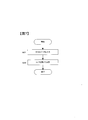
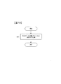
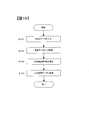
- FIG. 6 illustrates a process of generating a lookup table (positive film conversion LUT) for inputting RAW data imaged by the digital camera 2 and converting it into predetermined color data (L * a * b * ). It is a flowchart.
- step S ⁇ b> 11 the PC control device 10 performs logarithmic conversion on the input value of the lookup table, and outputs logarithmic conversion values (R 10 , G 10 , B 10 ).
- step S12 the PC control device 10 converts the logarithmic conversion value output in step S11 into a density parameter (C, M, Y) indicating the density of each pigment in the transparent original (positive film).
- step S13 the PC control apparatus 10 converts the density parameter converted in step 12 into device-independent color data (L * a * b * ).
- step S14 the PC control device 10 generates a lookup table (positive film conversion LUT) using the color data converted in step S13 as an output value of the lookup table.
- FIG. 7 is a flowchart for explaining processing for converting RAW data (RGB values) photographed by the digital camera 2 into a positive film tone image using a positive film conversion LUT.
- step S21 the PC control apparatus 10 inputs the RAW data imaged by the digital camera 2.
- step S22 the PC control device 10 converts the RAW data input in step S21 using the lookup table (positive film conversion LUT) generated in step S14.
- the computer program generates a look-up table (positive film conversion LUT) for inputting RAW data captured by the digital camera 2 and converting it into predetermined color data (L * a * b * ).
- a logarithmic conversion step that outputs logarithmic conversion values (R 10 , G 10 , B 10 ) by performing logarithmic conversion on the input value of the lookup table, and the logarithm output in the logarithmic conversion step
- a density parameter conversion step for converting the converted value into a density parameter (C, M, Y) indicating the density of each dye in the transparent original (positive film), and the density parameter converted in the density parameter conversion step are device-independent.
- a color data conversion step of converting the color data (L * a * b *) of Irode converted by the color data conversion step And so as to perform a look-up table generating step of generating a look-up table data as an output value of the lookup table to the computer (PC controller 10).
- the RAW data input step for inputting the RAW data imaged by the digital camera 2 and the RAW data input by the RAW data input step are generated in the lookup table generation step.
- the computer (PC control device 10) is further caused to perform an image conversion step of converting using a lookup table.
- the camera control device 22 records the density parameters C, M, and Y of each pixel on the memory card 26.
- the PC control device 10 of the PC 1 executes image processing described below in accordance with a computer program stored in a memory in the PC control device 10.
- the PC control device 10 inputs density parameters C, M, and Y of each pixel from the memory card 26 of the digital camera 2.
- the PC control device 10 converts the captured image data of the digital camera 2 into a positive film tone image by performing the above-described processing of steps S4 to S7 in FIG. 5 using the density parameters C, M, and Y. To do.
- the above-described density conversion matrix is stored in advance in the storage medium 25 of the digital camera 2, and the above-described spectral density characteristic information is stored in advance in the storage medium 12 of the PC 1. Shall.
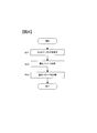
- FIG. 8 is a flowchart for explaining processing executed by the camera control device 22 of the digital camera 2 in the third embodiment.
- the camera control unit 22 by performing logarithmic transformation on the RAW data captured by the imaging device 21, and outputs the logarithmic conversion values (R 10, G 10, B 10).
- step S32 the camera control device 22 converts the logarithmic conversion value output in step S31 into a density parameter (C, M, Y) indicating the density of each pigment in the transparent original (positive film).
- step S33 the camera control device 22 records the density parameter converted in step S32 in the memory card 26.
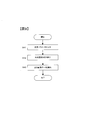
- FIG. 9 is a flowchart for explaining processing executed by the PC control device 10 of the PC 1 in the third embodiment.
- the PC control device 10 inputs the density parameter recorded on the memory card 26 by the digital camera 2.
- step S42 the PC control device 10 calculates the spectral density characteristic D ( ⁇ ) of the transmission original corresponding to the density parameter input in step S41.
- step S43 the PC control device 10 calculates predetermined output image data (RGB data depending on the display) based on the spectral density characteristic of the transmission original calculated in step 42.
- the digital camera 2 outputs logarithm conversion values (R 10 , G 10 , B 10 ) by performing logarithmic conversion on the image sensor 21 that captures the subject image and RAW data captured by the image sensor 21.
- the camera control device 22 the camera control device 22 that converts the output logarithmic conversion value into density parameters (C, M, Y) that indicate the density of each dye in the transmission original (positive film), and the converted And a camera control device 22 for recording the density parameter in the memory card 26.
- the computer program inputs a density parameter recorded in the memory card 26 by the digital camera 2 and a spectral density characteristic D (of the transparent original corresponding to the density parameter input in the density parameter input step.
- Spectral density characteristic calculation step for calculating ⁇ ) and output image calculation for calculating predetermined output image data (RGB data depending on the display) based on the spectral density characteristic of the transparent original calculated in the spectral density characteristic calculation step Step is executed by a computer (PC control device 10).
- a computer PC control device 10
- the appearance of the positive film can be reproduced from the image data photographed by the digital camera 2 with high accuracy.
- the computer program can be made the same program regardless of various cameras.
- the digital camera 2 records the density conversion matrix parameter information (coefficients a1 to a9, n1 to n3) in the same file as the RAW data. The case where it does is demonstrated. Note that in the fourth embodiment, a description of portions similar to those in the first to third embodiments is omitted.
- parameter information of the density conversion matrix is stored in the storage medium 25 in advance.
- the camera control device 22 reads out the parameter information of the density conversion matrix from the storage medium 25 when recording the RAW data on the memory card 26.
- the camera control device 22 records the read parameter information of the density conversion matrix in the same file as the RAW data as metadata of the RAW data.
- the PC control apparatus 10 When executing the image processing (steps S1 to S7 in FIG. 5) in the first embodiment described above, the PC control apparatus 10 obtains a RAW data file from the digital camera 2, thereby converting the density together with the RAW data. Get matrix parameter information. Then, the PC control apparatus 10 uses the acquired parameter information of the density conversion matrix to perform the process of step S3 in FIG.
- FIG. 10 is a flowchart for explaining processing executed by the camera control device 22 of the digital camera 2 in the fourth embodiment.
- the storage medium 25 of the digital camera 2 uses a logarithm conversion value output by performing logarithmic conversion on the RAW data imaged by the image sensor 21, and a density parameter indicating the density of each dye in a transparent original (positive film).
- the conversion parameter (parameter information of the density conversion matrix) for conversion into (1) is stored.
- step S ⁇ b> 51 of FIG. 10 the camera control device 22 records the RAW data imaged by the imaging element 21 and the conversion parameter stored in the storage medium 25 in association with each other and records them in the memory card 26.
- FIG. 11 is a flowchart for explaining processing executed by the PC control device 10 of the PC 1 in the fourth embodiment.
- the PC control apparatus 10 inputs RAW data and conversion parameters recorded on the memory card 26 by the digital camera 2.
- step S62 PC controller 10, by performing logarithmic transformation on the RAW data input in step 61, and outputs the logarithmic conversion values (R 10, G 10, B 10).
- step S63 the PC control device 10 converts the logarithmic conversion value output in step S62 into a density parameter (C, M, Y) using the conversion parameter input in step S61.
- step S64 the PC control device 10 converts the density parameter converted in step 63 into predetermined output image data (RGB data depending on the display).
- the digital camera 2 uses an image sensor 21 that captures a subject image, and a logarithmic conversion value output by performing logarithmic conversion on the RAW data captured by the image sensor 21, for each dye in a transparent original (positive film).
- a storage medium 25 that stores conversion parameters (concentration conversion matrix parameter information) for conversion into density parameters indicating the density of the image, and the RAW data captured by the image sensor 21 and the conversion parameters in association with each other in the memory card 26.
- a camera control device 22 for recording.
- the computer program performs logarithmic conversion by inputting log data and conversion parameters recorded in the memory card 26 by the digital camera 2 and logarithmically converting the raw data input in the input step.
- Logarithmic conversion step for outputting values (R 10 , G 10 , B 10 ), and logarithmic conversion values output in the logarithmic conversion step, using the conversion parameters input in the input step, concentration parameters (C, M, Y
- the computer includes: a density parameter conversion step that converts the image data into a color parameter conversion step; and an image output step that converts the density parameter converted in the density parameter conversion step into predetermined output image data (RGB data depending on the display). ) To be executed. Thereby, the appearance of the positive film can be reproduced with high accuracy from the image data photographed by the digital camera 2. Further, since it is not necessary to store the density conversion matrix of the digital camera 2 in the PC 1 that executes the computer program, it is possible to easily deal with captured images by various digital cameras 2.
- the digital camera 2 records the density conversion matrix parameter information (coefficients a1 to a9, n1 to n3) in the same file as the RAW data. The case where it does is demonstrated. Note that in the fifth embodiment, a description of portions similar to those in the first to fourth embodiments will be omitted.
- the digital camera 2 according to the fifth embodiment is the same as the digital camera 2 according to the fourth embodiment described above, and the camera control device 22 uses the parameter information of the density conversion matrix as metadata of the RAW data. Record in the same file as the RAW data.
- the PC control device 10 executes the positive film conversion LUT generation processing in the second embodiment described above, the PC control device 10 acquires the RAW data file from the digital camera 2 to obtain the density conversion matrix parameter information together with the RAW data. get. Then, the PC control apparatus 10 uses the acquired parameter information of the density conversion matrix to perform the process of step S3 in FIG.
- FIG. 12 shows a look-up table (positive film conversion LUT) for inputting RAW data captured by the digital camera 2 and converting it into predetermined color data (L * a * b * ) in the fifth embodiment. It is a flowchart explaining the process which produces
- the PC control apparatus 10 converts the logarithmic conversion value output by performing logarithmic conversion on the RAW data into a density parameter indicating the density of each dye in the transparent original (positive film). Parameters (parameter information of density conversion matrix) are input from the digital camera 2.
- step S ⁇ b> 72 the PC control device 10 performs logarithmic conversion on the input value of the lookup table, and outputs logarithmic conversion values (R 10 , G 10 , B 10 ).
- step S73 the PC control device 10 converts the logarithmic conversion value output in step S72 into a density parameter (C, M, Y) using the conversion parameter input in step S71.
- step S74 the PC control apparatus 10 converts the density parameter converted in step 74 into device-independent color data (L * a * b * ).
- step S75 the PC control device 10 generates a lookup table (positive film conversion LUT) using the color data converted in step S74 as an output value of the lookup table.
- the PC control device 10 converts the RAW data (RGB values) captured by the digital camera 2 into a positive film tone image using the positive film conversion LUT generated in step S75.
- the processing is performed in the same manner as the processing shown in FIG.
- the digital camera 2 uses an imaging element 21 that captures a subject image, and a logarithmic conversion value that is output by performing logarithmic conversion on the RAW data captured by the imaging element 21 as a transparent original (positive film).
- a storage medium 25 for storing conversion parameters (parameter information of the density conversion matrix) for converting into density parameters indicating the density of each dye in the memory, and RAW data imaged by the image sensor 21 and the conversion parameters in association with each other.
- a camera control device 22 for recording on the card 26.
- the computer program generates a look-up table (positive film conversion LUT) for inputting RAW data imaged by the digital camera 2 and converting it into predetermined color data (L * a * b * ).
- the conversion parameter input step for inputting the conversion parameter recorded in the memory card 26 by the digital camera 2 and the logarithmic conversion on the input value of the lookup table, the logarithmic conversion value (R 10 , G 10 , B 10 ), and the logarithmic conversion value output in the logarithmic conversion step is converted into a density parameter (C, M, Y) using the conversion parameter input in the conversion parameter input step.
- Density parameter conversion step and the density parameter converted in the density parameter conversion step Lookup to generate a look-up table and the color data conversion step of converting the device-independent color data (L * a * b *) , the converted color data in the color data conversion step as an output value of the lookup table
- the table generation step is executed by a computer (PC control device 10). Thereby, the appearance of the positive film can be reproduced with high accuracy from the image data photographed by the digital camera 2. Further, since it is not necessary to store the density conversion matrix of the digital camera 2 in the PC 1 that executes the computer program, it is possible to easily deal with captured images by various digital cameras 2.
- the RAW data input step for inputting the RAW data imaged by the digital camera 2 and the RAW data input by the RAW data input step are generated in the lookup table generation step.
- the computer (PC control device 10) is further caused to perform an image conversion step of converting using a lookup table.
- the camera control device 22 of the digital camera 2 executes the above-described processing of steps S1 to S7 in FIG. 5 using the RAW data obtained by the imaging device 21. Then, the camera control device 22 records the image data after the image processing on the memory card 26.
- the density conversion matrix and the positive film spectral density characteristic information are stored in advance in the storage medium 25 of the digital camera 2.
- the digital camera 2 outputs logarithm conversion values (R 10 , G 10 , B 10 ) by performing logarithmic conversion on the image sensor 21 that captures the subject image and RAW data captured by the image sensor 21.
- RGB data predetermined output image data
- Modification 1 In the embodiment described above, reproduction of various positive film brands may be realized.
- the processing is performed by replacing the spectral density characteristic information used in the process of step S4 in FIG. 5 described above with the spectral density characteristic information and conversion parameters (parameter information of the density conversion matrix) corresponding to the desired positive film brand.
- various positive film brands can be reproduced from one photographed image data by the digital camera 2.
- the color space of the output value of the positive film conversion LUT is the L * a * b * color space.
- the color space of the output value is not limited to this, and may be a color space such as an L * u * v * color space.
- the tristimulus values XYZ may be used as the output value of the positive film conversion LUT.
- the image output device is not limited to this, and may be a printer, for example.
- the image data (XYZ value or L * a * b * value, etc.) converted to positive film tone may be converted into a color space value according to the characteristics of the image output device.
- Modification 7 In the second and fifth embodiments described above, an example of generating an LUT that converts RAW data into device-independent color data (L * a * b * values) has been described. Alternatively, an LUT that is converted into a LUT may be generated.
- the PC control device 10 of the PC 1 inputs the RAW data from the digital camera 2 according to the computer program, performs the above-described steps S1 to S3 in FIG. 5, and calculates the density parameters C, M, and Y for each pixel.
- a process of recording the density parameters C, M, and Y of each pixel on a recording medium may be executed.
- the PC control device of another PC reads out the density parameters C, M, and Y from the recording medium, and performs the processing of steps S4 to S7 in FIG. You may make it convert into the image of a film tone.
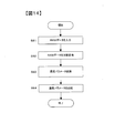
- FIG. 14 is a flowchart for explaining processing executed by the PC control device 10 of the PC 1 in the modified example 8.
- the PC control apparatus 10 inputs RAW data captured by the digital camera 2.
- step S82 the PC control apparatus 10 performs logarithmic conversion on the RAW data input in step S81 to output a logarithmic conversion value.
- step S83 the PC control device 10 converts the logarithmic conversion value output in step 82 into a density parameter indicating the density of each dye in the transparent original.
- step S84 the PC control device 10 records the density parameter converted in step S83 on the recording medium.
- the PC control device 10 of the PC 1 inputs density parameters C, M, and Y according to a computer program, and device-dependent color data (display RGB, etc.) or device-independent color data (L * a * b * value, etc.) ) May be executed.
- the PC control device 10 first generates input values (density parameters C, M, Y) of this LUT.
- the input value is, for example, a grid point obtained by dividing each data range of density parameters C, M, and Y at a plurality of levels at equal intervals. Then, the PC control device 10 uses the processing of steps S4 to S7 in FIG.
- the PC control device 10 generates a set of input values (density parameters C, M, and Y) and output values (color data) for the input values as LUTs, and stores them in the storage medium 12.
- the PC control device 10 reads out the density parameters C, M, and Y of each pixel recorded on the memory card 26 by the digital camera 2 in the third embodiment, and uses the generated LUT to set the density parameters.
- C, M, and Y are converted into color data (for example, display RGB). Thereby, a positive film tone image can be output to the display 3.
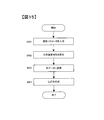
- FIG. 15 is a diagram illustrating modification example 9 in which density parameters C, M, and Y are input and device-dependent color data (display RGB, etc.) or device-independent color data (L * a * b * values, etc.) are output. It is a flowchart explaining the process which produces
- the PC control apparatus 10 inputs a density parameter.
- step S92 the PC control device 10 calculates the spectral density characteristic of the transparent original corresponding to the density parameter input in step S91.
- step S93 the PC control apparatus 10 converts the spectral density characteristics of the transparent original calculated in step S92 into device-dependent or device-independent color data.
- step S94 the PC control device 10 generates a lookup table using the color data converted in step S93 as the output value of the lookup table.
- the measurement values of the spectral density characteristics of the cyan, magenta, and yellow layers of the positive film as shown in FIG. 4 are prepared in advance, and the spectral density and density parameters of the cyan, magenta, and yellow layers are prepared.
- C, M, and Y are associated with each other.
- the correspondence (density conversion matrix) between the density parameters C, M, and Y and the RAW data is obtained from the color patch image data.
- the raw data of the captured image to be converted is converted into density parameters C, M, and Y using the correspondence (density conversion matrix) obtained in advance as described above. Convert.
- the tristimulus values XYZ are calculated from the spectral density characteristics corresponding to the converted density parameters C, M, and Y.
- image conversion based on spectral density characteristics it is possible to reproduce an image closer to the color tone of a positive film by image conversion based on spectral density characteristics.
- image conversion based on spectral density characteristics not only image conversion based on spectral density characteristics but also image conversion based on spectral transmittance characteristics can reproduce an image close to the color tone of a positive film.
- the measurement values of the spectral transmittance characteristics of the cyan, magenta, and yellow layers of the positive film are prepared in advance.
- a positive film is exposed so that the density of only one dye changes, and developed to create a chart, which is then measured spectroscopically.
- the transmittance parameters Ct, Mt, and Yt correspond to the spectral transmittances of the cyan, magenta, and yellow layers.
- the correspondence information between the transmittance parameters Ct, Mt, and Yt and the spectral transmittance characteristics of the dyes (cyan, magenta, yellow) of the positive film and the information on the spectral transmittance characteristics of the base of the positive film are spectrally transmitted.
- the rate characteristic information is stored in advance in the storage medium 12 of the PC 1.
- both photographing using a positive film and photographing using the digital camera 2 are performed. Then, based on both the data obtained by measuring the spectral transmittance of the positive film after development and the image data obtained by the digital camera 2, the correspondence between the RAW data and the transmittance parameters Ct, Mt, Yt is obtained.
- a transmittance conversion matrix for converting the RGB values of the RAW data into the transmittance parameters Ct, Mt, Yt of each color is obtained.
- Information on the correspondence between the RAW data and the transmittance parameters Ct, Mt, Yt is also stored in the storage medium 12 of the PC 1.
- FIG. 16 is a flowchart for explaining processing for converting RAW data into a positive film tone in the tenth modification.
- step S ⁇ b> 101 the PC control apparatus 10 inputs RAW data captured by the digital camera 2.
- step S102 the PC control device 10 converts the RGB values of the RAW data into transmittance parameters Ct, Mt, and Yt using the transmittance conversion matrix stored in the storage medium 12. Note that tone conversion for fine tone adjustment may be performed before step S102 and after step S101.
- step S103 the PC control device 10 determines the spectral transmittance characteristic Tc of the cyan layer based on the transmittance parameters Ct, Mt, Yt converted in step S102 and the spectral transmittance characteristic information stored in the storage medium 12.
- ( ⁇ ) the spectral transmittance characteristic Tm ( ⁇ ) of the magenta layer, and the spectral transmittance characteristic Ty ( ⁇ ) of the yellow layer are obtained.
- the PC control device 10 determines the spectral transmittance characteristics Tc ( ⁇ ), Tm ( ⁇ ), Ty ( ⁇ ) of each layer (cyan, magenta, yellow) and the base spectral transmittance characteristics Tb ( ⁇ ).
- the total spectral transmittance characteristic T ( ⁇ ) of the positive film is calculated by the following equation (15).
- T ( ⁇ ) Tc ( ⁇ ) ⁇ Tm ( ⁇ ) ⁇ Ty ( ⁇ ) ⁇ Tb ( ⁇ ) (15)
- step S104 the PC control device 10 calculates tristimulus values XYZ by the following equations (16) to (18) based on the total spectral transmittance characteristic T ( ⁇ ) of the positive film.
- I ( ⁇ ) indicates the spectral characteristics of the observation light source
- x ( ⁇ ), y ( ⁇ ), and z ( ⁇ ) indicate color matching functions.
- X ⁇ ⁇ I ( ⁇ ) ⁇ T ( ⁇ ) ⁇ x ( ⁇ ) ⁇ d ⁇ (16)
- Y ⁇ ⁇ I ( ⁇ ) ⁇ T ( ⁇ ) ⁇ y ( ⁇ ) ⁇ d ⁇ (17)
- Z ⁇ ⁇ I ( ⁇ ) ⁇ T ( ⁇ ) ⁇ z ( ⁇ ) ⁇ d ⁇ (18)
- the PC control device 10 converts the calculated tristimulus values XYZ into predetermined output image data (for example, RGB data depending on the display) using a predetermined conversion formula.
- image conversion based on the spectral transmittance characteristic can also reproduce an image closer to the color tone of the positive film, as in the case of using the spectral density characteristic as a base.
- the camera control device 22 of the digital camera 2 may perform the processing of steps S101 to S104 in FIG. 16 described above using the RAW data imaged by the imaging device 21.
Landscapes
- Engineering & Computer Science (AREA)
- Multimedia (AREA)
- Signal Processing (AREA)
- Facsimile Image Signal Circuits (AREA)
- Image Processing (AREA)
- Color Image Communication Systems (AREA)
- Color Television Image Signal Generators (AREA)
- Processing Of Color Television Signals (AREA)
- Television Signal Processing For Recording (AREA)
- Studio Devices (AREA)
Abstract
Description
本発明の第2の態様によると、第1の態様のデジタルカメラにおいて、所定の分光特性とは、透過原稿における各色素の分光特性であることが好ましい。
本発明の第3の態様によると、第2の態様のデジタルカメラにおいて、透過原稿は、写真フィルムであることが好ましい。
本発明の第4の態様によると、情報処理方法は、RAWデータの各色の画素値を、所定の分光特性に対応する値に変換するRAWデータ変換ステップと、RAWデータ変換ステップで変換された分光特性に対応する値を、所定の出力画像データに変換する出力画像変換ステップと、を有する。
本発明の第5の態様によると、第4の態様の情報処理方法において、RAWデータ変換ステップでは、RAWデータの各色の画素値に対して対数変換を施すことにより対数変換値を出力し、対数変換値を透過原稿における各色素の濃度を示す濃度パラメータに変換し、出力画像変換ステップでは、RAWデータ変換ステップで変換された濃度パラメータを、所定の出力画像データに変換することが好ましい。
本発明の第6の態様によると、第5の態様の情報処理方法において、出力画像変換ステップでは、濃度パラメータに対応する、透過原稿の分光濃度特性を算出し、透過原稿の分光濃度特性に基づいて、出力画像データを算出することが好ましい。
本発明の第7の態様によると、第4~6のいずれか一態様の情報処理方法において、出力画像データは、デバイス依存の画像データ、またはデバイス非依存の画像データであることが好ましい。
本発明の第8の態様によると、第5または6の態様の情報処理方法において、RAWデータ変換ステップでは、対数変換値を、所定の変換情報を用いて濃度パラメータに変換し、変換情報は、色パッチをデジタルカメラにより撮影した撮影データと当該色パッチを撮影した透過原稿を測色した測色データとに基づいて生成されることが好ましい。
本発明の第9の態様によると、情報処理方法は、デジタルカメラにより撮像されたRAWデータを入力して所定の色データに変換するためのルックアップテーブルを生成する情報処理方法であって、ルックアップテーブルの入力値に対して対数変換を施すことにより、対数変換値を出力する対数変換ステップと、対数変換ステップで出力された対数変換値を、透過原稿における各色素の濃度を示す濃度パラメータに変換する濃度パラメータ変換ステップと、濃度パラメータ変換ステップで変換された濃度パラメータを、デバイス依存またはデバイス非依存の色データに変換する色データ変換ステップと、色データ変換ステップで変換された色データをルックアップテーブルの出力値としてルックアップテーブルを生成するルックアップテーブル生成ステップと、を有する。
本発明の第10の態様によると、第1の態様のデジタルカメラにおいて、RAWデータ変換部は、RAWデータの各色の画素値に対して対数変換を施すことにより対数変換値を出力し、対数変換値を透過原稿における各色素の濃度を示す濃度パラメータに変換し、出力画像変換部は、RAWデータ変換部で変換された濃度パラメータを、所定の出力画像データに変換することが好ましい。
本発明の第11の態様によると、デジタルカメラは、被写体像を撮像する撮像部と、撮像部により撮像されたRAWデータに対して対数変換を施すことにより、対数変換値を出力する対数変換部と、対数変換部で出力された対数変換値を、透過原稿における各色素の濃度を示す濃度パラメータに変換する濃度パラメータ変換部と、濃度パラメータ変換部で変換された濃度パラメータを記録媒体に記録する記録制御部と、を備える。
本発明の第12の態様によると、情報処理方法は、デジタルカメラにより撮像されたRAWデータを入力するRAWデータ入力ステップと、RAWデータ入力ステップで入力されたRAWデータに対して対数変換を施すことにより、対数変換値を出力する対数変換ステップと、対数変換ステップで出力された対数変換値を、透過原稿における各色素の濃度を示す濃度パラメータに変換する濃度パラメータ変換ステップと、濃度パラメータ変換ステップで変換された濃度パラメータを記録媒体に記録する記録ステップと、を有する。
本発明の第13の態様によると、情報処理方法は、透過原稿における各色素の濃度を示す濃度パラメータを入力する濃度パラメータ入力ステップと、濃度パラメータ入力ステップで入力された濃度パラメータに対応する、透過原稿の分光濃度特性を算出する分光濃度特性算出ステップと、分光濃度特性算出ステップで算出された透過原稿の分光濃度特性に基づいて、所定の出力画像データを算出する出力画像算出ステップと、を有する。
本発明の第14の態様によると、情報処理方法は、透過原稿における各色素の濃度を示す濃度パラメータを入力して所定の色データに変換するためのルックアップテーブルを生成する情報処理方法であって、濃度パラメータを入力する濃度パラメータ入力ステップと、濃度パラメータ入力ステップで入力された濃度パラメータに対応する、透過原稿の分光濃度特性を算出する分光濃度特性算出ステップと、分光濃度特性算出ステップで算出された透過原稿の分光濃度特性を、デバイス依存またはデバイス非依存の色データに変換する色データ変換ステップと、色データ変換ステップで変換された色データをルックアップテーブルの出力値としてルックアップテーブルを生成するルックアップテーブル生成ステップと、を有する。
本発明の第15の態様によると、デジタルカメラは、被写体像を撮像する撮像部と、撮像部により撮像されたRAWデータに対して対数変換を施すことにより出力される対数変換値を、透過原稿における各色素の濃度を示す濃度パラメータに変換するための変換パラメータを記憶する記憶部と、撮像部により撮像されたRAWデータと変換パラメータとを対応づけて記録媒体に記録する記録制御部と、を備える。
本発明の第16の態様によると、第5の態様の情報処理方法において、RAWデータ変換ステップでは、第15の態様のデジタルカメラにより記録媒体に記録されたRAWデータの各色の画素値に対して対数変換を施すことにより対数変換値を出力し、対数変換値を、変換パラメータを用いて濃度パラメータに変換することが好ましい。
本発明の第17の態様によると、第9の態様の情報処理方法において、第15の態様のデジタルカメラにより記録媒体に記録された変換パラメータを入力する変換パラメータ入力ステップをさらに有し、濃度パラメータ変換ステップでは、対数変換ステップで出力された対数変換値を、変換パラメータ入力ステップで入力された変換パラメータを用いて濃度パラメータに変換することが好ましい。
本発明の第18の態様によると、第9または17の態様の情報処理方法において、さらに、デジタルカメラにより撮像されたRAWデータを入力するRAWデータ入力ステップと、RAWデータ入力ステップにより入力されたRAWデータを、ルックアップテーブル生成ステップで生成したルックアップテーブルを用いて変換する画像変換ステップと、を有することが好ましい。
本発明の第19の態様によると、第4の態様の情報処理方法において、RAWデータ変換ステップでは、RAWデータの各色の画素値を、透過原稿における各色素の透過率を示す透過率パラメータに変換し、出力画像変換ステップでは、RAWデータ変換ステップで変換された透過率パラメータを、所定の出力画像データに変換することが好ましい。
本発明の第20の態様によると、第1の態様のデジタルカメラにおいて、RAWデータ変換部は、RAWデータの各色の画素値を、透過原稿における各色素の透過率を示す透過率パラメータに変換し、出力画像変換部は、RAWデータ変換部で変換された透過率パラメータを、所定の出力画像データに変換することが好ましい。
本発明の第21の態様によると、コンピュータプログラムは、第4~9、12~14、16~19のいずれか一態様の情報処理方法をコンピュータに実行させる。
図面を参照して、本発明の第1の実施の形態について説明する。図1は、第1の実施の形態に係る画像処理システムの構成を例示する図である。パーソナルコンピュータ(PC)1は、接続インターフェースを介して、デジタルカメラ2やディスプレイ3などの外部装置と接続される。
図2は、PC1の構成例を説明するブロック図である。PC1は、PC制御装置10と、接続インターフェース11と、ハードディスクなどの記憶媒体12と、を備える。PC1は、接続インターフェース11を介して、デジタルカメラ2やディスプレイ3などの外部装置と接続される。接続インターフェース11は、たとえば、有線接続を行うUSBインターフェースや、無線接続を行う無線LANモジュールを含む。PC制御装置10は、CPU、メモリ、およびその他の周辺回路により構成され、メモリが記憶するプログラムを実行することによってPC1の動作を制御する。
図3は、デジタルカメラ2の構成例を説明するブロック図である。デジタルカメラ2は、撮像光学系20と、撮像素子21と、カメラ制御装置22と、接続インターフェース23と、カードインターフェース24と、記憶媒体25とを備える。カードインターフェース24には、着脱可能な記録媒体であるメモリカード26が装着される。
次に、上述したポジフィルム調の画像に変換する画像処理について説明する。まず、ポジフィルムの画像再現について考察する。ポジフィルムは、シアン色素の層と、マゼンタ色素の層と、イエロー色素の層と、ベース層とを有している。したがって、ポジフィルムの現像後の色は、大きく、シアン、マゼンタ、イエローの各色素の分光濃度特性に、ベースの分光濃度特性を加えた特性によって決定されると考えることができる。そのため、シアン層の分光濃度特性をDc(λ)、マゼンタ層の分光濃度特性をDm(λ)、イエロー層の分光濃度特性をDy(λ)、ベースの分光濃度特性をDb(λ)と表すと、ポジフィルムの総合的な分光濃度特性D(λ)は、次式(1)で表すことができる。
D(λ)=Dc(λ)+Dm(λ)+Dy(λ)+Db(λ) …(1)
Dc(1.9,λ)=?Dc[9](λ)?+?[(1.9-1.8)/(2.0-1.8)]・[Dc[10](λ)-Dc[9](λ)]
Dc(C,λ)=Dc[i](λ)+[(C-C1)/(C2-C1)]・[Dc[i+1](λ)-Dc[i](λ)] …(2)
X=∫{I(λ)・10(-D(λ))・x(λ)}dλ …(3)
Y=∫{I(λ)・10(-D(λ))・y(λ)}dλ …(4)
Z=∫{I(λ)・10(-D(λ))・z(λ)}dλ …(5)
R10=Log10R …(6)
G10=Log10G …(7)
B10=Log10B …(8)

F=Σ|D(λ)-Dp(λ)| …(10)

R2=f(R1) ・・・(12)
G2=f(G1) ・・・(13)
B2=f(B1) ・・・(14)
(1)コンピュータプログラムは、デジタルカメラ2により撮像されたRAWデータを入力するRAWデータ入力ステップと、RAWデータ入力ステップで入力されたRAWデータに対して対数変換を施すことにより、対数変換値(R10、G10、B10)を出力する対数変換ステップと、対数変換ステップで出力された対数変換値を、透過原稿(ポジフィルム)における各色素の濃度を示す濃度パラメータ(C、M、Y)に変換する濃度パラメータ変換ステップと、濃度パラメータ変換ステップで変換された濃度パラメータを、所定の出力画像データ(ディスプレイに依存するRGBデータ)に変換する画像出力ステップと、をコンピュータ(PC制御装置10)に実行させるようにした。このようにデジタルカメラ2で撮影されたRAWデータを対数変換することにより、ポジフィルムの濃度と同様の対数空間でポジフィルム調への変換を行うことができるので、従来よりも高精度にポジフィルムの見えを再現することができる。
第2の実施の形態では、RAWデータを、上述した第1の実施の形態と同様にポジフィルム調の画像へ変換するためのLUT(Look?Up?Table)を生成する場合について説明する。なお、第2の実施の形態において、第1の実施の形態と同様の箇所については説明を省略する。
(1)コンピュータプログラムは、デジタルカメラ2により撮像されたRAWデータを入力して所定の色データ(L*a*b*)に変換するためのルックアップテーブル(ポジフィルム変換LUT)を生成するコンピュータプログラムであって、ルックアップテーブルの入力値に対して対数変換を施すことにより、対数変換値(R10、G10、B10)を出力する対数変換ステップと、対数変換ステップで出力された対数変換値を、透過原稿(ポジフィルム)における各色素の濃度を示す濃度パラメータ(C、M、Y)に変換する濃度パラメータ変換ステップと、濃度パラメータ変換ステップで変換された濃度パラメータを、デバイス非依存の色データ(L*a*b*)に変換する色データ変換ステップと、色データ変換ステップで変換された色データをルックアップテーブルの出力値としてルックアップテーブルを生成するルックアップテーブル生成ステップとをコンピュータ(PC制御装置10)に実行させるようにした。これにより、デジタルカメラ2で撮影された画像データから高精度にポジフィルムの見えを再現することができる。
第3の実施の形態では、デジタルカメラ2が上述した図5のステップS3までの処理を実行し、ステップS4以降の処理を、PC1がコンピュータプログラムに従って実行する場合について説明する。なお、第3の実施の形態において、第1、第2の実施の形態と同様の箇所については説明を省略する。
デジタルカメラ2は、被写体像を撮像する撮像素子21と、撮像素子21により撮像されたRAWデータに対して対数変換を施すことにより、対数変換値(R10、G10、B10)を出力するカメラ制御装置22と、当該出力された対数変換値を、透過原稿(ポジフィルム)における各色素の濃度を示す濃度パラメータ(C、M、Y)に変換するカメラ制御装置22と、当該変換された濃度パラメータをメモリカード26に記録するカメラ制御装置22と、を備えるようにした。また、コンピュータプログラムは、デジタルカメラ2によりメモリカード26に記録された濃度パラメータを入力する濃度パラメータ入力ステップと、濃度パラメータ入力ステップで入力された濃度パラメータに対応する、透過原稿の分光濃度特性D(λ)を算出する分光濃度特性算出ステップと、分光濃度特性算出ステップで算出された透過原稿の分光濃度特性に基づいて、所定の出力画像データ(ディスプレイに依存するRGBデータ)を算出する出力画像算出ステップと、をコンピュータ(PC制御装置10)に実行させるようにした。これにより、デジタルカメラ2で撮影された画像データから、高精度にポジフィルムの見えを再現することができる。また、デジタルカメラ2において画像データの濃度パラメータを求めておくことにより、コンピュータプログラムを種々のカメラによらず同一のプログラムとすることができる。
第4の実施の形態では、上述した第1の実施の形態を前提として、デジタルカメラ2が濃度変換マトリクスのパラメータ情報(係数a1~a9、n1~n3)を、RAWデータと同一のファイルに記録する場合について説明する。なお、第4の実施の形態において、第1~第3の実施の形態と同様の箇所については説明を省略する。
デジタルカメラ2は、被写体像を撮像する撮像素子21と、撮像素子21により撮像されたRAWデータに対して対数変換を施すことにより出力される対数変換値を、透過原稿(ポジフィルム)における各色素の濃度を示す濃度パラメータに変換するための変換パラメータ(濃度変換マトリクスのパラメータ情報)を記憶する記憶媒体25と、撮像素子21により撮像されたRAWデータと変換パラメータとを対応づけてメモリカード26に記録するカメラ制御装置22と、を備えるようにした。また、コンピュータプログラムは、デジタルカメラ2によりメモリカード26に記録されたRAWデータと変換パラメータとを入力する入力ステップと、入力ステップで入力されたRAWデータに対して対数変換を施すことにより、対数変換値(R10、G10、B10)を出力する対数変換ステップと、対数変換ステップで出力された対数変換値を、入力ステップで入力された変換パラメータを用いて濃度パラメータ(C、M、Y)に変換する濃度パラメータ変換ステップと、濃度パラメータ変換ステップで変換された濃度パラメータを、所定の出力画像データ(ディスプレイに依存するRGBデータ)に変換する画像出力ステップと、をコンピュータ(PC制御装置10)に実行させるようにした。これにより、デジタルカメラ2で撮影された画像データから高精度にポジフィルムの見えを再現することができる。また、コンピュータプログラムを実行するPC1において、デジタルカメラ2の濃度変換マトリクスを記憶しておかなくてもよいため、種々のデジタルカメラ2による撮影画像への対応を簡単に行うことができる。
第5の実施の形態では、上述した第2の実施の形態を前提として、デジタルカメラ2が濃度変換マトリクスのパラメータ情報(係数a1~a9、n1~n3)を、RAWデータと同一のファイルに記録する場合について説明する。なお、第5の実施の形態において、第1~第4の実施の形態と同様の箇所については説明を省略する。
(1)デジタルカメラ2は、被写体像を撮像する撮像素子21と、撮像素子21により撮像されたRAWデータに対して対数変換を施すことにより出力される対数変換値を、透過原稿(ポジフィルム)における各色素の濃度を示す濃度パラメータに変換するための変換パラメータ(濃度変換マトリクスのパラメータ情報)を記憶する記憶媒体25と、撮像素子21により撮像されたRAWデータと変換パラメータとを対応づけてメモリカード26に記録するカメラ制御装置22と、を備えるようにした。また、コンピュータプログラムは、デジタルカメラ2により撮像されたRAWデータを入力して所定の色データ(L*a*b*)に変換するためのルックアップテーブル(ポジフィルム変換LUT)を生成するコンピュータプログラムであって、デジタルカメラ2によりメモリカード26に記録された変換パラメータを入力する変換パラメータ入力ステップと、ルックアップテーブルの入力値に対して対数変換を施すことにより、対数変換値(R10、G10、B10)を出力する対数変換ステップと、対数変換ステップで出力された対数変換値を、変換パラメータ入力ステップで入力された変換パラメータを用いて濃度パラメータ(C、M、Y)に変換する濃度パラメータ変換ステップと、濃度パラメータ変換ステップで変換された濃度パラメータを、デバイス非依存の色データ(L*a*b*)に変換する色データ変換ステップと、色データ変換ステップで変換された色データをルックアップテーブルの出力値としてルックアップテーブルを生成するルックアップテーブル生成ステップと、をコンピュータ(PC制御装置10)に実行させるようにした。これにより、デジタルカメラ2で撮影された画像データから高精度にポジフィルムの見えを再現することができる。また、コンピュータプログラムを実行するPC1において、デジタルカメラ2の濃度変換マトリクスを記憶しておかなくてもよいため、種々のデジタルカメラ2による撮影画像への対応を簡単に行うことができる。
第6の実施の形態では、デジタルカメラ2が、上述したポジフィルム調の画像へ変換する画像処理(図5)を実行する場合について説明する。なお、第6の実施の形態において、第1~第5の実施の形態と同様の箇所については説明を省略する。
デジタルカメラ2は、被写体像を撮像する撮像素子21と、撮像素子21により撮像されたRAWデータに対して対数変換を施すことにより、対数変換値(R10、G10、B10)を出力するカメラ制御装置22と、当該出力された対数変換値を、透過原稿(ポジフィルム)における各色素の濃度を示す濃度パラメータ(C、M、Y)に変換するカメラ制御装置22と、当該変換された濃度パラメータを、所定の出力画像データ(ディスプレイに依存するRGBデータ)に変換するカメラ制御装置22と、を備えるようにした。これにより、デジタルカメラ2で撮影された画像データから高精度にポジフィルムの見えを再現することができる。
上述した実施の形態において、種々のポジフィルム銘柄の再現を実現するようにしてもよい。この場合、上述した図5のステップS4の処理において用いる分光濃度特性情報を、所望のポジフィルム銘柄に対応した分光濃度特性情報および変換パラメータ(濃度変換マトリクスのパラメータ情報)に差し替えて処理を行う。これにより、デジタルカメラ2による1つの撮影画像データから、様々なポジフィルム銘柄の再現を行うことができる。
上述した第2および第5の実施の形態では、ポジフィルム変換LUTの出力値の色空間をL*a*b*色空間とする例について説明した。しかしながら、出力値の色空間はこれに限らなくてよく、例えばL*u*v*色空間などの色空間とするようにしてもよい。また三刺激値XYZを、ポジフィルム変換LUTの出力値とするようにしてもよい。
上述した実施の形態では、ポジフィルム調に変換した画像データをディスプレイ3に出力する例について説明した。しかしながら、画像出力機器はこれに限らなくてよく、例えばプリンタなどであってもよい。この場合、ポジフィルム調に変換した画像データ(XYZ値またはL*a*b*値など)を画像出力機器の特性に応じた色空間の値に変換すればよい。
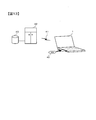
上述した実施の形態では、PC制御装置10が各処理を実行するためのプログラムがPC制御装置10のメモリに格納されている場合について説明した。しかしながら、PC1に対するプログラムのローディングは、図6に示すように、プログラムを格納したCD-ROMなどの記憶媒体40をPC1にセットして行ってもよいし、ネットワークなどの通信回線41を経由する方法でPC1へローディングしてもよい。通信回線41を経由する場合は、通信回線41に接続されたサーバー(コンピュータ)42のハードディスク装置43などにプログラムを格納しておき、プログラムを信号としてPC1に提供する。プログラムは、記憶媒体40や通信回線41を介する提供など、種々の形態のコンピュータプログラム製品として供給することができる。
上述した実施の形態では、カラーの透過原稿(ポジフィルム)の見えを再現する例について説明したが、モノクロの透過原稿の見えを再現する場合に本発明を適用してもよい。
上述した第1、第3、第4、第6の実施の形態では、RAWデータを、デバイス依存の画像データ(ディスプレイに依存するRGBデータ)に変換して出力する例について説明したが、デバイス非依存の画像データに変換して出力するようにしてもよい。
上述した第2、第5の実施の形態では、RAWデータを、デバイス非依存の色データ(L*a*b*値)に変換するLUTを生成する例について説明したが、デバイス依存の色データに変換するLUTを生成するようにしてもよい。
PC1のPC制御装置10が、コンピュータプログラムに従って、デジタルカメラ2からRAWデータを入力し、上述した図5のステップS1~S3までの処理を行い、濃度パラメータC、M、Yを画素ごとに算出し、各画素の濃度パラメータC、M、Yを記録媒体に記録する処理を実行するようにしてもよい。そして、別のPCのPC制御装置が当該記録媒体から濃度パラメータC、M、Yを読み出して、上述した図5のステップS4~S7の処理を行うことで、デジタルカメラ2の撮影画像データをポジフィルム調の画像に変換するようにしてもよい。
PC1のPC制御装置10が、コンピュータプログラムに従って、濃度パラメータC、M、Yを入力して、デバイス依存の色データ(ディスプレイRGBなど)またはデバイス非依存の色データ(L*a*b*値など)を出力するLUTを生成する処理を実行するようにしてもよい。この場合のPC制御装置10は、まず、このLUTの入力値(濃度パラメータC、M、Y)を生成する。入力値は、例えば、濃度パラメータC、M、Yの各々のデータレンジを、複数段階で等間隔に区切った格子点とする。そして、PC制御装置10は、生成した各入力値(濃度パラメータC、M、Y)において、上述した図5のステップS4~S7の処理を用いて、LUTの出力値である色データ(例えばディスプレイRGB)を求める。PC制御装置10は、各入力値(濃度パラメータC、M、Y)とこれに対する出力値(色データ)のセットをLUTとして生成して、記憶媒体12に記憶させる。
上述した実施の形態では、あらかじめ図4に示したような、ポジフィルムのシアン、マゼンタ、イエローの各層の分光濃度特性の測定値を準備し、シアン、マゼンタ、イエローの各層の分光濃度と濃度パラメータC,M,Yとを対応付けておく。また、濃度パラメータC,M,YとRAWデータとの対応関係(濃度変換マトリクス)を色パッチの撮影データなどから求めておく。撮像画像をポジフィルム調に変換する際には、上記のようにあらかじめ求めておいた対応関係(濃度変換マトリクス)を用いて、変換対象の撮像画像のRAWデータを濃度パラメータC,M,Yに変換する。そして、変換した濃度パラメータC,M,Yに対応する分光濃度特性から、三刺激値XYZを算出するようにした。このように、上述した実施形態では、分光濃度特性をベースとした画像変換によって、よりポジフィルムの色調に近い画像再現を可能とした。しかしながら、分光濃度特性をベースとした画像変換だけでなく、分光透過率特性をベースとした画像変換によっても、ポジフィルムの色調に近い画像再現を行うことができる。
T(λ)=Tc(λ)・Tm(λ)・Ty(λ)・Tb(λ) …(15)
X=∫{I(λ)・T(λ)・x(λ)}dλ …(16)
Y=∫{I(λ)・T(λ)・y(λ)}dλ …(17)
Z=∫{I(λ)・T(λ)・z(λ)}dλ …(18)
日本国特許出願2012年第192911号(2012年9月3日出願)
Claims (21)
- RAWデータの各色の画素値を、所定の分光特性に対応する値に変換するRAWデータ変換部と、
前記RAWデータ変換部で変換された前記分光特性に対応する値を、所定の出力画像データに変換する出力画像変換部と、
を備えるデジタルカメラ。 - 請求項1に記載のデジタルカメラにおいて、
前記所定の分光特性とは、透過原稿における各色素の分光特性であるデジタルカメラ。 - 請求項2に記載のデジタルカメラにおいて、
前記透過原稿は、写真フィルムであるデジタルカメラ。 - RAWデータの各色の画素値を、所定の分光特性に対応する値に変換するRAWデータ変換ステップと、
前記RAWデータ変換ステップで変換された前記分光特性に対応する値を、所定の出力画像データに変換する出力画像変換ステップと、
を有する情報処理方法。 - 請求項4に記載の情報処理方法において、
前記RAWデータ変換ステップでは、前記RAWデータの各色の画素値に対して対数変換を施すことにより対数変換値を出力し、前記対数変換値を透過原稿における各色素の濃度を示す濃度パラメータに変換し、
前記出力画像変換ステップでは、前記RAWデータ変換ステップで変換された濃度パラメータを、前記所定の出力画像データに変換する情報処理方法。 - 請求項5に記載の情報処理方法において、
前記出力画像変換ステップでは、前記濃度パラメータに対応する、前記透過原稿の分光濃度特性を算出し、前記透過原稿の分光濃度特性に基づいて、前記出力画像データを算出する情報処理方法。 - 請求項4~6のいずれか一項に記載の情報処理方法において、
前記出力画像データは、デバイス依存の画像データ、またはデバイス非依存の画像データである情報処理方法。 - 請求項5または6に記載の情報処理方法において、
前記RAWデータ変換ステップでは、前記対数変換値を、所定の変換情報を用いて前記濃度パラメータに変換し、
前記変換情報は、色パッチをデジタルカメラにより撮影した撮影データと当該色パッチを撮影した前記透過原稿を測色した測色データとに基づいて生成される情報処理方法。 - デジタルカメラにより撮像されたRAWデータを入力して所定の色データに変換するためのルックアップテーブルを生成する情報処理方法であって、
前記ルックアップテーブルの入力値に対して対数変換を施すことにより、対数変換値を出力する対数変換ステップと、
前記対数変換ステップで出力された対数変換値を、透過原稿における各色素の濃度を示す濃度パラメータに変換する濃度パラメータ変換ステップと、
前記濃度パラメータ変換ステップで変換された濃度パラメータを、デバイス依存またはデバイス非依存の色データに変換する色データ変換ステップと、
前記色データ変換ステップで変換された前記色データを前記ルックアップテーブルの出力値として前記ルックアップテーブルを生成するルックアップテーブル生成ステップと、
を有する情報処理方法。 - 請求項1に記載のデジタルカメラにおいて、
前記RAWデータ変換部は、前記RAWデータの各色の画素値に対して対数変換を施すことにより対数変換値を出力し、前記対数変換値を透過原稿における各色素の濃度を示す濃度パラメータに変換し、
前記出力画像変換部は、前記RAWデータ変換部で変換された濃度パラメータを、所定の出力画像データに変換するデジタルカメラ。 - 被写体像を撮像する撮像部と、
前記撮像部により撮像されたRAWデータに対して対数変換を施すことにより、対数変換値を出力する対数変換部と、
前記対数変換部で出力された対数変換値を、透過原稿における各色素の濃度を示す濃度パラメータに変換する濃度パラメータ変換部と、
前記濃度パラメータ変換部で変換された濃度パラメータを記録媒体に記録する記録制御部と、
を備えるデジタルカメラ。 - デジタルカメラにより撮像されたRAWデータを入力するRAWデータ入力ステップと、
前記RAWデータ入力ステップで入力されたRAWデータに対して対数変換を施すことにより、対数変換値を出力する対数変換ステップと、
前記対数変換ステップで出力された対数変換値を、透過原稿における各色素の濃度を示す濃度パラメータに変換する濃度パラメータ変換ステップと、
前記濃度パラメータ変換ステップで変換された濃度パラメータを記録媒体に記録する記録ステップと、
を有する情報処理方法。 - 透過原稿における各色素の濃度を示す濃度パラメータを入力する濃度パラメータ入力ステップと、
前記濃度パラメータ入力ステップで入力された濃度パラメータに対応する、前記透過原稿の分光濃度特性を算出する分光濃度特性算出ステップと、
前記分光濃度特性算出ステップで算出された前記透過原稿の分光濃度特性に基づいて、所定の出力画像データを算出する出力画像算出ステップと、
を有する情報処理方法。 - 透過原稿における各色素の濃度を示す濃度パラメータを入力して所定の色データに変換するためのルックアップテーブルを生成する情報処理方法であって、
前記濃度パラメータを入力する濃度パラメータ入力ステップと、
前記濃度パラメータ入力ステップで入力された濃度パラメータに対応する、前記透過原稿の分光濃度特性を算出する分光濃度特性算出ステップと、
前記分光濃度特性算出ステップで算出された前記透過原稿の分光濃度特性を、デバイス依存またはデバイス非依存の色データに変換する色データ変換ステップと、
前記色データ変換ステップで変換された前記色データを前記ルックアップテーブルの出力値として前記ルックアップテーブルを生成するルックアップテーブル生成ステップと、
を有する情報処理方法。 - 被写体像を撮像する撮像部と、
前記撮像部により撮像されたRAWデータに対して対数変換を施すことにより出力される対数変換値を、透過原稿における各色素の濃度を示す濃度パラメータに変換するための変換パラメータを記憶する記憶部と、
前記撮像部により撮像されたRAWデータと前記変換パラメータとを対応づけて記録媒体に記録する記録制御部と、
を備えるデジタルカメラ。 - 請求項5に記載の情報処理方法において、
前記RAWデータ変換ステップでは、請求項15に記載のデジタルカメラにより前記記録媒体に記録されたRAWデータの各色の画素値に対して対数変換を施すことにより対数変換値を出力し、前記対数変換値を、前記変換パラメータを用いて前記濃度パラメータに変換する情報処理方法。 - 請求項9に記載の情報処理方法において、
請求項15に記載のデジタルカメラにより前記記録媒体に記録された前記変換パラメータを入力する変換パラメータ入力ステップをさらに有し、
前記濃度パラメータ変換ステップでは、前記対数変換ステップで出力された対数変換値を、前記変換パラメータ入力ステップで入力された前記変換パラメータを用いて前記濃度パラメータに変換する情報処理方法。 - 請求項9または17に記載の情報処理方法において、さらに、
前記デジタルカメラにより撮像されたRAWデータを入力するRAWデータ入力ステップと、
前記RAWデータ入力ステップにより入力されたRAWデータを、前記ルックアップテーブル生成ステップで生成したルックアップテーブルを用いて変換する画像変換ステップと、
を有する情報処理方法。 - 請求項4に記載の情報処理方法において、
前記RAWデータ変換ステップでは、前記RAWデータの各色の画素値を、透過原稿における各色素の透過率を示す透過率パラメータに変換し、
前記出力画像変換ステップでは、前記RAWデータ変換ステップで変換された前記透過率パラメータを、前記所定の出力画像データに変換する情報処理方法。 - 請求項1に記載のデジタルカメラにおいて、
前記RAWデータ変換部は、前記RAWデータの各色の画素値を、透過原稿における各色素の透過率を示す透過率パラメータに変換し、
前記出力画像変換部は、前記RAWデータ変換部で変換された前記透過率パラメータを、前記所定の出力画像データに変換するデジタルカメラ。 - 請求項4~9、12~14、16~19のいずれか一項に記載の情報処理方法をコンピュータに実行させるコンピュータプログラム。
Priority Applications (2)
| Application Number | Priority Date | Filing Date | Title |
|---|---|---|---|
| US14/425,461 US9609235B2 (en) | 2012-09-03 | 2013-09-03 | Digital camera, information processing method, and computer program |
| JP2014533163A JP6264288B2 (ja) | 2012-09-03 | 2013-09-03 | 画像処理装置および画像処理方法 |
Applications Claiming Priority (2)
| Application Number | Priority Date | Filing Date | Title |
|---|---|---|---|
| JP2012192911 | 2012-09-03 | ||
| JP2012-192911 | 2012-09-03 |
Publications (1)
| Publication Number | Publication Date |
|---|---|
| WO2014034945A1 true WO2014034945A1 (ja) | 2014-03-06 |
Family
ID=50183742
Family Applications (1)
| Application Number | Title | Priority Date | Filing Date |
|---|---|---|---|
| PCT/JP2013/073664 Ceased WO2014034945A1 (ja) | 2012-09-03 | 2013-09-03 | デジタルカメラ、情報処理方法およびコンピュータプログラム |
Country Status (3)
| Country | Link |
|---|---|
| US (1) | US9609235B2 (ja) |
| JP (2) | JP6264288B2 (ja) |
| WO (1) | WO2014034945A1 (ja) |
Families Citing this family (2)
| Publication number | Priority date | Publication date | Assignee | Title |
|---|---|---|---|---|
| US8908081B2 (en) | 2010-09-09 | 2014-12-09 | Red.Com, Inc. | Optical filter opacity control for reducing temporal aliasing in motion picture capture |
| EP2984520B1 (en) * | 2013-04-05 | 2018-11-28 | Red.Com, Llc | Optical filtering for cameras |
Citations (4)
| Publication number | Priority date | Publication date | Assignee | Title |
|---|---|---|---|---|
| JPH05260500A (ja) * | 1991-06-05 | 1993-10-08 | Sony Corp Of America | デジタルカラー補正方式 |
| JP2001285889A (ja) * | 2000-02-18 | 2001-10-12 | Eastman Kodak Co | 好まれるカラーマッピングを伴なうシーンのカラー画像再生 |
| JP2001346218A (ja) * | 2000-03-27 | 2001-12-14 | Nikon Corp | 画像処理装置及び電子カメラ |
| JP2011024202A (ja) * | 2009-06-18 | 2011-02-03 | Victor Co Of Japan Ltd | 色変換装置、色変換方法、および画像表示システム |
Family Cites Families (11)
| Publication number | Priority date | Publication date | Assignee | Title |
|---|---|---|---|---|
| US5646750A (en) | 1991-06-05 | 1997-07-08 | Sony Corporation | Method and apparatus for compressing video in a manner characteristic of photographic film |
| JP3803441B2 (ja) * | 1996-11-29 | 2006-08-02 | 富士写真フイルム株式会社 | 色変換方法 |
| US6278533B1 (en) * | 1996-11-29 | 2001-08-21 | Fuji Photo Film Co., Ltd. | Method of processing image signal |
| JP2001194238A (ja) * | 2000-01-13 | 2001-07-19 | Dainippon Printing Co Ltd | 色変換テーブル作成方法および作成装置 |
| US7081918B2 (en) * | 2000-04-28 | 2006-07-25 | Fuji Photo Film Co., Ltd. | Image processing method, image processing apparatus and recording medium storing program therefor |
| JP2002190955A (ja) * | 2000-12-21 | 2002-07-05 | Canon Inc | 画像処理装置、画像処理システム、画像処理方法、及び記憶媒体 |
| TW559737B (en) * | 2001-11-02 | 2003-11-01 | Ind Tech Res Inst | Color conversion method for preference color |
| JP2005039425A (ja) * | 2003-07-17 | 2005-02-10 | Nikon Corp | 色再現範囲認識方法及び装置 |
| JP2005117524A (ja) * | 2003-10-10 | 2005-04-28 | Canon Inc | 画像処理システム |
| TW200945885A (en) * | 2008-04-25 | 2009-11-01 | Altek Corp | Digital image processing method for correcting shaking blur |
| JP2012524452A (ja) * | 2009-04-15 | 2012-10-11 | エレクトロニクス アンド テレコミュニケーションズ リサーチ インスチチュート | 感覚効果のためのメタデータ提供方法及び装置、感覚効果のためのメタデータが記録されたコンピュータ読み取り可能な記録媒体、感覚再生方法及び装置 |
-
2013
- 2013-09-03 US US14/425,461 patent/US9609235B2/en active Active
- 2013-09-03 WO PCT/JP2013/073664 patent/WO2014034945A1/ja not_active Ceased
- 2013-09-03 JP JP2014533163A patent/JP6264288B2/ja active Active
-
2017
- 2017-12-21 JP JP2017245578A patent/JP2018074607A/ja active Pending
Patent Citations (4)
| Publication number | Priority date | Publication date | Assignee | Title |
|---|---|---|---|---|
| JPH05260500A (ja) * | 1991-06-05 | 1993-10-08 | Sony Corp Of America | デジタルカラー補正方式 |
| JP2001285889A (ja) * | 2000-02-18 | 2001-10-12 | Eastman Kodak Co | 好まれるカラーマッピングを伴なうシーンのカラー画像再生 |
| JP2001346218A (ja) * | 2000-03-27 | 2001-12-14 | Nikon Corp | 画像処理装置及び電子カメラ |
| JP2011024202A (ja) * | 2009-06-18 | 2011-02-03 | Victor Co Of Japan Ltd | 色変換装置、色変換方法、および画像表示システム |
Also Published As
| Publication number | Publication date |
|---|---|
| US20150350564A1 (en) | 2015-12-03 |
| JPWO2014034945A1 (ja) | 2016-08-08 |
| JP2018074607A (ja) | 2018-05-10 |
| US9609235B2 (en) | 2017-03-28 |
| JP6264288B2 (ja) | 2018-01-24 |
Similar Documents
| Publication | Publication Date | Title |
|---|---|---|
| JP6455764B2 (ja) | 色補正パラメータ算出方法、色補正パラメータ算出装置および画像出力システム | |
| JP5195430B2 (ja) | 画像処理方法、画像処理プログラム、画像処理装置、カメラ | |
| JP5962169B2 (ja) | デジタルカメラ、色変換プログラムおよび記録制御プログラム | |
| JP4174703B2 (ja) | スペクトル・色再現システム | |
| JP2018098630A5 (ja) | ||
| JP5361643B2 (ja) | 画像処理装置および画像処理方法 | |
| JP2001285889A (ja) | 好まれるカラーマッピングを伴なうシーンのカラー画像再生 | |
| JP2001189875A (ja) | 画像捕捉の非線形性を補償するためのプロファイルの構成 | |
| JP2004312748A (ja) | 均衡化された最小の色誤差を含むデジタルカラー画像を作成する方法 | |
| JP6264288B2 (ja) | 画像処理装置および画像処理方法 | |
| JP2004145859A (ja) | 色管理による画像データの最適化 | |
| JP4874752B2 (ja) | デジタルカメラ | |
| US20060181721A1 (en) | Motion picture content preview | |
| JP2004159332A (ja) | プリンタ装置の出力画像の色彩管理方法 | |
| JP3912196B2 (ja) | 色変換表作成装置、色変換表作成方法、色変換表作成プログラムを記録した記録媒体、および、上記装置または方法によって作成された色変換表に基づいてプロファイルを作成するプロファイル作成装置 | |
| WO2023088188A1 (zh) | 图像的白平衡优化方法、装置和电子设备 | |
| JP2004064542A (ja) | 画像処理システム、装置及び方法 | |
| JP2003134536A (ja) | 色補正システム、色補正データ作成システム、およびプログラム | |
| JP2010124168A (ja) | 色変換マトリクス算出方法 | |
| Holm | Capture color analysis gamuts | |
| JP2015162871A (ja) | デジタルカメラ、画像処理プログラムおよびルックアップテーブル作成プログラム | |
| JP5104452B2 (ja) | 画像処理装置、画像処理方法および画像処理プログラム | |
| JP2015162870A (ja) | デジタルカメラおよび画像処理プログラム | |
| JP2002247396A (ja) | プリンターの色補正方法及びこの装置 | |
| JP2014230128A (ja) | コンピュータプログラムおよびデジタルカメラ |
Legal Events
| Date | Code | Title | Description |
|---|---|---|---|
| 121 | Ep: the epo has been informed by wipo that ep was designated in this application |
Ref document number: 13834017 Country of ref document: EP Kind code of ref document: A1 |
|
| ENP | Entry into the national phase |
Ref document number: 2014533163 Country of ref document: JP Kind code of ref document: A |
|
| NENP | Non-entry into the national phase |
Ref country code: DE |
|
| WWE | Wipo information: entry into national phase |
Ref document number: 14425461 Country of ref document: US |
|
| 122 | Ep: pct application non-entry in european phase |
Ref document number: 13834017 Country of ref document: EP Kind code of ref document: A1 |