WO2014034470A1 - 電池容器用表面処理鋼板、電池容器および電池 - Google Patents
電池容器用表面処理鋼板、電池容器および電池 Download PDFInfo
- Publication number
- WO2014034470A1 WO2014034470A1 PCT/JP2013/072140 JP2013072140W WO2014034470A1 WO 2014034470 A1 WO2014034470 A1 WO 2014034470A1 JP 2013072140 W JP2013072140 W JP 2013072140W WO 2014034470 A1 WO2014034470 A1 WO 2014034470A1
- Authority
- WO
- WIPO (PCT)
- Prior art keywords
- battery
- nickel
- iron
- steel sheet
- battery container
- Prior art date
- Legal status (The legal status is an assumption and is not a legal conclusion. Google has not performed a legal analysis and makes no representation as to the accuracy of the status listed.)
- Ceased
Links
Images
Classifications
-
- C—CHEMISTRY; METALLURGY
- C25—ELECTROLYTIC OR ELECTROPHORETIC PROCESSES; APPARATUS THEREFOR
- C25D—PROCESSES FOR THE ELECTROLYTIC OR ELECTROPHORETIC PRODUCTION OF COATINGS; ELECTROFORMING; APPARATUS THEREFOR
- C25D5/00—Electroplating characterised by the process; Pretreatment or after-treatment of workpieces
- C25D5/48—After-treatment of electroplated surfaces
- C25D5/50—After-treatment of electroplated surfaces by heat-treatment
-
- C—CHEMISTRY; METALLURGY
- C23—COATING METALLIC MATERIAL; COATING MATERIAL WITH METALLIC MATERIAL; CHEMICAL SURFACE TREATMENT; DIFFUSION TREATMENT OF METALLIC MATERIAL; COATING BY VACUUM EVAPORATION, BY SPUTTERING, BY ION IMPLANTATION OR BY CHEMICAL VAPOUR DEPOSITION, IN GENERAL; INHIBITING CORROSION OF METALLIC MATERIAL OR INCRUSTATION IN GENERAL
- C23C—COATING METALLIC MATERIAL; COATING MATERIAL WITH METALLIC MATERIAL; SURFACE TREATMENT OF METALLIC MATERIAL BY DIFFUSION INTO THE SURFACE, BY CHEMICAL CONVERSION OR SUBSTITUTION; COATING BY VACUUM EVAPORATION, BY SPUTTERING, BY ION IMPLANTATION OR BY CHEMICAL VAPOUR DEPOSITION, IN GENERAL
- C23C10/00—Solid state diffusion of only metal elements or silicon into metallic material surfaces
- C23C10/28—Solid state diffusion of only metal elements or silicon into metallic material surfaces using solids, e.g. powders, pastes
-
- C—CHEMISTRY; METALLURGY
- C23—COATING METALLIC MATERIAL; COATING MATERIAL WITH METALLIC MATERIAL; CHEMICAL SURFACE TREATMENT; DIFFUSION TREATMENT OF METALLIC MATERIAL; COATING BY VACUUM EVAPORATION, BY SPUTTERING, BY ION IMPLANTATION OR BY CHEMICAL VAPOUR DEPOSITION, IN GENERAL; INHIBITING CORROSION OF METALLIC MATERIAL OR INCRUSTATION IN GENERAL
- C23F—NON-MECHANICAL REMOVAL OF METALLIC MATERIAL FROM SURFACE; INHIBITING CORROSION OF METALLIC MATERIAL OR INCRUSTATION IN GENERAL; MULTI-STEP PROCESSES FOR SURFACE TREATMENT OF METALLIC MATERIAL INVOLVING AT LEAST ONE PROCESS PROVIDED FOR IN CLASS C23 AND AT LEAST ONE PROCESS COVERED BY SUBCLASS C21D OR C22F OR CLASS C25
- C23F17/00—Multi-step processes for surface treatment of metallic material involving at least one process provided for in class C23 and at least one process covered by subclass C21D or C22F or class C25
-
- C—CHEMISTRY; METALLURGY
- C25—ELECTROLYTIC OR ELECTROPHORETIC PROCESSES; APPARATUS THEREFOR
- C25D—PROCESSES FOR THE ELECTROLYTIC OR ELECTROPHORETIC PRODUCTION OF COATINGS; ELECTROFORMING; APPARATUS THEREFOR
- C25D3/00—Electroplating: Baths therefor
- C25D3/02—Electroplating: Baths therefor from solutions
- C25D3/12—Electroplating: Baths therefor from solutions of nickel or cobalt
-
- C—CHEMISTRY; METALLURGY
- C25—ELECTROLYTIC OR ELECTROPHORETIC PROCESSES; APPARATUS THEREFOR
- C25D—PROCESSES FOR THE ELECTROLYTIC OR ELECTROPHORETIC PRODUCTION OF COATINGS; ELECTROFORMING; APPARATUS THEREFOR
- C25D7/00—Electroplating characterised by the article coated
- C25D7/06—Wires; Strips; Foils
- C25D7/0614—Strips or foils
-
- H—ELECTRICITY
- H01—ELECTRIC ELEMENTS
- H01M—PROCESSES OR MEANS, e.g. BATTERIES, FOR THE DIRECT CONVERSION OF CHEMICAL ENERGY INTO ELECTRICAL ENERGY
- H01M50/00—Constructional details or processes of manufacture of the non-active parts of electrochemical cells other than fuel cells, e.g. hybrid cells
- H01M50/10—Primary casings; Jackets or wrappings
- H01M50/102—Primary casings; Jackets or wrappings characterised by their shape or physical structure
- H01M50/107—Primary casings; Jackets or wrappings characterised by their shape or physical structure having curved cross-section, e.g. round or elliptic
-
- H—ELECTRICITY
- H01—ELECTRIC ELEMENTS
- H01M—PROCESSES OR MEANS, e.g. BATTERIES, FOR THE DIRECT CONVERSION OF CHEMICAL ENERGY INTO ELECTRICAL ENERGY
- H01M50/00—Constructional details or processes of manufacture of the non-active parts of electrochemical cells other than fuel cells, e.g. hybrid cells
- H01M50/10—Primary casings; Jackets or wrappings
- H01M50/116—Primary casings; Jackets or wrappings characterised by the material
-
- H—ELECTRICITY
- H01—ELECTRIC ELEMENTS
- H01M—PROCESSES OR MEANS, e.g. BATTERIES, FOR THE DIRECT CONVERSION OF CHEMICAL ENERGY INTO ELECTRICAL ENERGY
- H01M50/00—Constructional details or processes of manufacture of the non-active parts of electrochemical cells other than fuel cells, e.g. hybrid cells
- H01M50/10—Primary casings; Jackets or wrappings
- H01M50/116—Primary casings; Jackets or wrappings characterised by the material
- H01M50/117—Inorganic material
- H01M50/119—Metals
-
- H—ELECTRICITY
- H01—ELECTRIC ELEMENTS
- H01M—PROCESSES OR MEANS, e.g. BATTERIES, FOR THE DIRECT CONVERSION OF CHEMICAL ENERGY INTO ELECTRICAL ENERGY
- H01M50/00—Constructional details or processes of manufacture of the non-active parts of electrochemical cells other than fuel cells, e.g. hybrid cells
- H01M50/10—Primary casings; Jackets or wrappings
- H01M50/116—Primary casings; Jackets or wrappings characterised by the material
- H01M50/124—Primary casings; Jackets or wrappings characterised by the material having a layered structure
-
- H—ELECTRICITY
- H01—ELECTRIC ELEMENTS
- H01M—PROCESSES OR MEANS, e.g. BATTERIES, FOR THE DIRECT CONVERSION OF CHEMICAL ENERGY INTO ELECTRICAL ENERGY
- H01M50/00—Constructional details or processes of manufacture of the non-active parts of electrochemical cells other than fuel cells, e.g. hybrid cells
- H01M50/10—Primary casings; Jackets or wrappings
- H01M50/131—Primary casings; Jackets or wrappings characterised by physical properties, e.g. gas permeability, size or heat resistance
- H01M50/133—Thickness
-
- H—ELECTRICITY
- H01—ELECTRIC ELEMENTS
- H01M—PROCESSES OR MEANS, e.g. BATTERIES, FOR THE DIRECT CONVERSION OF CHEMICAL ENERGY INTO ELECTRICAL ENERGY
- H01M10/00—Secondary cells; Manufacture thereof
- H01M10/05—Accumulators with non-aqueous electrolyte
-
- Y—GENERAL TAGGING OF NEW TECHNOLOGICAL DEVELOPMENTS; GENERAL TAGGING OF CROSS-SECTIONAL TECHNOLOGIES SPANNING OVER SEVERAL SECTIONS OF THE IPC; TECHNICAL SUBJECTS COVERED BY FORMER USPC CROSS-REFERENCE ART COLLECTIONS [XRACs] AND DIGESTS
- Y02—TECHNOLOGIES OR APPLICATIONS FOR MITIGATION OR ADAPTATION AGAINST CLIMATE CHANGE
- Y02E—REDUCTION OF GREENHOUSE GAS [GHG] EMISSIONS, RELATED TO ENERGY GENERATION, TRANSMISSION OR DISTRIBUTION
- Y02E60/00—Enabling technologies; Technologies with a potential or indirect contribution to GHG emissions mitigation
- Y02E60/10—Energy storage using batteries
-
- Y—GENERAL TAGGING OF NEW TECHNOLOGICAL DEVELOPMENTS; GENERAL TAGGING OF CROSS-SECTIONAL TECHNOLOGIES SPANNING OVER SEVERAL SECTIONS OF THE IPC; TECHNICAL SUBJECTS COVERED BY FORMER USPC CROSS-REFERENCE ART COLLECTIONS [XRACs] AND DIGESTS
- Y10—TECHNICAL SUBJECTS COVERED BY FORMER USPC
- Y10T—TECHNICAL SUBJECTS COVERED BY FORMER US CLASSIFICATION
- Y10T428/00—Stock material or miscellaneous articles
- Y10T428/12—All metal or with adjacent metals
- Y10T428/12431—Foil or filament smaller than 6 mils
- Y10T428/12438—Composite
Definitions
- the present invention relates to a surface-treated steel sheet for battery containers, a battery container using the surface-treated steel sheet for battery containers, and a battery using the battery container.
- lithium-ion batteries which are secondary batteries, are frequently used as operating power sources used in portable electronic devices such as video cameras, electronic notebooks, and notebook computers.
- Such batteries are required to be smaller, lighter, and larger in capacity with higher performance of mounted devices, and battery containers filled with power generation elements made of a positive electrode active material or a negative electrode active material are also available.
- it is formed into a shape suitable for the application by drawing, ironing, DI or DTR molding.
- Patent Document 1 discloses a battery container in which a nickel plating layer is formed on the inner surface of a battery container as a battery container based on iron of a battery using a non-aqueous electrolyte. Yes.
- the present inventors have conducted a thermal diffusion treatment after forming a nickel plating layer on the steel sheet, so that the Ni / Fe molar ratio of the outermost layer is 7.5 or less.
- the inventors have found that the above object can be achieved by forming an iron-nickel diffusion layer having a thickness of 0.6 ⁇ m or more, and have completed the present invention.
- a surface-treated steel sheet for a battery container for forming a battery container for a battery that uses a non-aqueous electrolyte as an electrolytic solution, and at least a surface on the inner surface side of the battery container is nickel on the surface of the steel sheet. It has an iron-nickel diffusion layer formed by performing thermal diffusion treatment after forming the plating layer, and the ratio of Ni and Fe in the outermost layer of the iron-nickel diffusion layer is the molar ratio of Ni / Fe. And a surface-treated steel sheet for battery containers, wherein the iron-nickel diffusion layer has a thickness of 0.6 ⁇ m or more.
- the thickness of the Ni plating before the thermal diffusion treatment is preferably 1.0 ⁇ m or less.
- molding one of the said surface-treated steel sheets for battery containers is provided.
- the battery which uses the said battery container is provided.
- the present invention when used as a battery container of a battery using a non-aqueous electrolyte, elution of iron and nickel into the non-aqueous electrolyte can be suppressed, thereby generating pitting corrosion and liquid leakage. It is possible to provide a surface-treated steel sheet for a battery container that can effectively prevent deterioration of battery characteristics, and a battery container and a battery obtained using the surface-treated steel sheet for battery container.
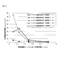
- FIG. 1 is a diagram showing the results of measuring the average corrosion current density on the inner surface side of the center portion of the can body of the battery container using the surface-treated steel sheets according to the examples and comparative examples of the present invention.
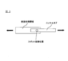
- FIG. 2 is a diagram for explaining a method for evaluating spot weldability of the surface-treated steel sheets according to Examples and Comparative Examples of the present invention.
- the surface-treated steel sheet for a battery container according to the present invention is a surface-treated steel sheet for a battery container for forming a battery container for a battery using a non-aqueous electrolyte as an electrolyte, and is at least the inner surface side of the battery container.
- the nickel plating layer After the nickel plating layer is formed on the surface, it has an iron-nickel diffusion layer formed by performing a thermal diffusion treatment, and the ratio of Ni and Fe in the outermost layer of the iron-nickel diffusion layer is Ni / Fe The molar ratio is 7.5 or less, and the thickness of the iron-nickel diffusion layer is 0.6 ⁇ m or more.
- any steel sheet may be used as long as it is excellent in drawing workability, drawing ironing workability, workability by drawing and bending back work (DTR).
- DTR drawing and bending back work
- a low carbon aluminum killed steel carbon content 0.01 to 0.15 wt% or an ultra low carbon steel having a carbon content of 0.003 wt% or less can be used.
- these steel hot-rolled plates are pickled to remove the surface scale (oxide film), cold-rolled, and then the electrolytically washed rolling oil, or after the electrolytic cleaning,
- a substrate that has been annealed and temper-rolled is used as a substrate.
- the annealing may be either continuous annealing or box annealing, and is not particularly limited.
- the surface-treated steel sheet for battery containers of the present invention includes an iron-nickel diffusion layer on the steel sheet.
- the iron-nickel diffusion layer is formed by forming a nickel plating layer on the steel plate, and then performing heat diffusion treatment on the steel plate on which the nickel plating layer is formed, thereby forming the iron constituting the steel plate and the nickel plating. It is a layer formed by thermally diffusing nickel constituting the layer, and the ratio of Ni and Fe in the outermost layer is 7.5 or less in terms of Ni / Fe molar ratio, and the thickness is 0.00. It is a layer which is 6 ⁇ m or more.
- an iron-nickel diffusion layer is formed by thermal diffusion, and for the formed iron-nickel diffusion layer, the Ni / Fe molar ratio and thickness in the outermost layer are within the above ranges, so that the non-aqueous electrolyte solution When used as a battery container for a battery that uses, the elution of iron and nickel into the non-aqueous electrolyte can be suppressed, thereby effectively preventing the occurrence of pitting corrosion, liquid leakage, and deterioration of battery characteristics.
- a surface-treated steel sheet for battery containers can be obtained.
- the Ni / Fe molar ratio in the outermost layer of the iron-nickel diffusion layer is 7.5 or less, preferably 7.0 or less, more preferably 6. 5 or less. If the molar ratio of Ni / Fe is too high, the proportion of nickel in the iron-nickel diffusion layer will increase, and when used as a battery container for a battery using a non-aqueous electrolyte due to the influence of nickel, an electrode or can While weldability with a lid or the like is deteriorated, nickel is eluted into the nonaqueous electrolytic solution constituting the battery, and as a result, the battery characteristics may be deteriorated.
- the lower limit of the Ni / Fe molar ratio is usually 0 from the point that it is necessary to appropriately contain nickel in the iron-nickel diffusion layer in order to suppress elution of iron in the non-aqueous electrolyte. .15 or more, preferably 0.30 or more.
- the molar ratio of Ni / Fe can be measured, for example, by the following method. That is, first, the surface of the iron-nickel diffusion layer is measured using a scanning Auger electron spectrometer (AES), and the atomic percentages of Ni and Fe on the surface of the iron-nickel diffusion layer are calculated. Then, the surface of the iron-nickel diffusion layer was measured with a scanning Auger electron spectrometer at five locations, and the obtained results were averaged to obtain a Ni / Fe molar ratio (Ni atomic% / (Atomic% of Fe) can be calculated.
- AES scanning Auger electron spectrometer
- the peak at 820 to 850 eV is the Ni peak
- the peak at 570 to 600 eV is the Fe peak
- Ni is the atomic% of Ni and Fe is measured with the total of Fe as 100 atomic%.
- the thickness of the iron-nickel diffusion layer is 0.6 ⁇ m in addition to the Ni / Fe molar ratio in the outermost layer of the iron-nickel diffusion layer being in the above range. It is above, Preferably it is 0.8 micrometer or more. If the thickness of the iron-nickel diffusion layer is too thin, the effect of suppressing elution of iron and nickel in the non-aqueous electrolyte cannot be obtained sufficiently. In the present invention, when the Ni / Fe molar ratio in the outermost layer of the iron-nickel diffusion layer is in the above range, the thickness of the iron-nickel diffusion layer is in the above range, whereby the battery container is obtained. In addition, elution of iron and nickel into the non-aqueous electrolyte can be suppressed, and the occurrence of pitting corrosion, liquid leakage, and deterioration of battery characteristics can be effectively prevented.
- the thickness of the iron-nickel diffusion layer can be measured, for example, by the following method. That is, with respect to the surface-treated steel sheet for battery containers of the present invention, using a high-frequency glow discharge emission spectroscopic analyzer, the transition of the Ni intensity is measured in the depth direction of the iron-nickel diffusion layer. By detecting the depth until it no longer exists, the thickness of the iron-nickel diffusion layer can be determined.
- nickel exists in the area
- the Ni strength is measured in the depth direction for the surface-treated steel sheet for battery containers, and the Ni strength is less than 1/10 of the maximum value of the Ni strength starting from the measurement start time. It is possible to calculate the measurement time up to the point in time, and obtain the thickness of the iron-nickel diffusion layer based on the calculated measurement time.
- the surface-treated steel sheet for battery containers of the present invention is formed with the iron-nickel diffusion layer as described above.
- Such an iron-nickel diffusion layer can be formed, for example, by the following method.
- the nickel plating layer for forming the iron-nickel diffusion layer can be formed on the steel plate by using, for example, a nickel plating bath.
- a nickel plating bath a plating bath usually used in nickel plating, that is, a watt bath, a sulfamic acid bath, a borofluoride bath, a chloride bath, or the like can be used.
- the nickel plating layer uses a bath composition of nickel sulfate 200 to 350 g / L, nickel chloride 20 to 60 g / L, boric acid 10 to 50 g / L as a watt bath, pH 3 to 4.8, bath temperature 40 It can be formed under the conditions of a current density of 10 to 40 A / dm 2 (preferably 20 to 30 A / dm 2 ) at ⁇ 70 ° C.
- the nickel plating layer is formed on the surface of the steel plate that is at least the inner surface side of the battery container.
- the iron-nickel diffusion layer is formed by performing a thermal diffusion treatment on the steel plate on which the nickel plating layer is formed. To do.
- the thermal diffusion treatment may be either a continuous annealing method or a box annealing method, and is not particularly limited.
- the thermal diffusion treatment conditions may be appropriately selected according to the thickness of the nickel plating layer and the amount of adhesion.
- the heat treatment temperature 700 to 800 ° C.
- the heat treatment time 10 to 300 seconds are preferable.
- heat treatment temperature 450 to 600 ° C.
- heat treatment time 1 to 10 hours
- heat treatment atmosphere non-oxidizing atmosphere or reducing protective gas atmosphere It is preferable.
- the heat treatment atmosphere is a reducing protective gas atmosphere
- a protective gas composed of 75% hydrogen-25% nitrogen generated by an ammonia cracking method called hydrogen enriched annealing with good heat transfer is used as the protective gas. It is preferable to use it.
- the thickness of the nickel plating layer before performing the thermal diffusion process is preferably 1.0 ⁇ m or less (the amount of nickel is 8.9 g / m 2 or less).
- the thickness of the nickel plating layer is preferably 1.0 ⁇ m or less (the amount of nickel is 8.9 g / m 2 or less).
- the nickel plating layer before the thermal diffusion treatment is too thick, that is, if the thickness of the nickel plating layer before the thermal diffusion treatment is more than 1.0 ⁇ m (the amount of nickel is 8.9 g / m). 2 ), even if the thermal diffusion treatment is performed under the above-described conditions, the diffusion of iron into the nickel plating layer becomes insufficient, and a nickel-only layer in which iron is not diffused remains on the outermost surface. End up. In this case, due to the influence of nickel located on the outermost surface, there is a problem that the weldability deteriorates when the battery container is welded to the electrode or can lid, or the outermost surface in the non-aqueous electrolyte during actual use. There is a problem that the nickel located in the region is eluted and thereby the battery characteristics are deteriorated.
- iron is thermally diffused to the surface of the nickel plating layer having a thickness of over 1.0 ⁇ m (the amount of nickel is over 8.9 g / m 2 ).
- the thermal diffusion conditions it is necessary to set the thermal diffusion conditions at a higher temperature and for a longer time (for example, higher and longer than the thermal diffusion treatment conditions described above). In this case, excessive heat is applied to the steel sheet, which causes the following problems. That is, when the thermal diffusion treatment is performed by continuous annealing, the upper limit of the heat treatment time is limited due to the property that the continuous annealing is performed by being incorporated in a production line.
- box-type annealing a method of heating steel sheets in a coil state in a box-type annealing furnace is usually used, and as a result, the steel sheets in the coil state are heated for a long time, so that the steel sheets stick to each other. There is.
- the surface-treated steel sheet for battery containers according to the present invention has a nickel plating layer thickness before the thermal diffusion treatment within the above range so that the iron is thermally diffused to the surface of the nickel plating layer. Since the heat treatment temperature can be carried out under appropriate conditions, it is possible to effectively prevent the deterioration of the mechanical properties of the steel plates and the sticking between the steel plates.
- the lower limit of the thickness of the nickel plating layer before the thermal diffusion treatment is not particularly limited, but is usually 0.1 ⁇ m or more, preferably 0.2 ⁇ m or more.
- the battery container of the present invention is used to form a battery using a non-aqueous electrolyte, and the above-described surface-treated steel sheet for a battery container of the present invention has a Ni / Fe molar ratio and thickness in the outermost layer within the above range.
- the obtained iron-nickel diffusion layer is obtained by molding so as to be on the inner surface side of the battery container.
- the battery container of the present invention can be obtained by forming the above-described surface-treated steel sheet for battery containers of the present invention into a battery container shape by drawing, ironing, DI or DTR molding.
- the battery container of the present invention uses the above-described surface-treated steel sheet for battery containers of the present invention, it suppresses elution of iron and nickel into the non-aqueous electrolyte when used as a battery container. Therefore, it is possible to effectively prevent the occurrence of pitting corrosion, liquid leakage, and deterioration of battery characteristics.
- the surface-treated steel sheet for battery containers of the present invention is suitably used as a battery container such as a lithium ion battery in which a nonaqueous electrolytic solution is used as an electrolytic solution.
- a lithium ion battery using such a non-aqueous electrolyte can be manufactured as follows, for example, using the surface-treated steel sheet for battery containers of the present invention.
- a positive electrode obtained by applying a positive electrode mixture to a metal foil is prepared, and the prepared negative electrode and positive electrode are laminated via a separator to form an electrode current collector.
- the formed electrode current collector is housed in a battery container formed using the surface-treated steel sheet for a battery container of the present invention in a state impregnated with a non-aqueous electrolyte, and the negative electrode and the battery container are electrically connected. After the connection, the battery container is sealed. Thereby, the lithium ion battery using a non-aqueous electrolyte is manufactured using the surface-treated steel sheet for battery containers of the present invention.
- an organic electrolyte in which a supporting electrolyte is dissolved in an organic solvent is used.
- a lithium salt is used as the supporting electrolyte.
- the lithium salt is not particularly limited, LiPF 6, LiAsF 6, LiBF 4, LiSbF 6, LiAlCl 4, LiClO 4, CF 3 SO 3 Li, C 4 F 9 SO 3 Li, CF 3 COOLi, (CF 3 CO) 2 NLi, (CF 3 SO 2 ) 2 NLi, (C 2 F 5 SO 2 ) NLi, and the like.
- the organic solvent used for the non-aqueous electrolyte of the lithium ion battery is not particularly limited as long as it can dissolve the supporting electrolyte, but dimethyl carbonate (DMC), ethylene carbonate (EC), diethyl carbonate (DEC), Carbonates such as propylene carbonate (PC), butylene carbonate (BC), methyl ethyl carbonate (MEC) and vinylene carbonate (VC); esters such as ⁇ -butyrolactone and methyl formate; 1,2-dimethoxyethane (DME), Ethers such as tetrahydrofuran; sulfur-containing compounds such as sulfolane and dimethyl sulfoxide; and the like may be used alone or in combination of two or more.
- DMC dimethyl carbonate
- EC ethylene carbonate
- DEC diethyl carbonate
- Carbonates such as propylene carbonate (PC), butylene carbonate (BC), methyl ethyl carbonate (MEC) and vinylene carbon
- the battery container of the present invention is formed by using the above-described surface-treated steel sheet for a battery container of the present invention, even when such a non-aqueous electrolyte is used as the battery electrolyte, the kind of the organic solvent is used. Regardless of the combination, mixing ratio, type of lithium salt, and content, elution of iron and nickel from the inner surface side of the battery container to the non-aqueous electrolyte can be effectively suppressed.
- ⁇ Measurement of thickness of iron-nickel diffusion layer> Using a high-frequency glow discharge emission spectroscopic analyzer (manufactured by Rigaku Corporation, model number: System 3860T), the Ni intensity transition is measured from the surface of the surface-treated steel sheet in the depth direction, and the starting point of measurement is the starting point. The measurement time until the Ni strength became less than 1/10 of the maximum value of the Ni strength was calculated, and the thickness of the iron-nickel diffusion layer was determined based on the calculated measurement time. The thickness of the iron-nickel diffusion layer was measured only for Examples 1 to 8 and Comparative Examples 1 to 4 among Examples and Comparative Examples described later.
- Ni / Fe molar ratio in outermost layer First, using a scanning Auger electron spectroscopy analyzer (manufactured by JEOL Ltd., model number: JAMP-9500F), five locations on the surface of the surface-treated steel sheet were measured, and the atomic percentages of Ni and Fe at each location were calculated. . Next, from the calculation results at each location, an average value of Ni and Fe atomic% was calculated, and a Ni / Fe molar ratio (Ni atomic% / Fe atomic%) was obtained based on the calculated average value. . The molar ratio of Ni / Fe in the outermost layer was measured for all examples and comparative examples described later.
- spot weldability of the surface-treated steel sheet was evaluated using the surface-treated steel sheet and the nickel tab. Specifically, first, a nickel tab (thickness 0.1 mm, width 5 mm, length 40 mm) manufactured by rolling a pure nickel plate was prepared, and a portion 10 mm from the tip of the prepared nickel tab (FIG. 2). In the vicinity of the spot welding position shown in FIG. Next, the surface-treated steel sheet was processed into a width of 10 mm and a length of 40 mm. As shown in FIG. 2, the surface-treated steel sheet and the nickel tab were spot-welded at a load of 30 N and energization time: 0.01 seconds.
- the can body center part was cut out from the battery container obtained by shaping the surface-treated steel sheet and immersed in a non-aqueous electrolyte prepared in advance.
- a non-aqueous electrolyte LiPF 6 was added to a non-aqueous solvent in which ethylene carbonate (EC) and 1,2-dimethoxyethane (DME) were mixed at a volume ratio of 1: 1 so that the concentration would be 1M.
- the electrolyte solution used was used.
- the average corrosion current density thus obtained is a value indicating the current density flowing in the surface layer on the inner surface side of the battery container when immersed in a non-aqueous electrolyte and subjected to constant potential electrolysis, It can be determined whether or not an electrode reaction has occurred on the inner surface side of the battery container. Specifically, when the average corrosion current density exceeds 20 mA / dm 2 , an electrode reaction occurs on the inner surface side of the battery container, and iron or nickel is eluted from the inner surface side of the battery container into the nonaqueous electrolyte. Can be determined.
- Example 1 As a substrate, a steel sheet obtained by annealing a cold rolled sheet (thickness: 0.25 mm) of low carbon aluminum killed steel having the chemical composition shown below was prepared. C: 0.045 wt%, Mn: 0.23% wt, Si: 0.02 wt%, P: 0.012 wt%, S: 0.009 wt%, Al: 0.063 wt%, balance: Fe and inevitable impurities
- the steel plate on which the nickel plating layer was formed was subjected to thermal diffusion treatment at a temperature of 700 ° C. for 1 minute under a reducing atmosphere condition by continuous annealing, thereby forming an iron-nickel diffusion layer to obtain a surface-treated steel plate.
- the surface-treated steel sheet thus obtained was subjected to the measurement of the thickness of the iron-nickel diffusion layer, the measurement of the Ni / Fe molar ratio in the outermost layer, and the evaluation of spot weldability according to the method described above. It was. The results are shown in Tables 1 and 2.
- FIG. 1 is a graph showing the relationship between the thickness of the nickel plating layer before heat treatment and the average corrosion current density.
- the results of Examples 2 to 8 and Comparative Examples 1 to 4 described later are displayed in a line graph, and a line graph is displayed for each temperature condition subjected to thermal diffusion treatment. Different line types. Specifically, in FIG. 1, when the temperature condition of the thermal diffusion treatment is 700 ° C., it is displayed with a solid line, when it is 800 ° C., it is displayed with a broken line, and when it is 900 ° C., it is a one-dot chain line. Is displayed. Further, on the graph of FIG. 1, the results of Examples 1 to 8 are plotted with black markers, and the results of Comparative Examples 1 to 4 are plotted with white markers.
- Examples 2 to 4 The nickel plating layer before the heat treatment was formed in each thickness shown in Tables 1 and 2, and the temperature at the time of performing the thermal diffusion treatment was changed as shown in Tables 1 and 2 in the same manner as in Example 1.
- a surface-treated steel sheet and a battery container were prepared and evaluated in the same manner. The results are shown in Tables 1 and 2 and FIG.
- Examples 5 and 6 A surface-treated steel sheet is formed in the same manner as in Example 1 except that the nickel plating layer before heat treatment is formed in each thickness shown in Table 1 and the temperature at the time of performing the thermal diffusion treatment is changed as shown in Table 1. And the battery container was produced. Next, the surface-treated steel sheet and battery container obtained were measured for the thickness of the iron-nickel diffusion layer, the Ni / Fe molar ratio in the outermost layer, and the average corrosion current density according to the methods described above. It was. The results are shown in Table 1 and FIG.
- Examples 7 and 8 >> The nickel plating layer before the heat treatment was formed in each thickness shown in Tables 1 and 2, and the temperature at the time of performing the thermal diffusion treatment was changed as shown in Tables 1 and 2 in the same manner as in Example 1. A surface-treated steel sheet and a battery container were prepared and evaluated in the same manner. The results are shown in Tables 1 and 2 and FIG.
- Comparative Examples 1 to 4 A surface-treated steel sheet is formed in the same manner as in Example 1 except that the nickel plating layer before heat treatment is formed in each thickness shown in Table 1 and the temperature at the time of thermal diffusion treatment is changed as shown in Table 1. And the battery container was produced. Next, the surface-treated steel sheet and battery container obtained were measured for the thickness of the iron-nickel diffusion layer, the Ni / Fe molar ratio in the outermost layer, and the average corrosion current density according to the methods described above. It was. The results are shown in Table 1 and FIG.
- Comparative Examples 5 and 6 Surface treatment was carried out in the same manner as in Example 1 except that the nickel plating layer was formed in each thickness shown in Table 2 and then the thermal diffusion treatment was not performed (the iron-nickel diffusion layer was not formed). A steel plate and a battery container were prepared. Next, the obtained surface-treated steel sheet and battery container were measured for the Ni / Fe molar ratio in the outermost layer and evaluated for spot weldability according to the above-described method. The results are shown in Table 2.
- the molar ratio of Ni / Fe in the outermost layer of the iron-nickel diffusion layer is 7.5 or less, and the thickness of the iron-nickel diffusion layer is 0.6 ⁇ m or more.
- the values of average corrosion current density both become 6.5 mA / dm 2 the following values are 20 mA / dm 2 or less, the iron from the inner surface of the battery container to the non-aqueous electrolyte solution And nickel elution were effectively suppressed.
- Examples 1 to 4, 7, and 8 in which the spot weldability was evaluated the evaluation results of the spot weldability were good and the weldability was excellent.
- Comparative Examples 1 to 4 in which the thickness of the iron-nickel diffusion layer is less than 0.6 ⁇ m, the average corrosion current density value is 26.9 mA / dm 2 or more, both of which exceed 20 mA / dm 2 .
- the average corrosion current density value is 26.9 mA / dm 2 or more, both of which exceed 20 mA / dm 2 .
- iron and nickel were eluted from the inner surface of the battery container into the non-aqueous electrolyte.
- Comparative Examples 5 and 6 in which the Ni / Fe molar ratio on the outermost surface is not more than 7.5 without carrying out the thermal diffusion treatment, the result of the poor spot weldability evaluation results and poor weldability. It was.
Landscapes
- Chemical & Material Sciences (AREA)
- Chemical Kinetics & Catalysis (AREA)
- Electrochemistry (AREA)
- Engineering & Computer Science (AREA)
- Materials Engineering (AREA)
- Metallurgy (AREA)
- Organic Chemistry (AREA)
- General Chemical & Material Sciences (AREA)
- Mechanical Engineering (AREA)
- Inorganic Chemistry (AREA)
- Electroplating Methods And Accessories (AREA)
- Sealing Battery Cases Or Jackets (AREA)
Description
本発明は、電池容器用表面処理鋼板、該電池容器用表面処理鋼板を用いた電池容器、および該電池容器を用いた電池に関する。
近年、ビデオカメラ、電子手帳、ノートパソコンなどのポータブル電子機器に用いられる作動電源として二次電池であるリチウムイオン電池などが多用されている。このような電池は、搭載される機器の高性能化に伴い、小型化、軽量化、大容量化が求められており、正極活物質や負極活物質などからなる発電要素を充填する電池容器も電池の重要な構成要素としての性能を向上させるために、絞り、しごき、DIまたはDTR成形により、用途に合わせた形状に成形されている。
このような電池容器として、たとえば、特許文献1では、非水電解液を用いる電池の鉄を基材とした電池容器として、電池容器内面にニッケルめっき層を形成してなる電池容器が開示されている。
しかしながら、上記特許文献1に開示されている電池容器では、ニッケルめっき層が薄すぎると、ニッケルによる耐食性が低下することで、非水電解液へ鉄が溶解してしまい、鉄の溶解により生じた孔食の影響により液漏れが発生してしまうという課題がある。そのため、ニッケルめっき層を厚膜化する必要があるが、ニッケルめっき層を厚膜化すると、コスト的に不利になり、また、鉄とニッケルとの延展性の違いなどによりニッケルめっき層が鋼板から脱落してしまうという問題がある。さらに、ニッケルめっき層を厚膜化した場合であっても、用いる非水電解液の種類によっては、ニッケルが非水電解液中に溶解してしまい、電池特性が低下してしまうという問題もある。
本発明の目的は、非水電解液を用いる電池の電池容器として用いた際に、非水電解液中への鉄やニッケルの溶出を抑制することができ、孔食や液漏れの発生、電池特性の低下を有効に防止することができる電池容器用表面処理鋼板を提供することである。また、本発明は、このような電池容器用表面処理鋼板を用いて得られる電池容器および電池を提供することも目的とする。
本発明者等は、上記目的を達成すべく鋭意検討した結果、鋼板上にニッケルめっき層を形成した後に、熱拡散処理を行うことにより、最表層のNi/Feのモル比が7.5以下であり、かつ、厚みが0.6μm以上である鉄-ニッケル拡散層を形成することにより、上記目的を達成できることを見出し本発明を完成させるに至った。
すなわち、本発明によれば、電解液として非水電解液を用いる電池の電池容器を形成するための電池容器用表面処理鋼板であって、鋼板の、少なくとも電池容器の内面側となる面にニッケルめっき層を形成した後に、熱拡散処理を行うことにより形成された鉄-ニッケル拡散層を有し、前記鉄-ニッケル拡散層の最表層におけるNiとFeとの比率が、Ni/Feのモル比で7.5以下であり、かつ、前記鉄-ニッケル拡散層の厚みが0.6μm以上であることを特徴とする電池容器用表面処理鋼板が提供される。
本発明の電池容器用表面処理鋼板は、熱拡散処理を施す前における前記Niめっきの厚みが1.0μm以下であることが好ましい。
本発明によれば、上記いずれかの電池容器用表面処理鋼板を成形加工してなる電池容器が提供される。
また、本発明によれば、上記電池容器を用いてなる電池が提供される。
また、本発明によれば、上記電池容器を用いてなる電池が提供される。
本発明によれば、非水電解液を用いる電池の電池容器として用いた際に、非水電解液中への鉄やニッケルの溶出を抑制することができ、これにより孔食や液漏れの発生、電池特性の低下を有効に防止することができる電池容器用表面処理鋼板、ならびに該電池容器用表面処理鋼板を用いて得られる電池容器および電池を提供することができる。
以下、本発明の電池容器用表面処理鋼板について説明する。
本発明の電池容器用表面処理鋼板は、電解液として非水電解液を用いる電池の電池容器を形成するための電池容器用表面処理鋼板であって、鋼板の、少なくとも電池容器の内面側となる面にニッケルめっき層を形成した後に、熱拡散処理を行うことにより形成された鉄-ニッケル拡散層を有し、鉄-ニッケル拡散層の最表層におけるNiとFeとの比率が、Ni/Feのモル比で7.5以下であり、かつ、鉄-ニッケル拡散層の厚みが0.6μm以上であることを特徴とする。
本発明の電池容器用表面処理鋼板は、電解液として非水電解液を用いる電池の電池容器を形成するための電池容器用表面処理鋼板であって、鋼板の、少なくとも電池容器の内面側となる面にニッケルめっき層を形成した後に、熱拡散処理を行うことにより形成された鉄-ニッケル拡散層を有し、鉄-ニッケル拡散層の最表層におけるNiとFeとの比率が、Ni/Feのモル比で7.5以下であり、かつ、鉄-ニッケル拡散層の厚みが0.6μm以上であることを特徴とする。
<鋼板>
本発明の電池容器用表面処理鋼板の基板となる鋼板としては、絞り加工性、絞りしごき加工性、絞り加工と曲げ戻し加工による加工(DTR)の加工性に優れているものであればよく特に限定されないが、たとえば、低炭素アルミキルド鋼(炭素量0.01~0.15重量%)、または炭素量が0.003重量%以下の極低炭素鋼を用いることができる。
本発明の電池容器用表面処理鋼板の基板となる鋼板としては、絞り加工性、絞りしごき加工性、絞り加工と曲げ戻し加工による加工(DTR)の加工性に優れているものであればよく特に限定されないが、たとえば、低炭素アルミキルド鋼(炭素量0.01~0.15重量%)、または炭素量が0.003重量%以下の極低炭素鋼を用いることができる。
本発明においては、これらの鋼の熱間圧延板を酸洗して表面のスケール(酸化膜)を除去した後、冷間圧延し、次いで圧延油を電解洗浄したもの、あるいは前記電解洗浄後に、焼鈍、調質圧延したものを基板として用いる。この場合における、焼鈍は、連続焼鈍あるいは箱型焼鈍のいずれでもよく、特に限定されない。
<鉄-ニッケル拡散層>
本発明の電池容器用表面処理鋼板は、鋼板上に、鉄-ニッケル拡散層を備える。本発明においては、鉄-ニッケル拡散層は、鋼板上にニッケルめっき層を形成し、次いで、ニッケルめっき層を形成した鋼板について、熱拡散処理を行うことにより、鋼板を構成する鉄と、ニッケルめっき層を構成するニッケルとを熱拡散させることにより形成される層であり、最表層におけるNiとFeとの比率が、Ni/Feのモル比で7.5以下であり、かつ、厚みが0.6μm以上である層である。
本発明の電池容器用表面処理鋼板は、鋼板上に、鉄-ニッケル拡散層を備える。本発明においては、鉄-ニッケル拡散層は、鋼板上にニッケルめっき層を形成し、次いで、ニッケルめっき層を形成した鋼板について、熱拡散処理を行うことにより、鋼板を構成する鉄と、ニッケルめっき層を構成するニッケルとを熱拡散させることにより形成される層であり、最表層におけるNiとFeとの比率が、Ni/Feのモル比で7.5以下であり、かつ、厚みが0.6μm以上である層である。
本発明においては、熱拡散により鉄-ニッケル拡散層を形成し、形成される鉄-ニッケル拡散層について、最表層におけるNi/Feのモル比および厚みを上記範囲とすることにより、非水電解液を用いる電池の電池容器として用いた際に、非水電解液中への鉄やニッケルの溶出を抑制することができ、これにより孔食や液漏れの発生、電池特性の低下を有効に防止することができる電池容器用表面処理鋼板が得られる。
なお、本発明の電池容器用表面処理鋼板は、鉄-ニッケル拡散層の最表層におけるNi/Feのモル比が7.5以下であり、好ましくは7.0以下であり、より好ましくは6.5以下である。Ni/Feのモル比が高すぎると、鉄-ニッケル拡散層におけるニッケルの割合が上昇することとなり、ニッケルの影響により、非水電解液を用いる電池の電池容器として用いた場合に、電極や缶蓋等との溶接性が悪化するとともに、ニッケルが電池を構成する非水電解液中に溶出し、その結果として、電池特性が低下するおそれがある。また、Ni/Feのモル比の下限は、非水電解液中における鉄の溶出を抑制するために、鉄-ニッケル拡散層中に適度にニッケルを含有させる必要があるという点より、通常、0.15以上であり、好ましくは0.30以上である。
ここで、本発明において、Ni/Feのモル比は、たとえば、次の方法により測定することができる。すなわち、まず、鉄-ニッケル拡散層の表面について、走査型オージェ電子分光分析装置(AES)を用いて測定を行い、鉄-ニッケル拡散層の表面のNiおよびFeの原子%を算出する。そして、鉄-ニッケル拡散層の表面のうち、5箇所について、走査型オージェ電子分光分析装置による測定を行い、得られた結果を平均することにより、Ni/Feのモル比(Niの原子%/Feの原子%)を算出することができる。なお、本発明においては、走査型オージェ電子分光分析装置を用いた測定により得られたピークのうち、820~850eVのピークをNiのピークとし、570~600eVのピークをFeのピークとし、Ni,Feの合計を100原子%として、NiおよびFeの原子%を測定する。
また、本発明の電池容器用表面処理鋼板においては、鉄-ニッケル拡散層の最表層におけるNi/Feのモル比が上記範囲にあることに加えて、鉄-ニッケル拡散層の厚みが0.6μm以上であり、好ましくは0.8μm以上である。鉄-ニッケル拡散層の厚みが薄すぎると、非水電解液中における鉄やニッケルの溶出を抑制する効果が十分に得られない。本発明においては、鉄-ニッケル拡散層の最表層におけるNi/Feのモル比が上記範囲にあることに加えて、鉄-ニッケル拡散層の厚みを上記範囲とすることにより、電池容器とした場合に、非水電解液中への鉄やニッケルの溶出を抑制することができ、孔食や液漏れの発生、電池特性の低下を有効に防止することができる。
なお、鉄-ニッケル拡散層の厚みは、たとえば、次の方法により測定することができる。すなわち、本発明の電池容器用表面処理鋼板について、高周波グロー放電発光分光分析装置を用いて、鉄-ニッケル拡散層の深さ方向に向かってNi強度の推移を測定し、測定開始から、ニッケルが存在しなくなるまでの深さを検出することにより、鉄-ニッケル拡散層の厚みを求めることができる。ここで、本発明においては、電池容器用表面処理鋼板についてNi強度を測定した際における、Ni強度の最高値を基準として、Ni強度が最高値の1/10以上である領域をニッケルが存在する領域とすることができる。そのため、本発明においては、電池容器用表面処理鋼板について深さ方向にNi強度を測定していき、測定開始の時点を起点として、Ni強度が、Ni強度の最高値の1/10未満となった時点までの測定時間を算出し、算出した測定時間に基づいて鉄-ニッケル拡散層の厚みを求めることができる。
本発明の電池容器用表面処理鋼板は、以上のような鉄-ニッケル拡散層が形成されてなる。このような鉄-ニッケル拡散層は、たとえば、次の方法で形成することができる。
鉄-ニッケル拡散層を形成するためのニッケルめっき層は、たとえば、ニッケルめっき浴を用いることで、鋼板上に形成することができる。ニッケルめっき浴としては、ニッケルめっきで通常用いられているめっき浴、すなわち、ワット浴や、スルファミン酸浴、ほうフッ化物浴、塩化物浴などを用いることができる。たとえば、ニッケルめっき層は、ワット浴として、硫酸ニッケル200~350g/L、塩化ニッケル20~60g/L、ほう酸10~50g/Lの浴組成のものを用い、pH3~4.8、浴温40~70℃にて、電流密度10~40A/dm2(好ましくは20~30A/dm2)の条件で形成することができる。なお、ニッケルめっき層は、鋼板における、少なくとも電池容器の内面側になる面に形成される。
そして、本発明においては、以上のような条件にて、鋼板上にニッケルめっき層を形成した後、ニッケルめっき層を形成した鋼板について、熱拡散処理を行うことにより、鉄-ニッケル拡散層を形成する。
熱拡散処理は、連続焼鈍法、または箱型焼鈍法のいずれでもよく、特に限定されない。熱拡散処理条件は、ニッケルめっき層の厚みや、付着量に応じて、適宜、選択すればよいが、たとえば、連続焼鈍とする場合には、熱処理温度:700~800℃、熱処理時間:10~300秒とすることが好ましく、また、箱型焼鈍とする場合には、熱処理温度:450~600℃、熱処理時間:1~10時間、熱処理雰囲気:非酸化性雰囲気または還元性保護ガス雰囲気とすることが好ましい。なお、熱処理雰囲気を、還元性保護ガス雰囲気とする場合には、保護ガスとして、熱伝達のよい水素富化焼鈍と呼ばれるアンモニアクラック法により生成される75%水素-25%窒素からなる保護ガスを用いることが好ましい。
なお、上述した熱拡散処理を行う際においては、熱拡散処理を施す前におけるニッケルめっき層の厚みは、好ましくは1.0μm以下(ニッケルの量としては8.9g/m2以下)である。ニッケルめっき層の厚みを上記範囲とすることにより、上述した条件で熱拡散処理を行う際において、鋼板と、ニッケルめっき層との間に、鉄-ニッケル拡散層を、最表面まで鉄が熱拡散した状態で形成することができる。すなわち、最表面に鉄が拡散していないニッケル単独の層が残存せず、鋼板上に鉄-ニッケル拡散層のみが形成された構成(Fe-Ni/Fe)とすることができる。
ここで、熱拡散処理を施す前におけるニッケルめっき層が厚すぎると、すなわち、熱拡散処理を施す前のニッケルめっき層の厚みが1.0μm超であると(ニッケルの量が8.9g/m2超であると)、熱拡散処理を上述した条件で行っても、ニッケルめっき層中への鉄の拡散が不十分となり、最表面に鉄が拡散していないニッケル単独の層が残存してしまう。この際においては、最表面に位置するニッケルの影響により、電池容器を電極や缶蓋等と溶接する際に溶接性が悪化するという問題や、実際の使用時において非水電解液中に最表面に位置するニッケルが溶出してしまい、これにより電池特性が低下してしまうという問題がある。
一方で、このように厚みが1.0μm超である(ニッケルの量が8.9g/m2超である)ニッケルめっき層に対し、表面まで鉄を熱拡散させ、得られる表面処理鋼板の最表面にニッケルめっき層が残存しない状態とするためには、熱拡散の条件をより高温、かつ、長時間(たとえば、上述した熱拡散処理条件より高温および長時間)とする必要があり、そのため、この場合には、鋼板に過度な熱が加わることとなってしまい、これにより、次のような問題がある。すなわち、熱拡散処理を連続焼鈍で行う場合には、連続焼鈍は製造ラインに組込まれて実施されるという性質上、熱処理時間の上限が制限される。そのため、連続焼鈍では、ニッケルめっき層の表面まで鉄を熱拡散させるために、熱処理温度を高温にして処理する必要があり、これにより、高温にさらされた鋼板の機械的特性が低下してしまうという問題がある。また、熱拡散処理を箱型焼鈍で行う場合には、上述した連続焼鈍とは異なり、熱処理時間を長くすることが可能であることから、熱処理温度を比較的低温にすることができ、鋼板の機械的特性の低下を防止することができる。しかしながら、箱型焼鈍では、通常は、箱型焼鈍炉中において鋼板をコイル状態で加熱する方法が用いられるため、コイル状態の鋼板が長時間加熱された結果、鋼板同士が張り付いてしまうという問題がある。
これに対して、本発明の電池容器用表面処理鋼板は、熱拡散処理を施す前におけるニッケルめっき層の厚みを上記範囲とすることにより、ニッケルめっき層の表面まで鉄を熱拡散させる際においても、適切な条件で熱処理温度を実施することができるため、鋼板の機械的特性の低下や、鋼板同士の張り付きを有効に防止することができる。
なお、熱拡散処理を施す前におけるニッケルめっき層の厚みの下限は、特に限定されないが、通常、0.1μm以上であり、好ましくは0.2μm以上である。
<電池容器>
本発明の電池容器は、非水電解液を用いる電池を形成するために用いられ、上述した本発明の電池容器用表面処理鋼板を、最表層におけるNi/Feのモル比および厚みを上記範囲とした鉄-ニッケル拡散層が電池容器の内面側となるように成形加工して得られる。具体的には、本発明の電池容器は、上述した本発明の電池容器用表面処理鋼板を、絞り、しごき、DIまたはDTR成形にて、電池容器形状に成形することにより得ることができる。
本発明の電池容器は、非水電解液を用いる電池を形成するために用いられ、上述した本発明の電池容器用表面処理鋼板を、最表層におけるNi/Feのモル比および厚みを上記範囲とした鉄-ニッケル拡散層が電池容器の内面側となるように成形加工して得られる。具体的には、本発明の電池容器は、上述した本発明の電池容器用表面処理鋼板を、絞り、しごき、DIまたはDTR成形にて、電池容器形状に成形することにより得ることができる。
本発明の電池容器は、上述した本発明の電池容器用表面処理鋼板を用いてなるものであるため、電池容器として用いた場合に、非水電解液中への鉄やニッケルの溶出を抑制することができ、孔食や液漏れの発生、電池特性の低下を有効に防止することができるものである。
そのため、本発明の電池容器用表面処理鋼板は、たとえば、電解液として非水電解液が用いられるリチウムイオン電池などの電池容器として好適に用いられる。このような非水電解液を用いたリチウムイオン電池は、たとえば、本発明の電池容器用表面処理鋼板を用いて、以下のようにして製造することができる。まず、リチウムをドープおよび脱ドープすることが可能な活物質を有する負極合剤を、金属箔に塗布することで得た負極と、LixMO2(Mは金属原子)で表す活物質を有する正極合剤を、金属箔に塗布することで得た正極とを準備し、準備した負極および正極を、セパレータを介して積層することで電極集電体を形成する。次いで、形成した電極集電体を、非水電解液が含浸された状態で、本発明の電池容器用表面処理鋼板を用いて形成した電池容器に収納し、負極と電池容器とを電気的に接続した後、電池容器を密閉する。これにより、本発明の電池容器用表面処理鋼板を用いて、非水電解液を用いたリチウムイオン電池が製造される。
なお、このようなリチウムイオン電池の非水電解液としては、有機溶媒に支持電解質を溶解した有機電解液が用いられる。支持電解質としては、リチウム塩が用いられる。リチウム塩としては、特に制限はないが、LiPF6、LiAsF6、LiBF4、LiSbF6、LiAlCl4、LiClO4、CF3SO3Li、C4F9SO3Li、CF3COOLi、(CF3CO)2NLi、(CF3SO2)2NLi、(C2F5SO2)NLiなどが挙げられる。
また、リチウムイオン電池の非水電解液に使用する有機溶媒としては、支持電解質を溶解できるものであれば特に限定されないが、ジメチルカーボネート(DMC)、エチレンカーボネート(EC)、ジエチルカーボネート(DEC)、プロピレンカーボネート(PC)、ブチレンカーボネート(BC)、メチルエチルカーボネート(MEC)、ビニレンカーボネート(VC)などのカーボネート類;γ-ブチロラクトン、ギ酸メチルなどのエステル類;1,2-ジメトキシエタン(DME)、テトラヒドロフランなどのエーテル類;スルホラン、ジメチルスルホキシドなどの含硫黄化合物類;などを、単独で用いてもよいし、2つ以上を組み合わせて用いてもよい。
本発明の電池容器は、上述した本発明の電池容器用表面処理鋼板を用いてなるものであるため、電池の電解液としてこのような非水電解液を用いた場合においても、有機溶媒の種類、組合せ、混合比や、リチウム塩の種類、含有量によらず、電池容器の内面側から非水電解液への鉄やニッケルの溶出を有効に抑制することができる。
以下に、実施例を挙げて、本発明についてより具体的に説明するが、本発明は、これら実施例に限定されない。
なお、各特性の評価方法は、以下のとおりである。
なお、各特性の評価方法は、以下のとおりである。
<鉄-ニッケル拡散層の厚みの測定>
高周波グロー放電発光分光分析装置(リガク社製、型番:System 3860T)を用いて、表面処理鋼板の表面から深さ方向に向かってNi強度の推移を測定していき、測定開始の時点を起点として、Ni強度が、Ni強度の最高値の1/10未満となった時点までの測定時間を算出し、算出した測定時間に基づいて鉄-ニッケル拡散層の厚みを求めた。なお、鉄-ニッケル拡散層の厚みの測定は、後述する実施例および比較例のうち、実施例1~8および比較例1~4についてのみ行った。
高周波グロー放電発光分光分析装置(リガク社製、型番:System 3860T)を用いて、表面処理鋼板の表面から深さ方向に向かってNi強度の推移を測定していき、測定開始の時点を起点として、Ni強度が、Ni強度の最高値の1/10未満となった時点までの測定時間を算出し、算出した測定時間に基づいて鉄-ニッケル拡散層の厚みを求めた。なお、鉄-ニッケル拡散層の厚みの測定は、後述する実施例および比較例のうち、実施例1~8および比較例1~4についてのみ行った。
<最表層におけるNi/Feのモル比の測定>
まず、走査型オージェ電子分光分析装置(日本電子社製、型番:JAMP-9500F)を用いて、表面処理鋼板の表面の5箇所を測定し、各箇所におけるNiおよびFeの原子%をそれぞれ算出した。次いで、各箇所における算出結果から、NiおよびFeの原子%の平均値を算出し、算出した平均値に基づいて、Ni/Feのモル比(Niの原子%/Feの原子%)を求めた。なお、最表層におけるNi/Feのモル比の測定は、後述するすべての実施例および比較例について行った。
まず、走査型オージェ電子分光分析装置(日本電子社製、型番:JAMP-9500F)を用いて、表面処理鋼板の表面の5箇所を測定し、各箇所におけるNiおよびFeの原子%をそれぞれ算出した。次いで、各箇所における算出結果から、NiおよびFeの原子%の平均値を算出し、算出した平均値に基づいて、Ni/Feのモル比(Niの原子%/Feの原子%)を求めた。なお、最表層におけるNi/Feのモル比の測定は、後述するすべての実施例および比較例について行った。
<スポット溶接性の評価>
図2に示すようにして、表面処理鋼板とニッケルタブとを用いて、表面処理鋼板のスポット溶接性の評価を行った。具体的には、まず、純ニッケル板を圧延することにより製造されたニッケルタブ(厚み0.1mm、幅5mm、長さ40mm)を準備し、準備したニッケルタブの先端から10mmの部分(図2に示すスポット溶接位置付近)において、25点のエンボス加工を施した。次いで、表面処理鋼板を、幅10mm、長さ40mmに加工し、図2に示すように、表面処理鋼板と、ニッケルタブとを、スポット溶接位置で、荷重:30N、通電時間:0.01秒、溶接電流:2.5kA、溶接電極:ニクロム銅電極(電極径:φ3mm)の条件にて溶接した。そして、引張試験機(ORIENTEC社製、型番:RIC-1350A)を用いて、表面処理鋼板を図2に示す左向きの矢印の方向に、ニッケルタブを図2に示す右向きの矢印の方向に、それぞれ同時に引っ張り、表面処理鋼板とニッケルタブとの溶接部分における最大点荷重を測定した。測定結果については、以下の基準にて評価を行った。結果を表2に示す。
◎:溶接部分における最大点荷重が14.5kgf以上であった。
○:溶接部分における最大点荷重が13.0kgf以上、14.5kgf未満であった。
△:溶接部分における最大点荷重が12.3kgf以上、13.0kgf未満であった。
×:溶接部分における最大点荷重が12.3kgf未満であった。
なお、スポット溶接性の評価結果においては、溶接部分における最大点荷重が12.3kgf未満、すなわち、評価結果が×である場合には、該表面処理鋼板は、電池容器として用いた場合に、電極や缶蓋等との溶接性に劣るものであると判断した。スポット溶接性の評価は、後述する実施例および比較例のうち、実施例1~4,7,8および比較例5,6についてのみ行った。
図2に示すようにして、表面処理鋼板とニッケルタブとを用いて、表面処理鋼板のスポット溶接性の評価を行った。具体的には、まず、純ニッケル板を圧延することにより製造されたニッケルタブ(厚み0.1mm、幅5mm、長さ40mm)を準備し、準備したニッケルタブの先端から10mmの部分(図2に示すスポット溶接位置付近)において、25点のエンボス加工を施した。次いで、表面処理鋼板を、幅10mm、長さ40mmに加工し、図2に示すように、表面処理鋼板と、ニッケルタブとを、スポット溶接位置で、荷重:30N、通電時間:0.01秒、溶接電流:2.5kA、溶接電極:ニクロム銅電極(電極径:φ3mm)の条件にて溶接した。そして、引張試験機(ORIENTEC社製、型番:RIC-1350A)を用いて、表面処理鋼板を図2に示す左向きの矢印の方向に、ニッケルタブを図2に示す右向きの矢印の方向に、それぞれ同時に引っ張り、表面処理鋼板とニッケルタブとの溶接部分における最大点荷重を測定した。測定結果については、以下の基準にて評価を行った。結果を表2に示す。
◎:溶接部分における最大点荷重が14.5kgf以上であった。
○:溶接部分における最大点荷重が13.0kgf以上、14.5kgf未満であった。
△:溶接部分における最大点荷重が12.3kgf以上、13.0kgf未満であった。
×:溶接部分における最大点荷重が12.3kgf未満であった。
なお、スポット溶接性の評価結果においては、溶接部分における最大点荷重が12.3kgf未満、すなわち、評価結果が×である場合には、該表面処理鋼板は、電池容器として用いた場合に、電極や缶蓋等との溶接性に劣るものであると判断した。スポット溶接性の評価は、後述する実施例および比較例のうち、実施例1~4,7,8および比較例5,6についてのみ行った。
<平均腐食電流密度の測定>
まず、表面処理鋼板を成形加工して得た電池容器から缶胴中央部を切り出し、予め用意した非水電解液中に浸漬した。ここで、非水電解液としては、エチレンカーボネート(EC)および1,2-ジメトキシエタン(DME)を体積比1:1で混合した非水溶媒に、濃度が1MとなるようにLiPF6を添加した電解液を用いた。次いで、このような非水電解液中に浸漬した電池容器の缶胴中央部の内面側について、電圧:0.5V(参照電極:Ag/AgCl)、放電時間:1時間の条件で定電位電解を行い、定電位電解中における電池容器の電流密度を測定し、1時間の測定中における電流密度の平均値を平均腐食電流密度として算出した。平均腐食電流密度の測定は、後述する実施例および比較例のうち、実施例1~8および比較例1~4についてのみ行った。
まず、表面処理鋼板を成形加工して得た電池容器から缶胴中央部を切り出し、予め用意した非水電解液中に浸漬した。ここで、非水電解液としては、エチレンカーボネート(EC)および1,2-ジメトキシエタン(DME)を体積比1:1で混合した非水溶媒に、濃度が1MとなるようにLiPF6を添加した電解液を用いた。次いで、このような非水電解液中に浸漬した電池容器の缶胴中央部の内面側について、電圧:0.5V(参照電極:Ag/AgCl)、放電時間:1時間の条件で定電位電解を行い、定電位電解中における電池容器の電流密度を測定し、1時間の測定中における電流密度の平均値を平均腐食電流密度として算出した。平均腐食電流密度の測定は、後述する実施例および比較例のうち、実施例1~8および比較例1~4についてのみ行った。
なお、このようにして得られる平均腐食電流密度は、非水電解液に浸漬させて定電位電解させた際に、電池容器の内面側の表層に流れる電流密度を示す値であり、これにより、電池容器の内面側において電極反応が発生しているか否かを判断することができる。具体的には、平均腐食電流密度が20mA/dm2超である場合に、電池容器の内面側において電極反応が起こっており、電池容器の内面側から非水電解液中へ鉄やニッケルが溶出しているものと判断することができる。そのため、本実施例においては、平均腐食電流密度が20mA/dm2以下である場合に、電池容器の内面側から非水電解液中への鉄やニッケルの溶出が有効に抑制されているものと判断した。
《実施例1》
基体として、下記に示す化学組成を有する低炭素アルミキルド鋼の冷間圧延板(厚さ0.25mm)を焼鈍して得られた鋼板を準備した。
C:0.045重量%、Mn:0.23重量%、Si:0.02重量%、P:0.012重量%、S:0.009重量%、Al:0.063重量%、残部:Feおよび不可避的不純物
基体として、下記に示す化学組成を有する低炭素アルミキルド鋼の冷間圧延板(厚さ0.25mm)を焼鈍して得られた鋼板を準備した。
C:0.045重量%、Mn:0.23重量%、Si:0.02重量%、P:0.012重量%、S:0.009重量%、Al:0.063重量%、残部:Feおよび不可避的不純物
そして、準備した鋼板について、アルカリ電解脱脂、硫酸浸漬の酸洗を行った後、下記条件にてニッケルめっきを行い、厚さ0.5μmのニッケルめっき層を形成した。
浴組成:硫酸ニッケル300g/L、塩化ニッケル45g/L、ほう酸30g/L、ピット抑制剤(ラウリル酸ナトリウム)0.4ml/L
pH:3~4.8
浴温:60℃
電流密度:25A/dm2
浴組成:硫酸ニッケル300g/L、塩化ニッケル45g/L、ほう酸30g/L、ピット抑制剤(ラウリル酸ナトリウム)0.4ml/L
pH:3~4.8
浴温:60℃
電流密度:25A/dm2
次いで、ニッケルめっき層を形成した鋼板について、連続焼鈍により、温度700℃、1分、還元雰囲気の条件で熱拡散処理を行なうことにより、鉄-ニッケル拡散層を形成し、表面処理鋼板を得た。
そして、このようにして得られた表面処理鋼板について、上述した方法にしたがって、鉄-ニッケル拡散層の厚みの測定、最表層におけるNi/Feのモル比の測定、およびスポット溶接性の評価を行った。結果を表1,2に示す。
そして、このようにして得られた表面処理鋼板について、上述した方法にしたがって、鉄-ニッケル拡散層の厚みの測定、最表層におけるNi/Feのモル比の測定、およびスポット溶接性の評価を行った。結果を表1,2に示す。
次いで、上記にて得られた表面処理鋼板を用いて、鉄-ニッケル拡散層が電池容器内面側となるように、多段絞り加工により、外径13.8mm、高さ49.3mmの円筒形の電池容器に成形加工することで電池容器を作製した。
そして、このようにして得られた電池容器の缶胴中央部の内面側について、上述した方法にしたがって、平均腐食電流密度の測定を行った。結果を表1および図1に示す。
そして、このようにして得られた電池容器の缶胴中央部の内面側について、上述した方法にしたがって、平均腐食電流密度の測定を行った。結果を表1および図1に示す。
なお、図1は、熱処理前のニッケルめっき層の厚みと、平均腐食電流密度との関係を示すグラフである。図1においては、上述した実施例1に加え、後述する実施例2~8および比較例1~4の結果を折れ線グラフで表示しており、熱拡散処理を行った温度条件ごとに折れ線グラフの線の種類を異ならせている。具体的には、図1においては、熱拡散処理の温度条件が700℃である場合には実線で表示し、800℃である場合には破線で表示し、900℃である場合には一点鎖線で表示している。また、図1のグラフ上においては、実施例1~8の結果は黒塗りのマーカーでプロットし、比較例1~4の結果は白抜きのマーカーでプロットした。
《実施例2~4》
熱処理前のニッケルめっき層を表1,2に示す各厚みにて形成するとともに、熱拡散処理を施す際における温度を表1,2に示すように変更した以外は、実施例1と同様にして、表面処理鋼板および電池容器を作製し、同様にして評価を行った。結果を表1,2および図1に示す。
熱処理前のニッケルめっき層を表1,2に示す各厚みにて形成するとともに、熱拡散処理を施す際における温度を表1,2に示すように変更した以外は、実施例1と同様にして、表面処理鋼板および電池容器を作製し、同様にして評価を行った。結果を表1,2および図1に示す。
《実施例5,6》
熱処理前のニッケルめっき層を表1に示す各厚みにて形成するとともに、熱拡散処理を施す際における温度を表1に示すように変更した以外は、実施例1と同様にして、表面処理鋼板および電池容器を作製した。次いで、得られた表面処理鋼板および電池容器について、上述した方法にしたがって、鉄-ニッケル拡散層の厚みの測定、最表層におけるNi/Feのモル比の測定、および平均腐食電流密度の測定を行った。結果を表1および図1に示す。
熱処理前のニッケルめっき層を表1に示す各厚みにて形成するとともに、熱拡散処理を施す際における温度を表1に示すように変更した以外は、実施例1と同様にして、表面処理鋼板および電池容器を作製した。次いで、得られた表面処理鋼板および電池容器について、上述した方法にしたがって、鉄-ニッケル拡散層の厚みの測定、最表層におけるNi/Feのモル比の測定、および平均腐食電流密度の測定を行った。結果を表1および図1に示す。
《実施例7,8》
熱処理前のニッケルめっき層を表1,2に示す各厚みにて形成するとともに、熱拡散処理を施す際における温度を表1,2に示すように変更した以外は、実施例1と同様にして、表面処理鋼板および電池容器を作製し、同様にして評価を行った。結果を表1,2および図1に示す。
熱処理前のニッケルめっき層を表1,2に示す各厚みにて形成するとともに、熱拡散処理を施す際における温度を表1,2に示すように変更した以外は、実施例1と同様にして、表面処理鋼板および電池容器を作製し、同様にして評価を行った。結果を表1,2および図1に示す。
《比較例1~4》
熱処理前のニッケルめっき層を表1に示す各厚みにて形成するとともに、熱拡散処理を行う際における温度を表1に示すように変更した以外は、実施例1と同様にして、表面処理鋼板および電池容器を作製した。次いで、得られた表面処理鋼板および電池容器について、上述した方法にしたがって、鉄-ニッケル拡散層の厚みの測定、最表層におけるNi/Feのモル比の測定、および平均腐食電流密度の測定を行った。結果を表1および図1に示す。
熱処理前のニッケルめっき層を表1に示す各厚みにて形成するとともに、熱拡散処理を行う際における温度を表1に示すように変更した以外は、実施例1と同様にして、表面処理鋼板および電池容器を作製した。次いで、得られた表面処理鋼板および電池容器について、上述した方法にしたがって、鉄-ニッケル拡散層の厚みの測定、最表層におけるNi/Feのモル比の測定、および平均腐食電流密度の測定を行った。結果を表1および図1に示す。
《比較例5,6》
ニッケルめっき層を表2に示す各厚みにて形成し、その後、熱拡散処理を実施しなかった(鉄-ニッケル拡散層を形成しなかった)以外は、実施例1と同様にして、表面処理鋼板および電池容器を作製した。次いで、得られた表面処理鋼板および電池容器について、上述した方法にしたがって、最表層におけるNi/Feのモル比の測定、およびスポット溶接性の評価を行った。結果を表2に示す。なお、比較例5,6においては、最表層におけるNi/Feのモル比の測定結果が、9程度と大きい値となり、これにより、鋼板の鉄がニッケルめっき層に拡散しておらず、最表層がほぼニッケルで構成されていることが確認された。
ニッケルめっき層を表2に示す各厚みにて形成し、その後、熱拡散処理を実施しなかった(鉄-ニッケル拡散層を形成しなかった)以外は、実施例1と同様にして、表面処理鋼板および電池容器を作製した。次いで、得られた表面処理鋼板および電池容器について、上述した方法にしたがって、最表層におけるNi/Feのモル比の測定、およびスポット溶接性の評価を行った。結果を表2に示す。なお、比較例5,6においては、最表層におけるNi/Feのモル比の測定結果が、9程度と大きい値となり、これにより、鋼板の鉄がニッケルめっき層に拡散しておらず、最表層がほぼニッケルで構成されていることが確認された。

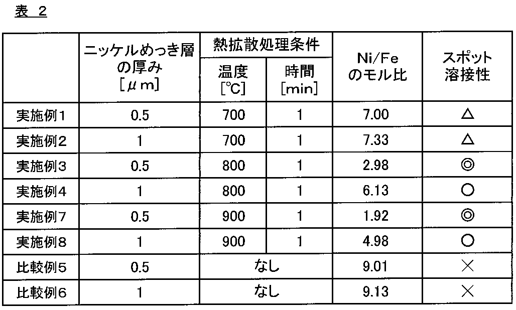
表1,2および図1に示すように、鉄-ニッケル拡散層の最表層におけるNi/Feのモル比が7.5以下であり、かつ、鉄-ニッケル拡散層の厚みが0.6μm以上である実施例1~8は、平均腐食電流密度の値が、いずれも20mA/dm2以下である6.5mA/dm2以下の値となり、電池容器の内面側から非水電解液中への鉄やニッケルの溶出が有効に抑制されたものであった。また、スポット溶接性の評価を行った実施例1~4,7,8については、スポット溶接性の評価結果が良好であり、溶接性に優れているという結果となった。
これに対し、鉄-ニッケル拡散層の厚みが0.6μm未満である比較例1~4は、平均腐食電流密度の値が、いずれも20mA/dm2超である26.9mA/dm2以上の値となり、電池容器の内面側から非水電解液中へ鉄やニッケルが溶出したという結果となった。また、熱拡散処理を実施せず、最表面におけるNi/Feのモル比が7.5超である比較例5,6は、スポット溶接性の評価結果が悪く、溶接性に劣るという結果となった。
Claims (4)
- 電解液として非水電解液を用いる電池の電池容器を形成するための電池容器用表面処理鋼板であって、
鋼板の、少なくとも電池容器の内面側となる面にニッケルめっき層を形成した後に、熱拡散処理を行うことにより形成された鉄-ニッケル拡散層を有し、
前記鉄-ニッケル拡散層の最表層におけるNiとFeとの比率が、Ni/Feのモル比で7.5以下であり、かつ、前記鉄-ニッケル拡散層の厚みが0.6μm以上であることを特徴とする電池容器用表面処理鋼板。 - 熱拡散処理を施す前における前記ニッケルめっき層の厚みが1.0μm以下であることを特徴とする請求項1に記載の電池容器用表面処理鋼板。
- 請求項1または2に記載の電池容器用表面処理鋼板を成形加工してなる電池容器。
- 請求項3に記載の電池容器を用いてなる電池。
Priority Applications (3)
| Application Number | Priority Date | Filing Date | Title |
|---|---|---|---|
| KR1020157002705A KR102195377B1 (ko) | 2012-08-29 | 2013-08-20 | 전지 용기용 표면 처리 강판, 전지 용기 및 전지 |
| US14/627,902 US9911948B2 (en) | 2012-08-29 | 2015-02-20 | Surface-treated steel sheet for battery containers, battery container, and battery |
| US15/876,894 US10665825B2 (en) | 2012-08-29 | 2018-01-22 | Surface-treated steel sheet for battery containers, battery container, and battery |
Applications Claiming Priority (2)
| Application Number | Priority Date | Filing Date | Title |
|---|---|---|---|
| JP2012188513A JP6023513B2 (ja) | 2012-08-29 | 2012-08-29 | 電池容器用表面処理鋼板、電池容器および電池 |
| JP2012-188513 | 2012-08-29 |
Related Child Applications (1)
| Application Number | Title | Priority Date | Filing Date |
|---|---|---|---|
| US14/627,902 Continuation-In-Part US9911948B2 (en) | 2012-08-29 | 2015-02-20 | Surface-treated steel sheet for battery containers, battery container, and battery |
Publications (1)
| Publication Number | Publication Date |
|---|---|
| WO2014034470A1 true WO2014034470A1 (ja) | 2014-03-06 |
Family
ID=50183285
Family Applications (1)
| Application Number | Title | Priority Date | Filing Date |
|---|---|---|---|
| PCT/JP2013/072140 Ceased WO2014034470A1 (ja) | 2012-08-29 | 2013-08-20 | 電池容器用表面処理鋼板、電池容器および電池 |
Country Status (4)
| Country | Link |
|---|---|
| US (2) | US9911948B2 (ja) |
| JP (1) | JP6023513B2 (ja) |
| KR (1) | KR102195377B1 (ja) |
| WO (1) | WO2014034470A1 (ja) |
Cited By (1)
| Publication number | Priority date | Publication date | Assignee | Title |
|---|---|---|---|---|
| CN107408641A (zh) * | 2015-03-31 | 2017-11-28 | Fdk株式会社 | 电池壳形成用钢板以及碱性电池 |
Families Citing this family (13)
| Publication number | Priority date | Publication date | Assignee | Title |
|---|---|---|---|---|
| WO2012105636A1 (ja) * | 2011-02-02 | 2012-08-09 | 株式会社Gsユアサ | 電池システム |
| EP3269847A4 (en) | 2015-03-13 | 2018-11-07 | Toyo Kohan Co., Ltd. | Method for producing surface-treated steel sheet for battery containers, and surface-treated steel sheet for battery containers |
| CN108291323B (zh) * | 2015-12-03 | 2021-02-23 | 东洋钢钣株式会社 | 电池罐用镀镍热处理钢板 |
| EP3613867B1 (en) | 2017-04-19 | 2022-01-12 | Nippon Steel Corporation | Cold rolled steel sheet for drawn can and method for manufacturing same |
| KR102416183B1 (ko) | 2018-04-13 | 2022-07-05 | 닛폰세이테츠 가부시키가이샤 | Ni 확산 도금 강판 및 Ni 확산 도금 강판의 제조 방법 |
| KR102428145B1 (ko) | 2018-04-13 | 2022-08-02 | 닛폰세이테츠 가부시키가이샤 | Ni 확산 도금 강판 및 Ni 확산 도금 강판의 제조 방법 |
| WO2020009212A1 (ja) | 2018-07-06 | 2020-01-09 | 日本製鉄株式会社 | 表面処理鋼板および表面処理鋼板の製造方法 |
| WO2020009213A1 (ja) | 2018-07-06 | 2020-01-09 | 日本製鉄株式会社 | 表面処理鋼板および表面処理鋼板の製造方法 |
| KR102383727B1 (ko) | 2019-07-16 | 2022-04-07 | 주식회사 티씨씨스틸 | 내식성이 우수한 니켈 도금 열처리 강판 제조 방법 및 이로부터 제조된 니켈 도금 열처리 강판 |
| KR102477435B1 (ko) * | 2020-12-09 | 2022-12-15 | 주식회사 티씨씨스틸 | 가공성이 우수한 니켈 도금 열처리 강판 및 이의 제조방법 |
| JP7381985B2 (ja) * | 2021-11-12 | 2023-11-16 | 日本製鉄株式会社 | 溶接部材 |
| KR20250097856A (ko) | 2022-10-28 | 2025-06-30 | 도요 고한 가부시키가이샤 | Ni 도금 강판 및 전지 용기 |
| JPWO2024090569A1 (ja) | 2022-10-28 | 2024-05-02 |
Citations (3)
| Publication number | Priority date | Publication date | Assignee | Title |
|---|---|---|---|---|
| JP2002208382A (ja) * | 2001-01-09 | 2002-07-26 | Nippon Steel Corp | アルカリマンガン電池正極缶用Niメッキ鋼板 |
| JP2005085479A (ja) * | 2003-09-04 | 2005-03-31 | Nippon Steel Corp | 非水電解液電池ケース用Niメッキ鋼板およびこの鋼板を用いた電池ケース |
| JP2008041527A (ja) * | 2006-08-09 | 2008-02-21 | Matsushita Electric Ind Co Ltd | 電池缶及びそれを用いた電池 |
Family Cites Families (4)
| Publication number | Priority date | Publication date | Assignee | Title |
|---|---|---|---|---|
| JPH11204146A (ja) | 1998-01-16 | 1999-07-30 | Hitachi Maxell Ltd | 有機電解液二次電池およびその製造方法 |
| JP2005041527A (ja) | 2003-07-22 | 2005-02-17 | Konan Rubber Kk | 紙袋 |
| US20120009464A1 (en) * | 2009-03-31 | 2012-01-12 | Makoto Nakazawa | Material for metal case of secondary battery using non-aqueous electrolyte, metal case, secondary battery, and producing method of material for metal case |
| SG176768A1 (en) * | 2009-06-09 | 2012-01-30 | Toyo Kohan Co Ltd | Nickel-plated steel sheet and process for producing battery can using the nickel-plated steel sheet |
-
2012
- 2012-08-29 JP JP2012188513A patent/JP6023513B2/ja active Active
-
2013
- 2013-08-20 WO PCT/JP2013/072140 patent/WO2014034470A1/ja not_active Ceased
- 2013-08-20 KR KR1020157002705A patent/KR102195377B1/ko active Active
-
2015
- 2015-02-20 US US14/627,902 patent/US9911948B2/en active Active
-
2018
- 2018-01-22 US US15/876,894 patent/US10665825B2/en active Active
Patent Citations (3)
| Publication number | Priority date | Publication date | Assignee | Title |
|---|---|---|---|---|
| JP2002208382A (ja) * | 2001-01-09 | 2002-07-26 | Nippon Steel Corp | アルカリマンガン電池正極缶用Niメッキ鋼板 |
| JP2005085479A (ja) * | 2003-09-04 | 2005-03-31 | Nippon Steel Corp | 非水電解液電池ケース用Niメッキ鋼板およびこの鋼板を用いた電池ケース |
| JP2008041527A (ja) * | 2006-08-09 | 2008-02-21 | Matsushita Electric Ind Co Ltd | 電池缶及びそれを用いた電池 |
Cited By (1)
| Publication number | Priority date | Publication date | Assignee | Title |
|---|---|---|---|---|
| CN107408641A (zh) * | 2015-03-31 | 2017-11-28 | Fdk株式会社 | 电池壳形成用钢板以及碱性电池 |
Also Published As
| Publication number | Publication date |
|---|---|
| KR20150040891A (ko) | 2015-04-15 |
| US9911948B2 (en) | 2018-03-06 |
| KR102195377B1 (ko) | 2020-12-24 |
| JP2014047359A (ja) | 2014-03-17 |
| US10665825B2 (en) | 2020-05-26 |
| US20150162576A1 (en) | 2015-06-11 |
| US20180145286A1 (en) | 2018-05-24 |
| JP6023513B2 (ja) | 2016-11-09 |
Similar Documents
| Publication | Publication Date | Title |
|---|---|---|
| JP6023513B2 (ja) | 電池容器用表面処理鋼板、電池容器および電池 | |
| JP6152455B2 (ja) | 電池容器用表面処理鋼板、電池容器および電池 | |
| US9997786B2 (en) | Steel foil and method for manufacturing the same | |
| CN112262225B (zh) | 二次电池正极用不锈钢箔集电体 | |
| JP6086176B1 (ja) | 非水電解液二次電池ケース用鋼板及び非水電解液二次電池ケース | |
| WO2012046879A1 (ja) | 耐食性および電気伝導性に優れたフェライト系ステンレス鋼とその製造方法、固体高分子型燃料電池セパレータおよび固体高分子型燃料電池 | |
| JP2013108146A (ja) | 集電体用アルミニウム合金箔およびその製造方法 | |
| US9887396B2 (en) | Surface-treated steel sheet for battery containers, battery container, and battery | |
| KR20220127296A (ko) | 고체 산화물형 연료 전지용 페라이트계 스테인리스강 | |
| CN105431958B (zh) | 电池容器用表面处理钢板的制造方法 | |
| JP2013222696A (ja) | 二次電池負極集電体用鋼箔 | |
| US11981108B2 (en) | Ni-plated steel sheet and manufacturing method thereof | |
| JP5130406B1 (ja) | Cu−Zn−Sn系銅合金条 | |
| JP2003253400A (ja) | ボタン型リチウム二次電池ケース用オーステナイト系ステンレス鋼およびそれを用いた電池ケース | |
| JP2002256367A (ja) | 耐膨れ性並びに溶接性に優れる密閉角形二次電池外装缶用アルミニウム合金材およびその製造方法 |
Legal Events
| Date | Code | Title | Description |
|---|---|---|---|
| 121 | Ep: the epo has been informed by wipo that ep was designated in this application |
Ref document number: 13832644 Country of ref document: EP Kind code of ref document: A1 |
|
| ENP | Entry into the national phase |
Ref document number: 20157002705 Country of ref document: KR Kind code of ref document: A |
|
| NENP | Non-entry into the national phase |
Ref country code: DE |
|
| 122 | Ep: pct application non-entry in european phase |
Ref document number: 13832644 Country of ref document: EP Kind code of ref document: A1 |