WO2014034343A1 - 回転電機及びその製造方法 - Google Patents
回転電機及びその製造方法 Download PDFInfo
- Publication number
- WO2014034343A1 WO2014034343A1 PCT/JP2013/070409 JP2013070409W WO2014034343A1 WO 2014034343 A1 WO2014034343 A1 WO 2014034343A1 JP 2013070409 W JP2013070409 W JP 2013070409W WO 2014034343 A1 WO2014034343 A1 WO 2014034343A1
- Authority
- WO
- WIPO (PCT)
- Prior art keywords
- stator
- coil
- electrical machine
- rotating electrical
- stator core
- Prior art date
- Legal status (The legal status is an assumption and is not a legal conclusion. Google has not performed a legal analysis and makes no representation as to the accuracy of the status listed.)
- Ceased
Links
Images






Classifications
-
- H—ELECTRICITY
- H02—GENERATION; CONVERSION OR DISTRIBUTION OF ELECTRIC POWER
- H02K—DYNAMO-ELECTRIC MACHINES
- H02K3/00—Details of windings
- H02K3/04—Windings characterised by the conductor shape, form or construction, e.g. with bar conductors
- H02K3/28—Layout of windings or of connections between windings
-
- B—PERFORMING OPERATIONS; TRANSPORTING
- B23—MACHINE TOOLS; METAL-WORKING NOT OTHERWISE PROVIDED FOR
- B23K—SOLDERING OR UNSOLDERING; WELDING; CLADDING OR PLATING BY SOLDERING OR WELDING; CUTTING BY APPLYING HEAT LOCALLY, e.g. FLAME CUTTING; WORKING BY LASER BEAM
- B23K10/00—Welding or cutting by means of a plasma
- B23K10/02—Plasma welding
-
- B—PERFORMING OPERATIONS; TRANSPORTING
- B23—MACHINE TOOLS; METAL-WORKING NOT OTHERWISE PROVIDED FOR
- B23K—SOLDERING OR UNSOLDERING; WELDING; CLADDING OR PLATING BY SOLDERING OR WELDING; CUTTING BY APPLYING HEAT LOCALLY, e.g. FLAME CUTTING; WORKING BY LASER BEAM
- B23K9/00—Arc welding or cutting
- B23K9/16—Arc welding or cutting making use of shielding gas
- B23K9/167—Arc welding or cutting making use of shielding gas and of a non-consumable electrode
-
- H—ELECTRICITY
- H02—GENERATION; CONVERSION OR DISTRIBUTION OF ELECTRIC POWER
- H02K—DYNAMO-ELECTRIC MACHINES
- H02K15/00—Processes or apparatus specially adapted for manufacturing, assembling, maintaining or repairing of dynamo-electric machines
- H02K15/30—Manufacture of winding connections
- H02K15/33—Connecting winding sections; Forming leads; Connecting leads to terminals
- H02K15/35—Form-wound windings
-
- H—ELECTRICITY
- H02—GENERATION; CONVERSION OR DISTRIBUTION OF ELECTRIC POWER
- H02K—DYNAMO-ELECTRIC MACHINES
- H02K3/00—Details of windings
- H02K3/04—Windings characterised by the conductor shape, form or construction, e.g. with bar conductors
- H02K3/12—Windings characterised by the conductor shape, form or construction, e.g. with bar conductors arranged in slots
-
- Y—GENERAL TAGGING OF NEW TECHNOLOGICAL DEVELOPMENTS; GENERAL TAGGING OF CROSS-SECTIONAL TECHNOLOGIES SPANNING OVER SEVERAL SECTIONS OF THE IPC; TECHNICAL SUBJECTS COVERED BY FORMER USPC CROSS-REFERENCE ART COLLECTIONS [XRACs] AND DIGESTS
- Y10—TECHNICAL SUBJECTS COVERED BY FORMER USPC
- Y10T—TECHNICAL SUBJECTS COVERED BY FORMER US CLASSIFICATION
- Y10T29/00—Metal working
- Y10T29/49—Method of mechanical manufacture
- Y10T29/49002—Electrical device making
- Y10T29/49009—Dynamoelectric machine
Definitions
- the present invention relates to a rotating electrical machine and a method for manufacturing the same.
- the rotating electric machine generates a rotating magnetic field by supplying AC power to the stator coil, and can rotate the rotor by the rotating magnetic field.
- AC energy can be output from the coil by converting mechanical energy applied to the rotor into electrical energy.
- the rotating electrical machine operates as an electric motor or a generator.
- Patent Document 1 As such a stator coil of a rotating electric machine, one in which the terminal of a segment coil is welded and connected is known (for example, Patent Document 1).
- the present application includes a plurality of means for solving the above-described problems.
- a stator core in which a plurality of slots arranged in the circumferential direction are formed, and the stator core is inserted into the slots of the stator core.
- a stator having a stator coil, and a rotor arranged to be rotatable with respect to the stator core via a gap, the stator coil having a rectangular cross section formed in a substantially U-shape.
- the segment coil is configured by connecting a plurality of segment coils, and the segment coil has a connection portion connected to another segment coil at an end portion, and the connection portion rotates so as to have a corner portion. Configure an electric machine.
- FIG. 3 is a perspective view of a stator core 132.
- FIG. It is a figure which shows the electromagnetic steel plate 133.
- FIG. It is a figure which shows the cross section of the rotor 150 and the stator 130.
- FIG. It is a figure which shows a star connection.
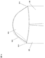
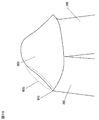
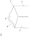
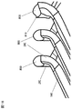
- connection part 800 of a segment coil It is a figure explaining the connection part 800 of a segment coil. It is an enlarged view which shows the connection part 800 of the segment coil shown in FIG. It is a figure which shows the connection part. It is a figure which shows the connection part. It is a figure which shows the connection part. It is a figure which shows the connection part. It is a figure which shows the connection part. It is a figure which shows the connection part. It is a figure which shows the connection part. It is a figure which shows the connection part. It is a figure which shows the connection part.
- the rotating electrical machine according to the present embodiment is a rotating electrical machine that is suitable for use in driving an automobile.
- a so-called electric vehicle using a rotating electric machine includes a hybrid type electric vehicle (HEV) having both an engine and a rotating electric machine, and a pure electric vehicle (EV) that runs only by the rotating electric machine without using an engine.
- HEV hybrid type electric vehicle
- EV pure electric vehicle
- FIG. 1 is a schematic diagram showing an overall configuration of a rotating electrical machine 100 according to an embodiment of the present invention.
- the inside of the rotating electrical machine 100 is shown by making a part of the rotating electrical machine 100 into a cross section.
- the rotating electrical machine 100 is disposed inside the case 10, and includes a housing 112, a stator 130 having a stator core 132 fixed to the housing 112, and the inside of the stator. And a rotor 150 disposed rotatably.
- the case 10 includes an engine case and a transmission case.
- This rotating electrical machine 100 is a three-phase synchronous motor with a built-in permanent magnet.
- the rotating electrical machine 100 operates as an electric motor that rotates the rotor 150 when a three-phase alternating current is supplied to the stator coil 138 wound around the stator core 132. Further, when the rotating electrical machine 100 is driven by an engine, it operates as a generator and outputs three-phase AC generated power. That is, the rotating electrical machine 100 has both a function as an electric motor that generates rotational torque based on electric energy and a function as a generator that generates electric power based on mechanical energy. Functions can be used selectively.
- the stator 130 is fixed to the housing 112.
- the stator 130 is fixedly held in the case 10 by a flange 115 provided on the housing 112 being fastened to the case 10 by bolts 12.
- the rotor 150 fixed to the shaft 118 is supported by the bearings 14 ⁇ / b> A and 14 ⁇ / b> B of the case 10, and is rotatably held inside the stator core 132.
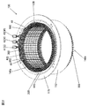
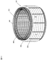
- FIG. 2 is a perspective view showing the stator 130 attached to the housing 112.
- the housing 112 is formed into a cylindrical shape by drawing a steel plate (such as a high-tensile steel plate) having a thickness of about 2 to 5 mm.
- a flange 115 is provided at one end of the housing 112 in the axial direction, and is folded and bolted to the case 10 as described above (see FIG. 1).
- the flange 115 is formed integrally with the housing 112 by drawing. Note that the stator 130 may be directly fixed to the case 10 without providing the housing 112.
- the stator 130 is fixed to the inner peripheral side of the housing 112, and includes a cylindrical stator core 132 and a stator coil 138 attached to the stator core 132.
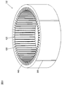
- FIG. 3 is a perspective view of the stator core 132.
- the stator core 132 is formed by laminating a plurality of electromagnetic steel plates 133 as shown in FIG.
- the electromagnetic steel sheet 133 has a thickness of about 0.05 to 1.0 mm and is formed by punching or etching.
- the laminated electromagnetic steel sheets 133 are fixed by welding. In the example shown in FIG. 3, the weld 200 shows it.
- the electromagnetic steel plates 133 stacked by this welding are connected, and deformation of the electromagnetic steel plates 133 due to the tightening force when press-fitted into the housing 112 is suppressed.
- the stator core 132 is formed with a plurality of slots 420 extending in the axial direction at equal intervals in the circumferential direction.
- the number of slots 420 is, for example, 72 in this embodiment.
- the stator coil 138 is accommodated in the slot 420.
- the slot 420 is an open slot, and an opening is formed on the inner peripheral side of the stator core.
- the circumferential width of the opening is substantially the same as or slightly smaller than the coil mounting portion of each slot 420 in which the stator coil 138 is mounted.
- an insulating paper 300 is disposed in each slot 420.
- the insulating paper 300 is disposed in the slot 420 and the coil ends 140a and 140b.
- the insulating paper 300 is disposed between the coils inserted into the slot 420 and between the coil and the inner surface of the slot 420.
- the withstand voltage between the inner surface of 420 is improved.
- the insulating paper 300 disposed in the coil ends 140a and 140b is disposed in an annular shape between the coils for interphase insulation and interconductor insulation in the coil ends 140a and 140b.
- the insulating paper 300 is an insulating sheet made of heat-resistant polyamide paper, for example, and has a thickness of about 0.1 to 0.5 mm.
- Teeth 430 are formed between the slots 420, and each tooth 430 is integrated with an annular core back 440.
- the stator core 132 is an integral core in which the teeth 430 and the core back 440 are integrally molded.
- the teeth 430 serve to guide the rotating magnetic field generated by the stator coil 138 to the rotor 150 and generate a rotating torque in the rotor 150.
- the stator core 132 shown in FIG. 3 is fitted and fixed to the inside of the cylindrical housing 112 by shrink fitting.
- a stator core 132 is first arranged, and a housing 112 that has been heated in advance and expanded in inner diameter by thermal expansion is fitted into the stator core 132.
- the housing 112 is cooled to shrink the inner diameter, whereby the outer peripheral portion of the stator core 132 is tightened by the heat shrinkage.
- the stator core 132 has an inner diameter dimension of the housing 112 that is smaller than an outer diameter dimension of the stator core 132 by a predetermined value so that the stator core 132 does not idle with respect to the housing 112 due to a reaction caused by the torque of the rotor 150 during operation. Set to. As a result, the stator core 132 is firmly fixed in the housing 112 by shrink fitting. The difference between the outer diameter of the stator core 132 and the inner diameter of the housing 112 at room temperature is called a tightening allowance. By setting this allowance assuming the maximum torque of the rotating electrical machine 100, the housing 112 has a predetermined tightening force. Thus, the stator core 132 can be held.
- the stator core 132 is not limited to being fitted and fixed by shrink fitting, but may be fitted and fixed to the housing 112 by press fitting.
- FIG. 5 is a diagram for explaining the rotor 150, and shows a cross section of the rotor 150 and the stator 130.
- the stator coil 138 and the insulating paper 300 housed in the shaft 118 and the slot 420 are omitted.
- the rotor 150 includes a rotor core 152 and permanent magnets 154 held in magnet insertion holes formed in the rotor core 152.
- rectangular parallelepiped magnet insertion holes are formed at equal intervals in the circumferential direction in the vicinity of the outer peripheral portion.
- a permanent magnet 154 is embedded in each magnet insertion hole and fixed with an adhesive or the like.
- the width of the magnet insertion hole in the circumferential direction is larger than the width of the permanent magnet 154 in the circumferential direction, and magnetic gaps 156 are formed on both sides of the permanent magnet 154.
- the magnetic gap 156 may be embedded with an adhesive, or may be solidified integrally with the permanent magnet 154 with a resin.
- the permanent magnet 154 forms the field pole of the rotor 150.
- one magnetic pole is formed by one permanent magnet 154, but one magnetic pole may be formed by a plurality of permanent magnets. By increasing the number of permanent magnets for forming each magnetic pole to a plurality, the magnetic flux density of each magnetic pole emitted from the permanent magnet increases, and the magnet torque can be increased.
- the magnetization direction of the permanent magnet 154 is directed in the radial direction, and the direction of the magnetization direction is reversed for each field pole. That is, if the surface on the stator side of the permanent magnet 154 for forming a certain magnetic pole is magnetized to the N pole and the surface on the shaft side is magnetized to the S pole, the stator side of the permanent magnet 154 that forms the adjacent magnetic pole is assumed. The surface is magnetized so as to be the south pole and the shaft side surface is the north pole.
- the 12 permanent magnets 154 are magnetized so as to change the magnetization direction alternately for each magnetic pole at equal intervals in the circumferential direction, so that the rotor 150 forms 12 magnetic poles. ing.
- the permanent magnet 154 may be magnetized and embedded in the magnet insertion hole of the rotor core 152, or may be inserted into the magnet insertion hole of the rotor core 152 before being magnetized, and then magnetized by applying a strong magnetic field. You may do it.
- the magnetized permanent magnet 154 has a strong magnetic force, and if the magnet is magnetized before the permanent magnet 154 is fixed to the rotor 150, a strong attraction between the permanent magnet 154 and the rotor core 152 is obtained. A force is generated, and this suction force hinders work. Moreover, there is a possibility that dust such as iron powder adheres to the permanent magnet 154 due to the strong attractive force. Therefore, in order to improve the productivity of the rotating electrical machine 100, it is desirable that the permanent magnet 154 is magnetized after being inserted into the magnet insertion hole of the rotor core 152.
- neodymium-based, samarium-based sintered magnets, ferrite magnets, neodymium-based bonded magnets, and the like can be used for the permanent magnet 154.
- the residual magnetic flux density of the permanent magnet 154 is 0.4 to 1..
- About 3T is desirable, and a neodymium magnet is more suitable.
- the auxiliary magnetic pole 160 is formed between the permanent magnets 154 forming the magnetic pole.
- the auxiliary magnetic pole 160 acts so that the magnetic resistance of the q-axis magnetic flux generated by the stator coil 138 is reduced.
- the auxiliary magnetic pole 160 causes the magnetic resistance of the q-axis magnetic flux to be much smaller than the magnetic resistance of the d-axis magnetic flux, so that a large reluctance torque is generated.
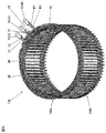
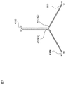
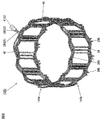
- FIG. 6 is a perspective view showing a stator coil 138 for three phases. The stator coils 138 are connected in a star connection configuration as shown in FIG.
- a two-star stator coil 138 in which two star connections are connected in parallel is employed. That is, it has a U1 phase, V1 phase and W1 phase star connection, and a U2 phase, V2 phase and W2 phase star connection, and the U1 and U2 phase lead wires are combined together by an AC terminal 41U.
- the V1 and V2 phase lead wires are grouped together by an AC terminal 41V, and the W1 and W2 phase lead wires are grouped together by an AC terminal 41W.
- N1 and N2 are neutral points of the respective star connections.
- the stator coil 138 uses oxygen-free copper or aerobic copper.
- oxygen content is about 10 ppm to about 1000 ppm.
- the stator coil 138 is wound by a distributed winding method.
- the distributed winding is a winding method in which the phase-wound coil is wound around the stator core 132 so that the phase-wound coil is accommodated in two slots 420 that are separated across the plurality of slots 420.
- distributed winding is adopted as the winding method, so that the formed magnetic flux distribution is closer to a sine wave than concentrated winding, and has a feature that reluctance torque is likely to be generated. Therefore, this rotating electrical machine 100 has improved controllability using field-weakening control and reluctance torque, and can be used over a wide rotational speed range from a low rotational speed to a high rotational speed, and is suitable for an electric vehicle. Excellent motor characteristics can be obtained.
- the stator coil 138 may be round or square in cross section. However, there is a tendency for the efficiency to be improved by using the cross-section inside the slot 420 as effectively as possible and reducing the space in the slot. Is desirable.
- the square shape of the cross section of the stator coil 138 may be a shape in which the circumferential direction of the stator core 132 is short and the radial direction is long, or conversely, the circumferential direction is long and the radial direction is short. It may be.
- the stator coil 138 is a rectangular coil in which the rectangular cross section of the stator coil 138 is long in the circumferential direction of the stator core 132 and short in the radial direction of the stator core 132 in each slot 420. in use. Further, the outer periphery of this flat coil is covered with an insulating film 600.
- the stator coil 138 shown in FIG. 6 has a total of six coils (U1, U2, V1, V2, W1, W2) attached to the stator core 132 in close contact with each other.
- the six coils constituting the stator coil 138 are arranged at appropriate intervals by the slot 420.
- AC terminals 41U, 41V, 41W, which are input / output terminals for UVW three-phase, and a neutral wire connecting portion 40 are arranged on one coil end 140a side of the stator coil 138. ing.
- the AC terminals 41U, 42V, and 43W for receiving the three-phase AC power protrude from the coil end 140a outward in the axial direction of the stator core 132.
- the stator 130 is connected to a power converter (not shown) via the AC terminals 41U, 42V, and 43W, so that AC power is supplied.
- the coil ends 140a and 140b which are portions protruding outward in the axial direction from the stator core 132, are arranged in an orderly manner as a whole, leading to a reduction in the size of the entire rotating electrical machine. effective. Further, the orderly arrangement of the coil ends 140a and 140b is desirable from the viewpoint of improving the reliability with respect to the insulation characteristics.
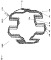
- FIG. 8 is a perspective view showing a U-phase stator coil 138U wound around the stator core 132.
- FIGS. 9 and 10 are perspective views showing a U1-phase stator coil 138U1 and a U2-phase stator coil 138U2 constituting the stator coil 138U.
- the stator coil 138 is a segment type coil formed by connecting a plurality of U-shaped segment coils 28 to each other.
- the segment coil 28 has a top portion 28c disposed at one coil end 140a. Further, both end portions 28E and 28E of the segment coil 28 are connected to the other segment coil 28 at the other coil end 140b.
- FIG. 11 is a diagram showing a segment coil connection portion 800.
- the connecting portions are arranged at an appropriate interval from each other.
- the connection method is arc welding TIG welding, plasma welding, or the like.
- the copper wire base material is melted and connected.
- As the shielding gas argon, helium, or a mixed gas of argon and helium is used.
- FIG. 12 is an enlarged view of the segment coil connecting portion 800 shown in FIG. 11 as viewed from the radial direction.
- the corner portion 810 remains after welding.
- the coil end 140b can be made small by the corner portion 810.
- FIG. 13 is a detailed view when viewed from the circumferential direction of the connecting portion 800 of FIG. 12 (hereinafter, FIGS. 14-16 are also views seen from the circumferential direction in the same manner).
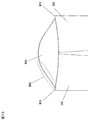
- corner portions 810 are formed on both sides in the radial direction of the connecting portion. That is, the welded portion is formed in a mountain shape, leaving the corner portion 810.
- corner portion 810 is formed so as to protrude in the axial direction from base 830 of the mountain-shaped welded portion. With such a shape, the coil end 140b can be further reduced.
- FIG. 14 is a detailed view of another form of the connecting portion 800 of FIG.
- the welded portion is large in order to increase the connection area. That is, the skirt 830 portion of the mountain-shaped welded portion is larger than the example of FIG. 13, and the corner portion 810 is configured to be connected to the skirt 830 of the mountain-shaped welded portion (right side in FIG. 14). Also in the present embodiment, since the surface tension of the welded portion is small and the corner portions 810 are formed on both sides, the coil end 140b can be further reduced. In addition, what is necessary is just to implement toward the down side (gravity direction) at the time of welding, for example, when taking a connection area large.
- FIG. 15 is a detailed view of another form of the connecting portion 800 of FIG.
- the welded portion is further increased as compared with FIG. That is, the corner portion 810 is configured to be connected to the skirt 830 of the mountain-shaped welded portion in one radial direction, and the welded portion is configured to protrude outward in the radial direction of the base material in the other radial direction.
- the corner portion 810 only needs to be configured on one side in the radial direction, and the shape of the corner portion 810 projects from the skirt 830 in the axial direction as shown in FIG. It may be a simple shape.
- the coil end 140b can be made small.
- what is necessary is just to implement toward the down side (gravity direction) at the time of welding, for example, when taking a connection area large.
- FIG. 16 is a detailed view of another form of the connection unit 800 of FIG.
- the corner portion 810 is provided, and the base 830 of the mountain-shaped welded portion is configured to be recessed in the axial direction.
- the shape of the corner portion 810 may be a shape protruding in the axial direction as shown in FIG. 13 or a shape connected to the skirt 830 of the mountain-shaped welded portion, but the skirt 830 as shown in FIG.
- the connection area is larger when the shape is connected to.
- the coil end 140b can be made small.
- what is necessary is just to implement toward the down side (gravity direction) at the time of welding, for example, when taking a connection area large.
- FIG. 17 is a detailed view of another form of the connecting portion 800 of FIG. 12, and is a view of the connecting portion 800 as viewed from the radial direction.
- corner portion 810 is configured as a part of the radial end surface of connection portion 800.
- the coil end 140b can be made small.
- FIG. 18 is a detailed view of another form of the connecting portion 800 of FIG.
- a connection portion having a corner portion 810 is provided at a part of the coil end. Even in such a form, the coil end 140b can be made small because the surface tension is small and the corner portion 810 is partially formed.
- the rotating electric machine having a permanent magnet in the rotor has been described as an example.
- the present invention can be similarly applied to a stator of a rotating electric machine such as an induction motor.
- the present invention can be applied to other than the rotating electric machine for driving the vehicle.
- a part of the configuration of one embodiment can be replaced with the configuration of another embodiment, and the configuration of another embodiment can be added to the configuration of one embodiment. .
Landscapes
- Engineering & Computer Science (AREA)
- Power Engineering (AREA)
- Manufacturing & Machinery (AREA)
- Physics & Mathematics (AREA)
- Plasma & Fusion (AREA)
- Mechanical Engineering (AREA)
- Windings For Motors And Generators (AREA)
- Iron Core Of Rotating Electric Machines (AREA)
- Manufacture Of Motors, Generators (AREA)
Abstract
Description
記課題を解決する手段を複数含んでいるが、その一例を挙げるならば、周方向に並んだ複数のスロットが形成された固定子鉄心、および当該固定子鉄心の前記スロット内に挿入された固定子コイルを有する固定子と、前記固定子鉄心に対して隙間を介して回転可能に配置された回転子と、を備え、前記固定子コイルは、略U字形状に成形された矩形断面の導体からなる複数のセグメントコイルが複数接続されることにより構成され、前記セグメントコイルは端部に他のセグメントコイルと接続された接続部を有し、前記接続部は角部を有するように回転電機を構成する。
(回転電機の全体構成)
本実施形態に係る回転電機は、自動車の走行に使用するのが好適な回転電機である。ここで、回転電機を使用するいわゆる電気自動車には、エンジンと回転電機の両方を備えるハイブリッドタイプの電気自動車(HEV)と、エンジンを用いないで回転電機のみで走行する純粋な電気自動車(EV)とがあるが、以下に説明する回転電機は両方のタイプに利用できるので、ここでは代表してハイブリッドタイプの自動車に用いられる回転電機に基づいて説明する。
(固定子コイルの説明)
図6は、三相分の固定子コイル138を示す斜視図である。固定子コイル138は図7に示すようなスター結線の構成で接続されている。本実施の形態では、2つにスター結線が並列接続された2スター構成の固定子コイル138が採用されている。すなわち、U1相、V1相およびW1相のスター結線と、U2相、V2相およびW2相のスター結線とを備えており、U1およびU2相の口出し線は交流端子41Uにより1つに纏められ、V1およびV2相の口出し線は交流端子41Vにより1つに纏められ、W1およびW2相の口出し線は交流端子41Wにより1つに纏められている。N1およびN2はそれぞれのスター結線の中性点である。
した実施の形態では回転子に永久磁石を備えた回転電機を例に説明したが、本発明は、誘導モータ等の回転電機の固定子にも同様に適用することができる。また、車両駆動用回転電機以外にも適用できる。また、ある実施の形態の構成の一部を他の実施の形態の構成に置き換えることが可能であり、また、ある実施の形態の構成に他の実施の形態の構成を加えることも可能である。
28c:頭頂部
41U,41V,41W:交流端子
100:回転電機
130:固定子
132:固定子鉄心
138,138U,138U1,138U2:固定子コイル
140a140b:コイルエンド
150:回転子
420:スロット
800:接続部
810:角部
Claims (5)
- 周方向に並んだ複数のスロットが形成された固定子鉄心、および当該固定子鉄心の前記スロット内に挿入された固定子コイルを有する固定子と、
前記固定子鉄心に対して隙間を介して回転可能に配置された回転子と、を備える回転電機において、
前記固定子コイルは、略U字形状に成形された矩形断面の導体からなる複数のセグメントコイルが複数接続されることにより構成され、
前記セグメントコイルは端部に他のセグメントコイルと接続された接続部を有し、
前記接続部は角部を有する回転電機。 - 請求項1に記載の回転電機において、
前記角部が、前記接続部を共有する2つの前記セグメントコイルの径方向端部に構成され、
前記角部の軸方向位置は、前記接続部の軸方向端部よりも固定子に近い回転電機。 - 請求項2に記載の回転電機において、
前記導体が有酸素銅からなる回転電機。 - 周方向に並んだ複数のスロットが形成された固定子鉄心、および当該固定子鉄心の前記スロット内に挿入された固定子コイルを有する固定子と、
前記固定子鉄心に対して隙間を介して回転可能に配置された回転子と、を備える回転電機の製造方法において、
矩形断面の導体を略U字形状に成形しセグメントコイルにする工程と、
前記セグメントコイルが、接続部に角部を有する形態で接続される接続工程とを備える回転電機の製造方法。 - 請求項4に記載の回転電機の製造方法において、
前記導体は有酸素銅からなり、
前記接続工程が、前記導体の前記接続部をTIG溶接又はプラズマ溶接で溶接するものであり、溶接時のシールドガスとして、アルゴン、ヘリウム、又はアルゴンとヘリウムの混合ガスを使用する回転電機の製造方法。
Priority Applications (3)
| Application Number | Priority Date | Filing Date | Title |
|---|---|---|---|
| US14/422,621 US9906086B2 (en) | 2012-08-31 | 2013-07-29 | Rotating electric machine including a stator with a connection portion having a corner portion and method for manufacturing same |
| CN201380043776.5A CN104584392B (zh) | 2012-08-31 | 2013-07-29 | 旋转电机及其制造方法 |
| DE112013004290.8T DE112013004290T5 (de) | 2012-08-31 | 2013-07-29 | Drehende elektrische Maschine und Verfahren zu ihrer Herstellung |
Applications Claiming Priority (2)
| Application Number | Priority Date | Filing Date | Title |
|---|---|---|---|
| JP2012-190814 | 2012-08-31 | ||
| JP2012190814A JP5860782B2 (ja) | 2012-08-31 | 2012-08-31 | 回転電機及びその製造方法 |
Publications (1)
| Publication Number | Publication Date |
|---|---|
| WO2014034343A1 true WO2014034343A1 (ja) | 2014-03-06 |
Family
ID=50183163
Family Applications (1)
| Application Number | Title | Priority Date | Filing Date |
|---|---|---|---|
| PCT/JP2013/070409 Ceased WO2014034343A1 (ja) | 2012-08-31 | 2013-07-29 | 回転電機及びその製造方法 |
Country Status (5)
| Country | Link |
|---|---|
| US (1) | US9906086B2 (ja) |
| JP (1) | JP5860782B2 (ja) |
| CN (1) | CN104584392B (ja) |
| DE (1) | DE112013004290T5 (ja) |
| WO (1) | WO2014034343A1 (ja) |
Families Citing this family (14)
| Publication number | Priority date | Publication date | Assignee | Title |
|---|---|---|---|---|
| EP3240147B1 (en) * | 2014-12-26 | 2022-08-10 | Hitachi Astemo, Ltd. | Method of manufacturing a rotary-electric-machine stator coil |
| US10666109B2 (en) * | 2015-09-02 | 2020-05-26 | Hitachi Automotive Systems, Ltd. | Stator coil, stator including said stator coil, and rotating electric machine including said stator |
| US20190351500A1 (en) * | 2016-03-17 | 2019-11-21 | Honda Motor Co., Ltd. | Welding method and device |
| JP6799962B2 (ja) * | 2016-08-03 | 2020-12-16 | 本田技研工業株式会社 | バスバーユニット |
| JP6677279B2 (ja) * | 2017-07-21 | 2020-04-08 | 株式会社デンソー | 回転電機 |
| JP6663942B2 (ja) | 2018-02-20 | 2020-03-13 | 本田技研工業株式会社 | 回転電機のステータ |
| US11973386B2 (en) * | 2018-05-23 | 2024-04-30 | Hitachi Astemo, Ltd. | Rotary electric machine and method of manufacturing rotary electric machine |
| US11223253B2 (en) * | 2018-07-12 | 2022-01-11 | Hitachi Astemo, Ltd. | Stator for rotating electrical machine, rotating electrical machine, and method of producing stator for rotating electrical machine |
| US11374463B2 (en) * | 2018-07-12 | 2022-06-28 | Hitachi Astemo, Ltd. | Stator for rotating electrical machine, rotating electrical machine and method of producing stator for rotating electrical machine |
| JP7172843B2 (ja) * | 2019-05-13 | 2022-11-16 | 株式会社デンソー | モータ |
| JP7276205B2 (ja) * | 2020-03-06 | 2023-05-18 | 株式会社デンソー | スロットレスモータ |
| JP7660016B2 (ja) * | 2021-04-02 | 2025-04-10 | 株式会社プロテリアル | 溶接方法、及び回転電機の製造方法 |
| EP4160875A1 (de) | 2021-10-01 | 2023-04-05 | Valeo eAutomotive Germany GmbH | Formleiter für eine wicklung eines aktivteils einer rotierenden elektrischen maschine, aktivteil für eine rotierende elektrische maschine und zugehöriges herstellungsverfahren |
| JP7022254B1 (ja) * | 2021-11-25 | 2022-02-17 | 日機装株式会社 | スロットライナおよび回転電機 |
Citations (8)
| Publication number | Priority date | Publication date | Assignee | Title |
|---|---|---|---|---|
| JPH09215280A (ja) * | 1996-01-31 | 1997-08-15 | Denso Corp | 電機子コイルの接合方法 |
| JP2000164043A (ja) * | 1998-09-22 | 2000-06-16 | Denso Corp | 接合用電線およびその接合方法 |
| JP2001054263A (ja) * | 1999-08-06 | 2001-02-23 | Denso Corp | 導体セグメント接合型の回転電機及びその製造方法 |
| JP2002119003A (ja) * | 2000-10-10 | 2002-04-19 | Mitsubishi Electric Corp | 回転電機の固定子とその製造方法 |
| JP2002204543A (ja) * | 2000-11-06 | 2002-07-19 | Denso Corp | 車両用回転電機 |
| JP2005253145A (ja) * | 2004-03-02 | 2005-09-15 | Hitachi Ltd | 回転電機 |
| JP2009081980A (ja) * | 2007-09-27 | 2009-04-16 | Hitachi Ltd | 回転電機及びその固定子 |
| JP2012115075A (ja) * | 2010-11-26 | 2012-06-14 | Denso Corp | 車両用回転電機の固定子 |
Family Cites Families (6)
| Publication number | Priority date | Publication date | Assignee | Title |
|---|---|---|---|---|
| US6181043B1 (en) | 1997-12-10 | 2001-01-30 | Denso Corporation | Alternator for vehicle |
| JP3552157B2 (ja) * | 1999-04-02 | 2004-08-11 | 株式会社デンソー | 対導線配列及び対導線の端部接合方法及びそれを用いた回転電機の巻線製造方法 |
| US6894415B2 (en) * | 2000-11-06 | 2005-05-17 | Denso Corporation | Stator arrangement of rotary electric machine |
| FR2821498B1 (fr) * | 2001-02-28 | 2004-01-16 | Valeo Equip Electr Moteur | Procede d'assemblage de segments conducteurs d'un bobinage de rotor ou de stator de machine electrique rotative |
| JP5098854B2 (ja) * | 2008-06-30 | 2012-12-12 | 株式会社デンソー | ステータコイルの溶接方法 |
| JP5510709B2 (ja) * | 2010-01-22 | 2014-06-04 | 株式会社デンソー | 回転電機の固定子 |
-
2012
- 2012-08-31 JP JP2012190814A patent/JP5860782B2/ja active Active
-
2013
- 2013-07-29 WO PCT/JP2013/070409 patent/WO2014034343A1/ja not_active Ceased
- 2013-07-29 DE DE112013004290.8T patent/DE112013004290T5/de active Pending
- 2013-07-29 CN CN201380043776.5A patent/CN104584392B/zh active Active
- 2013-07-29 US US14/422,621 patent/US9906086B2/en active Active
Patent Citations (8)
| Publication number | Priority date | Publication date | Assignee | Title |
|---|---|---|---|---|
| JPH09215280A (ja) * | 1996-01-31 | 1997-08-15 | Denso Corp | 電機子コイルの接合方法 |
| JP2000164043A (ja) * | 1998-09-22 | 2000-06-16 | Denso Corp | 接合用電線およびその接合方法 |
| JP2001054263A (ja) * | 1999-08-06 | 2001-02-23 | Denso Corp | 導体セグメント接合型の回転電機及びその製造方法 |
| JP2002119003A (ja) * | 2000-10-10 | 2002-04-19 | Mitsubishi Electric Corp | 回転電機の固定子とその製造方法 |
| JP2002204543A (ja) * | 2000-11-06 | 2002-07-19 | Denso Corp | 車両用回転電機 |
| JP2005253145A (ja) * | 2004-03-02 | 2005-09-15 | Hitachi Ltd | 回転電機 |
| JP2009081980A (ja) * | 2007-09-27 | 2009-04-16 | Hitachi Ltd | 回転電機及びその固定子 |
| JP2012115075A (ja) * | 2010-11-26 | 2012-06-14 | Denso Corp | 車両用回転電機の固定子 |
Also Published As
| Publication number | Publication date |
|---|---|
| JP5860782B2 (ja) | 2016-02-16 |
| CN104584392A (zh) | 2015-04-29 |
| US9906086B2 (en) | 2018-02-27 |
| CN104584392B (zh) | 2017-02-22 |
| JP2014050207A (ja) | 2014-03-17 |
| US20150222155A1 (en) | 2015-08-06 |
| DE112013004290T5 (de) | 2015-05-13 |
Similar Documents
| Publication | Publication Date | Title |
|---|---|---|
| JP5860782B2 (ja) | 回転電機及びその製造方法 | |
| JP6563595B2 (ja) | 回転電機、及び回転電機の固定子 | |
| JP6402257B2 (ja) | 固定子コイル、これを備えた固定子、およびこれを備えた回転電機 | |
| JP5635470B2 (ja) | 回転電機および回転電機の製造方法 | |
| CN103201931B (zh) | 旋转电机 | |
| CN110771013B (zh) | 旋转电机的定子以及旋转电机 | |
| JPWO2016035533A1 (ja) | 回転電機のステータ、及びこれを備えた回転電機 | |
| US20180248453A1 (en) | Rotor, Rotating Electric Machine Including Said Rotor, and Method of Manufacturing Said Rotor | |
| JP2013207946A (ja) | 回転電機 | |
| JP7030961B2 (ja) | 固定子、及び回転電機 | |
| JP6009519B2 (ja) | 回転電機および回転電機の製造方法 | |
| JP2014082935A (ja) | 回転電機の固定子、およびこれを備えた回転電機 | |
| JP6165828B2 (ja) | 固定子コイル、固定子鉄心、及び回転電機 | |
| WO2020246372A1 (ja) | 回転電機の固定子、端子台及び回転電機 | |
| CN112352370A (zh) | 旋转电机的定子、旋转电机以及旋转电机的定子的制造方法 |
Legal Events
| Date | Code | Title | Description |
|---|---|---|---|
| 121 | Ep: the epo has been informed by wipo that ep was designated in this application |
Ref document number: 13833224 Country of ref document: EP Kind code of ref document: A1 |
|
| WWE | Wipo information: entry into national phase |
Ref document number: 14422621 Country of ref document: US |
|
| WWE | Wipo information: entry into national phase |
Ref document number: 1120130042908 Country of ref document: DE Ref document number: 112013004290 Country of ref document: DE |
|
| 122 | Ep: pct application non-entry in european phase |
Ref document number: 13833224 Country of ref document: EP Kind code of ref document: A1 |