WO2014034204A1 - フィルタエレメント構造及び当該フィルタエレメント構造を備えた逆洗型ろ過装置 - Google Patents
フィルタエレメント構造及び当該フィルタエレメント構造を備えた逆洗型ろ過装置 Download PDFInfo
- Publication number
- WO2014034204A1 WO2014034204A1 PCT/JP2013/064726 JP2013064726W WO2014034204A1 WO 2014034204 A1 WO2014034204 A1 WO 2014034204A1 JP 2013064726 W JP2013064726 W JP 2013064726W WO 2014034204 A1 WO2014034204 A1 WO 2014034204A1
- Authority
- WO
- WIPO (PCT)
- Prior art keywords
- filter
- filter element
- fluid
- filter medium
- backwash
- Prior art date
- Legal status (The legal status is an assumption and is not a legal conclusion. Google has not performed a legal analysis and makes no representation as to the accuracy of the status listed.)
- Ceased
Links
Images


Classifications
-
- B—PERFORMING OPERATIONS; TRANSPORTING
- B01—PHYSICAL OR CHEMICAL PROCESSES OR APPARATUS IN GENERAL
- B01D—SEPARATION
- B01D29/00—Filters with filtering elements stationary during filtration, e.g. pressure or suction filters, not covered by groups B01D24/00 - B01D27/00; Filtering elements therefor
- B01D29/62—Regenerating the filter material in the filter
- B01D29/66—Regenerating the filter material in the filter by flushing, e.g. counter-current air-bumps
-
- B—PERFORMING OPERATIONS; TRANSPORTING
- B01—PHYSICAL OR CHEMICAL PROCESSES OR APPARATUS IN GENERAL
- B01D—SEPARATION
- B01D29/00—Filters with filtering elements stationary during filtration, e.g. pressure or suction filters, not covered by groups B01D24/00 - B01D27/00; Filtering elements therefor
- B01D29/11—Filters with filtering elements stationary during filtration, e.g. pressure or suction filters, not covered by groups B01D24/00 - B01D27/00; Filtering elements therefor with bag, cage, hose, tube, sleeve or like filtering elements
- B01D29/13—Supported filter elements
- B01D29/23—Supported filter elements arranged for outward flow filtration
-
- B—PERFORMING OPERATIONS; TRANSPORTING
- B01—PHYSICAL OR CHEMICAL PROCESSES OR APPARATUS IN GENERAL
- B01D—SEPARATION
- B01D29/00—Filters with filtering elements stationary during filtration, e.g. pressure or suction filters, not covered by groups B01D24/00 - B01D27/00; Filtering elements therefor
- B01D29/50—Filters with filtering elements stationary during filtration, e.g. pressure or suction filters, not covered by groups B01D24/00 - B01D27/00; Filtering elements therefor with multiple filtering elements, characterised by their mutual disposition
- B01D29/52—Filters with filtering elements stationary during filtration, e.g. pressure or suction filters, not covered by groups B01D24/00 - B01D27/00; Filtering elements therefor with multiple filtering elements, characterised by their mutual disposition in parallel connection
-
- B—PERFORMING OPERATIONS; TRANSPORTING
- B01—PHYSICAL OR CHEMICAL PROCESSES OR APPARATUS IN GENERAL
- B01D—SEPARATION
- B01D29/00—Filters with filtering elements stationary during filtration, e.g. pressure or suction filters, not covered by groups B01D24/00 - B01D27/00; Filtering elements therefor
- B01D29/50—Filters with filtering elements stationary during filtration, e.g. pressure or suction filters, not covered by groups B01D24/00 - B01D27/00; Filtering elements therefor with multiple filtering elements, characterised by their mutual disposition
- B01D29/56—Filters with filtering elements stationary during filtration, e.g. pressure or suction filters, not covered by groups B01D24/00 - B01D27/00; Filtering elements therefor with multiple filtering elements, characterised by their mutual disposition in series connection
-
- B—PERFORMING OPERATIONS; TRANSPORTING
- B01—PHYSICAL OR CHEMICAL PROCESSES OR APPARATUS IN GENERAL
- B01D—SEPARATION
- B01D29/00—Filters with filtering elements stationary during filtration, e.g. pressure or suction filters, not covered by groups B01D24/00 - B01D27/00; Filtering elements therefor
- B01D29/62—Regenerating the filter material in the filter
- B01D29/66—Regenerating the filter material in the filter by flushing, e.g. counter-current air-bumps
- B01D29/668—Regenerating the filter material in the filter by flushing, e.g. counter-current air-bumps with valves, e.g. rotating valves for coaxially placed filtering elements
-
- B—PERFORMING OPERATIONS; TRANSPORTING
- B01—PHYSICAL OR CHEMICAL PROCESSES OR APPARATUS IN GENERAL
- B01D—SEPARATION
- B01D2201/00—Details relating to filtering apparatus
- B01D2201/04—Supports for the filtering elements
- B01D2201/043—Filter tubes connected to plates
- B01D2201/0438—Filter tubes connected to plates mounted substantially vertically on plates at the lower side of the filter elements
-
- B—PERFORMING OPERATIONS; TRANSPORTING
- B01—PHYSICAL OR CHEMICAL PROCESSES OR APPARATUS IN GENERAL
- B01D—SEPARATION
- B01D2201/00—Details relating to filtering apparatus
- B01D2201/40—Special measures for connecting different parts of the filter
- B01D2201/4038—Special measures for connecting different parts of the filter for connecting at least two filtering elements together
Definitions
- the present invention relates to a filter element structure and a backwash type filtration apparatus provided with the filter element structure.
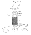
- the backwash type filtration apparatus Z includes a cylindrical filter housing 110 (hereinafter simply referred to as “housing”) 110 having two sealing covers 112 and 114.
- the housing 110 is provided with a filtration device inlet 118 through which a fluid to be filtered flows in and a filtration device outlet 120 through which the filtered fluid is discharged.
- a plurality of filter elements 122 are mounted inside the housing 110. Specifically, a plurality of filter elements 122 are arranged inside the housing 110 at intervals along a cylindrical (concentric) arc of the housing 110.
- the filter element 122 includes a filter medium 122a formed in a hollow cylindrical shape, one end of which is inserted into a through hole 114a formed in the sealing cover 114, and the other end is a sealing cap attached to the sealing cover 112. 126 is connected and sealed.
- the filter element 122 has a filter inlet 124 that is open at one end, and fluid flows into and out of the filter element 122 via the filter inlet 124. ing.
- the fluid that flows in from the filter inlet 118 flows into the filter medium 122a from the filter inlet 124 of the filter element 122, and then is filtered by passing from the inner side to the outer side of the filter medium 122a and discharged from the filter outlet 120. It has come to be.
- the arrow 121 in the figure indicates the flow direction of the fluid during the filter operation.
- the backwash type filtration device Z is provided with a drive rod (center rotating shaft) 134 and a backwash arm 130 connected to the drive rod 134. With this configuration, while performing filtration, The filter element 122 can be cleaned.
- the backwash arm (backwash pipe) 130 has an upper end abutting against the lower surface of the sealing cover 114 and a lower end connected to a pipe 132 connected to a fluid outlet for sewage. Further, the backwash arm 130 is moved under the filter inlet 124 of the filter element 122 through the drive rod 134 in order. Specifically, the backwash arm 130 operates in accordance with the rotation of the drive rod 134 and is sequentially connected to any one of the plurality of filter elements 122. Only the filter element 122 connected to the backwash arm 130 allows the fluid filtered by the other filter elements 122 to flow from the outside to the inside of the filter medium 122a. Thereby, the filter element 122 is backwashed.
- the direction of backwashing is the direction indicated by the arrow 135b in the figure (the direction from the outside to the inside of the filter element 122), and the normal filtration direction is the direction indicated by the arrow 135a (from the inside to the outside of the filter element 122).
- mold filtration apparatus which performs the backwash process similar to the above is disclosed by patent document 1, for example.
- the above-described conventional backwash type filtration device cannot sufficiently remove deposits such as dust adhering to the “filter material” constituting the filter element even if backwashing is performed.
- deposits remain and accumulate on the filter medium, and the filtration flow rate decreases. That is, the above-described conventional backwashing type filtration apparatus has been unable to efficiently filter a fluid because the filtration flow rate decreases as it is used (because the filtration capacity decreases).
- the backwashing type filtration device of the prior art allows the fluid to pass through the filter medium 122a constituting the filter element 122 and filters the fluid. Deposits d such as dust adhere to 122a.
- the filter element 122 to which dust or the like is attached is backwashed, the adhering matter d captured by the filter medium 122a of the filter element 122 is washed away as shown in FIG.
- the filter element 122 since the filter element 122 according to the prior art has a structure in which the end opposite to the filter inlet 124 (the sealing cap 126 side at the upper end of the filter medium 122a) is closed, the filter element 122 is being backwashed. A large flow of water does not occur from the upper end of the filter medium 122a toward the filter inlet 124. Therefore, in the prior art, the adhering matter d such as dust adhering to the side surface of the filter medium 122a of the filter element 122 cannot be sufficiently washed away even by backwashing (see reference numeral 140 in FIG. 10B).
- the backwashing type filtration apparatus Z of the prior art is used for the filter medium 122a (the side surface of the filter medium 122a or the upper end side of the filter medium 122a) constituting the filter element 122 when used for a predetermined period due to the structure of the filter element 122.
- the filter element 122 can be frequently replaced to prevent a reduction in filtration capacity.
- this method increases the operation cost.
- This invention is made
- the objective is to provide the backwashing type
- the present invention made to solve the above problems is a filter element structure that is attached to a backwash type filtration device and filters a fluid flowing in the device, and includes a pair of filter elements, one filter element, and the other.
- a connecting pipe for connecting the filter element to the filter element, the filter element comprising: a filter medium formed in a hollow cylindrical shape penetrating both ends; an upper cover part covering an upper end of the filter medium; and the upper cover part. And an upper hole penetrating therethrough, wherein one end of the connection pipe is connected to one upper hole, and the other end of the connection pipe is connected to the other upper hole.
- the fluid when filtering the fluid, the fluid is allowed to flow from a filter inlet formed at the lower end of the filter medium, the fluid flowing into the filter element structure is filtered through the filter medium,
- one of the filter inlets is connected to a backwash arm provided in the backwash type filtration device, and the fluid flowing in from the other filter inlet is connected to the filter medium.
- the fluid flowing outside the one filter element passes through the one filter medium and flows into the one filter medium cylinder. It is desirable that the fluid flows from one of the upper holes toward one of the filter inlets to wash away the adhering matter adhering to one of the filter media.
- the filter element structure of the present invention employs a configuration in which a pair of filter elements and a connection pipe that connects one of the filter elements and the other filter element are provided.
- the present invention enhances the cleaning effect of the deposits adhering to the filter medium by connecting the “connecting pipe to the upper lid”. Further, the present invention eliminates the need to newly provide an external power source, a control circuit, or the like in order to operate the above-described configuration (connection pipe) that enhances the cleaning effect.
- a filter element structure capable of suppressing the reduction is realized.
- the connecting pipe is provided in a U shape. With this configuration, when backwashing the filter element structure, the fluid flowing in from the other filter inlet that is not in communication with the backwash arm is smoothly connected to one of the backwash arms via the connecting pipe. The cleaning effect of deposits that flow into the filter element and adhere to the filter medium is further enhanced.
- the present invention is applied to a backwash type filtration apparatus that includes a substantially hollow cylindrical housing that houses a plurality of filter element structures, and that sequentially cleans the filter elements while filtering the fluid flowing in from the outside.
- the backwashing type filtration device includes a shelf board that divides the interior of the housing into two areas, an upper area and a lower area, and a fluid that is to be filtered is formed in the lower area.
- the filter element includes a filter medium formed in a hollow cylindrical shape penetrating both ends, and an upper lid that covers an upper end portion of the filter medium And a plurality of through holes are formed in the shelf plate, and a lower end portion of the filter element is fitted and fixed to each through hole.
- the lower area of the housing communicates with the inside of the cylinder of the filter medium, and the backwash arm moves while one end thereof is in contact with the lower end surface of the shelf board, and any one of the plurality of through holes.
- the pair of filter elements are connected to the through-holes and communicated with the filter elements inserted and fixed in the connected through-holes, and each of the pair of filter elements is not in communication with the backwash arm.
- the fluid flowing in from the apparatus inlet flows into the filter medium cylinder through the through-hole, and the flowed-in fluid passes through the filter medium and the fluid is filtered.
- the pair of filter elements that are discharged and one of the pair of filter elements is in communication with the backwash arm, the pair of filter elements that are not in communication with the backwash arm,
- the fluid flowing in from the filter inlet passes through the connecting pipe and flows into one of the filter media, and the fluid flowing outside the one filter element passes through the one filter media and passes through the one filter media.
- By flowing into the cylinder of the filter medium fluid flows from one of the upper holes toward one of the filter inlets, and the adhering matter adhering to the one of the filter medium is washed away.
- the cleaning effect of the deposits adhering to the filter medium of the filter element (cleaning effect by backwashing) can be enhanced, so that the filtration flow rate is reduced due to use. It is possible to provide a backwash type filtration device that can be suppressed.
- a filter element structure capable of suppressing a decrease in the filtration flow rate and a backwashing type filtration apparatus including the filter element structure.
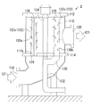
- FIG. 1 is the schematic diagram which showed the whole structure of the backwashing type
- FIG. 2 is a component development view of the filter element of the present embodiment.
- FIG. 3 is a plan view showing an arrangement state of the connecting pipe of the backwashing type filtration apparatus of the present embodiment.
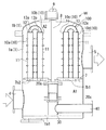
- the backwashing type filtration apparatus W of the present embodiment includes a hollow cylindrical housing 1 in which a plurality of filter elements 10 are housed, while filtering the fluid flowing from the outside of the housing 1.
- the filter elements 10 are cleaned in order.
- the structure of the backwashing type filtration apparatus W of this embodiment is demonstrated in order.
- this embodiment since this embodiment has the characteristics in the structure of the filter element 10, the structure of the filter element 10 is demonstrated in detail and description of the other structure is simplified.
- the housing 1 includes a hollow cylindrical main body 1a having an open top and a bottom 1a1, and a dome-shaped lid 1b that closes the upper end of the main body 1a. Further, the housing 1 is provided with a shelf 7 inside, and the inside of the housing 1 is partitioned into an entrance side area (lower area) A1 and an exit side area (upper area) A2 by the shelf board 7. . Further, the main body 1a is formed with a device inlet 4 for allowing a fluid to flow into the inlet-side area A1 on the side surface on the lower end side. Further, the main body 1a is formed with a device outlet 5 on the side surface on the upper end side for discharging the fluid filtered from the outlet side area A2.
- the shelf board 7 is formed in a disc shape, and a through hole 7a into which the rotary shaft 8 is rotatably inserted is formed at the center thereof.
- the shelf plate 7 is formed with a plurality of through holes 7b1 and 7b2 on a concentric circle centering on the through hole 7a (the plurality of through holes 7b1 and 7b2 are formed at predetermined intervals). .
- through holes 7b1 and 7b2 are formed in two concentric circles (inner circle and outer circle) having different radii, respectively.
- the lower end part of the filter element 10 is airtightly fitted and fixed to each through-hole 7b1 and 7b2, and thereby, the plurality of filter elements 10 are supported and fixed to the shelf plate 7.
- the inlet-side area A1 of the housing 1 communicates with the inside of the filter element 10 (filter medium 11). If the fluid flowing into the housing 1 does not pass through the tube of the filter element 10 (filter medium 11), the fluid flows from the inlet side area A1 (or outlet side area A2) to the outlet side area A2 (or inlet side area A1). It cannot be moved.
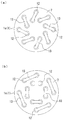
- the eight filter elements 10 are fitted and fixed in the through holes 7b1 formed on the inner circle of the shelf board 7, and the eight filters are inserted in the through holes 7b2 formed on the outer circle of the shelf board 7.
- the element 10 is fitted and fixed.
- a rotating shaft 8 extending from the top of the lid 1b toward the shelf 7 is provided.
- One end (upper end) of the rotary shaft 8 is connected to a motor 9 attached to the upper end of the lid 1 and is rotated by driving of the motor 9.
- the other end (lower end) of the rotary shaft 8 is inserted through the through hole 7a of the shelf board 7 and protrudes to the entrance side area A1.
- the motor 9 is driven by being controlled by a control circuit (not shown).
- a backwash arm (backwash pipe) 20 is connected to the lower end of the rotary shaft 8 extending to the entrance side area A1 of the housing 1.
- the backwash arm 20 is formed integrally with a base portion 20a fixed to the lower end portion of the rotary shaft 8, and the upper end surface of the backwash arm 20 rotates together with the rotary shaft 8 while sealing the lower surface of the shelf board 7 in a watertight manner. ing.
- the backwash arm 20 includes a base portion 20a, a vertical tube 20b connected to the base portion 20a, and two L-shaped tubes 20c and 20d connected to side portions of the vertical tube 20b.
- the vertical pipe 20b is rotatably fitted to a discharge pipe 30 whose upper end is sealed by a base 20a and whose lower end communicates with the backwash liquid discharge port 40.
- the L-shaped tube 20 c is connected at one end to the side surface of the vertical tube 20 b and communicates with the vertical tube 20, and the upper end surface formed at the other end is in contact with the lower surface of the shelf plate 7.
- the length of the L-shaped tube 20c is designed so that the upper end surface rotates along a plurality of through holes 7b1 formed on the shelf board 7.
- the L-shaped tube 20d has one end connected to the side surface of the vertical tube 20b and communicates with the vertical tube 20b, and the upper end surface formed at the other end is in contact with the lower surface of the shelf board 7.
- the length of the L-shaped tube 20d is designed so that the upper end surface rotates along a plurality of through holes 7b2 formed in the shelf plate 7.
- the backwash arm 20 operates in accordance with the rotation of the rotary shaft 8 rotated by the motor 9, and the upper end surfaces of the L-shaped tubes 20c and 20d are in close contact with the lower surface of the shelf plate 7 and the lower end portion of the filter element 10 is fitted. It arrange
- the backwash arm 20 has the upper end surfaces of the L-shaped tubes 20c and 20d rotated intermittently (or continuously) while sealing the shelf 7, and the filter inlet 19 at the lower end portion of the filter element 10 in sequence. Communicate with.
- the L-shaped tube 20c is operated by the motor 9 that is controlled by a control circuit (not shown), and the upper end surface thereof is connected to one of the plurality of through holes 7b1 formed in the shelf plate 7.
- the L secondary pipe 20c is connected to the filter element 10 fitted and fixed to the through hole 7b1 via the connected through hole 7b1 (the L-shaped pipe 20c and the hollow cylindrical shape are formed).
- the inside of the cylinder of the filter medium 11 communicates).
- the L-shaped tube 20d is operated by the motor 9 operated under the control of the control circuit, and the upper end surface thereof is connected to any of the plurality of through holes 7b2 formed in the shelf plate 7.
- the L-shaped tube 20d is connected to the filter element 10 fitted and fixed to the through-hole 7b2 via the connected through-hole 7b2 (the L-shaped tube 20d and the hollow tube-shaped are formed.
- the inside of the cylinder of the filter medium 11 communicates).
- the L-shaped tube 20 c and the L-shaped tube 20 d are not connected to both of the pair of filter elements 10 connected by the connecting tube 13 described later, and the through holes 7 b 1 and 7 b 2 are connected. And the L-shaped tubes 20c and 20d may be appropriately arranged.
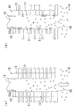
- the filter element 10 has a filter medium 11 formed in a hollow cylindrical shape penetrating both ends, a plate-like upper lid portion 12 that covers the upper end portion of the filter medium 11, and an upper hole 12 a that penetrates the upper lid portion 12.
- the filter medium 11 is not particularly limited as long as it can be filtered by passing a fluid and can be backwashed.
- the filter medium 11 may be formed by winding a wire mesh or a notch wire around a cylindrical frame (filter frame) to form a hollow cylinder.
- a notch wire around the frame will be described in detail, and each configuration of the filter element 10 will be described in detail.
- FIG. 2 is a component development view of the filter element of the present embodiment.
- the filter medium 11 constituting the filter element 10 is formed into a cylindrical shape by spirally winding a notch wire nw around a metal frame f such as stainless steel.
- the frame body f is a rod-shaped member disposed between a circular upper ring member fa having both sides penetrated, a circular lower ring member fb having both sides penetrated, and the upper ring member fa and the lower ring member fb.
- Wire support material fc Specifically, in the frame body f, the upper ring member fa and the lower ring member fb are arranged at a predetermined interval (arranged to face each other), and the upper ring member fa and the lower ring member fb are arranged.
- a plurality of wire support members fc are circumferentially arranged with a predetermined interval therebetween, and both ends of each wire support member fc are fixed to the upper ring member fa and the lower ring member fb, respectively.
- the cylindrical filter medium 11 comes to be formed by winding the notch wire nw around the wire support material fc arranged on the circumference of the frame f in a spiral manner and laminating them. Yes.
- the lower end of the filter medium 11 is opened and serves as a filter inlet 19 (see FIGS. 6 and 7) through which fluid passes.
- the upper cover part 12 which covers the upper end part of the filter medium 11 is formed in the substantially disk shape, and is comprised with metals, such as stainless steel.
- the diameter of the upper lid portion 12 is approximately the same as the outer diameter of the upper ring member fa, and is fixed to the upper surface of the upper ring member fa.
- the upper end portion of the cylindrical filter medium 11 is covered with the upper lid portion 12.
- the upper lid portion 12 has an upper hole 12a penetrating the upper and lower surfaces thereof, and the connecting pipe 13 is fitted into the upper hole 12a.
- the connecting pipe 13 is formed in a U shape, for example, and is connected to the pair of filter elements 10. Specifically, as shown in FIG. 1, one end 13a of the connection pipe 13 is fitted into the upper hole 12a of one filter element 10a, and the other end 13b of the connection pipe 13 is connected to the upper hole 12a of the other filter element 10b. Is fitted.
- the connecting pipe 13 is made of a metal such as stainless steel.
- the connecting pipe 13 is arranged in a pair of filter elements 10 as shown in FIG.
- the connecting pipe 13 shown in FIG. 3A communicates between the filter element 10 fixed on the inner circle of the shelf board 7 and the adjacent filter element 10 fixed on the outer circle of the shelf board 7.
- 3B is arranged so that the filter element 10 fixed on the inner circle of the shelf 7 and the filter element 10 which is also fixed on the inner circle and communicates with the adjacent filter element 10 are communicated.
- the filter element 10 provided on the outer side and the filter element 10 which is also fixed on the inner circle and communicates with the adjacent filter element 10 may be disposed.
- the pair of filter elements 10 connected via the connection pipe 13 is referred to as a filter element structure 100.
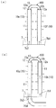
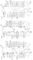
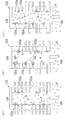
- FIG. 4 is the schematic diagram which showed the whole structure in the filtration process of the backwashing type
- FIG. 5 (a) is a schematic diagram which shows the distribution direction of the fluid in the filtration process by the filter element structure 100 of this embodiment.
- FIG. 6 is a schematic diagram for explaining the filtration process by the filter element structure 100 of the present embodiment, and (a) is a schematic diagram showing the filter element structure 100 and the fluid immediately after the filtration process is started.
- (B) is the schematic diagram which showed the filter element structure 100 and fluid of the state which the predetermined time passed after starting the filtration process. 5 and 6 are simplified for convenience of explanation.
- the filter element structure 100 is configured to perform a filtration process when the backwash arm 20 is not connected to the filter inlet 19 formed at the lower end thereof. In the example shown in FIGS. 4 and 5 (a), the filter element structure 100 is not connected to the backwash arm 20, and performs a fluid filtration process.
- the pair of filter elements 10e and 10f constituting the filter element structure 100 are fluids flowing from the apparatus inlet 4 in a state where the filter inlet 19 and the backwash arm 20 are not connected ( A fluid containing a filtration object (attachment) d such as dust flows from each filter inlet 19 into the cylinder of each filter medium 11 (see FIG. 6A).
- a fluid containing a filtration object (attachment) d such as dust flows from each filter inlet 19 into the cylinder of each filter medium 11 (see FIG. 6A).
- the inflowing fluid flows out into the connection pipes 13 connected to the upper holes 12 a of the upper lid portions 12.
- the connection pipe 13 is filled with the fluid that flows in, and the flow of fluid into the connection pipe 13 stops. As a result, it becomes the same state as each upper hole 12a of each upper cover part 12 being watertightly closed.
- each filter medium 11 passes from the inside to the outside of each filter medium 11 and flows out to each outer side of the pair of filter elements 10e and 10f.
- the filtering object d such as dust contained in the fluid is captured by the filter medium 11, and the filtering object d is removed from the fluid that has passed through the pair of filter elements 10e and 10f (FIG. 6B). reference).
- the filtered fluid that has passed through the pair of filter elements 10e, 10f flows through the outlet side area A2, and is discharged from the apparatus outlet 5.
- the upper lids 12 of the pair of filter elements 10e and 10f are provided with the upper holes 12a, respectively.
- the upper holes 12a are closed in a watertight manner. As a result, the same filtration performance as that of the conventional filter element is realized.
- FIG. 5B is a schematic diagram showing the flow direction of the fluid during the backwashing process by the filter element structure 100 of the present embodiment.
- FIG. 7 is a schematic diagram for explaining the backwashing process of the filter element structure 100 of the present embodiment.
- FIG. 7A is a schematic diagram showing the filter element structure 100 and the fluid immediately after the backwash process is started.
- (b) is a schematic diagram showing the filter element structure 100 and the fluid in a state in which a predetermined time has elapsed since the start of the backwash process, and (c) after washing away the dust by the backwash process, It is the schematic diagram which showed the state which started the filtration process again.
- the filter element structure 100 backwash processes are performed.
- the filter medium 11 connected to the backwash arm 20 is backwashed by the pair of filter elements 10 g and 10 h. 7 (a) and 7 (b), the backwash arm 20 communicating with the filter inlet 19 is omitted.
- the fluid flowing in the inlet side area A1 flows from the filter inlet 19 of the filter element 10h, and the flowing fluid flows out to the connecting pipe 13 connected to the upper hole 12a of the upper lid portion 12. Then, the fluid passes through the connection pipe 13 and flows out into the filter element 10g connected to the filter element 10h via the connection pipe 13. As a result, a large flow rate of fluid flows from the upper hole 12a of the upper lid 12 to which the connecting pipe 13 is connected toward the filter inlet 19, thereby adhering between the filter media 11 above the filter media 11 of the filter element 10g. The kimono (object to be filtered) d is washed away.
- the backwashing process when the backwash arm 20 is connected to the filter element 10g has been described.
- the fluid is filtered by the filter element 10g.
- the fluid flowing in from the filter inlet 19 passes through the connection pipe 13 and flows out into the filter element 10h connected to the filter element 10g via the connection pipe 13.
- the adhering matter (filtering) adhered between the filter media 11 above the filter media 11 of the filter element 10h.
- the object d) is washed away.
- the filter element structure 100 of the present embodiment employs a configuration in which a pair of filter elements 10 are connected via the connection pipe 13.
- the cleaning effect of the adhering substance d adhering to the filter element 10 (the cleaning effect by backwashing) can be enhanced, and the decrease in the filtration flow rate due to use is suppressed.
- this embodiment suppresses a decrease in the filtration flow rate by a configuration in which the pair of filter elements 10 are connected via the “connection pipe 13” (a configuration in which the number of parts is small and complicated control is not required). ing. That is, in the present embodiment, it is not necessary to newly provide an external power source, a control circuit, or the like in order to operate the above-described configuration (connection pipe 13) that enhances the cleaning effect. A pair of filter elements 10 that can suppress a decrease in flow rate are realized.
- a pair of filter elements 10 are connected via a connecting pipe 13.
- a connecting pipe 13 With this configuration, when backwashing is not performed, a state similar to the state in which the upper hole 12a of the upper lid 12 is closed can be obtained. As a result, the fluid is prevented from flowing out of the filter element 10 without passing through the filter medium 11 in the filtration step.
- the connecting pipe 13 of the present embodiment is U-shaped, but may be any shape as long as it can pass without hindering the flow of fluid.
Landscapes
- Chemical & Material Sciences (AREA)
- Chemical Kinetics & Catalysis (AREA)
- Filtering Of Dispersed Particles In Gases (AREA)
- Filtration Of Liquid (AREA)
Priority Applications (5)
| Application Number | Priority Date | Filing Date | Title |
|---|---|---|---|
| US14/423,823 US20150328569A1 (en) | 2012-08-28 | 2013-05-28 | Filter element structure and backwash type filter including the same filter element structure |
| EP13832001.5A EP2891512B1 (en) | 2012-08-28 | 2013-05-28 | Reverse-washing-type filtration device provided with a filter element structure |
| KR20157005881A KR20150046091A (ko) | 2012-08-28 | 2013-05-28 | 필터 요소 구조 및 이를 포함하는 역세정 타입 여과 장치 |
| CN201380044241.XA CN104661721B (zh) | 2012-08-28 | 2013-05-28 | 过滤元件构造以及具备该过滤元件构造的逆洗型过滤装置 |
| IN279KON2015 IN2015KN00279A (enExample) | 2012-08-28 | 2013-05-28 |
Applications Claiming Priority (2)
| Application Number | Priority Date | Filing Date | Title |
|---|---|---|---|
| JP2012187493A JP5967818B2 (ja) | 2012-08-28 | 2012-08-28 | フィルタエレメント構造及び当該フィルタエレメント構造を備えた逆洗型ろ過装置 |
| JP2012-187493 | 2012-08-28 |
Publications (1)
| Publication Number | Publication Date |
|---|---|
| WO2014034204A1 true WO2014034204A1 (ja) | 2014-03-06 |
Family
ID=50183029
Family Applications (1)
| Application Number | Title | Priority Date | Filing Date |
|---|---|---|---|
| PCT/JP2013/064726 Ceased WO2014034204A1 (ja) | 2012-08-28 | 2013-05-28 | フィルタエレメント構造及び当該フィルタエレメント構造を備えた逆洗型ろ過装置 |
Country Status (8)
| Country | Link |
|---|---|
| US (1) | US20150328569A1 (enExample) |
| EP (1) | EP2891512B1 (enExample) |
| JP (1) | JP5967818B2 (enExample) |
| KR (1) | KR20150046091A (enExample) |
| CN (1) | CN104661721B (enExample) |
| IN (1) | IN2015KN00279A (enExample) |
| TW (1) | TWI569862B (enExample) |
| WO (1) | WO2014034204A1 (enExample) |
Families Citing this family (7)
| Publication number | Priority date | Publication date | Assignee | Title |
|---|---|---|---|---|
| KR101629335B1 (ko) * | 2014-10-24 | 2016-06-13 | (주) 코리아 인바이텍 | 측면모터를 이용하여 수밀성을 향상시킨 용수여과장치 |
| KR101630778B1 (ko) * | 2015-03-25 | 2016-06-16 | 전준성 | 금형기용 오염수 여과기 |
| JP6059283B2 (ja) * | 2015-04-20 | 2017-01-11 | 富士フィルター工業株式会社 | 濾過ユニット |
| JP6659233B2 (ja) * | 2015-04-22 | 2020-03-04 | ヤマシンフィルタ株式会社 | フィルタエレメント及びフィルタ装置 |
| DE102017004661A1 (de) * | 2017-05-08 | 2018-11-08 | Hydac Process Technology Gmbh | Filtervorrichtung |
| KR101853898B1 (ko) * | 2018-03-12 | 2018-05-02 | 권영준 | 선박 평형수 필터장치 |
| US11612837B2 (en) * | 2020-09-18 | 2023-03-28 | Pall Corporation | Filter with interconnected hollow elements and method of use |
Citations (6)
| Publication number | Priority date | Publication date | Assignee | Title |
|---|---|---|---|---|
| JPS57209616A (en) * | 1981-06-19 | 1982-12-23 | Nippon Dyeing Mach Mfg Co Ltd | Automatic backwashing type strainer |
| JPS5997708U (ja) * | 1983-10-18 | 1984-07-02 | 日本染色機械株式会社 | 自動逆洗式ストレ−ナ− |
| JPS63267409A (ja) * | 1987-02-20 | 1988-11-04 | ザルトリウス・ゲゼルシヤフト・ミツト・ベシユレンクテル・ハフツング | 流体内容物を分離するための集成フイルターおよびフイルターケーシング |
| JPH01184005A (ja) * | 1988-01-18 | 1989-07-21 | Ngk Insulators Ltd | 複層フイルタの濾過膜形成装置 |
| JP2001170416A (ja) | 1999-12-20 | 2001-06-26 | Kanagawa Kiki Kogyo Kk | 逆洗型ろ過機 |
| JP2001232113A (ja) * | 2000-02-25 | 2001-08-28 | Kikkoman Corp | 濾過装置 |
Family Cites Families (11)
| Publication number | Priority date | Publication date | Assignee | Title |
|---|---|---|---|---|
| CH264591A (fr) * | 1946-12-14 | 1949-10-31 | Vilain Louis | Filtre continu sous pression. |
| US3318452A (en) * | 1966-02-01 | 1967-05-09 | Renard P Adams | Backwash means for an open ended multiple tube filter assembly |
| US3939075A (en) * | 1970-10-19 | 1976-02-17 | The Bauer Bros. Co. | Thickening apparatus |
| US4115276A (en) * | 1977-04-04 | 1978-09-19 | Purex Corporation | Multi-port backwash valve |
| EP0245585B1 (en) * | 1986-03-12 | 1990-06-27 | Sapporo Breweries Limited | A filtration apparatus |
| DE4345412C2 (de) * | 1993-11-26 | 1999-11-11 | Boll & Kirch Filter | Filterkerze |
| FI110483B (fi) * | 1999-09-20 | 2003-02-14 | Parker Hannifin Oy | Suodatuslaitteisto |
| FI104958B (fi) * | 1998-09-30 | 2000-05-15 | Parker Hannifin Oy | Jatkuvatoiminen suodatusmenetelmä ja -laitteisto |
| DE10024402C2 (de) * | 2000-05-19 | 2002-03-07 | Boll & Kirch Filter | Rückspülfilter, insbesondere für die Wasserfilterung und Verfahren zu deren Rückspülung |
| DE102007054737A1 (de) * | 2007-11-16 | 2009-05-20 | Hydac Process Technology Gmbh | Filtervorrichtung |
| CN202128974U (zh) * | 2011-07-11 | 2012-02-01 | 无锡市华尔泰机械制造有限公司 | 全自动滤水器 |
-
2012
- 2012-08-28 JP JP2012187493A patent/JP5967818B2/ja active Active
-
2013
- 2013-05-28 CN CN201380044241.XA patent/CN104661721B/zh active Active
- 2013-05-28 KR KR20157005881A patent/KR20150046091A/ko not_active Ceased
- 2013-05-28 EP EP13832001.5A patent/EP2891512B1/en active Active
- 2013-05-28 US US14/423,823 patent/US20150328569A1/en not_active Abandoned
- 2013-05-28 IN IN279KON2015 patent/IN2015KN00279A/en unknown
- 2013-05-28 WO PCT/JP2013/064726 patent/WO2014034204A1/ja not_active Ceased
- 2013-06-13 TW TW102120881A patent/TWI569862B/zh active
Patent Citations (6)
| Publication number | Priority date | Publication date | Assignee | Title |
|---|---|---|---|---|
| JPS57209616A (en) * | 1981-06-19 | 1982-12-23 | Nippon Dyeing Mach Mfg Co Ltd | Automatic backwashing type strainer |
| JPS5997708U (ja) * | 1983-10-18 | 1984-07-02 | 日本染色機械株式会社 | 自動逆洗式ストレ−ナ− |
| JPS63267409A (ja) * | 1987-02-20 | 1988-11-04 | ザルトリウス・ゲゼルシヤフト・ミツト・ベシユレンクテル・ハフツング | 流体内容物を分離するための集成フイルターおよびフイルターケーシング |
| JPH01184005A (ja) * | 1988-01-18 | 1989-07-21 | Ngk Insulators Ltd | 複層フイルタの濾過膜形成装置 |
| JP2001170416A (ja) | 1999-12-20 | 2001-06-26 | Kanagawa Kiki Kogyo Kk | 逆洗型ろ過機 |
| JP2001232113A (ja) * | 2000-02-25 | 2001-08-28 | Kikkoman Corp | 濾過装置 |
Non-Patent Citations (1)
| Title |
|---|
| See also references of EP2891512A4 |
Also Published As
| Publication number | Publication date |
|---|---|
| KR20150046091A (ko) | 2015-04-29 |
| JP5967818B2 (ja) | 2016-08-10 |
| US20150328569A1 (en) | 2015-11-19 |
| TW201417868A (zh) | 2014-05-16 |
| CN104661721B (zh) | 2016-07-06 |
| JP2014042888A (ja) | 2014-03-13 |
| CN104661721A (zh) | 2015-05-27 |
| EP2891512B1 (en) | 2020-07-08 |
| TWI569862B (zh) | 2017-02-11 |
| EP2891512A1 (en) | 2015-07-08 |
| IN2015KN00279A (enExample) | 2015-06-12 |
| EP2891512A4 (en) | 2016-06-15 |
Similar Documents
| Publication | Publication Date | Title |
|---|---|---|
| JP5967816B2 (ja) | フィルタエレメント及び当該フィルタエレメントを備えた逆洗型ろ過装置 | |
| JP5967818B2 (ja) | フィルタエレメント構造及び当該フィルタエレメント構造を備えた逆洗型ろ過装置 | |
| US10525384B2 (en) | Filter element and filtering apparatus | |
| US10918980B2 (en) | Filtering apparatus | |
| KR101991116B1 (ko) | 필터 장치 | |
| KR101254776B1 (ko) | 가압시스템을 갖춘 선박 평형수 필터장치 | |
| JP5024802B2 (ja) | フィルタ装置 | |
| JPH0360705A (ja) | 液体からの固形物および浮遊物の濾過装置 | |
| CN103561837B (zh) | 过滤设备 | |
| US3318452A (en) | Backwash means for an open ended multiple tube filter assembly | |
| CN106457260A (zh) | 磁性过滤器及磁性物质除去方法 | |
| JP2010521303A5 (enExample) | ||
| JP2014512953A5 (enExample) | ||
| WO2017010144A1 (ja) | フィルタエレメント、逆洗型ろ過装置、及びフィルタエレメントのろ過方法及び逆洗方法 | |
| WO2020116009A1 (ja) | 逆洗型ろ過装置用のフィルタエレメント及び逆洗型ろ過装置 | |
| JP2022132669A (ja) | ろ過装置 | |
| JP3137987U (ja) | 逆洗型ろ過装置 | |
| JP2001170416A (ja) | 逆洗型ろ過機 | |
| JP6140123B2 (ja) | ストレーナ | |
| JP6432000B1 (ja) | 油圧モータ及び逆洗型ろ過装置 | |
| JP6964866B2 (ja) | 連続ろ過装置 | |
| CN119504010B (zh) | 一种生物滤池净化水装置 | |
| KR20190008430A (ko) | 웨이퍼로부터 포토레지스트를 제거할 때의 액체 필터링 | |
| JP5299784B2 (ja) | リーフフィルタの軸シール装置と方法 | |
| JP2005169183A (ja) | 液体濾過装置および切換弁 |
Legal Events
| Date | Code | Title | Description |
|---|---|---|---|
| 121 | Ep: the epo has been informed by wipo that ep was designated in this application |
Ref document number: 13832001 Country of ref document: EP Kind code of ref document: A1 |
|
| WWE | Wipo information: entry into national phase |
Ref document number: 14423823 Country of ref document: US |
|
| NENP | Non-entry into the national phase |
Ref country code: DE |
|
| ENP | Entry into the national phase |
Ref document number: 20157005881 Country of ref document: KR Kind code of ref document: A |
|
| WWE | Wipo information: entry into national phase |
Ref document number: 2013832001 Country of ref document: EP |