WO2014030260A1 - リチウムイオン二次電池用負極およびその製造方法 - Google Patents
リチウムイオン二次電池用負極およびその製造方法 Download PDFInfo
- Publication number
- WO2014030260A1 WO2014030260A1 PCT/JP2012/071491 JP2012071491W WO2014030260A1 WO 2014030260 A1 WO2014030260 A1 WO 2014030260A1 JP 2012071491 W JP2012071491 W JP 2012071491W WO 2014030260 A1 WO2014030260 A1 WO 2014030260A1
- Authority
- WO
- WIPO (PCT)
- Prior art keywords
- negative electrode
- active material
- material layer
- lithium ion
- ion secondary
- Prior art date
- Legal status (The legal status is an assumption and is not a legal conclusion. Google has not performed a legal analysis and makes no representation as to the accuracy of the status listed.)
- Ceased
Links
Images

Classifications
-
- H—ELECTRICITY
- H01—ELECTRIC ELEMENTS
- H01M—PROCESSES OR MEANS, e.g. BATTERIES, FOR THE DIRECT CONVERSION OF CHEMICAL ENERGY INTO ELECTRICAL ENERGY
- H01M10/00—Secondary cells; Manufacture thereof
- H01M10/05—Accumulators with non-aqueous electrolyte
- H01M10/052—Li-accumulators
- H01M10/0525—Rocking-chair batteries, i.e. batteries with lithium insertion or intercalation in both electrodes; Lithium-ion batteries
-
- H—ELECTRICITY
- H01—ELECTRIC ELEMENTS
- H01M—PROCESSES OR MEANS, e.g. BATTERIES, FOR THE DIRECT CONVERSION OF CHEMICAL ENERGY INTO ELECTRICAL ENERGY
- H01M4/00—Electrodes
- H01M4/02—Electrodes composed of, or comprising, active material
- H01M4/13—Electrodes for accumulators with non-aqueous electrolyte, e.g. for lithium-accumulators; Processes of manufacture thereof
- H01M4/133—Electrodes based on carbonaceous material, e.g. graphite-intercalation compounds or CFx
-
- H—ELECTRICITY
- H01—ELECTRIC ELEMENTS
- H01M—PROCESSES OR MEANS, e.g. BATTERIES, FOR THE DIRECT CONVERSION OF CHEMICAL ENERGY INTO ELECTRICAL ENERGY
- H01M4/00—Electrodes
- H01M4/02—Electrodes composed of, or comprising, active material
- H01M4/13—Electrodes for accumulators with non-aqueous electrolyte, e.g. for lithium-accumulators; Processes of manufacture thereof
- H01M4/139—Processes of manufacture
- H01M4/1393—Processes of manufacture of electrodes based on carbonaceous material, e.g. graphite-intercalation compounds or CFx
-
- H—ELECTRICITY
- H01—ELECTRIC ELEMENTS
- H01M—PROCESSES OR MEANS, e.g. BATTERIES, FOR THE DIRECT CONVERSION OF CHEMICAL ENERGY INTO ELECTRICAL ENERGY
- H01M4/00—Electrodes
- H01M4/02—Electrodes composed of, or comprising, active material
- H01M4/36—Selection of substances as active materials, active masses, active liquids
- H01M4/58—Selection of substances as active materials, active masses, active liquids of inorganic compounds other than oxides or hydroxides, e.g. sulfides, selenides, tellurides, halogenides or LiCoFy; of polyanionic structures, e.g. phosphates, silicates or borates
- H01M4/583—Carbonaceous material, e.g. graphite-intercalation compounds or CFx
- H01M4/587—Carbonaceous material, e.g. graphite-intercalation compounds or CFx for inserting or intercalating light metals
-
- Y—GENERAL TAGGING OF NEW TECHNOLOGICAL DEVELOPMENTS; GENERAL TAGGING OF CROSS-SECTIONAL TECHNOLOGIES SPANNING OVER SEVERAL SECTIONS OF THE IPC; TECHNICAL SUBJECTS COVERED BY FORMER USPC CROSS-REFERENCE ART COLLECTIONS [XRACs] AND DIGESTS
- Y02—TECHNOLOGIES OR APPLICATIONS FOR MITIGATION OR ADAPTATION AGAINST CLIMATE CHANGE
- Y02E—REDUCTION OF GREENHOUSE GAS [GHG] EMISSIONS, RELATED TO ENERGY GENERATION, TRANSMISSION OR DISTRIBUTION
- Y02E60/00—Enabling technologies; Technologies with a potential or indirect contribution to GHG emissions mitigation
- Y02E60/10—Energy storage using batteries
-
- Y—GENERAL TAGGING OF NEW TECHNOLOGICAL DEVELOPMENTS; GENERAL TAGGING OF CROSS-SECTIONAL TECHNOLOGIES SPANNING OVER SEVERAL SECTIONS OF THE IPC; TECHNICAL SUBJECTS COVERED BY FORMER USPC CROSS-REFERENCE ART COLLECTIONS [XRACs] AND DIGESTS
- Y02—TECHNOLOGIES OR APPLICATIONS FOR MITIGATION OR ADAPTATION AGAINST CLIMATE CHANGE
- Y02P—CLIMATE CHANGE MITIGATION TECHNOLOGIES IN THE PRODUCTION OR PROCESSING OF GOODS
- Y02P70/00—Climate change mitigation technologies in the production process for final industrial or consumer products
- Y02P70/50—Manufacturing or production processes characterised by the final manufactured product
Definitions
- the present invention relates to a negative electrode used for a lithium ion secondary battery, and a method of manufacturing the same.
- Lithium ion secondary batteries which are non-aqueous secondary batteries, have a high energy density compared to nickel cadmium secondary batteries and nickel hydrogen secondary batteries, and thus are widely used as power sources for notebook computers and mobile phones. Further, with the development of electric vehicles and hybrid vehicles as environmentally friendly vehicles, the application of lithium ion secondary batteries to power sources for vehicles is being studied.
- graphite also has a low charge potential, which is close to the deposition potential of lithium metal. Therefore, during charging at a low temperature of 0 ° C. or lower assumed for automotive applications, the potential of the negative electrode is further lowered by the overvoltage, and lithium metal is likely to be deposited. Deposition of lithium metal in the negative electrode is not preferable because it lowers the battery capacity.
- Patent Document 2 describes a method of suppressing a decrease in the negative electrode potential by setting the charge voltage of the battery low when the temperature decreases. There is.
- An object of the present invention is to provide a negative electrode for a lithium ion secondary battery in which lithium metal is not easily deposited during low temperature charging, and a method for producing the same.
- the inventors of the present invention as a result of intensive studies, have found that lithium metal deposition causes the lithium ion conduction resistance to increase during low temperature charging, and charge current is concentrated on the surface of the negative electrode (the surface facing the positive electrode is called surface). I found that it was the cause. Based on this finding, it has been found that providing a lithium ion conduction path leading from the surface of the negative electrode to the interior works effectively to suppress the deposition of lithium metal.
- the negative electrode for a lithium ion secondary battery of the present invention is a negative electrode for a lithium ion secondary battery having a current collector and an active material layer formed on the current collector, and the active material layer is Graphite is used as an active material, and the average line of the roughness curve obtained by measuring the surface roughness of the active material layer is 10 ⁇ m inward from the surface of the active material layer, and the sum of cut lengths cut by a parallel-shifted line It is characterized in that a load length ratio (Rmr (10 ⁇ m)), which represents a ratio of the ratio to the reference length in percentage, is 50% or more and 98.5% or less.
- the electrode group is configured by overlapping and winding with a positive electrode via a separator, and the load length ratio (Rmr (10 ⁇ m) is closer to the winding end than to the winding start of the negative electrode. It is preferred that)) be small.
- the load length ratio (Rmr (10 ⁇ m)) of the positive electrode facing portion facing the positive electrode is 50% to 98.5%. Is preferred.
- the method for producing a negative electrode for a lithium ion secondary battery of the present invention is a method for producing a negative electrode for a lithium ion secondary battery in which an active material layer is formed on a current collector, and the surface of the active material layer is Of the roughness curve obtained by measuring the surface roughness of the active material layer by 10 ⁇ m from the surface of the active material layer inwards, relative to the reference length of the sum of the cutting lengths cut by parallel-displaced lines It is characterized in that the load length ratio (Rmr (10 ⁇ m)), in which the ratio is expressed in percentage, includes a surface roughening step in which the surface roughness is 50% or more and 98.5% or less.
- FIG. 7 is a view showing an example of a method of manufacturing a negative electrode according to the present embodiment.
- FIG. 7 is a view showing an example of a method of manufacturing a negative electrode according to the present embodiment.
- the schematic diagram which shows an example of the lithium ion secondary battery which concerns on a present Example in a cross section.
- the fragmentary sectional view which shows another example of the lithium ion secondary battery which concerns on a present Example.
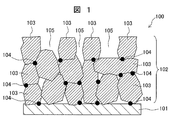
- FIG. 1 is an enlarged view of a cross section of a negative electrode of a lithium ion secondary battery containing graphite according to the present example.
- the lithium ion secondary battery which is a non-aqueous secondary battery, includes the negative electrode 100.
- the negative electrode 100 includes a current collector foil 101 and an active material layer 102 formed in a layer on the current collector foil 101.
- the active material layer 102 contains graphite 103 as an active material.
- the graphite 103 of the active material layer 102 is bound to each other between particles of each other by the binding agent 104 and to the surface of the current collector foil 101.
- a lithium ion conduction path 105 communicating with the inside of the active material layer 102 is provided.
- lithium ions can easily reach the inside of the active material layer 102 even at low temperature charging, and concentration of the charging current on the surface of the active material layer 102 can be suppressed. Therefore, precipitation of lithium metal at the time of low temperature charge can be suppressed.
- the lithium ion conduction path 105 can be evaluated by the load length ratio (Rmr (C)) of the roughness curve measured according to JIS B0601.
- the calculation method of load length ratio Rmr (C) which concerns on a present Example is shown in FIG. From the average line of the roughness curve (the line drawn so that the area of the convex portion present above in the roughness curve and the area of the recess present below it are equal) from the inner side toward the negative electrode A distance is defined as a cutting level C, and a ratio of a sum of cutting lengths M i cut at a cutting line parallel to the average line at the cutting level C to a reference length l is expressed as a percentage of the load length ratio Rmr (C And).
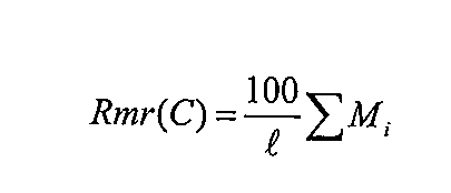
- the load length ratio Rmr (C) of the roughness curve is expressed by the following equation.
- Rmr (10 ⁇ m) is preferably 98.5% or less, and more preferably Rmr (12 ⁇ m) is 99.3% or less. More preferably, Rmr (10 ⁇ m) should be 95.6% or less, and further Rmr (12 ⁇ m) should be 97.5% or less. In each case, Rmr should be 50% or more. When Rmr is smaller than 50%, the amount of graphite in the active material layer 102 which is the surface layer of the negative electrode is reduced, the capacity is reduced, and the strength of the active material layer 102 is reduced.
- Graphite 103 is a carbon material in which a graphite structure has developed, and natural graphite, artificially produced artificial graphite, graphitized carbon fiber, and the like can be used.
- the particle diameter of the graphite 103 is not particularly limited, but may be about 1 to 50 ⁇ m. Further, the surface of the graphite 103 may be coated with another material, low crystalline carbon or the like.
- binding agent 104 is not particularly limited, for example, polyethylene, polypropylene, polytetrafluoroethylene, polyvinylidene fluoride, styrene butadiene rubber, and the like can be used.
- the active material layer 102 of the negative electrode 100 may contain a conductive aid.
- a conductive aid for example, carbon black, carbon fiber, metal fiber, or conductive polymer can be used.
- the active material layer 102 of the negative electrode 100 may contain an active material other than the graphite 103. Examples of the active material other than the graphite 103 include silicon, tin, aluminum, antimony, lithium titanate and the like.
- the density of the active material layer 102 is preferably 1.0 g / cm 3 or more by a press or the like. If the value is lower than this range, the amount of graphite 103 contained per unit volume decreases, and the energy density decreases, which is not preferable. In addition, a more preferable density is 1.2 g / cm 3 or more.
- the upper limit of the density of the active material layer 102 is preferably 2.2 g / cm 3 because the true density of the graphite 103 is 2.2 g / cm 3 .
- the density of the active material layer 102 can be calculated from the thickness and weight.
- the thickness and weight per unit area of the negative electrode 100 are measured together with the current collector foil 101, and then the active material layer 102 is removed from the current collector foil 101 using a solvent or the like, and then the current collector foil is collected.
- the thickness and the weight per unit area of the active material layer 102 alone can be obtained by measuring the thickness and the weight per unit area 101 and subtracting the weight from the previously measured result.
- the density can be determined by dividing the weight per unit area of the active material layer 102 by the volume of the negative electrode 100 obtained from the thickness of the negative electrode 100 and the unit area.
- the thickness of the active material layer 102 is not particularly limited, but is preferably 20 to 200 ⁇ m, and more preferably 50 to 150 ⁇ m. If the thickness of the active material layer 102 is too thin, the amount of graphite per unit electrode area decreases, and the capacity is undesirably reduced. In addition, when the thickness of the active material layer 102 is too large, it is not preferable because lithium ions hardly reach the graphite in the vicinity of the current collector foil 101 even if the lithium ion conduction path 105 is provided in the active material layer 102.
- the current collector foil 101 of the negative electrode 100 is not particularly limited as long as it is difficult to deteriorate in the battery and has electron conductivity, and copper, nickel, stainless steel or the like can be used. Among them, copper is preferably used.
- the thickness of the current collector foil 101 of the negative electrode 100 is not particularly limited, but a thickness of 1 to 100 ⁇ m can be used. In addition, if the strength and electron conductivity of the negative electrode 100 itself are sufficient, it is not necessary to use a current collector foil.
- the surface of the active material layer 102 is processed, and the average line of the roughness curve obtained by measuring the surface roughness of the active material layer 102 is taken from the surface of the active material layer 102
- the load length ratio (Rmr (10 ⁇ m)) which represents the ratio of the sum of cutting lengths cut by a parallel-displaced line to the reference length by 10 ⁇ m in the direction, as 50% to 98.5% Forming a lithium ion conduction path.
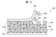
- the method of processing the surface of the active material layer 102 is not particularly limited, for example, as shown in FIG. 3, a step of sticking an adhesive tape 301 on the surface of the active material layer 102 of the negative electrode 100; The process of peeling off the adhesive tape 301 and peeling the graphite 302 of a part of active material layer with the adhesive tape 301 from the surface of the active material layer 102 is included.
- the active material layer 102 of the negative electrode 100 is formed by applying a slurry-like active material mixture onto the surface of the current collector foil 101 and drying it, and then press-molding the active material layer.
- the surface 102 is smooth, and the surface side of the active material layer 102 has a higher density than the current collector foil 101 side. Therefore, a lithium ion conduction path communicating with the inside of the active material layer 102 can be formed by peeling off only part of the graphite from the surface with the adhesive tape 301.
- the adhesive tape 301 a carbon tape, a cellophane tape, a polyimide tape or the like can be used.
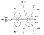
- the other manufacturing method of the negative electrode which concerns on FIG. 4 at a present Example is shown.
- active material layers 402 are provided on both sides of the current collector foil 401, and pressing between the pair of rollers 403 is performed to increase the density of the active material layer 402.
- the negative electrode 400 is further passed between the pair of rollers 405 covered with the adhesive tape 404, whereby part of the graphite on the surface of the active material layer 402 is exfoliated by the adhesive tape 404, to the inside of the active material layer 402.
- a lithium ion conduction path 105 is formed.
- the shape of the projection is preferably needle-like.
- a lithium ion conduction path communicating with the inside of the active material layer 402 is formed on the surface of the active material layer 402.
- the step of pressing a plate, a roller or the like having projections on the surface to the negative electrode surface may also serve as a pressing step of increasing the density of the negative electrode.
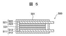
- FIG. 5 is a schematic view showing an example of the lithium ion secondary battery according to the present embodiment in cross section.
- the lithium ion secondary battery 500 has a negative electrode 511 and a positive electrode 521.
- a negative electrode active material layer 513 is provided on a negative electrode current collector foil 512
- a positive electrode active material layer 523 is provided on a positive electrode current collector foil 522.
- an electrode group in which the separator 531 is interposed between the negative electrode 511 and the positive electrode 521 and stacked one on another is accommodated in the insulating sealed case 501.
- the negative electrode current collector foil 512 and the positive electrode current collector foil 522 are taken out from the sealed case 501 and can output the potential difference generated between the negative electrode 511 and the positive electrode 521 to the outside.
- the inside of the sealed case 501 is filled with an electrolytic solution.
- the negative electrode 511 preferably has a load length ratio (Rmr (10 ⁇ m)) of the positive electrode facing portion facing the positive electrode 521 of 50% or more and 98.5% or less. According to lithium ion secondary battery 500 having the above configuration, in charge and discharge of the battery, negative electrode 511 contributes only to the facing portion of positive electrode 521, so the load length ratio of negative electrode 511 is a desired value only for the positive electrode facing portion. Also, sufficient effects can be obtained, and the manufacturing process can be simplified.
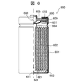
- FIG. 6 is a partial cross-sectional view showing another example of the lithium ion secondary battery according to the present example.
- the lithium ion secondary battery 600 is a cylindrical secondary battery in which a cylindrical electrode group 602 is accommodated in a bottomed cylindrical battery can 601.
- the electrode group 602 is configured by laminating and winding a negative electrode 621, a separator 631, and a positive electrode 611.
- the load length ratio (Rmr (10 ⁇ m)) is smaller on the winding end side than on the winding start side of the negative electrode 621.
- the temperature is lower on the winding end end side than on the winding start end side of the negative electrode 621. Therefore, lithium metal is more likely to be deposited at the time of low temperature charging on the winding end end side than on the winding start end side of the negative electrode 621. If the load length ratio (Rmr (10 ⁇ m)) is too small, the battery capacity may decrease. Therefore, the load length ratio (Rmr (10 ⁇ m)) on the winding end side of the negative electrode 621 susceptible to low temperature is decreased, and the load length ratio on the rolling start end side of the negative electrode 621 resistant to low temperature (Rmr (10 ⁇ m)) is increased.
- the load length ratio (Rmr (10 ⁇ m)) be smaller on the winding end end side than on the winding start end side of the negative electrode 621. Thereby, it is possible to suppress the deposition of lithium metal at the time of low temperature charging while suppressing the decrease in battery capacity.
- the negative electrode tab 603 is connected to the current collector foil of the negative electrode 621, and the positive electrode tab 604 is connected to the current collector foil of the positive electrode 611. Further, the negative electrode tab 603 is connected to the battery can 601, and the positive electrode tab 604 is connected to the battery lid 605. An insulating member 606 is interposed between the battery can 601 and the battery cover 605, and they are insulated from each other.
- the battery further includes an inner lid 607, an internal pressure opening valve 608, a gasket 609, and a PTC element 610.
- the inside of the battery can 601 is filled with an electrolyte that conducts lithium ions.
- the shape of the lithium ion secondary battery is not limited to the cylindrical one shown in FIG. 6, and may be square or laminated.
- the positive electrode active material is not particularly limited as long as it can occlude and release lithium ions.
- LiCoO 2 LiCo 0.33 Ni 0.33 Mn 0.33 O 2 , LiNiO 2 , LiMn 2 O 4 , LiNi 0.5 Mn 1.5 O 4 , LiFePO 4 , LiMnPO 4 , Li 2 FeSiO 4 or the like can be used.
- the current collector foil of the positive electrode is not particularly limited as long as it is difficult to deteriorate in the battery and has electron conductivity, and aluminum, titanium, stainless steel or the like can be used. Among them, aluminum is preferably used.
- the thickness of the current collector foil of the positive electrode is not particularly limited, but a thickness of 1 to 100 ⁇ m can be used. If the strength and electron conductivity of the negative electrode itself are sufficient, it is not necessary to use a current collector foil.
- an insulating porous material can be used for the separator.
- the material is not particularly limited, and, for example, polypropylene, polyethylene and the like can be used.
- a non-aqueous electrolytic solution composed of a non-aqueous solvent and a lithium salt dissolved in the solvent
- a non-aqueous solvent mixed solvents, such as propylene carbonate, ethylene carbonate, dimethyl carbonate, diethyl carbonate, dimethoxyethane, tetrahydrofuran, methyl acetate, etc. can be used, for example.
- the lithium salt lithium perchlorate, lithium hexafluorophosphate, lithium tetrafluoroborate, lithium trifluoride methanesulfonate, or the like can be used.
- vinylene carbonate, ethylene sulfite or the like may be added as an additive.
- a polymer gel electrolyte can be used instead of the non-aqueous electrolyte solution.
- the polymer gel electrolyte for example, polyethylene oxide, polymethyl methacrylate, polyacrylonitrile and the like can be used.
- Such an electrolytic solution (or a polymer gel electrolyte) has a large lithium ion conduction resistance at low temperature, so current concentrates on the negative electrode surface at the time of charge, and the potential drops locally. At this time, when graphite originally having a low charge potential is used, lithium metal is deposited, but the deposition can be suppressed by using the negative electrode according to this example.
- Example 1 Graphite and a binder were mixed, coated on a copper current collector foil, and pressed to make the density of the active material layer of the negative electrode 1.5 g / cm 3 . Thereafter, a cellophane tape, which is an adhesive tape, was attached to the surface of the active material layer and then peeled off, thereby peeling part of the graphite on the surface of the active material layer and providing a lithium ion conduction path on the surface of the active material layer. The negative electrode according to this example was obtained. Thereafter, the obtained negative electrode, separator and positive electrode were combined and incorporated into a sealed case, and an electrolytic solution was injected to obtain a test battery according to this example.
- a cellophane tape which is an adhesive tape
- Example 2 A negative electrode according to this example and a test battery were obtained in the same manner as in Example 1 except that a carbon tape was used instead of the cellophane tape as an adhesive tape for forming a lithium ion conduction path.
- Example 3 Graphite and a binder were mixed, coated on a copper current collector foil, and pressed to make the density of the active material layer of the negative electrode 1.5 g / cm 3 . Then, a part of the graphite on the surface of the active material layer was peeled off by sticking and peeling off the polyimide tape which is an adhesive tape on the surface of the active material layer, and a lithium ion conduction path was provided on the surface of the active material layer . Furthermore, the negative electrode which concerns on a present Example was obtained by pressing again to such an extent that the density of an active material layer does not change. Thereafter, the obtained negative electrode, separator and positive electrode were combined and incorporated into a sealed case, and an electrolytic solution was injected to obtain a test battery according to this example.
- Example 4 A negative electrode according to the present example and a test battery were obtained in the same manner as in Example 1 except that a polyimide tape was used instead of the cellophane tape as an adhesive tape for forming a lithium ion conduction path.
- the surface of the active material layer was smooth, and the path from the surface to the inside of the active material layer could not be confirmed. Therefore, the lithium ion conduction to the graphite inside the active material layer at the time of charge is borne by the electrolyte present in the small gap between the graphites on the surface side, so the lithium ion conduction resistance becomes large. I will.
- lithium ions hardly reach the graphite inside the active material layer, and the charge current is concentrated on the graphite on the surface of the active material layer It will Therefore, precipitation of lithium metal occurs.
- precipitation of lithium metal can be suppressed by setting the load length ratio Rmr to 98.5% or less, and precipitation of lithium metal can be mostly seen by setting it to 95.6% or less. It turned out that it disappeared.
- precipitation of lithium metal can be suppressed by setting the load length ratio Rmr to 99.3% or less, and precipitation of lithium metal is further suppressed by 97.5% or less. It turned out that it could not be seen.
- the cutting level of 1 ⁇ m and 20 ⁇ m no clear correlation was found between the value of the load length ratio Rmr and the amount of deposited lithium metal.
- the lithium ion conduction path may be provided such that the load length ratio Rmr at a cutting level of 10 ⁇ m is 98.5% or less, more preferably 95.6% or less.
- the load length ratio Rmr at a cutting level of 12 ⁇ m is preferably 99.3% or less, more preferably 97.5% or less.
- the present invention is not limited to the above-mentioned embodiment, and various designs are possible in the range which does not deviate from the spirit of the present invention described in the claim. It is possible to make changes.
- the above-described embodiment has been described in detail in order to explain the present invention in an easy-to-understand manner, and is not necessarily limited to one having all the described configurations.
- part of the configuration of one embodiment can be replaced with the configuration of another embodiment, and the configuration of another embodiment can be added to the configuration of one embodiment.
Landscapes
- Chemical & Material Sciences (AREA)
- Engineering & Computer Science (AREA)
- Chemical Kinetics & Catalysis (AREA)
- Electrochemistry (AREA)
- General Chemical & Material Sciences (AREA)
- Materials Engineering (AREA)
- Manufacturing & Machinery (AREA)
- Inorganic Chemistry (AREA)
- Battery Electrode And Active Subsutance (AREA)
- Secondary Cells (AREA)
Description
本発明は、リチウムイオン二次電池に用いられる負極、およびその製造方法に関する。
非水系二次電池であるリチウムイオン二次電池は、ニッケルカドミウム二次電池やニッケル水素二次電池に比べて高いエネルギー密度を有することから、ノートパソコン、携帯電話の電源として広く使用されている。また、環境に配慮した自動車として電気自動車およびハイブリッド自動車の開発が進む中、リチウムイオン二次電池は自動車用の電源への適用が検討されている。
リチウムイオン二次電池の負極において、リチウムイオンを可逆的に吸蔵、放出する活物質のひとつとして、特許文献1に示すように黒鉛が使われている。黒鉛は放電電位が低いので、負極活物質として用いることによって、高いエネルギー密度を有するリチウムイオン二次電池を得ることができる。
しかしながら、黒鉛は充電電位も低く、リチウム金属の析出電位に近い。そのため、自動車用途で想定されるような0℃以下の低温の充電時には、過電圧によって負極の電位が更に低下し、リチウム金属が析出しやすくなる。負極におけるリチウム金属の析出は、電池容量を低下させてしまうため、好ましくない。
こうした低温におけるリチウム金属の析出を抑制するために、特許文献2には、温度が低くなった際に、電池の充電電圧を低く設定することで、負極電位の低下を抑制する方法が記載されている。
しかしながら、特許文献2の方法では、低温時の充電量が少なくなるため、放電時に大きな容量を得ることができない。そのため、黒鉛を用いた負極において、低温充電時にリチウム金属の析出を抑制する本質的な方法が望まれている。
本発明の目的は、低温充電時にリチウム金属が析出しにくいリチウムイオン二次電池用負極及びその製造方法を提供することである。
本発明の発明者は、鋭意研究の結果、リチウム金属の析出は、低温充電時にリチウムイオンの伝導抵抗が大きくなり、負極の表面(正極と対向する面を表面と呼ぶ)に充電電流が集中することが原因であることを見出した。この知見に基づき、負極表面から内部へ通じるリチウムイオンの伝導経路を設けることが、リチウム金属の析出抑制に有効に働くことを見出した。
すなわち、本発明のリチウムイオン二次電池用負極は、集電体と、集電体の上に形成された活物質層とを有するリチウムイオン二次電池用負極であって、活物質層は、活物質として黒鉛を有し、活物質層の表面粗さ測定によって得られる粗さ曲線の平均線を活物質層の表面から内部方向へ10μm、平行移動させた線で切断した切断長さの和の基準長さに対する比を百分率で表した負荷長さ率(Rmr(10μm))が、50%以上、98.5%以下であることを特徴としている。
また、正極との間にセパレータを介して重ね合わされて捲回することによって電極群を構成し、負極の捲き始め端部側よりも捲き終わり端部側の方が負荷長さ率(Rmr(10μm))が小さいことが好ましい。
そして、正極との間にセパレータを介して重ね合わされて電極群を構成し、正極に対向する正極対向部の負荷長さ率(Rmr(10μm))が50%以上、98.5%以下であることが好ましい。
本発明のリチウムイオン二次電池用負極の製造方法は、集電体の上に活物質層が形成されたリチウムイオン二次電池用負極の製造方法であって、活物質層の表面を祖面化して、活物質層の表面粗さ測定によって得られる粗さ曲線の平均線を活物質層の表面から内部方向へ10μm、平行移動させた線で切断した切断長さの和の基準長さに対する比を百分率で表した負荷長さ率(Rmr(10μm))が、50%以上、98.5%以下の表面粗さとする表面荒らし工程を含むことを特徴としている。
本発明によって、黒鉛を活物質に用いた負極において、低温充電時にリチウム金属の析出を抑制できる。なお、上記した以外の課題、構成及び効果は、以下の実施形態の説明により明らかにされる。
以下に、本発明の実施の態様を示す。
図1は、本実施例に係る黒鉛を含むリチウムイオン二次電池の負極の断面を拡大して示す図である。
非水系二次電池であるリチウムイオン二次電池は、負極100を備えている。
負極100は、集電箔101と、集電箔101の上に層状に形成された活物質層102とを有している。活物質層102は、活物質として黒鉛103を含有している。活物質層102の黒鉛103は、結着剤104によって互いの粒子間、及び集電箔101の表面に結着されている。
活物質層102の表面には、活物質層102の内部に通じるリチウムイオン伝導経路105が設けられている。このような構成とすることで、低温充電時においてもリチウムイオンが活物質層102の内部まで容易に達することができ、活物質層102の表面に充電電流が集中することを抑制できる。したがって、低温充電時におけるリチウム金属の析出を抑制することができる。
リチウムイオン伝導経路105は、JIS B0601に準拠して測定される粗さ曲線の負荷長さ率(Rmr(C))で評価することができる。本実施例に係る負荷長さ率Rmr(C)の算出方法を図2に示す。粗さ曲線の平均線(粗さ曲線において、それよりも上方に存在する凸部の面積と、それよりも下方に存在する凹部の面積が等しくなるように引いた線)から負極内部方向への距離を切断レベルCと定義し、切断レベルCにおける平均線との平行線で切断した切断長さMiの和の基準長さlに対する比を百分率で表したものを負荷長さ率Rmr(C)とする。粗さ曲線の負荷長さ率Rmr(C)は、下記の式で表される。
リチウム金属の析出を抑制するためには、Rmr(10μm)を98.5%以下とすることが好ましく、更に、Rmr(12μm)を99.3%以下とすることが好ましい。また、より好ましくは、Rmr(10μm)を95.6%以下とすること良く、更に、Rmr(12μm)を97.5%以下とすることが良い。また、いずれの場合においてもRmrは50%以上とすることが良い。Rmrを50%よりも小さくすると、負極表層である活物質層102の黒鉛の量が少なくなり容量が低下するとともに、活物質層102の強度が低下するため好ましくない。
黒鉛103は、グラファイト構造が発達した炭素材料であり、天然黒鉛や人工的に作られた人造黒鉛、黒鉛化炭素繊維などを用いることができる。黒鉛103の粒子径は特に限定されるものではないが、1~50μm程度のものを用いることができる。また、黒鉛103の表面は他の材料や低結晶性の炭素などで被覆されていても良い。
結着剤104は、特に限定されるものではないが、例えば、ポリエチレン、ポリプロピレン、ポリテトラフルオロエチレン、ポリフッ化ビニリデン、スチレンブタジエンゴムなどを用いることができる。
また、負極100の活物質層102には、黒鉛103、結着剤104の他に、導電助材が含まれていても良い。導電助材は、例えば、カーボンブラック、炭素繊維、金属繊維、あるいは導電性ポリマーを用いることができる。負極100の活物質層102には、黒鉛103以外の活物質が含まれていても良い。黒鉛103以外の活物質としては、例えば、シリコン、スズ、アルミニウム、アンチモン、チタン酸リチウムなどが挙げられる。
活物質層102の密度は、プレスなどによって、1.0g/cm3以上とすることが好ましい。これよりも低い値であると、単位体積あたりに含まれる黒鉛103の量が少なくなるため、エネルギー密度が小さくなり、好ましくない。なお、より好ましい密度は1.2g/cm3以上である。そして、活物質層102の密度の上限は、黒鉛103の真密度が2.2g/cm3であることから、2.2g/cm3とすることが好ましい。活物質層102の密度は、厚さと重さから算出することができる。例えば、負極100の厚さと単位面積あたりの重さを集電箔101ごと測定しておき、その後、集電箔101から活物質層102を、溶剤などを用いて除去してから、集電箔101の厚さと単位面積あたりの重さを測定し、先に測定した結果から差し引くことで、活物質層102のみの厚さと単位面積あたりの重さを得ることができる。次に、活物質層102の単位面積あたりの重さを、負極100の厚さと単位面積から求めた負極100の体積で除することで、密度を求めることができる。
また、活物質層102の厚さは特に限定されるものではないが、20~200μmとすることが好ましく、50~150μmとすることがより好ましい。活物質層102の厚さを薄くしすぎると単位電極面積あたりの黒鉛の量が少なくなるため、容量が低下してしまい、好ましくない。また、活物質層102の厚さを厚くしすぎると、活物質層102にリチウムイオン伝導経路105を設けても、集電箔101近傍の黒鉛にリチウムイオンが到達しにくくなるため、好ましくない。
負極100の集電箔101は、電池内で変質しにくく、電子伝導性を有するものであれば特に限定されるものではないが、銅、ニッケル、ステンレスなどを用いることができる。なかでも、銅を用いることが好ましい。負極100の集電箔101の厚さは、特に限定されるものではないが1~100μmのものを用いることができる。また、負極100自体の強度と電子伝導性が十分であれば、必ずしも集電箔を用いる必要はない。
本実施例に係る負極100の製造方法は、活物質層102の表面を加工して、活物質層102の表面粗さ測定によって得られる粗さ曲線の平均線を活物質層102の表面から内部方向へ10μm、平行移動させた線で切断した切断長さの和の基準長さに対する比を百分率で表した負荷長さ率(Rmr(10μm))を、50%以上、98.5%以下とするリチウムイオン伝導経路形成工程を含む。
活物質層102の表面を加工する方法は、特に限定されるものではないが、例えば、図3に示すように、負極100の活物質層102の表面に粘着テープ301を貼着する工程と、粘着テープ301を剥がして活物質層102の表面から活物質層の一部の黒鉛302を粘着テープ301で剥離する工程を含む。
負極100の活物質層102は、集電箔101の表面にスラリ状の活物質合剤を塗工して乾燥させた後に、プレス成形することによって構成されるので、かかる状態では、活物質層102の表面は平滑であり、活物質層102の表面側の方が集電箔101側よりも密度が高い。したがって、粘着テープ301によってその表面から一部の黒鉛のみを剥がすことによって、活物質層102の内部に連通するリチウムイオン伝導経路を形成することができる。
ここで、粘着テープ301には、カーボンテープ、セロハンテープ、ポリイミドテープなどを用いることができる。本実施例に係る負極を製造するためには、活物質層102の表面から一部の黒鉛のみを剥離させる必要があるため、粘着テープと黒鉛の接着力がもっとも強く、次に黒鉛と集電箔の接着力が強く、黒鉛同士の接着力がもっとも弱い関係となっていることが好ましい。
図4に、本実施例に係る負極のその他の製造方法を示す。負極400は、集電箔401の両面に活物質層402が設けられており、一対のローラー403の間を通過させることによって、活物質層402の密度を増加させるためのプレスが行われる。その後、負極400を更に粘着テープ404を張った一対のローラー405の間を通すことで、活物質層402の表面の黒鉛の一部が粘着テープ404によって剥離され、活物質層402の内部へのリチウムイオン伝導経路105が形成される。
本実施例に係る負極のその他の製造方法として、表面に突起部を備えた板やローラー等を負極表面に押し付ける方法を採用してもよい。突起部の形状は針状のものが好ましい。突起部の形状を針状のものとすることによって、活物質層402の表面には、活物質層402の内部へと連通するリチウムイオン伝導経路が形成される。なお、伝導経路を形成する突起として、凸状のものを用いると、凸部によって黒鉛の一部が押し込まれて圧縮される形となり、活物質層402に部分的に密度差が生じてしまうため好ましくない。なお、表面に突起部を備えた板やローラー等を負極表面に押し付ける工程は、負極の密度を増加させるプレス工程を兼ねても良い。
図5は、本実施例に係るリチウムイオン二次電池の一例を断面で示す模式図である。
リチウムイオン二次電池500は、負極511と正極521を有している。負極511は、負極集電箔512上に負極活物質層513が設けられ、正極521は、正極集電箔522上に正極活物質層523が設けられている。そして、これら負極511と正極521との間にセパレータ531を介在させて重ね合わせ積層した電極群が、絶縁性の密閉ケース501に収納されている。負極集電箔512、正極集電箔522は、密閉ケース501から外部に取り出されており、負極511と正極521との間に発生した電位差を外部に出力することができる。なお、密閉ケース501の内部は、電解液で満たされている。
負極511は、正極521に対向する正極対向部の負荷長さ率(Rmr(10μm))が50%以上、98.5%以下であることが好ましい。上記構成を有するリチウムイオン二次電池500によれば、電池の充放電において、負極511は正極521の対向部のみしか寄与しないため、負極511の負荷長さ率は正極対向部のみ所望の値としても十分な効果が得られ、製造工程を簡略化することができる。
図6は、本実施例に係るリチウムイオン二次電池の他の一例を示す部分断面図である。
リチウムイオン二次電池600は、円筒形の電極群602を有底筒状の電池缶601に収容した円筒型の二次電池である。電極群602は、負極621、セパレータ631、正極611が積層され、捲回されて構成されている。負極621の捲き始め端部側よりも捲き終わり端部側の方が負荷長さ率(Rmr(10μm))が小さい構成を有している。
負極621は、捲回されている場合、負極621の捲き始め端部側よりも捲き終わり端部側の方が温度が低くなる。よって、負極621の捲き始め端部側よりも捲き終わり端部側の方が低温充電時にリチウム金属が析出しやすい。負荷長さ率(Rmr(10μm))をあまり小さくすると、電池容量が低下する可能性がある。よって、低温の影響を受けやすい負極621の捲き終わり端部側の負荷長さ率(Rmr(10μm))を小さくし、低温の影響を受けにくい負極621の捲き始め端部側の負荷長さ率(Rmr(10μm))を大きくしている。つまり、負極621の捲き始め端部側よりも捲き終わり端部側の方が、負荷長さ率(Rmr(10μm))が小さいことが望ましい。これにより、電池容量の低下を抑制しつつ、低温充電時のリチウム金属の析出を抑制できる。
負極621の集電箔には負極タブ603が接続され、正極611の集電箔には正極タブ604が接続される。更に、負極タブ603は電池缶601に接続され、正極タブ604は電池蓋605に接続される。電池缶601と電池蓋605との間には絶縁部材606が介在されており、互いに絶縁されている。
このような構造とすることで、負極621と正極611との間に発生した電位差を外部に出力することができる。なお、電池にはその他に内蓋607、内圧開封弁608、ガスケット609、PTC素子610が含まれる。また、電池缶601内はリチウムイオンを伝導する電解液で満たされる。
なお、リチウムイオン二次電池の形状は、図6に示す円筒型のものに限定されるものではなく、角型や積層型でもよい。
正極活物質は、リチウムイオンを吸蔵、放出できるものであれば特に限定されるものではないが、例えば、LiCoO2,LiCo0.33Ni0.33Mn0.33O2,LiNiO2,LiMn2O4,LiNi0.5Mn1.5O4,LiFePO4,LiMnPO4,Li2FeSiO4などを用いることができる。
正極の集電箔は、電池内で変質しにくく、電子伝導性を有するものであれば特に限定されるものではないが、アルミニウム、チタン、ステンレスなどを用いることができる。なかでも、アルミニウムを用いることが好ましい。正極の集電箔の厚さは、特に限定されるものではないが1~100μmのものを用いることができる。また、負極自体の強度と電子伝導性が十分であれば、必ずしも集電箔を用いる必要はない。
また、セパレータには絶縁性の多孔質材料を用いることができる。材料は、特に限定されるものではないが、例えば、ポリプロピレン、ポリエチレンなどを用いることができる。
電解液は、非水系溶媒と、その溶媒に溶解するリチウム塩とから構成される非水系電解液を用いることができる。非水系溶媒としては、例えば、プロピレンカーボネート、エチレンカーボネート、ジメチルカーボネート、ジエチルカーボネート、ジメトキシエタン、テトラヒドロフラン、メチルアセテートなどの混合溶媒を用いることができる。また、リチウム塩としては、過塩素酸リチウム、六フッ化リン酸リチウム、四フッ化ホウ酸リチウム、三フッ化メタンスルホン酸リチウムなどを用いることができる。また、ビニレンカーボネート、エチレンサルファイトなどを添加材として加えても良い。その他に、非水系電解液の代わりにポリマーゲル電解質を用いることもできる。ポリマーゲル電解質としては、例えば、ポリエチレンオキシド、ポリメタクリル酸メチル、ポリアクリルニトリルなどを用いることができる。こうした電解液(あるいはポリマーゲル電解質)は、低温でリチウムイオン伝導抵抗が大きくなるため、充電時に負極表面に電流が集中してしまい、局所的に電位が低下する。この時、元来、充電電位が低い黒鉛を用いていた場合、リチウム金属が析出してしまうが、本実施例に係る負極を用いることで析出を抑制することができる。
以下、本実施例に係るリチウムイオン二次電池に用いられる負極の実施態様を具体的に説明する。
(実施例1)
黒鉛と、結着剤を混合し、銅の集電箔上に塗布した後、プレスすることで負極の活物質層の密度を1.5g/cm3とした。その後、活物質層の表面に粘着テープであるセロハンテープを貼り付けてから剥がすことで、活物質層の表面の一部の黒鉛を剥離し、活物質層の表面にリチウムイオン伝導経路を設けた本実施例に係る負極を得た。その後、得られた負極とセパレータと正極とを合わせて密閉ケースに組み込み、電解液を注入することで本実施例に係る試験電池を得た。
黒鉛と、結着剤を混合し、銅の集電箔上に塗布した後、プレスすることで負極の活物質層の密度を1.5g/cm3とした。その後、活物質層の表面に粘着テープであるセロハンテープを貼り付けてから剥がすことで、活物質層の表面の一部の黒鉛を剥離し、活物質層の表面にリチウムイオン伝導経路を設けた本実施例に係る負極を得た。その後、得られた負極とセパレータと正極とを合わせて密閉ケースに組み込み、電解液を注入することで本実施例に係る試験電池を得た。
(実施例2)
リチウムイオン伝導経路を形成するための粘着テープとして、セロハンテープの代わりにカーボンテープを用いる以外は、実施例1と同様とすることで本実施例に係る負極、ならびに試験電池を得た。
リチウムイオン伝導経路を形成するための粘着テープとして、セロハンテープの代わりにカーボンテープを用いる以外は、実施例1と同様とすることで本実施例に係る負極、ならびに試験電池を得た。
(実施例3)
黒鉛と、結着剤を混合し、銅の集電箔上に塗布した後、プレスすることで負極の活物質層の密度を1.5g/cm3とした。その後、活物質層の表面に粘着テープであるポリイミドテープを貼り付けてから剥がすことで、活物質層の表面の一部の黒鉛を剥離し、活物質層の表面にリチウムイオン伝導経路を設けた。更に、活物質層の密度が変わらない程度に再度プレスすることで本実施例に係る負極を得た。その後、得られた負極とセパレータと正極とを合わせて密閉ケースに組み込み、電解液を注入することで本実施例に係る試験電池を得た。
黒鉛と、結着剤を混合し、銅の集電箔上に塗布した後、プレスすることで負極の活物質層の密度を1.5g/cm3とした。その後、活物質層の表面に粘着テープであるポリイミドテープを貼り付けてから剥がすことで、活物質層の表面の一部の黒鉛を剥離し、活物質層の表面にリチウムイオン伝導経路を設けた。更に、活物質層の密度が変わらない程度に再度プレスすることで本実施例に係る負極を得た。その後、得られた負極とセパレータと正極とを合わせて密閉ケースに組み込み、電解液を注入することで本実施例に係る試験電池を得た。
(実施例4)
リチウムイオン伝導経路を形成するための粘着テープとして、セロハンテープの代わりにポリイミドテープを用いる以外は、実施例1と同様とすることで本実施例に係る負極、ならびに試験電池を得た。
リチウムイオン伝導経路を形成するための粘着テープとして、セロハンテープの代わりにポリイミドテープを用いる以外は、実施例1と同様とすることで本実施例に係る負極、ならびに試験電池を得た。
(比較例1)
黒鉛と、結着剤を混合し、銅の集電箔上に塗布した後、プレスにより負極の活物質層の密度を1.5g/cm3とすることで、本比較例に係る負極を得た。その後、得られた負極とセパレータと正極とを合わせて密閉ケースに組み込み、電解液を注入することで本比較例に係る試験電池を得た。
黒鉛と、結着剤を混合し、銅の集電箔上に塗布した後、プレスにより負極の活物質層の密度を1.5g/cm3とすることで、本比較例に係る負極を得た。その後、得られた負極とセパレータと正極とを合わせて密閉ケースに組み込み、電解液を注入することで本比較例に係る試験電池を得た。
(評価1)
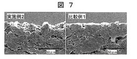
リチウムイオン伝導経路の形成を確認するために、走査型電子顕微鏡を用いて実施例2と比較例1の負極を断面観察した結果を図7に示す。
リチウムイオン伝導経路の形成を確認するために、走査型電子顕微鏡を用いて実施例2と比較例1の負極を断面観察した結果を図7に示す。
比較例1の負極は、活物質層の表面が平滑であり、活物質層の表面から内部へ通じる経路は確認できなかった。そのため、充電時における活物質層の内部の黒鉛へのリチウムイオンの伝導は、それより表面側にある黒鉛間のわずかな隙間に存在する電解液が担うため、リチウムイオンの伝導抵抗が大きくなってしまう。
したがって、低温で電解液のリチウムイオン伝導抵抗が大きくなる条件下の充電においては、活物質層の内部の黒鉛にリチウムイオンがほとんど到達しなくなり、活物質層の表面の黒鉛に充電電流が集中してしまう。そのため、リチウム金属の析出が起こってしまう。
一方で、実施例2の負極は、活物質層の表面が加工されており、活物質層の表面から内部に通じるリチウムイオン伝導経路が形成されていることが確認された。こうしたリチウムイオン伝導経路が存在することで、低温で電解液のリチウムイオン伝導抵抗が大きくなる条件下の充電においても、十分に負極内部の黒鉛にリチウムイオンが到達し、負極表面の黒鉛に充電電流が集中することがなくなる。そのため、リチウム金属の析出が抑制できる。
(評価2)
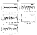
リチウムイオン伝導経路を定量的に評価するために、実施例1~4、比較例1の負極について、JIS B0601に準拠して粗さ曲線を測定し、切断レベルC=1μm、10μm、12μm、20μmにおける負荷長さ率Rmrを得た。図8に各負極の粗さ曲線の測定結果を示し、表1に負荷長さ率Rmrを示す。
リチウムイオン伝導経路を定量的に評価するために、実施例1~4、比較例1の負極について、JIS B0601に準拠して粗さ曲線を測定し、切断レベルC=1μm、10μm、12μm、20μmにおける負荷長さ率Rmrを得た。図8に各負極の粗さ曲線の測定結果を示し、表1に負荷長さ率Rmrを示す。
(評価3)
実施例1~4、比較例1の負極における低温充電時のリチウム金属析出量を評価するために、実施例1~4、比較例1の試験電池を用いて-20℃で20サイクルの充放電試験を行った。その後、電池をアルゴン雰囲気のグローブボックス内で解体し、銅箔上の負極を採取したものに塩化リチウムを外部標準として加えて、7Li-NMRにてリチウム金属析出量を定量分析した。各負極におけるリチウム金属析出量を表1に示す。
実施例1~4、比較例1の負極における低温充電時のリチウム金属析出量を評価するために、実施例1~4、比較例1の試験電池を用いて-20℃で20サイクルの充放電試験を行った。その後、電池をアルゴン雰囲気のグローブボックス内で解体し、銅箔上の負極を採取したものに塩化リチウムを外部標準として加えて、7Li-NMRにてリチウム金属析出量を定量分析した。各負極におけるリチウム金属析出量を表1に示す。
表1に示すように、実施例1~4の負極は、比較例1に比べてリチウム金属析出量が少ないことが分かった。また、切断レベル10μm、12μmにおける負荷長さ率Rmrとリチウム金属析出量には良い相関が見られ、負荷長さ率Rmrが小さいものほどリチウム金属析出量が少なかった。
切断レベル10μmでは、負荷長さ率Rmrを98.5%以下とすることでリチウム金属の析出を抑制することができ、更に95.6%以下とすることで、ほとんどリチウム金属の析出が見られなくなることが分かった。また、切断レベル12μmでは、負荷長さ率Rmrを99.3%以下とすることでリチウム金属の析出を抑制することができ、更に97.5%以下とすることで、ほとんどリチウム金属の析出が見られなくなることが分かった。一方で、切断レベル1μm、20μmでは、負荷長さ率Rmrの値とリチウム金属析出量に明確な相関が見られなかった。
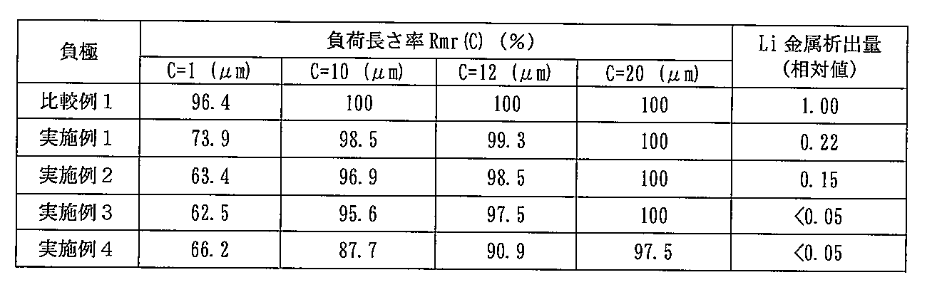
以上より、負極の活物質層の表面から内部に通じるリチウムイオン伝導経路を適切に設けることで、低温充電時に負極にリチウム金属が析出することを抑制できることが分かった。リチウムイオン伝導経路は、切断レベル10μmにおける負荷長さ率Rmrが98.5%以下、より好ましくは95.6%以下となるように設けることが良い。また、切断レベル12μmにおける負荷長さ率Rmrが99.3%以下、より好ましくは97.5%以下となるように設けることが良い。
以上、本発明の実施形態について詳述したが、本発明は、前記の実施形態に限定されるものではなく、特許請求の範囲に記載された本発明の精神を逸脱しない範囲で、種々の設計変更を行うことができるものである。例えば、前記した実施の形態は本発明を分かりやすく説明するために詳細に説明したものであり、必ずしも説明した全ての構成を備えるものに限定されるものではない。また、ある実施形態の構成の一部を他の実施形態の構成に置き換えることが可能であり、また、ある実施形態の構成に他の実施形態の構成を加えることも可能である。さらに、各実施形態の構成の一部について、他の構成の追加・削除・置換をすることが可能である。
100 負極
101 集電箔
102 活物質層
103 黒鉛
104 結着剤
105 リチウムイオン伝導経路
301 粘着テープ
302 活物質層の表面の一部の黒鉛
400 負極
401 集電箔
402 活物質層
403 ローラー
404 粘着テープ
405 ローラー
500 リチウムイオン二次電池
501 密閉ケース
511 負極
512 負極集電箔
513 負極活物質層
521 正極
522 正極集電箔
523 正極活物質層
531 セパレータ
600 リチウムイオン二次電池
601 電池缶
602 電極群
603 負極タブ
604 正極タブ
605 電池蓋
607 内蓋
608 内圧開封弁
609 ガスケット
610 PTC素子
611 負極
621 正極
631 セパレータ
Claims (11)
- 集電体と、該集電体の上に形成された活物質層とを有するリチウムイオン二次電池用負極であって、
前記活物質層は、活物質として黒鉛を有し、
前記活物質層の表面粗さ測定によって得られる粗さ曲線の平均線を前記活物質層の表面から内部方向へ10μm、平行移動させた線で切断した切断長さの和の基準長さに対する比を百分率で表した負荷長さ率(Rmr(10μm))が、50%以上、98.5%以下であることを特徴とするリチウムイオン二次電池用負極。 - 前記負荷長さ率(Rmr(10μm))が、50%以上、95.6%以下であることを特徴とする請求項1に記載のリチウムイオン二次電池用負極。
- 前記活物質層の表面粗さ測定によって得られる粗さ曲線の平均線を負極内部方向へ12μm、平行移動させた線で切断した切断長さの和の基準長さに対する比を百分率で表した負荷長さ率(Rmr(12μm))が、50%以上、99.3%以下であることを特徴とする請求項1または2に記載のリチウムイオン二次電池用負極。
- 前記負荷長さ率(Rmr(12μm))が、50%以上、97.5%以下であることを特徴とする請求項3に記載のリチウムイオン二次電池用負極。
- 前記活物質層の密度が1.2g/cm3以上であることを特徴とする請求項1から請求項4のいずれか一項に記載のリチウムイオン二次電池用負極。
- 正極との間にセパレータを介して重ね合わされて捲回することによって電極群を構成し、
前記負極の捲き始め端部側よりも捲き終わり端部側の方が前記負荷長さ率(Rmr(10μm))が小さいことを特徴とする請求項1から請求項5のいずれか一項に記載のリチウムイオン二次電池用負極。 - 正極との間にセパレータを介して重ね合わされて電極群を構成し、
前記正極に対向する正極対向部の前記負荷長さ率(Rmr(10μm))が50%以上、98.5%以下であることを特徴とする請求項1から請求項5のいずれか一項に記載のリチウムイオン二次電池用負極。 - 請求項1から請求項7のいずれか一項に記載のリチウムイオン二次電池用負極を有するリチウムイオン二次電池。
- 黒鉛を有する活物質層が集電体の上に形成されたリチウムイオン二次電池用負極の製造方法であって、
前記活物質層の表面を加工して、該活物質層の表面粗さ測定によって得られる粗さ曲線の平均線を前記活物質層の表面から内部方向へ10μm、平行移動させた線で切断した切断長さの和の基準長さに対する比を百分率で表した負荷長さ率(Rmr(10μm))が、50%以上、98.5%以下とする表面加工工程を含むことを特徴とするリチウムイオン二次電池用負極の製造方法。 - 前記表面加工工程は、
前記活物質層の表面に粘着テープを貼着する工程と、
該粘着テープを剥がして前記活物質層の表面から一部の黒鉛を剥離する工程とを含むことを特徴とする請求項9に記載のリチウムイオン二次電池用負極の製造方法。 - 前記表面加工工程は、
前記活物質層の表面に針状の突起部を押し付ける工程を含むことを特徴とする請求項9に記載のリチウムイオン二次電池用負極の製造方法。
Priority Applications (2)
| Application Number | Priority Date | Filing Date | Title |
|---|---|---|---|
| PCT/JP2012/071491 WO2014030260A1 (ja) | 2012-08-24 | 2012-08-24 | リチウムイオン二次電池用負極およびその製造方法 |
| JP2014531474A JP5968444B2 (ja) | 2012-08-24 | 2012-08-24 | リチウムイオン二次電池用負極およびその製造方法 |
Applications Claiming Priority (1)
| Application Number | Priority Date | Filing Date | Title |
|---|---|---|---|
| PCT/JP2012/071491 WO2014030260A1 (ja) | 2012-08-24 | 2012-08-24 | リチウムイオン二次電池用負極およびその製造方法 |
Publications (1)
| Publication Number | Publication Date |
|---|---|
| WO2014030260A1 true WO2014030260A1 (ja) | 2014-02-27 |
Family
ID=50149593
Family Applications (1)
| Application Number | Title | Priority Date | Filing Date |
|---|---|---|---|
| PCT/JP2012/071491 Ceased WO2014030260A1 (ja) | 2012-08-24 | 2012-08-24 | リチウムイオン二次電池用負極およびその製造方法 |
Country Status (2)
| Country | Link |
|---|---|
| JP (1) | JP5968444B2 (ja) |
| WO (1) | WO2014030260A1 (ja) |
Citations (8)
| Publication number | Priority date | Publication date | Assignee | Title |
|---|---|---|---|---|
| JPH07122262A (ja) * | 1993-10-27 | 1995-05-12 | Toray Ind Inc | 電極およびその製造方法、およびそれを用いた二次電池 |
| JPH09283139A (ja) * | 1996-04-09 | 1997-10-31 | Matsushita Electric Ind Co Ltd | リチウム二次電池およびその製造法 |
| JPH1145738A (ja) * | 1997-05-30 | 1999-02-16 | Mitsubishi Chem Corp | リチウム二次電池及びその製造方法 |
| JP2000323174A (ja) * | 1999-05-12 | 2000-11-24 | Japan Storage Battery Co Ltd | 非水電解質二次電池 |
| JP2005327527A (ja) * | 2004-05-13 | 2005-11-24 | Toshiba Corp | 非水電解質二次電池 |
| JP2007042386A (ja) * | 2005-08-02 | 2007-02-15 | Nissan Motor Co Ltd | 電池用電極およびその製造方法 |
| JP2010062136A (ja) * | 2008-06-23 | 2010-03-18 | Panasonic Corp | 非水電解質二次電池 |
| JP2011165388A (ja) * | 2010-02-05 | 2011-08-25 | Panasonic Corp | リチウムイオン二次電池用電極、前記電極を用いたリチウムイオン二次電池用電極群、前記電極群を用いたリチウムイオン二次電池 |
-
2012
- 2012-08-24 WO PCT/JP2012/071491 patent/WO2014030260A1/ja not_active Ceased
- 2012-08-24 JP JP2014531474A patent/JP5968444B2/ja not_active Expired - Fee Related
Patent Citations (8)
| Publication number | Priority date | Publication date | Assignee | Title |
|---|---|---|---|---|
| JPH07122262A (ja) * | 1993-10-27 | 1995-05-12 | Toray Ind Inc | 電極およびその製造方法、およびそれを用いた二次電池 |
| JPH09283139A (ja) * | 1996-04-09 | 1997-10-31 | Matsushita Electric Ind Co Ltd | リチウム二次電池およびその製造法 |
| JPH1145738A (ja) * | 1997-05-30 | 1999-02-16 | Mitsubishi Chem Corp | リチウム二次電池及びその製造方法 |
| JP2000323174A (ja) * | 1999-05-12 | 2000-11-24 | Japan Storage Battery Co Ltd | 非水電解質二次電池 |
| JP2005327527A (ja) * | 2004-05-13 | 2005-11-24 | Toshiba Corp | 非水電解質二次電池 |
| JP2007042386A (ja) * | 2005-08-02 | 2007-02-15 | Nissan Motor Co Ltd | 電池用電極およびその製造方法 |
| JP2010062136A (ja) * | 2008-06-23 | 2010-03-18 | Panasonic Corp | 非水電解質二次電池 |
| JP2011165388A (ja) * | 2010-02-05 | 2011-08-25 | Panasonic Corp | リチウムイオン二次電池用電極、前記電極を用いたリチウムイオン二次電池用電極群、前記電極群を用いたリチウムイオン二次電池 |
Also Published As
| Publication number | Publication date |
|---|---|
| JPWO2014030260A1 (ja) | 2016-07-28 |
| JP5968444B2 (ja) | 2016-08-10 |
Similar Documents
| Publication | Publication Date | Title |
|---|---|---|
| CN110137442B (zh) | 基于石墨的负电极活性材料、负电极和锂离子二次电池 | |
| CN104241613B (zh) | 蓄电元件和蓄电池模块 | |
| CN102939675B (zh) | 非水电解液二次电池 | |
| CN108140830A (zh) | 锂离子二次电池及其制造方法 | |
| JP5818078B2 (ja) | 非水電解質二次電池の製造方法 | |
| US20220173377A1 (en) | Thick electrodes for electrochemical cells | |
| CN102714298A (zh) | 用于镁二次电池的电极及包括该电极的镁二次电池 | |
| JPWO2019156031A1 (ja) | リチウムイオン二次電池用電極、その製造方法、及びリチウムイオン二次電池 | |
| WO2013038672A1 (ja) | 非水電解質二次電池 | |
| WO2015005067A1 (ja) | リチウムイオン二次電池用集電体およびリチウムイオン二次電池用正極 | |
| CN105390752B (zh) | 非水电解质二次电池及其制造方法和用于非水电解质二次电池的分离器 | |
| JP2015037008A (ja) | 非水電解質二次電池用の電極活物質層とその製造方法 | |
| US20230246161A1 (en) | Pre-lithiation, precursor electrodes and methods of making and using the same | |
| JP6237777B2 (ja) | 負極活物質、それを用いた負極、及びリチウムイオン二次電池 | |
| US12438147B2 (en) | Lithium-containing particle coatings for positive electroactive materials | |
| JP5692605B2 (ja) | 非水電解液二次電池 | |
| CN115148998A (zh) | 锂离子二次电池用电极及锂离子二次电池 | |
| CN105359310B (zh) | 负极活性物质、使用其的负极和锂离子二次电池 | |
| JP6128228B2 (ja) | 負極活物質、それを用いた負極、及びリチウムイオン二次電池 | |
| US20240030552A1 (en) | Protective layers separating electroactive materials and binder materials in electrode and methods of forming the same | |
| JP5104333B2 (ja) | リチウムイオン二次電池の耐久性改良方法 | |
| JP2018133297A (ja) | 非水電解質二次電池 | |
| JP5968444B2 (ja) | リチウムイオン二次電池用負極およびその製造方法 | |
| JP5195006B2 (ja) | リチウム二次電池用負極及びリチウム二次電池 | |
| JP2018133298A (ja) | 非水電解質二次電池 |
Legal Events
| Date | Code | Title | Description |
|---|---|---|---|
| 121 | Ep: the epo has been informed by wipo that ep was designated in this application |
Ref document number: 12883308 Country of ref document: EP Kind code of ref document: A1 |
|
| ENP | Entry into the national phase |
Ref document number: 2014531474 Country of ref document: JP Kind code of ref document: A |
|
| NENP | Non-entry into the national phase |
Ref country code: DE |
|
| 122 | Ep: pct application non-entry in european phase |
Ref document number: 12883308 Country of ref document: EP Kind code of ref document: A1 |