WO2014027602A1 - 開封検知複合キャップ - Google Patents
開封検知複合キャップ Download PDFInfo
- Publication number
- WO2014027602A1 WO2014027602A1 PCT/JP2013/071490 JP2013071490W WO2014027602A1 WO 2014027602 A1 WO2014027602 A1 WO 2014027602A1 JP 2013071490 W JP2013071490 W JP 2013071490W WO 2014027602 A1 WO2014027602 A1 WO 2014027602A1
- Authority
- WO
- WIPO (PCT)
- Prior art keywords
- overcap
- cap
- inner cap
- opening
- film
- Prior art date
- Legal status (The legal status is an assumption and is not a legal conclusion. Google has not performed a legal analysis and makes no representation as to the accuracy of the status listed.)
- Ceased
Links
Images





Classifications
-
- B—PERFORMING OPERATIONS; TRANSPORTING
- B65—CONVEYING; PACKING; STORING; HANDLING THIN OR FILAMENTARY MATERIAL
- B65D—CONTAINERS FOR STORAGE OR TRANSPORT OF ARTICLES OR MATERIALS, e.g. BAGS, BARRELS, BOTTLES, BOXES, CANS, CARTONS, CRATES, DRUMS, JARS, TANKS, HOPPERS, FORWARDING CONTAINERS; ACCESSORIES, CLOSURES, OR FITTINGS THEREFOR; PACKAGING ELEMENTS; PACKAGES
- B65D51/00—Closures not otherwise provided for
- B65D51/18—Arrangements of closures with protective outer cap-like covers or of two or more co-operating closures
- B65D51/185—Arrangements of closures with protective outer cap-like covers or of two or more co-operating closures the outer closure being a foil membrane
-
- B—PERFORMING OPERATIONS; TRANSPORTING
- B65—CONVEYING; PACKING; STORING; HANDLING THIN OR FILAMENTARY MATERIAL
- B65D—CONTAINERS FOR STORAGE OR TRANSPORT OF ARTICLES OR MATERIALS, e.g. BAGS, BARRELS, BOTTLES, BOXES, CANS, CARTONS, CRATES, DRUMS, JARS, TANKS, HOPPERS, FORWARDING CONTAINERS; ACCESSORIES, CLOSURES, OR FITTINGS THEREFOR; PACKAGING ELEMENTS; PACKAGES
- B65D51/00—Closures not otherwise provided for
- B65D51/18—Arrangements of closures with protective outer cap-like covers or of two or more co-operating closures
-
- B—PERFORMING OPERATIONS; TRANSPORTING
- B65—CONVEYING; PACKING; STORING; HANDLING THIN OR FILAMENTARY MATERIAL
- B65D—CONTAINERS FOR STORAGE OR TRANSPORT OF ARTICLES OR MATERIALS, e.g. BAGS, BARRELS, BOTTLES, BOXES, CANS, CARTONS, CRATES, DRUMS, JARS, TANKS, HOPPERS, FORWARDING CONTAINERS; ACCESSORIES, CLOSURES, OR FITTINGS THEREFOR; PACKAGING ELEMENTS; PACKAGES
- B65D55/00—Accessories for container closures not otherwise provided for
- B65D55/02—Locking devices; Means for discouraging or indicating unauthorised opening or removal of closure
- B65D55/026—Locking devices; Means for discouraging or indicating unauthorised opening or removal of closure initial opening or unauthorised access being indicated by a visual change using indicators other than tearable means, e.g. change of colour, pattern or opacity
-
- B—PERFORMING OPERATIONS; TRANSPORTING
- B65—CONVEYING; PACKING; STORING; HANDLING THIN OR FILAMENTARY MATERIAL
- B65D—CONTAINERS FOR STORAGE OR TRANSPORT OF ARTICLES OR MATERIALS, e.g. BAGS, BARRELS, BOTTLES, BOXES, CANS, CARTONS, CRATES, DRUMS, JARS, TANKS, HOPPERS, FORWARDING CONTAINERS; ACCESSORIES, CLOSURES, OR FITTINGS THEREFOR; PACKAGING ELEMENTS; PACKAGES
- B65D2251/00—Details relating to container closures
- B65D2251/0003—Two or more closures
- B65D2251/0006—Upper closure
- B65D2251/0015—Upper closure of the 41-type
-
- B—PERFORMING OPERATIONS; TRANSPORTING
- B65—CONVEYING; PACKING; STORING; HANDLING THIN OR FILAMENTARY MATERIAL
- B65D—CONTAINERS FOR STORAGE OR TRANSPORT OF ARTICLES OR MATERIALS, e.g. BAGS, BARRELS, BOTTLES, BOXES, CANS, CARTONS, CRATES, DRUMS, JARS, TANKS, HOPPERS, FORWARDING CONTAINERS; ACCESSORIES, CLOSURES, OR FITTINGS THEREFOR; PACKAGING ELEMENTS; PACKAGES
- B65D2251/00—Details relating to container closures
- B65D2251/0003—Two or more closures
- B65D2251/0068—Lower closure
- B65D2251/0078—Lower closure of the 41-type
-
- B—PERFORMING OPERATIONS; TRANSPORTING
- B65—CONVEYING; PACKING; STORING; HANDLING THIN OR FILAMENTARY MATERIAL
- B65D—CONTAINERS FOR STORAGE OR TRANSPORT OF ARTICLES OR MATERIALS, e.g. BAGS, BARRELS, BOTTLES, BOXES, CANS, CARTONS, CRATES, DRUMS, JARS, TANKS, HOPPERS, FORWARDING CONTAINERS; ACCESSORIES, CLOSURES, OR FITTINGS THEREFOR; PACKAGING ELEMENTS; PACKAGES
- B65D2401/00—Tamper-indicating means
- B65D2401/15—Tearable part of the closure
- B65D2401/25—Non-metallic tear-off strips
Definitions
- the present invention relates to a composite cap used for sealing a mouth portion of a packaging container filled with contents, and more specifically, an inner cap provided in a container mouth portion and a cover for the inner cap. It is related with the unseal
- the mouth of the packaging container filled with contents from the viewpoint of preventing tampering and preventing unauthorized use due to replacement of the contents and ensuring the quality of the contents.
- the function of clearly indicating the opening of the cap that seals is required.
- the cap has a double structure for the purpose of improving child resistance and cap opening, attaching an IC tag, or mixing predetermined additives into the contents simultaneously with opening.
- Patent Documents 1 to 3 For example, see Patent Documents 1 to 3).
- the mouth of the container is sealed by the inner cap, and an overcap is provided so as to cover the inner cap. That is, when the inner cap is provided so as to rotate in the opening direction in conjunction with the rotation of the overcap, and when an operation such as pushing the overcap is required prior to the rotation of the overcap, If child resistance can be realized and the overcap can be rotated immediately, the inner cap with a smaller diameter can be rotated in the opening direction by rotating the overcap with a larger diameter. Can be improved.
- the overcap by providing an IC tag on the overcap, contact between the IC tag and contents is prevented, and information stored in the IC chip provided in the IC tag is read or information is input to the IC chip. Can be reliably performed without malfunction. Furthermore, if there is a space in the upper surface of the inner cap to store additives, etc., and the structure is such that the upper surface of the inner cap breaks due to the rotation of the overcap, the additive is mixed with the container contents at the same time as opening. can do.
- a means of providing a stopper band at the lower end of the overcap is the most common. That is, a stopper band that is tightly engaged with the inner cap or the outer surface of the container mouth is provided at the lower end of the overcap, and operations such as turning or pushing of the overcap cannot be performed unless the band is peeled off. This is the structure.
- the stopper band has been peeled off, a general consumer can recognize the fact that the mouth of the container has been opened, but that the stopper band has been peeled off, Often not noticed by general consumers. This is because even when the stopper band has been peeled off, the upper form of the stopper band has exactly the same form as a normal overcap.
- an object of the present invention is to enhance the opening and closing function of a composite cap having a double structure in which an overcap is provided so as to cover the inner cap and the inner cap for sealing the container mouth.
- an inner cap provided at a container mouth portion, an overcap that covers the inner cap, and an opening clarification film disposed at a position between the inner cap and the overcap are provided.
- the opening detection composite cap When removing the inner cap from the container mouth, the overcap is attached to the inner cap so as to include at least a process of moving relative to the inner cap, The inner cap is provided with a cutter for breaking the opening manifestation film in relative movement with the overcap, An opening detection composite cap is provided in which the overcap is provided with a window for visually confirming the breakage of the film for revealing opening.
- the unsealing detection composite cap of the present invention has an excellent unsealing function.
- the composite cap of the present invention (1) using a hologram film as the film for revealing opening; Is preferred.
- a hologram film is used, the hologram image is not displayed by breaking the portion of the film where the hologram pattern is formed, and from this, the fact that the hologram film is broken, that is, opened, is surely visually confirmed. Because it can be done.
- an image film on which a normal printed image is formed is used as a film for revealing an opening, a part of the image may be damaged by tearing or curling of the film, rather than being invisible due to the film breaking. As a result, the visibility is slightly inferior to the case where no image is displayed.
- the inner cap is provided at the container mouth by screw engagement, and includes a top plate and a screw thread that descends from the top plate periphery and engages the outer surface of the mouth of the container on the inner surface. And the cutter is formed on the top surface of the top plate,
- the overcap has a top wall panel and a skirt descending from the periphery of the top wall panel, the window is provided in the top wall panel, and the opening manifestation film is provided on the lower surface of the top wall panel. Installed, Between the inner surface of the skirt of the overcap and the outer surface of the cylindrical wall of the inner cap, there is provided engaging means for transmitting the rotation of the overcap that is put on the inner cap to the inner cap.
- a gap is maintained between the top surface of the top plate of the inner cap and the bottom surface of the top wall panel of the overcap that covers the inner cap; Is preferred. That is, in such an embodiment, the seal of the container mouth portion by the inner cap can be released in conjunction with the normal simple operation of rotating the overcap, and during this time, the opening indication film is automatically broken, This is because the fact of opening is clearly indicated.
- various means can be employ
- a stopper band is provided at the lower end of the skirt of the overcap, the stopper band is located below the lower end of the cylindrical side wall of the inner cap and the overcap is raised and / or lowered.
- Engaged with the outer surface of the mouth of the container so as to be regulated By adopting the means, it is possible to effectively prevent the tear-opening film from being broken by the movement of the overcap before the container is opened.
- the overcap film can be immediately broken and the container can be opened and the container can be opened.
- the inner cap is removed from the container mouth with the overcap covered, but it can be easily separated from the overcap, and only the inner cap can be easily used for resealing. is there.
- the stopper band is provided so as to be separable from the lower end of the skirt of the overcap,
- the opening and tearing film is broken and opened. Therefore, not only the film for revealing the opening but also the presence of the stopper band, it can be confirmed that the container is in an unopened state, further improving the function for revealing the opening, preventing tampering and quality of the contents of the container. This is extremely advantageous in terms of guarantee.
- the stopper band when the stopper band is provided so as to be detachable from the overcap, (6)
- the outer surface of the cylindrical wall of the inner cap and the inner surface of the skirt of the overcap are respectively formed with threads that engage with each other, and these threads function as the engaging means,
- the screw engagement between the outer surface of the cylindrical wall and the inner surface of the skirt is in a reverse screw relationship with respect to the screw engagement between the inner surface of the cylindrical wall of the inner cap and the outer surface of the mouth of the container, and after the stopper band is detached.
- the film for revealing opening is broken by the cutter due to the descent accompanying the rotation of the overcap, and the inner cap rotates in the opening direction by continuing the rotation of the overcap.
- the means In this aspect, after the stopper band is cut off, the opening cap film can be broken and the container can be opened only by the operation of rotating the overcap immediately. In addition to the advantages of the above aspect (5), the operation Is very easy.
- the stopper band when the stopper band is provided so as to be detachable from the overcap, (7) A protrusion projecting downward is formed on the lower surface of the top wall panel of the overcap, and a recess into which the protrusion can be fitted is formed on the upper surface of the top plate of the inner cap.
- the projecting portion and the recessed portion are the engaging means, and when the overcap is pushed in by separating the stopper band, the opening manifesting film is broken by the cutter, and at the same time, the projecting portion Entering into the recess and engaging, allowing the overcap to rotate in the opening direction of the inner cap, This aspect can also be adopted.
- an operation of once pushing the overcap is required. For this reason, it is excellent in the so-called child resistance property that it is difficult for an infant or the like to open, and in particular, the contents are preferably used as a cap of a container of a medicine or the like.
- an IC tag can be attached to the lower surface of the film for revealing opening.
- the opening manifestation film but also the IC tag is ruptured, and it is possible not only to confirm the presence of opening by observing the opening manifestation film, but also to read (or cannot read) information from the IC chip of the IC tag. The presence or absence of opening can also be confirmed.
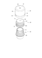
- FIG. 6 is an exploded perspective view of the composite cap of FIG. 5.
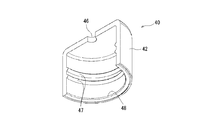
- FIG. 6 is a cut perspective view of an overcap in the composite cap of FIG. 5.
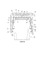
- FIG. 6 is a side cross-sectional view of the composite cap of FIG.
- FIG. 10 is a cut perspective view of an overcap in the composite cap of FIG. 9.
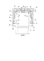
- FIG. 10 is a side sectional view of the composite cap of FIG. The figure for demonstrating the method of applying the composite cap of this invention to the existing packaging container.
- a film having a broken state for example, a film having an image portion is used.
- a typical example of such a tamper-evident film is also called a hologram film, which is well known per se. That is, such a hologram film is generally indicated by 200 in FIG. 1, and has a structure in which a hologram layer 203 having an image region X is formed on a film or sheet-like substrate 201.
- the base material 201 is not particularly limited as long as the hologram film can be broken by a resin projection that functions as a cutter, and may be a metal foil such as an aluminum foil or a resin sheet or film, or a resin.
- a metal sheet such as Al or an oxide layer thereof may be formed on the surface of the manufactured sheet or film.
- a metal foil or a vapor deposition layer of metal or metal oxide is provided on the surface.
- a resin sheet or film is preferred.
- the image area X of the hologram layer 203 is formed by arranging minute recesses 205 at small intervals, and the size and interval of the recesses 205 are close to the visible light wavelength (about 400 nm to 700 nm). It is. That is, when a large number of such concave portions 205 are regularly arranged, light is diffracted. For example, light reflected by the surface of the base material 201 is interfered with light due to an optical path difference between the concave portions 205. As a result, a hologram image appears in the image region X.
- the hologram layer 203 only needs to be formed of a light-transmitting resin that can form the fine recesses 205 with a predetermined arrangement pattern by means such as casting, embossing, laser processing, and photoresist.
- a light-transmitting resin that can form the fine recesses 205 with a predetermined arrangement pattern by means such as casting, embossing, laser processing, and photoresist.
- it may be formed of various thermoplastic resins, heat or light curable resins, photosensitive resins, and the like.
- a transparent protective resin layer can be appropriately provided on the above-described hologram layer 203 in order to prevent entry of foreign matter into the recess 205.
- a transparent protective resin layer is formed by, for example, a thermosetting resin paint, a thermoplastic resin paint, an ultraviolet curable paint or the like used as a finishing varnish for polishing.
- the hologram film 200 having the above structure is such that when the image region X is destroyed, the hologram image disappears, and in the present invention, the fact that the container is opened is used. It shows.
- the film for revealing unsealing is not limited to the hologram film 200 described above, as long as it is broken by the unsealing operation and the break can be visually recognized from the outside, a paper sheet, a metal foil, or A printing film in which an ink image is formed by ordinary printing on a substrate such as a resin film can also be used.
- the formed ink image is formed at a position visually recognized from the outside.
- the hologram film 200 described above may be used as a film for revealing unfolded from the viewpoint that it is excellent in unwrapping clarity in order to show the fact of breakage due to the disappearance of the image. Is optimal.
- an IC tag known per se can be attached to the lower surface of the above-described opening indication film.
- An opening detection composite cap (hereinafter simply referred to as a composite cap) of the present invention includes an inner cap that is attached to a container mouth and seals the container mouth, and an overcap that covers the inner cap.
- the above-described opening film such as a hologram film is provided between the overcap and the overcap, and the overcap is used to release the seal of the container mouth by the inner cap (that is, open the inner cap).
- the stopper opening film is broken by a protrusion (cutter) provided on the inner cap using the relative movement between the caps, and the fact of the break is visually recognized from the window provided on the overcap. And thus general consumers can break through tear film It is possible to recognize the fact of the seal.
- the composite cap of the present invention includes a process in which the overcap and the inner cap relatively move when opened, and specifically, a structure in which the overcap is used to move the inner cap in the opening direction.
- a structure is not particularly limited, and may have an appropriate form, but generally, from the viewpoint that the opening of the inner cap can be easily controlled as a rotation and can be performed by a simple operation.
- the inner cap has a structure that is attached to the container mouth portion by screw engagement.
- the composite cap of the present invention having such a screw engagement type is roughly classified into three types, that is, a polyhedral type, a reverse screw type, and a fitting type, depending on the type of engagement between the overcap and the inner cap.
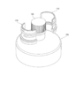
- this type of composite cap includes an inner cap (denoted as a whole by 30) provided in a mouth portion (denoted as a whole by 20) of a container such as a bottle by screw engagement, An overcap (indicated by 40 as a whole) is provided so as to cover the inner cap 30.
- a screw thread 21 is formed above, a jaw portion 23 is formed below it, and a support ring 25, which is a projecting portion having the largest diameter, is formed below it. .
- the inner cap 30 has a top plate 31 and a cylindrical wall 32 that descends from the periphery of the top plate. On the inner surface of the cylindrical wall 32, as shown in FIG. A thread 33 is provided. That is, the inner cap 30 is held by the container mouth portion 20 by screw engagement between the thread 33 and the outer thread 21 of the container mouth portion 20.
- a holding band 34 for holding the inner cap 30 firmly is provided integrally with the cylindrical wall 32 at the lower end of the cylindrical wall 32. That is, as shown in FIG. 2, the holding band 34 extends to the lower side of the jaw portion 23 on the outer surface of the container mouth portion 20, and the lower surface of the jaw portion 23 is formed on the inner surface thereof.
- An engagement projection (or flap piece) 34a is formed, and the inner cap 30 is firmly held on the outer surface of the container mouth portion 20 by the engagement between the engagement projection 34a and the jaw portion 23. It has come to be.
- the outer surface of the cylindrical wall 32 has a polyhedral shape, and this surface is engaged with an overcap 40 described later. .
- an inner ring 35 is provided at a peripheral portion of the lower surface of the top plate 31 of the inner cap 30 with a space from the cylindrical wall 32 (see FIG. 2). That is, the upper end of the container mouth portion 20 enters the space between the cylindrical wall 32 and the inner ring 35, and the outer surface of the inner ring 35 comes into close contact with the inner surface of the upper end portion of the container mouth portion 20, thereby The internal sealing performance is secured.
- a projection 36 serving as a cutter is formed on the top surface of the top plate 31 at the center thereof, and the opening manifestation film 10 attached to the overcap 40 by the cutter 36. Is designed to break.
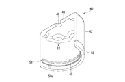
- the overcap 40 fixed on the inner cap 30 described above has a top wall panel 41 and a skirt 42 that descends from the periphery of the top wall panel 41.
- a polyhedron portion 43 corresponding to the polyhedron on the outer surface of the cylindrical wall 32 of the inner cap 30 described above is formed on the upper surface of the inner surface of the skirt 42. That is, the polyhedron 43 is engaged with the outer polyhedron of the cylindrical wall 32 of the inner cap 30, whereby the inner cap 30 can be rotated by the rotation of the overcap 40.
- a knurl 42 a for facilitating the rotation of the overcap 40 is formed on the outer surface of the skirt 42.
- a band portion 50 serving as a stopper is formed at the lower end of the skirt 42, and an engagement protrusion 55 is formed on the inner surface thereof. 55 is engaged with the lower surface of the support ring 25 on the outer surface of the container mouth portion 20, so that the rise of the overcap 40 is restricted.
- the engagement protrusion 55 is strongly engaged with the lower surface of the support ring 25, and the engagement force is stronger than the engagement force between the holding band 34 (engagement protrusion 34 a) of the inner cap 30 and the jaw part 23.
- a step 45 is formed on the inner surface of the boundary between the lower end of the skirt 42 and the band portion 50. That is, the step 45 is engaged with the upper surface of the support ring 25, so that the lowering of the overcap 40 is restricted.
- the top wall panel 41 is provided with a window 46 for confirming the presence or absence of breakage of the unsealing film. Further, as shown in FIG. 2, the above-described opening manifestation film 10 is attached to the lower surface. In FIG. 4, the opening manifest film 10 is omitted.
- the window 46 is a hole that penetrates the top wall panel 41. Further, the hole may be covered with a transparent film or the like.
- the window 46 is preferably provided at a position corresponding to the cutter 36 and provided at the center of the top wall panel 41.
- the shape of the window 46 is not particularly limited as long as the internal opening-opening film 10 can be visually recognized.
- the unsealing film 10 may be attached to the lower surface of the top wall panel 41 by adjusting its size, or may be attached by an adhesive or heat seal. It may be. In this case, since the part located on the window 46 becomes a part to be broken by the cutter 36, it is attached so that the image area (area indicated by X in FIG. 1) of the unsealing film 10 is located at this position. .
- the overcap 40 when the overcap 40 is provided by plugging over the inner cap 30 attached to the container mouth portion 20, the lower end of the skirt 42 and the engagement protrusion 44 a of the band portion 44. Is located below the support ring 25 on the outer surface of the container mouth portion 20, but the step 45 at the boundary between the band portion 50 and the skirt 42 engages with the upper surface of the support ring 25, so A certain distance L is ensured between the lower surface of the wall panel 41 and the upper surface of the top plate 31 of the inner cap 30, and as a result, the opening-clarifying film 10 is held without being broken.
- the overcap 40 when the overcap 40 is rotated in the opening direction, the polyhedral body 43 on the inner surface of the skirt 42 and the outer surface (polyhedral surface) of the cylindrical wall 32 of the inner cap 30. And the inner cap 30 also rotates in the opening direction. Therefore, the inner cap 30 is lifted along the outer surface of the container mouth portion 20 by releasing the screw engagement, and the engaging protrusion 34a gets over the jaw portion 23 formed on the outer surface of the container mouth portion 20. Become. On the other hand, in the overcap 40, since the engagement protrusion 44a of the band part 44 is strongly engaged with the support ring 25 of the container mouth part 20, the rise is restricted.
- the cutter 36 provided on the top plate 31 of the inner cap 30 removes the opening manifestation film 10 attached to the top wall panel of the overcap 40.
- the overcap 40 is pushed upward by the inner cap 30, so that the engagement protrusion 55 of the band portion 50 gets over the support ring 25 of the container mouth portion 20 and rises together with the inner cap 30. However, it is removed from the container mouth 20 while being covered with the inner cap 30.
- the inner cap 30 and the overcap 40 thus removed from the container mouth 20 can be attached to the container mouth 20 and used for resealing while the overcap 40 is put on the inner cap 30. It is also possible to remove the overcap 40 and use only the inner cap 30 for resealing.
- the opening clarification film 10 provided in the overcap 40 is broken. Accordingly, even when the inner cap 30 is covered with the overcap 40 and is resealed by being attached to the container mouth portion 20, the general consumer accurately observes the fact of opening by observing from the window 46. Can be recognized. For this reason, such a composite cap is excellent in a tamper-proof function, and unauthorized use such as content replacement can be effectively prevented by recognizing the opening fact.
- the opening cap film 10 can be broken and the inner cap 30 can be removed (opened) from the container opening 20 only by a simple operation of rotating the overcap in the opening direction.
- this type of composite cap also has an inner cap 30 attached to the mouth portion 20 of the container by screw engagement, similar to the polyhedral composite cap described above.
- An overcap 40 is put on the top.
- a screw 21, a jaw part 23, and a support ring 25 are formed on the outer surface of the container mouth part 20 in order from the top.
- the inner cap 30 has a top plate 31 and a cylindrical wall 32 descending from the periphery of the top plate. On the inner surface of the cylindrical wall 32, as shown in FIG. A thread 33 that engages with the outer thread 21 is provided, and the inner cap 30 is held by the container opening 20 by this thread engagement.
- an inner ring 35 is provided at a peripheral portion of the lower surface of the top plate 31 of the inner cap 30 with a space from the cylindrical wall 32 (see FIG. 5). That is, the upper end of the container mouth portion 20 enters the space between the cylindrical wall 32 and the inner ring 35 as in the slide type packaging container described above, and the outer surface of the inner ring 35 is the upper end portion of the container mouth portion 20. Adhering to the inner surface of the plate ensures sealing performance.
- a cutter 36 is formed at the center of the top surface of the top plate 31, and the opening manifestation film 10 attached to the overcap 40 is broken by the cutter 36. It is like that.
- the overcap 40 has a top wall panel 41 and a skirt 42 that descends from the periphery of the top wall panel 41.
- the inner surface of the skirt 42 is provided with a thread 47 that is threadedly engaged with the thread 37 on the outer surface of the cylindrical wall 32 of the inner cap 30.
- the screw engagement of the outer surface of the portion 20 (the screw engagement between the screw 21 and the screw 33) has a reverse screw relationship. That is, the rotation direction in which the screw engagement between the overcap 40 and the inner cap 30 is released is the rotation direction in which the screw engagement between the inner cap 30 and the container mouth portion 20 is tightened. The rotation direction in which the screw engagement is tightened is the rotation direction in which the screw engagement between the inner cap 30 and the container mouth portion 20 is released.
- the lower end of the inner surface of the skirt 42 is a stepped portion 48 that protrudes slightly into the inner bag, and this stepped portion 48 is engaged with the lower end of the skirt spreading portion 32 a of the cylindrical wall 32 of the inner cap 30. This effectively prevents the overcap 40 from slipping off.
- a stopper band 50 is connected to the lower end of the skirt 42 via a tearable bridging portion 51, and a knob 53 is provided on the outer surface of the band 50 when the band 50 is peeled off. That is, the stopper band 50 is easily peeled off from the skirt 42 by pulling the knob 53 in the circumferential direction to tear the bridge portion 51.
- FIG. 7 the overcap 40 with the stopper band 50 peeled off is shown.
- a concave surface 50a that is slightly recessed is formed on the inner surface of the stopper band 50, and an engaging projection 55 is formed on the lower portion thereof.
- the support ring 25 enters the concave surface 50 a, so that the engagement between the step 48 at the lower end of the inner surface of the skirt 42 and the flared portion 32 a of the cylindrical wall 32 described above is achieved.
- the rising of the overcap 40 is restricted, and the engagement protrusion 55 is engaged with the lower surface of the support ring 25 on the outer surface of the container mouth portion 20, whereby the lowering of the overcap 40 is restricted.
- the top wall panel 41 has a tear-opening film ruptured so as to correspond to the cutter 36 provided on the top surface of the top plate 31 of the inner cap 30 at the center thereof, just like the polyhedral composite cap.
- the window part 46 for confirmation is provided, and the film 10 for opening opening is attached (refer FIG. 5).
- the opening explicit film 10 and the engagement piece 42 a described above are omitted.
- this unsealing film 10 may be attached to the lower surface of the top wall panel 41 by mechanical means such as fitting according to the size thereof, or may be an adhesive or heat seal. It may be attached by, for example.
- the image area (area indicated by X in FIG. 1) of the opening manifestation film 10 is attached so as to be positioned on the window 46.
- the stopper band 50 (the recessed portion 50a and the engaging protrusion 55) and the container described above are provided.
- Engagement with the mouth portion 20 (support ring 25) ensures a certain distance L between the lower surface of the top wall panel 41 of the overcap 40 and the upper surface of the top plate 31 of the inner cap 30, and the film 10 for revealing opening.
- the overcap 40 is held so as not to be broken.
- the handle 53 is peeled off, and the stopper band 50 is separated from the overcap 40 (skirt 42), whereby the overcap 40 can be raised.
- the overcap 40 is rotated in the direction in which the inner cap 30 is released from the container mouth portion 20 (opening direction, indicated by an arrow in the figure), Due to the screw engagement between the screw 47 and the screw 37 of the inner cap 30 (which is in a reverse screw relationship with respect to the screw engagement between the cap 30 and the container opening 20), the overcap 40 is in contact with the inner cap 30.
- the inner cap 30 rotates in the opening direction, the screw engagement with the container opening 20 is released, and the inner cap 30 moves upward with respect to the container opening 20. Accordingly, when the rotation of the overcap 40 in the direction of opening is continued, the cutter 36 provided on the top plate 31 of the inner cap 30 removes the opening manifestation film 10 attached to the top wall panel of the overcap 40. As it breaks through and continues to rotate, the overcap 40 rises with the inner cap 30 and is removed from the container opening 20 while being covered with the inner cap 30.
- the inner cap 30 and the overcap 40 that have been removed from the container mouth 20 in this way are attached to the container mouth 20 and used for resealing by the stoppering with the overcap 40 still covering the inner cap 30. It is also possible to remove the overcap 40 and use only the inner cap 30 for resealing.
- the opening can be detected both by breaking the film for revealing opening 10 and detaching the stopper band 50. Excellent quality assurance function.
- ⁇ Mating type composite cap> Referring to FIGS. 9 to 12, even in the fitting type composite cap, an inner cap 30 that is attached to the mouth portion 20 of the container by screw engagement, and an overcap 40 that is put on the inner cap 30. It has.
- the outer surface of the container mouth portion 20 is the same as the outer surface of the bottle described for the above-described composite cap of the slide type and the reverse screw type, and the thread 21, the jaw portion 23, and the support ring 25 are formed in order from the top. .
- the inner cap 30 has a top plate 31 and a cylindrical wall 32 descending from the periphery of the top plate. On the inner surface of the cylindrical wall 32, as shown in FIG. A thread 33 that engages with the outer thread 21 is provided, and the inner cap 30 is held by the container opening 20 by this thread engagement. Further, a knurling is formed on the outer surface of the cylindrical wall 32 so that it can be easily rotated by hand when the inner cap 30 is re-sealed. Moreover, the lower part of the cylindrical wall 32 is a skirt spreading part 32a.
- An inner ring 35 is formed on the peripheral edge portion of the lower surface of the top plate 31 of the inner cap 30 at a distance from the cylindrical wall 32 (see FIG. 9), and the upper end of the container mouth portion 20 is the cylindrical wall. 32 and the inner ring 35 enters the space, and the outer surface of the inner ring 35 is in close contact with the inner surface of the upper end portion of the container mouth portion 20 to ensure the sealing performance.
- a cutter 36 is formed on the top surface of the top plate 31 at the center thereof, and the opening manifestation film 10 attached to the overcap 40 is broken by this cutter.
- a fitting notch 60 is formed on the peripheral edge of the top surface of the top plate 31 at an appropriate interval.
- the inner cap 30 can be rotated by engaging the overcap 40 with the notch 60 and rotating the overcap 40.
- the overcap 40 has a top wall panel 41 and a skirt 42 that descends from the periphery of the top wall panel 41, and the lower end of the inner surface of the skirt 42 is a stepped portion 48 that slightly projects into the inner bag. ing. That is, the stepped portion 48 is engaged with the lower end of the skirt widening portion 32a of the cylindrical wall 32 of the inner cap 30, thereby effectively preventing the overcap 40 from slipping off.
- a stopper band 50 is connected to the lower end of the skirt 42 via a tearable bridging portion 51 as in the case of the reverse screw type composite cap described above, and this is pulled on the outer surface of the band 50.
- a knob 53 for peeling off is provided. That is, the stopper band 50 is easily peeled off from the skirt 42 by pulling the knob 53 in the circumferential direction to tear the bridge portion 51.
- a concave surface 50 a is formed on the inner surface of the stopper band 50.
- the support ring 25 enters the concave surface 50a, and further lowering of the overcap 40 is restricted.
- the top wall panel 41 has the same structure as that of the polyhedral composite cap so that the center portion of the top wall panel 41 corresponds to the cutter 36 provided on the top surface of the top plate 31 of the inner cap 30,
- rupture is provided, and the film 10 for opening clarification is attached (refer FIG. 9).
- the opening manifestation film 10 is omitted.
- the opening manifestation film 10 can also be attached to the lower surface of the top wall panel 41 by mechanical means such as fitting according to its size, or can be attached by an adhesive or heat seal. Further, the unsealing clarification film 10 is also attached so that the image area (area indicated by X in FIG. 1) is located on the window portion 46.
- a fitting convex portion 62 is formed on the lower surface of the top wall panel 41 so as to correspond to the fitting notch 60 of the inner cap 30 described above (see FIG. 11). That is, in such a composite cap, these caps 30 and 40 are attached to the container mouth portion 20 by the stopper of the inner cap 30 covered with the overcap 40. 62 is set so as to be positioned on the notch 60 for fitting. Further, due to the engagement of the stopper band 50 (recess 50a) and the container mouth 20 (support ring 25), the space between the lower surface of the top wall panel 41 of the overcap 40 and the upper surface of the top plate 31 of the inner cap 30 is obtained. A certain interval L is ensured so that the opening-opening film 10 is not broken.
- the handle 53 is peeled off and the stopper band 50 is attached to the overcap 40 (skirt 42). ) So that the overcap 40 can be lowered.
- the fitting convex portion 62 is fitted into the fitting notch 60, and at the same time, the cutter 36 provided on the top plate 31 of the inner cap 30 is moved to the top wall of the overcap 40. It breaks through the opening manifestation film 10 attached to the panel and enters the window 46.
- the inner cap 30 and the overcap 40 thus removed from the container mouth 20 can be attached to the container mouth 20 and used for resealing while the overcap 40 is put on the inner cap 30. It is also possible to remove the overcap 40 and use only the inner cap 30 for resealing.
- the positioning vertical ribs are provided on the outer surface of the skirt 42 of the overcap 40. It is preferable to provide an appropriate number. That is, in this composite cap, first, the overcap 40 is put on the inner cap 30. At this time, the positioning rib is set so that the fitting convex portion 62 is positioned between the fitting concave portions 60. Thereby, it is possible to reliably prevent breakage of the unsealing clarification film 10 when the overcap 40 (the fitting convex portion 62) descends deeply.
- the inner cap 30 covered with the overcap 40 as described above is plugged into the container mouth portion 20, and then the overcap 40 is rotated in the closing direction so that the position of the positioning rib described above is reached.
- the fitting type composite cap having the structure shown in FIG. 9 is assembled.
- the unwrapping clarification film 10 is attached to the overcap 40 and is not provided so as to straddle separate members. Also, the unwrapping clarification film is formed on the band portion that is cut off upon unsealing. 10 is not attached. Therefore, the attachment work of the opening clarification film 10 and the capping work of the inner cap 30 and the overcap 40 can be easily performed. Effectively prevented. Further, since the inner cap 30 that seals the container mouth 20 is opened in conjunction with the opening of the overcap 40, it takes less time to open the container mouth.
- the rear surface of the opening manifestation film 10 (the surface opposite to the side where the window 46 is located).
- the IC tag can be broken together with the opening indication film 10 by the cutter 36.
- the IC tag is used for reading or inputting information from an IC chip in which various types of information (contents, production date, shipping date, producer, etc.) are stored on the surface of the film substrate.
- the circuit including the metal antenna is formed, and if the circuit breaks at the time of opening, it becomes impossible to read the information from the IC chip.
- the explicit function can be further improved.
- the composite cap of this invention mentioned above can be applied effectively also to the existing packaging container.
- the container mouth portion 20 described above is surrounded by a nozzle portion of an existing packaging container 105 filled with contents and having a cap 100 attached to the mouth portion.
- the split molds 110 and 110 having the outer surface corresponding to are fitted.
- the composite cap of the present invention can be applied to the existing packaging container 105.
- the split molds 110 and 110 are removed, and further, the cap 100 is removed according to a conventional method, whereby the container contents can be taken out.
- thermoplastic resins examples include polyethylene, polypropylene, and ethylene-propylene.
- Olefin resins such as copolymers, polybutene-1, ethylene-butene-1 copolymer, propylene-butene-1 copolymer, ethylene-vinyl acetate copolymer, polystyrene, styrene-butadiene copolymer, ABS Resin or polycarbonate is used.
- Tamper-evident film 20 Container opening 30: Inner cap 36: Cutter 40: Overcap 46: Window
Landscapes
- Engineering & Computer Science (AREA)
- Mechanical Engineering (AREA)
- Closures For Containers (AREA)
Description
本発明は、内容物が充填されている包装容器の口部をシールするために使用される複合キャップに関するものであり、より詳細には、容器口部に設けられるインナーキャップと該インナーキャップに被せられるオーバーキャップとを備えており、容器口部の開封を検知することが可能な開封検知複合キャップに関する。
内容物が充填されている包装容器においては、いたずら防止や内容物の入れ替えなどによる不正使用を防止し、内容物の品質を保証するという観点から、内容物が充填されている包装容器の口部をシールしているキャップの開封を明示する機能が要求されている。
ところで、最近では、チャイルドレジスタンスやキャップの開封性向上、ICタグの装着、或いは開封と同時に内容物に所定の添加剤を混合するなどを目的として、キャップを二重構造とすることも知られている(例えば、特許文献1~3参照)。
このような二重構造を有する複合キャップでは、インナーキャップにより容器の口部がシールされていると共に、インナーキャップを覆うようにオーバーキャップが設けられている。即ち、オーバーキャップの回転に連動してインナーキャップが開栓方向に回転するように設けられ、このオーバーキャップの回転に先立ってオーバーキャップを押し込むなどの操作が必要となる構造とした場合には、チャイルドレジスタンスを実現することができ、直ちにオーバーキャップを回転させることができる場合には、径の大きなオーバーキャップの回転により径の小さいインナーキャップを開栓方向に回転させることができるため、開栓性を向上させることができる。さらに、オーバーキャップにICタグを設けることにより、ICタグと内容物との接触などを防止し、ICタグに設けられているICチップに記憶された情報の読み取り或いはICチップへの情報の入力などを誤作動無しに確実に行うことができる。さらに、インナーキャップの上面に添加剤などを収容する空間を設けておき、オーバーキャップの回転により、インナーキャップの上面が破断するような構造とすれば、開封と同時に容器内容物に添加剤を混合することができる。
このような二重構造を有する複合キャップでは、インナーキャップにより容器の口部がシールされていると共に、インナーキャップを覆うようにオーバーキャップが設けられている。即ち、オーバーキャップの回転に連動してインナーキャップが開栓方向に回転するように設けられ、このオーバーキャップの回転に先立ってオーバーキャップを押し込むなどの操作が必要となる構造とした場合には、チャイルドレジスタンスを実現することができ、直ちにオーバーキャップを回転させることができる場合には、径の大きなオーバーキャップの回転により径の小さいインナーキャップを開栓方向に回転させることができるため、開栓性を向上させることができる。さらに、オーバーキャップにICタグを設けることにより、ICタグと内容物との接触などを防止し、ICタグに設けられているICチップに記憶された情報の読み取り或いはICチップへの情報の入力などを誤作動無しに確実に行うことができる。さらに、インナーキャップの上面に添加剤などを収容する空間を設けておき、オーバーキャップの回転により、インナーキャップの上面が破断するような構造とすれば、開封と同時に容器内容物に添加剤を混合することができる。
上述した二重構造を有する複合キャップにおいて、開封明示機能を持たせるためには、例えば特許文献3に示されているように、オーバーキャップの下端にストッパーバンドを設けるという手段が最も一般的である。
即ち、オーバーキャップの下端に、インナーキャップ或いは容器口部の外面とがっちり係合しているストッパーバンドを設け、このバンドを引き剥がさない限り、オーバーキャップの旋回或いは押し込みなどの操作を行うことができないような構造とするわけである。
即ち、オーバーキャップの下端に、インナーキャップ或いは容器口部の外面とがっちり係合しているストッパーバンドを設け、このバンドを引き剥がさない限り、オーバーキャップの旋回或いは押し込みなどの操作を行うことができないような構造とするわけである。
従って、ストッパーバンドが引き剥がされていることから、一般の消費者は、容器の口部が開封されたとの事実を認識することができるのであるが、ストッパーバンドが引き剥がされていることを、一般消費者が気付かない場合が多い。ストッパーバンドが引き剥がされてしまっている状態でも、ストッパーバンドの上方の形態は、通常のオーバーキャップと全く同じ形態を有しているからである。
このように、ストッパーバンドにより開封明示機能を付与するには、その機能が不十分であり、さらなる改善が求められている。
従って、本発明の目的は、容器口部をシールするためのインナーキャップと該インナーキャップを覆うようにオーバーキャップが設けられている二重構造を有している複合キャップについて、開封明示機能を高めることにある。
本発明によれば、容器口部に設けられるインナーキャップと、該インナーキャップに被せられるオーバーキャップと、該インナーキャップと該オーバーキャップとの間の位置に配置される開封明示用フィルムとを備えた開封検知複合キャップにおいて、
前記インナーキャップを容器口部から取り除く際には、少なくともインナーキャップと相対的に移動する過程を含むように、前記オーバーキャップは該インナーキャップに取り付けられており、
前記インナーキャップには、前記オーバーキャップとの相対移動に際して前記開封明示用フィルムを破断するためのカッターが設けられ、
前記オーバーキャップには、前記開封明示用フィルムの破断を視認するための窓が設けられていることを特徴とする開封検知複合キャップが提供される。
前記インナーキャップを容器口部から取り除く際には、少なくともインナーキャップと相対的に移動する過程を含むように、前記オーバーキャップは該インナーキャップに取り付けられており、
前記インナーキャップには、前記オーバーキャップとの相対移動に際して前記開封明示用フィルムを破断するためのカッターが設けられ、
前記オーバーキャップには、前記開封明示用フィルムの破断を視認するための窓が設けられていることを特徴とする開封検知複合キャップが提供される。
本発明の複合キャップでは、インナーキャップによる容器口部のシールを解除(即ち、開封)する際には、オーバーキャップとインナーキャップとが相対的に移動することになるが、このような相対移動によって開封明示用フィルムが破断し、この破断を、窓を通して外部から目視することができる。従って、本発明の開封検知複合キャップは、優れた開封明示機能を有する。
また、本発明の複合キャップでは、
(1)前記開封明示用フィルムとしてホログラムフィルムを用いること、
が好適である。
ホログラムフィルムを用いた場合には、該フィルムのホログラムパターンが形成されている部分を破断することにより、ホログラム像が表示されなくなり、このことからホログラムフィルムの破断、即ち、開封の事実を確実に視認することができるからである。通常の印刷像が形成された画像フィルムを開封明示用フィルムとして用いた場合には、フィルムの破断により像が見えなくなるというよりは、フィルムの引き裂き或いは捲れなどにより、像の一部が損傷し或いは歪んだりすることとなり、画像が全く表示されない場合と比較すると、視認性がやや劣ったものとなる。
(1)前記開封明示用フィルムとしてホログラムフィルムを用いること、
が好適である。
ホログラムフィルムを用いた場合には、該フィルムのホログラムパターンが形成されている部分を破断することにより、ホログラム像が表示されなくなり、このことからホログラムフィルムの破断、即ち、開封の事実を確実に視認することができるからである。通常の印刷像が形成された画像フィルムを開封明示用フィルムとして用いた場合には、フィルムの破断により像が見えなくなるというよりは、フィルムの引き裂き或いは捲れなどにより、像の一部が損傷し或いは歪んだりすることとなり、画像が全く表示されない場合と比較すると、視認性がやや劣ったものとなる。
さらに、本発明においては、
(2)前記インナーキャップは、螺子係合により容器口部に設けられるものであって、頂板と、頂板周縁から降下しており且つ内面に容器の口部外面に螺子係合する螺条を備えた筒状壁とを有しており、該頂板上面に、前記カッターが形成されていると共に、
前記オーバーキャップは、頂壁パネルと、頂壁パネル周縁から降下したスカートとを有しており、該頂壁パネルに前記窓が設けられ、且つ該頂壁パネルの下面に前記開封明示用フィルムが取り付けられており、
前記オーバーキャップのスカート内面と、前記インナーキャップの筒状壁外面との間には、該インナーキャップに被せられたオーバーキャップの回転を該インナーキャップに伝達するための係合手段が設けられており、
前記インナーキャップの頂板上面と、該インナーキャップに被せられている前記オーバーキャップの頂壁パネル下面との間には間隔が保持されていること、
が好ましい。
即ち、かかる態様においては、オーバーキャップを回転させるという通常の簡単な操作に連動してインナーキャップによる容器口部のシールを解除することができ、この間に自動的に開封明示用フィルムが破断し、開封の事実が明示されるからである。
また、かかる態様によれば、種々の手段を採用して、開封に際しての開封明示用フィルムの破断及びインナーキャップの開栓方向への回転による開封を容易に且つ確実に行うことができる。
(2)前記インナーキャップは、螺子係合により容器口部に設けられるものであって、頂板と、頂板周縁から降下しており且つ内面に容器の口部外面に螺子係合する螺条を備えた筒状壁とを有しており、該頂板上面に、前記カッターが形成されていると共に、
前記オーバーキャップは、頂壁パネルと、頂壁パネル周縁から降下したスカートとを有しており、該頂壁パネルに前記窓が設けられ、且つ該頂壁パネルの下面に前記開封明示用フィルムが取り付けられており、
前記オーバーキャップのスカート内面と、前記インナーキャップの筒状壁外面との間には、該インナーキャップに被せられたオーバーキャップの回転を該インナーキャップに伝達するための係合手段が設けられており、
前記インナーキャップの頂板上面と、該インナーキャップに被せられている前記オーバーキャップの頂壁パネル下面との間には間隔が保持されていること、
が好ましい。
即ち、かかる態様においては、オーバーキャップを回転させるという通常の簡単な操作に連動してインナーキャップによる容器口部のシールを解除することができ、この間に自動的に開封明示用フィルムが破断し、開封の事実が明示されるからである。
また、かかる態様によれば、種々の手段を採用して、開封に際しての開封明示用フィルムの破断及びインナーキャップの開栓方向への回転による開封を容易に且つ確実に行うことができる。
例えば、本発明において、
(3)前記オーバーキャップのスカート下端にはストッパーバンドが設けられており、該ストッパーバンドは、前記インナーキャップの筒状側壁の下端よりも下方に位置し且つ該オーバーキャップの上昇及び/または降下が規制されるように、容器の口部外面と係合していること、
という手段を採用することにより、容器の開封前のオーバーキャップの移動による開封明示用フィルムの破断を有効に防止することができる。
(3)前記オーバーキャップのスカート下端にはストッパーバンドが設けられており、該ストッパーバンドは、前記インナーキャップの筒状側壁の下端よりも下方に位置し且つ該オーバーキャップの上昇及び/または降下が規制されるように、容器の口部外面と係合していること、
という手段を採用することにより、容器の開封前のオーバーキャップの移動による開封明示用フィルムの破断を有効に防止することができる。
また、上記のようなストッパーバンドが設けられている複合キャップでは、
(4)前記インナーキャップの筒状壁の外面及び前記オーバーキャップのスカート内面には、互いに対応して当接する多面体部が形成されており、これら多面体部が、前記係合手段として機能するものであり、前記オーバーキャップを前記インナーキャップが開栓する方向に回転させたとき、該オーバーキャップの上昇は前記ストッパーバンドにより抑制され、該インナーキャップは開栓方向に回転して上昇し、前記開封明示用フィルムが前記カッターにより破断され、該フィルムの破断後に、ストッパーバンドと容器口部との係合が解除され或いは該ストッパーバンドが該オーバーキャップのスカートから切り離されること、
という態様を採用することができる。
この態様では、直ちにオーバーキャップを回転させての開封明示用フィルムの破断及び容器の開封を行うことができる。
また、インナーキャップは、オーバーキャップが被せられている状態で容器口部から取り外されるが、オーバーキャップから容易に分離することができ、インナーキャップのみをリシールに容易に利用することができるという利点もある。
(4)前記インナーキャップの筒状壁の外面及び前記オーバーキャップのスカート内面には、互いに対応して当接する多面体部が形成されており、これら多面体部が、前記係合手段として機能するものであり、前記オーバーキャップを前記インナーキャップが開栓する方向に回転させたとき、該オーバーキャップの上昇は前記ストッパーバンドにより抑制され、該インナーキャップは開栓方向に回転して上昇し、前記開封明示用フィルムが前記カッターにより破断され、該フィルムの破断後に、ストッパーバンドと容器口部との係合が解除され或いは該ストッパーバンドが該オーバーキャップのスカートから切り離されること、
という態様を採用することができる。
この態様では、直ちにオーバーキャップを回転させての開封明示用フィルムの破断及び容器の開封を行うことができる。
また、インナーキャップは、オーバーキャップが被せられている状態で容器口部から取り外されるが、オーバーキャップから容易に分離することができ、インナーキャップのみをリシールに容易に利用することができるという利点もある。
特に、本発明において、
(5)前記ストッパーバンドが前記オーバーキャップのスカート下端から切り離し可能に設けられていること、
という態様を採用した場合には、ストッパーバンドを切り離した後、開封明示用フィルムの破断及び開封操作が行われる。そのため、開封明示用フィルムだけでなく、ストッパーバンドの存在自体によっても、容器が未開封の状態にあることを確認することができ、開封明示機能をより向上させ、いたずら防止や容器内容物の品質保証の点で極めて有利となる。
(5)前記ストッパーバンドが前記オーバーキャップのスカート下端から切り離し可能に設けられていること、
という態様を採用した場合には、ストッパーバンドを切り離した後、開封明示用フィルムの破断及び開封操作が行われる。そのため、開封明示用フィルムだけでなく、ストッパーバンドの存在自体によっても、容器が未開封の状態にあることを確認することができ、開封明示機能をより向上させ、いたずら防止や容器内容物の品質保証の点で極めて有利となる。
また、上記のように、ストッパーバンドがオーバーキャップから切り離し可能に設けられている場合には、
(6)前記インナーキャップの筒状壁の外面及び前記オーバーキャップのスカート内面には、それぞれ、互いに螺子係合する螺条が形成されており、これら螺条が前記係合手段として機能すると共に、該筒状壁外面とスカート内面との螺子係合は、前記インナーキャップの筒状壁の内面と容器の口部外面との螺子係合に対して逆螺子の関係にあり、前記ストッパーバンド切り離し後、該オーバーキャップの回転に伴う降下により、前記開封明示用フィルムが、前記カッターにより破断され、さらにオーバーキャップの回転を続けることにより、前記インナーキャップは開栓方向に回転すること、
という手段を採用することもできる。
この態様は、ストッパーバンドを切り離した後、直ちにオーバーキャップを回転させるという動作のみで開封明示用フィルムの破断及び容器の開封を行うことができるので、上記(5)の態様の利点に加え、操作が極めて容易であるという利点がある。
(6)前記インナーキャップの筒状壁の外面及び前記オーバーキャップのスカート内面には、それぞれ、互いに螺子係合する螺条が形成されており、これら螺条が前記係合手段として機能すると共に、該筒状壁外面とスカート内面との螺子係合は、前記インナーキャップの筒状壁の内面と容器の口部外面との螺子係合に対して逆螺子の関係にあり、前記ストッパーバンド切り離し後、該オーバーキャップの回転に伴う降下により、前記開封明示用フィルムが、前記カッターにより破断され、さらにオーバーキャップの回転を続けることにより、前記インナーキャップは開栓方向に回転すること、
という手段を採用することもできる。
この態様は、ストッパーバンドを切り離した後、直ちにオーバーキャップを回転させるという動作のみで開封明示用フィルムの破断及び容器の開封を行うことができるので、上記(5)の態様の利点に加え、操作が極めて容易であるという利点がある。
さらに、ストッパーバンドがオーバーキャップから切り離し可能に設けられている場合には、
(7)前記オーバーキャップの頂壁パネルの下面には、下方に突出した突出部が形成されており、前記インナーキャップの頂板の上面には、前記突出部が嵌合し得る凹部が形成されており、該突出部と凹部とが前記係合手段であり、前記ストッパーバンドを切り離して前記オーバーキャップを押し込んだとき、前記開封明示用フィルムが、前記カッターにより破断されると同時に、前記突出部が前記凹部内に入り込んで係合し、該オーバーキャップによる該インナーキャップの開栓方向への回転が可能となること、
という態様も採用することができる。
この態様では、ストッパーバンドを切り離した後、一旦、オーバーキャップを押し込むという操作が必要となる。このため、幼児などが開封を行い難いという所謂チャイルドレジスタンス性に優れ、特に、内容物が医薬品などの容器のキャップとして好適に使用される。
(7)前記オーバーキャップの頂壁パネルの下面には、下方に突出した突出部が形成されており、前記インナーキャップの頂板の上面には、前記突出部が嵌合し得る凹部が形成されており、該突出部と凹部とが前記係合手段であり、前記ストッパーバンドを切り離して前記オーバーキャップを押し込んだとき、前記開封明示用フィルムが、前記カッターにより破断されると同時に、前記突出部が前記凹部内に入り込んで係合し、該オーバーキャップによる該インナーキャップの開栓方向への回転が可能となること、
という態様も採用することができる。
この態様では、ストッパーバンドを切り離した後、一旦、オーバーキャップを押し込むという操作が必要となる。このため、幼児などが開封を行い難いという所謂チャイルドレジスタンス性に優れ、特に、内容物が医薬品などの容器のキャップとして好適に使用される。
上述した本発明の複合キャップでは、ICタグを前記開封明示用フィルムの下面に取り付けることもできる。この場合、開封明示用フィルムだけでなく、ICタグも破断し、開封明示用フィルムを観察することによって開封の有無を確認できるだけでなく、ICタグのICチップからの情報の読み取り(或いは読み取り不能)によっても、開封の有無を確認できる。
<開封明示用フィルム>
本発明で用いる開封明示用フィルムは、破断した状態が目視で認識できるもの、例えば画像部を有するフィルムが使用される。
このような開封明示用フィルムの代表的なものは、ホログラムフィルムとも称されるものであり、それ自体周知のものである。即ち、このようなホログラムフィルムは、図1において、全体として200で示されており、フィルム乃至シート状の基材201の上に、画像領域Xを有するホログラム層203が形成された構造を有する。
本発明で用いる開封明示用フィルムは、破断した状態が目視で認識できるもの、例えば画像部を有するフィルムが使用される。
このような開封明示用フィルムの代表的なものは、ホログラムフィルムとも称されるものであり、それ自体周知のものである。即ち、このようなホログラムフィルムは、図1において、全体として200で示されており、フィルム乃至シート状の基材201の上に、画像領域Xを有するホログラム層203が形成された構造を有する。
基材201は、このホログラムフィルムがカッターとして機能する樹脂製の突起により破断可能である限り、特に制限されず、アルミ箔等の金属箔や樹脂製のシート乃至フィルムであってよく、また、樹脂製のシート乃至フィルムの表面にAl等の金属やその酸化物などの蒸着層が形成されたものであってもよい。一般的には、画像領域X上に発現するホログラム像が明瞭に視認されるように、反射性の表面を有するものが好ましく、例えば金属箔や金属乃至金属酸化物の蒸着層を表面に備えた樹脂製シート乃至フィルムが好適である。
ホログラム層203の画像領域Xは、微細な凹部205を小間隔で配列することにより形成されるものであり、凹部205の大きさ及びその間隔は、可視光波長(約400nm~700nm)に近いものである。即ち、このような凹部205の多数が規則的に配列されていることにより、光の回折が生じ、例えば基材201の表面での反射光について、これら凹部205間で光路差による光の干渉が生じ、画像領域Xにホログラム像が発現するわけである。
従って、ホログラム層203は、注型、型押し、レーザ加工、フォトレジスト等の手段で所定の配列パターンで微細な凹部205を形成させ得るような光透過性の樹脂で形成されていればよく、例えば各種の熱可塑性樹脂、熱乃至光硬化型樹脂、感光性樹脂等で形成されていてよい。
また、図1には示されていないが、上述したホログラム層203の上には、凹部205内への異物の侵入等を防止するために、適宜、透明な保護樹脂層を設けることもできる。このような透明な保護樹脂層は、例えば、艶出し用の仕上げニスとして使用されている熱硬化性樹脂塗料、熱可塑性樹脂塗料、紫外線硬化型塗料等により形成される。
何れにしろ、上記のような構造のホログラムフィルム200は、画像領域Xが破壊されたとき、ホログラム像が消失するものであり、本発明では、これを利用して容器が開封されたという事実を示すのである。
また、本発明において、開封明示用フィルムとしては、上述したホログラムフィルム200に限定されるものではなく、開封操作で破断し且つ破断が外部から視認することができる限り、紙シート、金属箔、或いは樹脂フィルムなどの基材に、通常の印刷によりインキ像が形成された印刷フィルムなどを使用することもできる。勿論、この場合にも、形成されるインキ像は外部から視認される位置に形成される。
但し、本発明においては、偽造防止などに加え、画像の消失により破断の事実を示すために開封明示性に優れているという観点から、上述したホログラムフィルム200を開封明示用フィルムとして使用することが最適である。
また、上記のような開封明示フィルムの下面には、後述するように、それ自体公知のICタグを取り付けることもできる。
但し、本発明においては、偽造防止などに加え、画像の消失により破断の事実を示すために開封明示性に優れているという観点から、上述したホログラムフィルム200を開封明示用フィルムとして使用することが最適である。
また、上記のような開封明示フィルムの下面には、後述するように、それ自体公知のICタグを取り付けることもできる。
<開封検知複合キャップ>
本発明の開封検知複合キャップ(以下、単に複合キャップと呼ぶ)は、容器口部に装着され、容器口部をシールするインナーキャップと、このインナーキャップに被せられるオーバーキャップとを備え、このインナーキャップとオーバーキャップとの間に、例えば前述したホログラムフィルムなどの開封明示用フィルムが設けられた構造を有しており、オーバーキャップを用いてインナーキャップによる容器口部のシール解除(即ちインナーキャップの開栓)に際して、これらキャップ間の相対移動を利用して、インナーキャップに設けられた突起(カッター)により開封明示用フィルムを破断し、この破断の事実が、オーバーキャップに設けられた窓から視認することができ、かくして一般の消費者は、開封明示用フィルムの破断を通じて開封の事実を認識することができるのである。
本発明の開封検知複合キャップ(以下、単に複合キャップと呼ぶ)は、容器口部に装着され、容器口部をシールするインナーキャップと、このインナーキャップに被せられるオーバーキャップとを備え、このインナーキャップとオーバーキャップとの間に、例えば前述したホログラムフィルムなどの開封明示用フィルムが設けられた構造を有しており、オーバーキャップを用いてインナーキャップによる容器口部のシール解除(即ちインナーキャップの開栓)に際して、これらキャップ間の相対移動を利用して、インナーキャップに設けられた突起(カッター)により開封明示用フィルムを破断し、この破断の事実が、オーバーキャップに設けられた窓から視認することができ、かくして一般の消費者は、開封明示用フィルムの破断を通じて開封の事実を認識することができるのである。
従って、本発明の複合キャップでは、開封に際してオーバーキャップとインナーキャップとが相対的に移動する過程を含んでおり、具体的には、オーバーキャップを用いてインナーキャップを開栓方向に移動させるという構造が採用される。このような構造は特に制限されず、適宜の形態を有していてよいが、一般的には、インナーキャップの開栓が回転という制御し易く且つ簡単な操作により行うことができるという観点から、インナーキャップが容器口部に螺子係合により装着される構造を有していることが好適である。
このような螺子係合形式を有する本発明の複合キャップは、オーバーキャップとインナーキャップとの係合形式に応じて、多面体型、逆螺子型及び嵌合型の3つのタイプに大きく分けられる。
このような螺子係合形式を有する本発明の複合キャップは、オーバーキャップとインナーキャップとの係合形式に応じて、多面体型、逆螺子型及び嵌合型の3つのタイプに大きく分けられる。
<多面体型複合キャップ>
図2乃至図4を参照して、このタイプの複合キャップは、螺子係合によりボトル等の容器の口部(全体として20で示す)に設けられるインナーキャップ(全体として30で示す)と、このインナーキャップ30に被せるようにして設けられているオーバーキャップ(全体として40で示す)とを備えている。
図2乃至図4を参照して、このタイプの複合キャップは、螺子係合によりボトル等の容器の口部(全体として20で示す)に設けられるインナーキャップ(全体として30で示す)と、このインナーキャップ30に被せるようにして設けられているオーバーキャップ(全体として40で示す)とを備えている。
容器口部20の外面には、上方に螺条21が形成され、その下方に顎部23が形成され、さらにその下方には、最も径の大きい突出部であるサポートリング25が形成されている。
インナーキャップ30は、頂板(top plate)31と、頂板周縁から降下している筒状壁32とを有しており、筒状壁32の内面には、図2に示されているように、螺条33が設けられている。即ち、この螺条33と容器口部20の外面の螺条21との螺子係合により、インナーキャップ30は、容器口部20に保持されている。
また、上記の筒状壁32の下端には、インナーキャップ30をがっちりと保持するための保持バンド34が筒状壁32と一体に設けられている。即ち、この保持バンド34は、図2に示されているように、容器口部20の外面の顎部23の下側にまで延びており、その内面には、顎部23の下側の面と係合している係合突起(或いはフラップ片)34aが形成されており、かかる係合突起34aと顎部23との係合により、インナーキャップ30ががっちりと容器口部20の外面に保持されるようになっている。
さらに、図3から理解されるように、このスライドタイプの複合キャップでは、筒状壁32の外面は多面体形状となっており、この面が、後述するオーバーキャップ40と係合するようになっている。
一方、インナーキャップ30の頂板31の下面の周縁部分には、前記筒状壁32と間隔をおいて、インナーリング35が設けられている(図2参照)。即ち、容器口部20の上端は、筒状壁32とインナーリング35との間の空間に入り込んでおり、インナーリング35の外面が容器口部20の上端部分の内面に密着することにより、容器内部の密封性が確保されるようになっている。
また、頂板31の上面には、その中心部分に、カッターとなる突起36(以下、カッターと呼ぶ)が形成されており、このカッター36により、オーバーキャップ40に取り付けられている開封明示用フィルム10を破断するようになっている。
上述したインナーキャップ30に被せて固定されるオーバーキャップ40は、頂壁パネル(top panel)41と、頂壁パネル41の周縁から降下したスカート42とを有している。
スカート42の内面の上部には、図4に示されているように、前述したインナーキャップ30の筒状壁32の外面の多面体に対応する多面体部43が形成されている。即ち、この多面体部43が、インナーキャップ30の筒状壁32の外面の多面体と係合することにより、オーバーキャップ40の回転によってインナーキャップ30を回転させることが可能となる。
また、スカート42の外面には、オーバーキャップ40の回転を容易にするためのローレット42aが形成されている。
また、スカート42の外面には、オーバーキャップ40の回転を容易にするためのローレット42aが形成されている。
さらに、スカート42の下端には、図2に示されているように、ストッパーとなるバンド部50が形成されており、この内面には、係合突起55が形成されており、この係合突起55が、容器口部20の外面のサポートリング25の下面と係合することにより、オーバーキャップ40の上昇が規制されるようになっている。この場合、係合突起55は、サポートリング25の下面に強く係合し、その係合力は、インナーキャップ30の保持バンド34(係合突起34a)と顎部23との係合力よりも強くなるように設定されている。
スカート42の下端とバンド部50との境界部には、その内面に段差45が形成されている。即ち、この段差45がサポートリング25の上面と係合することにより、オーバーキャップ40の降下が規制されるようになっている。
スカート42の下端とバンド部50との境界部には、その内面に段差45が形成されている。即ち、この段差45がサポートリング25の上面と係合することにより、オーバーキャップ40の降下が規制されるようになっている。
頂壁パネル41には、開封明示用フィルムの破断の有無を確認するための窓46が設けられている。また、この下面には、図2に示されているように、前述した開封明示用フィルム10が取り付けられている。尚、図4では、この開封明示用フィルム10は省略されている。
窓46は、頂壁パネル41を貫通する孔である。また、該孔を透明フィルム等で覆ったものであってもよい。窓46は、カッター36に対応する位置に設けられ、頂壁パネル41の中心部に設けることが好ましい。窓46の形状は、内部の開封明示用フィルム10が視認できる限り、特に制限はない。
開封明示用フィルム10は、先にも述べた通り、その大きさを調整しての嵌め込みにより、頂壁パネル41の下面に取り付けられていてもよいし、接着剤或いはヒートシールなどにより、取り付けられていてもよい。
この場合、窓46上に位置する部分がカッター36により破断される箇所となるため、この位置に開封明示用フィルム10の画像領域(図1においてXで示される領域)が位置するように取り付けられる。
この場合、窓46上に位置する部分がカッター36により破断される箇所となるため、この位置に開封明示用フィルム10の画像領域(図1においてXで示される領域)が位置するように取り付けられる。
図2に示されているように、容器口部20に装着されているインナーキャップ30に被せての打栓によりオーバーキャップ40を設けたとき、スカート42の下端とバンド部44の係合突起44aは、容器口部20の外面のサポートリング25の下側に位置するが、バンド部50とスカート42との境界部の段差45がサポートリング25の上面に係合するため、オーバーキャップ40の頂壁パネル41の下面とインナーキャップ30の頂板31の上面との間に一定の間隔Lが確保され、この結果、開封明示用フィルム10は破断されずに保持されている。
上記のような構造を有する本発明の多面体型複合キャップでは、オーバーキャップ40を開栓方向に回転すると、スカート42の内面の多面体部43とインナーキャップ30の筒状壁32の外面(多面体面)とが係合するため、インナーキャップ30も開栓方向に回転することとなる。
従って、インナーキャップ30は、螺子係合の解除により、容器口部20の外面に沿って上昇し、係合突起34aは、容器口部20の外面に形成されている顎部23を乗り越えることとなる。一方、オーバーキャップ40では、バンド部44の係合突起44aが容器口部20のサポートリング25に強く係合しているため、その上昇は制限されている。従って、オーバーキャップ40の開栓方向への回転を続けていくと、インナーキャップ30の頂板31に設けられているカッター36がオーバーキャップ40の頂壁パネルに取り付けられている開封明示用フィルム10を突き破り、さらに回転を続けていくと、オーバーキャップ40はインナーキャップ30により上方に押され、従って、バンド部50の係合突起55が容器口部20のサポートリング25を乗り越え、インナーキャップ30と共に上昇し、インナーキャップ30に被せられたまま、容器口部20から取り外されることとなる。
従って、インナーキャップ30は、螺子係合の解除により、容器口部20の外面に沿って上昇し、係合突起34aは、容器口部20の外面に形成されている顎部23を乗り越えることとなる。一方、オーバーキャップ40では、バンド部44の係合突起44aが容器口部20のサポートリング25に強く係合しているため、その上昇は制限されている。従って、オーバーキャップ40の開栓方向への回転を続けていくと、インナーキャップ30の頂板31に設けられているカッター36がオーバーキャップ40の頂壁パネルに取り付けられている開封明示用フィルム10を突き破り、さらに回転を続けていくと、オーバーキャップ40はインナーキャップ30により上方に押され、従って、バンド部50の係合突起55が容器口部20のサポートリング25を乗り越え、インナーキャップ30と共に上昇し、インナーキャップ30に被せられたまま、容器口部20から取り外されることとなる。
このようにして容器口部20から取り外されたインナーキャップ30及びオーバーキャップ40は、インナーキャップ30にオーバーキャップ40が被せられたまま、容器口部20に装着してリシールに供することもできるし、オーバーキャップ40を外してインナーキャップ30のみをリシールに供することもできる。
上述した説明から理解されるように、インナーキャップ30が一旦容器口部20から取り外されて容器が開封されると、オーバーキャップ40に設けられている開封明示用フィルム10が破断する。従って、インナーキャップ30にオーバーキャップ40が被せられたまま、容器口部20に装着してリシールされていた場合にも、一般の需要者は、窓46から観察することによって開封の事実を正確に認識することができる。このことから、このような複合キャップは、いたずら防止機能に優れ、また内容物入れ替えなどの不正使用も、開封事実を認識することにより有効に防止することができる。
また、オーバーキャップを開栓方向に回転させるという単純な操作のみで、開封明示用フィルム10の破壊及びインナーキャップ30の容器口部20からの取り外し(開封)をおこなうことができる。
また、オーバーキャップを開栓方向に回転させるという単純な操作のみで、開封明示用フィルム10の破壊及びインナーキャップ30の容器口部20からの取り外し(開封)をおこなうことができる。
<逆螺子型複合キャップ>
図5乃至図8を参照して、このタイプの複合キャップも、前述した多面体型複合キャップと同様、容器の口部20に、螺子係合によりインナーキャップ30が装着されており、このインナーキャップ30の上に、オーバーキャップ40が被せられている。
図5乃至図8を参照して、このタイプの複合キャップも、前述した多面体型複合キャップと同様、容器の口部20に、螺子係合によりインナーキャップ30が装着されており、このインナーキャップ30の上に、オーバーキャップ40が被せられている。
容器口部20の外面には、上から順に、螺条21、顎部23及びサポートリング25が形成されている。
インナーキャップ30は、頂板31と、頂板周縁から降下している筒状壁32とを有しており、筒状壁32の内面には、図5に示されているように、容器口部20の外面の螺条21と螺子係合する螺条33が設けられており、この螺子係合により、インナーキャップ30は、容器口部20に保持されている。
また、インナーキャップ30の頂板31の下面の周縁部分には、前記筒状壁32と間隔をおいて、インナーリング35が設けられている(図5参照)。即ち、前述したスライド式包装容器と同様、容器口部20の上端は、筒状壁32とインナーリング35との間の空間に入り込んでおり、インナーリング35の外面が容器口部20の上端部分の内面に密着して密封性が確保される。
この逆螺子型複合キャップにおいても、頂板31の上面には、その中心部分に、カッター36が形成されており、このカッター36により、オーバーキャップ40に取り付けられている開封明示用フィルム10を破断するようになっている。
かかる逆螺子型複合キャップでは、インナーキャップ30の筒状壁32の外面には、オーバーキャップ40と螺子係合する螺条37が設けられている。
また、筒状壁32の下方部分は裾広がり部32aとなっている。
また、筒状壁32の下方部分は裾広がり部32aとなっている。
一方、オーバーキャップ40は、頂壁パネル41と、頂壁パネル41の周縁から降下したスカート42とを有している。
スカート42の内面には、インナーキャップ30の筒状壁32の外面の螺条37と螺子係合する螺条47が設けられているが、この螺子係合は、インナーキャップ30の内面と容器口部20の外面の螺子係合(螺条21と螺条33との螺子係合)とは逆螺子の関係にある。即ち、オーバーキャップ40とインナーキャップ30との螺子係合が開放される回転方向は、インナーキャップ30と容器口部20との螺子係合が締まる回転方向となり、オーバーキャップ40とインナーキャップ30との螺子係合が締まる回転方向は、インナーキャップ30と容器口部20との螺子係合が開放される回転方向となる。
また、スカート42の内面の下端は、若干内包に突出した段差部48となっており、この段差部48が、インナーキャップ30の筒状壁32の裾広がり部32aの下端に係合しており、これにより、オーバーキャップ40のすっぽ抜けが有効に防止されている。
さらに、スカート42の下端には、ストッパーバンド50が、引き裂き可能な橋絡部51を介して連結されており、このバンド50の外面には、これを引き剥がす際の摘み53設けられている。即ち、このストッパーバンド50は、摘み53を周方向に引っ張ることにより、橋絡部51が引き裂かれ、スカート42から容易に引き剥がされる。
尚、図7では、ストッパーバンド50が引き剥がされた状態のオーバーキャップ40が示されている。
尚、図7では、ストッパーバンド50が引き剥がされた状態のオーバーキャップ40が示されている。
さらに、ストッパーバンド50の内面には、若干凹んだ凹面50aが形成され、その下部には、係合突起55が形成されている。図5から理解されるように、サポートリング25が、この凹面50a内に入り込むことにより、前述したスカート42の内面の下端の段差48と筒状壁32の裾広がり部32aとの係合と相俟って、オーバーキャップ40の上昇が規制され、係合突起55が容器口部20の外面のサポートリング25の下面と係合することにより、オーバーキャップ40の降下が規制されている。
さらに、頂壁パネル41には、多面体型複合キャップと全く同様、その中心部分に、インナーキャップ30の頂板31の上面に設けられているカッター36に対応するように、開封明示用フィルムの破断を確認するための窓部46が設けられている共に、開封明示用フィルム10が取り付けられている(図5参照)。尚、図7では、この開封明示用フィルム10及び前述した係合片42aは省略されている。
この開封明示用フィルム10も、前述した多面体型複合キャップと同様、その大きさに応じて嵌め込み等の機械的手段で頂壁パネル41の下面に取り付けられていてもよいし、接着剤或いはヒートシールなどにより取り付けられていてもよい。
また、この開封明示用フィルム10の画像領域(図1においてXで示される領域)が、窓46上に位置するように取り付けられる。
また、この開封明示用フィルム10の画像領域(図1においてXで示される領域)が、窓46上に位置するように取り付けられる。
このような複合キャップでは、容器口部20に装着されているインナーキャップ30に被せての打栓によりオーバーキャップ40を設けたとき、上述したストッパーバンド50(凹部50a及び係合突起55)と容器口部20(サポートリング25)との係合により、オーバーキャップ40の頂壁パネル41の下面とインナーキャップ30の頂板31の上面との間に一定の間隔Lが確保され、開封明示用フィルム10が破断されないように、オーバーキャップ40が保持されている。
かかる逆螺子型複合キャップの開封操作では、先ず、摘み53を持っての引き剥がしを行い、ストッパーバンド50をオーバーキャップ40(スカート42)から切り離し、これにより、オーバーキャップ40は、上昇可能となる。
次いで、図8に示されているように、オーバーキャップ40をインナーキャップ30が容器口部20から解放される方向(開栓方向、図中、矢印で示す)に回転すると、スカート42の内面の螺条47とインナーキャップ30の螺条37との螺子係合により(キャップ30と容器口部20との螺子係合に対して逆螺子の関係にある)、オーバーキャップ40はインナーキャップ30に対して相対的に締まる方向に降下するが、インナーキャップ30は、開栓方向に回転し、容器口部20との螺子係合が解除されていき、容器口部20に対して上昇していく。
従って、オーバーキャップ40の開栓方向への回転を続けていくと、インナーキャップ30の頂板31に設けられているカッター36がオーバーキャップ40の頂壁パネルに取り付けられている開封明示用フィルム10を突き破り、さらに回転を続けていくと、オーバーキャップ40はインナーキャップ30と共に上昇し、インナーキャップ30に被せられたまま、容器口部20から取り外されることとなる。
次いで、図8に示されているように、オーバーキャップ40をインナーキャップ30が容器口部20から解放される方向(開栓方向、図中、矢印で示す)に回転すると、スカート42の内面の螺条47とインナーキャップ30の螺条37との螺子係合により(キャップ30と容器口部20との螺子係合に対して逆螺子の関係にある)、オーバーキャップ40はインナーキャップ30に対して相対的に締まる方向に降下するが、インナーキャップ30は、開栓方向に回転し、容器口部20との螺子係合が解除されていき、容器口部20に対して上昇していく。
従って、オーバーキャップ40の開栓方向への回転を続けていくと、インナーキャップ30の頂板31に設けられているカッター36がオーバーキャップ40の頂壁パネルに取り付けられている開封明示用フィルム10を突き破り、さらに回転を続けていくと、オーバーキャップ40はインナーキャップ30と共に上昇し、インナーキャップ30に被せられたまま、容器口部20から取り外されることとなる。
このようにして容器口部20から取り外されたインナーキャップ30及びオーバーキャップ40は、インナーキャップ30にオーバーキャップ40が被せられたままの打栓により、容器口部20に装着してリシールに供することもできるし、オーバーキャップ40を外してインナーキャップ30のみをリシールに供することもできる。
上述したように、この逆螺子型複合キャップにおいても、インナーキャップ30が一度容器口部20から取り外されて容器が開封されると、オーバーキャップ40に設けられている開封明示用フィルム10が破断する。従って、インナーキャップ30にオーバーキャップ40が被せられたまま、容器口部20に装着してリシールされていた場合にも、一般の需要者は、開封の事実を正確に認識することができる。このことから、このような複合キャップは、いたずら防止機能に優れ、また内容物入れ替えなどの不正使用も、開封事実を認識することにより有効に防止することができる。
かかる逆螺子型複合キャップは、ストッパーバンド50を切り離さないと開封操作を行うことができないため、開封明示用フィルム10の破断とストッパーバンド50の切り離しとの両方で開封を検出することができ、内容物の品質保証機能に極めて優れている。
<嵌合型複合キャップ>
図9乃至図12を参照して、嵌合型複合キャップにおいても、螺子係合により容器の口部20に装着されるインナーキャップ30と、このインナーキャップ30の上に被せられたオーバーキャップ40とを備えている。
図9乃至図12を参照して、嵌合型複合キャップにおいても、螺子係合により容器の口部20に装着されるインナーキャップ30と、このインナーキャップ30の上に被せられたオーバーキャップ40とを備えている。
容器口部20の外面は、前述したスライド型及び逆螺子型の複合キャップについて説明したボトルの外面と同様であり、上から順に、螺条21、顎部23及びサポートリング25が形成されている。
インナーキャップ30は、頂板31と、頂板周縁から降下している筒状壁32とを有しており、筒状壁32の内面には、図9に示されているように、容器口部20の外面の螺条21と螺子係合する螺条33が設けられており、この螺子係合により、インナーキャップ30は、容器口部20に保持されている。
また、筒状壁32の外面には、その上部に、インナーキャップ30のリシール時の開栓や閉栓に際しての手での回転を容易に行えるようにローレットが形成されている。
また、筒状壁32の下方部分は裾広がり部32aとなっている。
また、筒状壁32の外面には、その上部に、インナーキャップ30のリシール時の開栓や閉栓に際しての手での回転を容易に行えるようにローレットが形成されている。
また、筒状壁32の下方部分は裾広がり部32aとなっている。
インナーキャップ30の頂板31の下面の周縁部分には、前記筒状壁32と間隔をおいて、インナーリング35が形成されており(図9参照)、容器口部20の上端が、筒状壁32とインナーリング35との間の空間に入り込み、インナーリング35の外面が容器口部20の上端部分の内面に密着して密封性が確保されている。
また頂板31の上面には、その中心部分に、カッター36が形成されており、このカッターにより、オーバーキャップ40に取り付けられている開封明示用フィルム10を破断するようになっている。
さらに、この嵌合型複合キャップでは、図10に示されているように、頂板31の上面の周縁部には、適当な間隔を置いて、嵌合用切り欠き部60が形成されている。この切り欠き部60にオーバーキャップ40を係合せしめ、オーバーキャップ40を回転させることにより、インナーキャップ30を回転させることができる。
一方、オーバーキャップ40は、頂壁パネル41と、頂壁パネル41の周縁から降下したスカート42とを有しているとともに、スカート42の内面の下端は、若干内包に突出した段差部48となっている。即ち、この段差部48が、インナーキャップ30の筒状壁32の裾広がり部32aの下端に係合しており、これにより、オーバーキャップ40のすっぽ抜けが有効に防止されている。
また、スカート42の下端には、前述した逆螺子型複合キャップと同様、ストッパーバンド50が、引き裂き可能な橋絡部51を介して連結されており、このバンド50の外面には、これを引き剥がす際の摘み53設けられている。
即ち、このストッパーバンド50は、摘み53を周方向に引っ張ることにより、橋絡部51が引き裂かれ、スカート42から容易に引き剥がされる。
即ち、このストッパーバンド50は、摘み53を周方向に引っ張ることにより、橋絡部51が引き裂かれ、スカート42から容易に引き剥がされる。
また、ストッパーバンド50の内面には、凹んだ凹面50aが形成されている。図9から理解されるように、サポートリング25が、この凹面50a内に入り込んでおり、オーバーキャップ40のさらなる降下が規制されている。
さらに、頂壁パネル41には、多面体型複合キャップと全く同様、その中心部分に、インナーキャップ30の頂板31の上面に設けられているカッター36に対応するようにして、開封明示用フィルム10の破断を確認するための窓46が設けられていると共に、開封明示用フィルム10が取り付けられている(図9参照)。
尚、図11では、この開封明示用フィルム10は省略されている。
尚、図11では、この開封明示用フィルム10は省略されている。
この開封明示用フィルム10も、その大きさに応じて嵌め込み等の機械的手段で頂壁パネル41の下面に取り付けることもできるし、接着剤或いはヒートシールなどにより取り付けることもできる。
また、この開封明示用フィルム10も画像領域(図1においてXで示される領域)が窓部46上に位置するように取り付けられる。
また、この開封明示用フィルム10も画像領域(図1においてXで示される領域)が窓部46上に位置するように取り付けられる。
さらに、頂壁パネル41の下面には、その周縁部に、前述したインナーキャップ30の嵌合用切り欠き部60に対応するように、嵌合用凸部62が形成されている(図11参照)。
即ち、このような複合キャップにおいては、オーバーキャップ40が被せられているインナーキャップ30の打栓により、これらのキャップ30,40が容器口部20に装着されるが、このとき、嵌合用凸部62が嵌合用切り欠き部60上に位置するように設定されている。また、上述したストッパーバンド50(凹部50a)と容器口部20(サポートリング25)との係合により、オーバーキャップ40の頂壁パネル41の下面とインナーキャップ30の頂板31の上面との間には、開封明示用フィルム10が破断されないように一定の間隔Lが確保されている。
即ち、このような複合キャップにおいては、オーバーキャップ40が被せられているインナーキャップ30の打栓により、これらのキャップ30,40が容器口部20に装着されるが、このとき、嵌合用凸部62が嵌合用切り欠き部60上に位置するように設定されている。また、上述したストッパーバンド50(凹部50a)と容器口部20(サポートリング25)との係合により、オーバーキャップ40の頂壁パネル41の下面とインナーキャップ30の頂板31の上面との間には、開封明示用フィルム10が破断されないように一定の間隔Lが確保されている。
このような構造を有する嵌合型複合キャップの開封操作においても、前述した逆螺子型複合キャップと同様、先ず、摘み53を持っての引き剥がしを行い、ストッパーバンド50をオーバーキャップ40(スカート42)から切り離し、これにより、オーバーキャップ40は、降下可能となる。
次いで、このオーバーキャップ40を押し込むことにより、嵌合用凸部62が嵌合用切り欠き部60内に嵌め込まれると同時に、インナーキャップ30の頂板31に設けられているカッター36がオーバーキャップ40の頂壁パネルに取り付けられている開封明示用フィルム10を突き破り、窓46内に侵入することとなる。
この後、オーバーキャップ40を開栓方向に回転させると、嵌合用凸部62が嵌合用切り欠き部60内に嵌め込まれているため、インナーキャップ30も開栓方向に回転し、容器口部20との螺子係合が解除されていき、オーバーキャップ40が被せられたまま、インナーキャップ30が容器口部20から取り外されることとなる。
次いで、このオーバーキャップ40を押し込むことにより、嵌合用凸部62が嵌合用切り欠き部60内に嵌め込まれると同時に、インナーキャップ30の頂板31に設けられているカッター36がオーバーキャップ40の頂壁パネルに取り付けられている開封明示用フィルム10を突き破り、窓46内に侵入することとなる。
この後、オーバーキャップ40を開栓方向に回転させると、嵌合用凸部62が嵌合用切り欠き部60内に嵌め込まれているため、インナーキャップ30も開栓方向に回転し、容器口部20との螺子係合が解除されていき、オーバーキャップ40が被せられたまま、インナーキャップ30が容器口部20から取り外されることとなる。
このようにして容器口部20から取り外されたインナーキャップ30及びオーバーキャップ40は、インナーキャップ30にオーバーキャップ40が被せられたまま、容器口部20に装着してリシールに供することもできるし、オーバーキャップ40を外してインナーキャップ30のみをリシールに供することもできる。
上述したように、この嵌合型複合キャップにおいても、インナーキャップ30が一旦容器口部20から取り外されて容器が開封されると、オーバーキャップ40に設けられている開封明示用フィルム10が破断し、インナーキャップ30にオーバーキャップ40が被せられたまま、容器口部20に装着してリシールされていた場合にも、一般の需要者は、開封の事実を正確に認識することができる。このことから、このような複合キャップは、いたずら防止機能に優れ、また内容物入れ替えなどの不正使用も、開封事実を認識することにより有効に防止することができる。
かかる嵌合型複合キャップの開封には、ストッパーバンド50を切り離し、さらにオーバーキャップ40を押し込んでの回転という操作が必要であり、従って、幼児が簡単に開封を行ってしまうという不都合を有効に防止することができ、チャイルドレジスタンス性に優れている。
また、開封明示用フィルム10の破断とストッパーバンド50の切り離しとの両方で開封を検出することができるため、内容物の品質保証機能に極めて優れている。
また、開封明示用フィルム10の破断とストッパーバンド50の切り離しとの両方で開封を検出することができるため、内容物の品質保証機能に極めて優れている。
さらに、上述した嵌合型複合キャップにおいては、インナーキャップ30及びオーバーキャップ40を容器口部20に位置ずれなく正確に装着するために、オーバーキャップ40のスカート42の外面に、位置決め用の縦リブを適宜の数設けることが好ましい。
即ち、この複合キャップでは、始めにオーバーキャップ40をインナーキャップ30に被せるが、このとき、嵌合用凸部62が嵌合用凹部60の間に位置するように、位置決めリブを用いて設定する。これにより、オーバーキャップ40(嵌合用凸部62)が深く降下しての開封明示用フィルム10の破断を確実に防止することができる。
また、上記のようにしてオーバーキャップ40が被せられているインナーキャップ30は、容器口部20に打栓され、次いで、オーバーキャップ40を閉栓方向に回転させ、先に述べた位置決めリブの位置を利用して、嵌合用凸部62が嵌合用凹部60上に位置するように設定することにより、図9に示されている構造の嵌合式複合キャップが組み立てられる。
即ち、この複合キャップでは、始めにオーバーキャップ40をインナーキャップ30に被せるが、このとき、嵌合用凸部62が嵌合用凹部60の間に位置するように、位置決めリブを用いて設定する。これにより、オーバーキャップ40(嵌合用凸部62)が深く降下しての開封明示用フィルム10の破断を確実に防止することができる。
また、上記のようにしてオーバーキャップ40が被せられているインナーキャップ30は、容器口部20に打栓され、次いで、オーバーキャップ40を閉栓方向に回転させ、先に述べた位置決めリブの位置を利用して、嵌合用凸部62が嵌合用凹部60上に位置するように設定することにより、図9に示されている構造の嵌合式複合キャップが組み立てられる。
本発明の複合キャップでは、開封明示用フィルム10は、オーバーキャップ40に取り付けられ、別個の部材にまたがるようにして設けられるものではなく、また、開封に際して切り取られてしまうバンド部に開封明示用フィルム10が取り付けられることはなく、従って、開封明示用フィルム10の取り付け作業、インナーキャップ30やオーバーキャップ40のキャッピング作業も容易に行うことができ、これらの作業に際しての開封明示用フィルム10の破断も有効に防止されている。
また、オーバーキャップ40の開栓と連動して容器口部20をシールしているインナーキャップ30の開栓が行われる為、容器口部の開封に手間がかからない。
また、オーバーキャップ40の開栓と連動して容器口部20をシールしているインナーキャップ30の開栓が行われる為、容器口部の開封に手間がかからない。
さらに、上述した本発明の各種タイプの複合キャップには、開封明示用フィルム10の破断が阻害されない限りにおいて、開封明示用フィルム10の裏面(窓46が位置する側とは反対側の面)にICタグを取り付け、開封に際して、カッター36によって開封明示用フィルム10と共にICタグが破壊されるようにすることもできる。ICタグは、フィルム基材の表面に、各種の情報(内容物、生産日、出荷日、生産者など)が記憶されたICチップと、該ICチップからの情報の読み取り或いは情報の入力のための金属アンテナを含む回路が形成されているものであり、開封に際して回路が破断すると、ICチップからの情報の読み取りが不能となるため、かかる事実からも開封の事実を認識することができ、開封明示機能を一層向上させることができる。
また、上述した本発明の複合キャップは、既存の包装容器にも効果的に適用することができる。例えば、図13に示されているように、内容物が充填され且つ口部にキャップ100が装着されている既存の包装容器105のノズル部に、これを取り囲むように、前述した容器口部20に対応する外面を有する割型110,110を嵌め込む。この状態で、前述した各種タイプのインナーキャップ30及びオーバーキャップ40を設けることにより、本発明の複合キャップを既存の包装容器105に適用することが可能となる。
この場合、インナーキャップ30及びオーバーキャップ40を前述した方法で除去した後、割型110,110を取り外し、さらに、キャップ100を常法にしたがって取り外すことにより、容器内容物を取り出すことができる。
この場合、インナーキャップ30及びオーバーキャップ40を前述した方法で除去した後、割型110,110を取り外し、さらに、キャップ100を常法にしたがって取り外すことにより、容器内容物を取り出すことができる。
尚、上述した各種タイプのインナーキャップ30やオーバーキャップ40は、熱可塑性樹脂の圧縮成形、射出成形等により製造されるものであり、このような熱可塑性樹脂としては、ポリエチレン、ポリプロピレン、エチレン-プロピレン共重合体、ポリブテン-1、エチレン-ブテン-1共重合体、プロピレン-ブテン-1共重合体、エチレン-酢酸ビニル共重合体等のオレフィン系樹脂や、ポリスチレン、スチレン-ブタジエン共重合体、ABS樹脂或いはポリカーボネート等が使用される。
10:開封明示用フィルム
20:容器口部
30:インナーキャップ
36:カッター
40:オーバーキャップ
46:窓
20:容器口部
30:インナーキャップ
36:カッター
40:オーバーキャップ
46:窓
Claims (9)
- 容器口部に設けられるインナーキャップと、該インナーキャップに被せられるオーバーキャップと、該インナーキャップと該オーバーキャップとの間の位置に配置される開封明示用フィルムとを備えた開封検知複合キャップにおいて、
前記インナーキャップを容器口部から取り除く際には、少なくともインナーキャップと相対的に移動する過程を含むように、前記オーバーキャップが該インナーキャップに取り付けられており、
前記インナーキャップには、前記オーバーキャップとの相対移動に際して前記開封明示用フィルムを破断するためのカッターが設けられ、
前記オーバーキャップには、前記開封明示用フィルムの破断を視認するための窓が設けられていることを特徴とする開封検知複合キャップ。 - 前記開封明示用フィルムがホログラムフィルムである請求項1に記載の開封検知複合キャップ。
- 前記インナーキャップは、螺子係合により容器口部に設けられるものであって、頂板と、頂板周縁から降下しており且つ内面に容器の口部外面に螺子係合する螺条を備えた筒状壁とを有しており、該頂板上面に、前記カッターが形成されていると共に、
前記オーバーキャップは、頂壁パネルと、頂壁パネル周縁から降下したスカートとを有しており、該頂壁パネルに前記窓が設けられ、且つ該頂壁パネルの下面に前記開封明示用フィルムが取り付けられており、
前記オーバーキャップのスカート内面と、前記インナーキャップの筒状壁外面との間には、該インナーキャップに被せられたオーバーキャップの回転を該インナーキャップに伝達するための係合手段が設けられており、
前記インナーキャップの頂板上面と、該インナーキャップに被せられている前記オーバーキャップの頂壁パネル下面との間には間隔が保持されている請求項1または2に記載の開封検知複合キャップ。 - 前記オーバーキャップのスカート下端にはストッパーバンドが設けられており、該ストッパーバンドは、前記インナーキャップの筒状側壁の下端よりも下方に位置し且つ該オーバーキャップの上昇及び/または降下が規制されるように、容器の口部外面と係合している請求項3に記載の開封検知複合キャップ。
- 前記インナーキャップの筒状壁の外面及び前記オーバーキャップのスカート内面には、互いに対応して当接する多面体部が形成されており、これら多面体部が、前記係合手段として機能するものであり、前記オーバーキャップを前記インナーキャップが開栓する方向に回転させたとき、該オーバーキャップの上昇は前記ストッパーバンドにより抑制され、該インナーキャップは開栓方向に回転して上昇し、前記開封明示用フィルムが前記カッターにより破断され、該フィルムの破断後に、ストッパーバンドと容器口部との係合が解除され或いは該ストッパーバンドが該オーバーキャップのスカートから切り離される請求項4に記載の開封検知複合キャップ。
- 前記ストッパーバンドが前記オーバーキャップのスカート下端から切り離し可能に設けられている請求項4に記載の開封検知複合キャップ。
- 前記インナーキャップの筒状壁の外面及び前記オーバーキャップのスカート内面には、それぞれ、互いに螺子係合する螺条が形成されており、これら螺条が前記係合手段として機能すると共に、該筒状壁外面とスカート内面との螺子係合は、前記インナーキャップの筒状壁の内面と容器の口部外面との螺子係合に対して逆螺子の関係にあり、前記ストッパーバンド切り離し後、該オーバーキャップの回転に伴う降下により、前記開封明示用フィルムが、前記カッターにより破断され、さらにオーバーキャップの回転を続けることにより、前記インナーキャップは開栓方向に回転する請求項6に記載の開封検知複合キャップ。
- 前記オーバーキャップの頂壁パネルの下面には、下方に突出した突出部が形成されており、前記インナーキャップの頂板の上面には、前記突出部が嵌合し得る凹部が形成されており、該突出部と凹部とが前記係合手段であり、前記ストッパーバンドを切り離して前記オーバーキャップを押し込んだとき、前記開封明示用フィルムが、前記カッターにより破断されると同時に、前記突出部が前記凹部内に入り込んで係合し、該オーバーキャップによる該インナーキャップの開栓方向への回転が可能となる請求項6に記載の開封検知複合キャップ。
- ICタグが、前記開封明示用フィルムの下面に取り付けられている請求項1に記載の開封検知複合キャップ。
Applications Claiming Priority (2)
| Application Number | Priority Date | Filing Date | Title |
|---|---|---|---|
| JP2012-180347 | 2012-08-16 | ||
| JP2012180347A JP6065454B2 (ja) | 2012-08-16 | 2012-08-16 | 開封検知複合キャップ |
Publications (1)
| Publication Number | Publication Date |
|---|---|
| WO2014027602A1 true WO2014027602A1 (ja) | 2014-02-20 |
Family
ID=50285711
Family Applications (1)
| Application Number | Title | Priority Date | Filing Date |
|---|---|---|---|
| PCT/JP2013/071490 Ceased WO2014027602A1 (ja) | 2012-08-16 | 2013-08-08 | 開封検知複合キャップ |
Country Status (2)
| Country | Link |
|---|---|
| JP (1) | JP6065454B2 (ja) |
| WO (1) | WO2014027602A1 (ja) |
Cited By (7)
| Publication number | Priority date | Publication date | Assignee | Title |
|---|---|---|---|---|
| WO2017052364A1 (en) * | 2015-09-21 | 2017-03-30 | Scholle Ipn Ip B.V. | A spouted pouch adapted to be filled with a flowable product and method of production thereof |
| CN110040356A (zh) * | 2019-06-03 | 2019-07-23 | 深圳市协众塑胶制品有限公司 | 一种易开环保防伪密封瓶盖 |
| US10421585B2 (en) | 2017-03-31 | 2019-09-24 | Core Nutrition, Llc | Overcap for a bottle having an inner skirt and outer skirt |
| GB2583948A (en) * | 2019-05-15 | 2020-11-18 | Greif Int Holding Bv | Tamper evident closure |
| EP3446999A4 (en) * | 2016-04-19 | 2021-07-07 | Salcido Piñera, Juan Francisco | PACKAGING SECURITY CLOSURE SYSTEMS AND DEVICES |
| CN114955226A (zh) * | 2022-04-28 | 2022-08-30 | 桐城市申达包装有限公司 | 一种防止串货销售的酒瓶盖及采用所述酒瓶盖的瓶子 |
| WO2025258685A1 (ja) * | 2024-06-14 | 2025-12-18 | Toppanホールディングス株式会社 | キャップ付きコルク栓 |
Families Citing this family (1)
| Publication number | Priority date | Publication date | Assignee | Title |
|---|---|---|---|---|
| KR101827394B1 (ko) | 2017-08-21 | 2018-02-08 | 한국기계연구원 | 회전 공구의 팁에서의 절삭력 무선 모니터링 장치 |
Citations (6)
| Publication number | Priority date | Publication date | Assignee | Title |
|---|---|---|---|---|
| JPS6023155A (ja) * | 1983-07-11 | 1985-02-05 | オ−エンス−イリノイ・インコ−ポレ−テツド | 小「じ」安全包装 |
| US4669620A (en) * | 1986-05-16 | 1987-06-02 | Daniel Coifman | Tamper-evident, child-resistant closure and method |
| JPH0632357U (ja) * | 1992-09-30 | 1994-04-26 | 凸版印刷株式会社 | 開封防止シールおよびそれを用いた容器 |
| JPH08511225A (ja) * | 1993-06-15 | 1996-11-26 | ザ ウエルカム ファウンデーション リミテッド | 容器のキャップ |
| WO2005049443A1 (en) * | 2003-10-31 | 2005-06-02 | Crown Packaging Technology Inc | A tamper-evident closure |
| JP2011227752A (ja) * | 2010-04-21 | 2011-11-10 | Toppan Printing Co Ltd | プラスチック製キャップおよび非接触icラベル |
-
2012
- 2012-08-16 JP JP2012180347A patent/JP6065454B2/ja active Active
-
2013
- 2013-08-08 WO PCT/JP2013/071490 patent/WO2014027602A1/ja not_active Ceased
Patent Citations (6)
| Publication number | Priority date | Publication date | Assignee | Title |
|---|---|---|---|---|
| JPS6023155A (ja) * | 1983-07-11 | 1985-02-05 | オ−エンス−イリノイ・インコ−ポレ−テツド | 小「じ」安全包装 |
| US4669620A (en) * | 1986-05-16 | 1987-06-02 | Daniel Coifman | Tamper-evident, child-resistant closure and method |
| JPH0632357U (ja) * | 1992-09-30 | 1994-04-26 | 凸版印刷株式会社 | 開封防止シールおよびそれを用いた容器 |
| JPH08511225A (ja) * | 1993-06-15 | 1996-11-26 | ザ ウエルカム ファウンデーション リミテッド | 容器のキャップ |
| WO2005049443A1 (en) * | 2003-10-31 | 2005-06-02 | Crown Packaging Technology Inc | A tamper-evident closure |
| JP2011227752A (ja) * | 2010-04-21 | 2011-11-10 | Toppan Printing Co Ltd | プラスチック製キャップおよび非接触icラベル |
Cited By (13)
| Publication number | Priority date | Publication date | Assignee | Title |
|---|---|---|---|---|
| US10829286B2 (en) | 2015-09-21 | 2020-11-10 | Scholle Ipn Ip Bv | Spouted pouch adapted to be filled with a flowable product and method of production thereof |
| NL2015473B1 (en) * | 2015-09-21 | 2017-04-19 | Scholle Ipn Ip Bv | A spouted pouch adapted to be filled with a flowable product. |
| WO2017052364A1 (en) * | 2015-09-21 | 2017-03-30 | Scholle Ipn Ip B.V. | A spouted pouch adapted to be filled with a flowable product and method of production thereof |
| EP3446999A4 (en) * | 2016-04-19 | 2021-07-07 | Salcido Piñera, Juan Francisco | PACKAGING SECURITY CLOSURE SYSTEMS AND DEVICES |
| US10421585B2 (en) | 2017-03-31 | 2019-09-24 | Core Nutrition, Llc | Overcap for a bottle having an inner skirt and outer skirt |
| US11059629B2 (en) | 2017-03-31 | 2021-07-13 | Core Nutrition, Llc | Overcap for a bottle having an inner skirt and outer skirt |
| US11414245B2 (en) | 2017-03-31 | 2022-08-16 | Core Nutrition, Llc | Overcap for a bottle having an inner skirt and outer skirt |
| US11858694B2 (en) | 2017-03-31 | 2024-01-02 | Core Nutrition, Llc | Overcap for a bottle having an inner skirt and outer skirt |
| USD1043352S1 (en) | 2017-03-31 | 2024-09-24 | Core Nutrition, Llc | Bottle with overcap |
| GB2583948A (en) * | 2019-05-15 | 2020-11-18 | Greif Int Holding Bv | Tamper evident closure |
| CN110040356A (zh) * | 2019-06-03 | 2019-07-23 | 深圳市协众塑胶制品有限公司 | 一种易开环保防伪密封瓶盖 |
| CN114955226A (zh) * | 2022-04-28 | 2022-08-30 | 桐城市申达包装有限公司 | 一种防止串货销售的酒瓶盖及采用所述酒瓶盖的瓶子 |
| WO2025258685A1 (ja) * | 2024-06-14 | 2025-12-18 | Toppanホールディングス株式会社 | キャップ付きコルク栓 |
Also Published As
| Publication number | Publication date |
|---|---|
| JP6065454B2 (ja) | 2017-01-25 |
| JP2014037249A (ja) | 2014-02-27 |
Similar Documents
| Publication | Publication Date | Title |
|---|---|---|
| JP6065454B2 (ja) | 開封検知複合キャップ | |
| KR101645615B1 (ko) | Ic태그 부착 복합용기 뚜껑 | |
| JP5804847B2 (ja) | キャップ | |
| CN105324317B (zh) | 具有切割元件的盖 | |
| US20050035081A1 (en) | Tamper resistant beverage bottle | |
| JP5943735B2 (ja) | Icタグ付包装容器 | |
| JP4745648B2 (ja) | 中栓付複合容器蓋 | |
| EP1721836B1 (en) | Tamper evident cap | |
| JP5942538B2 (ja) | キャップ | |
| JP5104114B2 (ja) | タンパーエビデント機能付口栓 | |
| JP3948163B2 (ja) | 不正開封防止付開封刃内蔵口栓 | |
| JP5317387B2 (ja) | 中栓、中栓付複合容器蓋及びワンピースキャップ | |
| JP4447405B2 (ja) | 開封識別容器 | |
| JP4342839B2 (ja) | 易開栓容器蓋 | |
| AU2008351584B2 (en) | Closure | |
| JP2007238140A (ja) | 複合容器蓋 | |
| JP2014129104A (ja) | キャップ及びキャップ付き容器 | |
| JP5603179B2 (ja) | 容器と蓋との組み合わせ及びかかる組み合わせを使用した包装方法 | |
| JP2006001600A (ja) | 不正開封防止機能付きプラスチック口栓キャップ | |
| JP2013252874A (ja) | 口栓 | |
| JP2006282178A (ja) | 合成樹脂製キャップ | |
| JP2004131157A (ja) | 口栓、及び口栓付き収容体 | |
| JP7286436B2 (ja) | 容器の樹脂製口部 | |
| CN104114455B (zh) | 具有窃启证据的容器封闭装置 | |
| JP7505181B2 (ja) | キャップ構造 |
Legal Events
| Date | Code | Title | Description |
|---|---|---|---|
| 121 | Ep: the epo has been informed by wipo that ep was designated in this application |
Ref document number: 13879425 Country of ref document: EP Kind code of ref document: A1 |
|
| NENP | Non-entry into the national phase |
Ref country code: DE |
|
| 122 | Ep: pct application non-entry in european phase |
Ref document number: 13879425 Country of ref document: EP Kind code of ref document: A1 |