WO2014024910A1 - 電力情報表示装置、電力情報表示システムおよび電力情報表示方法 - Google Patents
電力情報表示装置、電力情報表示システムおよび電力情報表示方法 Download PDFInfo
- Publication number
- WO2014024910A1 WO2014024910A1 PCT/JP2013/071332 JP2013071332W WO2014024910A1 WO 2014024910 A1 WO2014024910 A1 WO 2014024910A1 JP 2013071332 W JP2013071332 W JP 2013071332W WO 2014024910 A1 WO2014024910 A1 WO 2014024910A1
- Authority
- WO
- WIPO (PCT)
- Prior art keywords
- power
- storage battery
- information
- display
- usable time
- Prior art date
- Legal status (The legal status is an assumption and is not a legal conclusion. Google has not performed a legal analysis and makes no representation as to the accuracy of the status listed.)
- Ceased
Links
Images


Classifications
-
- G—PHYSICS
- G01—MEASURING; TESTING
- G01R—MEASURING ELECTRIC VARIABLES; MEASURING MAGNETIC VARIABLES
- G01R31/00—Arrangements for testing electric properties; Arrangements for locating electric faults; Arrangements for electrical testing characterised by what is being tested not provided for elsewhere
- G01R31/36—Arrangements for testing, measuring or monitoring the electrical condition of accumulators or electric batteries, e.g. capacity or state of charge [SoC]
- G01R31/371—Arrangements for testing, measuring or monitoring the electrical condition of accumulators or electric batteries, e.g. capacity or state of charge [SoC] with remote indication, e.g. on external chargers
-
- G—PHYSICS
- G01—MEASURING; TESTING
- G01R—MEASURING ELECTRIC VARIABLES; MEASURING MAGNETIC VARIABLES
- G01R31/00—Arrangements for testing electric properties; Arrangements for locating electric faults; Arrangements for electrical testing characterised by what is being tested not provided for elsewhere
- G01R31/36—Arrangements for testing, measuring or monitoring the electrical condition of accumulators or electric batteries, e.g. capacity or state of charge [SoC]
- G01R31/382—Arrangements for monitoring battery or accumulator variables, e.g. SoC
- G01R31/3842—Arrangements for monitoring battery or accumulator variables, e.g. SoC combining voltage and current measurements
-
- H—ELECTRICITY
- H01—ELECTRIC ELEMENTS
- H01M—PROCESSES OR MEANS, e.g. BATTERIES, FOR THE DIRECT CONVERSION OF CHEMICAL ENERGY INTO ELECTRICAL ENERGY
- H01M10/00—Secondary cells; Manufacture thereof
- H01M10/42—Methods or arrangements for servicing or maintenance of secondary cells or secondary half-cells
- H01M10/48—Accumulators combined with arrangements for measuring, testing or indicating the condition of cells, e.g. the level or density of the electrolyte
- H01M10/488—Cells or batteries combined with indicating means for external visualization of the condition, e.g. by change of colour or of light density
-
- H—ELECTRICITY
- H02—GENERATION; CONVERSION OR DISTRIBUTION OF ELECTRIC POWER
- H02J—CIRCUIT ARRANGEMENTS OR SYSTEMS FOR SUPPLYING OR DISTRIBUTING ELECTRIC POWER; SYSTEMS FOR STORING ELECTRIC ENERGY
- H02J7/00—Circuit arrangements for charging or depolarising batteries or for supplying loads from batteries
- H02J7/0047—Circuit arrangements for charging or depolarising batteries or for supplying loads from batteries with monitoring or indicating devices or circuits
- H02J7/0048—Detection of remaining charge capacity or state of charge [SOC]
-
- G—PHYSICS
- G01—MEASURING; TESTING
- G01R—MEASURING ELECTRIC VARIABLES; MEASURING MAGNETIC VARIABLES
- G01R31/00—Arrangements for testing electric properties; Arrangements for locating electric faults; Arrangements for electrical testing characterised by what is being tested not provided for elsewhere
- G01R31/36—Arrangements for testing, measuring or monitoring the electrical condition of accumulators or electric batteries, e.g. capacity or state of charge [SoC]
- G01R31/367—Software therefor, e.g. for battery testing using modelling or look-up tables
-
- H—ELECTRICITY
- H01—ELECTRIC ELEMENTS
- H01M—PROCESSES OR MEANS, e.g. BATTERIES, FOR THE DIRECT CONVERSION OF CHEMICAL ENERGY INTO ELECTRICAL ENERGY
- H01M2220/00—Batteries for particular applications
- H01M2220/10—Batteries in stationary systems, e.g. emergency power source in plant
-
- Y—GENERAL TAGGING OF NEW TECHNOLOGICAL DEVELOPMENTS; GENERAL TAGGING OF CROSS-SECTIONAL TECHNOLOGIES SPANNING OVER SEVERAL SECTIONS OF THE IPC; TECHNICAL SUBJECTS COVERED BY FORMER USPC CROSS-REFERENCE ART COLLECTIONS [XRACs] AND DIGESTS
- Y02—TECHNOLOGIES OR APPLICATIONS FOR MITIGATION OR ADAPTATION AGAINST CLIMATE CHANGE
- Y02E—REDUCTION OF GREENHOUSE GAS [GHG] EMISSIONS, RELATED TO ENERGY GENERATION, TRANSMISSION OR DISTRIBUTION
- Y02E60/00—Enabling technologies; Technologies with a potential or indirect contribution to GHG emissions mitigation
- Y02E60/10—Energy storage using batteries
Definitions
- the present invention relates to a power management apparatus applied to a home power management system including a storage battery that can supply power to a plurality of electrical devices and a plurality of power measuring devices that respectively measure the power consumed by each electrical device.
- a battery-driven electric device generally has a function of notifying a user of how long a battery mounted on the electric device can operate.
- Various proposals have been made in relation to the functions.
- the following battery packs are known for the purpose of making the device user more correctly recognize the display of the rechargeable battery remaining capacity.
- the current integrated value representing the battery capacity is reset to the reference integrated value.
- the threshold corresponding to the reference integrated value and the remaining battery capacity of zero is corrected according to the degree of deterioration based on the number of times the battery is charged.
- the storage battery can save power in the power system by independent operation, and can function as an uninterruptible power supply in the event of a power failure.
- the capacity of the storage battery is finite. Therefore, the user will want to know the usable time of the storage battery during the self-sustaining operation. In particular, in the event of a power failure, if the energy stored in the storage battery runs out, the electrical equipment will stop, so it is particularly important to inform the available time.
- the present invention relates to a power information acquisition unit that acquires information related to a remaining capacity of a storage battery and information related to power consumption of a device that uses the power of the storage battery, and use of the storage battery when a plurality of devices are operating.
- a power information display device comprising: a display unit that displays a possible time and a usable time when at least one of the plurality of devices is stopped.
- this invention acquires the information regarding the remaining capacity of a storage battery, and the information regarding the power consumption of the apparatus using the electric power of the said storage battery, and the usable time of the said storage battery when the some apparatus is operate
- the present invention provides a method for displaying power information, which calculates a usable time when at least one of the plurality of devices is stopped and displays it on a display unit.
- a power information display device capable of estimating the usable time of a storage battery according to the operating state of an electrical device in a home when performing independent operation without receiving power supply from an electric power system. it can.
- FIG. 10 is an explanatory diagram showing a screen in a state further different from FIG. 9. It is a flowchart which shows the process with respect to operation of the apparatus power button shown in FIG.
- a power information display device comprising: a display unit that displays a usable time of a storage battery and a usable time when at least one of the plurality of devices is stopped.
- the display unit uses the same usable time based on the power of the storage battery when a plurality of devices are operating, and the usable time when at least one of the plurality of devices is stopped. Can be displayed on the screen.
- the display unit displays the usable time of the storage battery when a plurality of devices are operating and the usable time when at least one of the plurality of devices is stopped. Can be displayed according to the state.
- the display unit can selectively display a state where a plurality of devices are operating and a state where they are stopped, and can display them on the same screen as the usable time.
- the information regarding the remaining capacity of a storage battery the information regarding the power consumption of the apparatus using the electric power of the said storage battery, the power information acquisition part which acquires, the information regarding the remaining capacity of the said storage battery, and the information regarding the power consumption of the said apparatus At least one of the plurality of devices calculated using the usable time of the storage battery when the plurality of devices calculated using the information, the information on the remaining capacity of the storage battery and the information on the power consumption of the device are calculated.
- a power information display device including a display unit that displays a usable time when one is stopped.
- the display unit can selectively display a display indicating that it is assumed to be operating and a display indicating that it is assumed to be stopped for each of a plurality of devices, Can be displayed on the same screen as available time.
- a display device is provided.
- a power information display system includes a storage battery, a power measuring device that measures information related to power consumption of a device that uses the power of the storage battery, and the power information display device.
- the information on the remaining capacity of the storage battery and the information on the power consumption of the device using the power of the storage battery are acquired, and the usable time of the storage battery when a plurality of devices are operating And a power information display method for calculating an available time when at least one of the plurality of devices is stopped and displaying the calculated time on a display unit.
- the storage battery is applied to a home power management system including a storage battery that can supply power to a plurality of electrical devices and a plurality of power measuring devices that respectively measure the power consumed by each electrical device.
- Power information acquisition unit that sequentially acquires, as power information, the remaining capacity and power consumption of each electrical device from the storage battery and each power meter, and an operation acquisition unit that accepts selection by all or some of the plurality of electrical devices
- the storage battery sequentially calculates the usable time during which power can be supplied to the selected electrical device.
- a power management apparatus for a home power management system comprising a processing unit and an information providing unit for notifying a user of available time.
- the processing unit may calculate an available time of the storage battery and provide the information providing unit during a self-sustained operation in which power is supplied from the storage battery to each electric device without receiving power supply from an electric power system.
- the self-sustained operation refers to a state in which power is not supplied from the power system or is supplied from the storage battery to each electric device without receiving power.
- a state where not only the storage battery but also the power generated by the solar power generation device is supplied to each electric device is included in the independent operation.
- the operation acquisition unit acquires a selection and deselection operation for each electric device, and the processing unit can be used when the electric device is stopped when the selection of a certain electric device is cancelled.
- Time may be calculated and provided to the information providing unit. In this way, the usable time can be calculated by the selection and release operations without actually operating or stopping each electrical device.
- the processing unit is in a state where the selection of a certain electric device is released, but when the electric device is operating, the current operation is different from the state assumed in calculating the usable time for the electric device.
- the information providing unit may be controlled so as to inform the user. In this way, it is possible to notify the user that the actual state of each electrical device is different from the state of each electrical device used as a condition for calculating the usable time, and to prompt the user to take action.
- control unit may further include a control unit that communicates with each electrical device to control operation and stop of the electrical device, and the control unit performs electrical operation according to the operation of selecting and deselecting a certain electrical device.
- the device may be controlled to operate and stop. In this way, the electric device is operated and stopped in accordance with the operation of selecting and releasing the electric device, and the actual state of each electric device is matched with the state of each electric device as the condition for calculating the usable time. be able to.
- the vehicle storage battery connection unit for connecting the vehicle storage battery of the electric vehicle in parallel with the storage battery to serve as a power source for each electrical device, the operation acquisition unit, the vehicle storage battery is connected to the vehicle storage battery connection unit
- each electric device accepts an operation to enable and disable the power supply from the in-vehicle storage battery, and when the power supply from the in-vehicle storage battery is effective, the processing unit
- the storage battery may sequentially calculate the usable time during which power can be supplied to the selected electrical device. If it does in this way, similarly to the said storage battery, electric power can be supplied to each electric equipment from a vehicle-mounted storage battery, and the usable time according to it can be calculated and notified to a user.
- Preferred embodiments of the present invention include combinations of any of the plurality of embodiments shown here.
- the processing unit includes a storage battery that can supply power to a plurality of electrical devices, and a plurality of power measuring devices that respectively measure the power consumed by each electrical device. Since the storage battery sequentially calculates the available time during which the storage battery can supply power to the selected electrical device based on the power information about the selected electrical device and the remaining capacity of the storage battery, When the self-sustained operation is performed without receiving power supply from the grid, it is possible to estimate the usable time of the storage battery according to the operating state of the electrical equipment in the house.
- a storage battery is a storage battery that supplies electric power to a plurality of electric devices used in a house such as a house or office, not individual electric devices.
- the specific aspect is a lithium ion battery installed in order to store the electrical energy produced
- the household storage battery corresponds to a storage battery.
- the power measuring device is associated with one of the electric devices, measures information related to the power consumption of the electric device, and transmits the information to the indoor power management server.
- the specific mode is, for example, a power consumption measuring device that measures the power consumption of each electrical device in units of outlets.
- the usable time is a time during which the household storage battery can continue to supply power to the electrical device.
- the indoor power management system includes a power management device, and the power management device manages power information related to power consumption in at least one electrical device.
- the power management device manages power information related to power consumption in at least one electrical device.
- a photovoltaic power generation device, a fuel cell, or the like may be managed.
- the power management system according to the present embodiment generates power in addition to or in place of power consumption. You may manage the electric power information about.
- the power information is a concept including various information related to power consumption / power generation in a corresponding electric device (electric appliance).
- a power management system including one or more electric devices used in a house will be described as an example, but the embodiment of the present invention is not applied only to such a power management system. That is, the embodiment of the present invention can be applied to any configuration as long as it measures information related to power consumption using a measuring instrument or the like.
- an electric device is a concept that includes both a device that operates with electric power supplied from each unit and a device that generates electric power with some energy.
- Houses include houses and offices.
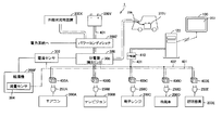
- FIG. 1 is a schematic diagram showing an overall configuration of a power management system 1 according to the present embodiment.
- the power management system 1 As shown in FIG. 1, the power management system 1 according to the present embodiment is installed in a house such as a house or an office. More specifically, the power management system 1 includes a plurality of home appliances as electric devices that consume power.
- FIG. 1 although not limited to these, as home appliances, an air conditioner (air conditioner) 200A, a television 200B, a microwave oven 200C, a refrigerator 200D, a lighting fixture 200E, and a water heater installed in a house. 200F (these are also collectively referred to as “home appliance 200”) and the like are illustrated.
- the power management system 1 also includes a solar power generation device 200X as an electric device that generates electric power, and a storage battery 200Y that stores and discharges electric power.
- the storage battery 200Y is for a house installed in a house or the like.
- the vehicle-mounted storage battery 200U connected via the vehicle-mounted storage battery connection part 306 is included.
- the in-vehicle storage battery 200U is normally mounted on an electric vehicle and used to drive the electric vehicle, and is connected to the power management system 1 according to this embodiment via the in-vehicle storage battery connection unit 306 for charging. . That is, the power management system 1 charges the in-vehicle storage battery 200U connected through the in-vehicle storage battery connection unit 306. However, for example, when there is an instruction operation from the user at the time of a power failure or the like, the in-vehicle storage battery 200U releases the electric power stored therein in the same manner as the residential storage battery 200Y. And electric power can be supplied to the household appliances 200.
- the power management system 1 is connected to a photovoltaic power generation apparatus 200X, a storage battery 200Y, a power system (such as commercial power provided by a power company), and a distribution board 300, and is a power conditioner for controlling each power. Including 200Z.
- the power conditioner 200Z balances the generated power from the solar power generation device 200X, the charge / discharge power with the storage battery 200Y, and the purchased power from the power system from the viewpoint of efficiency, and then through the distribution board 300. Then, power is supplied to each home appliance 200 through the connected power line 402.
- the distribution board 300 supplies power to the water heater 200F through another path branched from the power line 402.
- a current sensor 302 is provided between the distribution board 300 and the water heater 200F, and the electric power supplied to the water heater 200F can be measured using the current sensor 302.
- the water heater 200F is provided with a flow rate sensor 304 for measuring the flow rate discharged from the water heater 200F. By using the current sensor 302 and the flow sensor 304, the discharged flow rate can be converted into power consumption or power consumption.
- the distribution board 300 is provided with a current sensor 305, and it is possible to measure the current supplied to each home appliance 200 through the power line 402 and obtain the power supplied to each home appliance 200.
- the power management system 1 includes a repeater 410 for monitoring and controlling the measuring devices 400A to 400E, the solar power generation device 200X, the storage battery 200Y, the water heater 200F, the power conditioner 200Z, and the like associated with the home appliance 200.
- the home power management server 120 which is a power management device, and the management terminal 100 that acquires and displays display data from the home power management server 120 are included.
- the home power management server 120 includes measuring devices 400A to 400E, a current sensor 302, a flow sensor 304, a solar power generation device 200X, and a storage battery that are associated with the home appliance 200 via a wired or wireless network 401 and a repeater 410. Data communication is possible with the 200Y and the power conditioner 200Z.
- Any network 401 can be used.
- Ethernet registered trademark
- PLC Power Line Communications
- a physical dependency layer lower layer
- a wireless network for example, a wireless local area network (LAN), ZigBee (registered trademark), Bluetooth (registered trademark), or a red line communication system that conforms to the IEEE 802.11 standard can be used. Further, a plurality of communication methods may be combined.
- ZigBee registered trademark
- ECHONET Lite KNX, Z-Wave, or the like
- the measuring device (power measuring device) 400 is associated with one of the home appliances 200, measures information related to power consumption in the associated home appliance 200, and transmits the measurement information to the repeater 410.
- a power consumption measuring device that is disposed between the power line 402 and the plug of the home appliance 200 and measures the power consumption state is used.
- the measuring device 400 may be incorporated in each home appliance 200 and configured integrally with the home appliance 200.
- measuring instrument 400 may be configured integrally with a power socket provided on the house side.
- the hot water heater 200F is not associated with the measuring device 400, but the measurement results of the current sensor 302 and the flow rate sensor 304 are transmitted to the repeater 410 as described above. These measurement results are transmitted from the repeater 410 to the house power management server (power management apparatus) 120 and stored in the hard disk 109 provided in the house power management server 120.
- the home power management server 120 can obtain information on power consumption by converting into power consumption or power consumption based on the measurement results of these sensors.
- the management terminal (power information display device) 100 displays information provided by the house power management server 120 on the display (display unit) 103.
- measuring instruments 400A to 400E are electrically connected to the power line 402.
- Plug 250A of air conditioner 200A is connected to measuring instrument 400A
- plug 250B of television 200B is connected to measuring instrument 400B
- plug 250C of microwave oven 200C is connected to measuring instrument 400C
- the plug 250D of the refrigerator 200D is connected to the measuring device 400D
- the plug 250E of the lighting fixture 200E is connected to the measuring device 400E. Therefore, measuring instruments 400A to 400E measure information related to power consumption in air conditioner 200A, television 200B, microwave oven 200C, refrigerator 200D, and lighting fixture 200E, respectively.
- the household power management server 120 stores information related to power consumption transmitted from the measuring device 400 or the like associated with each home appliance 200 in the hard disk 129.
- the management terminal 100 communicates with the indoor power management server 120 and presents the state and information of the power management system 1 to the user, and receives an instruction regarding power management in the power management system 1 from the user. I will provide a.
- the management terminal 100 can display a graph or the like related to power consumption based on data provided from the house power management server 120.
- the home power management server 120 may provide a website, and the management terminal 100 may have a browser function to browse the website.
- the management terminal 100 may be portable, may be detachable from a base arranged on a table, or may be fixed to a wall of a room.
- a repeater 410 that collects data (not shown) and a home power management server 120 are provided, and the repeater 410 performs data communication with each of the measuring devices 400A to 400E. And the data of the electric power information which concern on the household appliances connected to those measuring devices are collected.
- the home power management server 120 acquires power information from each of the measuring devices 400A to 400E from the repeater 410 and accumulates it. Furthermore, the house power management server 120 calculates the usable time of the storage battery 200Y.
- the management terminal 100 acquires and displays the usable time calculated by the home power management server 120 and the display data provided by the home power management server 120.
- the management terminal 100 can also serve as a function of the home power management server 120 and can be configured to acquire data through data communication with each measuring instrument.
- the home power management server 120 acquires power information from each measuring device 400, but does not exchange with home appliances associated with these measuring devices 400.
- the house power management server 120 may acquire power information from each measuring device 400 and exchange with home appliances associated with these measuring devices 400.
- a part or preferably all of an air conditioner 200A, a television 200B, a microwave oven 200C, a refrigerator 200D, and a lighting fixture 200E are further connected to the network 401 shown in FIG. Furthermore, a water heater 200F may be connected.
- Each home appliance connected to the network 401 corresponds to the communication protocol used by the power management system 1 and can communicate with the home power management server 120 in the same manner as the measuring device 400. These communication protocols are, for example, ZigBee (registered trademark), ECHONET Lite, KNX, and Z-Wave.
- Household power management server 120 can control operations such as starting and stopping of the home appliances through communication, and can acquire the state of the home appliances.
- a hardware configuration of the house power management server 120 which is a main power management apparatus in that the power management system 1 shown in FIG. 1 is configured, will be described.
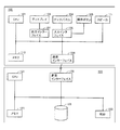
- FIG. 2 is a block diagram showing the hardware configuration of the home power management server 120 and the management terminal 100 according to the present embodiment.
- the management terminal 100 includes a CPU (Central Processing Unit) 101 that is a processor, a display 103 and a touch panel 104, operation buttons 105, a communication interface 106, an output interface 107, an input interface 108, A memory 110 and a speaker 111 are included.
- the home power management server 120 includes a CPU 121 as a processor, a clock 122, a memory 123, a communication interface 106, and a hard disk 129. The management terminal 100 and the home power management server 120 can exchange data via the respective communication interfaces 106 and 126.
- the CPU (processing unit) 101 of the management terminal 100 is a processing entity that controls the overall processing in the management terminal 100, and provides various functions as described below by executing a program stored in advance in the memory 110 or the like.
- the CPU 101 accepts a user operation input through the touch panel 104 or the operation button 105 and transmits the operation to the home power management server 120 via the communication interface 106.
- the display 103 and the touch panel 104 are devices that provide a user interface.
- the display 103 presents the display data received from the home power management server 120 to the user according to the command from the CPU 101.
- Touch panel 104 receives an operation performed by the user.
- the CPU 101 controls the operation received by the touch panel 104 to be transmitted to the household power management server 120.
- the display 103 includes, for example, an LCD (Liquid Crystal Display) or an organic EL (Electro Luminescence) display, and displays an image on the display surface.
- the touch panel 104 detects a touch operation with a user's finger or the like, and outputs a coordinate value indicating a position where the touch operation is performed to the CPU 101.
- touch panel 104 is provided in association with the display surface of display 103.
- the management terminal 100 does not necessarily include a touch panel, and it is sufficient if various information can be presented to the user.
- the operation buttons 105 are input means for accepting user operations, and typically one or a plurality of buttons are arranged on the surface of the management terminal 100.
- the operation button 105 includes a plurality of buttons and keys such as a determination button, a return button, a direction button, and a numeric keypad.
- the operation button 105 receives a user operation, the operation button 105 outputs information indicating the user operation to the CPU 101.
- the communication interface 106 (power information acquisition unit) performs data communication with the home power management server 120 in accordance with an instruction from the CPU 101. More specifically, the communication interface 106 includes, as described above, Ethernet (registered trademark), PLC (Power Line Communications), wireless LAN (Local Area Network) conforming to the IEEE 802.11 standard, ZigBee (registered trademark), Bluetooth (registered trademark), each red line communication method, and the like are used.
- Ethernet registered trademark
- PLC Power Line Communications
- wireless LAN Local Area Network
- ZigBee registered trademark
- Bluetooth registered trademark
- the output interface 107 mediates exchange of internal commands between the CPU 101 and the display 103.
- the input interface 108 mediates exchange of internal commands and / or signals between the touch panel 104 and / or the operation buttons 105 and the CPU 101.
- the memory 110 is implemented by a RAM (Random Access Memory) that is a volatile storage device, a flash ROM (Flash Read-Only Memory) that is a nonvolatile storage device, and the like. Stores work data required for execution.
- RAM Random Access Memory
- flash ROM Flash Read-Only Memory
- the speaker 111 is an audio device, and outputs audio according to a command from the CPU 101.
- the CPU (processing unit, information providing unit) 121 is a processing entity that controls overall processing in the home power management server 120.
- the CPU 121 provides various functions as a management device of the power management system 1 by executing a program stored in advance in the memory 123 or the like. That is, in response to the operation received from the management terminal 100, the process instructed by the user operation is executed.
- Such instructions include instructions for operation / stop for home appliance 200, instructions for changing the control mode for power conditioner 200Z, instructions for displaying the current or past power management state, and the like.
- the clock 122 is a time measuring unit, and responds to the CPU 121 with the current date and time according to a command from the CPU 121.
- the communication interface 126 (power information acquisition unit, operation acquisition unit) performs data communication with the management terminal 100, the measuring device 400, the solar power generation device 200X, the storage battery 200Y, the power conditioner 200Z, and the like according to instructions from the CPU 121. To do.
- the hard disk 129 stores various data necessary for information processing in the home power management server 120. Details of the various data will be described later.
- a semiconductor memory medium such as a flash memory, a mask ROM, an EPROM (Electronically Programmable Read-Only Memory), an EEPROM (Electronically Erasable Programmable Read-Only Memory), an IC (Integrated Circuit) card, a CD-ROM (Compact Disc-Read Only Memory) and optical disc storage media such as DVD-ROM (Digital Versatile Disk-Read Only Memory), magneto-optical disc storage media such as MO (Magnetic Optical Disc) and MD (Mini Disc), FD ( Magnetic storage media such as Flexible Disk), magnetic tape, and cassette tape can be used.
- a semiconductor memory medium such as a flash memory, a mask ROM, an EPROM (Electronically Programmable Read-Only Memory), an EEPROM (Electronically Erasable Programmable Read-Only Memory), an IC (Integrated Circuit) card, a CD
- Information processing in the home power management server 120 is realized by the CPU 121 executing a program in cooperation with peripheral hardware components. Generally, such a program is installed in advance in the memory 123 or the like.
- Such a program can be provided by being stored and distributed in an arbitrary storage medium.
- a program can be provided by downloading from a server device (or other device) connected to the Internet or the like. That is, the program stored in the storage medium is read out, or the program is acquired by downloading from the server device, and temporarily stored in the memory 123 or the like.
- the CPU 121 expands the program stored in the memory 123 into an executable format and then executes the program.
- Storage media for storing such programs include semiconductor storage media such as flash memory, mask ROM, EPROM, EEPROM, and IC card, optical disk storage media such as CD-ROM and DVD-ROM, and optical disks such as MO and MD.
- Magnetic storage media such as magnetic disk storage media, FD, magnetic tape, cassette tape, etc. can be used.
- the CPU 121 may read and execute the program stored in another system or apparatus.
- a program read from a storage medium or the like is written to a memory or the like mounted on a function expansion board or function expansion unit mounted on the computer, it is stored in the function expansion board or function expansion unit according to the program.
- the functions according to the present embodiment may be realized by performing all or part of necessary processing by a mounted arithmetic unit (CPU or the like).
- the CPU 121 executes not only all the functions according to the present embodiment by executing the program, but also all or part of processing that requires an OS (operating system) executed on the computer according to the program. By performing the above, the function according to the present embodiment may be realized.
- the program itself read from the storage medium or the like, or the storage medium storing the program constitutes one embodiment of the present embodiment. It will be.
- the program includes not only a program that can be directly executed by the CPU 121 but also a program in a source program format, a compressed program, and an encrypted program.
- FIG. 3 is an external view of a measuring instrument 400 according to the present embodiment.
- FIG. 3A shows a perspective view including the socket 4001 of the measuring instrument 400
- FIG. 3B shows a side view of the measuring instrument 400
- FIG. A perspective view including a plug 4002 of the container 400 is shown.
- measuring instrument 400 is arranged so as to be inserted between a socket for supplying power flowing through power line 402 and a plug of home appliance 200.
- a plug insertion socket 4001 is provided on one surface (front surface) of the measuring device 400.
- a plug 4002 is provided on the back surface of the measuring device 400 opposite to the front surface.
- the socket 4001 is plugged into the home appliance 200, and the plug 4002 is plugged into a socket (outlet / outlet) for supplying power via a power line 402 provided in the house.
- the measuring device 400 is preferably as thin as possible, and thus the width of the side surface is designed to be as small as possible.
- an LED 4041 and a setting button 4042 are provided on the front side of the measuring instrument 400.
- the LED 4041 displays a data processing state in the measuring device 400. More specifically, the LED 4041 varies the presence / absence of lighting and the presence / absence / cycle of blinking according to the data processing state. Note that the emission color may be changed instead of or in addition to the lighting and blinking display modes.
- the setting button 4042 is an input means for accepting a user operation. When the setting button 4042 is operated by the user, an initial setting in the measuring instrument 400 is started.
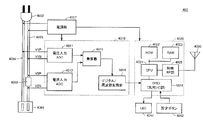
- FIG. 4 is a block diagram showing a hardware configuration of measuring instrument 400 according to the present embodiment.
- the measuring instrument 400 includes a pair of main wirings 4004 and 4005 that electrically connect the socket 4001 and the plug 4002, A shunt resistor 4003 inserted in the wiring 4005, a power supply unit 4007, a power detection unit 4010, a communication module 4020, and an antenna 4030 are included.
- the power detection unit 4010 detects power flowing from the plug 4002 to the socket 4001. More specifically, the power detection unit 4010 includes a voltage input ADC (Analog-to-Digital Converter) 4011, a current input ADC 4012, a multiplier 4013, and a digital / frequency conversion unit 4014.
- ADC Analog-to-Digital Converter
- the voltage input ADC 4011 is connected to the main wirings 4004 and 4005 via the wirings V1P and V1N, respectively.
- the voltage input ADC 4011 outputs a digital signal indicating a voltage (potential difference) generated between the main wirings to the multiplier 4013.
- the current input ADC 4012 is electrically connected to both ends of the shunt resistor 4003 inserted in the main wiring 4005 via the wirings V2P and V2N.
- the shunt resistor 4003 is a minute (several hundred micro ⁇ ) resistor used for measuring a flowing current value.
- the current input ADC 4012 outputs a digital signal indicating the current value of the current flowing through the shunt resistor 4003 to the multiplier 4013.
- the multiplier 4013 multiplies the digital signal (voltage value) from the voltage input ADC 4011 by the digital signal (current value) from the current input ADC 4012, and a value obtained as a result (power consumption / unit: W or kW). Is output to the digital / frequency converter 4014.
- the digital / frequency conversion unit 4014 converts the digital signal from the multiplier 4013 into a frequency signal and outputs the resulting frequency signal to the communication module 4020.
- the power supply unit 4007 supplies power to each component of the measuring device 400.
- the power supply unit 4007 is connected to the main wirings 4004 and 4005, and uses part of the power flowing from the plug 4002 to the socket 4001 as power for operation of the measuring device 400.
- the power supply unit 4007 converts the AC power into DC power, and then supplies the DC power to the power detection unit 4010 and the communication module 4020.
- the communication module 4020 transmits a radio signal indicating the power consumption in the electric device connected to the socket 4001 calculated by the power detection unit 4010 via the antenna 4030. More specifically, the communication module 4020 includes a CPU 4021, a ROM 4022, a RAM 4023, a GPIO (General Purpose Input / Output) 4024, and a radio RF (Radio Frequency) unit 4025.
- the GPIO 4024 receives the frequency signal input from the digital / frequency conversion unit 4014, and outputs information on the frequency signal to the CPU 4021.
- the CPU 4021 converts the frequency signal information from the GPIO 4024 according to a predetermined logic, and outputs the result to the wireless RF unit 4025.
- the wireless RF unit 4025 generates a wireless signal by modulating a carrier wave based on a data conversion result from the CPU 4021.
- a radio signal generated by the radio RF unit 4025 is transmitted to the repeater 410 via the antenna 4030.
- the CPU 4021 implements the processing as described above by executing a program stored in advance in the ROM 4022.
- the RAM 4023 stores work data necessary for the CPU 4021 to execute the program.
- the measuring device 400 basically measures the power consumption (unit: W or kW) consumed by the connected electrical device. By integrating the power consumption over a predetermined time, the power consumption amount (unit: Wh or kWh) of the electric device is calculated.
- the server 120 can display both the power consumption and the power consumption of each electric device on the display 103 of the management terminal 100. Further, a plurality of electric devices are grouped and the power consumption and power consumption for the entire group are displayed.
- the following is provided (however, the following example) Not limited to).
- the measuring device 400 measures the power consumption in the home appliance 200 every predetermined cycle (for example, every 5 seconds), and transmits the measured power consumption as measurement information in the same transmission cycle as the measurement cycle.
- the measuring device 400 measures the power consumption in the home appliance 200 every predetermined cycle (for example, every 5 seconds), and is measured between the previous transmission and the current transmission at a transmission cycle longer than the measurement cycle.
- the plurality of power consumptions are transmitted as measurement information.
- the measuring device 400 measures the power consumption in the home appliance 200 every predetermined cycle (for example, every 5 seconds), and is measured between the previous transmission and the current transmission at a transmission cycle longer than the measurement cycle.
- the average power consumption obtained by averaging the plurality of power consumptions is transmitted as measurement information.
- transmission is performed after adding a power consumption amount obtained by integrating a plurality of power consumptions measured from the previous transmission to the current transmission to the measurement information. Furthermore, you may add the average value, minimum value, maximum value, etc. of some power consumption.
- the home power management server 120 receives the measurement information from each measuring device 400 via the repeater 410. Upon reception, the time at that time is obtained from the clock 122 and stored in the hard disk 129 in association with the received measurement information.
- An arbitrary protocol can be adopted for exchanging measurement information between the home power management server 120 and the measuring device 400 via the repeater 410.
- a configuration is adopted in which measuring device 400 broadcasts a packet including its own measurement result, and repeater 410 receives this packet and notifies home power management server 120.
- the repeater 410 may periodically poll each measuring device 400.
- the home power management server 120 displays the usable time as an indication of how long the storage battery 200Y can supply energy on the display 103 of the management terminal 100.
- the available time is calculated based on the power information of the home appliances currently operating. The user can use the available time as a reference for determining which device is turned off and which device is turned on. Even if you do not actually perform the autonomous operation, you can simulate the autonomous operation to display the available time and use it as a reference for power saving. For example, it can be used as a reference for determining which home appliance to turn on to be self-sufficient (no power purchase).
- a typical self-sustained operation is executed when the power supply from the power system is cut off due to a power failure.
- the storage battery 200Y may be charged with the surplus power during the daytime when the solar power generation apparatus 200X generates a large amount of electricity during clear weather. Or what is necessary is just to charge the storage battery 200Y in the midnight time zone when electric power price is cheap.
- FIG. 5 is an explanatory diagram showing an example of a screen displayed on the display 103 of the management terminal 100 by the home power management server 120 according to the present embodiment.
- the screen of FIG. 5 is displayed during the autonomous operation and / or during the simulation of the autonomous operation.
- the screen shown in FIG. 5 is roughly divided into a storage battery information display field 510 in the left area and a device status display field 520 in the right area.
- a status bar 530 indicating the operation state of the management terminal 100 is displayed in the upper area of the screen, and a “home” button 531 and a “return” button 532 related to the screen change operation are displayed in the right area at the lower part of the screen. It is displayed.
- the CPU 101 of the management terminal 100 controls the home power management server 120 to notify the operation event that the “home” button 531 is touched.
- the CPU 121 of the house power management server 120 generates display data for an initial screen (not shown) in response to receiving the operation event. This is data of an initial screen (not shown) displayed on the display 103 of the management terminal 100. Then, the CPU 121 controls to transmit the generated display data to the management terminal 100.
- the CPU 121 of the home power management server 120 when the “return” button 532 is touched, the CPU 121 of the home power management server 120 generates display data of a screen (not shown) one level higher in response to receiving the operation event. To do. Then, control is performed to transmit the generated display data to the management terminal 100.
- each home appliance whose power information is measured by each measuring device 400 is displayed in a list together with the power information.
- four types of home appliances are displayed: an air conditioner, a television, a microwave oven, and a refrigerator. These correspond to the air conditioner 200A, the television 200B, the microwave oven 200C, and the refrigerator 200D shown in FIG. 1 is not shown in FIG. 5, it can be displayed using the scroll bar 521 at the right end. Furthermore, the water heater 200F may be displayed.
- home appliances to which power is not supplied from storage battery 200Y are not displayed in device status display field 520.
- the water heater 200F when power is not supplied to the water heater 200F during the independent operation, the water heater is not displayed.
- the microwave oven is not displayed in the device status display field 520.
- the home power management server 120 operates by receiving power from the storage battery 200Y during the independent operation. Therefore, the household power management server 120 may be displayed in the device status display field 520 as one of the home appliances.
- the current remaining amount of the storage battery 200Y is displayed as a percentage together with the illustration of the storage battery, and the usable time of the storage battery 200Y is further displayed.
- the remaining amount of the storage battery 200Y is displayed as 90%, and the usable time is displayed as about 16 hours.
- the battery 200Y is connected to the network 401, and information from the battery 200Y is sent to the home power management server 120 via the repeater 410. The remaining amount is sequentially updated based on information from the storage battery 200Y.
- the measuring instruments 400A to 400E send the power information of the corresponding home appliances to the home power management server 120.
- the current sensor 302 and the flow rate sensor 304 send information to the house power management server 120.
- the current sensor 305 sends information on the total current flowing into the house via the distribution board 300 to the house power management server 120.
- the home power management server 120 includes a power detection unit (not shown) that detects power consumed by the home power management server 120.
- the configuration of the power detection unit may be the same as that of the measuring device 400.
- the solar power generation device 200 ⁇ / b> X sends information related to the amount of power generation to the home power management server 120.
- the in-vehicle storage battery 200 ⁇ / b> U of the electric vehicle is connected to the in-vehicle storage battery connection unit 306, the in-vehicle storage battery 200 ⁇ / b> U sends information to the home power management server 120.
- These pieces of information may be sent in response to a request from the home power management server 120, or may be sent spontaneously by each device.
- the CPU 121 grasps the power supply / demand state of the power management system 1 based on the power information acquired from each device. And the usable time of the storage battery 200Y is estimated on the assumption that each household electrical appliance currently operating is continuously operated.
- the current power consumption of the air conditioner, television, microwave oven, and refrigerator is displayed.
- the air conditioner is operating and consuming 140W of power.
- the television is in operation and consumes 45W of power.
- the microwave oven is on standby and consumes 5W of power.
- the refrigerator is operating and consuming 25 W of power.
- the CPU 121 calculates the usable time when the current state continues, including the lighting fixture 200E and the indoor power management server 120 that are not displayed in FIG. 5, and displays them in the storage battery information display column 510.
- the CPU 121 of the household power management server 120 performs the following process in response to the reception of the operation event. First, the display of the touched home appliance is updated as the touched home appliance is excluded or selected from the target of independent operation. At the same time, the usable time of the storage battery 200Y is calculated again, and the display of the usable time is updated.
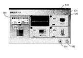
- FIG. 6 shows an example of a screen updated in response to an operation of the air conditioner icon on the screen shown in FIG.
- the icon of the air conditioner is grayed out and the message “Power OFF simulation is in progress” is superimposed and displayed.
- “36 hours” is displayed as the usable time in the storage battery information display field 510.
- this is a simulation value when the operation of the air conditioner is stopped, and it is also displayed that it is about 16 hours under the present condition that the air conditioner is operating.
- the simulation of turning off the power of the air conditioner is canceled and updated to the usable time in the current operation state. That is, the screen returns to the screen of FIG.
- the user can perform a simulation of the usable time assuming that each home appliance is individually operated and stopped. For example, when the user touches the icon of the microwave oven, the CPU 121 updates the available time assuming that the standby microwave oven is operated, and displays the result as a simulation value. It should be noted that the operation mode of each device may be set on the screen as well as the operation and stop simulation by touching the icon of each device.
- each home appliance is further connected to the network 401 and interacts with the home power management server 120.
- the CPU 121 may control the operation of the home appliance in response to the touch operation of the home appliance displayed in the device status display field 520.
- the management terminal 100 functions as a remote controller that remotely controls each home appliance.
- the available time is displayed as an available time based on the state of each device.
- the CPU 121 may be configured to select whether the CPU 121 controls the operation of the home appliance or simply performs a simulation in response to the touch operation.
- the CPU 121 calculates the usable time assuming that the current power generation amount continues.
- the power generation amount of the solar power generation device 200X varies depending on the amount of sunlight, that is, the weather and the time zone, it causes a decrease in the prediction accuracy of the usable time. Therefore, when predicting the usable time, it is preferable to calculate the usable time by averaging or predicting fluctuations based on the history of the power generation amount of the photovoltaic power generation apparatus 200X. Fluctuations in the amount of sunlight due to the cloud flow of the day are mitigated by averaging the power generation over the past several hours, and fluctuations in the amount of sunlight from sunrise to sunset average the power generation by time for the past several days. Can be predicted.
- the usable time may be calculated so that power is supplied to each home appliance only from the storage battery 200Y without including the solar power generation device 200X.
- an icon of the photovoltaic power generation apparatus 200X may be displayed in the device state display field 521. And you may make it switch whether the electric power generation amount by the solar power generation device 200X is considered for calculation of usable time by the touch operation to the icon of the solar power generation device 200X.
- the in-vehicle storage battery 200U charged to the in-vehicle storage battery connection unit 306 when the in-vehicle storage battery 200U charged to the in-vehicle storage battery connection unit 306 is connected, power may be supplied to each home appliance from the in-vehicle storage battery 200U in addition to the storage battery 200Y. The user may be allowed to switch whether or not to supply power to each home appliance from the in-vehicle storage battery 200U with the management terminal 100.
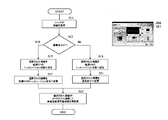
- FIG. 7 is a flowchart showing processing executed by the CPU 121 to display the screens of FIGS. 5 and 6.
- the upper right of FIG. 7 shows a reduced version of the screen of FIG. 6 for reference.
- the process will be described with reference to FIG.
- step S11 when the user touches the home appliance icon on the screen of FIG. 6, the operation event is sent to the home power management server 120.
- the CPU 121 of the household power management server 120 responds to it (step S11), and determines whether the touched icon is a normal display or a power-off simulation display (step S13). If it is a normal display (YES in step S13), since the selected home appliance is currently operating, the device is set as a target for power-off simulation (step S15). Then, the CPU 121 grays out the icon of the selected device and informs the user that it is in a power-off simulation state (step S17). Then, it is assumed that the selected home appliance is stopped, and the usable time of the storage battery 200Y is calculated according to the operation state of the device state display field 520 (step S23), and the usable time is displayed based on the calculation result. Update.
- step S13 If it is determined in step S13 that the touched icon is a power-off simulation (No in step S13), the CPU 121 assumes that the selected home appliance is operating (step S19). And the household appliances are changed into a normal display (step S21). Thereafter, the routine proceeds to step S23, calculates the usable time of the storage battery 200Y according to the operation state of the device state display field 520 (step S23), and updates the display of the usable time based on the calculation result.
- FIG. 9 and FIG. 10 are examples of screens different from those in FIG. 5, and are explanatory diagrams showing examples of screens considering the connection of the in-vehicle storage battery 200U.
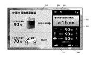
- FIG. 8 is an example of a state where the in-vehicle storage battery 200U is connected to the in-vehicle storage battery connection unit 306 but is not discharged.
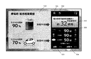
- FIG. 9 shows an example of a state where the in-vehicle storage battery 200U is discharged.
- FIG. 10 is an example of a state in which the in-vehicle storage battery is not connected to the in-vehicle storage battery connection unit 306.
- the screen shown in FIG. 8 is roughly composed of a storage battery information display column 510 on the left side area and a black frame area on the right side.
- the current battery remaining amount (percent display) and the state of charge / discharge are displayed together with an illustration of the storage battery 200Y.
- the remaining amount is 90%, and the storage battery 200Y is being discharged.
- the current remaining battery capacity and charge / discharge state of the in-vehicle storage battery 200U are displayed.
- the remaining amount is 70%, and charging / discharging is stopped. That is, FIG. 8 shows that the storage battery 200Y of the power management system 1 supplies power to each home appliance and is in a self-sustaining operation. There is no power supply from the in-vehicle storage battery 200U.
- a “home” button 531 and a “return” button 532 are arranged at the upper end of the black frame area on the right side.
- a storage battery information display field 510 is arranged in the lower window, and the usable time of the storage battery is displayed. In the example of FIG. 8, the usable time is predicted to be “about 16 hours”. Further below that is a device status display field 520.
- three icons of a television, a refrigerator, and LED lighting are displayed as home appliances. These correspond to the television 200B, the refrigerator 200D, and the lighting fixture 200E shown in FIG.
- the television consumes 90 W of power and is operating
- the refrigerator consumes 90 W of power and is operating
- the LED lighting consumes 50 W of power and is lit.
- the microwave oven 200 ⁇ / b> C and the air conditioner 200 ⁇ / b> A are not targets to which power is supplied from the storage battery. Therefore, it is not displayed in the storage battery information display column 510.
- three home appliances are displayed in FIG. 8, when power is supplied from the storage battery to three or more home appliances, other home appliances can be displayed using a scroll bar.
- a device power button 540 is displayed on the right side of each power device icon. By touching this button, each home appliance can be operated and stopped. It is assumed that each home appliance is connected to the network 401 and exchanges with the home power management server 120. That is, the CPU 121 controls the operation of the home appliance in response to a touch operation of the appliance power button 540 of the home appliance displayed in the appliance status display field 520. In the example shown in FIGS. 8 to 10, the operation of the device is stopped by touching the device power button 540 of each device, and the usable time of the storage battery is calculated and displayed according to the state of the device. As a modification, a control button for setting the operation mode of each device may be further displayed. Then, when the control button is touched, a menu set for each device may be displayed on the screen, and each device may be set using the menu.
- a “Stop” button 533 and a “Discharge” button 534 are further displayed for switching whether to supply power from the in-vehicle storage battery 200U during independent operation.
- These two buttons are alternatives, and when any one of the buttons is touched, the CPU 121 validates and maintains the state of the touched function in response to the touch operation.
- “stop” is effective, and power supply from the in-vehicle storage battery 200U is not performed during the autonomous operation.
- the characters “stopped” displayed on the right side of the illustration of the electric vehicle indicate this state.
- FIG. 9 shows an example of a screen updated in response to an operation when the “discharge” button 534 is touched on the screen shown in FIG.
- the word “in discharge” is displayed on the right side of the illustration of the electric vehicle, and the usable time in the storage battery information display column 510 on the right side is updated from 16 hours to 32 hours.
- a message “battery available time (storage battery + in-vehicle storage battery)” is displayed thereon, indicating that power is being supplied from the storage battery 200Y and the in-vehicle storage battery 200U.
- FIG. 10 shows a state where the connection of the in-vehicle storage battery connection unit 306 is disconnected and charging / discharging from the in-vehicle storage battery 200U is stopped.
- the illustration portion of the electric vehicle is grayed out, a “stopped” state is displayed on the right side, and a “non-connected” message is superimposed and displayed.
- the usable time is only the storage battery 200Y, and the usable time is displayed as “about 16 hours” corresponding to the usable time.
- FIG. 11 is a flowchart showing processing executed by the CPU 121 in response to the operation of the device power button 540 shown in FIG. Processing will be described with reference to FIG.
- the operation event is sent to the house power management server 120.
- the CPU 121 of the house power management server 120 responds (step S51) and performs the following process. That is, the lamp illustration displayed on the device power button 540 of the selected device is turned on or off (step S53). Then, the operation and stop of the home electric appliance are controlled according to the operation of the device power button 540 (step S55).
- a procedure for the CPU 121 to calculate the usable time of the storage battery will be described.
- the CPU 121 sequentially calculates the usable time of the storage battery. The calculation may be executed at a predetermined interval, but may be executed repeatedly even if the interval is not set. In one example, the usable time is calculated at intervals of about 5 seconds. This is because each measuring device 400 sends power information to the home power management server 120 at intervals of about 5 seconds.
- the CPU 121 calculates the usable time of the storage battery based on the following formula.
- Storage battery usable time (hours) Remaining capacity of storage battery (kilowatt hour) / Total power consumption of each home appliance (kilowatt)
- the remaining capacity of the storage battery shown in the above equation is acquired from the storage battery 200Y via the network 401.
- the in-vehicle storage battery 200U is connected to the in-vehicle storage battery connection unit 306, the remaining capacity is also acquired from the in-vehicle storage battery 200U.
- the in-vehicle storage battery 200U supplies power to each home appliance, the remaining capacities of the storage battery 200Y and the in-vehicle storage battery 200U are added together.
- the total power consumption of each home appliance may be the sum of the power information acquired from the measuring device 400. In this case, the power consumption at the moment when measuring instrument 400 measures each home electric appliance is added up. Therefore, when the operating state of each home appliance changes, the total power consumption changes accordingly.
- the power consumption history of each home appliance may be stored in the memory 123 or the hard disk 129 of the household power management server. And you may make it calculate the average electric power of the household appliance from each log
- the average power there are several patterns for obtaining the average power.
- the average power during the most recent hour, day, and month.
- Another pattern includes the average power of the same day of the same year, the average power of the same day of the same month, the average power of the previous day, the average power from the start of use of the home appliance to the present.
- the current value obtained from the current sensor 305 of the distribution board 300 and the voltage value obtained from the voltage input ADC (not shown) of the home power management server are used.
- the total power consumption may be obtained.
- the voltage input ADC is included in a power detection unit (not shown) of the home power management server.
- Power management system 100 Management terminal 101: CPU 103: Display 104: Touch panel 105: Operation button 106: Communication interface 107: Output interface 108: Input interface 110: Memory 111: Speaker 120: Home power management server 121: CPU 122: Clock 123: Memory 126: Communication interface 129: Hard disk 200: Home appliance 200A: Air conditioner 200B: Television 200C: Microwave oven 200D: Refrigerator 200E: Lighting apparatus 200F: Water heater 200U: Onboard storage battery 200X: Solar power generation device 200Y : Storage battery 200Z: Power conditioners 250A, 250B, 250C, 250D, 250E: Plug 300: Distribution board 302: Current sensor 304: Flow sensor 305: Current sensor 306: In-vehicle storage battery connection 400, 400A, 400B, 400C, 400D 400E: Measuring instrument 401: Network 402: Power line 4001: Socket 4002: Plug 4003: Shunt resistor 4004, 4005: Main wiring 4007: Power supply unit 4010: Power detection unit 4010:
Landscapes
- Physics & Mathematics (AREA)
- General Physics & Mathematics (AREA)
- Engineering & Computer Science (AREA)
- Manufacturing & Machinery (AREA)
- Chemical & Material Sciences (AREA)
- Chemical Kinetics & Catalysis (AREA)
- Electrochemistry (AREA)
- General Chemical & Material Sciences (AREA)
- Power Engineering (AREA)
- Remote Monitoring And Control Of Power-Distribution Networks (AREA)
- Charge And Discharge Circuits For Batteries Or The Like (AREA)
- Secondary Cells (AREA)
Priority Applications (1)
| Application Number | Priority Date | Filing Date | Title |
|---|---|---|---|
| US14/419,674 US9513340B2 (en) | 2012-08-07 | 2013-08-07 | Power information display device, power information display system and power information display method |
Applications Claiming Priority (2)
| Application Number | Priority Date | Filing Date | Title |
|---|---|---|---|
| JP2012175080A JP6072465B2 (ja) | 2012-08-07 | 2012-08-07 | 電力管理装置 |
| JP2012-175080 | 2012-08-07 |
Publications (1)
| Publication Number | Publication Date |
|---|---|
| WO2014024910A1 true WO2014024910A1 (ja) | 2014-02-13 |
Family
ID=50068133
Family Applications (1)
| Application Number | Title | Priority Date | Filing Date |
|---|---|---|---|
| PCT/JP2013/071332 Ceased WO2014024910A1 (ja) | 2012-08-07 | 2013-08-07 | 電力情報表示装置、電力情報表示システムおよび電力情報表示方法 |
Country Status (3)
| Country | Link |
|---|---|
| US (1) | US9513340B2 (enExample) |
| JP (1) | JP6072465B2 (enExample) |
| WO (1) | WO2014024910A1 (enExample) |
Cited By (3)
| Publication number | Priority date | Publication date | Assignee | Title |
|---|---|---|---|---|
| CN103926537A (zh) * | 2014-04-08 | 2014-07-16 | 可牛网络技术(北京)有限公司 | 一种电量信息的获取方法和电子设备 |
| CN104461846A (zh) * | 2014-12-02 | 2015-03-25 | 百度在线网络技术(北京)有限公司 | 检测应用程序耗电量的方法和装置 |
| CN106717074A (zh) * | 2014-09-26 | 2017-05-24 | 高通股份有限公司 | 设备到设备通信中的功率管理 |
Families Citing this family (26)
| Publication number | Priority date | Publication date | Assignee | Title |
|---|---|---|---|---|
| JP6227122B2 (ja) * | 2014-04-18 | 2017-11-08 | 三菱電機株式会社 | エネルギーマネジメントシステム、コントローラ、エネルギーマネジメント方法、及び、プログラム |
| JP2016063549A (ja) * | 2014-09-12 | 2016-04-25 | 株式会社東芝 | 負荷選択装置、負荷選択方法及びプログラム |
| JP6516287B2 (ja) * | 2015-03-24 | 2019-05-22 | Fdk株式会社 | 充電器 |
| JP6455820B2 (ja) * | 2015-03-26 | 2019-01-23 | パナソニックIpマネジメント株式会社 | 制御システム、制御装置、表示方法及び制御プログラム |
| JP6525661B2 (ja) * | 2015-03-26 | 2019-06-05 | 大阪瓦斯株式会社 | 電力供給システム |
| JP6292348B2 (ja) * | 2015-05-25 | 2018-03-14 | 富士電機株式会社 | 無停電電源装置および該装置の制御方法 |
| WO2016199815A1 (ja) * | 2015-06-08 | 2016-12-15 | 京セラ株式会社 | 通信装置、電力管理装置及び電力管理方法 |
| EP3322169A4 (en) * | 2015-07-08 | 2019-03-27 | Nec Corporation | INFORMATION PROCESSOR, INFORMATION PROCESSING SYSTEM, INFORMATION PROCESSING METHOD AND INFORMATION PROCESSING PROGRAM |
| JP6202407B2 (ja) * | 2016-01-22 | 2017-09-27 | オービタルワークス株式会社 | 無人飛行体 |
| JP6761969B2 (ja) * | 2016-07-05 | 2020-09-30 | パナソニックIpマネジメント株式会社 | 情報端末装置の制御方法、制御プログラム、及び情報表示システム |
| KR102610662B1 (ko) | 2016-09-15 | 2023-12-07 | 사반트 시스템즈, 인크. | 동적 나노 그리드들을 생성하고 에너지 시장에 참여하도록 전기 전력 소비자들을 집성하기 위한 시스템 및 방법들 |
| FR3064129B1 (fr) * | 2017-03-20 | 2022-06-24 | Continental Automotive France | Procede de gestion de la consommation electrique d'un equipement embarque dans un vehicule et connecte a une batterie |
| JP2018186426A (ja) * | 2017-04-27 | 2018-11-22 | レノボ・シンガポール・プライベート・リミテッド | ネットワークとの通信方法および携帯端末装置 |
| JP6622264B2 (ja) * | 2017-08-04 | 2019-12-18 | 矢崎総業株式会社 | 車載機器操作支援システム |
| WO2020218053A1 (ja) * | 2019-04-26 | 2020-10-29 | 株式会社Gsユアサ | 情報処理装置、情報処理システム、情報処理方法及びコンピュータプログラム |
| JP7222318B2 (ja) * | 2019-06-21 | 2023-02-15 | 株式会社村田製作所 | パワーコンディショナ |
| CN114616736A (zh) * | 2019-09-11 | 2022-06-10 | 萨万特系统公司 | 能量管理系统和方法 |
| US20210169740A1 (en) * | 2019-12-09 | 2021-06-10 | Thaddeus Medical Systems, Inc. | Medical transport container monitoring using machine learning |
| CN111668928A (zh) * | 2020-05-06 | 2020-09-15 | 许昌许继软件技术有限公司 | 一种用于电力保护装置的显示终端及方法 |
| JP7513455B2 (ja) * | 2020-07-28 | 2024-07-09 | 京セラ株式会社 | 機器管理装置、機器管理システム、及び機器管理方法 |
| US11934165B2 (en) * | 2020-10-28 | 2024-03-19 | Ubiquitous Energy, Inc. | Smart home system with integration of smart windows |
| JP2022138885A (ja) * | 2021-03-11 | 2022-09-26 | 恒栄電設株式会社 | 通知システム |
| JP2022148449A (ja) * | 2021-03-24 | 2022-10-06 | 住友電気工業株式会社 | 蓄電システム及びその自立運転方法 |
| JP7452490B2 (ja) * | 2021-05-18 | 2024-03-19 | 株式会社村田製作所 | 電力供給システム |
| JP7674182B2 (ja) * | 2021-07-26 | 2025-05-09 | シャープ株式会社 | 電力機器および自家電力管理システム |
| JP7170364B1 (ja) * | 2022-09-08 | 2022-11-14 | 株式会社石川エナジーリサーチ | 飛行装置 |
Citations (2)
| Publication number | Priority date | Publication date | Assignee | Title |
|---|---|---|---|---|
| JP2002062955A (ja) * | 2000-08-17 | 2002-02-28 | Casio Comput Co Ltd | 電池駆動端末装置、及び記憶媒体 |
| WO2011142330A1 (ja) * | 2010-05-11 | 2011-11-17 | 三洋電機株式会社 | 電力供給システム |
Family Cites Families (4)
| Publication number | Priority date | Publication date | Assignee | Title |
|---|---|---|---|---|
| JP3666307B2 (ja) * | 1999-06-30 | 2005-06-29 | 松下電器産業株式会社 | 二次電池の残量表示方法と二次電池の残量表示方法を備えた携帯型電子機器 |
| KR100395131B1 (ko) * | 2001-02-16 | 2003-08-21 | 삼성전자주식회사 | 스마트 배터리의 실제 잔류 용량을 표시하기 위한 장치 및방법 |
| JP5125303B2 (ja) | 2007-08-10 | 2013-01-23 | ソニー株式会社 | バッテリパック、電子機器、および残容量表示導出方法 |
| JP4410278B2 (ja) * | 2007-10-04 | 2010-02-03 | レノボ・シンガポール・プライベート・リミテッド | 電子機器、電子機器の電力制御方法、およびコンピュータが実行するためのプログラム |
-
2012
- 2012-08-07 JP JP2012175080A patent/JP6072465B2/ja active Active
-
2013
- 2013-08-07 US US14/419,674 patent/US9513340B2/en active Active
- 2013-08-07 WO PCT/JP2013/071332 patent/WO2014024910A1/ja not_active Ceased
Patent Citations (2)
| Publication number | Priority date | Publication date | Assignee | Title |
|---|---|---|---|---|
| JP2002062955A (ja) * | 2000-08-17 | 2002-02-28 | Casio Comput Co Ltd | 電池駆動端末装置、及び記憶媒体 |
| WO2011142330A1 (ja) * | 2010-05-11 | 2011-11-17 | 三洋電機株式会社 | 電力供給システム |
Cited By (4)
| Publication number | Priority date | Publication date | Assignee | Title |
|---|---|---|---|---|
| CN103926537A (zh) * | 2014-04-08 | 2014-07-16 | 可牛网络技术(北京)有限公司 | 一种电量信息的获取方法和电子设备 |
| CN106717074A (zh) * | 2014-09-26 | 2017-05-24 | 高通股份有限公司 | 设备到设备通信中的功率管理 |
| CN106717074B (zh) * | 2014-09-26 | 2020-05-19 | 高通股份有限公司 | 设备到设备通信中的功率管理 |
| CN104461846A (zh) * | 2014-12-02 | 2015-03-25 | 百度在线网络技术(北京)有限公司 | 检测应用程序耗电量的方法和装置 |
Also Published As
| Publication number | Publication date |
|---|---|
| US9513340B2 (en) | 2016-12-06 |
| JP6072465B2 (ja) | 2017-02-01 |
| JP2014036465A (ja) | 2014-02-24 |
| US20150185292A1 (en) | 2015-07-02 |
Similar Documents
| Publication | Publication Date | Title |
|---|---|---|
| JP6072465B2 (ja) | 電力管理装置 | |
| JP5353957B2 (ja) | 電力供給システム | |
| EP2779361B1 (en) | Power management device, control method and control program for power management device | |
| US20110210862A1 (en) | Method and apparatus for collecting and displaying consumption data from a meter reading system | |
| JP5575457B2 (ja) | 配電システム | |
| WO2012144474A1 (ja) | 制御装置、電力制御システム、及び電力制御方法 | |
| JP5845066B2 (ja) | 電力供給システム | |
| CN117121322A (zh) | 基于电器级电池的能量存储 | |
| JP5507527B2 (ja) | 電力管理装置、電力管理装置の制御方法および制御プログラム | |
| JP2014036466A (ja) | 電力管理装置および電力管理システム | |
| CA2755712A1 (en) | Energy management system incorporating a gas powered generator | |
| US11646584B2 (en) | Energy allocation system | |
| JPWO2013168814A1 (ja) | エネルギー管理装置、エネルギー管理方法およびプログラム | |
| JP2011160606A (ja) | 電力監視システム | |
| JP2018117455A (ja) | 消費電力量監視装置 | |
| JP2011160607A (ja) | 電力監視システム | |
| JP2013252007A (ja) | 電力管理装置および電力管理用プログラム | |
| JP5536012B2 (ja) | 管理システム、管理装置、管理プログラム、および管理方法 | |
| WO2009044126A2 (en) | System and method for monitoring utility consumption | |
| JP2014112989A (ja) | 電力計量情報中継装置、中継装置の設置場所決定方法及び電力計量情報通信方法 | |
| WO2011095856A2 (ja) | 電力監視システム | |
| EP2539812B1 (en) | An execution method of one function of a plurality of functions at a component | |
| CN201656562U (zh) | 一种智能电网智能计量控制终端装置 | |
| JP5740023B2 (ja) | 管理システム、管理装置および管理方法 | |
| JP2014068439A (ja) | コントローラ、コントローラの制御方法、制御プログラムおよび電力管理システム |
Legal Events
| Date | Code | Title | Description |
|---|---|---|---|
| 121 | Ep: the epo has been informed by wipo that ep was designated in this application |
Ref document number: 13827782 Country of ref document: EP Kind code of ref document: A1 |
|
| WWE | Wipo information: entry into national phase |
Ref document number: 14419674 Country of ref document: US |
|
| NENP | Non-entry into the national phase |
Ref country code: DE |
|
| 122 | Ep: pct application non-entry in european phase |
Ref document number: 13827782 Country of ref document: EP Kind code of ref document: A1 |