WO2014024910A1 - Device for displaying electrical power information, system for displaying electrical power information, and method for displaying electrical power information - Google Patents
Device for displaying electrical power information, system for displaying electrical power information, and method for displaying electrical power information Download PDFInfo
- Publication number
- WO2014024910A1 WO2014024910A1 PCT/JP2013/071332 JP2013071332W WO2014024910A1 WO 2014024910 A1 WO2014024910 A1 WO 2014024910A1 JP 2013071332 W JP2013071332 W JP 2013071332W WO 2014024910 A1 WO2014024910 A1 WO 2014024910A1
- Authority
- WO
- WIPO (PCT)
- Prior art keywords
- power
- storage battery
- information
- display
- usable time
- Prior art date
Links
Images


Classifications
-
- G—PHYSICS
- G01—MEASURING; TESTING
- G01R—MEASURING ELECTRIC VARIABLES; MEASURING MAGNETIC VARIABLES
- G01R31/00—Arrangements for testing electric properties; Arrangements for locating electric faults; Arrangements for electrical testing characterised by what is being tested not provided for elsewhere
- G01R31/36—Arrangements for testing, measuring or monitoring the electrical condition of accumulators or electric batteries, e.g. capacity or state of charge [SoC]
- G01R31/371—Arrangements for testing, measuring or monitoring the electrical condition of accumulators or electric batteries, e.g. capacity or state of charge [SoC] with remote indication, e.g. on external chargers
-
- G—PHYSICS
- G01—MEASURING; TESTING
- G01R—MEASURING ELECTRIC VARIABLES; MEASURING MAGNETIC VARIABLES
- G01R31/00—Arrangements for testing electric properties; Arrangements for locating electric faults; Arrangements for electrical testing characterised by what is being tested not provided for elsewhere
- G01R31/36—Arrangements for testing, measuring or monitoring the electrical condition of accumulators or electric batteries, e.g. capacity or state of charge [SoC]
- G01R31/382—Arrangements for monitoring battery or accumulator variables, e.g. SoC
- G01R31/3842—Arrangements for monitoring battery or accumulator variables, e.g. SoC combining voltage and current measurements
-
- H—ELECTRICITY
- H01—ELECTRIC ELEMENTS
- H01M—PROCESSES OR MEANS, e.g. BATTERIES, FOR THE DIRECT CONVERSION OF CHEMICAL ENERGY INTO ELECTRICAL ENERGY
- H01M10/00—Secondary cells; Manufacture thereof
- H01M10/42—Methods or arrangements for servicing or maintenance of secondary cells or secondary half-cells
- H01M10/48—Accumulators combined with arrangements for measuring, testing or indicating the condition of cells, e.g. the level or density of the electrolyte
- H01M10/488—Cells or batteries combined with indicating means for external visualization of the condition, e.g. by change of colour or of light density
-
- H—ELECTRICITY
- H02—GENERATION; CONVERSION OR DISTRIBUTION OF ELECTRIC POWER
- H02J—CIRCUIT ARRANGEMENTS OR SYSTEMS FOR SUPPLYING OR DISTRIBUTING ELECTRIC POWER; SYSTEMS FOR STORING ELECTRIC ENERGY
- H02J7/00—Circuit arrangements for charging or depolarising batteries or for supplying loads from batteries
- H02J7/0047—Circuit arrangements for charging or depolarising batteries or for supplying loads from batteries with monitoring or indicating devices or circuits
- H02J7/0048—Detection of remaining charge capacity or state of charge [SOC]
-
- G—PHYSICS
- G01—MEASURING; TESTING
- G01R—MEASURING ELECTRIC VARIABLES; MEASURING MAGNETIC VARIABLES
- G01R31/00—Arrangements for testing electric properties; Arrangements for locating electric faults; Arrangements for electrical testing characterised by what is being tested not provided for elsewhere
- G01R31/36—Arrangements for testing, measuring or monitoring the electrical condition of accumulators or electric batteries, e.g. capacity or state of charge [SoC]
- G01R31/367—Software therefor, e.g. for battery testing using modelling or look-up tables
-
- H—ELECTRICITY
- H01—ELECTRIC ELEMENTS
- H01M—PROCESSES OR MEANS, e.g. BATTERIES, FOR THE DIRECT CONVERSION OF CHEMICAL ENERGY INTO ELECTRICAL ENERGY
- H01M2220/00—Batteries for particular applications
- H01M2220/10—Batteries in stationary systems, e.g. emergency power source in plant
-
- Y—GENERAL TAGGING OF NEW TECHNOLOGICAL DEVELOPMENTS; GENERAL TAGGING OF CROSS-SECTIONAL TECHNOLOGIES SPANNING OVER SEVERAL SECTIONS OF THE IPC; TECHNICAL SUBJECTS COVERED BY FORMER USPC CROSS-REFERENCE ART COLLECTIONS [XRACs] AND DIGESTS
- Y02—TECHNOLOGIES OR APPLICATIONS FOR MITIGATION OR ADAPTATION AGAINST CLIMATE CHANGE
- Y02E—REDUCTION OF GREENHOUSE GAS [GHG] EMISSIONS, RELATED TO ENERGY GENERATION, TRANSMISSION OR DISTRIBUTION
- Y02E60/00—Enabling technologies; Technologies with a potential or indirect contribution to GHG emissions mitigation
- Y02E60/10—Energy storage using batteries
Definitions
- the present invention relates to a power management apparatus applied to a home power management system including a storage battery that can supply power to a plurality of electrical devices and a plurality of power measuring devices that respectively measure the power consumed by each electrical device.
- a battery-driven electric device generally has a function of notifying a user of how long a battery mounted on the electric device can operate.
- Various proposals have been made in relation to the functions.
- the following battery packs are known for the purpose of making the device user more correctly recognize the display of the rechargeable battery remaining capacity.
- the current integrated value representing the battery capacity is reset to the reference integrated value.
- the threshold corresponding to the reference integrated value and the remaining battery capacity of zero is corrected according to the degree of deterioration based on the number of times the battery is charged.
- the storage battery can save power in the power system by independent operation, and can function as an uninterruptible power supply in the event of a power failure.
- the capacity of the storage battery is finite. Therefore, the user will want to know the usable time of the storage battery during the self-sustaining operation. In particular, in the event of a power failure, if the energy stored in the storage battery runs out, the electrical equipment will stop, so it is particularly important to inform the available time.
- the present invention relates to a power information acquisition unit that acquires information related to a remaining capacity of a storage battery and information related to power consumption of a device that uses the power of the storage battery, and use of the storage battery when a plurality of devices are operating.
- a power information display device comprising: a display unit that displays a possible time and a usable time when at least one of the plurality of devices is stopped.
- this invention acquires the information regarding the remaining capacity of a storage battery, and the information regarding the power consumption of the apparatus using the electric power of the said storage battery, and the usable time of the said storage battery when the some apparatus is operate
- the present invention provides a method for displaying power information, which calculates a usable time when at least one of the plurality of devices is stopped and displays it on a display unit.
- a power information display device capable of estimating the usable time of a storage battery according to the operating state of an electrical device in a home when performing independent operation without receiving power supply from an electric power system. it can.
- FIG. 10 is an explanatory diagram showing a screen in a state further different from FIG. 9. It is a flowchart which shows the process with respect to operation of the apparatus power button shown in FIG.
- a power information display device comprising: a display unit that displays a usable time of a storage battery and a usable time when at least one of the plurality of devices is stopped.
- the display unit uses the same usable time based on the power of the storage battery when a plurality of devices are operating, and the usable time when at least one of the plurality of devices is stopped. Can be displayed on the screen.
- the display unit displays the usable time of the storage battery when a plurality of devices are operating and the usable time when at least one of the plurality of devices is stopped. Can be displayed according to the state.
- the display unit can selectively display a state where a plurality of devices are operating and a state where they are stopped, and can display them on the same screen as the usable time.
- the information regarding the remaining capacity of a storage battery the information regarding the power consumption of the apparatus using the electric power of the said storage battery, the power information acquisition part which acquires, the information regarding the remaining capacity of the said storage battery, and the information regarding the power consumption of the said apparatus At least one of the plurality of devices calculated using the usable time of the storage battery when the plurality of devices calculated using the information, the information on the remaining capacity of the storage battery and the information on the power consumption of the device are calculated.
- a power information display device including a display unit that displays a usable time when one is stopped.
- the display unit can selectively display a display indicating that it is assumed to be operating and a display indicating that it is assumed to be stopped for each of a plurality of devices, Can be displayed on the same screen as available time.
- a display device is provided.
- a power information display system includes a storage battery, a power measuring device that measures information related to power consumption of a device that uses the power of the storage battery, and the power information display device.
- the information on the remaining capacity of the storage battery and the information on the power consumption of the device using the power of the storage battery are acquired, and the usable time of the storage battery when a plurality of devices are operating And a power information display method for calculating an available time when at least one of the plurality of devices is stopped and displaying the calculated time on a display unit.
- the storage battery is applied to a home power management system including a storage battery that can supply power to a plurality of electrical devices and a plurality of power measuring devices that respectively measure the power consumed by each electrical device.
- Power information acquisition unit that sequentially acquires, as power information, the remaining capacity and power consumption of each electrical device from the storage battery and each power meter, and an operation acquisition unit that accepts selection by all or some of the plurality of electrical devices
- the storage battery sequentially calculates the usable time during which power can be supplied to the selected electrical device.
- a power management apparatus for a home power management system comprising a processing unit and an information providing unit for notifying a user of available time.
- the processing unit may calculate an available time of the storage battery and provide the information providing unit during a self-sustained operation in which power is supplied from the storage battery to each electric device without receiving power supply from an electric power system.
- the self-sustained operation refers to a state in which power is not supplied from the power system or is supplied from the storage battery to each electric device without receiving power.
- a state where not only the storage battery but also the power generated by the solar power generation device is supplied to each electric device is included in the independent operation.
- the operation acquisition unit acquires a selection and deselection operation for each electric device, and the processing unit can be used when the electric device is stopped when the selection of a certain electric device is cancelled.
- Time may be calculated and provided to the information providing unit. In this way, the usable time can be calculated by the selection and release operations without actually operating or stopping each electrical device.
- the processing unit is in a state where the selection of a certain electric device is released, but when the electric device is operating, the current operation is different from the state assumed in calculating the usable time for the electric device.
- the information providing unit may be controlled so as to inform the user. In this way, it is possible to notify the user that the actual state of each electrical device is different from the state of each electrical device used as a condition for calculating the usable time, and to prompt the user to take action.
- control unit may further include a control unit that communicates with each electrical device to control operation and stop of the electrical device, and the control unit performs electrical operation according to the operation of selecting and deselecting a certain electrical device.
- the device may be controlled to operate and stop. In this way, the electric device is operated and stopped in accordance with the operation of selecting and releasing the electric device, and the actual state of each electric device is matched with the state of each electric device as the condition for calculating the usable time. be able to.
- the vehicle storage battery connection unit for connecting the vehicle storage battery of the electric vehicle in parallel with the storage battery to serve as a power source for each electrical device, the operation acquisition unit, the vehicle storage battery is connected to the vehicle storage battery connection unit
- each electric device accepts an operation to enable and disable the power supply from the in-vehicle storage battery, and when the power supply from the in-vehicle storage battery is effective, the processing unit
- the storage battery may sequentially calculate the usable time during which power can be supplied to the selected electrical device. If it does in this way, similarly to the said storage battery, electric power can be supplied to each electric equipment from a vehicle-mounted storage battery, and the usable time according to it can be calculated and notified to a user.
- Preferred embodiments of the present invention include combinations of any of the plurality of embodiments shown here.
- the processing unit includes a storage battery that can supply power to a plurality of electrical devices, and a plurality of power measuring devices that respectively measure the power consumed by each electrical device. Since the storage battery sequentially calculates the available time during which the storage battery can supply power to the selected electrical device based on the power information about the selected electrical device and the remaining capacity of the storage battery, When the self-sustained operation is performed without receiving power supply from the grid, it is possible to estimate the usable time of the storage battery according to the operating state of the electrical equipment in the house.
- a storage battery is a storage battery that supplies electric power to a plurality of electric devices used in a house such as a house or office, not individual electric devices.
- the specific aspect is a lithium ion battery installed in order to store the electrical energy produced
- the household storage battery corresponds to a storage battery.
- the power measuring device is associated with one of the electric devices, measures information related to the power consumption of the electric device, and transmits the information to the indoor power management server.
- the specific mode is, for example, a power consumption measuring device that measures the power consumption of each electrical device in units of outlets.
- the usable time is a time during which the household storage battery can continue to supply power to the electrical device.
- the indoor power management system includes a power management device, and the power management device manages power information related to power consumption in at least one electrical device.
- the power management device manages power information related to power consumption in at least one electrical device.
- a photovoltaic power generation device, a fuel cell, or the like may be managed.
- the power management system according to the present embodiment generates power in addition to or in place of power consumption. You may manage the electric power information about.
- the power information is a concept including various information related to power consumption / power generation in a corresponding electric device (electric appliance).
- a power management system including one or more electric devices used in a house will be described as an example, but the embodiment of the present invention is not applied only to such a power management system. That is, the embodiment of the present invention can be applied to any configuration as long as it measures information related to power consumption using a measuring instrument or the like.
- an electric device is a concept that includes both a device that operates with electric power supplied from each unit and a device that generates electric power with some energy.
- Houses include houses and offices.
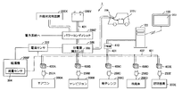
- FIG. 1 is a schematic diagram showing an overall configuration of a power management system 1 according to the present embodiment.
- the power management system 1 As shown in FIG. 1, the power management system 1 according to the present embodiment is installed in a house such as a house or an office. More specifically, the power management system 1 includes a plurality of home appliances as electric devices that consume power.
- FIG. 1 although not limited to these, as home appliances, an air conditioner (air conditioner) 200A, a television 200B, a microwave oven 200C, a refrigerator 200D, a lighting fixture 200E, and a water heater installed in a house. 200F (these are also collectively referred to as “home appliance 200”) and the like are illustrated.
- the power management system 1 also includes a solar power generation device 200X as an electric device that generates electric power, and a storage battery 200Y that stores and discharges electric power.
- the storage battery 200Y is for a house installed in a house or the like.
- the vehicle-mounted storage battery 200U connected via the vehicle-mounted storage battery connection part 306 is included.
- the in-vehicle storage battery 200U is normally mounted on an electric vehicle and used to drive the electric vehicle, and is connected to the power management system 1 according to this embodiment via the in-vehicle storage battery connection unit 306 for charging. . That is, the power management system 1 charges the in-vehicle storage battery 200U connected through the in-vehicle storage battery connection unit 306. However, for example, when there is an instruction operation from the user at the time of a power failure or the like, the in-vehicle storage battery 200U releases the electric power stored therein in the same manner as the residential storage battery 200Y. And electric power can be supplied to the household appliances 200.
- the power management system 1 is connected to a photovoltaic power generation apparatus 200X, a storage battery 200Y, a power system (such as commercial power provided by a power company), and a distribution board 300, and is a power conditioner for controlling each power. Including 200Z.
- the power conditioner 200Z balances the generated power from the solar power generation device 200X, the charge / discharge power with the storage battery 200Y, and the purchased power from the power system from the viewpoint of efficiency, and then through the distribution board 300. Then, power is supplied to each home appliance 200 through the connected power line 402.
- the distribution board 300 supplies power to the water heater 200F through another path branched from the power line 402.
- a current sensor 302 is provided between the distribution board 300 and the water heater 200F, and the electric power supplied to the water heater 200F can be measured using the current sensor 302.
- the water heater 200F is provided with a flow rate sensor 304 for measuring the flow rate discharged from the water heater 200F. By using the current sensor 302 and the flow sensor 304, the discharged flow rate can be converted into power consumption or power consumption.
- the distribution board 300 is provided with a current sensor 305, and it is possible to measure the current supplied to each home appliance 200 through the power line 402 and obtain the power supplied to each home appliance 200.
- the power management system 1 includes a repeater 410 for monitoring and controlling the measuring devices 400A to 400E, the solar power generation device 200X, the storage battery 200Y, the water heater 200F, the power conditioner 200Z, and the like associated with the home appliance 200.
- the home power management server 120 which is a power management device, and the management terminal 100 that acquires and displays display data from the home power management server 120 are included.
- the home power management server 120 includes measuring devices 400A to 400E, a current sensor 302, a flow sensor 304, a solar power generation device 200X, and a storage battery that are associated with the home appliance 200 via a wired or wireless network 401 and a repeater 410. Data communication is possible with the 200Y and the power conditioner 200Z.
- Any network 401 can be used.
- Ethernet registered trademark
- PLC Power Line Communications
- a physical dependency layer lower layer
- a wireless network for example, a wireless local area network (LAN), ZigBee (registered trademark), Bluetooth (registered trademark), or a red line communication system that conforms to the IEEE 802.11 standard can be used. Further, a plurality of communication methods may be combined.
- ZigBee registered trademark
- ECHONET Lite KNX, Z-Wave, or the like
- the measuring device (power measuring device) 400 is associated with one of the home appliances 200, measures information related to power consumption in the associated home appliance 200, and transmits the measurement information to the repeater 410.
- a power consumption measuring device that is disposed between the power line 402 and the plug of the home appliance 200 and measures the power consumption state is used.
- the measuring device 400 may be incorporated in each home appliance 200 and configured integrally with the home appliance 200.
- measuring instrument 400 may be configured integrally with a power socket provided on the house side.
- the hot water heater 200F is not associated with the measuring device 400, but the measurement results of the current sensor 302 and the flow rate sensor 304 are transmitted to the repeater 410 as described above. These measurement results are transmitted from the repeater 410 to the house power management server (power management apparatus) 120 and stored in the hard disk 109 provided in the house power management server 120.
- the home power management server 120 can obtain information on power consumption by converting into power consumption or power consumption based on the measurement results of these sensors.
- the management terminal (power information display device) 100 displays information provided by the house power management server 120 on the display (display unit) 103.
- measuring instruments 400A to 400E are electrically connected to the power line 402.
- Plug 250A of air conditioner 200A is connected to measuring instrument 400A
- plug 250B of television 200B is connected to measuring instrument 400B
- plug 250C of microwave oven 200C is connected to measuring instrument 400C
- the plug 250D of the refrigerator 200D is connected to the measuring device 400D
- the plug 250E of the lighting fixture 200E is connected to the measuring device 400E. Therefore, measuring instruments 400A to 400E measure information related to power consumption in air conditioner 200A, television 200B, microwave oven 200C, refrigerator 200D, and lighting fixture 200E, respectively.
- the household power management server 120 stores information related to power consumption transmitted from the measuring device 400 or the like associated with each home appliance 200 in the hard disk 129.
- the management terminal 100 communicates with the indoor power management server 120 and presents the state and information of the power management system 1 to the user, and receives an instruction regarding power management in the power management system 1 from the user. I will provide a.
- the management terminal 100 can display a graph or the like related to power consumption based on data provided from the house power management server 120.
- the home power management server 120 may provide a website, and the management terminal 100 may have a browser function to browse the website.
- the management terminal 100 may be portable, may be detachable from a base arranged on a table, or may be fixed to a wall of a room.
- a repeater 410 that collects data (not shown) and a home power management server 120 are provided, and the repeater 410 performs data communication with each of the measuring devices 400A to 400E. And the data of the electric power information which concern on the household appliances connected to those measuring devices are collected.
- the home power management server 120 acquires power information from each of the measuring devices 400A to 400E from the repeater 410 and accumulates it. Furthermore, the house power management server 120 calculates the usable time of the storage battery 200Y.
- the management terminal 100 acquires and displays the usable time calculated by the home power management server 120 and the display data provided by the home power management server 120.
- the management terminal 100 can also serve as a function of the home power management server 120 and can be configured to acquire data through data communication with each measuring instrument.
- the home power management server 120 acquires power information from each measuring device 400, but does not exchange with home appliances associated with these measuring devices 400.
- the house power management server 120 may acquire power information from each measuring device 400 and exchange with home appliances associated with these measuring devices 400.
- a part or preferably all of an air conditioner 200A, a television 200B, a microwave oven 200C, a refrigerator 200D, and a lighting fixture 200E are further connected to the network 401 shown in FIG. Furthermore, a water heater 200F may be connected.
- Each home appliance connected to the network 401 corresponds to the communication protocol used by the power management system 1 and can communicate with the home power management server 120 in the same manner as the measuring device 400. These communication protocols are, for example, ZigBee (registered trademark), ECHONET Lite, KNX, and Z-Wave.
- Household power management server 120 can control operations such as starting and stopping of the home appliances through communication, and can acquire the state of the home appliances.
- a hardware configuration of the house power management server 120 which is a main power management apparatus in that the power management system 1 shown in FIG. 1 is configured, will be described.
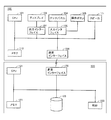
- FIG. 2 is a block diagram showing the hardware configuration of the home power management server 120 and the management terminal 100 according to the present embodiment.
- the management terminal 100 includes a CPU (Central Processing Unit) 101 that is a processor, a display 103 and a touch panel 104, operation buttons 105, a communication interface 106, an output interface 107, an input interface 108, A memory 110 and a speaker 111 are included.
- the home power management server 120 includes a CPU 121 as a processor, a clock 122, a memory 123, a communication interface 106, and a hard disk 129. The management terminal 100 and the home power management server 120 can exchange data via the respective communication interfaces 106 and 126.
- the CPU (processing unit) 101 of the management terminal 100 is a processing entity that controls the overall processing in the management terminal 100, and provides various functions as described below by executing a program stored in advance in the memory 110 or the like.
- the CPU 101 accepts a user operation input through the touch panel 104 or the operation button 105 and transmits the operation to the home power management server 120 via the communication interface 106.
- the display 103 and the touch panel 104 are devices that provide a user interface.
- the display 103 presents the display data received from the home power management server 120 to the user according to the command from the CPU 101.
- Touch panel 104 receives an operation performed by the user.
- the CPU 101 controls the operation received by the touch panel 104 to be transmitted to the household power management server 120.
- the display 103 includes, for example, an LCD (Liquid Crystal Display) or an organic EL (Electro Luminescence) display, and displays an image on the display surface.
- the touch panel 104 detects a touch operation with a user's finger or the like, and outputs a coordinate value indicating a position where the touch operation is performed to the CPU 101.
- touch panel 104 is provided in association with the display surface of display 103.
- the management terminal 100 does not necessarily include a touch panel, and it is sufficient if various information can be presented to the user.
- the operation buttons 105 are input means for accepting user operations, and typically one or a plurality of buttons are arranged on the surface of the management terminal 100.
- the operation button 105 includes a plurality of buttons and keys such as a determination button, a return button, a direction button, and a numeric keypad.
- the operation button 105 receives a user operation, the operation button 105 outputs information indicating the user operation to the CPU 101.
- the communication interface 106 (power information acquisition unit) performs data communication with the home power management server 120 in accordance with an instruction from the CPU 101. More specifically, the communication interface 106 includes, as described above, Ethernet (registered trademark), PLC (Power Line Communications), wireless LAN (Local Area Network) conforming to the IEEE 802.11 standard, ZigBee (registered trademark), Bluetooth (registered trademark), each red line communication method, and the like are used.
- Ethernet registered trademark
- PLC Power Line Communications
- wireless LAN Local Area Network
- ZigBee registered trademark
- Bluetooth registered trademark
- the output interface 107 mediates exchange of internal commands between the CPU 101 and the display 103.
- the input interface 108 mediates exchange of internal commands and / or signals between the touch panel 104 and / or the operation buttons 105 and the CPU 101.
- the memory 110 is implemented by a RAM (Random Access Memory) that is a volatile storage device, a flash ROM (Flash Read-Only Memory) that is a nonvolatile storage device, and the like. Stores work data required for execution.
- RAM Random Access Memory
- flash ROM Flash Read-Only Memory
- the speaker 111 is an audio device, and outputs audio according to a command from the CPU 101.
- the CPU (processing unit, information providing unit) 121 is a processing entity that controls overall processing in the home power management server 120.
- the CPU 121 provides various functions as a management device of the power management system 1 by executing a program stored in advance in the memory 123 or the like. That is, in response to the operation received from the management terminal 100, the process instructed by the user operation is executed.
- Such instructions include instructions for operation / stop for home appliance 200, instructions for changing the control mode for power conditioner 200Z, instructions for displaying the current or past power management state, and the like.
- the clock 122 is a time measuring unit, and responds to the CPU 121 with the current date and time according to a command from the CPU 121.
- the communication interface 126 (power information acquisition unit, operation acquisition unit) performs data communication with the management terminal 100, the measuring device 400, the solar power generation device 200X, the storage battery 200Y, the power conditioner 200Z, and the like according to instructions from the CPU 121. To do.
- the hard disk 129 stores various data necessary for information processing in the home power management server 120. Details of the various data will be described later.
- a semiconductor memory medium such as a flash memory, a mask ROM, an EPROM (Electronically Programmable Read-Only Memory), an EEPROM (Electronically Erasable Programmable Read-Only Memory), an IC (Integrated Circuit) card, a CD-ROM (Compact Disc-Read Only Memory) and optical disc storage media such as DVD-ROM (Digital Versatile Disk-Read Only Memory), magneto-optical disc storage media such as MO (Magnetic Optical Disc) and MD (Mini Disc), FD ( Magnetic storage media such as Flexible Disk), magnetic tape, and cassette tape can be used.
- a semiconductor memory medium such as a flash memory, a mask ROM, an EPROM (Electronically Programmable Read-Only Memory), an EEPROM (Electronically Erasable Programmable Read-Only Memory), an IC (Integrated Circuit) card, a CD
- Information processing in the home power management server 120 is realized by the CPU 121 executing a program in cooperation with peripheral hardware components. Generally, such a program is installed in advance in the memory 123 or the like.
- Such a program can be provided by being stored and distributed in an arbitrary storage medium.
- a program can be provided by downloading from a server device (or other device) connected to the Internet or the like. That is, the program stored in the storage medium is read out, or the program is acquired by downloading from the server device, and temporarily stored in the memory 123 or the like.
- the CPU 121 expands the program stored in the memory 123 into an executable format and then executes the program.
- Storage media for storing such programs include semiconductor storage media such as flash memory, mask ROM, EPROM, EEPROM, and IC card, optical disk storage media such as CD-ROM and DVD-ROM, and optical disks such as MO and MD.
- Magnetic storage media such as magnetic disk storage media, FD, magnetic tape, cassette tape, etc. can be used.
- the CPU 121 may read and execute the program stored in another system or apparatus.
- a program read from a storage medium or the like is written to a memory or the like mounted on a function expansion board or function expansion unit mounted on the computer, it is stored in the function expansion board or function expansion unit according to the program.
- the functions according to the present embodiment may be realized by performing all or part of necessary processing by a mounted arithmetic unit (CPU or the like).
- the CPU 121 executes not only all the functions according to the present embodiment by executing the program, but also all or part of processing that requires an OS (operating system) executed on the computer according to the program. By performing the above, the function according to the present embodiment may be realized.
- the program itself read from the storage medium or the like, or the storage medium storing the program constitutes one embodiment of the present embodiment. It will be.
- the program includes not only a program that can be directly executed by the CPU 121 but also a program in a source program format, a compressed program, and an encrypted program.
- FIG. 3 is an external view of a measuring instrument 400 according to the present embodiment.
- FIG. 3A shows a perspective view including the socket 4001 of the measuring instrument 400
- FIG. 3B shows a side view of the measuring instrument 400
- FIG. A perspective view including a plug 4002 of the container 400 is shown.
- measuring instrument 400 is arranged so as to be inserted between a socket for supplying power flowing through power line 402 and a plug of home appliance 200.
- a plug insertion socket 4001 is provided on one surface (front surface) of the measuring device 400.
- a plug 4002 is provided on the back surface of the measuring device 400 opposite to the front surface.
- the socket 4001 is plugged into the home appliance 200, and the plug 4002 is plugged into a socket (outlet / outlet) for supplying power via a power line 402 provided in the house.
- the measuring device 400 is preferably as thin as possible, and thus the width of the side surface is designed to be as small as possible.
- an LED 4041 and a setting button 4042 are provided on the front side of the measuring instrument 400.
- the LED 4041 displays a data processing state in the measuring device 400. More specifically, the LED 4041 varies the presence / absence of lighting and the presence / absence / cycle of blinking according to the data processing state. Note that the emission color may be changed instead of or in addition to the lighting and blinking display modes.
- the setting button 4042 is an input means for accepting a user operation. When the setting button 4042 is operated by the user, an initial setting in the measuring instrument 400 is started.
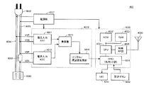
- FIG. 4 is a block diagram showing a hardware configuration of measuring instrument 400 according to the present embodiment.
- the measuring instrument 400 includes a pair of main wirings 4004 and 4005 that electrically connect the socket 4001 and the plug 4002, A shunt resistor 4003 inserted in the wiring 4005, a power supply unit 4007, a power detection unit 4010, a communication module 4020, and an antenna 4030 are included.
- the power detection unit 4010 detects power flowing from the plug 4002 to the socket 4001. More specifically, the power detection unit 4010 includes a voltage input ADC (Analog-to-Digital Converter) 4011, a current input ADC 4012, a multiplier 4013, and a digital / frequency conversion unit 4014.
- ADC Analog-to-Digital Converter
- the voltage input ADC 4011 is connected to the main wirings 4004 and 4005 via the wirings V1P and V1N, respectively.
- the voltage input ADC 4011 outputs a digital signal indicating a voltage (potential difference) generated between the main wirings to the multiplier 4013.
- the current input ADC 4012 is electrically connected to both ends of the shunt resistor 4003 inserted in the main wiring 4005 via the wirings V2P and V2N.
- the shunt resistor 4003 is a minute (several hundred micro ⁇ ) resistor used for measuring a flowing current value.
- the current input ADC 4012 outputs a digital signal indicating the current value of the current flowing through the shunt resistor 4003 to the multiplier 4013.
- the multiplier 4013 multiplies the digital signal (voltage value) from the voltage input ADC 4011 by the digital signal (current value) from the current input ADC 4012, and a value obtained as a result (power consumption / unit: W or kW). Is output to the digital / frequency converter 4014.
- the digital / frequency conversion unit 4014 converts the digital signal from the multiplier 4013 into a frequency signal and outputs the resulting frequency signal to the communication module 4020.
- the power supply unit 4007 supplies power to each component of the measuring device 400.
- the power supply unit 4007 is connected to the main wirings 4004 and 4005, and uses part of the power flowing from the plug 4002 to the socket 4001 as power for operation of the measuring device 400.
- the power supply unit 4007 converts the AC power into DC power, and then supplies the DC power to the power detection unit 4010 and the communication module 4020.
- the communication module 4020 transmits a radio signal indicating the power consumption in the electric device connected to the socket 4001 calculated by the power detection unit 4010 via the antenna 4030. More specifically, the communication module 4020 includes a CPU 4021, a ROM 4022, a RAM 4023, a GPIO (General Purpose Input / Output) 4024, and a radio RF (Radio Frequency) unit 4025.
- the GPIO 4024 receives the frequency signal input from the digital / frequency conversion unit 4014, and outputs information on the frequency signal to the CPU 4021.
- the CPU 4021 converts the frequency signal information from the GPIO 4024 according to a predetermined logic, and outputs the result to the wireless RF unit 4025.
- the wireless RF unit 4025 generates a wireless signal by modulating a carrier wave based on a data conversion result from the CPU 4021.
- a radio signal generated by the radio RF unit 4025 is transmitted to the repeater 410 via the antenna 4030.
- the CPU 4021 implements the processing as described above by executing a program stored in advance in the ROM 4022.
- the RAM 4023 stores work data necessary for the CPU 4021 to execute the program.
- the measuring device 400 basically measures the power consumption (unit: W or kW) consumed by the connected electrical device. By integrating the power consumption over a predetermined time, the power consumption amount (unit: Wh or kWh) of the electric device is calculated.
- the server 120 can display both the power consumption and the power consumption of each electric device on the display 103 of the management terminal 100. Further, a plurality of electric devices are grouped and the power consumption and power consumption for the entire group are displayed.
- the following is provided (however, the following example) Not limited to).
- the measuring device 400 measures the power consumption in the home appliance 200 every predetermined cycle (for example, every 5 seconds), and transmits the measured power consumption as measurement information in the same transmission cycle as the measurement cycle.
- the measuring device 400 measures the power consumption in the home appliance 200 every predetermined cycle (for example, every 5 seconds), and is measured between the previous transmission and the current transmission at a transmission cycle longer than the measurement cycle.
- the plurality of power consumptions are transmitted as measurement information.
- the measuring device 400 measures the power consumption in the home appliance 200 every predetermined cycle (for example, every 5 seconds), and is measured between the previous transmission and the current transmission at a transmission cycle longer than the measurement cycle.
- the average power consumption obtained by averaging the plurality of power consumptions is transmitted as measurement information.
- transmission is performed after adding a power consumption amount obtained by integrating a plurality of power consumptions measured from the previous transmission to the current transmission to the measurement information. Furthermore, you may add the average value, minimum value, maximum value, etc. of some power consumption.
- the home power management server 120 receives the measurement information from each measuring device 400 via the repeater 410. Upon reception, the time at that time is obtained from the clock 122 and stored in the hard disk 129 in association with the received measurement information.
- An arbitrary protocol can be adopted for exchanging measurement information between the home power management server 120 and the measuring device 400 via the repeater 410.
- a configuration is adopted in which measuring device 400 broadcasts a packet including its own measurement result, and repeater 410 receives this packet and notifies home power management server 120.
- the repeater 410 may periodically poll each measuring device 400.
- the home power management server 120 displays the usable time as an indication of how long the storage battery 200Y can supply energy on the display 103 of the management terminal 100.
- the available time is calculated based on the power information of the home appliances currently operating. The user can use the available time as a reference for determining which device is turned off and which device is turned on. Even if you do not actually perform the autonomous operation, you can simulate the autonomous operation to display the available time and use it as a reference for power saving. For example, it can be used as a reference for determining which home appliance to turn on to be self-sufficient (no power purchase).
- a typical self-sustained operation is executed when the power supply from the power system is cut off due to a power failure.
- the storage battery 200Y may be charged with the surplus power during the daytime when the solar power generation apparatus 200X generates a large amount of electricity during clear weather. Or what is necessary is just to charge the storage battery 200Y in the midnight time zone when electric power price is cheap.
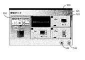
- FIG. 5 is an explanatory diagram showing an example of a screen displayed on the display 103 of the management terminal 100 by the home power management server 120 according to the present embodiment.
- the screen of FIG. 5 is displayed during the autonomous operation and / or during the simulation of the autonomous operation.
- the screen shown in FIG. 5 is roughly divided into a storage battery information display field 510 in the left area and a device status display field 520 in the right area.
- a status bar 530 indicating the operation state of the management terminal 100 is displayed in the upper area of the screen, and a “home” button 531 and a “return” button 532 related to the screen change operation are displayed in the right area at the lower part of the screen. It is displayed.
- the CPU 101 of the management terminal 100 controls the home power management server 120 to notify the operation event that the “home” button 531 is touched.
- the CPU 121 of the house power management server 120 generates display data for an initial screen (not shown) in response to receiving the operation event. This is data of an initial screen (not shown) displayed on the display 103 of the management terminal 100. Then, the CPU 121 controls to transmit the generated display data to the management terminal 100.
- the CPU 121 of the home power management server 120 when the “return” button 532 is touched, the CPU 121 of the home power management server 120 generates display data of a screen (not shown) one level higher in response to receiving the operation event. To do. Then, control is performed to transmit the generated display data to the management terminal 100.
- each home appliance whose power information is measured by each measuring device 400 is displayed in a list together with the power information.
- four types of home appliances are displayed: an air conditioner, a television, a microwave oven, and a refrigerator. These correspond to the air conditioner 200A, the television 200B, the microwave oven 200C, and the refrigerator 200D shown in FIG. 1 is not shown in FIG. 5, it can be displayed using the scroll bar 521 at the right end. Furthermore, the water heater 200F may be displayed.
- home appliances to which power is not supplied from storage battery 200Y are not displayed in device status display field 520.
- the water heater 200F when power is not supplied to the water heater 200F during the independent operation, the water heater is not displayed.
- the microwave oven is not displayed in the device status display field 520.
- the home power management server 120 operates by receiving power from the storage battery 200Y during the independent operation. Therefore, the household power management server 120 may be displayed in the device status display field 520 as one of the home appliances.
- the current remaining amount of the storage battery 200Y is displayed as a percentage together with the illustration of the storage battery, and the usable time of the storage battery 200Y is further displayed.
- the remaining amount of the storage battery 200Y is displayed as 90%, and the usable time is displayed as about 16 hours.
- the battery 200Y is connected to the network 401, and information from the battery 200Y is sent to the home power management server 120 via the repeater 410. The remaining amount is sequentially updated based on information from the storage battery 200Y.
- the measuring instruments 400A to 400E send the power information of the corresponding home appliances to the home power management server 120.
- the current sensor 302 and the flow rate sensor 304 send information to the house power management server 120.
- the current sensor 305 sends information on the total current flowing into the house via the distribution board 300 to the house power management server 120.
- the home power management server 120 includes a power detection unit (not shown) that detects power consumed by the home power management server 120.
- the configuration of the power detection unit may be the same as that of the measuring device 400.
- the solar power generation device 200 ⁇ / b> X sends information related to the amount of power generation to the home power management server 120.
- the in-vehicle storage battery 200 ⁇ / b> U of the electric vehicle is connected to the in-vehicle storage battery connection unit 306, the in-vehicle storage battery 200 ⁇ / b> U sends information to the home power management server 120.
- These pieces of information may be sent in response to a request from the home power management server 120, or may be sent spontaneously by each device.
- the CPU 121 grasps the power supply / demand state of the power management system 1 based on the power information acquired from each device. And the usable time of the storage battery 200Y is estimated on the assumption that each household electrical appliance currently operating is continuously operated.
- the current power consumption of the air conditioner, television, microwave oven, and refrigerator is displayed.
- the air conditioner is operating and consuming 140W of power.
- the television is in operation and consumes 45W of power.
- the microwave oven is on standby and consumes 5W of power.
- the refrigerator is operating and consuming 25 W of power.
- the CPU 121 calculates the usable time when the current state continues, including the lighting fixture 200E and the indoor power management server 120 that are not displayed in FIG. 5, and displays them in the storage battery information display column 510.
- the CPU 121 of the household power management server 120 performs the following process in response to the reception of the operation event. First, the display of the touched home appliance is updated as the touched home appliance is excluded or selected from the target of independent operation. At the same time, the usable time of the storage battery 200Y is calculated again, and the display of the usable time is updated.
- FIG. 6 shows an example of a screen updated in response to an operation of the air conditioner icon on the screen shown in FIG.
- the icon of the air conditioner is grayed out and the message “Power OFF simulation is in progress” is superimposed and displayed.
- “36 hours” is displayed as the usable time in the storage battery information display field 510.
- this is a simulation value when the operation of the air conditioner is stopped, and it is also displayed that it is about 16 hours under the present condition that the air conditioner is operating.
- the simulation of turning off the power of the air conditioner is canceled and updated to the usable time in the current operation state. That is, the screen returns to the screen of FIG.
- the user can perform a simulation of the usable time assuming that each home appliance is individually operated and stopped. For example, when the user touches the icon of the microwave oven, the CPU 121 updates the available time assuming that the standby microwave oven is operated, and displays the result as a simulation value. It should be noted that the operation mode of each device may be set on the screen as well as the operation and stop simulation by touching the icon of each device.
- each home appliance is further connected to the network 401 and interacts with the home power management server 120.
- the CPU 121 may control the operation of the home appliance in response to the touch operation of the home appliance displayed in the device status display field 520.
- the management terminal 100 functions as a remote controller that remotely controls each home appliance.
- the available time is displayed as an available time based on the state of each device.
- the CPU 121 may be configured to select whether the CPU 121 controls the operation of the home appliance or simply performs a simulation in response to the touch operation.
- the CPU 121 calculates the usable time assuming that the current power generation amount continues.
- the power generation amount of the solar power generation device 200X varies depending on the amount of sunlight, that is, the weather and the time zone, it causes a decrease in the prediction accuracy of the usable time. Therefore, when predicting the usable time, it is preferable to calculate the usable time by averaging or predicting fluctuations based on the history of the power generation amount of the photovoltaic power generation apparatus 200X. Fluctuations in the amount of sunlight due to the cloud flow of the day are mitigated by averaging the power generation over the past several hours, and fluctuations in the amount of sunlight from sunrise to sunset average the power generation by time for the past several days. Can be predicted.
- the usable time may be calculated so that power is supplied to each home appliance only from the storage battery 200Y without including the solar power generation device 200X.
- an icon of the photovoltaic power generation apparatus 200X may be displayed in the device state display field 521. And you may make it switch whether the electric power generation amount by the solar power generation device 200X is considered for calculation of usable time by the touch operation to the icon of the solar power generation device 200X.
- the in-vehicle storage battery 200U charged to the in-vehicle storage battery connection unit 306 when the in-vehicle storage battery 200U charged to the in-vehicle storage battery connection unit 306 is connected, power may be supplied to each home appliance from the in-vehicle storage battery 200U in addition to the storage battery 200Y. The user may be allowed to switch whether or not to supply power to each home appliance from the in-vehicle storage battery 200U with the management terminal 100.
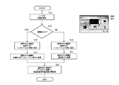
- FIG. 7 is a flowchart showing processing executed by the CPU 121 to display the screens of FIGS. 5 and 6.
- the upper right of FIG. 7 shows a reduced version of the screen of FIG. 6 for reference.
- the process will be described with reference to FIG.
- step S11 when the user touches the home appliance icon on the screen of FIG. 6, the operation event is sent to the home power management server 120.
- the CPU 121 of the household power management server 120 responds to it (step S11), and determines whether the touched icon is a normal display or a power-off simulation display (step S13). If it is a normal display (YES in step S13), since the selected home appliance is currently operating, the device is set as a target for power-off simulation (step S15). Then, the CPU 121 grays out the icon of the selected device and informs the user that it is in a power-off simulation state (step S17). Then, it is assumed that the selected home appliance is stopped, and the usable time of the storage battery 200Y is calculated according to the operation state of the device state display field 520 (step S23), and the usable time is displayed based on the calculation result. Update.
- step S13 If it is determined in step S13 that the touched icon is a power-off simulation (No in step S13), the CPU 121 assumes that the selected home appliance is operating (step S19). And the household appliances are changed into a normal display (step S21). Thereafter, the routine proceeds to step S23, calculates the usable time of the storage battery 200Y according to the operation state of the device state display field 520 (step S23), and updates the display of the usable time based on the calculation result.
- FIG. 9 and FIG. 10 are examples of screens different from those in FIG. 5, and are explanatory diagrams showing examples of screens considering the connection of the in-vehicle storage battery 200U.
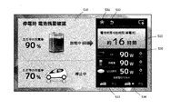
- FIG. 8 is an example of a state where the in-vehicle storage battery 200U is connected to the in-vehicle storage battery connection unit 306 but is not discharged.
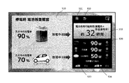
- FIG. 9 shows an example of a state where the in-vehicle storage battery 200U is discharged.
- FIG. 10 is an example of a state in which the in-vehicle storage battery is not connected to the in-vehicle storage battery connection unit 306.
- the screen shown in FIG. 8 is roughly composed of a storage battery information display column 510 on the left side area and a black frame area on the right side.
- the current battery remaining amount (percent display) and the state of charge / discharge are displayed together with an illustration of the storage battery 200Y.
- the remaining amount is 90%, and the storage battery 200Y is being discharged.
- the current remaining battery capacity and charge / discharge state of the in-vehicle storage battery 200U are displayed.
- the remaining amount is 70%, and charging / discharging is stopped. That is, FIG. 8 shows that the storage battery 200Y of the power management system 1 supplies power to each home appliance and is in a self-sustaining operation. There is no power supply from the in-vehicle storage battery 200U.
- a “home” button 531 and a “return” button 532 are arranged at the upper end of the black frame area on the right side.
- a storage battery information display field 510 is arranged in the lower window, and the usable time of the storage battery is displayed. In the example of FIG. 8, the usable time is predicted to be “about 16 hours”. Further below that is a device status display field 520.
- three icons of a television, a refrigerator, and LED lighting are displayed as home appliances. These correspond to the television 200B, the refrigerator 200D, and the lighting fixture 200E shown in FIG.
- the television consumes 90 W of power and is operating
- the refrigerator consumes 90 W of power and is operating
- the LED lighting consumes 50 W of power and is lit.
- the microwave oven 200 ⁇ / b> C and the air conditioner 200 ⁇ / b> A are not targets to which power is supplied from the storage battery. Therefore, it is not displayed in the storage battery information display column 510.
- three home appliances are displayed in FIG. 8, when power is supplied from the storage battery to three or more home appliances, other home appliances can be displayed using a scroll bar.
- a device power button 540 is displayed on the right side of each power device icon. By touching this button, each home appliance can be operated and stopped. It is assumed that each home appliance is connected to the network 401 and exchanges with the home power management server 120. That is, the CPU 121 controls the operation of the home appliance in response to a touch operation of the appliance power button 540 of the home appliance displayed in the appliance status display field 520. In the example shown in FIGS. 8 to 10, the operation of the device is stopped by touching the device power button 540 of each device, and the usable time of the storage battery is calculated and displayed according to the state of the device. As a modification, a control button for setting the operation mode of each device may be further displayed. Then, when the control button is touched, a menu set for each device may be displayed on the screen, and each device may be set using the menu.
- a “Stop” button 533 and a “Discharge” button 534 are further displayed for switching whether to supply power from the in-vehicle storage battery 200U during independent operation.
- These two buttons are alternatives, and when any one of the buttons is touched, the CPU 121 validates and maintains the state of the touched function in response to the touch operation.
- “stop” is effective, and power supply from the in-vehicle storage battery 200U is not performed during the autonomous operation.
- the characters “stopped” displayed on the right side of the illustration of the electric vehicle indicate this state.
- FIG. 9 shows an example of a screen updated in response to an operation when the “discharge” button 534 is touched on the screen shown in FIG.
- the word “in discharge” is displayed on the right side of the illustration of the electric vehicle, and the usable time in the storage battery information display column 510 on the right side is updated from 16 hours to 32 hours.
- a message “battery available time (storage battery + in-vehicle storage battery)” is displayed thereon, indicating that power is being supplied from the storage battery 200Y and the in-vehicle storage battery 200U.
- FIG. 10 shows a state where the connection of the in-vehicle storage battery connection unit 306 is disconnected and charging / discharging from the in-vehicle storage battery 200U is stopped.
- the illustration portion of the electric vehicle is grayed out, a “stopped” state is displayed on the right side, and a “non-connected” message is superimposed and displayed.
- the usable time is only the storage battery 200Y, and the usable time is displayed as “about 16 hours” corresponding to the usable time.
- FIG. 11 is a flowchart showing processing executed by the CPU 121 in response to the operation of the device power button 540 shown in FIG. Processing will be described with reference to FIG.
- the operation event is sent to the house power management server 120.
- the CPU 121 of the house power management server 120 responds (step S51) and performs the following process. That is, the lamp illustration displayed on the device power button 540 of the selected device is turned on or off (step S53). Then, the operation and stop of the home electric appliance are controlled according to the operation of the device power button 540 (step S55).
- a procedure for the CPU 121 to calculate the usable time of the storage battery will be described.
- the CPU 121 sequentially calculates the usable time of the storage battery. The calculation may be executed at a predetermined interval, but may be executed repeatedly even if the interval is not set. In one example, the usable time is calculated at intervals of about 5 seconds. This is because each measuring device 400 sends power information to the home power management server 120 at intervals of about 5 seconds.
- the CPU 121 calculates the usable time of the storage battery based on the following formula.
- Storage battery usable time (hours) Remaining capacity of storage battery (kilowatt hour) / Total power consumption of each home appliance (kilowatt)
- the remaining capacity of the storage battery shown in the above equation is acquired from the storage battery 200Y via the network 401.
- the in-vehicle storage battery 200U is connected to the in-vehicle storage battery connection unit 306, the remaining capacity is also acquired from the in-vehicle storage battery 200U.
- the in-vehicle storage battery 200U supplies power to each home appliance, the remaining capacities of the storage battery 200Y and the in-vehicle storage battery 200U are added together.
- the total power consumption of each home appliance may be the sum of the power information acquired from the measuring device 400. In this case, the power consumption at the moment when measuring instrument 400 measures each home electric appliance is added up. Therefore, when the operating state of each home appliance changes, the total power consumption changes accordingly.
- the power consumption history of each home appliance may be stored in the memory 123 or the hard disk 129 of the household power management server. And you may make it calculate the average electric power of the household appliance from each log
- the average power there are several patterns for obtaining the average power.
- the average power during the most recent hour, day, and month.
- Another pattern includes the average power of the same day of the same year, the average power of the same day of the same month, the average power of the previous day, the average power from the start of use of the home appliance to the present.
- the current value obtained from the current sensor 305 of the distribution board 300 and the voltage value obtained from the voltage input ADC (not shown) of the home power management server are used.
- the total power consumption may be obtained.
- the voltage input ADC is included in a power detection unit (not shown) of the home power management server.
- Power management system 100 Management terminal 101: CPU 103: Display 104: Touch panel 105: Operation button 106: Communication interface 107: Output interface 108: Input interface 110: Memory 111: Speaker 120: Home power management server 121: CPU 122: Clock 123: Memory 126: Communication interface 129: Hard disk 200: Home appliance 200A: Air conditioner 200B: Television 200C: Microwave oven 200D: Refrigerator 200E: Lighting apparatus 200F: Water heater 200U: Onboard storage battery 200X: Solar power generation device 200Y : Storage battery 200Z: Power conditioners 250A, 250B, 250C, 250D, 250E: Plug 300: Distribution board 302: Current sensor 304: Flow sensor 305: Current sensor 306: In-vehicle storage battery connection 400, 400A, 400B, 400C, 400D 400E: Measuring instrument 401: Network 402: Power line 4001: Socket 4002: Plug 4003: Shunt resistor 4004, 4005: Main wiring 4007: Power supply unit 4010: Power detection unit 4010:
Landscapes
- Physics & Mathematics (AREA)
- General Physics & Mathematics (AREA)
- Engineering & Computer Science (AREA)
- Manufacturing & Machinery (AREA)
- Chemical & Material Sciences (AREA)
- Chemical Kinetics & Catalysis (AREA)
- Electrochemistry (AREA)
- General Chemical & Material Sciences (AREA)
- Power Engineering (AREA)
- Remote Monitoring And Control Of Power-Distribution Networks (AREA)
- Secondary Cells (AREA)
- Charge And Discharge Circuits For Batteries Or The Like (AREA)
Abstract
Provided is a device for displaying electrical power information, equipped with: an electrical power information acquisition unit for acquiring information relating to the remaining capacity of a storage cell, and information relating to power consumed by devices that utilize power from the storage cell; and a display unit for displaying the available usage time of the storage cell in the event of operation of multiple devices, and the available usage time of the storage cell in the event that one or more of the multiple devices is halted.
Description
この発明は、複数の電気機器に電力を供給し得る蓄電池と、各電気機器が消費する電力をそれぞれ測定する複数の電力測定器とを含む家屋内電力管理システムに適用される電力管理装置に関する。
The present invention relates to a power management apparatus applied to a home power management system including a storage battery that can supply power to a plurality of electrical devices and a plurality of power measuring devices that respectively measure the power consumed by each electrical device.
バッテリー駆動される電気機器は、その電気機器に装着されたバッテリーであとどの程度の期間動作可能かをユーザに知らせる機能を一般に有している。
前記機能に関連して種々の提案がなされている。例えば、充電式バッテリー残容量の表示を機器のユーザに対してより正しく認識させることを目的とした、以下のバッテリーパックが知られている。充電時において順電電流が所定の値まで減少したことが検出されるとバッテリー容量を表す電流積算値を基準積算値にリセットする。さらに、前記基準積算値およびバッテリー残容量ゼロに対応する閾値をバッテリーの充電回数等に基づく劣化度に応じて補正する。 A battery-driven electric device generally has a function of notifying a user of how long a battery mounted on the electric device can operate.
Various proposals have been made in relation to the functions. For example, the following battery packs are known for the purpose of making the device user more correctly recognize the display of the rechargeable battery remaining capacity. When it is detected that the forward current has decreased to a predetermined value during charging, the current integrated value representing the battery capacity is reset to the reference integrated value. Furthermore, the threshold corresponding to the reference integrated value and the remaining battery capacity of zero is corrected according to the degree of deterioration based on the number of times the battery is charged.
また近年、環境問題や節電に対する意識が高まっている。これに伴い、有限な化石燃料に代えて太陽光、太陽熱、風力など、いわゆる再生可能エネルギーと呼ばれる自然のエネルギーを最大限に活かすように工夫した住宅やオフィスなどの家屋が注目されている。生活に伴う環境負担をできる限り減らそうとするものである。再生可能エネルギーのうちでも、特に太陽光発電は我々の身近で普及しつつある。さらに家屋全体として総合的に環境負担の低減を推し進めるように設計された住宅(エコハウス)が提案されている。
In recent years, awareness of environmental issues and power saving has increased. Along with this, houses such as houses and offices that have been devised to make the most of natural energy called renewable energy such as sunlight, solar heat, wind power, etc., instead of finite fossil fuels have attracted attention. We try to reduce the environmental burden associated with life as much as possible. Among renewable energies, in particular, photovoltaic power generation is becoming more popular around us. Furthermore, a house (eco-house) designed to promote a reduction in environmental burden as a whole house has been proposed.
太陽光発電をはじめとする自然エネルギーを利用して発電を行う場合、発電量は季節や一日の時間帯、地域等、自然条件により大きく変動する。発電量の変動は、消費量の変動と傾向が一致するものでない。そこで生成された電気エネルギーを有効に利用する観点から、蓄電池を備え、その電池に余剰のエネルギーを蓄えておく電力管理システムが提案されている。この電力管理システムでは、例えば昼の間に太陽光発電により生成された余剰の電気エネルギーを蓄電池に蓄えておく。日没後は電力系統から電力供給を受けずに蓄電池に蓄えたエネルギーを各電気機器に供給する自立運転を行って電力系統の消費電力を節約する。また、電力系統が停電したときは蓄電池に蓄えたエネルギーで各電気機器を駆動することができる。
When generating power using natural energy such as solar power generation, the amount of power generation varies greatly depending on the natural conditions such as season, time of day, and region. The fluctuation in power generation does not agree with the trend in consumption. Therefore, from the viewpoint of effectively using the generated electrical energy, a power management system that includes a storage battery and stores excess energy in the battery has been proposed. In this power management system, for example, surplus electrical energy generated by solar power generation during the daytime is stored in a storage battery. After sunset, the energy stored in the storage battery is not supplied with power from the power system, but is operated independently to save power consumption of the power system. In addition, when the power system fails, each electric device can be driven with the energy stored in the storage battery.
前述の家屋内電力管理システムにおいて、蓄電池は自立運転により電力系統の節電を可能にし、また、停電の場合は無停電電源装置として機能し得る。しかし、蓄電池の容量は有限である。よって、ユーザは自立運転時に蓄電池の使用可能時間を知りたいと考えるであろう。特に、停電時は蓄電池に蓄えられたエネルギーがなくなると電気機器が停止してしまうので、特に使用可能時間を知らせることが重要になる。
In the above-described home power management system, the storage battery can save power in the power system by independent operation, and can function as an uninterruptible power supply in the event of a power failure. However, the capacity of the storage battery is finite. Therefore, the user will want to know the usable time of the storage battery during the self-sustaining operation. In particular, in the event of a power failure, if the energy stored in the storage battery runs out, the electrical equipment will stop, so it is particularly important to inform the available time.
ところが、特許文献1のように機器に装着される蓄電池の場合は装着される機器のみを負荷として使用可能時間を推測すればよいが、複数の電気機器に電力を供給する蓄電池の場合は家屋内の種々の電気機器の動作状態によって負荷が変動する。使用可能時間の推測は各電気機器の動作状態を考慮して行わなければ実体と大きくかけ離れてしまう。
この発明は、以上のような事情を考慮してなされたものであって、電力系統から電力供給を受けずに自立運転する場合、家屋内の電気機器の動作状態に応じて蓄電池の使用可能時間を推測することが可能な電力情報表示装置を提供するものである。 However, in the case of a storage battery attached to a device as in Patent Document 1, it is only necessary to estimate the usable time using only the attached device as a load, but in the case of a storage battery that supplies power to a plurality of electrical devices, The load fluctuates depending on the operating state of the various electric devices. If the estimation of the usable time is not performed in consideration of the operating state of each electric device, it will be far from the substance.
The present invention has been made in consideration of the above circumstances, and in the case of independent operation without receiving power supply from the power system, the usable time of the storage battery according to the operating state of the electrical equipment in the house A power information display device capable of estimating the above is provided.
この発明は、蓄電池の残容量に関する情報と、前記蓄電池の電力を利用する機器の消費電力に関する情報と、を取得する電力情報取得部と、複数の機器が動作している場合の前記蓄電池の使用可能時間と、前記複数の機器のうちの少なくとも1つが停止している場合の使用可能時間とを表示する表示部と、を備えた電力情報表示装置を提供する。
The present invention relates to a power information acquisition unit that acquires information related to a remaining capacity of a storage battery and information related to power consumption of a device that uses the power of the storage battery, and use of the storage battery when a plurality of devices are operating. There is provided a power information display device comprising: a display unit that displays a possible time and a usable time when at least one of the plurality of devices is stopped.
また、この発明は、蓄電池の残容量に関する情報と、前記蓄電池の電力を利用する機器の消費電力に関する情報と、を取得し、複数の機器が動作している場合の前記蓄電池の使用可能時間と、前記複数の機器のうちの少なくとも1つが停止している場合の使用可能時間とを算出し、表示部に表示する、電力情報の表示方法を提供する。
Moreover, this invention acquires the information regarding the remaining capacity of a storage battery, and the information regarding the power consumption of the apparatus using the electric power of the said storage battery, and the usable time of the said storage battery when the some apparatus is operate | moving, and The present invention provides a method for displaying power information, which calculates a usable time when at least one of the plurality of devices is stopped and displays it on a display unit.
この発明によって、電力系統から電力供給を受けずに自立運転する場合、家庭内の電気機器の動作状態に応じて蓄電池の使用可能時間を推測することが可能な電力情報表示装置を提供することができる。
According to the present invention, it is possible to provide a power information display device capable of estimating the usable time of a storage battery according to the operating state of an electrical device in a home when performing independent operation without receiving power supply from an electric power system. it can.
以下、この発明の好ましい態様について説明する。
第一の好ましい態様では、蓄電池の残容量に関する情報と、前記蓄電池の電力を利用する機器の消費電力に関する情報と、を取得する電力情報取得部と、複数の機器が動作している場合の前記蓄電池の使用可能時間と、前記複数の機器のうちの少なくとも1つが停止している場合の使用可能時間とを表示する表示部と、を備えた電力情報表示装置を提供する。 Hereinafter, preferred embodiments of the present invention will be described.
In a first preferred embodiment, the information on the remaining capacity of the storage battery and the information on the power consumption of the device that uses the power of the storage battery, the power information acquisition unit that acquires the information, and the case where a plurality of devices are operating Provided is a power information display device comprising: a display unit that displays a usable time of a storage battery and a usable time when at least one of the plurality of devices is stopped.
また、前記表示部は、複数の機器が動作している場合の前記蓄電池の電力による使用可能時間と、前記複数の機器のうちの少なくとも1つが停止している場合の使用可能時間と、を同じ画面に表示できる。
Further, the display unit uses the same usable time based on the power of the storage battery when a plurality of devices are operating, and the usable time when at least one of the plurality of devices is stopped. Can be displayed on the screen.
さらに、前記表示部は、複数の機器が動作している場合の前記蓄電池の使用可能時間と、前記複数の機器のうちの少なくとも1つが停止している場合の使用可能時間と、を前記機器の状態に対応させて表示できる。
Furthermore, the display unit displays the usable time of the storage battery when a plurality of devices are operating and the usable time when at least one of the plurality of devices is stopped. Can be displayed according to the state.
あるいは、前記表示部は、複数の機器が動作している状態と停止している状態とを選択的に表示可能であり、前記使用可能時間と同じ画面に表示できる。
Alternatively, the display unit can selectively display a state where a plurality of devices are operating and a state where they are stopped, and can display them on the same screen as the usable time.
また、蓄電池の残容量に関する情報と、前記蓄電池の電力を利用する機器の消費電力に関する情報と、を取得する電力情報取得部と、前記蓄電池の残容量に関する情報と前記機器の消費電力に関する情報を用いて算出した複数の機器が動作している場合の前記蓄電池の使用可能時間と、前記蓄電池の残容量に関する情報と前記機器の消費電力に関する情報を用いて算出した前記複数の機器のうちの少なくとも1つが停止している場合の使用可能時間とを表示する表示部と、を備えた電力情報表示装置を提供する。
Moreover, the information regarding the remaining capacity of a storage battery, the information regarding the power consumption of the apparatus using the electric power of the said storage battery, the power information acquisition part which acquires, the information regarding the remaining capacity of the said storage battery, and the information regarding the power consumption of the said apparatus At least one of the plurality of devices calculated using the usable time of the storage battery when the plurality of devices calculated using the information, the information on the remaining capacity of the storage battery and the information on the power consumption of the device are calculated. Provided is a power information display device including a display unit that displays a usable time when one is stopped.
さらに、前記表示部は、複数の機器それぞれについて、動作している状態と仮定したことを示す表示と、停止している状態と仮定したことを示す表示とを選択的に表示可能であり、前記使用可能時間と同じ画面に表示できる。
Furthermore, the display unit can selectively display a display indicating that it is assumed to be operating and a display indicating that it is assumed to be stopped for each of a plurality of devices, Can be displayed on the same screen as available time.
あるいは、蓄電池の残容量に関する情報と、前記蓄電池の電力を利用する機器の消費電力に関する情報と、を取得する電力情報取得部と、複数の機器が動作している第一の状態の場合の前記蓄電池の使用可能時間と、前記第一の状態から前記複数の機器のうちの少なくとも1つが停止している第二の状態の場合の使用可能時間とを表示する表示部と、を備えた電力情報表示装置を提供する。
Alternatively, the information in the first state in which a plurality of devices are operating, and a power information acquisition unit that acquires information on the remaining capacity of the storage battery and information on power consumption of the device that uses the power of the storage battery Power information comprising: a display unit that displays a usable time of the storage battery and a usable time in a second state where at least one of the plurality of devices is stopped from the first state. A display device is provided.
さらに、蓄電池と、前記蓄電池の電力を利用する機器の消費電力に関する情報を測定する電力測定器と、上記の電力情報表示装置と、を備える電力情報表示システムを提供する。
Furthermore, a power information display system is provided that includes a storage battery, a power measuring device that measures information related to power consumption of a device that uses the power of the storage battery, and the power information display device.
第二の好ましい態様では、蓄電池の残容量に関する情報と、前記蓄電池の電力を利用する機器の消費電力に関する情報と、を取得し、複数の機器が動作している場合の前記蓄電池の使用可能時間と、前記複数の機器のうちの少なくとも1つが停止している場合の使用可能時間とを算出し、表示部に表示する、電力情報の表示方法を提供する。
In a second preferred embodiment, the information on the remaining capacity of the storage battery and the information on the power consumption of the device using the power of the storage battery are acquired, and the usable time of the storage battery when a plurality of devices are operating And a power information display method for calculating an available time when at least one of the plurality of devices is stopped and displaying the calculated time on a display unit.
第三の好ましい態様では、複数の電気機器に電力を供給し得る蓄電池と、各電気機器が消費する電力をそれぞれ測定する複数の電力測定器とを含む家屋内電力管理システムに適用され、前記蓄電池の残容量および各電気機器の電力消費を前記蓄電池および各電力測定器から電力情報として逐次取得する電力情報取得部と、前記複数の電気機器の全部または一部のユーザによる選択を受付ける操作取得部と、前記選択に応答し、選択された電気機器についての電力情報と前記蓄電池の残容量とに基づいて、前記蓄電池が、選択された前記電気機器に電力を供給できる使用可能時間を逐次算出する処理部と、使用可能時間をユーザに知らせる情報提供部とを備えることを特徴とする家屋内電力管理システム用の電力管理装置を提供する。
In a third preferred embodiment, the storage battery is applied to a home power management system including a storage battery that can supply power to a plurality of electrical devices and a plurality of power measuring devices that respectively measure the power consumed by each electrical device. Power information acquisition unit that sequentially acquires, as power information, the remaining capacity and power consumption of each electrical device from the storage battery and each power meter, and an operation acquisition unit that accepts selection by all or some of the plurality of electrical devices In response to the selection, based on the power information about the selected electrical device and the remaining capacity of the storage battery, the storage battery sequentially calculates the usable time during which power can be supplied to the selected electrical device. Provided is a power management apparatus for a home power management system, comprising a processing unit and an information providing unit for notifying a user of available time.
前記処理部は、電力系統から電力供給を受けず前記蓄電池から電力を各電気機器に供給する自立運転時に前記蓄電池の使用可能時間を算出し前記情報提供部に提供させてもよい。このようにすれば、実際に自立運転を行っているときに、各電気機器の動作状態に応じた使用可能時間を算出しユーザに知らせることができる。
ここで、自立運転は、電力系統から電力供給が受けられず、あるいは電力供給を受けないようにして蓄電池から各電気機器に供給する状態をいう。例えば、太陽光発電装置を備えた家屋内電力管理システムの場合、その蓄電池だけでなく太陽光発電装置が発電した電力を各電気機器に供給している状態も自立運転に含まれる。 The processing unit may calculate an available time of the storage battery and provide the information providing unit during a self-sustained operation in which power is supplied from the storage battery to each electric device without receiving power supply from an electric power system. In this way, the available time according to the operating state of each electrical device can be calculated and notified to the user during actual self-sustained operation.
Here, the self-sustained operation refers to a state in which power is not supplied from the power system or is supplied from the storage battery to each electric device without receiving power. For example, in the case of a house power management system equipped with a solar power generation device, a state where not only the storage battery but also the power generated by the solar power generation device is supplied to each electric device is included in the independent operation.
また、前記操作取得部は、各電気機器に対する選択および選択解除の操作を取得し、前記処理部はある電気機器の選択が解除されているとき、その電気機器を停止させるとした場合の使用可能時間を算出し前記情報提供部に提供させてもよい。このようにすれば、各電気機器を実際に動作または停止させなくても選択および解除の操作によって使用可能時間を算出することができる。
In addition, the operation acquisition unit acquires a selection and deselection operation for each electric device, and the processing unit can be used when the electric device is stopped when the selection of a certain electric device is cancelled. Time may be calculated and provided to the information providing unit. In this way, the usable time can be calculated by the selection and release operations without actually operating or stopping each electrical device.
さらに、前記処理部は、ある電気機器の選択が解除された状態にあるがその電気機器が動作しているとき、その電気機器について使用可能時間の算出において想定した状態と現在の動作が異なることをユーザに知らせるように前記情報提供部を制御してもよい。このようにすれば、各電気機器の実際の状態と使用可能時間の算出の条件とした各電気機器の状態が異なることをユーザに知らせてユーザに対処を促すことができる。
Further, the processing unit is in a state where the selection of a certain electric device is released, but when the electric device is operating, the current operation is different from the state assumed in calculating the usable time for the electric device. The information providing unit may be controlled so as to inform the user. In this way, it is possible to notify the user that the actual state of each electrical device is different from the state of each electrical device used as a condition for calculating the usable time, and to prompt the user to take action.
あるいは、各電気機器と通信してその電気機器の動作および停止を制御する制御部をさらに備え、前記制御部は、ある電気機器の選択および選択解除の操作がなされたときその操作に応じて電気機器を動作および停止させるように制御してもよい。このようにすれば、電気機器の選択および解除の操作に応じて電気機器を動作および停止させ、各電気機器の実際の状態と使用可能時間の算出の条件とした各電気機器の状態を一致させることができる。
Alternatively, the control unit may further include a control unit that communicates with each electrical device to control operation and stop of the electrical device, and the control unit performs electrical operation according to the operation of selecting and deselecting a certain electrical device. The device may be controlled to operate and stop. In this way, the electric device is operated and stopped in accordance with the operation of selecting and releasing the electric device, and the actual state of each electric device is matched with the state of each electric device as the condition for calculating the usable time. be able to.
また、前記蓄電池と並列に電気自動車の車載蓄電池を接続して各電気機器の電力源とするための車載蓄電池接続部をさらに備え、前記操作取得部は、前記車載蓄電池接続部に前記車載蓄電池が接続されているとき、各電気機器にその車載蓄電池からの電力供給を有効および無効にする操作を受付け、前記処理部は、前記車載蓄電池からの電力供給が有効なときは、前記蓄電池および前記車載蓄電池が、選択された前記電気機器に電力を供給できる使用可能時間を逐次算出するようにしてもよい。このようにすれば、前記蓄電池と同様に車載蓄電池から各電気機器に電力を供給しかつそれに応じた使用可能時間を算出してユーザに知らせることができる。
この発明の好ましい態様は、ここで示した複数の態様のうち何れかを組み合わせたものも含む。 In addition, the vehicle storage battery connection unit for connecting the vehicle storage battery of the electric vehicle in parallel with the storage battery to serve as a power source for each electrical device, the operation acquisition unit, the vehicle storage battery is connected to the vehicle storage battery connection unit When connected, each electric device accepts an operation to enable and disable the power supply from the in-vehicle storage battery, and when the power supply from the in-vehicle storage battery is effective, the processing unit The storage battery may sequentially calculate the usable time during which power can be supplied to the selected electrical device. If it does in this way, similarly to the said storage battery, electric power can be supplied to each electric equipment from a vehicle-mounted storage battery, and the usable time according to it can be calculated and notified to a user.
Preferred embodiments of the present invention include combinations of any of the plurality of embodiments shown here.
第三の好ましい態様において、処理部は、複数の電気機器に電力を供給し得る蓄電池と、各電気機器が消費する電力をそれぞれ測定する複数の電力測定器とを含む家屋内電力管理システムの電力管理装置に係り、選択された電気機器についての電力情報と前記蓄電池の残容量とに基づいて、前記蓄電池が、選択された前記電気機器に電力を供給できる使用可能時間を逐次算出するので、電力系統から電力供給を受けずに自立運転する場合、家屋内の電気機器の動作状態に応じて蓄電池の使用可能時間を推測することが可能である。
In a third preferred embodiment, the processing unit includes a storage battery that can supply power to a plurality of electrical devices, and a plurality of power measuring devices that respectively measure the power consumed by each electrical device. Since the storage battery sequentially calculates the available time during which the storage battery can supply power to the selected electrical device based on the power information about the selected electrical device and the remaining capacity of the storage battery, When the self-sustained operation is performed without receiving power supply from the grid, it is possible to estimate the usable time of the storage battery according to the operating state of the electrical equipment in the house.
蓄電池は、個別の電気機器ではなく住宅やオフィスなどの家屋で使用される複数の電気機器に電力を供給する蓄電池である。その具体的な態様は、例えば、太陽光発電装置により生成された電気エネルギーを蓄えておくために設置されるリチウムイオン電池である。後述する実施形態において、家庭用蓄電池は蓄電池に相当する。
A storage battery is a storage battery that supplies electric power to a plurality of electric devices used in a house such as a house or office, not individual electric devices. The specific aspect is a lithium ion battery installed in order to store the electrical energy produced | generated by the solar power generation device, for example. In the embodiment described later, the household storage battery corresponds to a storage battery.
また、電力測定器は、いずれかの電気機器に対応付けられ、その電気機器の電力消費に関する情報を測定して家屋内電力管理サーバに送信するものである。その具体的な態様は、例えば、個々の電気機器の消費電力をコンセント単位で測定する消費電力測定装置である。
また、使用可能時間は、家庭用蓄電池が電気機器に電力を供給し続けることのできる時間である。 The power measuring device is associated with one of the electric devices, measures information related to the power consumption of the electric device, and transmits the information to the indoor power management server. The specific mode is, for example, a power consumption measuring device that measures the power consumption of each electrical device in units of outlets.
The usable time is a time during which the household storage battery can continue to supply power to the electrical device.
以下、図面を用いてこの実施の態様をさらに詳述する。なお、以下の説明は、すべての点で例示であって、この実施の態様に限定するものと解されるべきではない。
Hereinafter, this embodiment will be described in more detail with reference to the drawings. In addition, the following description is an illustration in all the points, Comprising: It should not be construed to be limited to this embodiment.
<電力管理システムの構成>
本実施の形態による家屋内電力管理システムは、電力管理装置を含み、電力管理装置は、少なくとも1つの電気機器における電力消費に関する電力情報を管理する。なお、太陽光発電装置や燃料電池などを管理対象としてもよく、この場合には、本実施の形態による電力管理システムは、電力消費に関するに加えて、あるいは、電力消費に関するに代えて、電力発生に関する電力情報を管理してもよい。 <Configuration of power management system>
The indoor power management system according to the present embodiment includes a power management device, and the power management device manages power information related to power consumption in at least one electrical device. Note that a photovoltaic power generation device, a fuel cell, or the like may be managed. In this case, the power management system according to the present embodiment generates power in addition to or in place of power consumption. You may manage the electric power information about.
本明細書において、電力情報は、対応の電気機器(電気器具)における電力消費/電力発生に係るさまざまな情報を含む概念である。
In the present specification, the power information is a concept including various information related to power consumption / power generation in a corresponding electric device (electric appliance).
以下、家屋内で使用される1つまたは複数の電気機器を含む電力管理システムを一例として説明するが、本発明の実施の形態はこのような電力管理システムのみに適用されるものではない。すなわち、本発明の実施の形態は、測定器等を用いて電力消費に関する情報を測定するものであれば、どのような構成にも適用可能である。
Hereinafter, a power management system including one or more electric devices used in a house will be described as an example, but the embodiment of the present invention is not applied only to such a power management system. That is, the embodiment of the present invention can be applied to any configuration as long as it measures information related to power consumption using a measuring instrument or the like.
本明細書において、電気機器は、各部から供給される電力によって動作する機器、および、何らかのエネルギーによって発電する機器のいずれをも含む概念である。家屋は、住宅やオフィスなどを含む。
In this specification, an electric device is a concept that includes both a device that operates with electric power supplied from each unit and a device that generates electric power with some energy. Houses include houses and offices.
図1は、本実施の形態による電力管理システム1の全体構成を示す模式図である。
FIG. 1 is a schematic diagram showing an overall configuration of a power management system 1 according to the present embodiment.
図1に示すように、本実施の形態による電力管理システム1は、住宅やオフィスなどの家屋内に設置される。より具体的には、電力管理システム1は、電力を消費する電気機器として、複数の家電機器を含む。
As shown in FIG. 1, the power management system 1 according to the present embodiment is installed in a house such as a house or an office. More specifically, the power management system 1 includes a plurality of home appliances as electric devices that consume power.
図1には、これらに限られるものではないが、家電機器として、家屋内に設置されるエアコン(空気調和機)200A、テレビジョン200B、電子レンジ200C、冷蔵庫200D、および照明器具200E、給湯器200F(これらを「家電機器200」とも総称する。)などが図示されている。また、電力管理システム1は、電力を発生する電気機器としての太陽光発電装置200X、および電力の蓄電/放電を行なう蓄電池200Yを含む。蓄電池200Yは、住宅などに設置される家屋用のものである。さらに、車載蓄電池接続部306を介して接続される車載蓄電池200Uを含む。
In FIG. 1, although not limited to these, as home appliances, an air conditioner (air conditioner) 200A, a television 200B, a microwave oven 200C, a refrigerator 200D, a lighting fixture 200E, and a water heater installed in a house. 200F (these are also collectively referred to as “home appliance 200”) and the like are illustrated. The power management system 1 also includes a solar power generation device 200X as an electric device that generates electric power, and a storage battery 200Y that stores and discharges electric power. The storage battery 200Y is for a house installed in a house or the like. Furthermore, the vehicle-mounted storage battery 200U connected via the vehicle-mounted storage battery connection part 306 is included.
車載蓄電池200Uは、通常は電気自動車に搭載されてその電気自動車を駆動するために用いられ、充電のために車載蓄電池接続部306を介してこの実施の形態に係る電力管理システム1に接続される。即ち、電力管理システム1は車載蓄電池接続部306を介して接続された車載蓄電池200Uを充電する。
しかし、例えば停電時等にユーザから指示の操作があると、車載蓄電池200Uは、内部に蓄えられた電力を住宅用の蓄電池200Yと同様に放出する。そして、家電機器200に電力を供給することができる。 The in-vehicle storage battery 200U is normally mounted on an electric vehicle and used to drive the electric vehicle, and is connected to the power management system 1 according to this embodiment via the in-vehicle storage battery connection unit 306 for charging. . That is, the power management system 1 charges the in-vehicle storage battery 200U connected through the in-vehicle storage battery connection unit 306.
However, for example, when there is an instruction operation from the user at the time of a power failure or the like, the in-vehicle storage battery 200U releases the electric power stored therein in the same manner as the residential storage battery 200Y. And electric power can be supplied to the household appliances 200. FIG.
しかし、例えば停電時等にユーザから指示の操作があると、車載蓄電池200Uは、内部に蓄えられた電力を住宅用の蓄電池200Yと同様に放出する。そして、家電機器200に電力を供給することができる。 The in-
However, for example, when there is an instruction operation from the user at the time of a power failure or the like, the in-
さらに、電力管理システム1は、太陽光発電装置200X、蓄電池200Y、電力系統(電力会社が提供する商用電力など)と、分電盤300と接続され、それぞれの電力を制御するためのパワーコンディショナ200Zを含む。パワーコンディショナ200Zは、太陽光発電装置200Xからの発電電力、蓄電池200Yとの間の充放電電力、電力系統からの購入電力を、効率の観点からバランスさせた上で、分電盤300を介して接続された電力線402により各家電機器200へ電力を供給する。なお、分電盤300は、電力線402と分岐した別の経路で給湯機200Fに電力を供給する。分電盤300と給湯機200Fとの間には電流センサ302が設けられ、当該電流センサ302を用いて給湯機200Fに供給された電力を測定することが可能である。また、給湯機200Fには、給湯機200Fから排出された流量を計測するための流量センサ304が設けられている。
この電流センサ302と流量センサ304とを用いることにより排出された流量を消費電力あるいは消費電力量に換算することが可能である。
また、分電盤300には電流センサ305が設けられており、電力線402によって各家電機器200へ供給される電流を計測し、各家電機器200へ供給される電力を得ることが可能である。 Furthermore, the power management system 1 is connected to a photovoltaic power generation apparatus 200X, astorage battery 200Y, a power system (such as commercial power provided by a power company), and a distribution board 300, and is a power conditioner for controlling each power. Including 200Z. The power conditioner 200Z balances the generated power from the solar power generation device 200X, the charge / discharge power with the storage battery 200Y, and the purchased power from the power system from the viewpoint of efficiency, and then through the distribution board 300. Then, power is supplied to each home appliance 200 through the connected power line 402. The distribution board 300 supplies power to the water heater 200F through another path branched from the power line 402. A current sensor 302 is provided between the distribution board 300 and the water heater 200F, and the electric power supplied to the water heater 200F can be measured using the current sensor 302. In addition, the water heater 200F is provided with a flow rate sensor 304 for measuring the flow rate discharged from the water heater 200F.
By using thecurrent sensor 302 and the flow sensor 304, the discharged flow rate can be converted into power consumption or power consumption.
In addition, thedistribution board 300 is provided with a current sensor 305, and it is possible to measure the current supplied to each home appliance 200 through the power line 402 and obtain the power supplied to each home appliance 200.
この電流センサ302と流量センサ304とを用いることにより排出された流量を消費電力あるいは消費電力量に換算することが可能である。
また、分電盤300には電流センサ305が設けられており、電力線402によって各家電機器200へ供給される電流を計測し、各家電機器200へ供給される電力を得ることが可能である。 Furthermore, the power management system 1 is connected to a photovoltaic power generation apparatus 200X, a
By using the
In addition, the
さらに、電力管理システム1は、家電機器200に関連付けられた測定器400A~400E、太陽光発電装置200X、蓄電池200Y、給湯機200Fおよびパワーコンディショナ200Zなどを監視・制御するための中継器410、電力管理装置である家屋内電力管理サーバ120、家屋内電力管理サーバ120から表示データを取得して表示する管理端末100を含む。家屋内電力管理サーバ120は、有線または無線のネットワーク401および中継器410を介して、家電機器200に関連付けられた測定器400A~400E、電流センサ302、流量センサ304、太陽光発電装置200X、蓄電池200Y、およびパワーコンディショナ200Zなどとの間でデータ通信が可能である。
Furthermore, the power management system 1 includes a repeater 410 for monitoring and controlling the measuring devices 400A to 400E, the solar power generation device 200X, the storage battery 200Y, the water heater 200F, the power conditioner 200Z, and the like associated with the home appliance 200. The home power management server 120, which is a power management device, and the management terminal 100 that acquires and displays display data from the home power management server 120 are included. The home power management server 120 includes measuring devices 400A to 400E, a current sensor 302, a flow sensor 304, a solar power generation device 200X, and a storage battery that are associated with the home appliance 200 via a wired or wireless network 401 and a repeater 410. Data communication is possible with the 200Y and the power conditioner 200Z.
ネットワーク401としては、任意のものを利用することができる。有線のネットワークであれば、例えば、OSI基本参照モデルの物理層、データリンク層などいわゆる物理依存層(下位層)にあたるものとしてイーサネット(登録商標)、PLC(Power Line Communications)などを用いることができる。また、無線のネットワークであれば、例えば、IEEE802.11規格に準拠する無線LAN(Local Area Network)、ZigBee(登録商標)、Bluetooth(登録商標)、赤各線通信方式などを用いることができる。さらに、複数の通信方式を組み合わせてもよい。
さらに、OSI基本参照モデルの上位層にあたるものとして、例えば、ZigBee(登録商標)、ECHONET Lite、KNXやZ-Waveなどを用いることができる。 Anynetwork 401 can be used. In the case of a wired network, for example, Ethernet (registered trademark), PLC (Power Line Communications) or the like can be used as a physical dependency layer (lower layer) such as a physical layer or a data link layer of the OSI basic reference model. . For a wireless network, for example, a wireless local area network (LAN), ZigBee (registered trademark), Bluetooth (registered trademark), or a red line communication system that conforms to the IEEE 802.11 standard can be used. Further, a plurality of communication methods may be combined.
Furthermore, as an upper layer of the OSI basic reference model, for example, ZigBee (registered trademark), ECHONET Lite, KNX, Z-Wave, or the like can be used.
さらに、OSI基本参照モデルの上位層にあたるものとして、例えば、ZigBee(登録商標)、ECHONET Lite、KNXやZ-Waveなどを用いることができる。 Any
Furthermore, as an upper layer of the OSI basic reference model, for example, ZigBee (registered trademark), ECHONET Lite, KNX, Z-Wave, or the like can be used.
測定器(電力測定器)400は、いずれかの家電機器200に関連付けられ、当該関連付けられた家電機器200における電力消費に関する情報を測定するとともに、その測定情報を中継器410へ送信する。典型的には、測定器400としては、電力線402と家電機器200のプラグとの間に配置されて電力消費の状態を測定する消費電力測定装置が用いられる。異なる態様として、測定器400は、各家電機器200に組み込まれて家電機器200と一体に構成されてもよい。さらに異なる態様として、測定器400は、家屋側に設けられる電源ソケットと一体に構成されてもよい。
The measuring device (power measuring device) 400 is associated with one of the home appliances 200, measures information related to power consumption in the associated home appliance 200, and transmits the measurement information to the repeater 410. Typically, as the measuring instrument 400, a power consumption measuring device that is disposed between the power line 402 and the plug of the home appliance 200 and measures the power consumption state is used. As a different aspect, the measuring device 400 may be incorporated in each home appliance 200 and configured integrally with the home appliance 200. As a different aspect, measuring instrument 400 may be configured integrally with a power socket provided on the house side.
なお、給湯機200Fには、測定器400に関連付けられないが、上記したように電流センサ302および流量センサ304の測定結果が中継器410へ送信される。それらの測定結果は、中継器410から家屋内電力管理サーバ(電力管理装置)120へ送信されて家屋内電力管理サーバ120が備えるハードディスク109に蓄積される。家屋内電力管理サーバ120は、これらのセンサの測定結果に基づいて消費電力あるいは消費電力量に換算して、電力消費に関する情報を取得することが可能である。管理端末(電力情報表示装置)100は、家屋内電力管理サーバ120が提供する情報をディスプレイ(表示部)103に表示する。
Note that the hot water heater 200F is not associated with the measuring device 400, but the measurement results of the current sensor 302 and the flow rate sensor 304 are transmitted to the repeater 410 as described above. These measurement results are transmitted from the repeater 410 to the house power management server (power management apparatus) 120 and stored in the hard disk 109 provided in the house power management server 120. The home power management server 120 can obtain information on power consumption by converting into power consumption or power consumption based on the measurement results of these sensors. The management terminal (power information display device) 100 displays information provided by the house power management server 120 on the display (display unit) 103.
図1に示す例では、電力線402に5つの測定器400A~400Eが電気的に接続されている。測定器400Aには、エアコン200Aのプラグ250Aが接続されており、測定器400Bには、テレビジョン200Bのプラグ250Bが接続されており、測定器400Cには、電子レンジ200Cのプラグ250Cが接続されており、測定器400Dには、冷蔵庫200Dのプラグ250Dが接続されており、測定器400Eには、照明器具200Eのプラグ250Eが接続されている。そのため、測定器400A~400Eは、それぞれ、エアコン200A、テレビジョン200B、電子レンジ200C、冷蔵庫200D、照明器具200Eにおける電力消費に関する情報を測定する。
In the example shown in FIG. 1, five measuring devices 400A to 400E are electrically connected to the power line 402. Plug 250A of air conditioner 200A is connected to measuring instrument 400A, plug 250B of television 200B is connected to measuring instrument 400B, and plug 250C of microwave oven 200C is connected to measuring instrument 400C. The plug 250D of the refrigerator 200D is connected to the measuring device 400D, and the plug 250E of the lighting fixture 200E is connected to the measuring device 400E. Therefore, measuring instruments 400A to 400E measure information related to power consumption in air conditioner 200A, television 200B, microwave oven 200C, refrigerator 200D, and lighting fixture 200E, respectively.
なお、給湯器200Fについては、センサを用いて電力消費に関する情報を測定する。
家屋内電力管理サーバ120は、各家電機器200に関連付けられた測定器400等からそれぞれ送信される電力消費に関する情報をハードディスク129に格納する。 In addition, about thewater heater 200F, the information regarding power consumption is measured using a sensor.
The householdpower management server 120 stores information related to power consumption transmitted from the measuring device 400 or the like associated with each home appliance 200 in the hard disk 129.
家屋内電力管理サーバ120は、各家電機器200に関連付けられた測定器400等からそれぞれ送信される電力消費に関する情報をハードディスク129に格納する。 In addition, about the
The household
管理端末100は、家屋内電力管理サーバ120と通信し、電力管理システム1の状態や情報をユーザに提示したり、ユーザから電力管理システム1における電力管理に関する指示を受け付けたりするような、ユーザインターフェイスを提供する。
The management terminal 100 communicates with the indoor power management server 120 and presents the state and information of the power management system 1 to the user, and receives an instruction regarding power management in the power management system 1 from the user. I will provide a.
また、管理端末100は、家屋内電力管理サーバ120から提供されるデータに基づいて、電力消費に関するグラフ等を表示することも可能である。例えば家屋内電力管理サーバ120がウェブサイトを提供し、管理端末100がブラウザの機能を備えて前記ウェブサイトを閲覧するように構成してもよい。管理端末100は、ポータブル型であってもよいし、テーブル上に配置されたベースに対して着脱自在であってもよいし、部屋の壁などに固定されるものであってもよい。
Also, the management terminal 100 can display a graph or the like related to power consumption based on data provided from the house power management server 120. For example, the home power management server 120 may provide a website, and the management terminal 100 may have a browser function to browse the website. The management terminal 100 may be portable, may be detachable from a base arranged on a table, or may be fixed to a wall of a room.
本例においては、図示しないデータを収集する中継器410および家屋内電力管理サーバ120を設けて、中継器410が各測定器400A~400Eとデータ通信する。そして、それらの測定器に接続された家電機器に係る電力情報のデータを収集する。家屋内電力管理サーバ120は、中継器410からそれぞれの測定器400A~400Eから電力情報を取得して蓄積する。さらに、家屋内電力管理サーバ120は、蓄電池200Yの使用可能時間の計算を行う。管理端末100は、家屋内電力管理サーバ120により計算された使用可能時間および家屋内電力管理サーバ120が提供する表示データを取得して表示する。以上の構成の変形例として、管理端末100が家屋内電力管理サーバ120の機能を兼ね、各測定器とデータ通信してデータを取得する形態の構成とすることも可能である。
In this example, a repeater 410 that collects data (not shown) and a home power management server 120 are provided, and the repeater 410 performs data communication with each of the measuring devices 400A to 400E. And the data of the electric power information which concern on the household appliances connected to those measuring devices are collected. The home power management server 120 acquires power information from each of the measuring devices 400A to 400E from the repeater 410 and accumulates it. Furthermore, the house power management server 120 calculates the usable time of the storage battery 200Y. The management terminal 100 acquires and displays the usable time calculated by the home power management server 120 and the display data provided by the home power management server 120. As a modified example of the above configuration, the management terminal 100 can also serve as a function of the home power management server 120 and can be configured to acquire data through data communication with each measuring instrument.
また、図1に示す電力管理システム1では、家屋内電力管理サーバ120が各測定器400から電力情報を取得するが、それら測定器400に関連付けられた家電機器との遣り取りは行わない。この実施の形態の異なる構成として、家屋内電力管理サーバ120が各測定器400から電力情報を取得すると共に、それら測定器400に関連付けられた家電機器との遣り取りを行うものであってもよい。
Further, in the power management system 1 shown in FIG. 1, the home power management server 120 acquires power information from each measuring device 400, but does not exchange with home appliances associated with these measuring devices 400. As a different configuration of this embodiment, the house power management server 120 may acquire power information from each measuring device 400 and exchange with home appliances associated with these measuring devices 400.
この構成の場合、図1に示すネットワーク401にはさらにエアコン200A、テレビジョン200B、電子レンジ200C、冷蔵庫200Dおよび照明器具200Eの一部もしくは好ましくは全部が接続される。さらに、給湯器200Fが接続されてもよい。ネットワーク401に接続される各家電機器は、電力管理システム1が使用する通信プロトコルに対応し、測定器400と同様に家屋内電力管理サーバ120と通信できる。
それらの通信プロトコルは例えば、ZigBee(登録商標)、ECHONET Lite、KNXやZ-Waveである。家屋内電力管理サーバ120は、通信によりそれらの家電機器の起動、停止等の動作を制御することができ、また、それらの家電機器の状態を取得できる。
次に、図1に示す電力管理システム1を構成する点で主要な電力管理装置である家屋内電力管理サーバ120のハードウェア構成について説明する。 In the case of this configuration, a part or preferably all of anair conditioner 200A, a television 200B, a microwave oven 200C, a refrigerator 200D, and a lighting fixture 200E are further connected to the network 401 shown in FIG. Furthermore, a water heater 200F may be connected. Each home appliance connected to the network 401 corresponds to the communication protocol used by the power management system 1 and can communicate with the home power management server 120 in the same manner as the measuring device 400.
These communication protocols are, for example, ZigBee (registered trademark), ECHONET Lite, KNX, and Z-Wave. Householdpower management server 120 can control operations such as starting and stopping of the home appliances through communication, and can acquire the state of the home appliances.
Next, a hardware configuration of the housepower management server 120, which is a main power management apparatus in that the power management system 1 shown in FIG. 1 is configured, will be described.
それらの通信プロトコルは例えば、ZigBee(登録商標)、ECHONET Lite、KNXやZ-Waveである。家屋内電力管理サーバ120は、通信によりそれらの家電機器の起動、停止等の動作を制御することができ、また、それらの家電機器の状態を取得できる。
次に、図1に示す電力管理システム1を構成する点で主要な電力管理装置である家屋内電力管理サーバ120のハードウェア構成について説明する。 In the case of this configuration, a part or preferably all of an
These communication protocols are, for example, ZigBee (registered trademark), ECHONET Lite, KNX, and Z-Wave. Household
Next, a hardware configuration of the house
<家屋内電力管理サーバ120および管理端末100>
図2は、本実施の形態による家屋内電力管理サーバ120および管理端末100のハードウェア構成を示すブロック図である。 <In-housepower management server 120 and management terminal 100>
FIG. 2 is a block diagram showing the hardware configuration of the homepower management server 120 and the management terminal 100 according to the present embodiment.
図2は、本実施の形態による家屋内電力管理サーバ120および管理端末100のハードウェア構成を示すブロック図である。 <In-house
FIG. 2 is a block diagram showing the hardware configuration of the home
図2に示すように、管理端末100は、プロセッサであるCPU(Central ProcessingUnit)101と、ディスプレイ103およびタッチパネル104と、操作ボタン105と、通信インターフェイス106と、出力インターフェイス107と、入力インターフェイス108と、メモリ110と、スピーカー111とを含む。また、家屋内電力管理サーバ120は、プロセッサであるCPU121と、時計122と、メモリ123と、通信インターフェイス106と、ハードディスク129とを含む。管理端末100と家屋内電力管理サーバ120とは、それぞれの通信インターフェイス106および126を介してデータを遣り取りできる。
As shown in FIG. 2, the management terminal 100 includes a CPU (Central Processing Unit) 101 that is a processor, a display 103 and a touch panel 104, operation buttons 105, a communication interface 106, an output interface 107, an input interface 108, A memory 110 and a speaker 111 are included. The home power management server 120 includes a CPU 121 as a processor, a clock 122, a memory 123, a communication interface 106, and a hard disk 129. The management terminal 100 and the home power management server 120 can exchange data via the respective communication interfaces 106 and 126.
管理端末100のCPU(処理部)101は、管理端末100における全体処理を司る処理主体であり、メモリ110などに予め格納されたプログラムを実行することで、後述するような各種機能を提供する。CPU101は、タッチパネル104または操作ボタン105を入力されたユーザ操作を受付け、その操作を、通信インターフェイス106を介して家屋内電力管理サーバ120に送信する。
The CPU (processing unit) 101 of the management terminal 100 is a processing entity that controls the overall processing in the management terminal 100, and provides various functions as described below by executing a program stored in advance in the memory 110 or the like. The CPU 101 accepts a user operation input through the touch panel 104 or the operation button 105 and transmits the operation to the home power management server 120 via the communication interface 106.
ディスプレイ103およびタッチパネル104は、ユーザインターフェイスを提供する装置である。ディスプレイ103は、CPU101からの命令に従って家屋内電力管理サーバ120から受信した表示データをユーザに提示する。タッチパネル104は、ユーザが行った操作を受付ける。CPU101は、タッチパネル104が受付けた操作を家屋内電力管理サーバ120へ送信するように制御する。
The display 103 and the touch panel 104 are devices that provide a user interface. The display 103 presents the display data received from the home power management server 120 to the user according to the command from the CPU 101. Touch panel 104 receives an operation performed by the user. The CPU 101 controls the operation received by the touch panel 104 to be transmitted to the household power management server 120.
より具体的には、ディスプレイ103は、例えば、LCD(Liquid Crystal Display)や有機EL(Electro Luminescence)ディスプレイなどからなり、その表示面に画像を表示する。タッチパネル104は、ユーザの指などによるタッチ操作を検出して、そのタッチ操作がなされた位置を示す座標値などをCPU101へ出力する。本実施の形態においては、ディスプレイ103の表示面に対応付けてタッチパネル104が設けられている。但し、管理端末100は、必ずしもタッチパネルを含む必要はなく、ユーザに対して、各種情報を提示できればよい。
More specifically, the display 103 includes, for example, an LCD (Liquid Crystal Display) or an organic EL (Electro Luminescence) display, and displays an image on the display surface. The touch panel 104 detects a touch operation with a user's finger or the like, and outputs a coordinate value indicating a position where the touch operation is performed to the CPU 101. In the present embodiment, touch panel 104 is provided in association with the display surface of display 103. However, the management terminal 100 does not necessarily include a touch panel, and it is sufficient if various information can be presented to the user.
操作ボタン105は、ユーザ操作を受け付けるための入力手段であり、典型的には、管理端末100の表面に1つまたは複数が配置される。典型的に、操作ボタン105は、決定ボタン、戻りボタン、方向ボタン、テンキーなどの複数のボタンやキーを含む。操作ボタン105は、ユーザ操作を受け付けると、そのユーザ操作を示す情報をCPU101へ出力する。
The operation buttons 105 are input means for accepting user operations, and typically one or a plurality of buttons are arranged on the surface of the management terminal 100. Typically, the operation button 105 includes a plurality of buttons and keys such as a determination button, a return button, a direction button, and a numeric keypad. When the operation button 105 receives a user operation, the operation button 105 outputs information indicating the user operation to the CPU 101.
通信インターフェイス106(電力情報取得部)は、CPU101からの命令に従って、家屋内電力管理サーバ120との間でデータ通信を行なう。より具体的には、通信インターフェイス106は、上述したような、イーサネット(登録商標)、PLC(Power Line Communications)、IEEE802.11規格に準拠する無線LAN(Local Area Network)、ZigBee(登録商標)、Bluetooth(登録商標)、赤各線通信方式などを利用する。
The communication interface 106 (power information acquisition unit) performs data communication with the home power management server 120 in accordance with an instruction from the CPU 101. More specifically, the communication interface 106 includes, as described above, Ethernet (registered trademark), PLC (Power Line Communications), wireless LAN (Local Area Network) conforming to the IEEE 802.11 standard, ZigBee (registered trademark), Bluetooth (registered trademark), each red line communication method, and the like are used.
出力インターフェイス107は、CPU101とディスプレイ103との間の内部コマンドの遣り取りを仲介する。入力インターフェイス108は、タッチパネル104および/または操作ボタン105とCPU101との間の内部コマンドおよび/または信号の遣り取りを仲介する。
The output interface 107 mediates exchange of internal commands between the CPU 101 and the display 103. The input interface 108 mediates exchange of internal commands and / or signals between the touch panel 104 and / or the operation buttons 105 and the CPU 101.
メモリ110は、揮発性記憶装置であるRAM(Random Access Memory)や、不揮発性記憶装置であるフラッシュROM(Flash Read-Only Memory)などによって実現され、CPU101によって実行されるプログラムや、CPU101によるプログラムの実行に必要なワークデータを格納する。
The memory 110 is implemented by a RAM (Random Access Memory) that is a volatile storage device, a flash ROM (Flash Read-Only Memory) that is a nonvolatile storage device, and the like. Stores work data required for execution.
スピーカー111は、音声デバイスであり、CPU101からの命令に従って音声を出力する。
The speaker 111 is an audio device, and outputs audio according to a command from the CPU 101.
一方、CPU(処理部、情報提供部)121は、家屋内電力管理サーバ120における全体処理を司る処理主体である。CPU121は、メモリ123などに予め格納されたプログラムを実行することで、電力管理システム1の管理装置としての各種機能を提供する。即ち、管理端末100から受信した操作に応答して、当該ユーザ操作によって指示された処理を実行する。このような指示としては、家電機器200に対する運転/停止に関する指示、パワーコンディショナ200Zに対する制御モードの変更に関する指示、現在または過去の電力管理状態を表示する指示などを含む。
On the other hand, the CPU (processing unit, information providing unit) 121 is a processing entity that controls overall processing in the home power management server 120. The CPU 121 provides various functions as a management device of the power management system 1 by executing a program stored in advance in the memory 123 or the like. That is, in response to the operation received from the management terminal 100, the process instructed by the user operation is executed. Such instructions include instructions for operation / stop for home appliance 200, instructions for changing the control mode for power conditioner 200Z, instructions for displaying the current or past power management state, and the like.
時計122は、計時手段であり、CPU121からの命令に従って、現在の日付や時刻をCPU121へ応答する。
通信インターフェイス126(電力情報取得部、操作取得部)は、CPU121からの命令に従って、管理端末100、測定器400、太陽光発電装置200X、蓄電池200Y、およびパワーコンディショナ200Zなどとの間でデータ通信を行なう。 Theclock 122 is a time measuring unit, and responds to the CPU 121 with the current date and time according to a command from the CPU 121.
The communication interface 126 (power information acquisition unit, operation acquisition unit) performs data communication with themanagement terminal 100, the measuring device 400, the solar power generation device 200X, the storage battery 200Y, the power conditioner 200Z, and the like according to instructions from the CPU 121. To do.
通信インターフェイス126(電力情報取得部、操作取得部)は、CPU121からの命令に従って、管理端末100、測定器400、太陽光発電装置200X、蓄電池200Y、およびパワーコンディショナ200Zなどとの間でデータ通信を行なう。 The
The communication interface 126 (power information acquisition unit, operation acquisition unit) performs data communication with the
ハードディスク129は、家屋内電力管理サーバ120での情報処理に必要な各種データを格納する。この各種データの詳細については、後述する。
なお、ハードディスク129に代えて、フラッシュメモリ、マスクROM、EPROM(Electronically Programmable Read-Only Memory)、EEPROM(Electronically Erasable Programmable Read-Only Memory)、IC(Integrated Circuit)カードなどの半導体記憶媒体、CD-ROM(Compact Disc-Read Only Memory)やDVD-ROM(Digital Versatile Disk-Read Only Memory)などの光学ディスク記憶媒体、MO(Magnetic Optical Disc)やMD(Mini Disc)などの光磁気ディスク記憶媒体、FD(Flexible Disk)、磁気テープ、カセットテープなどの磁気記憶媒体を用いることができる。 Thehard disk 129 stores various data necessary for information processing in the home power management server 120. Details of the various data will be described later.
In place of thehard disk 129, a semiconductor memory medium such as a flash memory, a mask ROM, an EPROM (Electronically Programmable Read-Only Memory), an EEPROM (Electronically Erasable Programmable Read-Only Memory), an IC (Integrated Circuit) card, a CD-ROM (Compact Disc-Read Only Memory) and optical disc storage media such as DVD-ROM (Digital Versatile Disk-Read Only Memory), magneto-optical disc storage media such as MO (Magnetic Optical Disc) and MD (Mini Disc), FD ( Magnetic storage media such as Flexible Disk), magnetic tape, and cassette tape can be used.
なお、ハードディスク129に代えて、フラッシュメモリ、マスクROM、EPROM(Electronically Programmable Read-Only Memory)、EEPROM(Electronically Erasable Programmable Read-Only Memory)、IC(Integrated Circuit)カードなどの半導体記憶媒体、CD-ROM(Compact Disc-Read Only Memory)やDVD-ROM(Digital Versatile Disk-Read Only Memory)などの光学ディスク記憶媒体、MO(Magnetic Optical Disc)やMD(Mini Disc)などの光磁気ディスク記憶媒体、FD(Flexible Disk)、磁気テープ、カセットテープなどの磁気記憶媒体を用いることができる。 The
In place of the
家屋内電力管理サーバ120における情報処理は、CPU121が周辺のハードウェアコンポーネントと連係してプログラムを実行することで実現される。一般的には、このようなプログラムは、メモリ123などに予めインストールされる。
Information processing in the home power management server 120 is realized by the CPU 121 executing a program in cooperation with peripheral hardware components. Generally, such a program is installed in advance in the memory 123 or the like.
このようなプログラムは、任意の記憶媒体に格納されて流通することで提供されうる。あるいは、このようなプログラムは、インターネットなどに接続されているサーバ装置(または、他の装置)からのダウンロードによって提供されうる。すなわち、記憶媒体から格納されているプログラムが読み出されて、または、サーバ装置からダウンロードによりプログラムが取得されて、メモリ123などに一旦格納される。そして、CPU121は、メモリ123に格納されたプログラムを実行可能な形式に展開した上で、当該プログラムを実行する。このようなプログラムを格納する記憶媒体としては、フラッシュメモリ、マスクROM、EPROM、EEPROM、ICカードなどの半導体記憶媒体、CD-ROMやDVD-ROMなどの光学ディスク記憶媒体、MOやMDなどの光磁気ディスク記憶媒体、FD、磁気テープ、カセットテープなどの磁気記憶媒体を用いることができる。
Such a program can be provided by being stored and distributed in an arbitrary storage medium. Alternatively, such a program can be provided by downloading from a server device (or other device) connected to the Internet or the like. That is, the program stored in the storage medium is read out, or the program is acquired by downloading from the server device, and temporarily stored in the memory 123 or the like. The CPU 121 expands the program stored in the memory 123 into an executable format and then executes the program. Storage media for storing such programs include semiconductor storage media such as flash memory, mask ROM, EPROM, EEPROM, and IC card, optical disk storage media such as CD-ROM and DVD-ROM, and optical disks such as MO and MD. Magnetic storage media such as magnetic disk storage media, FD, magnetic tape, cassette tape, etc. can be used.
さらに、メモリ123などに予めプログラムをインストールするのではなく、別のシステムまたは装置に格納されているプログラムをCPU121が読み出して実行するようにしてもよい。
Further, instead of installing the program in advance in the memory 123 or the like, the CPU 121 may read and execute the program stored in another system or apparatus.
さらに、記憶媒体などから読み出されたプログラムが、コンピュータに装着された機能拡張ボードや機能拡張ユニットに搭載されるメモリなどに書き込まれた後、当該プログラムに従って、当該機能拡張ボードや機能拡張ユニットに搭載される演算部(CPUなど)が必要な処理の全部または一部を行なうことで、本実施の形態による機能を実現するようにしてもよい。
Furthermore, after a program read from a storage medium or the like is written to a memory or the like mounted on a function expansion board or function expansion unit mounted on the computer, it is stored in the function expansion board or function expansion unit according to the program. The functions according to the present embodiment may be realized by performing all or part of necessary processing by a mounted arithmetic unit (CPU or the like).
さらに、CPU121がプログラムを実行することにより本実施の形態によるすべての機能を実現するだけでなく、プログラムに従って、コンピュータ上で実行されているOS(オペレーティングシステム)などが必要な処理の全部または一部を行なうことで、本実施の形態による機能を実現するようにしてもよい。
Furthermore, the CPU 121 executes not only all the functions according to the present embodiment by executing the program, but also all or part of processing that requires an OS (operating system) executed on the computer according to the program. By performing the above, the function according to the present embodiment may be realized.
上述のようなソフトウェアによって本実施の形態による機能を実現する場合には、記憶媒体などから読み出されたプログラム自体、または、当該プログラムを格納した記憶媒体が本実施の形態の一形態を構成することになる。
When the function according to the present embodiment is realized by software as described above, the program itself read from the storage medium or the like, or the storage medium storing the program constitutes one embodiment of the present embodiment. It will be.
なお、本明細書において、プログラムは、CPU121により直接的に実行可能なプログラムだけではなく、ソースプログラム形式のプログラム、圧縮処理されたプログラム、および暗号化されたプログラムを含む。
In this specification, the program includes not only a program that can be directly executed by the CPU 121 but also a program in a source program format, a compressed program, and an encrypted program.
<測定器400>
図3は、本実施の形態による測定器400の外観図である。ここで、図3(a)には、測定器400のソケット4001を含む斜視図を示し、図3(b)には、測定器400の側面図を示し、図3(c)には、測定器400のプラグ4002を含む斜視図を示す。 <Measurement device 400>
FIG. 3 is an external view of a measuringinstrument 400 according to the present embodiment. Here, FIG. 3A shows a perspective view including the socket 4001 of the measuring instrument 400, FIG. 3B shows a side view of the measuring instrument 400, and FIG. A perspective view including a plug 4002 of the container 400 is shown.
図3は、本実施の形態による測定器400の外観図である。ここで、図3(a)には、測定器400のソケット4001を含む斜視図を示し、図3(b)には、測定器400の側面図を示し、図3(c)には、測定器400のプラグ4002を含む斜視図を示す。 <
FIG. 3 is an external view of a measuring
図3(a)~図3(c)に示すように、測定器400は、電力線402を流れる電力を供給するためのソケットと家電機器200のプラグとの間に介挿されるように配置される。より具体的には、図3(a)に示すように、測定器400の1つの面(オモテ面)には、プラグ差込用のソケット4001が設けられている。一方、図3(b)および図3(c)に示すように、測定器400のオモテ面と反対側のウラ面には、プラグ4002が設けられている。ソケット4001には、家電機器200のプラグが差し込まれるとともに、プラグ4002は、家屋内に設けられる電力線402を介して電力を供給するためのソケット(コンセント/アウトレット)に差し込まれる。
As shown in FIGS. 3 (a) to 3 (c), measuring instrument 400 is arranged so as to be inserted between a socket for supplying power flowing through power line 402 and a plug of home appliance 200. . More specifically, as shown in FIG. 3A, a plug insertion socket 4001 is provided on one surface (front surface) of the measuring device 400. On the other hand, as shown in FIGS. 3B and 3C, a plug 4002 is provided on the back surface of the measuring device 400 opposite to the front surface. The socket 4001 is plugged into the home appliance 200, and the plug 4002 is plugged into a socket (outlet / outlet) for supplying power via a power line 402 provided in the house.
なお、測定器400は、なるべく薄い方が好ましいので、側面の幅は可能な限り小さく設計される。
Note that the measuring device 400 is preferably as thin as possible, and thus the width of the side surface is designed to be as small as possible.
測定器400のオモテ面には、さらに、LED4041および設定ボタン4042が設けられている。LED4041は、測定器400におけるデータ処理状態を表示する。より具体的には、LED4041は、データ処理状態に応じて、点灯の有無、点滅の有無/周期を異ならせる。なお、点灯、点滅の表示態様に代えてあるいはそれに加えて発光色を異ならせてもよい。設定ボタン4042は、ユーザ操作を受け付けるための入力手段であり、ユーザによって操作されると、測定器400における初期設定などが開始される。
Further, an LED 4041 and a setting button 4042 are provided on the front side of the measuring instrument 400. The LED 4041 displays a data processing state in the measuring device 400. More specifically, the LED 4041 varies the presence / absence of lighting and the presence / absence / cycle of blinking according to the data processing state. Note that the emission color may be changed instead of or in addition to the lighting and blinking display modes. The setting button 4042 is an input means for accepting a user operation. When the setting button 4042 is operated by the user, an initial setting in the measuring instrument 400 is started.
図4は、本の実施の形態による測定器400のハードウェア構成を示すブロック図である。
FIG. 4 is a block diagram showing a hardware configuration of measuring instrument 400 according to the present embodiment.
図4に示すように、測定器400は、ソケット4001、プラグ4002、LED4041、および設定ボタン4042に加えて、ソケット4001とプラグ4002とを電気的に接続する一対の主配線4004および4005と、主配線4005に挿入されたシャント抵抗4003と、電源部4007と、電力検出部4010と、通信モジュール4020と、アンテナ4030とを含む。
As shown in FIG. 4, in addition to the socket 4001, the plug 4002, the LED 4041, and the setting button 4042, the measuring instrument 400 includes a pair of main wirings 4004 and 4005 that electrically connect the socket 4001 and the plug 4002, A shunt resistor 4003 inserted in the wiring 4005, a power supply unit 4007, a power detection unit 4010, a communication module 4020, and an antenna 4030 are included.
電力検出部4010は、プラグ4002からソケット4001へ流れる電力を検出する。より具体的には、電力検出部4010は、電圧入力ADC(Analog to Digital Converter:アナログ・デジタル変換器)4011と、電流入力ADC4012と、乗算器4013と、デジタル/周波数変換部4014とを含む。
The power detection unit 4010 detects power flowing from the plug 4002 to the socket 4001. More specifically, the power detection unit 4010 includes a voltage input ADC (Analog-to-Digital Converter) 4011, a current input ADC 4012, a multiplier 4013, and a digital / frequency conversion unit 4014.
電圧入力ADC4011は、配線V1PおよびV1Nを介して、主配線4004および4005にそれぞれ接続される。電圧入力ADC4011は、主配線間に生じる電圧(電位差)を示すデジタル信号を乗算器4013へ出力する。
The voltage input ADC 4011 is connected to the main wirings 4004 and 4005 via the wirings V1P and V1N, respectively. The voltage input ADC 4011 outputs a digital signal indicating a voltage (potential difference) generated between the main wirings to the multiplier 4013.
電流入力ADC4012は、配線V2PおよびV2Nを介して、主配線4005に挿入されたシャント抵抗4003の両端と電気的に接続される。シャント抵抗4003は、流れる電流値を測定するために使われる微小な(数百マイクロΩ)抵抗である。電流入力ADC4012は、シャント抵抗4003に流れる電流の電流値を示すデジタル信号を乗算器4013へ出力する。
The current input ADC 4012 is electrically connected to both ends of the shunt resistor 4003 inserted in the main wiring 4005 via the wirings V2P and V2N. The shunt resistor 4003 is a minute (several hundred micro Ω) resistor used for measuring a flowing current value. The current input ADC 4012 outputs a digital signal indicating the current value of the current flowing through the shunt resistor 4003 to the multiplier 4013.
乗算器4013は、電圧入力ADC4011からのデジタル信号(電圧値)と、電流入力ADC4012からのデジタル信号(電流値)とを乗算し、その結果得られた値(消費電力/単位:WまたはkW)を示すデジタル信号をデジタル/周波数変換部4014へ出力する。
The multiplier 4013 multiplies the digital signal (voltage value) from the voltage input ADC 4011 by the digital signal (current value) from the current input ADC 4012, and a value obtained as a result (power consumption / unit: W or kW). Is output to the digital / frequency converter 4014.
デジタル/周波数変換部4014は、乗算器4013からのデジタル信号を周波数信号に変換し、その結果得られた周波数信号を通信モジュール4020へ出力する。
The digital / frequency conversion unit 4014 converts the digital signal from the multiplier 4013 into a frequency signal and outputs the resulting frequency signal to the communication module 4020.
電源部4007は、測定器400の各コンポーネントに電力を供給する。電源部4007は、主配線4004および4005に接続され、プラグ4002からソケット4001へ流れる電力の一部を測定器400の動作用の電力として利用する。電源部4007は、交流電力を直流電力に変換した後、その直流電力を電力検出部4010および通信モジュール4020へ供給する。
The power supply unit 4007 supplies power to each component of the measuring device 400. The power supply unit 4007 is connected to the main wirings 4004 and 4005, and uses part of the power flowing from the plug 4002 to the socket 4001 as power for operation of the measuring device 400. The power supply unit 4007 converts the AC power into DC power, and then supplies the DC power to the power detection unit 4010 and the communication module 4020.
通信モジュール4020は、電力検出部4010により算出されたソケット4001に接続されている電気機器における消費電力を示す無線信号を、アンテナ4030を介して送出する。より具体的には、通信モジュール4020は、CPU4021と、ROM4022と、RAM4023と、GPIO(General Purpose Input/Output)4024と、無線RF(Radio Frequency)部4025とを含む。
The communication module 4020 transmits a radio signal indicating the power consumption in the electric device connected to the socket 4001 calculated by the power detection unit 4010 via the antenna 4030. More specifically, the communication module 4020 includes a CPU 4021, a ROM 4022, a RAM 4023, a GPIO (General Purpose Input / Output) 4024, and a radio RF (Radio Frequency) unit 4025.
GPIO4024は、デジタル/周波数変換部4014から入力された周波数信号を受信し、その周波数信号の情報をCPU4021へ出力する。
The GPIO 4024 receives the frequency signal input from the digital / frequency conversion unit 4014, and outputs information on the frequency signal to the CPU 4021.
CPU4021は、GPIO4024からの周波数信号の情報を所定のロジックに従ってデータ変換し、その結果を無線RF部4025へ出力する。無線RF部4025は、CPU4021からのデータ変換結果に基づいて搬送波を変調することで、無線信号を生成する。無線RF部4025で生成された無線信号は、アンテナ4030を介して、中継器410へ送信される。
The CPU 4021 converts the frequency signal information from the GPIO 4024 according to a predetermined logic, and outputs the result to the wireless RF unit 4025. The wireless RF unit 4025 generates a wireless signal by modulating a carrier wave based on a data conversion result from the CPU 4021. A radio signal generated by the radio RF unit 4025 is transmitted to the repeater 410 via the antenna 4030.
CPU4021は、ROM4022に予め格納されているプログラムを実行することで、上述のような処理を実現する。RAM4023は、CPU4021によるプログラムの実行に必要なワークデータを格納する。
The CPU 4021 implements the processing as described above by executing a program stored in advance in the ROM 4022. The RAM 4023 stores work data necessary for the CPU 4021 to execute the program.
<測定情報>
測定器400は、基本的には接続されている電気機器で消費される消費電力(単位:WまたはkW))を測定する。この消費電力を所定時間に亘って積算することで、当該電気機器の消費電力量(単位:WhまたはkWh)が算出される。 <Measurement information>
The measuringdevice 400 basically measures the power consumption (unit: W or kW) consumed by the connected electrical device. By integrating the power consumption over a predetermined time, the power consumption amount (unit: Wh or kWh) of the electric device is calculated.
測定器400は、基本的には接続されている電気機器で消費される消費電力(単位:WまたはkW))を測定する。この消費電力を所定時間に亘って積算することで、当該電気機器の消費電力量(単位:WhまたはkWh)が算出される。 <Measurement information>
The measuring
サーバ120は、それぞれの電気機器における消費電力および消費電力量のいずれをも管理端末100のディスプレイ103に表示させることが可能である。さらに、複数の電気機器をグルーピング化して、そのグループ全体についての消費電力および消費電力量を表示させる。
The server 120 can display both the power consumption and the power consumption of each electric device on the display 103 of the management terminal 100. Further, a plurality of electric devices are grouped and the power consumption and power consumption for the entire group are displayed.
そのため、測定器400から中継器410を介して家屋内電力管理サーバ120へ送信される対応する家電機器200についての測定情報の実装例としては、例えば、以下のようになる(但し、以下の例に限られるものではない)。
Therefore, as an implementation example of the measurement information about the corresponding home appliance 200 transmitted from the measuring device 400 to the home power management server 120 via the repeater 410, for example, the following is provided (however, the following example) Not limited to).
(1)測定器400が家電機器200における消費電力を所定周期ごと(例えば、5秒ごと)に測定し、当該測定周期と同じ送信周期で、その測定された消費電力を測定情報として送信する。
(1) The measuring device 400 measures the power consumption in the home appliance 200 every predetermined cycle (for example, every 5 seconds), and transmits the measured power consumption as measurement information in the same transmission cycle as the measurement cycle.
(2)測定器400が家電機器200における消費電力を所定周期ごと(例えば、5秒ごと)に測定し、当該測定周期よりは長い送信周期で、前回の送信から今回の送信までの間に測定された複数の消費電力を測定情報として送信する。
(2) The measuring device 400 measures the power consumption in the home appliance 200 every predetermined cycle (for example, every 5 seconds), and is measured between the previous transmission and the current transmission at a transmission cycle longer than the measurement cycle. The plurality of power consumptions are transmitted as measurement information.
(3)測定器400が家電機器200における消費電力を所定周期ごと(例えば、5秒ごと)に測定し、当該測定周期よりは長い送信周期で、前回の送信から今回の送信までの間に測定された複数の消費電力を平均して得られた平均消費電力を測定情報として送信する。
(3) The measuring device 400 measures the power consumption in the home appliance 200 every predetermined cycle (for example, every 5 seconds), and is measured between the previous transmission and the current transmission at a transmission cycle longer than the measurement cycle. The average power consumption obtained by averaging the plurality of power consumptions is transmitted as measurement information.
(4)(2)または(3)において、前回の送信から今回の送信までの間に測定された複数の消費電力を積算した消費電力量を測定情報に付加した上で送信する。さらに、複数の消費電力の平均値・最小値・最大値などを付加してもよい。
(4) In (2) or (3), transmission is performed after adding a power consumption amount obtained by integrating a plurality of power consumptions measured from the previous transmission to the current transmission to the measurement information. Furthermore, you may add the average value, minimum value, maximum value, etc. of some power consumption.
測定情報には、測定器400が何らかの手段で取得した時刻情報を付加してもよいが、一般的には、家屋内電力管理サーバ120が中継器410を介して各測定器400から測定情報を受信すると、そのときの時刻を時計122より取得し、受信した測定情報と関連付けてハードディスク129に格納する。
Although the time information acquired by the measuring device 400 by some means may be added to the measurement information, generally, the home power management server 120 receives the measurement information from each measuring device 400 via the repeater 410. Upon reception, the time at that time is obtained from the clock 122 and stored in the hard disk 129 in association with the received measurement information.
中継器410を介した家屋内電力管理サーバ120と測定器400との間の測定情報の遣り取りについては、任意のプロトコルを採用することができる。典型的には、測定器400が自身の測定した測定結果を含むパケットをブロードキャストし、中継器410がこのパケットを受信して家屋内電力管理サーバ120に通知する構成が採用される。但し、中継器410がそれぞれの測定器400に対して定期的にポーリングするようにしてもよい。
An arbitrary protocol can be adopted for exchanging measurement information between the home power management server 120 and the measuring device 400 via the repeater 410. Typically, a configuration is adopted in which measuring device 400 broadcasts a packet including its own measurement result, and repeater 410 receives this packet and notifies home power management server 120. However, the repeater 410 may periodically poll each measuring device 400.
<蓄電池使用可能時間の表示例(その1)>
家屋内電力管理サーバ120は、現状の蓄電池残量で自立運転を行う場合、蓄電池200Yがあとどれ程の期間エネルギー供給可能かの目安としての使用可能時間を管理端末100のディスプレイ103に表示させる。使用可能時間は、現状動作している家電機器の電力情報に基づいて計算する。ユーザは、どの機器の電源を切ってどの機器の電源をつけておくかの判断の参考として使用可能時間を用いることができる。実際に自立運転を行わなくても、自立運転のシミュレーションを行って使用可能時間を表示させ、節電の参考にすることができる。たとえば、自給自足(買電なし)の状態にするためにどの家電機器の電源をつけておくかの判断をするための参考にできる。 <Display example of storage battery usable time (1)>
When performing the self-sustained operation with the current storage battery remaining amount, the homepower management server 120 displays the usable time as an indication of how long the storage battery 200Y can supply energy on the display 103 of the management terminal 100. The available time is calculated based on the power information of the home appliances currently operating. The user can use the available time as a reference for determining which device is turned off and which device is turned on. Even if you do not actually perform the autonomous operation, you can simulate the autonomous operation to display the available time and use it as a reference for power saving. For example, it can be used as a reference for determining which home appliance to turn on to be self-sufficient (no power purchase).
家屋内電力管理サーバ120は、現状の蓄電池残量で自立運転を行う場合、蓄電池200Yがあとどれ程の期間エネルギー供給可能かの目安としての使用可能時間を管理端末100のディスプレイ103に表示させる。使用可能時間は、現状動作している家電機器の電力情報に基づいて計算する。ユーザは、どの機器の電源を切ってどの機器の電源をつけておくかの判断の参考として使用可能時間を用いることができる。実際に自立運転を行わなくても、自立運転のシミュレーションを行って使用可能時間を表示させ、節電の参考にすることができる。たとえば、自給自足(買電なし)の状態にするためにどの家電機器の電源をつけておくかの判断をするための参考にできる。 <Display example of storage battery usable time (1)>
When performing the self-sustained operation with the current storage battery remaining amount, the home
典型的な自立運転は、停電により電力系統からの電力供給が遮断されたときに実行される。それ以外にも、電力価格が高い日中あるいは日没後の時間帯に自立運転を行うよう制御することで、電気代を節約すると共に電力系統の需給が逼迫する期間に需要を抑えることもがきる。自立運転に備えて、太陽光発電装置200Xが多量に発電する晴天時の日中は余った電力で蓄電池200Yに充電しておけばよい。あるいは、電力価格が安い深夜時間帯に蓄電池200Yに充電しておけばよい。また、一般に、太陽光発電装置200Xが発電する日中は逆潮流という形で電力系統網へ余った電力を送って発電した電気を売る(売電)ところ、需給バランスの関係で逆潮流に制限がかかる場合がある。そのとき、余った電力を蓄電池200Yに充電しておけばよい。このように余分な電力が発生する期間に蓄電池200Yに充電しておき電力需要がピークを迎える期間に自立運転を行うことによって需要のピークを時間的にシフトさせてエネルギーを有効利用することができる。
A typical self-sustained operation is executed when the power supply from the power system is cut off due to a power failure. In addition, by controlling to operate autonomously during the daytime or after sunset when electricity prices are high, it is possible to save electricity costs and reduce demand during periods when power supply and demand are tight. . In preparation for self-sustained operation, the storage battery 200Y may be charged with the surplus power during the daytime when the solar power generation apparatus 200X generates a large amount of electricity during clear weather. Or what is necessary is just to charge the storage battery 200Y in the midnight time zone when electric power price is cheap. In general, during the day when the solar power generation device 200X generates electricity, surplus power is sent to the power grid network in the form of reverse power flow to sell the generated electricity (power sales), but the reverse power flow is limited due to the balance between supply and demand. May take. At that time, the remaining power may be charged in the storage battery 200Y. In this way, by charging the storage battery 200Y during a period when extra power is generated and performing self-sustaining operation during a period when the power demand reaches a peak, the peak of demand can be shifted in time to effectively use the energy. .
図5は、本実施の形態による家屋内電力管理サーバ120が、管理端末100のディスプレイ103に表示させる画面の一例を示す説明図である。図5の画面は、自立運転時および/または自立運転のシミュレーション時に表示される。図5に示す画面は、大別して左側領域の蓄電池情報表示欄510と右側領域の機器状態表示欄520から構成される。その他、画面上端の領域には管理端末100の動作状態を示すステイタスバー530が表示されており、画面下方の右側領域には画面の変更操作に係る「ホーム」ボタン531および「戻る」ボタン532が表示されている。
FIG. 5 is an explanatory diagram showing an example of a screen displayed on the display 103 of the management terminal 100 by the home power management server 120 according to the present embodiment. The screen of FIG. 5 is displayed during the autonomous operation and / or during the simulation of the autonomous operation. The screen shown in FIG. 5 is roughly divided into a storage battery information display field 510 in the left area and a device status display field 520 in the right area. In addition, a status bar 530 indicating the operation state of the management terminal 100 is displayed in the upper area of the screen, and a “home” button 531 and a “return” button 532 related to the screen change operation are displayed in the right area at the lower part of the screen. It is displayed.
図5で、「ホーム」ボタン531がタッチされると、その操作がタッチパネル104によって検出される。管理端末100のCPU101はそれに応答して、「ホーム」ボタン531がタッチされたという操作イベントを家屋内電力管理サーバ120に知らせるよう制御する。家屋内電力管理サーバ120のCPU121は、その操作イベントの受信に応答して初期画面(図示せず)の表示データを生成する。管理端末100のディスプレイ103に表示させる初期画面(図示せず)のデータである。そしてCPU121は、生成した表示データを管理端末100に送信するよう制御する。
一方、「戻る」ボタン532がタッチされた場合、家屋内電力管理サーバ120のCPU121は、その操作イベントの受信に応答して、一つ上の階層の画面(図示せず)の表示データを生成する。そして、生成した表示データを管理端末100に送信するよう制御する。 In FIG. 5, when the “Home”button 531 is touched, the operation is detected by the touch panel 104. In response to this, the CPU 101 of the management terminal 100 controls the home power management server 120 to notify the operation event that the “home” button 531 is touched. The CPU 121 of the house power management server 120 generates display data for an initial screen (not shown) in response to receiving the operation event. This is data of an initial screen (not shown) displayed on the display 103 of the management terminal 100. Then, the CPU 121 controls to transmit the generated display data to the management terminal 100.
On the other hand, when the “return”button 532 is touched, the CPU 121 of the home power management server 120 generates display data of a screen (not shown) one level higher in response to receiving the operation event. To do. Then, control is performed to transmit the generated display data to the management terminal 100.
一方、「戻る」ボタン532がタッチされた場合、家屋内電力管理サーバ120のCPU121は、その操作イベントの受信に応答して、一つ上の階層の画面(図示せず)の表示データを生成する。そして、生成した表示データを管理端末100に送信するよう制御する。 In FIG. 5, when the “Home”
On the other hand, when the “return”
図5の画面の説明に戻る。機器状態表示欄520には、各測定器400により電力情報が計測される各家電機器がその電力情報と共に一覧表示される。図5で、家電機器としてエアコン、テレビジョン、電子レンジ、冷蔵庫の4つが表示されている。これらは、図1に示すエアコン200A、テレビジョン200B、電子レンジ200C、冷蔵庫200Dに対応する。なお、図1の照明器具200Eは図5に示されていないが、これは右端のスクロールバー521を用いて表示させることができる。さらに、給湯器200Fが表示されてもよい。自立運転時に蓄電池200Yから電力が供給される系統と供給されない系統とが分電盤300で分離されている構成の場合、蓄電池200Yから電力が供給されない家電機器は機器状態表示欄520に表示されない。例えば、自立運転時に給湯器200Fに電力が供給されない場合、給湯器は表示されない。電子レンジに蓄電池200Yから電力が供給されない場合は、機器状態表示欄520に電子レンジが表示されない。なお、この実施形態においては家屋内電力管理サーバ120が自立運転時に蓄電池200Yから電力の供給を受けて動作する。そのため、家電機器の一つとして家屋内電力管理サーバ120を機器状態表示欄520に表示してもよい。
Return to the explanation of the screen in FIG. In the device status display field 520, each home appliance whose power information is measured by each measuring device 400 is displayed in a list together with the power information. In FIG. 5, four types of home appliances are displayed: an air conditioner, a television, a microwave oven, and a refrigerator. These correspond to the air conditioner 200A, the television 200B, the microwave oven 200C, and the refrigerator 200D shown in FIG. 1 is not shown in FIG. 5, it can be displayed using the scroll bar 521 at the right end. Furthermore, the water heater 200F may be displayed. In a configuration in which a system to which power is supplied from storage battery 200Y and a system to which power is not supplied is separated by distribution board 300 during self-sustained operation, home appliances to which power is not supplied from storage battery 200Y are not displayed in device status display field 520. For example, when power is not supplied to the water heater 200F during the independent operation, the water heater is not displayed. When power is not supplied from the storage battery 200Y to the microwave oven, the microwave oven is not displayed in the device status display field 520. In this embodiment, the home power management server 120 operates by receiving power from the storage battery 200Y during the independent operation. Therefore, the household power management server 120 may be displayed in the device status display field 520 as one of the home appliances.
蓄電池情報表示欄510には、蓄電池のイラストと共に蓄電池200Yの現状の残量がパーセントで表示され、さらに蓄電池200Yの使用可能時間が表示されている。図5に示す例で、蓄電池200Yの残量は90%と表示され、使用可能時間は約16時間と表示されている。バッテリー200Yはネットワーク401に接続されており、バッテリー200Yからの情報は中継器410を介して家屋内電力管理サーバ120に送られる。残量は蓄電池200Yからの情報に基づいて逐次更新される。
In the storage battery information display column 510, the current remaining amount of the storage battery 200Y is displayed as a percentage together with the illustration of the storage battery, and the usable time of the storage battery 200Y is further displayed. In the example shown in FIG. 5, the remaining amount of the storage battery 200Y is displayed as 90%, and the usable time is displayed as about 16 hours. The battery 200Y is connected to the network 401, and information from the battery 200Y is sent to the home power management server 120 via the repeater 410. The remaining amount is sequentially updated based on information from the storage battery 200Y.
各計測器400A~400Eは、対応する家電機器の電力情報を家屋内電力管理サーバ120に送る。給湯器200Fについては、電流センサ302および流量センサ304が情報を家屋内電力管理サーバ120に送る。また、電流センサ305は、分電盤300を介して家屋内に流れ込むトータル電流の情報を家屋内電力管理サーバ120に送る。家屋内電力管理サーバ120は、自身が消費する電力を検出する図示しない電力検出部を備えている。その電力検出部の構成は、測定器400と同様であってもよい。
The measuring instruments 400A to 400E send the power information of the corresponding home appliances to the home power management server 120. Regarding the water heater 200F, the current sensor 302 and the flow rate sensor 304 send information to the house power management server 120. Further, the current sensor 305 sends information on the total current flowing into the house via the distribution board 300 to the house power management server 120. The home power management server 120 includes a power detection unit (not shown) that detects power consumed by the home power management server 120. The configuration of the power detection unit may be the same as that of the measuring device 400.
さらに、太陽光発電装置200Xは家屋内電力管理サーバ120に発電量に係る情報を送る。また、車載蓄電池接続部306に電気自動車の車載蓄電池200Uが接続されている場合は、車載蓄電池200Uが家屋内電力管理サーバ120に情報を送る。
なお、これらの情報は、家屋内電力管理サーバ120からの要求に応答して送られてもよく、各機器が自発的に送ってもよい。
CPU121は、各機器から取得した電力情報に基づいて、電力管理システム1の電力の需給状態を把握する。そして、現状動作している各家電機器を継続して動作させることを前提に蓄電池200Yの使用可能時間を予測する。 Furthermore, the solar power generation device 200 </ b> X sends information related to the amount of power generation to the homepower management server 120. In addition, when the in-vehicle storage battery 200 </ b> U of the electric vehicle is connected to the in-vehicle storage battery connection unit 306, the in-vehicle storage battery 200 </ b> U sends information to the home power management server 120.
These pieces of information may be sent in response to a request from the homepower management server 120, or may be sent spontaneously by each device.
TheCPU 121 grasps the power supply / demand state of the power management system 1 based on the power information acquired from each device. And the usable time of the storage battery 200Y is estimated on the assumption that each household electrical appliance currently operating is continuously operated.
なお、これらの情報は、家屋内電力管理サーバ120からの要求に応答して送られてもよく、各機器が自発的に送ってもよい。
CPU121は、各機器から取得した電力情報に基づいて、電力管理システム1の電力の需給状態を把握する。そして、現状動作している各家電機器を継続して動作させることを前提に蓄電池200Yの使用可能時間を予測する。 Furthermore, the solar power generation device 200 </ b> X sends information related to the amount of power generation to the home
These pieces of information may be sent in response to a request from the home
The
図5の機器情報表示欄520で、エアコン、テレビジョン、電子レンジおよび冷蔵庫の現状の消費電力がそれぞれ表示されている。エアコンは動作中で140Wの電力を消費している。テレビジョンは動作中で45Wの電力を消費している。電子レンジは待機中で、5Wの電力を消費している。冷蔵庫は動作中で25Wの電力を消費している。CPU121は、図5に表示されていない照明器具200Eや家屋内電力管理サーバ120を含め、現状の状態が継続することした場合の使用可能時間を算出し、蓄電池情報表示欄510に表示させる。
In the device information display column 520 of FIG. 5, the current power consumption of the air conditioner, television, microwave oven, and refrigerator is displayed. The air conditioner is operating and consuming 140W of power. The television is in operation and consumes 45W of power. The microwave oven is on standby and consumes 5W of power. The refrigerator is operating and consuming 25 W of power. The CPU 121 calculates the usable time when the current state continues, including the lighting fixture 200E and the indoor power management server 120 that are not displayed in FIG. 5, and displays them in the storage battery information display column 510.
ここで、機器表示欄520に表示された各家電機器のアイコンをユーザがタッチすると、家屋内電力管理サーバ120のCPU121は、その操作イベントの受信に応答して次の処理を行う。まず、タッチされた家電機器が自立運転の対象から除外されまたは選択されたものとしてタッチされた家電機器の表示を更新する。それと共に蓄電池200Yの使用可能時間を改めて計算し、使用可能時間の表示を更新する。
Here, when the user touches the icon of each household electrical appliance displayed in the device display field 520, the CPU 121 of the household power management server 120 performs the following process in response to the reception of the operation event. First, the display of the touched home appliance is updated as the touched home appliance is excluded or selected from the target of independent operation. At the same time, the usable time of the storage battery 200Y is calculated again, and the display of the usable time is updated.
図6は、図5に示す画面でエアコンのアイコンがタッチされた場合、その操作に応答して更新された画面の例を示している。図6に示すように、エアコンのアイコンがグレイアウトされて「電源OFFシミュレーション中」のメッセージが重畳して表示される。これは、エアコン自身は動作しているが、使用可能時間を予測するうえでエアコンの動作が停止したものと仮定していることを示している。その結果、蓄電池情報表示欄510の使用可能時間として「36時間」が表示されている。ただし、これがエアコンの動作を停止させた場合のシミュレーション値であり、エアコンが動作している現状では約16時間であることを併せて表示している。もう一度エアコンのアイコンにタッチされると、エアコンの電源OFFのシミュレーションが解除され、現状の動作状態での使用可能時間に更新される。即ち、図5の画面に戻る。
FIG. 6 shows an example of a screen updated in response to an operation of the air conditioner icon on the screen shown in FIG. As shown in FIG. 6, the icon of the air conditioner is grayed out and the message “Power OFF simulation is in progress” is superimposed and displayed. This indicates that although the air conditioner itself is operating, it is assumed that the operation of the air conditioner has stopped in order to predict the usable time. As a result, “36 hours” is displayed as the usable time in the storage battery information display field 510. However, this is a simulation value when the operation of the air conditioner is stopped, and it is also displayed that it is about 16 hours under the present condition that the air conditioner is operating. When the air conditioner icon is touched again, the simulation of turning off the power of the air conditioner is canceled and updated to the usable time in the current operation state. That is, the screen returns to the screen of FIG.
このように、ユーザは各家電機器を個別に動作および停止させると仮定して使用可能時間のシミュレーションを行うことができる。例えば、ユーザが電子レンジのアイコンにタッチすると、CPU121は待機中の電子レンジを動作させたものと仮定して使用可能時間を更新し、その結果をシミュレーション値として表示させる。なお、各機器のアイコンをタッチすることにより動作と停止のシミュレーションを行うだけでなく、各機器の動作モードが画面上で設定できるようにしてもよい。
In this way, the user can perform a simulation of the usable time assuming that each home appliance is individually operated and stopped. For example, when the user touches the icon of the microwave oven, the CPU 121 updates the available time assuming that the standby microwave oven is operated, and displays the result as a simulation value. It should be noted that the operation mode of each device may be set on the screen as well as the operation and stop simulation by touching the icon of each device.
図6では、各家電機器のアイコンをタッチしてもその家電機器の実際の動作は変わらず、使用可能時間のシミュレーション値のみに反映される。これは、図1の電力管理システム1において、各家電機器はネットワーク401に接続されておらず、家屋内電力管理サーバ120が各家電機器の動作および停止を制御することができないためである。ただし、例えばユーザがエアコンを操作して動作を停止させると、更新された電力情報が測定器400Aから家屋内電力管理サーバ120に送られることにより、使用可能時間が更新される。これは、CPU121が各家電機器の現状の動作を反映して使用可能時間を逐次更新するためである。
In FIG. 6, even if the icon of each home appliance is touched, the actual operation of the home appliance does not change and is reflected only in the simulation value of the usable time. This is because, in the power management system 1 of FIG. 1, each home appliance is not connected to the network 401 and the home power management server 120 cannot control the operation and stop of each home appliance. However, for example, when the user stops the operation by operating the air conditioner, the updated power information is sent from the measuring device 400A to the indoor power management server 120, so that the usable time is updated. This is because the CPU 121 sequentially updates the usable time reflecting the current operation of each home appliance.
図1の構成と異なり、各家電機器がさらにネットワーク401に接続されて家屋内電力管理サーバ120と遣り取りを行う場合を考える。このような構成においては、機器状態表示欄520に表示された家電機器のタッチ操作に応答してCPU121がその家電機器の動作を制御するようにしてもよい。この場合、管理端末100は、各家電機器の遠隔操作を行うリモートコントローラとして機能する。使用可能時間は各機器の状態に基づいた使用可能時間として表示される。あるいは、前記タッチ操作に応答してCPU121がその家電機器の動作を制御するか単にシミュレーションを行うかをユーザが選択できるように構成してもよい。
Unlike the configuration of FIG. 1, consider a case where each home appliance is further connected to the network 401 and interacts with the home power management server 120. In such a configuration, the CPU 121 may control the operation of the home appliance in response to the touch operation of the home appliance displayed in the device status display field 520. In this case, the management terminal 100 functions as a remote controller that remotely controls each home appliance. The available time is displayed as an available time based on the state of each device. Alternatively, the CPU 121 may be configured to select whether the CPU 121 controls the operation of the home appliance or simply performs a simulation in response to the touch operation.
太陽光発電装置200Xが発電中の場合、CPU121は、現状の発電量が継続するものとして使用可能時間を算出する。しかし、太陽光発電装置200Xの発電量は日照量、即ち天候や時間帯により変動するため、使用可能時間の予測精度を低下させる原因になる。そこで、使用可能時間の予測に際して、太陽光発電装置200Xの発電量の履歴に基づいて変動を平均化したり予測したりして使用可能時間を算出することが好ましい。その日の雲の流れによる日照量の変動は過去数時間の発電量を平均化することで緩和され、日の出から日没にかけての日照量の変動は過去何日かの時刻別発電量を平均化することで予測できる。
When the solar power generation device 200X is generating power, the CPU 121 calculates the usable time assuming that the current power generation amount continues. However, since the power generation amount of the solar power generation device 200X varies depending on the amount of sunlight, that is, the weather and the time zone, it causes a decrease in the prediction accuracy of the usable time. Therefore, when predicting the usable time, it is preferable to calculate the usable time by averaging or predicting fluctuations based on the history of the power generation amount of the photovoltaic power generation apparatus 200X. Fluctuations in the amount of sunlight due to the cloud flow of the day are mitigated by averaging the power generation over the past several hours, and fluctuations in the amount of sunlight from sunrise to sunset average the power generation by time for the past several days. Can be predicted.
また、使用可能時間のシミュレーションを行うに際し、太陽光発電装置200Xを含めずに蓄電池200Yのみから各家電機器に電力を供給するものとして使用可能時間を算出できるようにしてもよい。これを実現するために、機器状態表示欄521に太陽光発電装置200Xのアイコンを表示させるようにしてもよい。そして、太陽光発電装置200Xのアイコンへのタッチ操作によって太陽光発電装置200Xによる発電量を使用可能時間の算出に考慮するか否かを切り替えるようにしてもよい。
Moreover, when performing the simulation of the usable time, the usable time may be calculated so that power is supplied to each home appliance only from the storage battery 200Y without including the solar power generation device 200X. In order to realize this, an icon of the photovoltaic power generation apparatus 200X may be displayed in the device state display field 521. And you may make it switch whether the electric power generation amount by the solar power generation device 200X is considered for calculation of usable time by the touch operation to the icon of the solar power generation device 200X.
さらに、車載蓄電池接続部306に充電された車載蓄電池200Uが接続されているとき、蓄電池200Yに加えて車載蓄電池200Uから各家電機器に電力を供給してもよい。ユーザが管理端末100で車載蓄電池200Uから各家電機器に電力を供給するか否かを切り替えられるようにしてもよい。
Furthermore, when the in-vehicle storage battery 200U charged to the in-vehicle storage battery connection unit 306 is connected, power may be supplied to each home appliance from the in-vehicle storage battery 200U in addition to the storage battery 200Y. The user may be allowed to switch whether or not to supply power to each home appliance from the in-vehicle storage battery 200U with the management terminal 100.
<フローチャート(その1)>
図7は、図5および図6の画面を表示させるべくCPU121が実行する処理を示すフローチャートである。図7の右上には、参考として図6の画面を縮小したものを示している。以下、図7に沿って処理を説明する。 <Flowchart (1)>
FIG. 7 is a flowchart showing processing executed by theCPU 121 to display the screens of FIGS. 5 and 6. The upper right of FIG. 7 shows a reduced version of the screen of FIG. 6 for reference. Hereinafter, the process will be described with reference to FIG.
図7は、図5および図6の画面を表示させるべくCPU121が実行する処理を示すフローチャートである。図7の右上には、参考として図6の画面を縮小したものを示している。以下、図7に沿って処理を説明する。 <Flowchart (1)>
FIG. 7 is a flowchart showing processing executed by the
図6の画面でユーザが家電機器のアイコンをタッチすると、その操作イベントが家屋内電力管理サーバ120に送られる。その操作イベントを受信すると、家屋内電力管理サーバ120のCPU121はそれに応答し(ステップS11)、タッチされたアイコンが通常表示か電源OFFシミュレーション表示かを判断する(ステップS13)。通常表示であれば(ステップS13のYES)、選択された家電機器が現在動作中であるので、その機器を電源OFFシミュレーションの対象とする(ステップS15)。そして、CPU121は選択された機器のアイコンをグレイアウト表示して電源OFFシミュレーションの状態であることをユーザに知らせる(ステップS17)。そして、選択された家電機器が停止しているものとし、機器状態表示欄520の動作状態に従って蓄電池200Yの使用可能時間を計算し(ステップS23)、その計算結果に基づいて使用可能時間の表示を更新する。
6, when the user touches the home appliance icon on the screen of FIG. 6, the operation event is sent to the home power management server 120. When the operation event is received, the CPU 121 of the household power management server 120 responds to it (step S11), and determines whether the touched icon is a normal display or a power-off simulation display (step S13). If it is a normal display (YES in step S13), since the selected home appliance is currently operating, the device is set as a target for power-off simulation (step S15). Then, the CPU 121 grays out the icon of the selected device and informs the user that it is in a power-off simulation state (step S17). Then, it is assumed that the selected home appliance is stopped, and the usable time of the storage battery 200Y is calculated according to the operation state of the device state display field 520 (step S23), and the usable time is displayed based on the calculation result. Update.
前記ステップS13の判定で、タッチされたアイコンが電源OFFシミュレーションの場合(ステップS13のNo)、CPU121は選択された家電機器が動作中であるとする(ステップS19)。そして、その家電機器を通常表示に変更する(ステップS21)。その後、ルーチンはステップS23へ進み、機器状態表示欄520の動作状態に従って蓄電池200Yの使用可能時間を計算し(ステップS23)、その計算結果に基づいて使用可能時間の表示を更新する。
If it is determined in step S13 that the touched icon is a power-off simulation (No in step S13), the CPU 121 assumes that the selected home appliance is operating (step S19). And the household appliances are changed into a normal display (step S21). Thereafter, the routine proceeds to step S23, calculates the usable time of the storage battery 200Y according to the operation state of the device state display field 520 (step S23), and updates the display of the usable time based on the calculation result.
<蓄電池使用可能時間の表示例(その2)>
図8、図9および図10は、図5と異なる画面の一例であり、車載蓄電池200Uの接続を考慮した画面の一例を示す説明図である。図8は、車載蓄電池200Uが車載蓄電池接続部306に接続されているが放電していない状態の一例である。図9は車載蓄電池200Uが放電している状態の一例である。図10は車載蓄電池が車載蓄電池接続部306に未接続の状態の一例である。 <Example of storage battery usage time (part 2)>
8, FIG. 9 and FIG. 10 are examples of screens different from those in FIG. 5, and are explanatory diagrams showing examples of screens considering the connection of the in-vehicle storage battery 200U. FIG. 8 is an example of a state where the in-vehicle storage battery 200U is connected to the in-vehicle storage battery connection unit 306 but is not discharged. FIG. 9 shows an example of a state where the in-vehicle storage battery 200U is discharged. FIG. 10 is an example of a state in which the in-vehicle storage battery is not connected to the in-vehicle storage battery connection unit 306.
図8、図9および図10は、図5と異なる画面の一例であり、車載蓄電池200Uの接続を考慮した画面の一例を示す説明図である。図8は、車載蓄電池200Uが車載蓄電池接続部306に接続されているが放電していない状態の一例である。図9は車載蓄電池200Uが放電している状態の一例である。図10は車載蓄電池が車載蓄電池接続部306に未接続の状態の一例である。 <Example of storage battery usage time (part 2)>
8, FIG. 9 and FIG. 10 are examples of screens different from those in FIG. 5, and are explanatory diagrams showing examples of screens considering the connection of the in-
図8に示す画面は、大別して左側領域の蓄電池情報表示欄510と右側の黒枠の領域から構成される。左側の蓄電池情報表示欄510の上側には蓄電池200Yのイラストと共に現在の電池残量(パーセント表示)と充放電の状態が表示されている。図8の例では90%の残量であり、蓄電池200Yは放電中である。下側には電気自動車のイラストと共に、現在の車載蓄電池200Uの電池残量と充放電の状態が表示されている。図8の例では70%の残量であり、充放電は停止している。つまり、図8では、電力管理システム1の蓄電池200Yが各家電機器に電力を供給して自立運転中であることを示している。車載蓄電池200Uからの電力供給はない。
The screen shown in FIG. 8 is roughly composed of a storage battery information display column 510 on the left side area and a black frame area on the right side. On the upper side of the storage battery information display column 510 on the left side, the current battery remaining amount (percent display) and the state of charge / discharge are displayed together with an illustration of the storage battery 200Y. In the example of FIG. 8, the remaining amount is 90%, and the storage battery 200Y is being discharged. On the lower side, along with an illustration of the electric vehicle, the current remaining battery capacity and charge / discharge state of the in-vehicle storage battery 200U are displayed. In the example of FIG. 8, the remaining amount is 70%, and charging / discharging is stopped. That is, FIG. 8 shows that the storage battery 200Y of the power management system 1 supplies power to each home appliance and is in a self-sustaining operation. There is no power supply from the in-vehicle storage battery 200U.
一方、右側の黒枠の領域は、上端部に「ホーム」ボタン531および「戻る」ボタン532が配置されている。その下の窓部には、蓄電池情報表示欄510が配置され、蓄電池の使用可能時間が表示されている。図8の例で、使用可能時間は「約16時間」と予想されている。さらにその下は、機器状態表示欄520である。この部分には家電機器としてテレビジョン、冷蔵庫およびLED照明の3つのアイコンが表示されている。これらは、図1に示すテレビジョン200B、冷蔵庫200Dおよび照明器具200Eに対応する。
On the other hand, a “home” button 531 and a “return” button 532 are arranged at the upper end of the black frame area on the right side. A storage battery information display field 510 is arranged in the lower window, and the usable time of the storage battery is displayed. In the example of FIG. 8, the usable time is predicted to be “about 16 hours”. Further below that is a device status display field 520. In this portion, three icons of a television, a refrigerator, and LED lighting are displayed as home appliances. These correspond to the television 200B, the refrigerator 200D, and the lighting fixture 200E shown in FIG.
テレビジョンは90Wの電力を消費して動作中、冷蔵庫は90Wの電力を消費して動作中で、LED照明は50Wの電力を消費して点灯中である。この例で電子レンジ200Cおよびエアコン200Aは蓄電池から電力を供給される対象でないものとしている。よって、蓄電池情報表示欄510に表示されない。図8には3つの家電機器が表示されているが、3つ以上の家電機器に蓄電池から電力を供給する場合は、スクロールバーを用いて他の家電機器を表示させることができる。
The television consumes 90 W of power and is operating, the refrigerator consumes 90 W of power and is operating, and the LED lighting consumes 50 W of power and is lit. In this example, it is assumed that the microwave oven 200 </ b> C and the air conditioner 200 </ b> A are not targets to which power is supplied from the storage battery. Therefore, it is not displayed in the storage battery information display column 510. Although three home appliances are displayed in FIG. 8, when power is supplied from the storage battery to three or more home appliances, other home appliances can be displayed using a scroll bar.
各電力機器のアイコンの右側には機器電源ボタン540が表示されている。このボタンをタッチすることにより各家電機器を動作および停止させることができる。その前提として、各家電機器がネットワーク401に接続されて家屋内電力管理サーバ120と遣り取りを行うものとしている。即ち、機器状態表示欄520に表示された家電機器の機器電源ボタン540のタッチ操作に応答してCPU121がその家電機器の動作を制御する。なお、図8~図10に示す例では、各機器の機器電源ボタン540をタッチすることにより機器の動作を停止し、機器の状態にあわせて蓄電池の使用可能時間を計算して表示を行う。変形例として、各機器の動作モードを設定する制御ボタンをさらに表示させてもよい。そして、その制御ボタンがタッチされると、各機器の設定するメニューを画面に表示させ、そのメニューを用いて各機器の設定ができるようにしてもよい。
A device power button 540 is displayed on the right side of each power device icon. By touching this button, each home appliance can be operated and stopped. It is assumed that each home appliance is connected to the network 401 and exchanges with the home power management server 120. That is, the CPU 121 controls the operation of the home appliance in response to a touch operation of the appliance power button 540 of the home appliance displayed in the appliance status display field 520. In the example shown in FIGS. 8 to 10, the operation of the device is stopped by touching the device power button 540 of each device, and the usable time of the storage battery is calculated and displayed according to the state of the device. As a modification, a control button for setting the operation mode of each device may be further displayed. Then, when the control button is touched, a menu set for each device may be displayed on the screen, and each device may be set using the menu.
各家電機器のアイコンの下には、さらに自立運転時に車載蓄電池200Uから電力供給を行うか否かを切換える「停止」ボタン533と「放電」ボタン534が表示されている。これら2つのボタンは択一式であり、何れか一方のボタンがタッチされると、CPU121はそのタッチ操作に応答してタッチされた方の機能を有効にしてその状態を保持する。図8の例では、「停止」が有効であり、自立運転時に車載蓄電池200Uからの電力供給は行われない。電気自動車のイラストの右側に表示されている「停止中」の文字は、この状態を示している。
Under the icon of each home appliance, a “Stop” button 533 and a “Discharge” button 534 are further displayed for switching whether to supply power from the in-vehicle storage battery 200U during independent operation. These two buttons are alternatives, and when any one of the buttons is touched, the CPU 121 validates and maintains the state of the touched function in response to the touch operation. In the example of FIG. 8, “stop” is effective, and power supply from the in-vehicle storage battery 200U is not performed during the autonomous operation. The characters “stopped” displayed on the right side of the illustration of the electric vehicle indicate this state.
この状態で「放電」ボタン534がタッチされると、CPU121はその操作イベントに応答して車載蓄電池200Uからの電力供給を開始する。
図9は、図8に示す画面で「放電」ボタン534がタッチされた場合、その操作に応答して更新された画面の例を示している。図9に示すように、電気自動車のイラストの右側に「放電中」の文字が表示され、さらに右側の蓄電池情報表示欄510の使用可能時間が16時間から32時間に更新されている。また、その上には「電池使用可能時間(蓄電池+車載蓄電池)」のメッセージが表示され、蓄電池200Yおよび車載蓄電池200Uから電力が供給されていることを示している。 When the “discharge”button 534 is touched in this state, the CPU 121 starts supplying power from the in-vehicle storage battery 200U in response to the operation event.
FIG. 9 shows an example of a screen updated in response to an operation when the “discharge”button 534 is touched on the screen shown in FIG. As shown in FIG. 9, the word “in discharge” is displayed on the right side of the illustration of the electric vehicle, and the usable time in the storage battery information display column 510 on the right side is updated from 16 hours to 32 hours. Further, a message “battery available time (storage battery + in-vehicle storage battery)” is displayed thereon, indicating that power is being supplied from the storage battery 200Y and the in-vehicle storage battery 200U.
図9は、図8に示す画面で「放電」ボタン534がタッチされた場合、その操作に応答して更新された画面の例を示している。図9に示すように、電気自動車のイラストの右側に「放電中」の文字が表示され、さらに右側の蓄電池情報表示欄510の使用可能時間が16時間から32時間に更新されている。また、その上には「電池使用可能時間(蓄電池+車載蓄電池)」のメッセージが表示され、蓄電池200Yおよび車載蓄電池200Uから電力が供給されていることを示している。 When the “discharge”
FIG. 9 shows an example of a screen updated in response to an operation when the “discharge”
図10は、車載蓄電池接続部306の接続が切り離されて車載蓄電池200Uからの充放電が停止している状態を示している。図10に示すように、電気自動車のイラスト部分がグレイアウト表示されその右側に「停止中」の状態が表示され、さらに「非接続」のメッセージが重畳して表示される。また、使用可能時間は蓄電池200Yのみで、使用可能時間はそれに対応し「約16時間」と表示されている。
FIG. 10 shows a state where the connection of the in-vehicle storage battery connection unit 306 is disconnected and charging / discharging from the in-vehicle storage battery 200U is stopped. As shown in FIG. 10, the illustration portion of the electric vehicle is grayed out, a “stopped” state is displayed on the right side, and a “non-connected” message is superimposed and displayed. The usable time is only the storage battery 200Y, and the usable time is displayed as “about 16 hours” corresponding to the usable time.
<フローチャート(その2)>
図11は、図8に示す機器電源ボタン540の操作に対しCPU121が実行する処理を示すフローチャートである。図11に沿って処理を説明する。
図8の各電力機器の右側にある機器電源ボタン540をユーザがタッチすると、その操作イベントが家屋内電力管理サーバ120に送られる。その操作イベントを受信すると、家屋内電力管理サーバ120のCPU121はそれに応答して(ステップS51)次の処理を行う。即ち、選択された機器の機器電源ボタン540の表示のランプのイラストを点灯または消灯させる(ステップS53)。そして、機器電源ボタン540の操作に応じてその家電機器の動作および停止を制御する(ステップS55)。 <Flowchart (2)>
FIG. 11 is a flowchart showing processing executed by theCPU 121 in response to the operation of the device power button 540 shown in FIG. Processing will be described with reference to FIG.
When the user touches thedevice power button 540 on the right side of each power device in FIG. 8, the operation event is sent to the house power management server 120. When the operation event is received, the CPU 121 of the house power management server 120 responds (step S51) and performs the following process. That is, the lamp illustration displayed on the device power button 540 of the selected device is turned on or off (step S53). Then, the operation and stop of the home electric appliance are controlled according to the operation of the device power button 540 (step S55).
図11は、図8に示す機器電源ボタン540の操作に対しCPU121が実行する処理を示すフローチャートである。図11に沿って処理を説明する。
図8の各電力機器の右側にある機器電源ボタン540をユーザがタッチすると、その操作イベントが家屋内電力管理サーバ120に送られる。その操作イベントを受信すると、家屋内電力管理サーバ120のCPU121はそれに応答して(ステップS51)次の処理を行う。即ち、選択された機器の機器電源ボタン540の表示のランプのイラストを点灯または消灯させる(ステップS53)。そして、機器電源ボタン540の操作に応じてその家電機器の動作および停止を制御する(ステップS55)。 <Flowchart (2)>
FIG. 11 is a flowchart showing processing executed by the
When the user touches the
<使用可能時間の算出>
CPU121が蓄電池の使用可能時間を算出する手順を説明する。CPU121は、蓄電池の使用可能時間の算出を逐次行う。算出は予め定められた一定の間隔で実行されてもよいが、間隔が定められていなくても繰り返し実行されればよい。一例では、約5秒の間隔で使用可能時間の算出を行う。これは、各測定器400が約5秒間隔で家屋内電力管理サーバ120に電力情報を送るからである。CPU121は、蓄電池の使用可能時間を以下の式に基づいて算出する。
蓄電池使用可能時間(時間)
=蓄電池の残容量(キロワット時)/各家電機器の消費電力の合計(キロワット) <Calculation of usable time>
A procedure for theCPU 121 to calculate the usable time of the storage battery will be described. The CPU 121 sequentially calculates the usable time of the storage battery. The calculation may be executed at a predetermined interval, but may be executed repeatedly even if the interval is not set. In one example, the usable time is calculated at intervals of about 5 seconds. This is because each measuring device 400 sends power information to the home power management server 120 at intervals of about 5 seconds. The CPU 121 calculates the usable time of the storage battery based on the following formula.
Storage battery usable time (hours)
= Remaining capacity of storage battery (kilowatt hour) / Total power consumption of each home appliance (kilowatt)
CPU121が蓄電池の使用可能時間を算出する手順を説明する。CPU121は、蓄電池の使用可能時間の算出を逐次行う。算出は予め定められた一定の間隔で実行されてもよいが、間隔が定められていなくても繰り返し実行されればよい。一例では、約5秒の間隔で使用可能時間の算出を行う。これは、各測定器400が約5秒間隔で家屋内電力管理サーバ120に電力情報を送るからである。CPU121は、蓄電池の使用可能時間を以下の式に基づいて算出する。
蓄電池使用可能時間(時間)
=蓄電池の残容量(キロワット時)/各家電機器の消費電力の合計(キロワット) <Calculation of usable time>
A procedure for the
Storage battery usable time (hours)
= Remaining capacity of storage battery (kilowatt hour) / Total power consumption of each home appliance (kilowatt)
上の式に示す蓄電池の残容量は、蓄電池200Yからネットワーク401を介して取得する。車載蓄電池200Uが車載蓄電池接続部306に接続されている場合は、車載蓄電池200Uからも残容量を取得する。車載蓄電池200Uが各家電機器に電力を供給する場合は、蓄電池200Yと車載蓄電池200Uの残容量を合算する。
The remaining capacity of the storage battery shown in the above equation is acquired from the storage battery 200Y via the network 401. When the in-vehicle storage battery 200U is connected to the in-vehicle storage battery connection unit 306, the remaining capacity is also acquired from the in-vehicle storage battery 200U. When the in-vehicle storage battery 200U supplies power to each home appliance, the remaining capacities of the storage battery 200Y and the in-vehicle storage battery 200U are added together.
各家電機器の消費電力の合計は、測定器400から取得した電力情報を合算してもよい。この場合、計測器400が各家電機器の測定を行った瞬間の消費電力を合算することになる。よって、各家電機器の動作状態が変わると、それにつれて消費電力の合計が変わる。異なる態様として、家屋内電力管理サーバのメモリ123あるいはハードディスク129に各家電機器の消費電力の履歴を格納するようにしてもよい。そして、各履歴からその家電機器の平均電力を算出し、その平均電力を用いて消費電力の合計を求めるようにしてもよい。
The total power consumption of each home appliance may be the sum of the power information acquired from the measuring device 400. In this case, the power consumption at the moment when measuring instrument 400 measures each home electric appliance is added up. Therefore, when the operating state of each home appliance changes, the total power consumption changes accordingly. As a different mode, the power consumption history of each home appliance may be stored in the memory 123 or the hard disk 129 of the household power management server. And you may make it calculate the average electric power of the household appliance from each log | history, and obtain | require the sum total of power consumption using the average electric power.
平均電力の求め方は幾つかのパターンが考えられる。最も単純なパターンとして、直近の予め定められた期間の平均電力を計算する方法が挙げられる。例えば、直近一時間、一日、一ヶ月と行った期間の平均電力である。別のパターンとして同年同月同日の履歴の平均電力、同月同日の平均電力、前日の平均電力、その家電機器の使用を開始してから現在に至るまでの平均電力などが挙げられる。
また、実際に自立運転を行っている場合、分電盤300の電流センサ305から得た電流値と、家屋内電力管理サーバの図示しない電圧入力ADCから得た電圧値を用いて各家電機器の消費電力の合計を求めてもよい。前記電圧入力ADCは、家屋内電力管理サーバの図示しない電力検出部に含まれる。 There are several patterns for obtaining the average power. As the simplest pattern, there is a method of calculating the average power in the most recent predetermined period. For example, the average power during the most recent hour, day, and month. Another pattern includes the average power of the same day of the same year, the average power of the same day of the same month, the average power of the previous day, the average power from the start of use of the home appliance to the present.
Moreover, when actually carrying out a self-sustained operation, the current value obtained from the current sensor 305 of thedistribution board 300 and the voltage value obtained from the voltage input ADC (not shown) of the home power management server are used. The total power consumption may be obtained. The voltage input ADC is included in a power detection unit (not shown) of the home power management server.
また、実際に自立運転を行っている場合、分電盤300の電流センサ305から得た電流値と、家屋内電力管理サーバの図示しない電圧入力ADCから得た電圧値を用いて各家電機器の消費電力の合計を求めてもよい。前記電圧入力ADCは、家屋内電力管理サーバの図示しない電力検出部に含まれる。 There are several patterns for obtaining the average power. As the simplest pattern, there is a method of calculating the average power in the most recent predetermined period. For example, the average power during the most recent hour, day, and month. Another pattern includes the average power of the same day of the same year, the average power of the same day of the same month, the average power of the previous day, the average power from the start of use of the home appliance to the present.
Moreover, when actually carrying out a self-sustained operation, the current value obtained from the current sensor 305 of the
前述した実施の形態の他にも、この発明について種々の変形例があり得る。それらの変形例は、この発明の範囲に属さないと解されるべきものではない。この発明には、請求の範囲と均等の意味および前記範囲内でのすべての変形とが含まれるべきである。
In addition to the embodiments described above, there can be various modifications of the present invention. These modifications should not be construed as not belonging to the scope of the present invention. The present invention should include the meaning equivalent to the scope of the claims and all modifications within the scope.
1:電力管理システム
100:管理端末
101:CPU
103:ディスプレイ
104:タッチパネル
105:操作ボタン
106:通信インターフェイス
107:出力インターフェイス
108:入力インターフェイス
110:メモリ
111:スピーカー
120:家屋内電力管理サーバ
121:CPU
122:時計
123:メモリ
126:通信インターフェイス
129:ハードディスク
200:家電機器
200A:エアコン
200B:テレビジョン
200C:電子レンジ
200D:冷蔵庫
200E:照明器具
200F:給湯器
200U:車載蓄電池
200X:太陽光発電装置
200Y:蓄電池
200Z:パワーコンディショナ
250A、250B、250C、250D、250E:プラグ
300:分電盤
302:電流センサ
304:流量センサ
305:電流センサ
306:車載蓄電池接続部
400、400A、400B、400C、400D、400E:測定器
401:ネットワーク
402:電力線
4001:ソケット
4002:プラグ
4003:シャント抵抗
4004,4005:主配線
4007:電源部
4010:電力検出部
4011:電圧入力ADC
4012:電流入力ADC
4013:乗算器
4014:デジタル/周波数変換部
4020:通信モジュール
4021:CPU
4022:ROM
4023:RAM
4024:GPIO
4025:無線RF部
4030:アンテナ
4041:LED
4042:設定ボタン
410:中継器
510:蓄電池情報表示欄
520:機器状態表示欄
521:スクロールバー
530:ステイタスバー
531:「ホーム」ボタン
532:「戻る」ボタン
533:「停止」ボタン
534:「放電」ボタン
540:機器電源ボタン
1: Power management system 100: Management terminal 101: CPU
103: Display 104: Touch panel 105: Operation button 106: Communication interface 107: Output interface 108: Input interface 110: Memory 111: Speaker 120: Home power management server 121: CPU
122: Clock 123: Memory 126: Communication interface 129: Hard disk 200:Home appliance 200A: Air conditioner 200B: Television 200C: Microwave oven 200D: Refrigerator 200E: Lighting apparatus 200F: Water heater 200U: Onboard storage battery 200X: Solar power generation device 200Y : Storage battery 200Z: Power conditioners 250A, 250B, 250C, 250D, 250E: Plug 300: Distribution board 302: Current sensor 304: Flow sensor 305: Current sensor 306: In-vehicle storage battery connection 400, 400A, 400B, 400C, 400D 400E: Measuring instrument 401: Network 402: Power line 4001: Socket 4002: Plug 4003: Shunt resistor 4004, 4005: Main wiring 4007: Power supply unit 4010: Power detection unit 4011 Press-fitting force ADC
4012: Current input ADC
4013: Multiplier 4014: Digital / frequency converter 4020: Communication module 4021: CPU
4022: ROM
4023: RAM
4024: GPIO
4025: Wireless RF unit 4030: Antenna 4041: LED
4042: Setting button 410: Relay device 510: Battery information display column 520: Device status display column 521: Scroll bar 530: Status bar 531: “Home” button 532: “Return” button 533: “Stop” button 534: “Discharge” "Button 540: device power button
100:管理端末
101:CPU
103:ディスプレイ
104:タッチパネル
105:操作ボタン
106:通信インターフェイス
107:出力インターフェイス
108:入力インターフェイス
110:メモリ
111:スピーカー
120:家屋内電力管理サーバ
121:CPU
122:時計
123:メモリ
126:通信インターフェイス
129:ハードディスク
200:家電機器
200A:エアコン
200B:テレビジョン
200C:電子レンジ
200D:冷蔵庫
200E:照明器具
200F:給湯器
200U:車載蓄電池
200X:太陽光発電装置
200Y:蓄電池
200Z:パワーコンディショナ
250A、250B、250C、250D、250E:プラグ
300:分電盤
302:電流センサ
304:流量センサ
305:電流センサ
306:車載蓄電池接続部
400、400A、400B、400C、400D、400E:測定器
401:ネットワーク
402:電力線
4001:ソケット
4002:プラグ
4003:シャント抵抗
4004,4005:主配線
4007:電源部
4010:電力検出部
4011:電圧入力ADC
4012:電流入力ADC
4013:乗算器
4014:デジタル/周波数変換部
4020:通信モジュール
4021:CPU
4022:ROM
4023:RAM
4024:GPIO
4025:無線RF部
4030:アンテナ
4041:LED
4042:設定ボタン
410:中継器
510:蓄電池情報表示欄
520:機器状態表示欄
521:スクロールバー
530:ステイタスバー
531:「ホーム」ボタン
532:「戻る」ボタン
533:「停止」ボタン
534:「放電」ボタン
540:機器電源ボタン
1: Power management system 100: Management terminal 101: CPU
103: Display 104: Touch panel 105: Operation button 106: Communication interface 107: Output interface 108: Input interface 110: Memory 111: Speaker 120: Home power management server 121: CPU
122: Clock 123: Memory 126: Communication interface 129: Hard disk 200:
4012: Current input ADC
4013: Multiplier 4014: Digital / frequency converter 4020: Communication module 4021: CPU
4022: ROM
4023: RAM
4024: GPIO
4025: Wireless RF unit 4030: Antenna 4041: LED
4042: Setting button 410: Relay device 510: Battery information display column 520: Device status display column 521: Scroll bar 530: Status bar 531: “Home” button 532: “Return” button 533: “Stop” button 534: “Discharge” "Button 540: device power button
Claims (6)
- 蓄電池の残容量に関する情報と、前記蓄電池の電力を利用する機器の消費電力に関する情報と、を取得する電力情報取得部と、
複数の機器が動作している場合の前記蓄電池の使用可能時間と、前記複数の機器のうちの少なくとも1つが停止している場合の使用可能時間とを表示する表示部と、
を備えた電力情報表示装置。 A power information acquisition unit for acquiring information on the remaining capacity of the storage battery and information on power consumption of a device that uses the power of the storage battery;
A display unit for displaying a usable time of the storage battery when a plurality of devices are operating and a usable time when at least one of the plurality of devices is stopped;
A power information display device comprising: - 前記表示部は、複数の機器が動作している場合の前記蓄電池の電力による使用可能時間と、前記複数の機器のうちの少なくとも1つが停止している場合の使用可能時間と、を同じ画面に表示する請求項1記載の電力情報表示装置。 The display unit displays, on the same screen, a usable time based on power of the storage battery when a plurality of devices are operating and a usable time when at least one of the plurality of devices is stopped. The power information display device according to claim 1 for displaying.
- 前記表示部は、複数の機器が動作している場合の前記蓄電池の使用可能時間と、前記複数の機器のうちの少なくとも1つが停止している場合の使用可能時間と、を前記機器の状態に対応させて表示する請求項1記載の電力情報表示装置。 The display unit displays the usable time of the storage battery when a plurality of devices are operating and the usable time when at least one of the plurality of devices is stopped as the state of the device. The power information display device according to claim 1, which displays the corresponding information.
- 前記表示部は、複数の機器が動作している状態と停止している状態とを選択的に表示可能であり、前記使用可能時間と同じ画面に表示する請求項1から3記載の電力情報表示装置。 4. The power information display according to claim 1, wherein the display unit can selectively display a state in which a plurality of devices are operating and a state in which a plurality of devices are stopped, and display the same on the same screen as the usable time. apparatus.
- 蓄電池と、
前記蓄電池の電力を利用する機器の消費電力に関する情報を測定する電力測定器と、
請求項1から4記載の電力情報表示装置と、
を備える電力情報表示システム。 A storage battery,
A power meter that measures information about the power consumption of a device that uses the power of the storage battery;
The power information display device according to claim 1,
A power information display system comprising: - 蓄電池の残容量に関する情報と、前記蓄電池の電力を利用する機器の消費電力に関する情報と、を取得し、
複数の機器が動作している場合の前記蓄電池の使用可能時間と、前記複数の機器のうちの少なくとも1つが停止している場合の使用可能時間とを算出し、表示部に表示する、
電力情報の表示方法。 Obtaining information on the remaining capacity of the storage battery and information on the power consumption of the device using the power of the storage battery,
Calculating the usable time of the storage battery when a plurality of devices are operating and the usable time when at least one of the plurality of devices is stopped, and displaying on the display unit;
How to display power information.
Priority Applications (1)
| Application Number | Priority Date | Filing Date | Title |
|---|---|---|---|
| US14/419,674 US9513340B2 (en) | 2012-08-07 | 2013-08-07 | Power information display device, power information display system and power information display method |
Applications Claiming Priority (2)
| Application Number | Priority Date | Filing Date | Title |
|---|---|---|---|
| JP2012-175080 | 2012-08-07 | ||
| JP2012175080A JP6072465B2 (en) | 2012-08-07 | 2012-08-07 | Power management equipment |
Publications (1)
| Publication Number | Publication Date |
|---|---|
| WO2014024910A1 true WO2014024910A1 (en) | 2014-02-13 |
Family
ID=50068133
Family Applications (1)
| Application Number | Title | Priority Date | Filing Date |
|---|---|---|---|
| PCT/JP2013/071332 WO2014024910A1 (en) | 2012-08-07 | 2013-08-07 | Device for displaying electrical power information, system for displaying electrical power information, and method for displaying electrical power information |
Country Status (3)
| Country | Link |
|---|---|
| US (1) | US9513340B2 (en) |
| JP (1) | JP6072465B2 (en) |
| WO (1) | WO2014024910A1 (en) |
Cited By (3)
| Publication number | Priority date | Publication date | Assignee | Title |
|---|---|---|---|---|
| CN103926537A (en) * | 2014-04-08 | 2014-07-16 | 可牛网络技术(北京)有限公司 | Obtaining method of electric quantity information and electronic equipment |
| CN104461846A (en) * | 2014-12-02 | 2015-03-25 | 百度在线网络技术(北京)有限公司 | Method and device for detecting power consumption of application program |
| CN106717074A (en) * | 2014-09-26 | 2017-05-24 | 高通股份有限公司 | Power management in device to device communications |
Families Citing this family (21)
| Publication number | Priority date | Publication date | Assignee | Title |
|---|---|---|---|---|
| JP6227122B2 (en) * | 2014-04-18 | 2017-11-08 | 三菱電機株式会社 | Energy management system, controller, energy management method, and program |
| JP2016063549A (en) * | 2014-09-12 | 2016-04-25 | 株式会社東芝 | Load selection device, load selection method and program |
| JP6516287B2 (en) * | 2015-03-24 | 2019-05-22 | Fdk株式会社 | Charger |
| JP6455820B2 (en) * | 2015-03-26 | 2019-01-23 | パナソニックIpマネジメント株式会社 | Control system, control device, display method, and control program |
| JP6525661B2 (en) * | 2015-03-26 | 2019-06-05 | 大阪瓦斯株式会社 | Power supply system |
| JP6292348B2 (en) * | 2015-05-25 | 2018-03-14 | 富士電機株式会社 | Uninterruptible power supply and method for controlling the same |
| EP3312970A4 (en) * | 2015-06-08 | 2018-11-07 | Kyocera Corporation | Communication device, power management device, and power management method |
| US20180196491A1 (en) * | 2015-07-08 | 2018-07-12 | Nec Corporation | Information processing apparatus, device, information processing system, information processing method, and information processing program |
| JP6202407B2 (en) * | 2016-01-22 | 2017-09-27 | オービタルワークス株式会社 | Unmanned aerial vehicle |
| JP6761969B2 (en) * | 2016-07-05 | 2020-09-30 | パナソニックIpマネジメント株式会社 | Information terminal device control method, control program, and information display system |
| FR3064129B1 (en) * | 2017-03-20 | 2022-06-24 | Continental Automotive France | METHOD FOR MANAGING THE ELECTRICAL CONSUMPTION OF EQUIPMENT ON-BOARD IN A VEHICLE AND CONNECTED TO A BATTERY |
| JP2018186426A (en) * | 2017-04-27 | 2018-11-22 | レノボ・シンガポール・プライベート・リミテッド | Communication method with network and portable terminal device |
| JP6622264B2 (en) * | 2017-08-04 | 2019-12-18 | 矢崎総業株式会社 | In-vehicle device operation support system |
| CN113711465A (en) * | 2019-04-26 | 2021-11-26 | 株式会社杰士汤浅国际 | Information processing device, information processing system, information processing method, and computer program |
| JP7222318B2 (en) * | 2019-06-21 | 2023-02-15 | 株式会社村田製作所 | power conditioner |
| US20210169740A1 (en) * | 2019-12-09 | 2021-06-10 | Thaddeus Medical Systems, Inc. | Medical transport container monitoring using machine learning |
| CN111668928A (en) * | 2020-05-06 | 2020-09-15 | 许昌许继软件技术有限公司 | Display terminal and method for power protection device |
| US11934165B2 (en) * | 2020-10-28 | 2024-03-19 | Ubiquitous Energy, Inc. | Smart home system with integration of smart windows |
| JP2022138885A (en) * | 2021-03-11 | 2022-09-26 | 恒栄電設株式会社 | Notification system |
| JP7452490B2 (en) | 2021-05-18 | 2024-03-19 | 株式会社村田製作所 | power supply system |
| JP7170364B1 (en) * | 2022-09-08 | 2022-11-14 | 株式会社石川エナジーリサーチ | flight device |
Citations (2)
| Publication number | Priority date | Publication date | Assignee | Title |
|---|---|---|---|---|
| JP2002062955A (en) * | 2000-08-17 | 2002-02-28 | Casio Comput Co Ltd | Battery driven terminal device and storage medium |
| WO2011142330A1 (en) * | 2010-05-11 | 2011-11-17 | 三洋電機株式会社 | Electric power supply system |
Family Cites Families (4)
| Publication number | Priority date | Publication date | Assignee | Title |
|---|---|---|---|---|
| JP3666307B2 (en) * | 1999-06-30 | 2005-06-29 | 松下電器産業株式会社 | Portable electronic device having a method for displaying the remaining amount of secondary battery and a method for displaying the remaining amount of secondary battery |
| KR100395131B1 (en) * | 2001-02-16 | 2003-08-21 | 삼성전자주식회사 | Apparatus and method for displaying charge capacity information of smart battery |
| JP5125303B2 (en) | 2007-08-10 | 2013-01-23 | ソニー株式会社 | Battery pack, electronic device, and method for deriving remaining capacity display |
| JP4410278B2 (en) * | 2007-10-04 | 2010-02-03 | レノボ・シンガポール・プライベート・リミテッド | Electronic device, power control method for electronic device, and program executed by computer |
-
2012
- 2012-08-07 JP JP2012175080A patent/JP6072465B2/en active Active
-
2013
- 2013-08-07 WO PCT/JP2013/071332 patent/WO2014024910A1/en active Application Filing
- 2013-08-07 US US14/419,674 patent/US9513340B2/en active Active
Patent Citations (2)
| Publication number | Priority date | Publication date | Assignee | Title |
|---|---|---|---|---|
| JP2002062955A (en) * | 2000-08-17 | 2002-02-28 | Casio Comput Co Ltd | Battery driven terminal device and storage medium |
| WO2011142330A1 (en) * | 2010-05-11 | 2011-11-17 | 三洋電機株式会社 | Electric power supply system |
Cited By (4)
| Publication number | Priority date | Publication date | Assignee | Title |
|---|---|---|---|---|
| CN103926537A (en) * | 2014-04-08 | 2014-07-16 | 可牛网络技术(北京)有限公司 | Obtaining method of electric quantity information and electronic equipment |
| CN106717074A (en) * | 2014-09-26 | 2017-05-24 | 高通股份有限公司 | Power management in device to device communications |
| CN106717074B (en) * | 2014-09-26 | 2020-05-19 | 高通股份有限公司 | Power management in device-to-device communication |
| CN104461846A (en) * | 2014-12-02 | 2015-03-25 | 百度在线网络技术(北京)有限公司 | Method and device for detecting power consumption of application program |
Also Published As
| Publication number | Publication date |
|---|---|
| US9513340B2 (en) | 2016-12-06 |
| US20150185292A1 (en) | 2015-07-02 |
| JP6072465B2 (en) | 2017-02-01 |
| JP2014036465A (en) | 2014-02-24 |
Similar Documents
| Publication | Publication Date | Title |
|---|---|---|
| JP6072465B2 (en) | Power management equipment | |
| JP5353957B2 (en) | Power supply system | |
| US7317404B2 (en) | Method and apparatus for collecting and displaying consumption data from a meter reading system | |
| EP2779361B1 (en) | Power management device, control method and control program for power management device | |
| WO2012144474A1 (en) | Control device, power control system, and power control method | |
| US20120271471A1 (en) | Network system and method of controlling network system | |
| JP5575457B2 (en) | Power distribution system | |
| JP6002502B2 (en) | Power management apparatus, power management system and method | |
| JP5845066B2 (en) | Power supply system | |
| JP2013110944A (en) | Power management system | |
| JP5507527B2 (en) | Power management apparatus, control method for power management apparatus, and control program | |
| WO2013168814A1 (en) | Energy management device, energy management method and program | |
| JP2018117455A (en) | Power consumption amount monitoring device | |
| JP5925577B2 (en) | Controller, controller control method, program | |
| JP2013252007A (en) | Power management device and program for power management | |
| US11646584B2 (en) | Energy allocation system | |
| JP5536012B2 (en) | Management system, management apparatus, management program, and management method | |
| CN117121322A (en) | Energy storage based on electrical grade battery | |
| WO2009044126A2 (en) | System and method for monitoring utility consumption | |
| JP2014112989A (en) | Power metering information relay device, method for determining relay device installation location, and method for power metering information communication | |
| JP2011160607A (en) | Electric power monitoring system | |
| EP2539812B1 (en) | An execution method of one function of a plurality of functions at a component | |
| WO2011095856A2 (en) | Electric power monitoring system | |
| JP5432615B2 (en) | Gas rate setting device | |
| JP5740023B2 (en) | Management system, management apparatus and management method |
Legal Events
| Date | Code | Title | Description |
|---|---|---|---|
| 121 | Ep: the epo has been informed by wipo that ep was designated in this application |
Ref document number: 13827782 Country of ref document: EP Kind code of ref document: A1 |
|
| WWE | Wipo information: entry into national phase |
Ref document number: 14419674 Country of ref document: US |
|
| NENP | Non-entry into the national phase |
Ref country code: DE |
|
| 122 | Ep: pct application non-entry in european phase |
Ref document number: 13827782 Country of ref document: EP Kind code of ref document: A1 |