JP2013252007A - Power management device and program for power management - Google Patents
Power management device and program for power management Download PDFInfo
- Publication number
- JP2013252007A JP2013252007A JP2012125880A JP2012125880A JP2013252007A JP 2013252007 A JP2013252007 A JP 2013252007A JP 2012125880 A JP2012125880 A JP 2012125880A JP 2012125880 A JP2012125880 A JP 2012125880A JP 2013252007 A JP2013252007 A JP 2013252007A
- Authority
- JP
- Japan
- Prior art keywords
- power
- information
- power management
- demand
- target value
- Prior art date
- Legal status (The legal status is an assumption and is not a legal conclusion. Google has not performed a legal analysis and makes no representation as to the accuracy of the status listed.)
- Pending
Links
- 230000005855 radiation Effects 0.000 claims description 21
- 230000009467 reduction Effects 0.000 claims description 3
- 238000000034 method Methods 0.000 description 84
- 230000008569 process Effects 0.000 description 80
- 238000004891 communication Methods 0.000 description 33
- 238000005259 measurement Methods 0.000 description 18
- 238000012986 modification Methods 0.000 description 14
- 230000004048 modification Effects 0.000 description 14
- 238000012545 processing Methods 0.000 description 13
- 230000005540 biological transmission Effects 0.000 description 10
- 238000010586 diagram Methods 0.000 description 10
- 230000008859 change Effects 0.000 description 9
- 238000001514 detection method Methods 0.000 description 6
- 238000006243 chemical reaction Methods 0.000 description 3
- 238000001816 cooling Methods 0.000 description 3
- 238000005265 energy consumption Methods 0.000 description 3
- 230000006870 function Effects 0.000 description 3
- 238000005286 illumination Methods 0.000 description 3
- 238000010438 heat treatment Methods 0.000 description 2
- 238000012544 monitoring process Methods 0.000 description 2
- 230000003287 optical effect Effects 0.000 description 2
- 238000010248 power generation Methods 0.000 description 2
- 238000012935 Averaging Methods 0.000 description 1
- 230000009471 action Effects 0.000 description 1
- 238000013459 approach Methods 0.000 description 1
- 230000004397 blinking Effects 0.000 description 1
- 230000010365 information processing Effects 0.000 description 1
- 238000003780 insertion Methods 0.000 description 1
- 230000037431 insertion Effects 0.000 description 1
- 239000004973 liquid crystal related substance Substances 0.000 description 1
Images


Classifications
-
- Y—GENERAL TAGGING OF NEW TECHNOLOGICAL DEVELOPMENTS; GENERAL TAGGING OF CROSS-SECTIONAL TECHNOLOGIES SPANNING OVER SEVERAL SECTIONS OF THE IPC; TECHNICAL SUBJECTS COVERED BY FORMER USPC CROSS-REFERENCE ART COLLECTIONS [XRACs] AND DIGESTS
- Y04—INFORMATION OR COMMUNICATION TECHNOLOGIES HAVING AN IMPACT ON OTHER TECHNOLOGY AREAS
- Y04S—SYSTEMS INTEGRATING TECHNOLOGIES RELATED TO POWER NETWORK OPERATION, COMMUNICATION OR INFORMATION TECHNOLOGIES FOR IMPROVING THE ELECTRICAL POWER GENERATION, TRANSMISSION, DISTRIBUTION, MANAGEMENT OR USAGE, i.e. SMART GRIDS
- Y04S10/00—Systems supporting electrical power generation, transmission or distribution
- Y04S10/50—Systems or methods supporting the power network operation or management, involving a certain degree of interaction with the load-side end user applications
Landscapes
- Remote Monitoring And Control Of Power-Distribution Networks (AREA)
- Supply And Distribution Of Alternating Current (AREA)
- Management, Administration, Business Operations System, And Electronic Commerce (AREA)
Abstract
Description
本発明は、電力管理装置および電力管理用プログラムに関し、特に、ユーザの実情に即した電力管理を実現するための電力管理装置および電力管理用プログラムに関する。 The present invention relates to a power management apparatus and a power management program, and more particularly to a power management apparatus and a power management program for realizing power management in accordance with a user's actual situation.
従来から、電力事業者管内の電力需給のひっ迫を防ぐための手段として、使用電力を使用電力閾値以下に制御するデマンド制御がある。 2. Description of the Related Art Conventionally, there is demand control for controlling power usage to be equal to or lower than a power usage threshold as a means for preventing tightness of power supply and demand within a power company.
たとえば、特許文献1(特開平10−234133号公報)には、電力監視用デマンド監視制御において、複数の使用電力閾値を設定し、タイマまたは外気温度センサの検出値に基づいて目標値を切り換える技術が開示されている。 For example, Patent Document 1 (Japanese Patent Laid-Open No. 10-234133) discloses a technique for setting a plurality of power use thresholds and switching target values based on detection values of a timer or an outside air temperature sensor in demand monitoring control for power monitoring. Is disclosed.
しかしながら、上記したような従来の電力の管理制御では、外気温や、タイマにおける設定時間が考慮されるのみで、それら以外の情報は反映されず、ユーザの実情に即した管理はなされていなかった。 However, in the conventional power management control as described above, only the outside air temperature and the set time in the timer are considered, and other information is not reflected, and management according to the actual situation of the user has not been made. .
これにより、たとえば電力事業者管内において多くのユーザの電力の使用量が少ない場合には一部のユーザは一時的に使用電力閾値を超えて電力を使用できる状況にあるにも関わらず、当該一部のユーザの電力使用に対しても一律に使用電力閾値で制限がなされていた。このため、必要以上に需要家に負担をかける場合があった。 As a result, for example, when the power usage of many users is small within the jurisdiction of the power provider, some users may temporarily use the power exceeding the power usage threshold, but the one Even the power usage of some users is uniformly limited by the power usage threshold. For this reason, there was a case where a burden was imposed on the customer more than necessary.
また、外気温等によって予測される電力事業者管内の電力の総使用量が多いにも関わらず、そのことを使用電力閾値に反映できない場合も想定された。 It was also assumed that even though the total amount of power used by the power company predicted by the outside temperature was large, this could not be reflected in the power usage threshold.
本発明は、かかる実情に鑑み考え出されたものであり、その目的は、ユーザへの電力供給の実情に即した電力管理を実現することができる電力管理装置および電力管理用プログラムを提供することである。 The present invention has been conceived in view of such a situation, and an object thereof is to provide a power management apparatus and a power management program capable of realizing power management in accordance with a situation of power supply to a user. It is.
本発明に従った電力管理装置は、負荷機器による電力消費のためのデマンド制御を実行するための電力管理装置であって、負荷機器による電力消費量のデマンド目標値を取得するための目標値取得手段と、カレンダ情報を格納するための記憶手段と、カレンダ情報に基づいてデマンド目標値を調整して設定するための設定手段とを備えることを特徴とする。 A power management apparatus according to the present invention is a power management apparatus for executing demand control for power consumption by a load device, and obtains a target value for acquiring a demand target value of power consumption by the load device. Means, storage means for storing calendar information, and setting means for adjusting and setting the demand target value based on the calendar information.
好ましくは、設定手段は、カレンダ情報の内容が、負荷機器に対する電力供給元の管轄地域における電力需要の増大に対応するものである場合には、デマンド目標値を、デマンド制御における負荷機器による電力消費の上限を下げる方向に変更する。 Preferably, when the content of the calendar information corresponds to an increase in power demand in the jurisdiction of the power supply source for the load device, the setting means sets the demand target value as the power consumption by the load device in the demand control. Change the direction to lower the upper limit.
好ましくは、設定手段は、カレンダ情報の内容が、負荷機器を所有する世帯における電力需要の低減に対応するものである場合には、デマンド目標値を、デマンド制御における負荷機器による電力消費の上限を下げる方向に変更する。 Preferably, when the content of the calendar information corresponds to a reduction in power demand in the household that owns the load device, the setting means sets the demand target value as the upper limit of power consumption by the load device in demand control. Change the direction to lower.
好ましくは、設定手段は、カレンダ情報の内容が、負荷機器を所有する世帯における特定の事情に対応するものである場合には、デマンド目標値を、デマンド制御における負荷機器による電力消費の上限を上げる方向に変更する。 Preferably, when the content of the calendar information corresponds to a specific situation in the household that owns the load device, the setting means raises the upper limit of power consumption by the load device in the demand control by increasing the demand target value. Change direction.
好ましくは、温度情報を取得するための温度情報取得手段をさらに備え、設定手段は、さらに温度情報に基づいて、デマンド目標値を変更する。 Preferably, temperature information acquisition means for acquiring temperature information is further provided, and the setting means further changes the demand target value based on the temperature information.
好ましくは、時刻情報を取得するための時刻情報取得手段をさらに備え、設定手段は、さらに時刻情報に基づいて、デマンド目標値を変更する。 Preferably, time information acquisition means for acquiring time information is further provided, and the setting means further changes the demand target value based on the time information.
好ましくは、湿度情報を取得するための湿度情報取得手段をさらに備え、設定手段は、さらに湿度情報に基づいて、デマンド目標値を変更する。 Preferably, the apparatus further includes humidity information acquisition means for acquiring humidity information, and the setting means further changes the demand target value based on the humidity information.
好ましくは、時刻情報を取得するための時刻情報取得手段と、温度情報を取得するための温度情報取得手段とをさらに備え、設定手段は、温度情報と時刻情報とを組み合わされた条件に基づいて、デマンド目標値を変更する。 Preferably, the apparatus further includes a time information acquisition unit for acquiring the time information and a temperature information acquisition unit for acquiring the temperature information, and the setting unit is based on a condition in which the temperature information and the time information are combined. , Change the demand target value.
好ましくは、日射量情報を取得するための日射量情報取得手段をさらに備え、設定手段は、さらに日射量情報に基づいて、デマンド目標値を変更する。 Preferably, a solar radiation amount information acquisition unit for acquiring solar radiation amount information is further provided, and the setting unit further changes the demand target value based on the solar radiation amount information.
本発明に従った電力管理用プログラムは、負荷機器による電力消費のためのデマンド制御を実行するための電力管理装置のコンピュータによって実行される電力管理用プログラムであって、電力管理用プログラムは、コンピュータに、負荷機器による電力消費量のデマンド目標値を取得するステップと、カレンダ情報とを格納するステップと、カレンダ情報に基づいてデマンド目標値を調整して設定するステップを実行させることを特徴とする。 A power management program according to the present invention is a power management program executed by a computer of a power management apparatus for executing demand control for power consumption by a load device, the power management program being a computer In addition, a step of acquiring a demand target value of power consumption by the load device, a step of storing calendar information, and a step of adjusting and setting the demand target value based on the calendar information are executed. .
本発明によれば、予め設定された、負荷機器における電力消費量のデマンド目標値が、カレンダ情報に基づいて調整されて、デマンド制御に利用される。 According to the present invention, a preset demand target value of power consumption in a load device is adjusted based on calendar information and used for demand control.
これにより、カレンダ情報に基づいた、電力会社の管内での他の世帯の電力利用の傾向や制御対象となる世帯の電力利用の傾向なども考慮されて、デマンド制御が行われるようになる。 As a result, the demand control is performed in consideration of the power usage tendency of other households within the jurisdiction of the power company and the power usage tendency of the household to be controlled based on the calendar information.
したがって、カレンダ情報に基づいた傾向が考慮されることにより、ユーザへの電力供給の実情に即した電力管理が実現される。 Therefore, by considering the tendency based on the calendar information, power management in accordance with the actual situation of power supply to the user is realized.
以下、本発明の携帯端末、被制御装置、および、情報出力システムの実施の形態について、図面を参照して説明する。なお、以下の説明において、同一の機能および作用を有する要素については、同じ各図を通して同じ符号を付し、重複する説明を繰返さない。 Hereinafter, embodiments of a mobile terminal, a controlled apparatus, and an information output system of the present invention will be described with reference to the drawings. In the following description, elements having the same function and action are denoted by the same reference numerals throughout the same drawings, and redundant description will not be repeated.
<システムの構成>
図1は、本発明の一実施の形態にかかる電力管理装置を含む制御システム1の構成の具体例を示す図である。制御システム1は、家電機器等のエネルギー消費を管理するためのシステムであり、たとえばHEMS(Home Energy Management System)によって実現される。
<System configuration>
FIG. 1 is a diagram illustrating a specific example of a configuration of a
図1を参照して、制御システム1は、電力管理装置の一実施の形態であるホームコントローラ10と、家電群40とを備える。
Referring to FIG. 1,
家電群40は、空気調和機41、テレビ42、および、照明43を含む。ホームコントローラ10は、家電群40に含まれる各電気機器について、少なくとも、各電気機器の消費電力量を取得することができる。なお、図1に示された家電群40の内容(空気調和機41、テレビ42、および、照明43)は単なる一例である。ホームコントローラ10は、家電群40に含まれる電気機器についての制御が行うことができれば、家電群40に含まれる電気機器の種類は問わない。また、本実施の形態では、家電群40には、ホームコントローラ10と通信できない電気機器や電力量を制御できない電気機器を含む場合も有り得る。このような場合、ホームコントローラ10は、通信可能な電気機器についてのみ、電力制御を行なう。
The
なお、ホームコントローラ10によるデマンド制御は、電気機器に供給する電力量の制御の他に、消費電力量がデマンド目標値に近づいたり超えたりした場合に、モニタにメッセージを表示したり、スピーカから音声を出力したり、特定のサーバにその旨を通知する情報を送信したりすることが挙げられる。
The demand control by the
本明細書では、デマンド目標値を適宜「閾値」とも言う。
また、本明細書では、便宜上、家電群40が設置される建物の単位を「家屋」と呼び、家屋ごとに居する人(家族)によって家庭が形成されているものとして、説明を進める。ただし、これらの概念は本発明の解釈を限定するものではない。
In this specification, the demand target value is also referred to as a “threshold value” as appropriate.
Moreover, in this specification, for convenience, the unit of the building where the
本発明は、家電群40によって例示される負荷機器の電力消費のデマンド目標値を、カレンダ情報を用いて調整するものである。つまり、ユーザと負荷機器の関係は、家庭内に限定されるものではない。
This invention adjusts the demand target value of the power consumption of the load apparatus illustrated by the
<ホームコントローラ10のハードウェア構成>
図2は、本実施の形態のホームコントローラ10のハードウェア構成を示す図である。
<Hardware configuration of
FIG. 2 is a diagram illustrating a hardware configuration of the
図2を参照して、ホームコントローラ10は、ディスプレイ101と、タッチセンサ102と、入力部104と、通信インターフェイス105と、マイク107と、スピーカ108と、メモリインターフェイス109と、CPU(Central Processing Unit)110と、メモリ111と、RAM(Random Access Memory)112とを含む。
With reference to FIG. 2, the
ホームコントローラ10では、タッチセンサ102は、ディスプレイ101上に設けられている。ディスプレイ101とタッチセンサ102により、タッチパネル103が構成されている。タッチセンサ102は、外部からタッチ操作されることにより情報の入力を受付ける。
In the
ホームコントローラ10は、タッチセンサ102の他に、電源ボタン等の入力デバイスからなる入力部104を含む。入力部104は、上記ボタン等を外部から操作されることにより、情報の入力を受付ける。なお、入力部104は、ディスプレイ101において表示されるソフトウェアキーによって構成されてもよい。
The
CPU110は、メモリ111等に記憶されているプログラムを実行することにより、ホームコントローラ10の動作を制御する。RAM112は、CPU110のワークエリアとして機能する。
The
ホームコントローラ10では、CPU110は、マイクロフォン(マイク)107を介して、音声の入力を受付けることもできる。CPU110は、また、通信インターフェイス105を介して、外部の装置と、有線または無線で、通信することができる。CPU110は、また、メモリインターフェイス109を介して、ホームコントローラ10に対して着脱可能な記憶媒体200に対する、情報の読取および/または書込をすることができる。
In the
CPU110は、メモリ111および/または記憶媒体200に記憶されたプログラムを実行することにより、本明細書において説明される機能を実現する。
The
ホームコントローラ10において、CPU110による情報の読み込み/書き込みの対象となる記憶媒体としては、メモリ111および/または記憶媒体200が例示されている。本明細書では、これらの記憶媒体を総称して、適宜メモリ111等という。
In the
なお、記憶媒体200としては、CD−ROM(Compact Disc - Read Only Memory)、DVD−ROM(Digital Versatile Disk - Read Only Memory)、USB(Universal Serial Bus)メモリ、メモリカード、FD(Flexible Disk)、ハードディスク、磁気テープ、カセットテープ、MO(Magnetic Optical Disc)、MD(Mini Disc)、IC(Integrated Circuit)カード(メモリカードを除く)、光カード、マスクROM、EPROM、EEPROM(Electronically Erasable Programmable Read-Only Memory)などの、不揮発的にプログラムを格納する媒体が挙げられる。
The
本実施の形態では、ホームコントローラ10と家電群40を構成する各電気機器とは、通信回線で接続され、互いに通信を行なう。通信回線は有線であってもよいし、赤外線通信等の無線であってもよい。
In the present embodiment,
CPU110は、通信インターフェイス105を介して、電力センサ50、温度センサ51、湿度センサ52、および、日射センサ53と接続されている。電力センサ50は、家電群40の電力消費量を供給する。温度センサ51は、家電群40が配置される家屋(以下、単に「家屋」とも言う)内の温度情報(たとえば、空気調和機41が設置される室内の温度)を供給する。湿度センサ52は、家電群40が配置される家屋内の湿度情報(たとえば、空気調和機41が設置される室内の湿度)を供給する。日射センサ53は、当該家屋の屋根や外壁における日射量情報を供給する。
The
CPU110は、温度センサ51から供給される温度情報に代えて、または当該温度情報とともに、ネットワーク上で公開されている上記家屋を含む地域についての温度情報を取得しても良い。
CPU110 may acquire the temperature information about the area | region including the said house currently open | released on the network instead of the temperature information supplied from the
CPU110は、湿度センサ52から供給される湿度情報に代えて、または当該湿度情報とともに、ネットワーク上で公開されている上記家屋を含む地域についての湿度情報を取得しても良い。
CPU110 may acquire the humidity information about the area | region including the said house currently open | released on the network instead of the humidity information supplied from the
CPU110は、日射センサ53から供給される日射量情報に代えて、または当該日射量情報とともに、ネットワーク上で公開されている上記家屋を含む地域についての日射量情報を取得しても良い。
CPU110 may acquire the solar radiation amount information about the area | region including the said house currently open | released on the network instead of the solar radiation amount information supplied from the
ホームコントローラ10には、さらに、CPU110が参照する時刻を計時するためのタイマ119が設けられている。CPU110は、タイマ119から供給される時刻情報に代えて、または当該時刻情報とともに、ネットワーク上で公開されている上記家屋を含む地域についての時刻情報を取得しても良い。
The
<カレンダ情報>
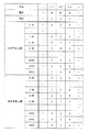
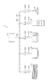
ホームコントローラ10のメモリ111では、家電群40のユーザについての、カレンダ情報が登録されている。図3は、カレンダ情報の内容の一例を模式的に示す図である。
<Calendar information>
In the
図3を参照して、カレンダ情報では、各日についての、在室予定人数と来客予定人数とが格納されている。在室予定人数とは、家電群40が設置される家屋に居住する家族のうち、当該家屋に存在する予定の者の数である。来客予定人数とは、家電群40が設置される家屋に居住する家族以外の者であって、当該家屋に存在する予定の者の数である。
Referring to FIG. 3, the calendar information stores the number of people scheduled to stay in the room and the number of people scheduled to visit for each day. The planned occupancy number is the number of persons who are scheduled to exist in the house among the families living in the house where the
カレンダ情報では、各日について、月日、曜日、祝日についての情報が格納され、また、1時間ごとの在室予定人数と来客予定人数が格納されている。たとえば、4月1日日曜日の午前8時から9時までの間(図3の「4/1」の「8:00」に対応)では、在室予定人数は4人であり、来客予定人数は2人である。 In the calendar information, for each day, information on the date, day of the week, and holidays is stored, and the number of people who are in the room and the number of visitors that are scheduled for each hour are stored. For example, between 8 am and 9 am on Sunday, April 1 (corresponding to “8:00” of “4/1” in FIG. 3), the number of people scheduled to be in the room is 4, and the number of visitors Are two people.
「祝日についての情報」とは、たとえば、各日が「国民の休日に関する法律」で定められた休日に該当するか否かの情報である。当該休日に該当すれば祝日の欄には「祝日」と標記される(図3では、該当する日は記載されていない)。一方、当該休日に該当しなければ祝日の欄には「−」と標記される。 “Information about holidays” is, for example, information on whether or not each day falls on a holiday defined by the “National Holiday Law”. If it falls on the holiday, it is marked as “holiday” in the holiday column (in FIG. 3, the day is not shown). On the other hand, if it does not correspond to the holiday, “-” is marked in the holiday column.
なお、カレンダ情報は、記憶媒体200またはネットワーク上の記憶装置に格納されていても良い。
Note that the calendar information may be stored in the
<閾値調整処理>
[メインルーチン]
図4は、CPU110によって実行される、デマンド制御のデマンド目標値(閾値)を調整するための処理のフローチャートである。
<Threshold adjustment processing>
[Main routine]
FIG. 4 is a flowchart of processing for adjusting a demand target value (threshold value) for demand control, which is executed by the
図4を参照して、CPU110は、まずステップS10で、基本的な閾値(以下、「基本閾値」という)を決定して、ステップS20へ処理を進める。
Referring to FIG. 4,
ステップS20では、CPU110は、ステップS10で決定した基本閾値を、公知の態様で変更して、処理を終了する。
In step S20,
ホームコントローラ10では、所定時間ごと(たとえば、1時間ごと)に、図4を参照して説明された閾値調整処理が実行され、デマンド目標値(閾値)が決定される。つまり、デマンド目標値は、所定時間ごとに更新される。
In the
[基本閾値の決定]
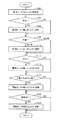
図5は、ステップS10の基本閾値決定処理のサブルーチンのフローチャートである。
[Determination of basic threshold]
FIG. 5 is a flowchart of the basic threshold value determination subroutine in step S10.
図5を参照して、CPU110は、まずステップS102において、閾値としてデフォルト値SV0を設定して、ステップS104へ処理を進める。なお、CPU110は、たとえばメモリ111に登録されているデフォルト値SV0を読込むことにより、記憶媒体200に格納されているデフォルト値SV0を読込むことにより、通信インターフェイス105を介してネットワーク上の記憶装置に格納されたデフォルト値SV0を読込むことにより、または、他の装置から通信インターフェイス105を介して入力されたデフォルト値SV0を取得することにより、ステップS102において閾値を設定する。
Referring to FIG. 5,
ステップS104では、CPU110は、本日が平日であるか否かを判断する。この判断は、カレンダ情報(図3)における、本日の曜日情報および祝日情報を参照することにより、実現される。具体的には、曜日情報が土曜日または日曜日である場合、または、祝日情報が「祝日」である場合には、本日は平日ではないと判断される。一方、それ以外の場合には、本日は平日であると判断される。本日が平日であると判断されれば、ステップS106へ処理が進められ、そうではないと判断されるとステップS108へ処理が進められる。
In step S104, the
ステップS106では、CPU110は、その時点で設定されている閾値を、特定の値V01を差し引くように更新して、ステップS108へ処理を進める。
In step S106, the
なお、本明細書では、閾値の調整について、値V01等の特定の値を、差し引いたり、加えたりすることによって、調整される。閾値が値を差し引かれるように更新されることは、デマンド制御における家電群40(負荷機器)における電力消費の上限を下げる方向に変更されることを意味する。また、閾値が値を加えるように更新されることは、デマンド制御における家電群40(負荷機器)における電力消費の上限を上げる方向に変更することに相当する。 In this specification, the threshold value is adjusted by subtracting or adding a specific value such as the value V01. Updating the threshold value to be deducted means that the threshold value is changed to lower the upper limit of power consumption in the household appliance group 40 (load device) in demand control. Moreover, updating the threshold value to add a value corresponds to changing the direction so as to increase the upper limit of power consumption in the household appliance group 40 (load device) in demand control.
ステップS108では、CPU110は、現在の季節を判断する。この判断は、たとえば、現在が3月から5月であれば、季節が「春」とされる。6月から8月であれば、季節は「夏」とされる。9月から11月であれば、季節は「秋」とされる。そして、12月から2月であれば、季節は「冬」とされる。そして、季節が夏または冬であると判断されると、ステップS110へ処理が進められる。一方、季節が春または秋であると、ステップS112へ処理が進められる。
In step S108, the
なお、季節を分ける期間を特定する情報は、たとえばメモリ111や記憶媒体200、もしくは、ネットワーク上の記憶装置に、格納されている。
Note that information for specifying a period for dividing a season is stored in, for example, the
ステップS110では、CPU110は、この時点で設定されている閾値を、特定の値V02差し引くように更新して、ステップS112へ処理を進める。
In step S110, the
ステップS112では、CPU110は、その時点で、家屋内に存在する予定の人数が0であるか、つまり、当該家屋において人が不在であるか否かが判断される。この判断は、カレンダ情報(図3)を参照することにより、実現される。
In step S112,
ステップS110の処理は、一定期間毎(たとえば、1時間毎)に実行される。そして、ステップS112では、CPU110は、その時点に対応するカレンダ情報での在室予定人数と来客予定人数の和が「0」であるか否かによって、実現される。
The process of step S110 is performed every fixed period (for example, every hour). Then, in step S112, the
たとえば、4月2日月曜日の午前9時から10時までの間(図3の「4/2」の「9:00」に対応)では、在室予定人数と来客予定人数がいずれも0人である。したがって、この場合には、ステップS112からステップS114へ処理が進められる。一方、上記したように、4月1日日曜日の午前8時から9時までの間は、在室予定人数が4人であり、来客予定人数が2人であるため、家屋には人が存在する予定とされている。この場合には、ステップS112からステップS116へ処理が進められる。 For example, between 9 am and 10 am on Monday, April 2 (corresponding to “9:00” of “4/2” in FIG. 3), the number of people in the room and the number of visitors are both 0 It is. Therefore, in this case, the process proceeds from step S112 to step S114. On the other hand, as mentioned above, between 8 am and 9 am on Sunday, April 1, there are 4 people in the room and 2 people in the room, so there are people in the house. It is supposed to be. In this case, the process proceeds from step S112 to step S116.
ステップS114では、CPU110は、その時点で登録されている閾値を、特定の値V03差し引くように更新して、ステップS116へ処理を進める。 In step S114, CPU110 updates the threshold value registered at that time so that specific value V03 may be deducted, and advances a process to step S116.
ステップS116では、CPU110は、家屋に存在する予定の人数が特定の人数を下回っているか否かが判断される。ここでの「特定の人数」とは、たとえば予めユーザによって、タッチセンサ102等を介して登録され、メモリ111等に格納されている。なお、「特定の人数」とは、当該家屋に居住している人の数であってもよい。
In step S116,
なお、ステップS116における、家屋に存在する予定の人数とは、カレンダ情報に登録されている、対応する時間帯の在室予定人数と来客予定人数の和である。 Note that the number of people scheduled to exist in the house in step S116 is the sum of the number of people in the room and the number of people scheduled to visit registered in the calendar information.
そして、CPU110は、存在予定の人数が特定の人数より下回ると判断するとステップS118へ処理を進め、特定の人数以上であると判断するとステップS120へ処理を進める。
If
ステップS118では、CPU110は、その時点で登録されている閾値を、特定の値V04差し引くように更新して、ステップS120へ処理を進める。
In step S118,
ステップS120では、CPU110は、現在、ホームコントローラ10の対象となっている家庭に来客がある予定であるか否かを判断し、そうであると判断するとステップS122へ処理を進める。一方、ないと判断するとそのまま図4へ処理をリターンさせる。
In step S120,
なお、ステップS120における判断は、カレンダ情報において、現在の時間帯に対応する来客予定人数が1以上であるか否かを判断することによって、実現される。 Note that the determination in step S120 is realized by determining whether or not the planned number of visitors corresponding to the current time zone is 1 or more in the calendar information.
以上、図5を参照して説明した基本閾値決定処理では、カレンダ情報に従って、閾値は、特定の値を差し引かれたり加えられて、更新された(ステップS106等)。 As described above, in the basic threshold value determination process described with reference to FIG. 5, the threshold value is updated by subtracting or adding a specific value according to the calendar information (step S106, etc.).
たとえば、ステップS112における現在の属する時間帯に家屋において人が不在である場合、または、ステップS116の当該時間帯の家屋に存在する人数が特定の人数を下回る場合には、閾値が値を差し引かれて更新される。これらの場合は、いずれも、家屋においてユーザが家電群40を利用する機会が少なくなることが予想され、これにより、当該家屋における家電群40による電力需要の低減が予測される。そして、このような場合には、閾値が、家電群における電力消費の上限が引き下げられる方向に、更新される。
For example, if there is no person in the house in the current time zone in step S112, or if the number of people in the house in the time zone in step S116 is less than a specific number of people, the threshold is deducted. Updated. In any of these cases, it is expected that there will be fewer opportunities for the user to use the
また、図5の処理では、ステップS104で本日が「平日」である場合や、現在の季節が夏または冬である場合に、閾値が特定の値を差し引かれるように更新された(ステップS104,S106、ステップS108,S110)。 Further, in the process of FIG. 5, when today is “weekday” in step S104, or when the current season is summer or winter, the threshold is updated so that a specific value is subtracted (step S104, S106, steps S108, S110).
平日であれば、当該家屋を含む電力会社の管内において、電力需要の増大が予測される。 On weekdays, an increase in power demand is predicted within the jurisdiction of the power company including the house.
また、季節が夏または冬であれば、冷房または暖房のため、春または秋と比較して、当該家屋を含む電力会社の管内において、電力需要の増大が予測される。そして、図5の処理では、このような場合に、閾値が特定の値を差し引かれるように更新される。 Further, if the season is summer or winter, an increase in electric power demand is predicted in the jurisdiction of the electric power company including the house for cooling or heating compared to spring or autumn. In the process of FIG. 5, in such a case, the threshold value is updated so that a specific value is subtracted.
また、図5の処理では、当該家屋において来客が予定されている時間帯には、閾値が特定の値を加えられるように更新される(ステップS120,122)。 In the process of FIG. 5, the threshold value is updated so that a specific value is added during a time zone in which the customer is scheduled in the house (steps S120 and 122).
このように、図5の処理では、家電群40のユーザにおいて特定の事情がある場合、家電群40による電力消費の上限を引き上げる方向に、閾値が変更される。これにより、ユーザは、来客がある時間帯では、空気調和機41を含む家電群40を、その時点での家屋の状況に合せて利用することができる。
As described above, in the process of FIG. 5, when there is a specific circumstance in the user of the
図4の処理が一定期間毎に実行されることにより、図5の処理も一定時間ごとに実行される。これにより、ホームコントローラ10によって取扱われる閾値は、一定時間毎に、デマンド制御に制御の閾値のデフォルト値SV0が読込まれ、当該デフォルト値SV0が、カレンダ情報に従って調整される。
By executing the process of FIG. 4 at regular intervals, the process of FIG. 5 is also executed at regular intervals. As a result, the threshold value handled by the
<閾値調整処理の変形例>
以上説明した本実施の形態では、図5を参照して説明されたように決定された基本閾値は、ステップS20において、公知の態様で変更が加えられる。
<Modification of threshold adjustment process>
In the present embodiment described above, the basic threshold value determined as described with reference to FIG. 5 is changed in a known manner in step S20.
なお、当該変更の処理として、温度情報が利用されてもよい。
図6は、温度情報に基づいて閾値を変更するための処理のフローチャートである。
Note that temperature information may be used as the change process.
FIG. 6 is a flowchart of processing for changing the threshold based on the temperature information.
図6を参照して、ステップSA202では、CPU110は、図5を参照して説明されたように決定された基本閾値を読込んで、ステップSA204へ処理を進める。
Referring to FIG. 6, in step SA202,
ステップSA204では、CPU110は、温度センサ51等から取得した温度情報が30℃以上であるか否かを判断し、そうであると判断するとステップSA206へ処理を進める。
In step SA204,
一方、30℃未満であると判断するとステップSA208へ処理を進める。
ステップSA206では、CPU110は、その時点での閾値を、特定の値V11を差し引くように更新して、図4へ処理をリターンさせる。
On the other hand, if it is determined that the temperature is less than 30 ° C., the process proceeds to step SA208.
In Step SA206, the
一方、ステップSA208では、CPU110は、温度情報によって特定される温度が10℃以下であるか否かを判断し、そうであると判断するとステップSA210へ処理を進めて、その時点で登録されている閾値を、特定の値V12を差し引くように更新して、図4へ処理をリターンさせる。一方、10℃を超えていると判断すると、そのまま図4へ処理をリターンさせる。
On the other hand, in step SA208,
以上説明された図6の処理では、現在の気温が30℃以上または10℃以下の場合には、閾値が特定の値を差し引くように更新される。これにより、家屋に電力を供給する電力会社の管内において、他の家屋においても電力需要が増大することが予測されるときには、当該家屋の家電群40による電力消費の上限を下げる方向に、閾値が変更される。
In the process of FIG. 6 described above, when the current temperature is 30 ° C. or higher or 10 ° C. or lower, the threshold is updated so as to subtract a specific value. Thereby, in the jurisdiction of the electric power company that supplies electric power to the house, when it is predicted that the electric power demand will increase also in other houses, the threshold value is set in the direction of lowering the upper limit of the electric power consumption by the
[時刻情報を利用した閾値の変更]
図7は、タイマ119等から取得した時刻情報を利用して閾値を変更するための処理のフローチャートである。
[Change of threshold value using time information]
FIG. 7 is a flowchart of processing for changing the threshold value using the time information acquired from the
図7を参照して、まずステップSB202では、CPU110は、その時点で登録されている閾値を読込んで、ステップSB204へ処理を進める。
Referring to FIG. 7, first in step SB202,
ステップSB204では、CPU110は、現時点の時刻が、夏の日中であるか、または、冬の朝もしくは晩であるか否かを判断する。「夏の日中」とは、たとえば、6月から8月の、午前11時から午後3時までの時間帯をいう。また、「冬の朝」とは、12月から2月までの午前6時から午前8時までの期間をいう。また、「冬の晩」とは、たとえば、12月から2月までの午後6時から午後9時までの期間をいう。そして、CPU110は、ステップSB204で、現在時刻の日付および時刻が、上記した夏の日中、または、冬の朝もしくは晩の期間に属するか否かを判断し、属すると判断するとステップSB206へ処理を進め、その時点での閾値を、特定の値V21差し引くように更新して、図4へ処理をリターンさせる。一方、属さないと判断すると、CPU110は、そのまま図4へ処理をリターンさせる。
In step SB204,
図7の処理によれば、夏の日中または冬の朝もしくは晩には、閾値が特定の値を差し引くように更新される。 According to the process of FIG. 7, the threshold value is updated so as to subtract a specific value during the summer day or in the winter morning or evening.
これらの期間は、空気調和機41による電力消費が、電力会社の管内において増大することが予測される。夏の日中は、空気調和機41による冷房が、また、冬の朝や晩は空気調和機41による暖房が、多く利用されることが予測されるからである。
During these periods, power consumption by the
そして、図7の処理では、電力会社の管内において電力需要の増大が予測される当該期間において、家屋の家電群による電力消費の上限を下げる方向で、閾値が更新される。 In the process of FIG. 7, the threshold value is updated in a direction of lowering the upper limit of power consumption by the home appliance group in the house during the period in which the increase in power demand is predicted within the jurisdiction of the power company.
[温度情報と時刻情報が組合された条件に基づく閾値の変更]
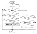
図8は、ホームコントローラ10において、閾値を、温度情報と時刻情報を組合せた条件に基づいて変更するための処理のフローチャートである。
[Change of threshold based on the condition that temperature information and time information are combined]
FIG. 8 is a flowchart of a process for changing the threshold value based on a combination of temperature information and time information in the
図8を参照して、CPU110では、その時点で設定されている閾値を読込んで、ステップSB204へ処理を進める。ステップSB204では、CPU110は、ステップS108(図5参照)と同様に、現在の季節を判定し、当該季節が夏であればステップSC206へ処理を進め、冬であればステップSC212へ処理を進め、春または秋であればそのまま図4へ処理をリターンさせる。
Referring to FIG. 8,
ステップSC206では、CPU110は、現在の時刻が、日中のピーク時として設定されている時間帯に属するか否かを判断する。このような設定のための情報が、たとえば、メモリ111等において、登録されている。そして、CPU110は、日中のピーク時に属すると判断するとステップSC208へ処理を進め、そうではないと判断するとそのまま図4へ処理をリターンさせる。
In step SC206,
ステップSC208では、CPU110は、現在の温度が30℃以上であるか否かを判断し、そうであると判断するとステップSC210へ処理を進め、そうではない(つまり、温度が30℃未満である)と判断すると、そのまま図4へ処理をリターンさせる。
In step SC208,
ステップSC210では、CPU110は、ステップSC202で読込んだ閾値を、特定の値V31差し引くように更新して、図4へ処理をリターンさせる。
In step SC210,
一方、ステップSC212では、CPU110は、現在の時刻が、朝または夕方のピーク時として特定される時間帯に属するか否かを判断する。これらの時間帯を特定する情報は、たとえばメモリ111に格納されている。そして、CPU110は、朝または夕方のピーク時に属すると判断するとステップSC214へ処理を進め、現在時刻がそれ以外の時間帯に属すると判断するとそのまま図4へ処理をリターンさせる。
On the other hand, in step SC212,
ステップSC214では、CPU110は、現在の温度が10℃以下であるか否かを判断し、そうであると判断するとステップSC216へ処理を進め、現在の温度が10℃を超えていると判断するとそのまま図4へ処理をリターンさせる。
In step SC214,
ステップSC216では、CPU110は、ステップSC202で読込な主張を、特定の値V32差し引くように更新して、図4へ処理をリターンさせる。
In step SC216,
図8の処理では、夏の電力消費のピーク時であって気温が30℃以上の場合、もしくは、冬の電力需要が多くなる時間帯(朝または夕方)であって気温が10℃以下の場合には、閾値が、家屋の家電群40による電力消費の上限を低下させる方向に、変更される。これにより、家屋に電力を供給する電力会社の管内において電力需要が増大する場合、家屋における家電群40による電力消費の上限が抑えられるように、閾値が変更される。
In the process of FIG. 8, when the temperature is at a peak of summer power consumption and the temperature is 30 ° C. or higher, or when the power demand in winter is high (morning or evening) and the temperature is 10 ° C. or lower. In this case, the threshold value is changed so as to reduce the upper limit of power consumption by the
[湿度に基づく閾値の変更]
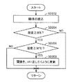
図9は、ホームコントローラ10において、湿度情報に基づいて閾値を変更するための処理のフローチャートである。
[Change of humidity based threshold]
FIG. 9 is a flowchart of a process for changing the threshold value based on the humidity information in the
図9を参照して、CPU110は、まずステップSD202で現在設定されている閾値を読込んで、ステップSD204へ処理を進める。
Referring to FIG. 9,
ステップSD204では、CPU110は、現在の湿度が80%以上であるか否かを判断し、そうであると判断するとステップSD206へ処理を進め、80%未満であると判断するとそのまま図4へ処理をリターンさせる。
In step SD204, the
ステップSD206では、CPU110は、現在の温度が30℃以上であるか否かを判断し、そうであると判断するとステップSD208へ処理を進め、30℃未満であると判断するとそのまま図4へ処理をリターンさせる。
In step SD206,
ステップSD208では、CPU110は、現在設定されている閾値を、特定の値V41差し引くように更新して、図4へ処理をリターンさせる。
In step SD208, the
図9の処理では、湿度が高くまた温度が高い場合、つまり、家屋に電力を供給する電力会社の管内において他の世帯においても空気調和機41による冷房や除湿運転のために電力需要の増大が予測される場合には、家電群40による電力消費の上限を下げる方向に、閾値が変更される。
In the process of FIG. 9, when the humidity is high and the temperature is high, that is, the demand for electric power increases due to cooling and dehumidifying operation by the
[日射量情報に基づく閾値の変更]
図10は、ホームコントローラ10において、日射量情報に基づいて閾値を変更するための処理のフローチャートである。
[Change threshold based on solar radiation information]
FIG. 10 is a flowchart of processing for changing the threshold value based on the solar radiation amount information in the
図10を参照して、CPU110は、まずステップSE202において、現在設定されている閾値を読込んで、ステップSE204へ処理を進める。
Referring to FIG. 10,
ステップSE204では、CPU110は、ステップS108(図5参照)と同様に現在の季節を判定し、夏であればステップSE206へ処理を進め、冬であればSE210へ処理を進め、春または秋であればそのまま図4へ処理をリターンさせる。
In step SE204, the
ステップSE206では、CPU110は、日射量が3MJ(メガジュール)/m2以上であるか否かを判断し、そうであると判断するとステップSE208へ処理を進め、日射量が3MJ/m2未満であると判断するとそのまま図4へ処理をリターンさせる。
In step SE206,
ステップSE208では、CPU110は、ステップSE202で読込んだ閾値を、特定の値V51差し引くように更新して、図4へ処理をリターンさせる。
In step SE208, the
ステップSE210では、CPU110は、現在の時刻が昼間の時間帯に属するか否かを判断する。昼間の時間帯とは、たとえば、午前10時から午後3時である。昼間の時間帯を特定する情報は、たとえば、メモリ111に登録されている。
In step SE210,
そして、昼間の時間帯であると判断するとステップSE212へ処理を進め、それ以外の時間帯に属すると判断するとそのまま図4へ処理をリターンさせる。 If it is determined that it is a daytime time zone, the process proceeds to step SE212, and if it is determined that it belongs to another time zone, the process is returned to FIG. 4 as it is.
ステップSE212では、CPU110は、現在の日射量が1MJ/m2以下であるか否かを判断し、そうであると判断するとステップSE214へ処理を進め、1MJ/m2を超えていると判断するとそのまま図4へ処理をリターンさせる。
In step SE212,
ステップSE214では、CPU110は、ステップSE202で読込んだ閾値を、特定の値V52差し引くように更新して、図4へ処理をリターンさせる。
In step SE214,
図10の処理では、電力会社の管内において電力需要の増大が予測される場合、つまり、夏の日差しが強いとき、または冬であって日差しが弱い場合には、家電群40による電力消費の上限を下げる方向に、閾値が変更される。
In the process of FIG. 10, when an increase in power demand is predicted within the jurisdiction of the power company, that is, when the sunlight in summer is strong, or when the sunlight is weak in winter, the upper limit of power consumption by the
<その他の変形例等>
図6〜図10のそれぞれを参照して説明された処理は、単独で実行されても良いし、組み合わされて実行されても良い。この場合、「組み合わされて実行」とは、図6〜図10の中の1の処理が実行された後に、他の処理が実行されることを言う。
<Other variations, etc.>
The processing described with reference to each of FIGS. 6 to 10 may be executed alone or in combination. In this case, “combined and executed” means that after one of the processes in FIGS. 6 to 10 is executed, another process is executed.
たとえば、図6の処理が実行された後、図7の処理が実行されても良い。この場合、図7のステップSB202において読み込まれる閾値は、図6のステップS206またはステップS210における更新後の閾値である。ただし、図6の処理において、ステップS206またはステップS210のいずれにおいても閾値が更新されなかった場合には、ステップSB202で読み込まれる閾値は、ステップSA202で読み込まれたそのままの閾値である。 For example, the process of FIG. 7 may be executed after the process of FIG. 6 is executed. In this case, the threshold value read in step SB202 in FIG. 7 is the updated threshold value in step S206 or step S210 in FIG. However, in the process of FIG. 6, when the threshold value is not updated in either step S206 or step S210, the threshold value read in step SB202 is the same threshold value read in step SA202.
また、組み合わされて実行される処理の数は「2」に限定されない。
また、本実施の形態では、電力会社の電力供給管内に含まれる複数の家庭(家屋)のうち1の家庭に設置されるホームコントローラ10が、電力管理装置の一実施の形態として例示された。このような場合、たとえば、電力会社は、当該ホームコントローラ10を設置した家庭に対して料金における一定のインセンティブを与えるなどのビジネスモデルが考えられる。
Further, the number of processes executed in combination is not limited to “2”.
Further, in the present embodiment, the
<システム構成の変形例>
図1に示された制御システム1では、ホームコントローラ10は、家電群40の各家電と直接通信し、当該各家電のエネルギー消費を管理している。
<Modification of system configuration>
In the
ここで、ホームコントローラ10は、測定器等の所定の通信用器具を介して家電群40の各家電と通信することにより、当該各家電のエネルギー消費を管理しても良い。このようなシステム構成の変形例を、以下に説明する。
Here, the
[測定器を用いた変形例]
図11は、制御システム1の、測定器を用いた変形例の全体構成を示す模式図である。
[Modification using measuring instrument]
FIG. 11 is a schematic diagram illustrating an overall configuration of a modified example of the
図11を参照して、本実施の形態に従う制御システム1は、住宅やオフィスなどの家屋内に設置される。より具体的には、制御システム1は、電力を消費する電気機器として、複数の家電機器を含む。
Referring to FIG. 11,
図11には、これらに限られるものではないが、家電機器として、家屋内に設置される空気調和機41、テレビ42、電子レンジ44、冷蔵庫45、および照明43(これらを「家電群40」とも総称する。)などが図示されている。また、制御システム1は、電力を発生する電気機器としての太陽光発電装置、および電力の蓄電/放電を行なう蓄電池を含む場合も有り得る。蓄電池200Yは、住宅などに設置されるものであってもよいし、自動車用の蓄電池を住宅用の蓄電池として兼用するものであってもよい。
In FIG. 11, although not limited to these, as home appliances, an
さらに、制御システム1は、家電群40の各家電に関連付けられた測定器400A〜400Eを含む。ホームコントローラ10は、有線または無線のネットワーク401を介して、家電群40の各家電に関連付けられた測定器400A〜400Eや、太陽光発電装置、蓄電池、パワーコンディショナなどとの間でデータ通信が可能である。
Furthermore, the
ネットワーク401としては、任意のものを利用することができるが、有線のネットワークであれば、例えば、イーサネット(登録商標)、PLC(Power Line Communications)などを用いることができる。また、無線のネットワークであれば、例えば、IEEE802.11規格に準拠する無線LAN(Local Area Network)、ZigBee(登録商標)、Bluetooth(登録商標)、赤外線通信方式などを用いることができる。さらに、複数の通信方式を組み合わせてもよい。
An arbitrary network can be used as the
測定器400は、家電群40のいずれかの家電に関連付けられ、当該関連付けられた家電群40における電力消費に関する情報を測定するとともに、その測定情報をホームコントローラ10へ送信する。典型的には、測定器400としては、電力線402と家電群40のプラグとの間に配置されて電力消費の状態を測定する消費電力測定装置が用いられる。
The measuring
図11に示す例では、電力線402に5つの測定器400A〜400Eが電気的に接続されている。測定器400Aには、空気調和機41のプラグ250Aが接続されており、測定器400Bには、テレビ42のプラグ250Bが接続されており、測定器400Cには、電子レンジ44のプラグ250Cが接続されており、測定器400Dには、冷蔵庫45のプラグ250Dが接続されており、測定器400Eには、照明43のプラグ250Eが接続されている。そのため、測定器400A〜400Eは、それぞれ、空気調和機41、テレビ42、電子レンジ44、冷蔵庫45、照明43における電力消費に関する電力情報を測定する。
In the example shown in FIG. 11, five
ホームコントローラ10は、各家電群40に関連付けられた測定器400からそれぞれ送信される電力消費に関する測定情報をメモリ111(図2参照)に格納する。
The
ホームコントローラ10は、制御システム1における電力消費/発生の状態などをユーザに提示したり、ユーザから制御システム1における電力管理に関する指示を受け付けたりするような、ユーザインターフェイスを提供する。
The
また、ホームコントローラ10は、メモリ111に格納される電力消費に関する測定情報などに基づいて、電力消費に関するグラフ等を表示することも可能である。ホームコントローラ10は、ポータブル型であってもよいし、テーブル上に配置されたベースに対して着脱自在であってもよいし、部屋の壁などに固定されるものであってもよい。
The
本例においては、ホームコントローラ10が、各測定器とデータ通信してデータを取得する構成について主に説明したが、図示しないデータを収集するサーバを設けて、当該サーバが各測定器とデータ通信してデータを蓄積し、ホームコントローラ10が当該サーバに蓄積されたデータを取得する形態の構成とすることも可能である。
In the present example, the configuration in which the
<測定器400>
図12は、図11の制御システムの測定器400の外観図である。ここで、図12(A)には、測定器400のソケット4001を含む斜視図を示し、図12(B)には、測定器400の側面図を示し、図12(C)には、測定器400のプラグ4002を含む斜視図を示す。
<
FIG. 12 is an external view of the measuring
図12(A)〜図12(C)を参照して、測定器400は、電力線402を流れる電力を供給するためのソケットと家電群40のプラグとの間に介挿されるように配置される。より具体的には、図12(A)を参照して、測定器400の表面4051には、プラグ差込用のソケット4001が設けられている。一方、図12(B)および図12(C)を参照して、測定器400の表面4051とは反対側の面である表面4053には、プラグ4002が設けられている。ソケット4001には、家電群40のプラグが差し込まれるとともに、プラグ4002は、家屋内に設けられる電力線402を介して電力を供給するためのソケット(コンセント/アウトレット)に差し込まれる。
With reference to FIG. 12 (A)-FIG. 12 (C), the measuring
なお、測定器400は、なるべく薄い方が好ましいので、側面4052の厚さは可能な限り小さく設計される。
Since the measuring
測定器400の表面4051には、さらに、LED(Light Emitting Diode)4041および設定ボタン4042が設けられている。LED4041は、測定器400におけるデータ処理状態を表示する。より具体的には、LED4041は、データ処理状態に応じて、点灯の有無、点滅の有無/周期、発光色などを異ならせる。設定ボタン4042は、ユーザ操作を受け付けるための入力手段であり、ユーザによって操作されると、測定器400における初期設定などが開始される。
On the
図13は、本変形例の測定器400のハードウェア構成を示す模式図である。
図13を参照して、測定器400は、ソケット4001、プラグ4002、LED4041、および設定ボタン4042に加えて、ソケット4001とプラグ4002とを電気的に接続する一対の主配線4004および4005と、主配線4005に挿入されたシャント抵抗4003と、電源部4007と、電力検出部4010と、通信モジュール4020と、アンテナ4030とを含む。
FIG. 13 is a schematic diagram illustrating a hardware configuration of the measuring
Referring to FIG. 13, measuring
電力検出部4010は、プラグ4002からソケット4001へ流れる電力を検出する。より具体的には、電力検出部4010は、電圧入力ADC(Analog to Digital Converter:アナログ・デジタル変換器)4011と、電流入力ADC4012と、乗算器4013と、デジタル/周波数変換部4014とを含む。
The
電圧入力ADC4011は、配線V1PおよびV1Nを介して、主配線4004および4005にそれぞれ接続される。電圧入力ADC4011は、主配線間に生じる電圧(電位差)を示すデジタル信号を乗算器4013へ出力する。
電流入力ADC4012は、配線V2PおよびV2Nを介して、主配線4005に挿入されたシャント抵抗4003の両端と電気的に接続される。シャント抵抗4003は、流れる電流値を測定するために使われる微小な(数百マイクロΩ)抵抗である。電流入力ADC4012は、シャント抵抗4003に流れる電流の電流値を示すデジタル信号を乗算器4013へ出力する。
The
乗算器4013は、電圧入力ADC4011からのデジタル信号(電圧値)と、電流入力ADC4012からのデジタル信号(電流値)とを乗算し、その結果得られた値(消費電力/単位:WまたはkW)を示すデジタル信号をデジタル/周波数変換部4014へ出力する。
The
デジタル/周波数変換部4014は、乗算器4013からのデジタル信号を周波数信号に変換し、その結果得られた周波数信号を通信モジュール4020へ出力する。
The digital /
電源部4007は、測定器400の各コンポーネントに電力を供給する。電源部4007は、主配線4004および4005に接続され、プラグ4002からソケット4001へ流れる電力の一部を測定器400の動作用の電力として利用する。電源部4007は、交流電力を直流電力に変換した後、その直流電力を電力検出部4010および通信モジュール4020へ供給する。
The
通信モジュール4020は、電力検出部4010により算出されたソケット4001に接続されている電気機器における消費電力を示す無線信号を、アンテナ4030を介して送出する。より具体的には、通信モジュール4020は、CPU4021と、ROM4022と、RAM4023と、GPIO(General Purpose Input/Output)4024と、無線RF(Radio Frequency)部4025とを含む。
The
GPIO4024は、デジタル/周波数変換部4014から入力された周波数信号を受信し、その周波数信号の情報をCPU4021へ出力する。
The
CPU4021は、GPIO4024からの周波数信号の情報を所定のロジックに従ってデータ変換し、その結果を無線RF部4025へ出力する。無線RF部4025は、CPU4021からのデータ変換結果に基づいて搬送波を変調することで、無線信号を生成する。無線RF部4025で生成された無線信号は、アンテナ4030を介して、送信される。
The
CPU4021は、ROM4022に予め格納されているプログラムを実行することで、上述のような処理を実現する。RAM4023は、CPU4021によるプログラムの実行に必要なワークデータを格納する。
The
<測定情報>
測定器400は、基本的には接続されている電気機器で消費される消費電力(単位:WまたはkW))を測定する。この消費電力を所定時間に亘って積算することで、当該電気機器の消費電力量(単位:WhまたはkWh)が算出される。
<Measurement information>
The measuring
ホームコントローラ10は、それぞれの電気機器における消費電力および消費電力量のいずれをも表示することが可能である。さらに、複数の電気機器をグルーピング化して、そのグループ全体についての消費電力および消費電力量を表示する。
The
そのため、測定器400から送信される対応する家電群40についての測定情報の実装例としては、例えば、以下のようになる(但し、以下の例に限られるものではない)。
Therefore, an example of mounting measurement information about the corresponding
(1) 測定器400が家電群40における消費電力を所定周期ごと(例えば、1秒ごと)に測定し、当該測定周期と同じ送信周期で、その測定された消費電力を測定情報として送信する。
(1) The
(2) 測定器400が家電群40における消費電力を所定周期ごと(例えば、1秒ごと)に測定し、当該測定周期よりは長い送信周期で、前回の送信から今回の送信までの間に測定された複数の消費電力を測定情報として送信する。
(2) The
(3) 測定器400が家電群40における消費電力を所定周期ごと(例えば、1秒ごと)に測定し、当該測定周期よりは長い送信周期で、前回の送信から今回の送信までの間に測定された複数の消費電力を平均して得られた平均消費電力を測定情報として送信する。
(3) The
(4) (2)または(3)において、前回の送信から今回の送信までの間に測定された複数の消費電力を積算した消費電力量を測定情報に付加した上で送信する。さらに、複数の消費電力の平均値・最小値・最大値などを付加してもよい。 (4) In (2) or (3), transmission is performed after adding to the measurement information a power consumption amount obtained by integrating a plurality of power consumptions measured from the previous transmission to the current transmission. Furthermore, you may add the average value, minimum value, maximum value, etc. of some power consumption.
測定情報には、測定器400が何らかの手段で取得した時刻情報を付加してもよいが、一般的には、ホームコントローラ10が測定情報を受信すると、そのときの時刻を時計112より取得し、受信した測定情報と関連付けてメモリ111に格納する。
Although time information acquired by the measuring
ホームコントローラ10と測定器400との間での測定情報の遣り取りについては、任意のプロトコルを採用することができる。典型的には、測定器400が自身の測定した測定結果を含むパケットをブロードキャストし、ホームコントローラ10がこのパケットを受信する構成が採用される。但し、ホームコントローラ10がそれぞれの測定器400に対して定期的にポーリングするようにしてもよい。
An arbitrary protocol can be adopted for exchanging measurement information between the
[中継機を用いた変形例]
本変形例の制御システムでは、システムの構成は、図1に示されたものから図14に示されたものへと変更される。図14の制御システム1では、家電群の各家電のデータは、中継器1001に一旦集められる。そして、中継器1001に集められたデータが、必要に応じてホームコントローラ10へと送信される。
[Modified example using a repeater]
In the control system of this modification, the configuration of the system is changed from that shown in FIG. 1 to that shown in FIG. In the
また、本変形例の制御システムでは、ホームコントローラ10から各家電に送信されるデータも、中継器1001に一旦集められる。中継器1001は、ホームコントローラ10から受信した各家電に対する制御データ等のデータを、各家電へと送信する。
In the control system of this modification, data transmitted from the
なお、図14の制御システム1では、各家電は、図11〜図13を参照して説明したような測定器400A等を介して中継器1001と通信するように記載されているが、通信機能が設けられている家電については、中継器1001と直接通信する場合もあり得る。つまり、図14に示された測定器400A,400B,400Eのいずれかもしくはすべては省略される場合もあり得る。
In the
また、図14では図示を省略しているが、本変形例においてもホームコントローラ10は、図2に示した電力センサ50、温度センサ51、湿度センサ52、および日射センサ53の各センサから適宜データを取得する。そして、本変形例では、各センサのデータも、中継器1001に格納され、ホームコントローラ10は、中継器1001に格納された各センサのデータを取得する場合もあり得る。
Although not shown in FIG. 14, in this modification as well, the
図15は、中継器1001のブロック図である。図15を参照して、中継器1001は、制御部1101と、操作部1102と、表示部1103と、高速通信インターフェイス部1104と、電源部1105と、無線RF(Radio Frequency)内蔵通信コントローラ部1106と、アンテナ1107と、設定ボタン1108とを備える。
FIG. 15 is a block diagram of the
無線RF内蔵通信コントローラ部1106は、CPU(Central Processing Unit)1161と、ROM(Read Only Memory)1162と、RAMRandom Access Memory)1163と、GPIO(General Purpose Input/Output)1164と、無線RF部1165と、UART(Universal Asynchronous Receiver Transmitter)1166とを含む。なお、無線RF内蔵通信コントローラ部1106が、ZigBee(登録商標)コーディネータ部に該当する。また、ROM1162と、RAM1163と、UART1166と、GPIO1164と、無線RF部1165とは、それぞれ、CPU1161に接続されている。
A wireless RF built-in
無線RF内蔵通信コントローラ部1106は、アンテナ1107と接続されている。無線RF内蔵通信コントローラ部1106は、ネットワーク上に存在する通信機器(ホームコントローラ10、測定器400A、等)との間の通信を制御する。
The wireless RF built-in
制御部1101のOS(Operating System)は、たとえばLinux(登録商標)を用いることができる。制御部1101は、CPU1161に比べて高性能なCPUを備えており、またメモリも豊富である。当該構成によって、中継器1001は、高度な情報処理を実現できる。
As the OS (Operating System) of the
操作部1102は、スイッチおよびタッチパネル等の入力デバイスである。表示部1103は、画像を表示するためのディスプレイ(たとえば、液晶ディスプレイ)である。
The
高速通信インターフェイス部1104は、外部のネットワークに接続されるブロードバンドルータ(図示略)との間でEthernet(登録商標)またはWiFi(登録商標)を用いた通信を行なうためのインターフェイスである。電源部1105は、制御部1101と無線RF内蔵通信コントローラ部1106とに電力を供給する。
The high-speed
制御部1101は、操作部1102、表示部1103と、高速通信インターフェイス部1104と、電源部1105と、無線RF内蔵通信コントローラ部1106とに接続されている。制御部1101は、中継器1001の全体的な動作を制御する。制御部1101は、操作部1102からの入力を受け付ける。また、制御部1101は、表示部1103に出力指示を出す。
The
今回開示された実施の形態およびその変形例はすべての点で例示であって制限的なものではないと考えられるべきである。本発明の範囲は上記した説明ではなくて特許請求の範囲によって示され、特許請求の範囲と均等の意味および範囲内でのすべての変更が含まれることが意図される。実施の形態およびその変形例において開示された技術は、可能な限り単独でも組み合わせても実施され得ることが意図される。 It should be thought that embodiment disclosed this time and its modification are illustrations in all the points, and are not restrictive. The scope of the present invention is defined by the terms of the claims, rather than the description above, and is intended to include any modifications within the scope and meaning equivalent to the terms of the claims. It is intended that the techniques disclosed in the embodiments and the modifications thereof can be implemented alone or in combination as much as possible.
1 制御システム、10 ホームコントローラ、40 家電群、41 空気調和機、42 テレビ、43 照明、50 電力センサ、51 温度センサ、52 湿度センサ、53 日射センサ、101 ディスプレイ、102 タッチセンサ、103 タッチパネル、104 入力部、105 通信インターフェイス、107 マイク、108 スピーカ、109 メモリインターフェイス、111 メモリ、112 RAM、119 タイマ、200 記憶媒体。
DESCRIPTION OF
Claims (10)
前記負荷機器による電力消費量のデマンド目標値を取得するための目標値取得手段と、
カレンダ情報を格納するための記憶手段と、
前記カレンダ情報に基づいて前記デマンド目標値を調整して設定するための設定手段とを備える、電力管理装置。 A power management device for executing demand control for power consumption by a load device,
Target value acquisition means for acquiring a demand target value of power consumption by the load device;
Storage means for storing calendar information;
A power management apparatus comprising: setting means for adjusting and setting the demand target value based on the calendar information.
前記設定手段は、さらに温度情報に基づいて、前記デマンド目標値を変更する、請求項1〜請求項4のいずれか1項に記載の電力管理装置。 A temperature information acquisition means for acquiring temperature information;
The power management device according to claim 1, wherein the setting unit further changes the demand target value based on temperature information.
前記設定手段は、さらに時刻情報に基づいて、前記デマンド目標値を変更する、請求項1〜請求項5のいずれか1項に記載の電力管理装置。 It further comprises time information acquisition means for acquiring time information,
The power management device according to any one of claims 1 to 5, wherein the setting unit further changes the demand target value based on time information.
前記設定手段は、さらに湿度情報に基づいて、前記デマンド目標値を変更する、請求項1〜請求項6のいずれか1項に記載の電力管理装置。 It further comprises humidity information acquisition means for acquiring humidity information,
The power management apparatus according to any one of claims 1 to 6, wherein the setting unit further changes the demand target value based on humidity information.
温度情報を取得するための温度情報取得手段とをさらに備え、
前記設定手段は、温度情報と時刻情報とを組み合わされた条件に基づいて、前記デマンド目標値を変更する、請求項1〜請求項5のいずれか1項に記載の電力管理装置。 Time information acquisition means for acquiring time information;
Temperature information acquisition means for acquiring temperature information,
The power management device according to any one of claims 1 to 5, wherein the setting unit changes the demand target value based on a condition in which temperature information and time information are combined.
前記設定手段は、さらに日射量情報に基づいて、前記デマンド目標値を変更する、請求項1〜請求項8のいずれか1項に記載の電力管理装置。 Further comprising solar radiation information acquisition means for acquiring solar radiation information,
The power management apparatus according to any one of claims 1 to 8, wherein the setting unit further changes the demand target value based on solar radiation amount information.
前記電力管理用プログラムは、前記コンピュータに、
前記負荷機器による電力消費量のデマンド目標値を取得するステップと、
カレンダ情報とを格納するステップと、
前記カレンダ情報に基づいて前記デマンド目標値を調整して設定するステップを実行させる、電力管理用プログラム。 A power management program executed by a computer of a power management apparatus for executing demand control for power consumption by a load device,
The power management program is stored in the computer.
Obtaining a demand target value of power consumption by the load device;
Storing calendar information; and
A power management program for executing a step of adjusting and setting the demand target value based on the calendar information.
Priority Applications (1)
| Application Number | Priority Date | Filing Date | Title |
|---|---|---|---|
| JP2012125880A JP2013252007A (en) | 2012-06-01 | 2012-06-01 | Power management device and program for power management |
Applications Claiming Priority (1)
| Application Number | Priority Date | Filing Date | Title |
|---|---|---|---|
| JP2012125880A JP2013252007A (en) | 2012-06-01 | 2012-06-01 | Power management device and program for power management |
Publications (1)
| Publication Number | Publication Date |
|---|---|
| JP2013252007A true JP2013252007A (en) | 2013-12-12 |
Family
ID=49850189
Family Applications (1)
| Application Number | Title | Priority Date | Filing Date |
|---|---|---|---|
| JP2012125880A Pending JP2013252007A (en) | 2012-06-01 | 2012-06-01 | Power management device and program for power management |
Country Status (1)
| Country | Link |
|---|---|
| JP (1) | JP2013252007A (en) |
Cited By (4)
| Publication number | Priority date | Publication date | Assignee | Title |
|---|---|---|---|---|
| CN104534620A (en) * | 2014-12-11 | 2015-04-22 | 广东美的制冷设备有限公司 | Air conditioner with Bluetooth module as well as Bluetooth module power-saving device and method thereof |
| WO2015128907A1 (en) * | 2014-02-27 | 2015-09-03 | パナソニック インテレクチュアル プロパティ コーポレーション オブ アメリカ | Control method, information provision method and program |
| JP2020141525A (en) * | 2019-02-28 | 2020-09-03 | パナソニックIpマネジメント株式会社 | Demand monitoring system, monitoring method and program |
| DE102022203455A1 (en) | 2022-04-06 | 2023-10-12 | Bob Patent Gmbh | Optimized load management for a heat pump |
Citations (8)
| Publication number | Priority date | Publication date | Assignee | Title |
|---|---|---|---|---|
| JP2001054176A (en) * | 1999-08-06 | 2001-02-23 | Sanyo Electric Co Ltd | Power control system for home electric appliance |
| JP2001339877A (en) * | 2000-05-29 | 2001-12-07 | Biiwan Factory:Kk | Power controller |
| JP2002044883A (en) * | 2000-07-24 | 2002-02-08 | Funai Electric Co Ltd | Advice system to save power |
| JP2006174582A (en) * | 2004-12-15 | 2006-06-29 | Matsushita Electric Ind Co Ltd | Demand-monitoring device |
| JP2009232517A (en) * | 2008-03-19 | 2009-10-08 | Panasonic Electric Works Co Ltd | Demand control system |
| JP2010075015A (en) * | 2008-09-22 | 2010-04-02 | Mitsubishi Electric Corp | Demand control system for household electric appliance |
| JP2011087420A (en) * | 2009-10-16 | 2011-04-28 | Panasonic Corp | Target electric-energy control system |
| JP2011247435A (en) * | 2010-05-21 | 2011-12-08 | Panasonic Electric Works Co Ltd | Air conditioning system |
-
2012
- 2012-06-01 JP JP2012125880A patent/JP2013252007A/en active Pending
Patent Citations (8)
| Publication number | Priority date | Publication date | Assignee | Title |
|---|---|---|---|---|
| JP2001054176A (en) * | 1999-08-06 | 2001-02-23 | Sanyo Electric Co Ltd | Power control system for home electric appliance |
| JP2001339877A (en) * | 2000-05-29 | 2001-12-07 | Biiwan Factory:Kk | Power controller |
| JP2002044883A (en) * | 2000-07-24 | 2002-02-08 | Funai Electric Co Ltd | Advice system to save power |
| JP2006174582A (en) * | 2004-12-15 | 2006-06-29 | Matsushita Electric Ind Co Ltd | Demand-monitoring device |
| JP2009232517A (en) * | 2008-03-19 | 2009-10-08 | Panasonic Electric Works Co Ltd | Demand control system |
| JP2010075015A (en) * | 2008-09-22 | 2010-04-02 | Mitsubishi Electric Corp | Demand control system for household electric appliance |
| JP2011087420A (en) * | 2009-10-16 | 2011-04-28 | Panasonic Corp | Target electric-energy control system |
| JP2011247435A (en) * | 2010-05-21 | 2011-12-08 | Panasonic Electric Works Co Ltd | Air conditioning system |
Cited By (5)
| Publication number | Priority date | Publication date | Assignee | Title |
|---|---|---|---|---|
| WO2015128907A1 (en) * | 2014-02-27 | 2015-09-03 | パナソニック インテレクチュアル プロパティ コーポレーション オブ アメリカ | Control method, information provision method and program |
| CN104534620A (en) * | 2014-12-11 | 2015-04-22 | 广东美的制冷设备有限公司 | Air conditioner with Bluetooth module as well as Bluetooth module power-saving device and method thereof |
| JP2020141525A (en) * | 2019-02-28 | 2020-09-03 | パナソニックIpマネジメント株式会社 | Demand monitoring system, monitoring method and program |
| JP7126206B2 (en) | 2019-02-28 | 2022-08-26 | パナソニックIpマネジメント株式会社 | DEMAND MONITORING SYSTEM, MONITORING METHOD AND PROGRAM |
| DE102022203455A1 (en) | 2022-04-06 | 2023-10-12 | Bob Patent Gmbh | Optimized load management for a heat pump |
Similar Documents
| Publication | Publication Date | Title |
|---|---|---|
| US9513340B2 (en) | Power information display device, power information display system and power information display method | |
| US10557876B2 (en) | System and method for home energy monitor and control | |
| Han et al. | More efficient home energy management system based on ZigBee communication and infrared remote controls | |
| JP5786097B2 (en) | Energy management system | |
| US9494625B2 (en) | Power management device, method of controlling power management device, and program for controlling power management device | |
| EP2501018A1 (en) | Power controller for electric devices, and telephone | |
| EP2849304B1 (en) | Electrical equipment and electric power control system | |
| JP5507527B2 (en) | Power management apparatus, control method for power management apparatus, and control program | |
| WO2014038368A1 (en) | Display device, administration device, display method, and program | |
| TW201346515A (en) | Smart energy-saving control method and system | |
| WO2016013843A2 (en) | Multi-function smart-grid unit for saving energy and method for operating same | |
| JP2013252007A (en) | Power management device and program for power management | |
| WO2016013842A1 (en) | Multi-tab power strip for preventing waste of standby power, and method for cutting off standby power using same | |
| JP6826441B2 (en) | Power consumption monitoring device | |
| KR20130100850A (en) | Smart meter for smart grid and method for performing service | |
| US9880579B2 (en) | Controller, method for controlling electrical device, device control system, and program | |
| JP5925577B2 (en) | Controller, controller control method, program | |
| JP5951362B2 (en) | Power management system and control method for power management apparatus | |
| US11646584B2 (en) | Energy allocation system | |
| Tsai et al. | Intelligent DC power monitoring system and sensor network based on ZigBee-equipped smart sockets | |
| KR20180016015A (en) | Control device of home energy management system and control system including same | |
| JP2017191521A (en) | Display method, program, and display system | |
| JP2013211718A (en) | Energy management device, control method for energy management device, control program, and energy management system | |
| Choi et al. | Energy Saving System for Home Energy Measurement and Efficient Power Control | |
| Ng et al. | Framework for Phantom Load Management |
Legal Events
| Date | Code | Title | Description |
|---|---|---|---|
| A621 | Written request for application examination |
Free format text: JAPANESE INTERMEDIATE CODE: A621 Effective date: 20150318 |
|
| A977 | Report on retrieval |
Free format text: JAPANESE INTERMEDIATE CODE: A971007 Effective date: 20160114 |
|
| A131 | Notification of reasons for refusal |
Free format text: JAPANESE INTERMEDIATE CODE: A131 Effective date: 20160209 |
|
| A02 | Decision of refusal |
Free format text: JAPANESE INTERMEDIATE CODE: A02 Effective date: 20160830 |