WO2014024641A1 - 薄板ガラスの製造方法 - Google Patents
薄板ガラスの製造方法 Download PDFInfo
- Publication number
- WO2014024641A1 WO2014024641A1 PCT/JP2013/069180 JP2013069180W WO2014024641A1 WO 2014024641 A1 WO2014024641 A1 WO 2014024641A1 JP 2013069180 W JP2013069180 W JP 2013069180W WO 2014024641 A1 WO2014024641 A1 WO 2014024641A1
- Authority
- WO
- WIPO (PCT)
- Prior art keywords
- glass ribbon
- glass
- thickness
- width direction
- ribbon
- Prior art date
- Legal status (The legal status is an assumption and is not a legal conclusion. Google has not performed a legal analysis and makes no representation as to the accuracy of the status listed.)
- Ceased
Links
Images




Classifications
-
- C—CHEMISTRY; METALLURGY
- C03—GLASS; MINERAL OR SLAG WOOL
- C03B—MANUFACTURE, SHAPING, OR SUPPLEMENTARY PROCESSES
- C03B35/00—Transporting of glass products during their manufacture, e.g. hot glass lenses, prisms
- C03B35/14—Transporting hot glass sheets or ribbons, e.g. by heat-resistant conveyor belts or bands
- C03B35/16—Transporting hot glass sheets or ribbons, e.g. by heat-resistant conveyor belts or bands by roller conveyors
-
- C—CHEMISTRY; METALLURGY
- C03—GLASS; MINERAL OR SLAG WOOL
- C03B—MANUFACTURE, SHAPING, OR SUPPLEMENTARY PROCESSES
- C03B17/00—Forming molten glass by flowing-out, pushing-out, extruding or drawing downwardly or laterally from forming slits or by overflowing over lips
- C03B17/06—Forming glass sheets
- C03B17/064—Forming glass sheets by the overflow downdraw fusion process; Isopipes therefor
-
- C—CHEMISTRY; METALLURGY
- C03—GLASS; MINERAL OR SLAG WOOL
- C03B—MANUFACTURE, SHAPING, OR SUPPLEMENTARY PROCESSES
- C03B17/00—Forming molten glass by flowing-out, pushing-out, extruding or drawing downwardly or laterally from forming slits or by overflowing over lips
- C03B17/06—Forming glass sheets
- C03B17/065—Forming profiled, patterned or corrugated sheets
-
- C—CHEMISTRY; METALLURGY
- C03—GLASS; MINERAL OR SLAG WOOL
- C03B—MANUFACTURE, SHAPING, OR SUPPLEMENTARY PROCESSES
- C03B18/00—Shaping glass in contact with the surface of a liquid
- C03B18/02—Forming sheets
-
- C—CHEMISTRY; METALLURGY
- C03—GLASS; MINERAL OR SLAG WOOL
- C03B—MANUFACTURE, SHAPING, OR SUPPLEMENTARY PROCESSES
- C03B18/00—Shaping glass in contact with the surface of a liquid
- C03B18/02—Forming sheets
- C03B18/04—Changing or regulating the dimensions of the molten glass ribbon
- C03B18/06—Changing or regulating the dimensions of the molten glass ribbon using mechanical means, e.g. restrictor bars, edge rollers
-
- Y—GENERAL TAGGING OF NEW TECHNOLOGICAL DEVELOPMENTS; GENERAL TAGGING OF CROSS-SECTIONAL TECHNOLOGIES SPANNING OVER SEVERAL SECTIONS OF THE IPC; TECHNICAL SUBJECTS COVERED BY FORMER USPC CROSS-REFERENCE ART COLLECTIONS [XRACs] AND DIGESTS
- Y02—TECHNOLOGIES OR APPLICATIONS FOR MITIGATION OR ADAPTATION AGAINST CLIMATE CHANGE
- Y02P—CLIMATE CHANGE MITIGATION TECHNOLOGIES IN THE PRODUCTION OR PROCESSING OF GOODS
- Y02P40/00—Technologies relating to the processing of minerals
- Y02P40/50—Glass production, e.g. reusing waste heat during processing or shaping
- Y02P40/57—Improving the yield, e-g- reduction of reject rates
Definitions
- the present invention relates to a method for producing thin glass.
- a glass ribbon formed of molten glass in a sheet shape is cooled by transporting the inside of a slow cooling furnace with a transport roller, and then a belt-shaped glass ribbon continuously transported from the slow cooling furnace has a predetermined size by a cutting device.
- a method of cutting into a rectangular glass plate is known (for example, Patent Document 1).
- a method is used in which a glass ribbon is transported by a transport roller in a slow cooling furnace and in a cutting device.
- the glass ribbon is generally heated from the upper and lower surfaces, and from the viewpoint of securing a heat transfer path to the glass ribbon, there is a case where the slow cooling is performed while supplying the gas. From the viewpoint of securing the supply path, a transport roller that can be arranged at an interval is used.
- a conveyance roller is used so that it can be easily removed.
- the transport roller is widely used because it has little influence on the glass quality and can be handled regardless of the plate thickness, glass composition, and the like.
- a transport roller is used for transporting the glass ribbon in the slow cooling furnace, the cutting device, or the like for the reasons described above.
- the roller pitch is the distance between the centers of adjacent rollers, that is, the sum of the diameter of the transport roller 12 and the interval 13 between the transport rollers 12 in FIG.
- the diameter of the conveyance roller 12 is determined so that the conveyance roller 12 does not bend itself, and the diameter is restricted by the width of the glass ribbon (the length of the glass ribbon perpendicular to the conveyance direction) and the like. .
- the front end of the glass ribbon in the conveyance direction can pass through the conveyance roller more reliably at the start of production of the thin glass, and the thin plate can improve yield and productivity. It aims at providing the manufacturing method of glass.
- the present invention A melting step of melting a glass raw material into a molten glass; A molding process for forming molten glass into a glass ribbon; A conveying step of conveying the glass ribbon by a conveying roller; A width direction cutting step of cutting the glass ribbon in the width direction, At the start of production, the thickness of at least the leading end of the glass ribbon in the forming step is set to a thickness that can pass through the transfer roller in the transfer step, Provided is a thin glass manufacturing method in which the thickness of the glass ribbon formed in the forming step is changed to a thickness for a product after the front end of the glass ribbon in the conveying direction passes through the width direction cutting step.
- the glass ribbon can pass more reliably on the transport roller at the start of production of the thin glass (when the production apparatus is started up). For this reason, the yield improvement and productivity improvement of thin glass can be aimed at.
- a method for producing a thin glass of the present invention includes a melting step of melting a glass raw material to form molten glass, a molding step of forming molten glass to form a glass ribbon, and the glass ribbon. It has the conveyance process conveyed with a conveyance roller, and the width direction cutting process which cut
- the thickness of the tip of the glass ribbon in the transport direction is set to a thickness that can pass through the transport roller in the transport step, and the tip of the glass ribbon in the transport direction is the width.
- the thickness of the glass ribbon formed in the forming step is changed to a product thickness.
- the melting step is a step of melting glass raw material to form molten glass.
- the glass raw material used here is not particularly limited, and the glass raw material can be mixed and used at a predetermined ratio so as to have a target composition (glass type) corresponding to the performance required for the product.
- the melting temperature can be selected based on the glass raw material used and its composition.
- the type of glass to which the manufacturing method of the present embodiment is applied is not particularly limited, and can be used for manufacturing soda-lime glass, alkali-free glass, and the like. Since thin glass sheets with a particularly small thickness are required for display applications, they can be used particularly suitably for the production of alkali-free glass.
- the molten glass obtained in the melting step is preferably subjected to defoaming treatment (clarification treatment) before being subjected to the molding step.
- the defoaming process is a step of removing bubbles contained in the molten glass, and bubbles contained in the thin glass of the final product can be reduced by performing such steps. For this reason, it is preferable to perform such treatment in applications where bubbles in the glass are problematic, such as for display applications.
- the defoaming method is not particularly limited. For example, a method of adding a clarifier to the molten glass, a method of defoaming by holding the molten glass at a high temperature, or a molten glass A method of defoaming in a reduced-pressure atmosphere is mentioned.
- the forming step is a step of forming molten glass into a glass ribbon, and the specific means thereof is not limited, but can be selected according to the specifications required for the thin glass of the final product. .
- the specific means thereof is not limited, but can be selected according to the specifications required for the thin glass of the final product.
- a glass ribbon (plate glass) with high flatness can be obtained, and therefore it is preferable to perform the forming step by any method.
- Other downdraw methods redraw method and slot downdraw method
- the float method is more preferably used as a molding method in the molding process because a wide glass ribbon can be stably produced and productivity can be improved.
- the specifications of the glass ribbon to be formed in the forming process can be selected in consideration of the specifications of the thin glass to be manufactured and the productivity.
- the width of the glass ribbon for products is preferably 1.5 m or more, more preferably 2.5 m or more. preferable.
- the glass ribbon for products means a glass ribbon after the thickness of the glass ribbon is changed to the thickness for products as will be described later. It does not specifically limit about the upper limit of the width
- the width of the glass ribbon at the start of production is the same as or approximately the same as the width of the glass ribbon for products, the width of the glass ribbon at the start of manufacture is also 1.5 m or more. Preferably, it is 2.5 m or more.
- the thin glass manufacturing method of the present embodiment transports the glass ribbon by the transport roller at the start of manufacture due to the bending of the tip in the transport direction of the glass ribbon. It is intended to suppress the phenomenon that the roller cannot pass.
- board thickness of the glass ribbon is 0.2 mm or less. . In particular, it is more preferably 0.15 mm or less, and particularly preferably 0.1 mm or less.
- the plate thickness of the product section here refers to the product portion after the glass ribbon conveyance direction tip has passed the width direction cutting step and the glass ribbon plate thickness is changed to the product thickness as will be described later. It means the thickness of the glass ribbon (the central portion in the width direction that is finally cut out as a product).
- the lower limit of the thickness of the glass ribbon in the width direction center (product part) is not particularly limited, but the conveyance speed is such that the glass ribbon does not break during conveyance from the forming step to the width direction cutting step. It is preferable to select according to the type and characteristics of the glass.
- the lower limit value of the thickness of the central portion in the width direction of the glass ribbon is preferably 0.01 mm or more, more preferably 0.02 mm or more, and particularly preferably 0.03 mm or more, based on stable production conditions based on the glass forming principle. preferable.
- a conveyance process is a process of conveying the glass ribbon shape
- the diameter and length of the conveying roller can be determined by the thickness and width of the thin glass to be produced, that is, the size of the glass ribbon.
- the roller pitch can be determined by the diameter of the transport roller.
- the number of transport rollers can be selected according to the length of the transport process, the time required for the transport process, and the like, and is not limited.
- the length of the transport roller is also a length corresponding to this.
- the length of a conveyance roller becomes long, it is preferable to have a diameter (thickness) according to it so that a conveyance roller itself may not bend, and the roller so that conveyance rollers may not contact at least according to this The pitch will be selected.
- the roller pitch between the transport rollers is preferably 200 mm or more, more preferably 300 mm or more, and particularly preferably 400 mm or more.
- the upper limit value is not limited and can be selected depending on the diameter of the transport roller.
- the roller pitch means the distance between the centers of adjacent transport rollers, and thus is the sum of the diameter of the transport rollers and the distance between the transport rollers.
- the conveyance roller radius R ⁇ 2 + conveyance roller interval 13 is the roller pitch L.
- the width direction cutting step is a step of cutting the glass ribbon that has been conveyed by the conveyance roller in the conveyance step in the width direction (a direction perpendicular to the conveyance direction of the glass ribbon).
- the width direction cutting step only needs to cut the glass ribbon in the width direction, and is limited only to the case where the glass ribbon is accurately cut into a desired size by a predetermined width direction cutting device in order to obtain a product. is not.
- the downstream end of the transport roller is opened (without being connected to the width direction cutting device for product cutting).
- the protruding glass ribbon is cut (broken) in the width direction by its own weight is also included in the width direction cutting step here.
- the cutting method (means) for cutting the glass ribbon in the width direction for products is not particularly limited, and can be selected based on the required cutting surface shape, cutting accuracy, and the like. .
- the form of the thin glass that can be cut in the width direction cutting step is not limited, and may be, for example, a glass sheet that has been cut in the width direction into a predetermined sheet size, or a glass obtained by winding a predetermined amount of thin glass. It may be a roll.
- FIG. 2 is a schematic view of a manufacturing apparatus for thin glass when the float method is used in the forming process.
- a glass raw material is charged into the melting furnace 21 to obtain a molten glass 22.
- molten glass is supplied onto the molten tin 24 in the float bath 23, and the molten glass is formed into a glass ribbon 25.
- the formed glass ribbon 25 is gradually cooled and cooled by being held and transported on the transport roller 26.
- a slow cooling furnace 27 can be provided around the transport roller 26 in order to cool and cool the glass ribbon at an appropriate cooling rate.
- the glass ribbon that has been gradually cooled and cooled can be cut into a desired size by the width direction cutting device 28.
- FIG. 3 shows a cut surface taken along the line AA ′ of the float bath of FIG.
- molten glass is supplied onto the molten tin 24 from the left side in the drawing, and is formed into a glass ribbon while being conveyed on the molten tin 24 to the right side in the drawing.
- the molten glass obtained in the melting step is supplied to a groove (not shown) provided on the upper surface of the fusion pipe 41 in FIG. 4, and the overflowing molten glass 42 is integrated at the lower part of the fusion pipe to form a single glass.
- the ribbon 43 is continuously formed. At this time, in order to form the glass ribbon while supporting both ends thereof so that the glass ribbon does not shrink in the width direction at the lower part of the fusion pipe, the thickness in the cross section in the width direction as shown in FIG. Will result in a distribution.
- the glass ribbon 43 is transported on the transport roller 44 to be gradually cooled and cooled.
- a slow cooling furnace can be provided around the transport roller to control the temperature of the slow cooling step.
- a width direction cutting device 46 is provided downstream of the transport roller 44 in the transport direction. Thereby, it can cut
- the thin glass is wound into a roll to form a glass roll.
- it can be cut into a sheet of a predetermined size as described above to form a glass sheet.
- the arrangement of the conveying rollers includes a portion 47 that conveys the glass ribbon in the horizontal direction, but in this way also in the thin glass manufacturing apparatus (manufacturing method) by the fusion method, the horizontal portion is arranged on the conveying path. It is preferable to include.
- the present invention tries to suppress the phenomenon that the front end portion of the glass ribbon is bent by its own weight and the transport roller cannot pass when the glass ribbon is transported by the transport roller at the start of production. It is easy to occur in the place where was arranged horizontally. For this reason, since the direction which has the conveyance process which conveys a glass ribbon with a conveyance roller in a horizontal direction can improve the effect of this invention more, it is preferable.
- tip part be the thickness which can pass the conveyance roller in a conveyance process at the formation process. Furthermore, after the conveyance direction front-end
- FIGS. 5A and 5B show a configuration example of a cross-sectional view when the leading end portion of the glass ribbon 51 at the start of manufacture and the portion subsequent thereto are transported on the transport roller.
- tip part of a glass ribbon is shape
- the glass ribbon shown in FIG. 5 (a) is less likely to bend as compared with the case where the thickness of the glass ribbon for the product is made from the beginning as shown in FIG. It is possible to pass through.
- roller specifications such as roller pitch are determined from the width of the glass ribbon to be produced and the specifications of the manufacturing equipment for the thin glass, and the allowable deflection amount in the manufacturing equipment can be calculated.
- the allowable deflection amount and the maximum dynamic deflection amount multiplied by a safety factor are compared. If the allowable deflection amount is larger, it can be determined that the glass ribbon having the thickness is stably conveyed. .
- the glass ribbon has a thickness that allows the allowable deflection calculated from the manufacturing equipment to be greater than the product of the maximum dynamic deflection calculated from the glass ribbon to be produced (shape, material, etc.) and the safety factor.
- the thickness 22 at the front end in the transport direction can be set to a thickness that can pass through the transport roller in the transport process.
- FIG. 5A shows an example in which the glass ribbon is uniformly thick
- any thickness may be used as long as at least the front end of the glass ribbon in the transport direction can pass through the transport roller at the start of manufacture.
- the thickness 53 that can pass through the transport roller in the vicinity of the front end may be set, and the plate thickness 53 in this case is also selected based on the same calculation as described above. can do.
- the thickness of the glass ribbon when changing the thickness of the glass ribbon, if the glass ribbon is changed suddenly, the glass ribbon may break, so the thickness is increased over a certain range as shown in FIG. It is preferable to change the thickness.
- the glass ribbon may have a plate thickness distribution in the width direction as described above.
- FIG. 6A shows a cross section in the width direction of the glass ribbon (direction perpendicular to the conveying direction) when the float method is used in the forming step
- FIG. 6B shows the case where the fusion method is used in the forming step. The shape is shown.
- the central portions 611 and 621 of the glass ribbon are portions that become products, and both end portions 612 and 622 are thicker than the central portion. It has become. This is to form the glass ribbon while pulling or holding the both ends of the glass ribbon with a roller or the like in the forming step so that the central portion of the glass ribbon has a predetermined thickness.
- the cross-sectional shape (plate thickness distribution) in the width direction of the glass ribbon is used as an element of calculation. For this reason, when controlling the plate thickness so that the entire glass ribbon can pass over the transport roller, the plate thickness is set to a predetermined value (for each portion in the width direction) at least at the tip of the glass ribbon. Will be.
- the thickness of the glass ribbon formed in the forming step is changed to a thickness for products.
- the glass ribbon is a continuous glass ribbon from the forming step to the width direction cutting step. That is, the tip of the glass ribbon does not exist upstream of the width direction cutting step.
- the thickness of the glass ribbon is changed to a thickness for products that is thinner than at the start of production. However, it is possible to pass through the transport roller stably.
- changing the thickness of the glass ribbon to the thickness for the product means that when the glass ribbon has a thickness distribution in the width direction as shown in FIG. 6, the product portions 611 and 621 at the center portion thereof. This means that the part is molded so as to have a product thickness (target thickness).
- the method of changing the thickness of the glass ribbon to the product thickness is preferably performed by one or more methods selected from the following methods. That is, it can be performed by only one method selected from the following methods, or can be performed by combining two or more.
- any of the above methods is preferable because the thickness of the product portion of the glass ribbon can be easily changed.
- the thickness of the glass ribbon may be the thickness for the product, as described above, may be performed immediately after the front end of the glass ribbon in the conveyance direction passes through the width direction cutting step, but after a certain time has passed. May be. However, in any case, if the thickness of the glass ribbon in the molding process is suddenly changed, the glass ribbon may be cut during the transport process, so gradually (for example, taking about 1 hour to 1 day). It is preferable to reduce the thickness of the glass ribbon to a final product thickness.
- the process of reducing the glass ribbon thickness is used to produce products with increasing thickness in the order of their thickness.
- the glass ribbon is manufactured in accordance with (changed) the thickness of the product having the smallest thickness. That is, for example, a lot of glass with a thick plate (for example, 0.7 mm or more) is first produced, then a glass with a thin plate (for example, 0.3 mm) is produced, and then a plate is produced. Thin lots of glass (eg, 0.2 mm or less) may be produced.
- the glass ribbon which is the object to be cut is, for example, one formed by the float method or the fusion method, which has been cooled during the conveying process.
- molded by the float glass process or the fusion method may produce the part from which thickness differs from the center part in the both ends of the width direction so that it may mention later. For this reason, it will cut also about the both ends of the width direction of a product. This point will be described with reference to FIG.
- FIG. 7A is a view of the glass ribbon as viewed from above
- FIG. 7B is a cross-sectional view of the glass ribbon in the width direction when the glass ribbon is viewed from the direction of arrow A in FIG. 7A. Is shown.
- FIG. 7B is a cross-sectional view in the width direction of the glass ribbon when the glass ribbon is formed by the fusion method as already shown.
- the glass ribbon transport direction (indicated by a block arrow in FIG. 7A).
- the both end portions 71 are thicker than the center portion 72 which is a product.
- both end portions (ear portions) 71 are removed. Therefore, it can also cut
- FIG. 8 (a) schematically shows a configuration of the glass ribbon cut by the above procedure as seen from the upper surface side, and FIG. 8 (b) is seen from the arrow B in FIG. 8 (a). The schematic diagram of the side is shown.
- the glass pieces and the like generated at the time of cutting are transported to the width direction cutting device 84 by a plurality of transport rollers 81 so as not to remain on the transport path.
- width direction cutting device 84 is a single glass ribbon 82 that continues from the molding process.
- both ends of the glass ribbon 82 continuously conveyed by the conveying roller 81 are cut along the cutting line indicated by the dotted line X in FIG. Cut with.
- the glass ribbon is further transported by the transport roller 81, cut by the width direction cutting device 84 so as to have a desired length of the thin glass, and transported to a product storage place (not shown) by the belt conveyor 85. It becomes.
- the plate thickness at both ends is thick as described above, so that the maximum thickness of the glass ribbon as shown in FIG. It has a thickness of T1.
- the maximum thickness of the glass ribbon after passing through the both end cutting device 83 is T2 which is thinner than T1. This is because, as described with reference to FIG. 7B, the glass ribbon after passing through the both-end cutting device is only the product portion (center portion) 72 having a thin plate thickness.
- the portion of the glass ribbon that has passed through the both-end cutting device is particularly flexible because it is thin. Accordingly, when the product thickness at the front end of the glass ribbon in the conveyance direction is set as a target plate thickness from the beginning of manufacture, it is more difficult to pass through the conveyance roller between the both-end cutting device and the width direction cutting device.
- the thickness of the front end portion in the conveyance direction of the glass ribbon is increased at the start of manufacture, and the front end portion passes through the width direction cutting device (in the width direction). After passing through the cutting process) Change the thickness of the glass ribbon. For this reason, the front-end
- the specific cutting method in the width direction cutting step and the both end cutting step described here is not limited, and can be performed by cleaving or fusing using laser light, for example. Different cutting methods may be used in the width direction cutting step and the both end cutting step.
- the cleaving When cutting by cleaving, the cleaving is generally divided into two stages: a scribing process for forming a crease line (scribe line) and a cleaving process for actually dividing (cutting) the glass ribbon from the scribe line formed in the scribing process. It is performed by a process.
- the width direction cutting step is performed after the both end cutting step (for example, when both cutting steps are performed by cleaving) after the cleaving step of actually dividing the both ends (ear portions) of the glass ribbon.
- a cleaving process for actually dividing the direction may be performed, and the order of the scribing process for each portion is not limited.
- the cleaving process for dividing the both ends of the glass ribbon, the cutting along the width direction may be used.
- the thickness for the product of the glass ribbon formed in the forming step is the glass ribbon. It is preferable that the plate
- the thickness of the glass ribbon in the center in the width direction is more preferably 0.2 mm or less, further preferably 0.15 mm or less, and particularly preferably 0.1 mm or less.
- the lower limit of the thickness of the glass ribbon in the width direction center is not particularly limited, but the conveyance speed is such that the glass ribbon does not break during conveyance from the forming step to the width direction cutting step. It is preferable to select according to the type and characteristics of the glass.
- the lower limit value of the thickness of the central portion in the width direction of the glass ribbon is preferably 0.01 mm or more, more preferably 0.02 mm or more, particularly 0.03 mm or more, based on stable production conditions based on the glass forming principle. preferable.
- the plate thickness at the center in the width direction of the glass ribbon here refers to the thickness of the glass ribbon formed in the forming step after the leading end in the conveyance direction of the glass ribbon passes through the width direction cutting step.
- molded by the said formation process is preferably 0.2 mm or less at the center in the width direction of the glass ribbon.
- the leading end of the glass ribbon after the leading end of the glass ribbon reaches the width direction cutting step, it becomes one glass ribbon continuous from the forming step to the width direction cutting step, upstream from the width direction cutting step.
- the tip of the glass ribbon does not exist.
- the thickness of the glass ribbon is reduced for products in the above range that is thinner than at the start of production. Even if it changes to plate
- the thickness of the central portion in the width direction of the glass ribbon is more preferably 0.15 mm or less, and particularly preferably 0.1 mm or less.
- the thickness of the product part of the glass ribbon is as described above.
- the lower limit value of the thickness of the glass ribbon in the width direction central portion (product portion) is not particularly limited as described above, and the thickness at which the glass ribbon does not break during conveyance from the forming step to the width direction cutting step. Furthermore, it can select according to the conveyance speed, the kind of glass, a characteristic, etc. Specifically, for example, 0.01 mm or more is preferable, 0.02 mm or more is more preferable, and 0.03 mm or more is particularly preferable from the stable production conditions based on the glass forming principle.
- the glass ribbon can pass more reliably on the transport roller at the start of manufacturing (when the manufacturing apparatus is started up), and the yield is improved. And productivity can be improved.
- Example 1 a thin glass plate was produced according to the following procedure.
- Melting step Glass raw materials were mixed so as to be alkali-free glass, and this was supplied to a melting furnace to obtain molten glass.
- Melting process Molten glass from a melting furnace was supplied onto molten tin in a float bath and molded into a glass ribbon.
- the glass ribbon was continuously formed such that the plate width was 4.6 m, and the thickness of the central portion (product portion) (611 portion in FIG. 6A) was 0.3 mm.
- the shape of the glass ribbon confirms in advance that the allowable deflection amount of the manufacturing equipment is larger than the product of the maximum dynamic deflection amount of the glass ribbon and the safety factor.
- Conveying process The glass ribbon which the roller pitch was set to 450 mm and was shape
- Width direction cutting process The glass ribbon was cut
- Both ends cutting process About the glass sheet used as the desired length in the width direction cutting process, it cut about the both ends of the width direction.
- the product thickness (611 portion in FIG. 6A) was changed to 0.1 mm.
- the thickness of the product section is changed by changing the thickness distribution in the width direction in the glass ribbon with the top roller shown in FIG. 3 and the method of increasing the conveyance speed of the glass ribbon, This was done by combining methods for reducing the supply amount.
- the leading end of the glass ribbon in the conveyance direction was able to pass through the width direction cutting step even at the start of production. Further, it was confirmed that the glass ribbon was continuously conveyed on the conveying roller without being cut even after the thickness of the product portion was changed.
- the glass ribbon was set to the desired size of the final product at the start of manufacture, that is, the plate width was 4.6 m, and the thickness of the central portion (product portion) was 0.1 mm. Production of the thin glass was started in the same manner as in Example 1 except that it was shaped so as to be.
- the allowable deflection amount of the manufacturing equipment was smaller than the product of the maximum dynamic deflection amount of the glass ribbon and the safety factor.
- the glass ribbon formed in the forming process could not pass on the transport roller in the transport process and could not reach the width direction cutting process. It was not possible to produce thin glass with the desired specifications.
- the present invention is suitable for manufacturing plate glass and the like.
Landscapes
- Chemical & Material Sciences (AREA)
- Engineering & Computer Science (AREA)
- Materials Engineering (AREA)
- Organic Chemistry (AREA)
- Mechanical Engineering (AREA)
- Re-Forming, After-Treatment, Cutting And Transporting Of Glass Products (AREA)
Abstract
ガラス原料を溶融し、溶融ガラスとする溶融工程と、溶融ガラスを成形しガラスリボンとする成形工程と、前記ガラスリボンを搬送ローラーにより搬送する搬送工程と、ガラスリボンを幅方向に切断する幅方向切断工程とを有し、製造開始時に、前記成形工程においてガラスリボンの少なくとも搬送方向先端部の板厚を、前記搬送工程における搬送ローラーを通過することが可能な厚さとし、前記ガラスリボンの搬送方向先端部が前記幅方向切断工程を通過後、前記成形工程で成形するガラスリボンの板厚を製品用の厚さに変更する薄板ガラスの製造方法を提供する。
Description
本発明は、薄板ガラスの製造方法に関する。
板ガラスの製造方法として、溶融ガラスをシート状に成形したガラスリボンを搬送ローラーにより徐冷炉内を搬送して冷却した後、徐冷炉から連続搬送されてくる帯状のガラスリボンを切断装置によって所定の大きさの矩形状ガラス板に切断する方法が知られている(例えば特許文献1)。
このように板ガラスの製造工程では、徐冷炉内、切断装置においてガラスリボンを搬送ローラーにより搬送する方法が用いられている。
これは、徐冷炉内では一般的にガラスリボンの上下面から加熱しており、ガラスリボンに対する熱の伝達路を確保する観点から、また、ガスを供給しながら徐冷を行う場合があり、ガスの供給路を確保する観点から、間隔をあけて配置できる搬送ローラーが用いられる。
切断装置においては、切断の際等に発生したガラスの破片、切断屑等が搬送経路上に残っていると後続のガラスリボンの表面にキズを生じる恐れがあるため、搬送経路上のガラスの破片等を除去し易いように搬送ローラーが用いられる。
また、いずれの工程においても搬送ローラーはガラス品質への影響が少なく、板厚、ガラスの組成等によらず対応可能であることからも広く用いられている。
ところで、近年特にディスプレイ用途においてはより板厚の薄い板ガラスが求められている。板厚の薄い板ガラスを製造する場合においても、上述の理由から、徐冷炉内、切断装置等において、ガラスリボンの搬送には搬送ローラーが用いられることとなる。
しかしながら、例えば図1に示すように製造開始時においてガラスリボン11の先端部を目標とする製品の板厚として搬送経路上に流した場合に、ガラスリボン11の先端部分11aが撓み、搬送ローラー12上をガラスリボンが通過できない場合があるという問題があった。
このように、ガラスリボンの先端部が製造工程の末端まで達しない場合、薄板ガラスを生産することができない。このため、搬送ローラー上を通過できない可能性のある板厚の板ガラスは安定して生産することができず、特に撓み易くなる板厚の薄い薄板ガラスを製造する上では問題となる。
ガラスリボンの先端部が搬送ローラーを確実に通過できるようにするためには、ローラーピッチを小さくすることが有効である。そのため、搬送ローラーの間隔等を調整することも考えられるが、搬送ローラー12の間隔13は、少なくとも隣り合う搬送ローラー同士が接しないように配置する必要がある。このため、搬送ローラー12の直径により制約されることから、その距離を縮めることには限界があった。なお、ローラーピッチとは隣接するローラーの中心間の距離、すなわち、図1でいえば、搬送ローラー12の直径と搬送ローラー12の間隔13との和となる。
また、搬送ローラー12はそれ自身が撓まないようにその直径を決定する必要があり、ガラスリボンの幅(搬送方向に対して垂直方向のガラスリボンの長さ)等により該直径は制約される。
このため、搬送ローラーの間隔等の調整のみでは、ローラーピッチを十分に短くすることができず、搬送ローラー上をガラスリボンが通過できない場合があるという問題を解決することができず、係る課題の解決方法が求められていた。
本発明は上記従来技術が有する問題に鑑み、薄板ガラスの製造開始時にガラスリボンの搬送方向先端部が搬送ローラーをより確実に通過することが可能であり、歩留向上及び生産性向上が図れる薄板ガラスの製造方法を提供することを目的とする。
上記課題を解決するため本発明は、
ガラス原料を溶融し、溶融ガラスとする溶融工程と、
溶融ガラスを成形しガラスリボンとする成形工程と、
前記ガラスリボンを搬送ローラーにより搬送する搬送工程と、
ガラスリボンを幅方向に切断する幅方向切断工程と、を有し、
製造開始時に、前記成形工程においてガラスリボンの少なくとも搬送方向先端部の板厚を、前記搬送工程における搬送ローラーを通過することが可能な厚さとし、
前記ガラスリボンの搬送方向先端部が前記幅方向切断工程を通過後、前記成形工程で成形するガラスリボンの板厚を製品用の厚さに変更する薄板ガラスの製造方法を提供する。
ガラス原料を溶融し、溶融ガラスとする溶融工程と、
溶融ガラスを成形しガラスリボンとする成形工程と、
前記ガラスリボンを搬送ローラーにより搬送する搬送工程と、
ガラスリボンを幅方向に切断する幅方向切断工程と、を有し、
製造開始時に、前記成形工程においてガラスリボンの少なくとも搬送方向先端部の板厚を、前記搬送工程における搬送ローラーを通過することが可能な厚さとし、
前記ガラスリボンの搬送方向先端部が前記幅方向切断工程を通過後、前記成形工程で成形するガラスリボンの板厚を製品用の厚さに変更する薄板ガラスの製造方法を提供する。
本発明の薄板ガラスの製造方法によれば、薄板ガラスの製造開始時(製造装置立ち上げ時)において搬送ローラー上をガラスリボンがより確実に通過することが可能になる。このため、薄板ガラスの歩留向上及び生産性向上を図ることができる。
以下、本発明を実施するための形態について図面を参照して説明するが、本発明は、下記の実施形態に制限されることはなく、本発明の範囲を逸脱することなく、下記の実施形態に種々の変形および置換を加えることができる。
以下に本実施形態の薄板ガラスの製造方法について説明する。
本発明の一観点によれば、本発明の薄板ガラスの製造方法は、ガラス原料を溶融し、溶融ガラスとする溶融工程と、溶融ガラスを成形しガラスリボンとする成形工程と、前記ガラスリボンを搬送ローラーにより搬送する搬送工程と、ガラスリボンを幅方向(ガラスリボンの搬送方向に垂直な方向)に切断する幅方向切断工程と、を有している。
そして、製造開始時に、前記成形工程においてガラスリボンの少なくとも搬送方向先端部の板厚を、前記搬送工程における搬送ローラーを通過することが可能な厚さとし、前記ガラスリボンの搬送方向先端部が前記幅方向切断工程を通過後、前記成形工程で成形するガラスリボンの板厚を製品用の厚さに変更するものである。
まず、各工程について以下に説明する。
溶融工程は、ガラス原料を溶融して溶融ガラスとする工程である。
ここで用いるガラス原料としては特に限定されるものではなく、製品に要求される性能に応じた目標組成(ガラスの種類)となるようにガラス原料を所定比で混合して用いることができる。
また、溶融する温度に関しても、用いたガラス原料およびその組成に基づいて選択することができる。
ここで、本実施形態の製造方法を適用するガラスの種類については特に限定されるものではなく、例えばソーダ石灰ガラスや、無アルカリガラス等の製造に用いることができる。ディスプレイの用途で特に板厚の薄い薄板ガラスが求められていることから、無アルカリガラスの製造に特に好適に用いることができる。
そして、溶融工程において得られた溶融ガラスは、成形工程に供する前に脱泡処理(清澄処理)を行うことが好ましい。
脱泡処理とは、溶融ガラス中に含まれる気泡を除去する工程であり、係る工程を行うことにより最終製品の薄板ガラス内に含まれる気泡を低減することができる。このため、ディスプレイ用途等のガラス中の気泡が問題となる用途においては、係る処理を行うことが好ましい。
脱泡処理の方法としては、特に限定されるものではないが、例えば溶融ガラスに清澄剤を添加することにより行う方法や、溶融ガラスを高温下で保持して脱泡する方法や、溶融ガラスを減圧雰囲気下において脱泡する方法が挙げられる。
次に成形工程について説明する。
成形工程は、溶融ガラスを成形しガラスリボンとする工程であり、その具体的な手段は限定されるものではないが、最終製品の薄板ガラスに要求される仕様等に応じて選択することができる。特にフロート法、フュージョン法については、平坦度の高いガラスリボン(板ガラス)が得られることから、いずれかの方法により成形工程を行うことが好ましい。その他のダウンドロー法(リドロー法やスロットダウンドロー法)を選択することもできる。
中でもフロート法は、幅の広いガラスリボンを安定して生産することができ、生産性を高めることができるため、成形工程における成形方法としてより好ましく用いられる。
成形工程において成形するガラスリボンの仕様は、製造する薄板ガラスの仕様や、生産性を考慮して選択することができる。ただし、ガラスリボンの幅が広い方が特に生産性を高めることが可能になるため、製品用のガラスリボンの幅としては1.5m以上であることが好ましく、2.5m以上であることがより好ましい。ここで、製品用のガラスリボンとは、後述する様にガラスリボンの板厚を製品用の厚さに変更した後のガラスリボンを意味している。ガラスリボンの幅の上限値については特に限定されるものではなく、製造設備の上限に合わせて選択することができる。
なお、製造開始時におけるガラスリボンの幅についても製品用のガラスリボンの幅と同じまたは同程度であることが好ましいことから、製造開始時におけるガラスリボンの幅についても1.5m以上であることが好ましく、2.5m以上であることがより好ましい。
ガラスリボンの板厚も限定されるものではないが、本実施形態の薄板ガラス製造方法は、製造開始時に搬送ローラーによりガラスリボンを搬送する際、ガラスリボンの搬送方向の先端部が撓みにより、搬送ローラーを通過できなくなる現象を抑制しようとするものである。
これは、特に目標とする製品部の板厚が薄い場合に、製造開始時から係る板厚に成形した場合には搬送ローラーを通過できないのに対して、本実施形態の製造方法では確実に搬送ローラーを通過することができる様になりその効果を発揮する。このため、そのガラスリボンの板厚のうち、前記成形工程で成形するガラスリボンの製品用の厚さであって、ガラスリボンの幅方向中央部の板厚が0.2mm以下であることが好ましい。特に0.15mm以下であることがより好ましく、0.1mm以下であることが特に好ましい。
ここでいう製品部の板厚とは、後述する様にガラスリボンの搬送方向先端部が幅方向切断工程を通過した後、ガラスリボンの板厚を製品用の厚さに変更した後の製品部分(最終的に製品として切り出す幅方向中央部)のガラスリボンの板厚を意味している。ガラスリボンの幅方向中央部(製品部)の板厚の下限値については特に限定されるものではないが、成形工程から幅方向切断工程までガラスリボンが搬送中に切れない厚さにその搬送速度、ガラスの種類、特性等に応じて選択することが好ましい。例えば、ガラスリボンの幅方向中央部の板厚の下限値は、ガラス成形原理による安定生産条件より、0.01mm以上が好ましく、0.02mm以上がより好ましく、0.03mm以上であることが特に好ましい。
搬送工程は、成形工程において成形したガラスリボンを搬送ローラーにより搬送する工程であり、徐冷工程、幅方向切断工程、(場合によってはさらに両端部切断工程)における搬送を含むものである。搬送工程は徐冷工程を含むものであるから、幅方向切断工程(幅方向切断装置)まで搬送する間にガラスリボンの徐冷、冷却を行うことができる。このため、搬送工程においては、ガラスリボンを所定温度に徐冷、冷却するため、徐冷炉を設ける等してその周辺温度等を制御することもできる。
搬送工程において用いる搬送ローラーの直径、長さ、ローラーピッチについては特に限定されるものではない。搬送ローラーの直径、長さは製造する薄板ガラスの板厚、幅等、すなわちガラスリボンのサイズにより決めることができる。また、ローラーピッチは、搬送ローラーの直径等により決めることができる。
搬送ローラーの本数については搬送工程の長さや搬送工程に要する時間等により選択することができ、限定されるものではない。
ただし、薄板ガラスの製造に当たっては、上述の様にガラスリボンの幅が広い方が生産性を高めることができるため、搬送ローラーの長さもこれに合わせた長さであることが好ましい。そして、搬送ローラーの長さが長くなると、搬送ローラー自身が撓まないように、それに準じた直径(太さ)を有することが好ましく、これに応じて搬送ローラー同士が少なくとも接触しないようにそのローラーピッチを選択することとなる。
本実施形態においては後述する様にローラーピッチが大きくなったとしても、製造開始時においてガラスリボンの先端部が搬送ローラーを通過できなくなる可能性を抑制することが可能になるため、そのローラーピッチは広くてもよい。具体的には例えば搬送ローラー間のローラーピッチは200mm以上であることが好ましく、300mm以上であることがより好ましく、400mm以上であることが特に好ましい。この際、上限値については限定されるものではなく、搬送ローラーの直径等により選択することができる。搬送工程において徐冷炉を設けたり、ガスを流通させたりする場合には、ローラーピッチを大きくすることにより、熱が伝わり易く、また、ガスであれば拡散し易くなるため好ましい。
なお、ローラーピッチとは既述のように、隣接する搬送ローラーの中心間の距離を意味することから、搬送ローラーの直径と、搬送ローラーの間隔との和となる。例えば図1を例に説明すると、搬送ローラーの半径R×2+搬送ローラーの間隔13がローラーピッチLとなる。
幅方向切断工程は、搬送工程の搬送ローラーにより搬送されてきたガラスリボンを幅方向(ガラスリボンの搬送方向に垂直な方向)に切断する工程である。
幅方向切断工程は、ガラスリボンを幅方向に切断するものであれば良く、製品とするためにガラスリボンを所定の幅方向切断装置により所望のサイズに正確に切断する場合のみに限定されるものではない。
例えば、製造開始時等にガラスリボンの先端部分を廃棄するために、搬送ローラーの下流側の端部を(製品切断用の幅方向切断装置に接続せずに)開放し、搬送ローラー端部からはみ出したガラスリボンがその自重により幅方向に切断(破断)する場合等もここでいう幅方向切断工程に含まれる。
また、製品用にガラスリボンを幅方向切断する場合についてもその切断方法(手段)は特に限定されるものではなく、要求される切断面の形状や、切断精度等に基づいて選択することができる。
幅方向切断工程において切断し得られる薄板ガラスの形態は限定されるものではなく、例えば所定のシートサイズに幅方向切断したガラスシートであってもよく、また、薄板ガラスを所定量巻き取ったガラスロールとしても良い。
以上に各工程について説明してきたが、本実施形態の薄板ガラスの製造方法に用いることができる薄板ガラスの製造装置の構成例について図2~図4を用いて説明する。
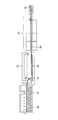
図2は、成形工程においてフロート法を用いた場合の薄板ガラスの製造装置の概略図になる。
図2の薄板ガラスの製造装置においては、まず、溶融炉21にガラス原料を投入し、溶融ガラス22とする。そして、フロートバス23内の溶融錫24上に溶融ガラスを供給し、溶融ガラスをガラスリボン25に成形する。成形されたガラスリボン25は、搬送ローラー26上に保持、搬送されることにより徐冷、冷却を行う。この際ガラスリボンを適切な冷却速度により徐冷、冷却するために、搬送ローラー26の周辺には徐冷炉27を設けることができる。そして、徐冷、冷却が行われたガラスリボンは幅方向切断装置28により所望のサイズに切断することができる。
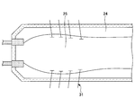
フロート法におけるガラスリボンの板厚の調整方法について図3を用いて説明する。図3は、図2のフロートバスのA-A´線における切断面を示している。
図3に示すように、フロートバス内では、溶融錫24上に図中左側から溶融ガラスが供給され、溶融錫24上を図中右側に搬送される間にガラスリボンに成形される。
ガラスリボンを補助ローラーと呼ばれる回転ローラー(トップローラー)により上から押さえることにより、ガラスリボン幅の収縮を抑え、その中央部の板厚、ガラスリボンの幅を選択、調整することができる。このように、フロート法においては、ガラスリボンの端部について回転ローラーにより押さえて成形工程を行うため、後述する図6(a)に示すように、その幅方向断面には板厚分布を生じることになる。
次に、成形工程においてフュージョン法を用いた場合の薄板ガラスの製造装置の構成の概略について図4を用いて説明する。
図4においては、溶融工程については記載を省略しているが、フロート法の場合と同様に構成することができる。
そして、溶融工程で得られた溶融ガラスを図4のフュージョンパイプ41の上面に設けられた図示しない溝に供給し、あふれ出た溶融ガラス42が、フュージョンパイプの下部で一体となり、一枚のガラスリボン43として連続的に成形される。この際、フュージョンパイプの下部で、ガラスリボンがその幅方向に縮まないようにその両端部を支持しながら成形するため、後述する図6(b)に示すようにその幅方向断面には板厚分布を生じることになる。
その後、搬送ローラー44上をガラスリボン43が搬送されることにより、徐冷、冷却される。この際フロート法の場合と同様に、例えば図中点線で示すように搬送ローラー周辺に徐冷炉を設け、徐冷工程の温度を制御することもできる。
搬送ローラー44の搬送方向下流に幅方向切断装置46が設けられている。これにより所望のサイズに切断することができる。
なお、図4においては、薄板ガラスをロール状に巻き取りガラスロールとしているが、係る形態以外にも、上述の様に所定のサイズのシート状にカットしてガラスシートとすることもできる。
図4においては搬送ローラーの配置として、水平方向にガラスリボンを搬送する部分47を含んでいるが、このようにフュージョン法による薄板ガラスの製造装置(製造方法)においても搬送経路上に水平部分を含んでいることが好ましい。
これは、本発明は製造開始時に搬送ローラーによりガラスリボンを搬送する際、ガラスリボンの先端部が自重により撓み搬送ローラーが通過できない現象を抑制しようとするものであり、係る現象は主に搬送ローラーを水平方向に並べた場所で起こり易い。このため、水平方向にガラスリボンを搬送ローラーにより搬送する搬送工程を有する方がより本発明の効果を高めることができるため好ましい。
そして、本実施形態の薄板ガラスの製造方法においては、製造開始時に、成形工程においてガラスリボンの少なくとも搬送方向先端部の板厚を、搬送工程における搬送ローラーを通過することが可能な厚さとする。さらに、ガラスリボンの搬送方向先端部が幅方向切断工程を通過後、前記成形工程で成形するガラスリボンの板厚を製品用の厚さに変更するものである。
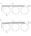
製造開始時のガラスリボンの搬送方向先端部の板厚について図5を用いて説明する。図5(a)、(b)は製造開始時のガラスリボン51の搬送方向先端部およびそれに後続する部分が搬送ローラー上を搬送される際の横断面図の構成例を示している。
図5(a)においては、ガラスリボンの先端部を含むガラスリボンの板厚52は、前記した成形工程において、搬送工程における搬送ローラーを通過することが可能な厚さに成形されており、通常の製品用の厚さよりも厚くなっている。
このため、図5(a)に示したガラスリボンは、図1に示したように当初から製品用のガラスリボンの厚さとした場合と比較して撓みにくくなり、ガラスリボンの先端部は搬送ローラーを通過することが可能になる。
この際、ガラスリボンの先端部の厚さ52を規定(選択)する方法としては以下の方法が挙げられる。
まず、生産するガラスリボンの幅と薄板ガラスの製造設備の仕様から、ローラーピッチ等のローラー仕様が決定され、該製造設備における許容たわみ量を算出することが可能になる。
一方、生産するガラスリボンの板厚、板幅と幅方向の断面形状(=板厚分布)、およびガラスの弾性率、比重から,ローラーピッチに対応する片持ち梁としての静的たわみ量を数値シミュレーション等で見積もることができる。さらに、搬送設備等の振動などを考慮して、最大動的たわみ量を見積もることができる。
そして、許容たわみ量と、最大動的たわみ量に安全係数をかけたものと、を比較して、許容たわみ量のほうが大きければ、その板厚のガラスリボンを安定して搬送すると判断することできる。
すなわち、製造設備から算出される許容たわみ量の方が、生産するガラスリボン(の形状、材質等)から算出される最大動的たわみ量と安全係数との積よりも大きくなる厚さをガラスリボンの搬送方向先端部の板厚22を搬送工程における搬送ローラーを通過することが可能な厚さとすることができる。
なお、図5(a)では、ガラスリボンが一律に厚くなる例を示したが、製造開始時にガラスリボンの少なくとも搬送方向先端部が搬送ローラーを通過することが可能な厚さであればよい。このため、例えば図5(b)のように、先端部近傍の範囲について搬送ローラーを通過できることが可能な厚さ53としてもよく、この場合の板厚53も上記と同様の計算に基づいて選択することができる。
ただし、ガラスリボンの板厚を変更するに当たっては、急激に変化させるとガラスリボンが切れることがあるため、図5(a)のように一定の範囲にわたって板厚を厚くし、その後、徐々に板厚を変化させることが好ましい。
そして、ガラスリボンは上述のように幅方向に板厚分布を有している場合がある。具体的な例を図6に示す。図6(a)は成形工程においてフロート法を用いた場合の、図6(b)は成形工程においてフュージョン法を用いた場合の、ガラスリボンの幅方向(搬送方向と垂直な方向)での断面形状を示している。
フロート法やフュージョン法により成形した場合、図6に示すように一般的にガラスリボンの中央部分611、621が製品となる部分であり、その両端部612、622は中央部よりも板厚が厚くなっている。これは、ガラスリボンの中央部分を所定の板厚とするために、成形工程においてローラー等によりガラスリボンの両端部を引張りながら、または保持しながら成形するためである。
そして、上述の様に最大動的たわみ量を算出する際にはガラスリボンの幅方向の断面形状(板厚分布)を計算の要素としている。このため、ガラスリボン全体として搬送ローラー上を通過できるように板厚を制御する際には、ガラスリボンの少なくとも先端部分の(幅方向の各部分について)板厚が所定の値となるように設定することとなる。
次いで、ガラスリボンの搬送方向先端部が前記幅方向切断工程を通過後、前記成形工程で成形するガラスリボンの板厚を製品用の厚さに変更する。
ガラスリボンの搬送方向先端部が幅方向切断工程を通過後には、成形工程から幅方向切断工程まで連続した1枚のガラスリボンとなっている。すなわち、幅方向切断工程よりも上流側には、ガラスリボンの先端部が存在しなくなる。
このように幅方向切断工程よりも上流側に搬送ローラーを通過できない原因となるガラスリボンの先端部が存在しないため、ガラスリボンの板厚を製造開始時よりも薄い製品用の板厚に変更しても、搬送ローラーを安定して通過することが可能となる。
ここで、ガラスリボンの板厚を製品用の厚さに変更するとは、図6に示したようにガラスリボンが幅方向に板厚分布を有する場合には、その中央部分の製品部611、621の部分について製品用の板厚(目的とする板厚)になる様に成形することを意味している。
ガラスリボンの板厚を製品用の厚さに変更する方法は、以下の方法から選択される1種以上の方法により行われることが好ましい。すなわち、以下の方法から選択される1種の方法のみにより行うこともでき、2種以上を組み合わせて行うこともできる。
成形工程における前記ガラスリボンの搬送速度を速くする方法。
成形工程への溶融ガラスの供給量(単位時間当たり)を少なくする(供給速度を遅くする)方法。
ガラスリボンの幅を広くする方法。
ガラスリボンの幅方向の厚さ分布を変更する方法。
上記いずれかの方法によればガラスリボンの製品部の板厚を容易に変更することが可能であるため好ましい。
なお、ガラスリボンの板厚を製品用の厚さとするのは、前述のようにガラスリボンの搬送方向先端部が幅方向切断工程を通過後すぐに行ってもよいが、さらに一定時間経過後に行っても良い。ただし、いずれの場合でも急激に成形工程におけるガラスリボンの厚さを変化させるとガラスリボンが搬送工程中に切れる場合があることから、(例えば、1時間から1日程度の時間をかけて)徐々にガラスリボンの板厚を薄くしていき、最終的に製品用の厚さとすることが好ましい。
また、複数種類の板厚のガラスの生産を予定している場合には、ガラスリボンの板厚を薄くする過程を利用して、板厚の厚い製品をその厚さの順に生産し、最終的にガラスリボンの板厚を最も板厚の薄い製品にあわせて(変更して)生産することが生産性の観点から好ましい。すなわち、例えば最初は板厚が厚目のロットのガラス(例えば0.7mm以上)を生産し、次に、板厚の薄いロットのガラス(例えば0.3mm)を生産して、その後に特に板厚の薄いロットのガラス(例えば0.2mm以下)を生産してもよい。
そして、本実施形態で説明した薄板ガラスの製造方法において、前述した幅方向切断工程に加えて、ガラスリボンの幅方向両端部(耳部)を切断する両端部切断工程を有することができる。この点について以下に説明する。
上記のように被切断物であるガラスリボンは例えばフロート法やフュージョン法により成形されたものが、搬送工程の間に冷却されたものである。そして、フロート法やフュージョン法により成形されたガラスリボンは後述のようにその幅方向の両端部に中央部とは厚さの違う部分を生じる場合がある。このため、製品の幅方向の両端部についても切断することとなる。この点について図7を用いて説明する。
図7(a)は、ガラスリボンを上面から見た図であり、図7(b)は、図7(a)において、ガラスリボンを矢印Aの方向から見たガラスリボンの幅方向の断面図を示している。
図7(b)は、既に示したようにフュージョン法により成形した場合のガラスリボンの幅方向の断面図であるが、この場合、ガラスリボンの搬送方向(図7(a)中ブロック矢印で示した方向)と垂直方向の断面はその両端部71は製品となる中央部72よりも板厚が厚くなっている。
ガラスリボンが係る形状を有する場合、所望の長さの薄板ガラスとするための図7(a)のに示す点線Yでの幅方向切断に加えて、係る両端部(耳部)71を除去するために図7(a)に示す点線Xにおいても切断することができる。
点線Xと点線Yいずれを先に切断することもできるが、点線Xを切断した後、点線Yを切断することが好ましい。
すなわち、幅方向切断工程より前に、ガラスリボンの幅方向両端部を切断する両端部切断工程を有することが好ましい。
両端部切断工程、幅方向切断工程について図8を用いて説明する。
図8(a)はガラスリボンについて上記手順により切断しているところを上面側からみた構成を模式的に示しており、図8(b)は、図8(a)において、矢印Bから見た側面の模式図を示している。
両端部切断工程、幅方向切断工程においては、切断の際に発生するガラス片等が搬送経路上に残留しないよう、複数の搬送ローラー81により、幅方向切断装置84まで搬送されている。
また、幅方向切断装置84までは成形工程から連続する1枚のガラスリボン82となっている。
図8に示すように搬送ローラー81により連続的に搬送されてくるガラスリボン82について、まずその幅方向両端部を切断するため、図中点線Xで示す切断線に沿って、両端部切断装置83により切断を行う。
そして、その後さらに搬送ローラー81によりガラスリボンは搬送され、幅方向切断装置84により、所望の薄板ガラスの長さになるように切断され、ベルトコンベアー85により図示しない製品置き場等へと搬送されることとなる。
この場合、両端部切断装置83によりガラスリボンの両端部を切断する前は、上述のように両端部の板厚が厚いため、図8(b)に示すようにガラスリボンの最大厚さとしてはT1の厚みを有している。
ところが、両端部切断装置83を通過後のガラスリボンの最大厚さはT1よりも薄いT2となる。これは、図7(b)で説明したように、両端部切断装置通過後のガラスリボンは、板厚の薄い製品部(中央部)72のみとなっているためである。
このため、ガラスリボンのうち、両端部切断装置を通過後の部分については特に板厚が薄いため撓みやすくなっている。従って、製造開始当初からガラスリボンの搬送方向先端部の製品部について目標とする板厚とした場合には、両端部切断装置と幅方向切断装置との間の搬送ローラーをより通過しにくくなる。
これに対して本実施形態の薄板ガラスの製造方法においては、ガラスリボンの搬送方向の先端部の厚さを製造開始時においては厚くし、その先端部が幅方向切断装置を通過後(幅方向切断工程を通過後)ガラスリボンの板厚を変更する。このため、ガラスリボンの先端部は幅方向切断装置部分にまでより確実に到達することが可能になる。
ここで説明した幅方向切断工程、両端部切断工程における具体的な切断方法は限定されるものではなく、例えば割断や、レーザー光を用いた溶断により行うことができる。また、幅方向切断工程と、両端部切断工程とで異なる切断方法を用いても良い。
割断により切断する場合、一般的に割断は折り筋(スクライブ線)をつけるスクライブ工程と、スクライブ工程で形成したスクライブ線を起点として実際にガラスリボンを分断(切断)する割断工程との2段階の工程により行われる。
そして、上述のように両端部切断工程後に幅方向切断工程を行うとは、(例えば両切断工程を割断により行う場合)ガラスリボン両端部(耳部)について実際に分断する割断工程の後に、幅方向について実際に分断する割断工程を行えば良く、それぞれの部分についてのスクライブ工程の順序は問わない。
すなわち、例えばガラスリボン両端部についてのスクライブ工程、及び、幅方向についてのスクライブ工程(スクライブ工程の順序は問わない)を行った後に、ガラスリボン両端部を分断する割断工程、幅方向に沿って分断する割断工程をその順に行う方法であっても良い。
また、それぞれの切断工程についてスクライブ工程、割断工程を順に行ってもよい。つまり、ガラスリボン両端部についてのスクライブ工程、ガラスリボン両端部を分断する割断工程を行った後、ガラスリボンの幅方向についてのスクライブ工程、ガラスリボンの幅方向に沿って分断する割断工程の順に行っても良い。
本実施形態の薄板ガラスの製造方法において、ここで説明した順に両端部切断工程、幅方向切断工程を適用する場合、前記成形工程で成形するガラスリボンの製品用の厚さであって、ガラスリボンの幅方向中央部(製品部)の板厚が0.3mm以下であることが好ましい。
これは、製造開始時にその搬送方向先端部の幅方向中央部(製品部)の板厚を上記範囲としたガラスリボンを供給した場合、特に両端部切断装置以後の搬送ローラーを通過できなくなりやすいところ、本実施形態で説明した方法によれば搬送ローラーをより確実に通過することが可能になり、特に効果を発揮するためである。
また、上記ガラスリボンの幅方向中央部の板厚は0.2mm以下であることがより好ましく、0.15mm以下であることがさらに好ましく、0.1mm以下であることが特に好ましい。
ガラスリボンの幅方向中央部(製品部)の板厚の下限値については特に限定されるものではないが、成形工程から幅方向切断工程までガラスリボンが搬送中に切れない厚さにその搬送速度、ガラスの種類、特性等に応じて選択することが好ましい。例えば、ガラスリボンの幅方向中央部の板厚の下限値は、ガラス成形原理による安定生産条件より、0.01mm以上が好ましく、0.02mm以上がより好ましく、0.03mm以上であることが特に好ましい。
ここでいうガラスリボンの幅方向中央部の板厚とは、前記ガラスリボンの搬送方向先端部が前記幅方向切断工程を通過後、前記成形工程で成形するガラスリボンの板厚を製品用の厚さに変更した際、例えば図6における製品部(中央部)612、622の板厚を意味している。
なお、図7(a)に示す点線Yを切断した後、点線Xを切断する場合、すなわち、幅方向切断工程を先に行った後に両端部切断工程を行う場合、前記成形工程で成形するガラスリボンの製品用の厚さであって、ガラスリボンの幅方向中央部の板厚は0.2mm以下であることが好ましい。
これは、従来の様に製造開始時から係る板厚に成形した場合にはガラスリボンの先端部が幅方向切断工程まで搬送ローラーを通過できないのに対して、本実施形態の製造方法では確実に幅方向切断工程まで搬送ローラーを通過することができる様になりその効果を発揮するためである。
そして、既述の様にガラスリボンの先端部が幅方向切断工程に到達後は、成形工程から幅方向切断工程まで連続した1枚のガラスリボンとなっており、幅方向切断工程よりも上流側には、ガラスリボンの先端部が存在しなくなる。このように幅方向切断工程よりも上流側に搬送ローラーを通過できない原因となるガラスリボンの先端部が存在しなくなると、ガラスリボンの板厚を、製造開始時よりも薄い上記範囲の製品用の板厚に変更しても、搬送ローラーを通過することが可能となる。
幅方向切断工程通過後のガラスは、室温に近い温度まで下がっているため、前述した搬送ローラーの径やピッチの制約は軽減され、種々の搬送方法(小径の搬送ローラーや、ベルト搬送、エア浮上搬送など)を選択することができる。
また、上記ガラスリボンの幅方向中央部の板厚は0.15mm以下であることがより好ましく、0.1mm以下であることが特に好ましい。
なお、ガラスリボンの製品部の板厚とは上述したとおりである。また、ガラスリボンの幅方向中央部(製品部)の板厚の下限値についても上述のように特に限定されるものではなく、成形工程から幅方向切断工程までガラスリボンが搬送中に切れない厚さにその搬送速度、ガラスの種類、特性等に応じて選択することができる。具体的には例えば、ガラス成形原理による安定生産条件より、0.01mm以上が好ましく、0.02mm以上がより好ましく、0.03mm以上であることが特に好ましい。
以上、説明してきた本実施形態の薄板ガラスの製造方法によれば、製造開始時(製造装置立ち上げ時)において搬送ローラー上をガラスリボンがより確実に通過することが可能になり、歩留向上及び生産性向上が図れる。
以下に具体的な実施例、比較例を挙げて説明するが、本発明はこれらの実施例に限定されるものではない。
[実施例1]
本実施例においては、以下の手順により薄板ガラスの製造を行った。
(溶融工程)無アルカリガラスとなるようにガラス原料を混合しこれを、溶融炉に供給して溶融ガラスとした。
(成形工程)溶融炉からの溶融ガラスをフロートバスの溶融錫上に供給し、ガラスリボンに成形した。
[実施例1]
本実施例においては、以下の手順により薄板ガラスの製造を行った。
(溶融工程)無アルカリガラスとなるようにガラス原料を混合しこれを、溶融炉に供給して溶融ガラスとした。
(成形工程)溶融炉からの溶融ガラスをフロートバスの溶融錫上に供給し、ガラスリボンに成形した。
この際、製造開始時にはガラスリボンはその板幅が4.6m、中央部(製品部)(図6(a)中611部分)の厚さが0.3mmになるように連続的に成形した。係るガラスリボンの形状は予め製造設備の許容たわみ量が、ガラスリボンの最大動的たわみ量と安全係数との積よりも大きくなることを確認したものである。
(搬送工程)ローラーピッチが450mmに設定され、複数本配置された搬送ローラー上を前記成形工程で成形したガラスリボンを搬送した。
(幅方向切断工程)搬送工程により切断装置まで搬送されたガラスリボンについて所望の長さになるようにガラスリボンを切断した。
(両端部切断工程)幅方向切断工程において所望の長さとなったガラスシートについて、その幅方向の両端部について切断を行った。
(搬送工程)ローラーピッチが450mmに設定され、複数本配置された搬送ローラー上を前記成形工程で成形したガラスリボンを搬送した。
(幅方向切断工程)搬送工程により切断装置まで搬送されたガラスリボンについて所望の長さになるようにガラスリボンを切断した。
(両端部切断工程)幅方向切断工程において所望の長さとなったガラスシートについて、その幅方向の両端部について切断を行った。
すなわち、図7(a)におけるYの切断線で切断を行ってから、Xの切断線で切断を行った。
そして、上記製造工程において、幅方向切断工程をガラスリボンの先端部が通過することを確認してから、前記成形工程において、成形するガラスリボンの形状として、板幅は4.6mのままとし、その製品部の板厚(図6(a)中の611部分)を0.1mmに変更した。製品部の板厚の変更は、図3に示したトップローラーにより、ガラスリボン内の幅方向の板厚分布を変更すること、および、ガラスリボンの搬送速度を速くする方法、さらに、溶融ガラスの供給量を少なくする方法を組み合わせることにより行った。
本実施例においては、製造開始時においてもガラスリボンの搬送方向先端部が幅方向切断工程を通過することができた。また、製品部の板厚を変更した後も切れることなく継続的にガラスリボンが搬送ローラー上を搬送されていることを確認できた。
[比較例1]
本比較例においては、成形工程において、製造開始時にガラスリボンをその最終製品の目的とするサイズとした、すなわち、その板幅が4.6m、中央部(製品部)の厚さが0.1mmになるように成形した点以外は実施例1と同様にして薄板ガラスの製造を開始した。
[比較例1]
本比較例においては、成形工程において、製造開始時にガラスリボンをその最終製品の目的とするサイズとした、すなわち、その板幅が4.6m、中央部(製品部)の厚さが0.1mmになるように成形した点以外は実施例1と同様にして薄板ガラスの製造を開始した。
この際、上記ガラスリボンの形状は、製造設備の許容たわみ量が、ガラスリボンの最大動的たわみ量と安全係数との積よりも小さくなっていた。
本比較例の条件により薄板ガラスの製造を開始したところ、成形工程において成形したガラスリボンは、搬送工程の搬送ローラー上を通過することができず、幅方向切断工程に到達することができなかったため、目的の仕様の薄板ガラスを生産することができなかった。
本発明は、板ガラスなどの製造に好適である。
本出願は、2012年8月9日に日本国特許庁に出願された特願2012-177513に基づくものであり、その出願を優先権主張するものであり、その出願の全ての内容を参照することにより包含するものである。
22、42 溶融ガラス
25、43、51、82 ガラスリボン
26、44、81 搬送ローラー
25、43、51、82 ガラスリボン
26、44、81 搬送ローラー
Claims (7)
- ガラス原料を溶融し、溶融ガラスとする溶融工程と、
溶融ガラスを成形しガラスリボンとする成形工程と、
前記ガラスリボンを搬送ローラーにより搬送する搬送工程と、
ガラスリボンを幅方向に切断する幅方向切断工程と、を有し、
製造開始時に、前記成形工程においてガラスリボンの少なくとも搬送方向先端部の板厚を、前記搬送工程における搬送ローラーを通過することが可能な厚さとし、
前記ガラスリボンの搬送方向先端部が前記幅方向切断工程を通過後、前記成形工程で成形するガラスリボンの板厚を製品用の厚さに変更する薄板ガラスの製造方法。 - 前記成形工程で成形するガラスリボンの板厚を製品用の厚さに変更する方法は、
前記成形工程における前記ガラスリボンの搬送速度を速くする方法と、
前記成形工程への溶融ガラスの供給量を少なくする方法と、
前記ガラスリボンの幅を広くする方法と、
前記ガラスリボンの幅方向の厚さ分布を変更する方法と、から選択される1種以上の方法により行われることを特徴とする請求項1に記載の薄板ガラスの製造方法。 - 前記幅方向切断工程より前に、前記ガラスリボンの幅方向両端部を切断する両端部切断工程を有する請求項1または2に記載の薄板ガラスの製造方法。
- 前記成形工程で成形するガラスリボンの製品用の厚さであって、ガラスリボンの幅方向中央部の板厚が0.3mm以下であることを特徴とする請求項3に記載の薄板ガラスの製造方法。
- 前記成形工程で成形するガラスリボンの製品用の厚さであって、ガラスリボンの幅方向中央部の板厚が0.2mm以下であることを特徴とする請求項1乃至4いずれか一項に記載の薄板ガラスの製造方法。
- 前記ガラスリボンの板厚を製品用の厚さに変更した後の、前記ガラスリボンの幅が1.5m以上である請求項1乃至5いずれか一項に記載の薄板ガラスの製造方法。
- 前記搬送工程における搬送ローラーのローラーピッチが200mm以上である請求項1乃至6いずれか一項に記載の薄板ガラスの製造方法。
Applications Claiming Priority (2)
| Application Number | Priority Date | Filing Date | Title |
|---|---|---|---|
| JP2012177513A JP2015187041A (ja) | 2012-08-09 | 2012-08-09 | 薄板ガラスの製造方法 |
| JP2012-177513 | 2012-08-09 |
Publications (1)
| Publication Number | Publication Date |
|---|---|
| WO2014024641A1 true WO2014024641A1 (ja) | 2014-02-13 |
Family
ID=50067877
Family Applications (1)
| Application Number | Title | Priority Date | Filing Date |
|---|---|---|---|
| PCT/JP2013/069180 Ceased WO2014024641A1 (ja) | 2012-08-09 | 2013-07-12 | 薄板ガラスの製造方法 |
Country Status (3)
| Country | Link |
|---|---|
| JP (1) | JP2015187041A (ja) |
| TW (1) | TW201410621A (ja) |
| WO (1) | WO2014024641A1 (ja) |
Cited By (1)
| Publication number | Priority date | Publication date | Assignee | Title |
|---|---|---|---|---|
| CN111018320A (zh) * | 2019-12-26 | 2020-04-17 | 彩虹(合肥)液晶玻璃有限公司 | 一种拉制玻璃带的牵引辊结构 |
Citations (6)
| Publication number | Priority date | Publication date | Assignee | Title |
|---|---|---|---|---|
| JP2006525150A (ja) * | 2003-04-04 | 2006-11-09 | コーニング インコーポレイテッド | 光学用途のための高強度積層板 |
| JP2007197303A (ja) * | 2005-09-29 | 2007-08-09 | Nippon Electric Glass Co Ltd | 板ガラス成形装置搭載用耐火物成形体の成形方法、耐火物成形体、及び板ガラス成形方法と板ガラス |
| JP2008256290A (ja) * | 2007-04-06 | 2008-10-23 | Matsushita Electric Ind Co Ltd | 熱処理装置および被熱処理物の排出方法 |
| WO2011118547A1 (ja) * | 2010-03-23 | 2011-09-29 | 日本電気硝子株式会社 | ガラス基板の製造方法及びガラス基板 |
| JP2012025624A (ja) * | 2010-07-23 | 2012-02-09 | Nippon Electric Glass Co Ltd | ガラスフィルムの製造装置および製造方法 |
| JP2012096987A (ja) * | 2010-10-29 | 2012-05-24 | Corning Inc | ガラス溶融物の速度および厚さ分布が改善されたオーバーフローダウンドロー法 |
-
2012
- 2012-08-09 JP JP2012177513A patent/JP2015187041A/ja active Pending
-
2013
- 2013-07-12 WO PCT/JP2013/069180 patent/WO2014024641A1/ja not_active Ceased
- 2013-07-19 TW TW102125973A patent/TW201410621A/zh unknown
Patent Citations (6)
| Publication number | Priority date | Publication date | Assignee | Title |
|---|---|---|---|---|
| JP2006525150A (ja) * | 2003-04-04 | 2006-11-09 | コーニング インコーポレイテッド | 光学用途のための高強度積層板 |
| JP2007197303A (ja) * | 2005-09-29 | 2007-08-09 | Nippon Electric Glass Co Ltd | 板ガラス成形装置搭載用耐火物成形体の成形方法、耐火物成形体、及び板ガラス成形方法と板ガラス |
| JP2008256290A (ja) * | 2007-04-06 | 2008-10-23 | Matsushita Electric Ind Co Ltd | 熱処理装置および被熱処理物の排出方法 |
| WO2011118547A1 (ja) * | 2010-03-23 | 2011-09-29 | 日本電気硝子株式会社 | ガラス基板の製造方法及びガラス基板 |
| JP2012025624A (ja) * | 2010-07-23 | 2012-02-09 | Nippon Electric Glass Co Ltd | ガラスフィルムの製造装置および製造方法 |
| JP2012096987A (ja) * | 2010-10-29 | 2012-05-24 | Corning Inc | ガラス溶融物の速度および厚さ分布が改善されたオーバーフローダウンドロー法 |
Cited By (2)
| Publication number | Priority date | Publication date | Assignee | Title |
|---|---|---|---|---|
| CN111018320A (zh) * | 2019-12-26 | 2020-04-17 | 彩虹(合肥)液晶玻璃有限公司 | 一种拉制玻璃带的牵引辊结构 |
| CN111018320B (zh) * | 2019-12-26 | 2021-03-09 | 彩虹(合肥)液晶玻璃有限公司 | 一种拉制玻璃带的牵引辊结构 |
Also Published As
| Publication number | Publication date |
|---|---|
| JP2015187041A (ja) | 2015-10-29 |
| TW201410621A (zh) | 2014-03-16 |
Similar Documents
| Publication | Publication Date | Title |
|---|---|---|
| KR101736262B1 (ko) | 유리 필름의 제조방법 및 그 제조장치 | |
| JP5933655B2 (ja) | ガラス帯体をドロー成形する方法 | |
| JP6108234B2 (ja) | 板ガラスの製造方法、及び製造装置 | |
| JP5656080B2 (ja) | ガラス基板の製造方法 | |
| CN106660849B (zh) | 柔性玻璃带的连续加工 | |
| CN107667075B (zh) | 使带隔离和稳定来连续处理挠性玻璃带 | |
| KR102902259B1 (ko) | 초박형 유리의 길이 절단을 위한 디바이스 및 방법 | |
| KR101833809B1 (ko) | 유리판의 제조 방법 | |
| JP7160691B2 (ja) | 溶融ガラスの成形方法、成形装置、およびガラス製品の製造方法 | |
| WO2017208677A1 (ja) | ガラスフィルムの製造方法 | |
| US20190010072A1 (en) | Method and apparatus for continuous processing of a flexible glass ribbon | |
| CN104803593A (zh) | 玻璃板的制造方法及玻璃板 | |
| JP2015044709A (ja) | ガラスフィルムリボン製造方法及びガラスフィルムリボン製造装置並びにガラスロール | |
| JP6056711B2 (ja) | 薄板ガラスの切断方法、およびガラス物品の製造方法 | |
| JP2003306340A (ja) | ガラス基板及びその製造方法並びにその製造装置 | |
| CN107735369A (zh) | 玻璃基板的制造方法及玻璃基板制造装置 | |
| JP2015187041A (ja) | 薄板ガラスの製造方法 | |
| JP2014152046A (ja) | ガラス板成形装置、及びガラス板成形方法 | |
| JP2014189421A (ja) | スクライブ線加工装置、スクライブ線加工方法および板ガラスの製造方法 | |
| JPWO2011136122A1 (ja) | ガラス板の製造方法及びその装置 | |
| KR102874726B1 (ko) | 유리 물품의 제조 방법 | |
| JP6500439B2 (ja) | ガラスロール | |
| CN103857633B (zh) | 薄板玻璃的制造方法以及玻璃基板的制造方法 | |
| JP2014051404A (ja) | ガラス板の製造方法 |
Legal Events
| Date | Code | Title | Description |
|---|---|---|---|
| 121 | Ep: the epo has been informed by wipo that ep was designated in this application |
Ref document number: 13828083 Country of ref document: EP Kind code of ref document: A1 |
|
| NENP | Non-entry into the national phase |
Ref country code: DE |
|
| 122 | Ep: pct application non-entry in european phase |
Ref document number: 13828083 Country of ref document: EP Kind code of ref document: A1 |
|
| NENP | Non-entry into the national phase |
Ref country code: JP |