WO2014024631A1 - Dispositif d'actionnement et réfrigérateur/congélateur - Google Patents
Dispositif d'actionnement et réfrigérateur/congélateur Download PDFInfo
- Publication number
- WO2014024631A1 WO2014024631A1 PCT/JP2013/069048 JP2013069048W WO2014024631A1 WO 2014024631 A1 WO2014024631 A1 WO 2014024631A1 JP 2013069048 W JP2013069048 W JP 2013069048W WO 2014024631 A1 WO2014024631 A1 WO 2014024631A1
- Authority
- WO
- WIPO (PCT)
- Prior art keywords
- function
- operating device
- light source
- light
- user
- Prior art date
Links
Images


Classifications
-
- G—PHYSICS
- G09—EDUCATION; CRYPTOGRAPHY; DISPLAY; ADVERTISING; SEALS
- G09F—DISPLAYING; ADVERTISING; SIGNS; LABELS OR NAME-PLATES; SEALS
- G09F23/00—Advertising on or in specific articles, e.g. ashtrays, letter-boxes
- G09F23/0058—Advertising on or in specific articles, e.g. ashtrays, letter-boxes on electrical household appliances, e.g. on a dishwasher, a washing machine or a refrigerator
-
- F—MECHANICAL ENGINEERING; LIGHTING; HEATING; WEAPONS; BLASTING
- F25—REFRIGERATION OR COOLING; COMBINED HEATING AND REFRIGERATION SYSTEMS; HEAT PUMP SYSTEMS; MANUFACTURE OR STORAGE OF ICE; LIQUEFACTION SOLIDIFICATION OF GASES
- F25D—REFRIGERATORS; COLD ROOMS; ICE-BOXES; COOLING OR FREEZING APPARATUS NOT OTHERWISE PROVIDED FOR
- F25D29/00—Arrangement or mounting of control or safety devices
-
- G—PHYSICS
- G09—EDUCATION; CRYPTOGRAPHY; DISPLAY; ADVERTISING; SEALS
- G09F—DISPLAYING; ADVERTISING; SIGNS; LABELS OR NAME-PLATES; SEALS
- G09F13/00—Illuminated signs; Luminous advertising
- G09F13/04—Signs, boards or panels, illuminated from behind the insignia
-
- F—MECHANICAL ENGINEERING; LIGHTING; HEATING; WEAPONS; BLASTING
- F25—REFRIGERATION OR COOLING; COMBINED HEATING AND REFRIGERATION SYSTEMS; HEAT PUMP SYSTEMS; MANUFACTURE OR STORAGE OF ICE; LIQUEFACTION SOLIDIFICATION OF GASES
- F25D—REFRIGERATORS; COLD ROOMS; ICE-BOXES; COOLING OR FREEZING APPARATUS NOT OTHERWISE PROVIDED FOR
- F25D2400/00—General features of, or devices for refrigerators, cold rooms, ice-boxes, or for cooling or freezing apparatus not covered by any other subclass
- F25D2400/36—Visual displays
- F25D2400/361—Interactive visual displays
Definitions
- the present invention relates to an operating device and a refrigerated freezer equipped with the operating device.
- Conventional refrigerated freezers mainly have a plurality of rooms with different temperature zones in order to cope with diversification of eating habits.
- a user can freely set a function, for example, a function of changing the temperature, performance, etc. of each room.
- the user can set a function to lower or increase the temperature of each room by a predetermined temperature, a function to change the performance to a rapid cooling mode in which the cooling capacity is temporarily increased, and a power saving mode in which power consumption is suppressed. It is possible to set a function for changing the performance.
- the user can freely set the function of changing the performance to a refrigeration mode in which the room temperature is above the freezing point or a freezing mode in which the room temperature is below the freezing point.
- a refrigerator-freezer an operation device is provided on the surface of the door, and the user operates the operation device to select and set a function, or set the selected function in more detail. It is possible to
- the operating device is arranged on the back side of the surface part provided with a layer having a notation part on which display elements such as symbols and words are indicated by printing or the like, and a light source such as a light emitting diode (LED) is provided.
- JP 2011-47550 A paragraphs [0021]-[0023], FIG. 3)
- the light source is arranged so that the optical axis faces the user's line of sight, so the light emitting part of the light source enters the user's field of view, and the user There was a problem that it was difficult to read display elements. Moreover, even if the light source is arranged so that the optical axis does not face the user's line of sight, that is, the optical axis is parallel to the surface of the surface component, the light emitted from the light source is centered on the optical axis. Due to the spread angle, the light emitting part of the light source still enters the user's field of view, and there is a problem that it is difficult for the user to read display elements such as symbols and words.
- the present invention has been made to solve the above-described problems, and provides an operating device that improves the reading difficulty of display elements and a refrigerated freezer equipped with the operating device.
- the operating device includes a layer having a plurality of notation parts in which information used for operation is represented by at least one of a transmissive part and a non-transmissive part, and a back side of the layer. And at least one light emitting member that emits incident light from the surface and the notation part, and is arranged so that the optical axis is substantially parallel to the layer.
- a plurality of light sources that make light incident on the light emitting member, at least a part of the plurality of notation portions form at least three sections, and the three sections are formed in a row, and the 3 When a figure that includes the three sections and has a minimum total perimeter is drawn, the figure has a width dimension in a direction perpendicular to the column direction of the column.
- the light source provided corresponding to at least one of the notation portions that forms a section located in the center of the three sections has an optical axis substantially perpendicular to the column direction of the columns. It is arranged like this.
- At least a part of the plurality of notation units corresponds to at least one notation unit that forms at least three sections in a row and forms a section located in the center among the three sections.
- the provided light source is arranged so that the optical axis is substantially perpendicular to the column direction of the column, so that when the orientation of the user's line of sight changes, the light source of the light source enters the user's field of view Therefore, the reading difficulty of the display element is improved.
- FIG. 1 shows the cross-section of the display means which displays the icon for selecting the function which the user of the operating device which concerns on Embodiment 1 of this invention contacts and sets. It is a front view in the state where the 1st layer of the display means which displays the icon for selecting the function which the user of the operating device concerning Embodiment 1 of the present invention contacts and sets is removed. It is a front view in the state with the 1st layer of the display means which displays the icon for selecting the function which the user of the operating device concerning Embodiment 1 of this invention contacts and sets. It is the figure which overlapped and described the 1st light source on the figure which shows the state by which all the display elements of the operating device which concern on Embodiment 1 of this invention were displayed.
- the operating device is mounted in a refrigerated freezer.
- the operating device according to the present invention includes a refrigerated freezer having a different configuration from that described, and other devices.
- An operating device mounted on the device is included.
- terms indicating directions for example, “front”, “back”, “up”, “down”, “left”, “right”, etc.
- the present invention is not limited by the terms.
- symbol is attached
- the illustration of the fine structure is simplified or omitted as appropriate.
- overlapping descriptions are simplified or omitted as appropriate.
- Embodiment 1 FIG. The operating device according to Embodiment 1 will be described below. (Structure of freezer refrigerator) First, the structure of the refrigeration freezer in which the operating device according to Embodiment 1 is mounted will be described.
- 1 is a front view of a refrigerated freezer in which an operating device according to Embodiment 1 is mounted.
- the refrigerated freezer 1 includes a refrigerated room 2, an ice making room 3, a temperature switching room 4, a freezer room 5, and a vegetable room 6.
- the refrigerator compartment 2 is provided with doors 2a and 2b. The doors 2a and 2b can be opened and closed by rotating around the hinge.
- the ice making chamber 3 has an ice storage case inside, and water supplied to a tank provided in the refrigerator compartment 2 is automatically made and stored.
- the temperature switching chamber 4 can switch between the refrigeration mode and the freezing mode, and can be set to an arbitrary temperature.
- An operating device 7 is provided on the surface of the door 2 a provided in the refrigerator compartment 2.
- the front direction of the refrigerated freezer 1 is described as “front side” and the back direction is described as “back side”.
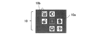
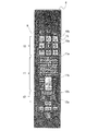
- FIG. 2 is a diagram illustrating a state in which all display elements of the operating device according to the first embodiment are displayed.
- a surface component 8 is provided on the surface of the operating device 7.
- a plurality of display elements 9 are displayed on the surface component 8.
- the display element 9 is displayed when the light source of the display means provided on the back side of the front surface component 8 is turned on by a control means (not shown). Information necessary for the operation is written on each of the display elements 9.
- a display means is provided for each of the display elements 9.
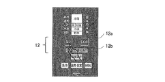
- At least a part of the display element 9 is collected for each use of the written information, and the function selection section 10 (note that the function selection section 10 is a “notation section in which information for selecting a function is written” in the present invention. ”And a function explanation section 11 (note that the function explanation section 11 is represented with“ information for explaining the function ”in the present invention. "Corresponding to" section “formed by” notation section “including at least notation section") and function setting section 12 (note that function setting section 12 is represented by “information for setting functions” in the present invention. And “partition” formed by “notation part” including at least “notation part”.).
- the function selection section 10, the function explanation section 11, and the function setting section 12 are provided in a line. In this example, a case is shown in which each section is provided in a vertical row, but it may be provided in a horizontal row or may be provided in a row in another direction.
- an icon 10a for starting an operation for setting a function by contact with the user, and a function set by touching the user are selected for each set function.
- Icon 10b for displaying For example, the function explanation section 11 corresponds to the word 11a for asking whether to set the function while explaining the function corresponding to the icon 10b selected by the user, and the icon 10b selected by the user. A symbol 11b for explaining the room where the function operates is displayed.
- the function setting section 12 includes, for example, an icon 12a for setting or canceling a function selected by contact with the user, and a wording 12b for notifying the user that the function is set or cancelled. Is displayed.
- Each display element 9 may be displayed at a different position in the section.
- the word 11a is displayed above the symbol 11b.
- the present invention is not limited to this, and the symbol 11b may be displayed above the word 11a.
- the word 11a is displayed above the symbol 11b
- the relevance between the icon 10b and the word 11a is emphasized.
- the symbol 11b is displayed above the word 11a, the relevance between the icon 10b and the symbol 11b is emphasized.
- the display component 9 other than the display elements 9 forming the function selection section 10, the function explanation section 11, and the function setting section 12 may or may not be displayed on the surface component 8.
- display means, input means, and the like for setting functions other than the function corresponding to the icon 10b or setting the selected function in more detail are provided below the function setting section 12.
- These display means and input means may be provided on the upper side of the function selection section 10 or between the sections, or may be provided at a position outside the row of sections.
- the icon 10a is provided at the center of the function selection section 10, and is always displayed and visible.
- the icon 10a has a function as an input unit that is first contacted when the user sets a function.
- the icon 10b has a function as an input means. The user selects a function to be set by touching the icon 10b.
- the icon 10b is marked with a function reminiscent of the function itself set when the icon 10b is selected or a scene where the function is used.
- One wording 11a is prepared for each icon 10b.
- the wording corresponding to the selected icon 10b is displayed.
- the symbol 11b displays a room in which a function corresponding to the icon 10b selected by the user operates and allows the user to recognize the room.
- the function corresponding to the icon 10b selected by the word 11a or the symbol 11b is described, the user can recognize the action when the function is set without reading the instruction manual or the like. it can.
- the wording 11a and the symbol 11b may have a function as an input unit as necessary.
- Symbols (characters) such as “Yes” and “No” are written on the icon 12a.
- the icon 12a has a function as an input means, and the user selects and touches a symbol (character) such as “Yes” or “No” so that the user responds to the word 11a, thereby selecting the selected icon 10b.
- the function corresponding to is set or canceled.
- the wording 12b includes a wording that informs the user that the function has been set or canceled when the icon 12a is selected. By displaying the wording 12b, the user can recognize the completion of the operation.
- FIG. 2 shows a case where a word indicating that the function is set is written.
- a word notifying that the function has been released may be written, and both a word notifying that the function has been set and a word notifying that the function has been released may be written.
- the wording 12b may not be displayed as necessary, and the operation device according to the present invention includes an operation device in which the wording 12b is not displayed.
- the wording 12b may have a function as an input unit as necessary.
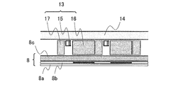
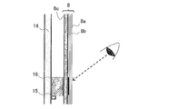
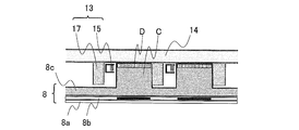
- FIG. 3 is a diagram illustrating a cross-sectional structure of a display unit that displays surface components of the operating device according to the first embodiment and display elements that do not have a function as an input unit.
- the display means 13 is provided between the surface component 8 and the printed board 14.
- the surface component 8 is provided with a first layer 8a on which the basic color and pattern of the operating device 7 are written, and a second layer 8b on which the display element 9 is written.
- the first layer 8a is provided on the most surface side of the surface component 8, and the second layer 8b is provided on the back surface side of the first layer 8a.
- the second layer 8b is formed with a transmissive portion, and each display element 9 is represented by the shape of the transmissive portion (the second layer 8b corresponds to the “layer” in the present invention.
- the second layer Each area where the display element 9 of 8b is written corresponds to a “notation part” in the present invention.
- the first layer 8a and the second layer 8b are formed integrally with a member 8c having permeability such as resin.
- each display element 9 may be represented by the shape of the non-transmissive portion, or each display element 9 may be represented by appropriately using the shapes of the transmissive portion and the non-transmissive portion.
- a transmissive part with high transparency and a transmissive part with low transparency may be formed, and each display element 9 may be represented by the shape of the transmissive part with high transparency or the transmissive part with low transparency.
- the display means 13 includes a first light source 15, a light guide plate 16, and a shielding wall 17 (note that the light guide plate 16 corresponds to a “light emitting member” in the present invention).
- One display means 13 is provided for each display element 9 of the second layer 8 b of the surface component 8.
- One or a plurality of first light sources 15 are provided for each display unit 13, and the optical axis is provided in parallel with the surface of the surface component 8.
- the light guide plate 16 bends light from the first light source 15 provided on the side by 90 ° by a reflection action, and emits planar light to the surface component 8 side.
- the surface component 8 has a certain thickness, for example, 2 mm or more due to molding restrictions.
- the surface component 8 may be integrated with the light guide plate 16 provided on the back surface side.
- the surface component 8 functions as a light guide layer together with the light guide plate 16.
- the first light source 15 can be lit with varying luminance.
- the display element 9 written on the second layer 8b is hidden by the first layer 8a, and the user cannot visually recognize the display element 9.
- the first light source 15 is turned on, the light is transmitted through the transmission part of the second layer 8b, so that the display element 9 written on the second layer 8b floats on the surface of the first layer 8a. Go up.
- the shielding wall 17 is provided and it is possible to display the display element 9 separately. Note that a part of the light passing through the transmissive member 8c also reaches the region between the display elements 9 of the second layer 8b, but each display element 9 is indicated by the shape of the transmissive portion. Since a non-transmissive portion is formed in the region between the display elements 9 of the second layer 8b, it is possible to display only the display element 9 provided with the lit first light source 15 more clearly. .
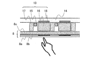
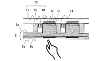
- FIG. 4 is a diagram illustrating a cross-sectional structure of the display unit that displays the surface component of the operating device according to the first embodiment and the display element having a function as an input unit.
- the display unit 13 includes a first light source 15, a light guide plate 16, a shielding wall 17, and an input unit 18.
- the input means 18 is an electrode of a capacitive touch sensor.
- the input means 18 is attached to the surface of the printed circuit board 14.
- the input means 18 is provided on the back side of the light guide plate 16 provided for each display element 9.
- the input means 18 detects that the capacitance value changes via the surface component 8 and the light guide plate 16 when the user touches the area where the display element 9 of the surface component 8 is displayed, and controls the input means 18.
- a signal is transmitted to (not shown).
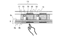
- FIG. 5 is a diagram illustrating a cross-sectional structure of a display unit that displays an icon for selecting a function to be set by contact by a user of the operation device according to the first embodiment.
- FIG. 6 is a front view showing a state where a first layer of display means for displaying an icon for selecting a function to be set by contact by the user of the operating device according to the first embodiment is removed.
- the display means 13 for displaying the icon 10 b has a second light source 19 in addition to the first light source 15, the light guide plate 16, the shielding wall 17, and the input means 18.
- the second light source 19 is lit when the function corresponding to the icon 10b provided with the second light source 19 is in the set state.
- the second light source 19 emits light of a color different from that of the first light source 15.
- the second light source 19 is provided on the upper left of the light guide plate 16 so that the optical axis is perpendicular to the surface of the surface component 8.
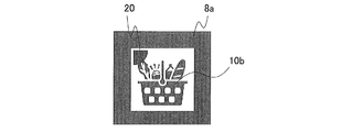
- FIG. 7 is a front view showing a state in which there is a first layer of display means for displaying an icon for selecting a function to be set by contact by the user of the operating device according to the first embodiment.
- the light emitted from the light source of the second light source 19 is transmitted through the transmission part of the second layer 8b, whereby the mark 20 appears on the first layer 8a.
- the control means (not shown) turns on the second light source 19 when the function corresponding to the icon 10b is set when the first light source 15 is turned on to display the icon 10b. Further, the control means (not shown) does not turn on the second light source 19 when the function setting is cancelled.
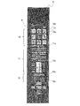
- FIG. 8 is a diagram illustrating a state in which all display elements of the operating device according to the first embodiment are displayed, with the first light source overlapped.
- the surface component 8 is provided with a function selection section 10, a function explanation section 11, and a function setting section 12 in a vertical row, and the first light source 15 is in a direction perpendicular to the column direction. In this example, light is emitted to the light guide plate 16 from the left-right direction.
- the first light source 15 emits light to the light guide plate 16 from the vertical direction.
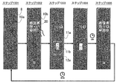
- FIG. 9 is a diagram illustrating an example of a change in the display state of the display element when the function of the controller device according to the first embodiment is selected and set.
- Step 901 is a state before the operation.
- the control means (not shown) always lights up the first light source 15 provided on the icon 10a so that the icon 10a is always visible.
- Control means (not shown) turns off the first light source 15 provided in the display element 9 other than the icon 10a so that it cannot be visually recognized. By operating in this manner, power consumption during standby can be suppressed.
- the process proceeds to step 902.
- step 902 the control means (not shown) turns on all the first light sources 15 provided in the icons 10b other than the icon 10a in the function selection section 10, and makes all the icons 10b visible.
- the process proceeds to step 903.
- step 903 the control means (not shown) turns on the first light source 15 provided in the word 11a corresponding to the selected icon 10b so that the word 11a is visible.
- the control means (not shown) is displayed so that the area of the symbol 11b corresponding to the room where the function corresponding to the selected icon 10b acts is bright and the area of the symbol 11b corresponding to the other room is dark.
- Z controls the luminance of the first light source 15.
- the first light source 15 provided on the icon 12a is turned on to make the icon 12a visible.
- the process proceeds to step 904.
- the step of confirming whether or not to set after selecting the icon 10b is provided, so that the user can determine whether or not to set the function while operating.
- FIG. 9 shows a case where the control means (not shown) turns off the first light source 15 provided in the icon 10b other than the selected icon 10b.
- the present invention is not limited to such a case.
- the first light source 15 provided in the icon 10b other than the selected icon 10b may remain turned on.
- the control means controls the luminance of the first light source 15 so that the area of the pattern 11b corresponding to the room other than the room where the function corresponding to the selected icon 10b acts is displayed darkly.
- the present invention is not limited to such a case.
- the first light source 15 is controlled so that the area of the symbol 11b corresponding to the room other than the room where the function corresponding to the selected icon 10b operates is not displayed. May be.
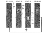
- step 904 the control means (not shown) turns on the first light source 15 provided in the wording 12b to make the wording 12b visible.
- the control means (not shown) maintains the state for a predetermined time (for example, 5 seconds), and proceeds to step 905.
- the control means (not shown) controls the luminance of the first light source 15 so that the entire area of the symbol 11b is displayed brightly.
- the brightness of the first light source 15 may be controlled so that the pattern 11b maintains the state of step 903. Moreover, you may control the brightness
- step 905 the control means (not shown) turns on the first light source 15 and the second light source 19 provided on the icon 10b corresponding to the set function so that the icon 10b and the mark 20 can be visually recognized.
- a predetermined time for example, 30 seconds
- the process returns to step 901.
- FIG. 9 shows a case where the control means (not shown) turns on the first light sources 15 provided in all the icons 10b.
- the function is set.
- the first light source 15 provided on the icon 10b other than the icon 10b may be turned off.
- the order in which the function selection section 10, the function explanation section 11, and the function setting section 12 are arranged may be changed as appropriate. Further, the function selection section 10, the function explanation section 11, and the function setting section 12 may not be arranged continuously. As described above, when the function selection section 10, the function explanation section 11, and the function setting section 12 are sequentially arranged, the sections are arranged in the order that the user visually recognizes the operation. The user can operate while confirming the content of the function in a natural flow. Further, the user does not hesitate which display element 9 the user should contact next, and does not feel stress.
- FIG. 10 is a diagram illustrating an example of a change in the display state of the display element when the function of the controller device according to the first embodiment is selected and the setting is canceled.
- the process proceeds to step 1002.
- step 1002 the control means (not shown) lights the second light source 19 provided in the icon 10b for which the function is set, in addition to the first light source 15 provided in all the icons 10b.
- the process proceeds to step 1003.
- step 1003 similarly to step 903, the control means (not shown) turns on the first light source 15 provided in the word 11a corresponding to the selected icon 10b to make the word 11a visible.
- the control means turns on the first light source 15 provided in the word 11a corresponding to the selected icon 10b to make the word 11a visible.
- all the first light sources 15 provided in the symbol 11b are turned on.
- the first light source 15 provided on the icon 12a is turned on to make the icon 12a visible.
- step 1004. If the user touches the icon 12 a marked “Yes”, the process proceeds to step 904.
- step 1004 the control means (not shown) turns off the second light source 19 provided in the icon 10b whose function has been canceled.
- the control means (not shown) maintains the state for a predetermined time (for example, 5 seconds), and proceeds to step 1005.
- FIG. 10 shows a case where the control means (not shown) does not turn on the first light source 15 provided in the wording 12b.
- the present invention is not limited to such a case.
- the phrase “setting has been released” is written, the first light source 15 provided in the sentence 12b may be turned on so that the phrase “setting has been released” may be visible.
- step 1005 the control means (not shown) turns on the first light sources 15 provided in all the icons 10b so that all the icons 10b are visible.
- a predetermined time for example, 30 seconds
- FIG. 11 is a diagram illustrating an example of a change in the display state of the display element when setting or canceling the function of the controller device according to the first embodiment is stopped halfway.
- releasing a setting it simplified or abbreviate
- step 1101 when the user touches the icon 10a, the process proceeds to step 1102.
- step 1102 when the user touches the icon 10b whose function is to be set or canceled, the process proceeds to step 1103.
- FIG. 11 shows a case where the user touches the icon 10b whose function is to be canceled.
- step 1103 the control means (not shown) controls the first light source 15 and the second light source 19 as in step 903 or step 1003.
- the user touches the icon 10a when he / she wants to stop setting or canceling the function, for example, by visually recognizing the word 11a or the symbol 11b and noticing an error in selecting the function.
- the control means recognizes contact with the icon 10a, the control means proceeds to step 1104.
- step 1104 the control means (not shown) returns the display state of the display element 9 to the display state of step 1102. If a predetermined time (for example, 30 seconds) has passed without the user subsequently touching any display element 9, the process returns to step 1101.
- a predetermined time for example, 30 seconds
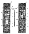
- FIG. 12 is a diagram illustrating a state in which the user of the operation device according to Comparative Example 1 visually recognizes the display element from the front.
- FIG. 13 is a diagram illustrating a display state of display elements when the first light source of the operating device according to Comparative Example 1 is turned on. As shown in FIG. 12, the operating device according to Comparative Example 1 is provided with the first light source 15 so that the optical axis is perpendicular to the surface of the surface component 8.
- the user visually recognizes the display element 9 from the front, the user's line of sight faces the optical axis of the first light source 15, and the spherical appearance of the light emitting part of the first light source 15 as shown in FIG. As a result, it is difficult for the user to read the display element 9.
- FIG. 14 is a diagram illustrating a state in which the user of the operation device according to Comparative Example 2 visually recognizes the display element displayed above from below.
- FIG. 15 is a diagram illustrating a state in which the user of the operation device according to Comparative Example 2 visually recognizes the display element displayed below from above.
- the operation device according to Comparative Example 2 is provided with the first light source 15 so that the optical axis is parallel to the surface of the surface component 8. Therefore, when the user visually recognizes the display element 9 from the front, the user's line of sight does not face the optical axis of the first light source 15, and the spherical appearance phenomenon as shown in FIG.
- the first light source 15 of the display element 9 provided above is provided on the upper side of the light guide plate 16, or the first light source of the display element 9 provided below. 15 is provided on the lower side of the light guide plate 16, the light emitted from the first light source 15 has a spread angle around the optical axis, so that the user's line of sight is widened. Will face each other.
- the spherical appearance phenomenon as shown in FIG. 13 is alleviated, the light emitting portion of the first light source 15 still enters the user's field of view, and it is difficult for the user to read the display element 9. was there.
- FIG. 16 is a diagram illustrating a visual recognition order of the user of the operation device according to the first embodiment.
- FIG. 16 shows both the case where the word 11a is displayed above the symbol 11b and the case where the symbol 11b is displayed above the word 11a.
- the function selection section 10, the function explanation section 11, and the function setting section 12 are provided in a line according to the visual recognition order of the user. That is, when setting a function, the user moves his / her eyes in the order of the function selection section 10, the function explanation section 11, and the function setting section 12.
- the function explanation section 11 is provided at a height that substantially matches the height of the line of sight when a user of standard height stands upright. Therefore, the user's line of sight when viewing the function selection section 10 is upward, and the user's line of sight when viewing the function setting section 12 is downward. By being configured in this way, the user can visually recognize the word 11a and the symbol 11b displayed in the function explanation section 11 from substantially the front, and can confirm the explanation of the function in an easy posture. Further, the approximate center in the height direction of the three sections and the height of the line of sight when the user stands upright and substantially in front view substantially match, and the vertical movement of the line of sight can be made substantially equal in the vertical direction.
- the standard height here means the average height of women (average value excluding 5% of the height of women in their 20s and 60s). is there. For this reason, in the case of Japan, for example, the height of the function explanation section 11 from the installation surface is approximately 130 to approximately equal to the height of the line of sight when a standard height user looks upright. It should be 150 cm.
- the optical axis is parallel to the surface of the surface component 8 and is partitioned as shown in FIG.
- the first light source 15 is arranged in a direction perpendicular to the column direction of the first row, in this example, in the left-right direction.
- the user's line of sight does not face the optical axis of the first light source 15, and the spherical appearance phenomenon shown in FIGS. 12 and 13 can be prevented. Is difficult to read.
- the three sections are graphics that include the three sections and the figure having the minimum perimeter is drawn, the width dimension in the horizontal direction is smaller than the width dimension in the vertical direction.
- the optical axis of the first light source 15 is provided in a direction substantially perpendicular to the vertical direction in this way, so that the light emitting portion of the first light source 15 can easily enter the visual field of the user in FIG. 15 can be prevented, and as a result, the frequency with which the light emitting portion of the first light source 15 enters the user's field of view is reduced, and the display element 9 is difficult to read. Improved.
- the operation device is such that, for example, the user has a relative relationship between the position of the function explanation section 11 and the position of the line of sight when viewed by the user, such as a low-height device or a portable device.
- the user can place the function selection section 10, the function explanation section 11, and the function setting section 12 in a centrally arranged section, That is, in this example, the standing position and posture are changed so that the function explanation section 11 is viewed from the front. Therefore, even if the function explanation section 11 is not provided at a height that substantially matches the height of the line of sight when a user with standard height stands upright, the user selects the function selection section 10.
- the direction of the line of sight is changed so that it is upward when viewing and downward when viewing the function setting section 12, and the optical axis of the first light source 15 is provided in a direction substantially perpendicular to the vertical direction. Similarly to the above, it is possible to prevent a spherical appearance phenomenon as shown in FIGS. 14 and 15 with respect to movement in the vertical direction.
- each section when each section is provided in a horizontal row, the user changes the standing position and posture so that the section arranged in the center is viewed from the front. For this reason, the user changes the direction of the line of sight so that the right side section is turned to the right and the left side section is turned to the left, and the optical axis of the first light source 15 is changed to the left and right direction.
- the user By providing in a substantially vertical direction, it is possible to prevent the phenomenon of spherical appearance as shown in FIGS.
- each section when each section is provided at a height that approximately matches the height of the line of sight when a normal height user stands upright, the user can position each section in a comfortable posture. Visual recognition is possible.
- the first light sources 15 of all the display elements 9 are arranged in the left-right direction, but only the first light sources 15 of some display elements 9 are arranged in the left-right direction. May be.
- the frequency of the spherical appearance phenomenon can be further reduced.
- step 902 in FIG. 9, step 1002 in FIG. 10, step 1102 in FIG. 11, and the like control means (not shown) is provided for all the icons 10b in the function selection section 10.
- the first light source 15 is turned on, the present invention is not limited to such a case.
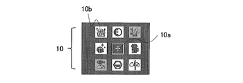
- 17 and 18 are diagrams showing a modification of the display state of the function selection section of the operating device according to the first embodiment. For example, as shown in FIG. 17, when there is a function that cannot be set depending on the operating state of the refrigerator-freezer, the first light source 15 provided on the icon 10b corresponding to the function that cannot be set may be turned off. With this configuration, the user can recognize which function cannot be set. Also, as shown in FIG.
- the first light source 15 provided on the icon 10b corresponding to the function that cannot be set is turned off, there is a possibility that some users may erroneously recognize that the first light source 15 has failed. Therefore, as shown in FIG. 18, the first light source 15 provided in the icon 10b corresponding to the function that cannot be set may be lit darkly. With this configuration, it is possible to distinguish and visually recognize the icon 10b corresponding to the function that can be set by the user and the icon 10b corresponding to the function that cannot be set.
- FIG. 19 is a diagram illustrating a modification of the function setting section of the controller device according to the first embodiment.
- the icon 12a may be displayed above the wording 12b.
- the word 12b is displayed when the user touches the icon 12a, the word 12b is hidden by the hand touching the icon 12a, and the function is set. The user cannot recognize.
- the icon 12a is displayed below the wording 12b as shown in FIG. 2, the wording 12b is not hidden by the hand, and the user is more sure that the function has been set. It becomes possible to recognize.
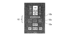
- FIG. 20 is a diagram illustrating a modification of the icon for canceling the setting or canceling of the function of the controller device according to the first embodiment.
- an icon 12c may be added exclusively for it.
- the icon 12c is provided with display means 13 having input means 18. Symbols (characters) such as “return” and “cancel” are written on the icon 12c.
- characters such as “return” and “cancel” are written on the icon 12c.
- the first layer 8a and the second layer 8b are provided on the surface of the permeable member 8c.
- a layer may be provided in addition to the surface of the permeable member 8c.
- other layers or other members may be provided on the surface side of the first layer 8a.
- the first layer 8a and the second layer 8b may be provided on a member different from the permeable member 8c, and the different member may be provided on the front surface side or the back surface side of the surface component 8. In that case, the surface component 8 and its different members may be integrated.
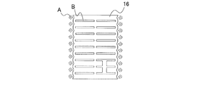
- the light guide plate 16 is provided for each display element 9, but each light guide plate 16 may be integrated. With this configuration, it is not necessary to attach the light guide plates 16 individually, and the assembling work becomes easier. For example, all the light guide plates 16 may be integrated into one component, or may be integrated for each section or each form of the display element 9.
- FIG. 21 is a diagram illustrating an example when the light guide plate of the operating device according to the first embodiment is integrated. For example, when the light guide plate 16 provided in the wording 11a is integrated, the shape shown in FIG.
- the 1st light source 15 is arrange
- the shielding wall 17 is arrange
- the input unit 18 is composed of electrodes of a capacitive touch sensor incorporated in the display unit 13.
- the input unit 18 may be configured by a switch such as a button, and the switch may be provided in the vicinity of the display unit 13 in the vertical and horizontal directions or in another casing that can communicate with the operation device 7. Good.
- the switch when the input unit 18 is configured by an electrode of a capacitive touch sensor incorporated in the display unit 13 as in the operation device according to the first embodiment, it is durable. It becomes possible to improve the property.
- unlike a switch it does not have a groove into which moisture or the like enters, so that water resistance can be improved.
- static electricity does not accumulate in the grooves into which moisture enters, and the user does not feel stress during operation.
- FIG. 22 is a diagram illustrating a state in which all display elements of the controller device according to the second embodiment are displayed, with the first light source overlapped. As shown in FIG.
- the surface part 8 is provided with a function selection section 10, a function explanation section 11, and a function setting section 12 in a vertical row, and the first light source 15 is arranged in a direction parallel to the column direction. In the example, light is emitted from the vertical direction to the light guide plate 16.
- the display element 9 above the approximate center in the height direction of the function explanation section 11, in this example, the icon 10 a, the icon 10 b, and the first light source 15 provided in the wording 11 a are arranged below the light guide plate 16. . Further, the display element 9 below the approximate center in the height direction of the function explanation section 11, in this example, the first light source 15 provided in the symbol 11 b, the icon 12 a, and the wording 12 b is disposed above the light guide plate 16. Is done. When each section is provided in a horizontal row, the first light source 15 provided in the display element 9 on the right side from the substantially horizontal center of the function explanation section 11 is disposed on the left side of the light guide plate 16. Is done. Further, the first light source 15 provided in the display element 9 on the left side from the approximate center in the horizontal direction of the function explanation section 11 is disposed on the right side of the light guide plate 16.
- the function explanation section 11 is provided so that the height of the approximate center in the height direction substantially coincides with the height of the line of sight when a standard height user stands upright. Therefore, in this example, the user's eyes when visually recognizing the icon 10a, the icon 10b, and the wording 11a are upward, and the user's eyes when visually recognizing the symbol 11b, the icon 12a, and the wording 12b are downward.
- FIG. 23 is a diagram illustrating a state in which the user of the operation device according to the second embodiment visually recognizes the display element displayed above from below.
- FIG. 24 is a diagram illustrating a state in which the user of the operating device according to the second embodiment visually recognizes the display element displayed below from above.
- the first light source 15 is guided in the display element 9 displayed above. Since the display element 9 displayed below and below the light plate 16 is disposed above the light guide plate 16, as shown in FIGS.
- the height of the standard height is approximately the center in the height direction, that is, the height of the region between the region where the word 11a is displayed and the region where the symbol 11b is displayed.
- the function explanation section 11 is provided so as to substantially coincide with the height of the line of sight when the person stands upright and viewed from the front.
- the height of the line of sight when a user who is not standard height stands upright is the area between the area where the word 11a is displayed and the area where the pattern 11b is displayed. It matches the height of the part other than the area between.
- the operation device allows the user to freely determine the relative relationship between the position of the function explanation section 11 and the position of the line of sight when viewed by the user, such as a low-height device or a portable device.
- a low-height device or a portable device When mounted on a device that can be changed, it is not necessary to consider variations in the height of the user.
- the height of the function explanation section 11 is approximately the same as the height in the height direction and the height of the line of sight when the user stands upright.
- the display elements 9 other than the display element 9 displayed between the parts since the phenomenon of spherical appearance as shown in FIGS. 14 and 15 is prevented, the display element 9 is not difficult to read.
- the height of the approximate center in the height direction of the function explanation section 11 is substantially matched with the height of the line of sight when a standard height user stands upright.
- the height of the other part of the surface component 8 may be substantially matched with the height of the line of sight when the user of standard height stands upright.
- the first light source 15 provided on the display element 9 above the height portion approximately equal to the height of the line of sight when a user with standard height stands upright and viewed from the front is the light guide plate.
- the first display element 9 is disposed below the display element 9 and is located below a portion having a height substantially coincident with the height of the line of sight when a user of standard height stands upright.
- the light source 15 may be disposed on the upper side of the light guide plate 16.
- the height of the approximate center in the height direction of the function explanation section 11 is made to substantially coincide with the height of the line of sight when a standard height user stands upright.
- the vertical movement of the line of sight can be made substantially equal in the vertical direction.
- the first light sources 15 of all the display elements 9 displayed above are the first of all the display elements 9 displayed below and below the light guide plate 16.
- the light source 15 is arranged on the upper side of the light guide plate 16, only the first light sources 15 of some display elements 9 may be arranged as such.
- the frequency of the spherical appearance phenomenon can be further reduced.
- FIG. 25 is a diagram illustrating a state in which all display elements of the operating device according to the third embodiment are displayed, with the first light source overlapped.
- the surface component 8 is provided with a function selection section 10, a function explanation section 11, and a function setting section 12 in a vertical line.
- the display elements 9 displayed in the function selection section 10 and the function setting section 12, in this example, the first light source 15 provided in the icon 10a, the icon 10b, the icon 12a, and the wording 12b are parallel to the column direction of the section. Light is emitted to the light guide plate 16 from the direction, that is, the vertical direction.
- each division is provided in a horizontal line, light is radiate
- the display element 9 displayed in the function selection section 10, in this example, the first light source 15 provided in the icon 10 a and the icon 10 b is arranged below the light guide plate 16. Further, the display element 9 displayed in the function setting section 12, in this example, the first light source 15 provided in the icon 12 a and the wording 12 b is arranged on the upper side of the light guide plate 16. When each section is provided in a horizontal row, the first light source 15 provided in the display element 9 displayed in the section on the right side of the function explanation section 11 is disposed on the left side of the light guide plate 16. The Further, the first light source 15 provided in the display element 9 displayed in the section on the left side of the function explanation section 11 is disposed on the right side of the light guide plate 16.
- the function explanation section 11 is provided at a height substantially coincident with the height of the line of sight when a user with standard height stands upright and the line of sight of the user when viewing the function selection section 10 is upward. The user's eyes when viewing the function setting section 12 are downward.
- the optical axis of the first light source 15 and the user's line of sight face each other. Since the spherical appearance phenomenon as shown in FIG. 13 does not occur, the reading difficulty of the display element 9 is improved.
- the operation device according to the third embodiment has the first light source in the user's field of view when the user's line of sight moves. Since the frequency of occurrence of the sphere appearance phenomenon as shown in FIG. 14 and FIG. 15 is reduced because the 15 light emitting portions are included, the reading difficulty of the display element 9 is improved.
- the first light source 15 provided in the display element 9 displayed in the function selection section 10 and the function setting section 12 emits light to the light guide plate 16 from the vertical direction.
- the frequency of the sphere appearance phenomenon when the display element 9 displayed in the function selection section 10 and the function setting section 12 is visually recognized can be further reduced.
- the first light source 15 provided in the display element 9 displayed in the function explanation section 11 emits light to the light guide plate 16 from the left and right directions. It is not necessary to consider variations in the height of the user, such as providing a space between the area where the word 11a is displayed and the area where the symbol 11b is displayed, as in the operation device according to the above.
- the first light source 15 provided in the display element 9 displayed in the function explanation section 11 emits light to the light guide plate 16 from the left and right directions. Since the first light source 15 does not need to be provided between the display elements 9 of the words 11a and the symbols 11b displayed in the function explanation section 11 as in the operation device according to the above, the display elements 9 of the words 11a and the symbols 11b are displayed. Can be arranged at narrower intervals, and the operating device 7 can be reduced in size.
- FIG. 26 is a diagram illustrating a state in which all display elements of the operating device according to the third embodiment are displayed, with the first light source overlapped.
- the first light source 15 provided in the wording 12b displayed in the function setting section 12 emits light to the light guide plate 16 from a direction parallel to the column direction of the section, that is, from the vertical direction.
- light may be emitted to the light guide plate 16 from a direction perpendicular to the column direction of the sections, that is, from the left and right directions.
- the optical axis direction of the first light source 15 provided in the horizontally long display element 9 matches the longitudinal direction of the display element 9, and the display element 9 is made more uniform with a small number of first light sources 15. Can be displayed.
- the first light sources 15 of all the display elements 9 displayed in the function explanation section 11 are all displayed in the left-right direction of the light guide plate 16 and in the function selection section 10.
- the first light sources 15 of the display elements 9 are arranged below the light guide plate 16 and the first light sources 15 of all the display elements 9 displayed in the function setting section 12 are arranged above the light guide plate 16. Only the first light source 15 of the display element 9 may be arranged as such. When the first light sources 15 of all the display elements 9 are arranged in such a manner, the frequency of the spherical appearance phenomenon can be further reduced.
- Embodiment 4 FIG.
- the operating device according to the fourth embodiment is different from the operating device according to the first to third embodiments in the structure of surface parts and display means.
- the structure of the surface component and the display means of the operating device according to the fourth embodiment will be described.
- or Embodiment 3 is simplified or abbreviate
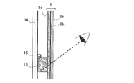
- the structure of the display means for displaying the surface components of the operating device according to the fourth embodiment and the display elements not having the function as the input means will be described with reference to FIG. FIG.
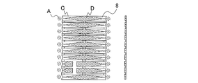
- FIG. 27 is a diagram illustrating a cross-sectional structure of a display unit that displays surface components of the operating device according to the fourth embodiment and display elements that do not have a function as an input unit. As shown in FIG. 27, the display means 13 is provided between the surface component 8 and the printed board 14.
- the display means 13 includes a first light source 15 and a shielding wall 17.
- a convex portion C is formed in a region where the display element is written on the transparent member 8 c of the surface component 8, and the convex portion C projects between the shielding walls 17.
- a diffuse pattern D is formed on the surface of the transmissive member 8c facing the printed circuit board 14.
- the diffuse pattern D may be formed on a member different from the transparent member 8c, and the different member may be provided on the back side of the front surface component 8 (the different member on which the diffuse pattern D is formed is This corresponds to the “light emitting member” in the invention). In that case, the surface component 8 and its different members may be integrated.
- FIG. 28 is a diagram illustrating a cross-sectional structure of a display unit that displays a surface element of a controller device according to Embodiment 4 and a display element having a function as an input unit.
- the display unit 13 includes a first light source 15, a shielding wall 17, and an input unit 18.
- the input means 18 is an electrode of a capacitive touch sensor.
- the input means 18 is attached to the surface of the printed circuit board 14.
- the input means 18 is provided on the back side of the diffuse pattern D.
- the input means 18 detects that the capacitance value changes via the surface component 8 when the user touches the area where the display element 9 of the surface component 8 is displayed, and controls the control means (not shown). ) Signal.
- FIG. 29 is a diagram illustrating an example of a surface part of the operating device according to the fourth embodiment.
- the surface component 8 may be shaped as shown in FIG.
- the 1st light source 15 is arrange
- the shielding wall 17 is provided between the convex portions C.
- a diffuse pattern D is formed on the back surface of the surface component 8.
- the diffuse pattern D is formed so that the pattern density increases as the distance from the first light source 15 increases. With this configuration, the display state of the display element 9 can be made more uniform.
- the light scattering pattern D is formed on the surface component 8.
- the light guide plate 16 is provided on the back surface side of the surface component 8.
- the light scattering pattern D may be formed on the light guide plate 16.
- or Embodiment 4 was demonstrated, this invention is not limited to description of each embodiment. For example, it is possible to combine each embodiment and each modification.
- Refrigerated freezer 2 refrigerated room, 2a, 2b door, 3 ice making room, 4 temperature switching room, 5 freezer room, 6 vegetable room, 7 operating device, 8 surface parts, 8a 1st layer, 8b 2nd layer, 8c permeation Member, 9 display element, 10 function selection section, 10a icon, 10b icon, 11 function explanation section, 11a wording, 11b symbol, 12 function setting section, 12a icon, 12b wording, 12c icon, 13 display means, 14 Printed circuit board, 15 1st light source, 16 light guide plate, 17 shielding wall, 18 input means, 19 2nd light source, 20 mark, A area, B groove or hole, C convex part, D diffuse pattern.
Abstract
Priority Applications (2)
| Application Number | Priority Date | Filing Date | Title |
|---|---|---|---|
| SG11201500016UA SG11201500016UA (en) | 2012-08-09 | 2013-07-11 | Operation device and refrigerator/freezer |
| AU2013300820A AU2013300820B2 (en) | 2012-08-09 | 2013-07-11 | Operation device and refrigerator-freezer |
Applications Claiming Priority (2)
| Application Number | Priority Date | Filing Date | Title |
|---|---|---|---|
| JP2012-176700 | 2012-08-09 | ||
| JP2012176700A JP5881554B2 (ja) | 2012-08-09 | 2012-08-09 | 操作装置及び冷凍冷蔵庫 |
Publications (1)
| Publication Number | Publication Date |
|---|---|
| WO2014024631A1 true WO2014024631A1 (fr) | 2014-02-13 |
Family
ID=50047366
Family Applications (1)
| Application Number | Title | Priority Date | Filing Date |
|---|---|---|---|
| PCT/JP2013/069048 WO2014024631A1 (fr) | 2012-08-09 | 2013-07-11 | Dispositif d'actionnement et réfrigérateur/congélateur |
Country Status (7)
| Country | Link |
|---|---|
| JP (1) | JP5881554B2 (fr) |
| CN (2) | CN103575055B (fr) |
| AU (1) | AU2013300820B2 (fr) |
| HK (1) | HK1191087A1 (fr) |
| SG (1) | SG11201500016UA (fr) |
| TW (1) | TWI528007B (fr) |
| WO (1) | WO2014024631A1 (fr) |
Families Citing this family (4)
| Publication number | Priority date | Publication date | Assignee | Title |
|---|---|---|---|---|
| JP5881554B2 (ja) * | 2012-08-09 | 2016-03-09 | 三菱電機株式会社 | 操作装置及び冷凍冷蔵庫 |
| JP2015203525A (ja) * | 2014-04-14 | 2015-11-16 | 株式会社東芝 | 冷蔵庫 |
| JP6198682B2 (ja) * | 2014-06-24 | 2017-09-20 | 三菱電機株式会社 | 冷蔵庫 |
| JP2018013304A (ja) * | 2016-07-22 | 2018-01-25 | 日立アプライアンス株式会社 | 表示装置およびそれを備えた冷蔵庫 |
Citations (4)
| Publication number | Priority date | Publication date | Assignee | Title |
|---|---|---|---|---|
| JP2004227997A (ja) * | 2003-01-24 | 2004-08-12 | Alps Electric Co Ltd | 照光式タッチパネル |
| WO2010073653A1 (fr) * | 2008-12-24 | 2010-07-01 | パナソニック株式会社 | Réfrigérateur |
| JP2010230226A (ja) * | 2009-03-26 | 2010-10-14 | Haier Sanyo Electric Co Ltd | 温度表示器及び温度表示器を備えた冷却貯蔵庫 |
| JP2012059612A (ja) * | 2010-09-10 | 2012-03-22 | Dainippon Printing Co Ltd | 面発光装置 |
Family Cites Families (2)
| Publication number | Priority date | Publication date | Assignee | Title |
|---|---|---|---|---|
| JP5127794B2 (ja) * | 2009-08-26 | 2013-01-23 | 三菱電機株式会社 | 冷蔵庫 |
| JP5881554B2 (ja) * | 2012-08-09 | 2016-03-09 | 三菱電機株式会社 | 操作装置及び冷凍冷蔵庫 |
-
2012
- 2012-08-09 JP JP2012176700A patent/JP5881554B2/ja not_active Expired - Fee Related
-
2013
- 2013-07-11 SG SG11201500016UA patent/SG11201500016UA/en unknown
- 2013-07-11 AU AU2013300820A patent/AU2013300820B2/en active Active
- 2013-07-11 WO PCT/JP2013/069048 patent/WO2014024631A1/fr active Application Filing
- 2013-07-23 TW TW102126216A patent/TWI528007B/zh active
- 2013-08-09 CN CN201310345441.0A patent/CN103575055B/zh active Active
- 2013-08-09 CN CN201320484743.1U patent/CN203629199U/zh not_active Withdrawn - After Issue
-
2014
- 2014-04-28 HK HK14104056.7A patent/HK1191087A1/xx unknown
Patent Citations (4)
| Publication number | Priority date | Publication date | Assignee | Title |
|---|---|---|---|---|
| JP2004227997A (ja) * | 2003-01-24 | 2004-08-12 | Alps Electric Co Ltd | 照光式タッチパネル |
| WO2010073653A1 (fr) * | 2008-12-24 | 2010-07-01 | パナソニック株式会社 | Réfrigérateur |
| JP2010230226A (ja) * | 2009-03-26 | 2010-10-14 | Haier Sanyo Electric Co Ltd | 温度表示器及び温度表示器を備えた冷却貯蔵庫 |
| JP2012059612A (ja) * | 2010-09-10 | 2012-03-22 | Dainippon Printing Co Ltd | 面発光装置 |
Also Published As
| Publication number | Publication date |
|---|---|
| AU2013300820B2 (en) | 2016-01-28 |
| CN103575055A (zh) | 2014-02-12 |
| JP5881554B2 (ja) | 2016-03-09 |
| AU2013300820A1 (en) | 2015-02-05 |
| HK1191087A1 (en) | 2014-07-18 |
| CN103575055B (zh) | 2015-10-28 |
| JP2014035138A (ja) | 2014-02-24 |
| SG11201500016UA (en) | 2015-02-27 |
| TW201413200A (zh) | 2014-04-01 |
| CN203629199U (zh) | 2014-06-04 |
| TWI528007B (zh) | 2016-04-01 |
Similar Documents
| Publication | Publication Date | Title |
|---|---|---|
| KR102011019B1 (ko) | 냉장고 | |
| JP5897932B2 (ja) | 冷蔵庫 | |
| JP5667805B2 (ja) | 冷蔵庫 | |
| JP5881554B2 (ja) | 操作装置及び冷凍冷蔵庫 | |
| JP5773948B2 (ja) | 冷蔵庫 | |
| AU2015282309B2 (en) | Refrigerator | |
| TWI570376B (zh) | 冰箱 | |
| JP5858880B2 (ja) | 冷蔵庫及び操作装置 | |
| TW201418652A (zh) | 冰箱 | |
| JP2011047550A (ja) | 冷蔵庫 | |
| US20100225499A1 (en) | Device for inputting control commands | |
| KR101883320B1 (ko) | 냉장고 | |
| JP2016102603A (ja) | 冷蔵庫 | |
| JP2016038137A (ja) | 冷蔵庫 | |
| JP2018077044A (ja) | 冷蔵庫 | |
| KR100993054B1 (ko) | 냉장고 | |
| CN102706090A (zh) | 用于冰箱的触控装置及具有其的冰箱 | |
| CN202599009U (zh) | 用于冰箱的触控装置及具有其的冰箱 |
Legal Events
| Date | Code | Title | Description |
|---|---|---|---|
| 121 | Ep: the epo has been informed by wipo that ep was designated in this application |
Ref document number: 13827667 Country of ref document: EP Kind code of ref document: A1 |
|
| ENP | Entry into the national phase |
Ref document number: 2013300820 Country of ref document: AU Date of ref document: 20130711 Kind code of ref document: A |
|
| NENP | Non-entry into the national phase |
Ref country code: DE |
|
| 122 | Ep: pct application non-entry in european phase |
Ref document number: 13827667 Country of ref document: EP Kind code of ref document: A1 |