WO2014021148A1 - バッテリー交換ロボットの教示方法およびバッテリー交換ロボット - Google Patents
バッテリー交換ロボットの教示方法およびバッテリー交換ロボット Download PDFInfo
- Publication number
- WO2014021148A1 WO2014021148A1 PCT/JP2013/069966 JP2013069966W WO2014021148A1 WO 2014021148 A1 WO2014021148 A1 WO 2014021148A1 JP 2013069966 W JP2013069966 W JP 2013069966W WO 2014021148 A1 WO2014021148 A1 WO 2014021148A1
- Authority
- WO
- WIPO (PCT)
- Prior art keywords
- battery
- detection
- robot
- vehicle
- control unit
- Prior art date
- Legal status (The legal status is an assumption and is not a legal conclusion. Google has not performed a legal analysis and makes no representation as to the accuracy of the status listed.)
- Ceased
Links
Images















Classifications
-
- B—PERFORMING OPERATIONS; TRANSPORTING
- B60—VEHICLES IN GENERAL
- B60S—SERVICING, CLEANING, REPAIRING, SUPPORTING, LIFTING, OR MANOEUVRING OF VEHICLES, NOT OTHERWISE PROVIDED FOR
- B60S5/00—Servicing, maintaining, repairing, or refitting of vehicles
-
- B—PERFORMING OPERATIONS; TRANSPORTING
- B60—VEHICLES IN GENERAL
- B60L—PROPULSION OF ELECTRICALLY-PROPELLED VEHICLES; SUPPLYING ELECTRIC POWER FOR AUXILIARY EQUIPMENT OF ELECTRICALLY-PROPELLED VEHICLES; ELECTRODYNAMIC BRAKE SYSTEMS FOR VEHICLES IN GENERAL; MAGNETIC SUSPENSION OR LEVITATION FOR VEHICLES; MONITORING OPERATING VARIABLES OF ELECTRICALLY-PROPELLED VEHICLES; ELECTRIC SAFETY DEVICES FOR ELECTRICALLY-PROPELLED VEHICLES
- B60L50/00—Electric propulsion with power supplied within the vehicle
- B60L50/50—Electric propulsion with power supplied within the vehicle using propulsion power supplied by batteries or fuel cells
- B60L50/60—Electric propulsion with power supplied within the vehicle using propulsion power supplied by batteries or fuel cells using power supplied by batteries
- B60L50/66—Arrangements of batteries
-
- B—PERFORMING OPERATIONS; TRANSPORTING
- B25—HAND TOOLS; PORTABLE POWER-DRIVEN TOOLS; MANIPULATORS
- B25J—MANIPULATORS; CHAMBERS PROVIDED WITH MANIPULATION DEVICES
- B25J9/00—Program-controlled manipulators
- B25J9/16—Program controls
-
- B—PERFORMING OPERATIONS; TRANSPORTING
- B60—VEHICLES IN GENERAL
- B60L—PROPULSION OF ELECTRICALLY-PROPELLED VEHICLES; SUPPLYING ELECTRIC POWER FOR AUXILIARY EQUIPMENT OF ELECTRICALLY-PROPELLED VEHICLES; ELECTRODYNAMIC BRAKE SYSTEMS FOR VEHICLES IN GENERAL; MAGNETIC SUSPENSION OR LEVITATION FOR VEHICLES; MONITORING OPERATING VARIABLES OF ELECTRICALLY-PROPELLED VEHICLES; ELECTRIC SAFETY DEVICES FOR ELECTRICALLY-PROPELLED VEHICLES
- B60L50/00—Electric propulsion with power supplied within the vehicle
- B60L50/50—Electric propulsion with power supplied within the vehicle using propulsion power supplied by batteries or fuel cells
-
- B—PERFORMING OPERATIONS; TRANSPORTING
- B60—VEHICLES IN GENERAL
- B60L—PROPULSION OF ELECTRICALLY-PROPELLED VEHICLES; SUPPLYING ELECTRIC POWER FOR AUXILIARY EQUIPMENT OF ELECTRICALLY-PROPELLED VEHICLES; ELECTRODYNAMIC BRAKE SYSTEMS FOR VEHICLES IN GENERAL; MAGNETIC SUSPENSION OR LEVITATION FOR VEHICLES; MONITORING OPERATING VARIABLES OF ELECTRICALLY-PROPELLED VEHICLES; ELECTRIC SAFETY DEVICES FOR ELECTRICALLY-PROPELLED VEHICLES
- B60L53/00—Methods of charging batteries, specially adapted for electric vehicles; Charging stations or on-board charging equipment therefor; Exchange of energy storage elements in electric vehicles
- B60L53/30—Constructional details of charging stations
-
- B—PERFORMING OPERATIONS; TRANSPORTING
- B60—VEHICLES IN GENERAL
- B60L—PROPULSION OF ELECTRICALLY-PROPELLED VEHICLES; SUPPLYING ELECTRIC POWER FOR AUXILIARY EQUIPMENT OF ELECTRICALLY-PROPELLED VEHICLES; ELECTRODYNAMIC BRAKE SYSTEMS FOR VEHICLES IN GENERAL; MAGNETIC SUSPENSION OR LEVITATION FOR VEHICLES; MONITORING OPERATING VARIABLES OF ELECTRICALLY-PROPELLED VEHICLES; ELECTRIC SAFETY DEVICES FOR ELECTRICALLY-PROPELLED VEHICLES
- B60L53/00—Methods of charging batteries, specially adapted for electric vehicles; Charging stations or on-board charging equipment therefor; Exchange of energy storage elements in electric vehicles
- B60L53/30—Constructional details of charging stations
- B60L53/35—Means for automatic or assisted adjustment of the relative position of charging devices and vehicles
-
- B—PERFORMING OPERATIONS; TRANSPORTING
- B60—VEHICLES IN GENERAL
- B60L—PROPULSION OF ELECTRICALLY-PROPELLED VEHICLES; SUPPLYING ELECTRIC POWER FOR AUXILIARY EQUIPMENT OF ELECTRICALLY-PROPELLED VEHICLES; ELECTRODYNAMIC BRAKE SYSTEMS FOR VEHICLES IN GENERAL; MAGNETIC SUSPENSION OR LEVITATION FOR VEHICLES; MONITORING OPERATING VARIABLES OF ELECTRICALLY-PROPELLED VEHICLES; ELECTRIC SAFETY DEVICES FOR ELECTRICALLY-PROPELLED VEHICLES
- B60L53/00—Methods of charging batteries, specially adapted for electric vehicles; Charging stations or on-board charging equipment therefor; Exchange of energy storage elements in electric vehicles
- B60L53/80—Exchanging energy storage elements, e.g. removable batteries
-
- B—PERFORMING OPERATIONS; TRANSPORTING
- B60—VEHICLES IN GENERAL
- B60L—PROPULSION OF ELECTRICALLY-PROPELLED VEHICLES; SUPPLYING ELECTRIC POWER FOR AUXILIARY EQUIPMENT OF ELECTRICALLY-PROPELLED VEHICLES; ELECTRODYNAMIC BRAKE SYSTEMS FOR VEHICLES IN GENERAL; MAGNETIC SUSPENSION OR LEVITATION FOR VEHICLES; MONITORING OPERATING VARIABLES OF ELECTRICALLY-PROPELLED VEHICLES; ELECTRIC SAFETY DEVICES FOR ELECTRICALLY-PROPELLED VEHICLES
- B60L58/00—Methods or circuit arrangements for monitoring or controlling batteries or fuel cells, specially adapted for electric vehicles
- B60L58/10—Methods or circuit arrangements for monitoring or controlling batteries or fuel cells, specially adapted for electric vehicles for monitoring or controlling batteries
- B60L58/18—Methods or circuit arrangements for monitoring or controlling batteries or fuel cells, specially adapted for electric vehicles for monitoring or controlling batteries of two or more battery modules
- B60L58/21—Methods or circuit arrangements for monitoring or controlling batteries or fuel cells, specially adapted for electric vehicles for monitoring or controlling batteries of two or more battery modules having the same nominal voltage
-
- H—ELECTRICITY
- H02—GENERATION; CONVERSION OR DISTRIBUTION OF ELECTRIC POWER
- H02J—ELECTRIC POWER NETWORKS; CIRCUIT ARRANGEMENTS OR SYSTEMS FOR SUPPLYING OR DISTRIBUTING ELECTRIC POWER; SYSTEMS FOR STORING ELECTRIC ENERGY
- H02J7/00—Circuit arrangements for charging or discharging batteries or for supplying loads from batteries
-
- B—PERFORMING OPERATIONS; TRANSPORTING
- B60—VEHICLES IN GENERAL
- B60L—PROPULSION OF ELECTRICALLY-PROPELLED VEHICLES; SUPPLYING ELECTRIC POWER FOR AUXILIARY EQUIPMENT OF ELECTRICALLY-PROPELLED VEHICLES; ELECTRODYNAMIC BRAKE SYSTEMS FOR VEHICLES IN GENERAL; MAGNETIC SUSPENSION OR LEVITATION FOR VEHICLES; MONITORING OPERATING VARIABLES OF ELECTRICALLY-PROPELLED VEHICLES; ELECTRIC SAFETY DEVICES FOR ELECTRICALLY-PROPELLED VEHICLES
- B60L2200/00—Type of vehicles
- B60L2200/18—Buses
-
- Y—GENERAL TAGGING OF NEW TECHNOLOGICAL DEVELOPMENTS; GENERAL TAGGING OF CROSS-SECTIONAL TECHNOLOGIES SPANNING OVER SEVERAL SECTIONS OF THE IPC; TECHNICAL SUBJECTS COVERED BY FORMER USPC CROSS-REFERENCE ART COLLECTIONS [XRACs] AND DIGESTS
- Y02—TECHNOLOGIES OR APPLICATIONS FOR MITIGATION OR ADAPTATION AGAINST CLIMATE CHANGE
- Y02T—CLIMATE CHANGE MITIGATION TECHNOLOGIES RELATED TO TRANSPORTATION
- Y02T10/00—Road transport of goods or passengers
- Y02T10/60—Other road transportation technologies with climate change mitigation effect
- Y02T10/70—Energy storage systems for electromobility, e.g. batteries
-
- Y—GENERAL TAGGING OF NEW TECHNOLOGICAL DEVELOPMENTS; GENERAL TAGGING OF CROSS-SECTIONAL TECHNOLOGIES SPANNING OVER SEVERAL SECTIONS OF THE IPC; TECHNICAL SUBJECTS COVERED BY FORMER USPC CROSS-REFERENCE ART COLLECTIONS [XRACs] AND DIGESTS
- Y02—TECHNOLOGIES OR APPLICATIONS FOR MITIGATION OR ADAPTATION AGAINST CLIMATE CHANGE
- Y02T—CLIMATE CHANGE MITIGATION TECHNOLOGIES RELATED TO TRANSPORTATION
- Y02T10/00—Road transport of goods or passengers
- Y02T10/60—Other road transportation technologies with climate change mitigation effect
- Y02T10/7072—Electromobility specific charging systems or methods for batteries, ultracapacitors, supercapacitors or double-layer capacitors
-
- Y—GENERAL TAGGING OF NEW TECHNOLOGICAL DEVELOPMENTS; GENERAL TAGGING OF CROSS-SECTIONAL TECHNOLOGIES SPANNING OVER SEVERAL SECTIONS OF THE IPC; TECHNICAL SUBJECTS COVERED BY FORMER USPC CROSS-REFERENCE ART COLLECTIONS [XRACs] AND DIGESTS
- Y02—TECHNOLOGIES OR APPLICATIONS FOR MITIGATION OR ADAPTATION AGAINST CLIMATE CHANGE
- Y02T—CLIMATE CHANGE MITIGATION TECHNOLOGIES RELATED TO TRANSPORTATION
- Y02T90/00—Enabling technologies or technologies with a potential or indirect contribution to GHG emissions mitigation
- Y02T90/10—Technologies relating to charging of electric vehicles
- Y02T90/12—Electric charging stations
Definitions
- a first invention relates to a teaching method of a battery exchange robot for exchanging a battery mounted on a vehicle.
- the present invention also relates to a battery exchange robot taught by such a battery exchange robot teaching method.
- a second invention relates to a battery exchange robot for exchanging a battery mounted on a vehicle, and a control method of the battery exchange robot.
- a third invention relates to a battery exchange system for exchanging a battery mounted on a vehicle, and a control method of the battery exchange system.
- a fourth invention relates to a battery exchange robot for exchanging a battery mounted on a vehicle, and a battery exchange system having such a battery exchange robot.
- a battery exchange device for exchanging a battery mounted on an electric bus has been proposed (see, for example, Patent Document 1).
- a battery exchange device described in Patent Document 1 includes a battery tray on which a battery is mounted, a vertical lift device that raises and lowers the battery tray, a rotary platform that is mounted with the battery tray and the vertical lift device, and is rotatable, and a rotary platform And a parallel movement platform movable in the horizontal direction.
- a docking hole is formed in the battery mounting portion of the electric bus, and a docking arm that can be engaged with the docking hole is provided in the battery tray. When the battery is replaced, the docking arm engages with the docking hole, so that the battery mounting portion of the electric bus and the battery tray are aligned.
- the weight of the battery mounted on the electric bus is several hundred kg.
- a battery exchange device for exchanging a battery mounted on an electric bus is known (for example, see Patent Document 1).
- This battery exchange device is arranged on one side of the electric bus, and exchanges the battery from one side of the electric bus.
- an electric bus on which a battery is mounted an electric bus in which battery chambers in which a battery is accommodated is formed on both side surfaces is known (for example, see Patent Document 2).
- the opening of the battery chamber is formed on each of both side surfaces of the electric bus.
- the battery exchange device described in Patent Document 1 since the docking arm is engaged with the docking hole when the battery is exchanged, the battery mounting portion of the electric bus and the battery tray can be connected even if the weight of the battery is heavy. It is possible to prevent a difference in height between the battery mounting portion and the battery tray when the battery is transferred between them. Therefore, in this battery exchange device, it is possible to smoothly exchange the battery between the battery mounting portion and the battery tray.
- the battery exchange device described in Patent Document 1 requires a large-scale mechanism such as a docking arm in order to smoothly exchange the battery between the battery mounting portion and the battery tray. As a result, the battery exchange device The structure of is complicated.
- the problem of the first invention is between the battery mounting base of the vehicle on which the battery is mounted and the battery mounting portion of the battery replacement robot on which the battery is mounted. It is an object of the present invention to provide a teaching method of a battery exchange robot that enables smooth exchange of batteries. Moreover, the subject of 1st invention is providing the battery exchange robot taught by the teaching method of this battery exchange robot.
- multiple batteries may be mounted on the electric bus.
- the battery exchange device described in Patent Document 1 since the docking arm is engaged with the docking hole when the battery is exchanged, each of the plurality of batteries and the battery can be connected even if a plurality of batteries are mounted on the electric bus. It is possible to appropriately replace each of the plurality of batteries while preventing positional deviation from the tray.
- the battery exchange device described in Patent Document 1 requires a large-scale mechanism such as a docking arm in order to prevent the positional deviation between each of the plurality of batteries and the battery tray and appropriately replace each of the plurality of batteries. As a result, the configuration of the battery exchange device becomes complicated.
- an object of the second invention is to provide a battery exchange robot capable of appropriately replacing each of a plurality of batteries mounted on a vehicle even if the configuration is simple. Further, the subject of the second invention is to provide a control method of a battery exchange robot that can appropriately exchange each of a plurality of batteries mounted on a vehicle even if the configuration of the battery exchange robot is simple. There is to do.
- Patent Document 1 discloses a battery exchange device for exchanging a battery from one side of an electric bus.
- Patent Document 2 discloses an electric bus in which battery chambers are formed on both side surfaces.
- Patent Documents 1 and 2 do not disclose means for replacing the battery of the electric bus in which the battery chamber is formed on both side surfaces.
- an object of the third invention is to provide a battery exchange system capable of appropriately replacing a battery of a vehicle in which battery accommodating portions are formed on both side surfaces.
- Another object of the present invention is to provide a control method for a battery exchange system that enables appropriate replacement of a vehicle battery having battery housing portions formed on both side surfaces.
- an object of the fourth invention is to provide a battery exchange robot and a battery exchange system capable of appropriately replacing a battery mounted on a vehicle even when the stopping accuracy of the vehicle is low.
- the teaching method of the battery exchange robot according to the first invention is the method of pulling out the battery mounted on the vehicle and / or A battery mounting portion on which a battery is mounted when the battery is inserted into the vehicle, and a battery engaging portion that engages with the battery when the battery is pulled out and / or inserted and moves the battery on the battery mounting portion.
- a teaching method for a battery exchange robot that replaces a battery mounted on the vehicle, and the battery mounting position when the battery is mounted on the battery mounting base of the vehicle, and the battery at both the battery mounting base and the battery mounting portion.
- the battery is mounted on the battery connection position when the Characterized by teaching the robot mounting position when you are.
- the vehicle mounting position when the battery is mounted on the battery stand of the vehicle, and the robot when the battery is mounted on the battery mounting portion of the battery replacement robot In addition to the mounting position, it teaches the battery connection position when the battery is mounted on both the battery mount and the battery mounting section. Therefore, if the teaching method of the battery exchange robot of the first invention is used, even if the battery exchange robot does not have the docking arm included in the battery exchange device described in Patent Document 1, the battery mount and the battery mounting portion When the battery is transferred between the two, the battery replacement robot can be operated appropriately to suppress the difference in height between the battery mount and the battery mounting portion. It is possible to smoothly exchange the battery between the battery and the battery mounting portion. That is, by using the teaching method of the battery exchange robot of the first invention, it is possible to smoothly exchange the battery between the battery mount and the battery mounting portion even if the configuration of the battery exchange robot is simple. Become.
- the battery exchange robot includes a holding member that holds the battery mounting portion and the battery engaging portion, and the battery mounting portion and the battery engaging portion move in a direction toward and away from the vehicle.
- the battery mounting portion moves in a direction approaching the vehicle and protrudes from the holding member.
- the battery mounting part bends greatly when the battery is transferred from the battery mounting base to the battery mounting part.
- the first invention suppresses the occurrence of a large difference in height between the battery mounting part and the battery mounting part. It is possible to exchange the battery smoothly.
- the vehicle mounting position is such that the battery engaging portion approaching the vehicle can be engaged with the battery mounted on the battery mount, and the battery mounting portion and the battery approaching the vehicle are mounted.
- the position is such that the battery can be transferred to and from the battery mount.
- the robot mounting position is preferably a position when the battery is completely mounted on the battery mounting portion approaching the vehicle and the battery engaging portion is engaged with the battery. .
- the first battery transfer position when the battery starts to transfer from the battery mount to the battery mount or when the battery finishes transferring from the battery mount to the battery mount. It is preferable to teach the position and the second battery connection position when the battery starts to transfer from the battery mounting unit to the battery mounting unit or when the battery finishes transferring from the battery mounting unit to the battery mounting unit.
- the battery exchange robot can be taught using the teaching method of the battery exchange robot of the first invention.
- the battery exchange robot taught by the teaching method of the battery exchange robot according to the first invention can smoothly exchange the battery between the battery mount and the battery mounting portion even if the configuration is simple. Become.
- the battery exchange robot of the second invention is a battery exchange for exchanging a plurality of batteries mounted on a vehicle.
- a robot which is a robot withdrawing / removing each of a plurality of batteries from the vehicle and / or inserting each of the plurality of batteries into the vehicle, and is mounted on the vehicle and mounted with each of the plurality of batteries.
- a detection mechanism for detecting each of a plurality of detection marks formed on each of the plurality of battery mounts; and a control unit for controlling the battery exchange robot.
- a vehicle that stops at a predetermined reference position for each removal and / or insertion of the battery.
- And insertion position teaching data which is teaching data of the insertion / removal position taught to the battery replacement robot, and a reference when the detection mechanism detects each of the plurality of detection marks of the vehicle where the battery is actually replaced.
- detecting position data which is detection position data, and a first battery as a replacement target among a plurality of batteries, and for extracting and / or inserting the first battery.
- the insertion position teaching data is set as the first insertion position teaching data, and the detection mark formed on the battery mount on which the first battery is mounted among the plurality of detection marks is set as the first detection mark. Assuming that the detection position data when detecting the detection mark is the first detection position data, the control unit will actually replace the battery.
- the first detection position data is read as replacement data for the first battery, and the battery replacement robot is operated based on the first detection position data to thereby detect the first detection mark. And detecting the first detection position teaching data based on the first detection mark detection result, and operating the battery replacement robot based on the corrected first insertion position teaching data.
- a control method for a battery exchange robot includes removing each of a plurality of batteries mounted on the vehicle and / or inserting each of the plurality of batteries into the vehicle.
- the plug position is teaching data of the plug position taught to the battery replacement robot.
- the teaching data and detection position data that is reference position data when the detection mechanism detects each of the plurality of detection marks of the vehicle in which the battery is actually replaced are stored.
- One of the batteries to be replaced is the first battery
- the insertion position teaching data for pulling out and / or inserting the first battery is the first insertion position teaching data, for a plurality of detections.
- the detection mark formed on the battery mount on which the first battery is mounted is used as the first detection mark, and the detection position data when detecting the first detection mark is the first detection position.
- the first detection position data is stored in the first battery.
- the data is read as replacement data, the battery detection robot is operated based on the first detection position data to detect the first detection mark, and the first extraction mark is detected based on the detection result of the first detection mark.
- the difference position teaching data is corrected, and the battery replacement robot is operated based on the corrected first insertion position teaching data.
- the first detection mark formed on the battery mount on which the first battery among the plurality of detection marks is mounted.
- the first detection position data at the time of detection is read as replacement data for the first battery, and the battery detection robot is operated based on the first detection position data to detect the first detection mark.
- the first differential position teaching data is corrected, and the battery replacement robot is operated based on the corrected first differential position teaching data.
- the plug position teaching data of the battery to be replaced is corrected, and the corrected
- the battery replacement robot is operated based on the insertion / extraction position teaching data. Therefore, based on the detection result of the detection mark formed at a position closer to the battery, the replacement position teaching data of the battery to be replaced is accurately corrected, and based on the corrected correction position teaching data. It becomes possible to operate the battery exchange robot with high accuracy. Therefore, in the second invention, even if the battery exchange robot does not have the docking arm included in the battery exchange device described in Patent Document 1, it is possible to appropriately replace each of the plurality of batteries mounted on the vehicle. become.
- the battery replacement time can be shortened because it is possible to move to the battery replacement operation after detecting the detection mark formed on the battery mount on which the battery to be replaced is mounted. It becomes possible.
- the vehicle reference position which is the position of the vehicle actually detected by the detection mechanism using the vehicle stopped at the reference position, and the position detected by the detection mechanism of the vehicle where the battery is actually replaced. If the difference from the actual vehicle position is the vehicle position deviation, for example, the control unit uses the vehicle that stops at the reference position to detect the position of each of the plurality of detection marks, and the detection taught to the battery exchange robot. The detection position is calculated based on the mark teaching position and the vehicle position deviation.
- the control unit stores detection mark reference position data that is detection mark reference position data that is a position of a detection mark that is actually detected by a detection mechanism using a vehicle that stops at the reference position.
- the controller When the first battery is inserted into or removed from the vehicle in which the battery is actually replaced, the first detection mark reference position data is read as the first battery replacement data, and the detection result of the first detection mark and the first detection mark are read. It is preferable to correct the first draft position teaching data based on the mark reference position data. If comprised in this way, it will become possible to correct
- the control unit corrects the first extraction position, which is the extraction position for removing and / or inserting the first battery, based on the first detection mark position deviation.
- the first corrected position is calculated to correct the first draft position teaching data.
- the detection mark that is data of the detection mark reference position that is the position of the detection mark that is actually detected by the detection mechanism using the vehicle that stops at the reference position.
- the reference position data is stored, and the first detection mark reference position data as the detection mark reference position, which is the position of the first detection mark actually detected by the detection mechanism, is used as the first detection mark reference position data.
- the first detection mark reference position data is read as the first battery replacement data, and the first detection mark detection result and the first detection mark It is preferable to correct the first drawing position teaching data based on the one detection mark reference position data. If comprised in this way, it will become possible to correct
- the battery exchange system of the third invention is a battery exchange system for exchanging a battery mounted on a vehicle.
- a first battery exchange robot for exchanging a battery housed in a first battery housing portion attached to one side surface of the vehicle, and a second battery housing portion attached to the other side surface of the vehicle.
- a second battery exchanging robot for exchanging the battery stored therein, and a control unit for controlling the battery exchanging system; the control unit is configured to remove the battery from the vehicle and when the battery is inserted into the vehicle; The operation of the first battery exchanging robot and the operation of the second battery exchanging robot are synchronized.
- a control method for a battery exchange system is a first method for exchanging a battery housed in a first battery housing portion attached to one side of a vehicle.
- a battery replacement robot and a second battery replacement robot for replacing a battery stored in a second battery storage unit attached to the other side surface of the vehicle, and replacing the battery mounted on the vehicle A method for controlling a battery exchange system, wherein the operation of the first battery exchange robot and the operation of the second battery exchange robot are synchronized when the battery is withdrawn from the vehicle and when the battery is inserted into the vehicle.
- the first battery replacement robot and the second battery replacement robot are subjected to a battery replacement operation.
- teaching (teaching) the weight of one battery mounted on the vehicle is, for example, several hundred kg. Therefore, when a battery is inserted and removed from the first battery housing part, the height and inclination of the second battery housing part change, and the height and inclination of the battery housed in the second battery housing part change. Similarly, when a battery is inserted and removed from the second battery housing part, the height and inclination of the first battery housing part change, and the height and inclination of the battery housed in the first battery housing part change.
- the battery insertion / removal to / from the first battery housing unit by the first battery exchange robot and the battery insertion / removal to / from the second battery housing unit by the second battery exchange robot are performed individually, for example, the battery is removed by the first battery exchange robot.
- the height and tilt of the first battery housing and the battery to be replaced may change unexpectedly while the battery is being inserted / removed, and the second battery may be removed while the second battery replacement robot is being inserted / removed. Even if the height or tilt of the battery compartment or the battery to be replaced fluctuates unexpectedly and the first battery replacement robot or the second battery replacement robot is operated based on the teaching result, the battery is properly pulled out. Or situations where it cannot be plugged in.
- the operation of the first battery exchange robot and the operation of the second battery exchange robot are synchronized when the battery is pulled out from the vehicle and when the battery is inserted into the vehicle.
- the battery extraction operation by the first battery replacement robot and the battery extraction operation by the second battery replacement robot are performed together, and the battery insertion operation by the first battery replacement robot and the second battery replacement robot are performed. This is done together with the battery insertion operation. Therefore, in the third invention, when the battery is inserted and removed by the first battery replacement robot, unexpected fluctuations in the height and inclination of the first battery housing part and the battery to be replaced are prevented.
- the first battery replacement robot predicts fluctuations in the height and inclination of the first battery housing portion and the battery to be replaced when the battery is inserted and removed by the first battery replacement robot.
- teaching is possible, and teaching to the second battery replacement robot that predicts fluctuations in the height and inclination of the second battery housing portion and the battery to be replaced when the battery is inserted and removed by the second battery replacement robot Is possible. Therefore, in the third invention, if the first battery exchange robot and the second battery exchange robot are operated based on the teaching result, the battery of the vehicle in which the battery accommodating portions are formed on both side surfaces is appropriately exchanged. Is possible.
- the battery pulling operation by the first battery replacement robot and the battery pulling operation by the second battery replacement robot are performed together, and the battery insertion operation by the first battery replacement robot and the second battery are performed.
- the battery replacement time can be shortened by performing the battery insertion operation by the replacement robot together.
- the control unit includes a first control unit that controls the first battery exchange robot, a second control unit that controls the second battery exchange robot, a first control unit, and a second control unit.
- the first battery exchange robot and the second battery exchange robot include a battery mounting portion on which the battery is mounted when the battery is withdrawn from the vehicle and when the battery is inserted into the vehicle, and the battery from the vehicle.
- a battery engaging portion that engages with the battery and moves the battery on the battery mounting portion when the battery is pulled out and inserted into the vehicle, and the battery mounting portion and the battery engaging portion are arranged in a direction approaching the vehicle and the vehicle.
- the first control unit can move the battery between the battery mounting unit approaching the vehicle and the vehicle and A battery with an approaching battery engaging part mounted on the vehicle
- the first battery replacement robot is temporarily stopped in the engaged pullable state
- the second control unit is temporarily stopped in the pullable state
- the common control unit is connected to the first battery replacement robot and the second battery.
- a control command is sent to the first control unit and the second control unit, and the battery is pulled out by the battery engaging unit of the first battery exchange robot. And a battery pulling-out operation by the battery engaging portion of the second battery exchange robot.
- the first battery exchange robot and the second battery exchange robot include a battery mounting portion on which the battery is mounted when the battery is withdrawn from the vehicle and when the battery is inserted into the vehicle, and the battery from the vehicle.
- a battery engaging portion that engages with the battery and moves the battery on the battery mounting portion when the battery is pulled out and inserted into the vehicle, and the battery mounting portion and the battery engaging portion are arranged in a direction approaching the vehicle and the vehicle.
- the first control unit can move the battery between the battery mounting unit approaching the vehicle and the vehicle, and the battery is mounted.
- the battery engaging part engages with the battery mounted on the part.
- the first battery replacement robot is temporarily stopped in the pluggable state
- the second control unit temporarily stops the second battery replacement robot in the pluggable state
- the common control unit is configured to replace the first battery replacement robot and the second battery.
- the first battery housing portion and the battery to be replaced are prevented from changing unexpectedly in height and inclination, and (2) Unexpected fluctuations in the height and inclination of the second battery housing part and the battery to be replaced can be prevented when the battery is inserted into the second battery housing part by the battery replacement robot. Therefore, the battery can be properly inserted into the vehicle in which the battery accommodating portions are formed on both side surfaces.
- the battery exchange robot of the fourth invention is a battery exchange robot for exchanging a battery mounted on a vehicle.
- the direction in which the vehicle and the battery exchange robot face each other is the front-rear direction, and the direction substantially perpendicular to the front-rear direction and the up-down direction is the left-right direction.
- a light emitting unit that emits laser light, and a light receiving unit that receives the laser light reflected by a reflector that reflects the laser light emitted from the light emitting unit.
- the control unit moves the detection mechanism in the left-right direction so that the laser light emitted from the detection mechanism crosses each of the plurality of detection marks in the left-right direction, and detects the detection mark by the detection mechanism.
- the position and the inclination of the battery stand or the battery are calculated based on the detection result.
- a battery exchange system is a battery exchange system having a battery exchange robot for exchanging a battery mounted on a vehicle, the vehicle, the battery exchange robot, If the direction facing each other is the front-rear direction, and the direction substantially perpendicular to the front-rear direction and the up-down direction is the left-right direction, the battery mount that is attached to the vehicle and on which the battery is mounted, and the battery mount or the battery are predetermined in the left-right direction A plurality of detection marks formed at intervals, a detection mechanism for detecting the plurality of detection marks, and a control unit of a battery exchange robot to which the detection mechanism is electrically connected,
- the detection mechanism includes a light emitting unit that emits laser light and a reflector that reflects the laser light emitted from the light emitting unit.
- a laser sensor including a light receiving unit that receives the emitted laser light, and the control unit moves the detection mechanism in the left-right direction so that the laser light emitted from the detection mechanism crosses each of the plurality of detection marks in the left-right direction. And the position and inclination of the battery stand or battery are calculated based on the detection result of the detection mark by the detection mechanism.
- a battery exchange robot and a battery exchange system comprising: a detection mechanism for detecting a plurality of detection marks formed on a battery mount or a battery; and a battery exchange robot to which the detection mechanism is electrically connected.
- a control unit, and the control unit moves the detection mechanism in the left-right direction so that the laser beam emitted from the detection mechanism crosses each of the plurality of detection marks in the left-right direction and detects the detection mark by the detection mechanism.
- the position and inclination of the battery stand or battery are calculated. That is, in the fourth invention, the control unit directly or indirectly calculates the position and inclination of the battery mounted on the vehicle.
- the fourth aspect of the present invention even if the stopping accuracy of the vehicle is low, it is possible to properly detect the position and inclination of the battery mounted on the vehicle and align the battery replacement robot with the battery. Become. Therefore, in the fourth invention, it becomes possible to appropriately replace the battery mounted on the vehicle.
- the detection mechanism for detecting the detection mark is, for example, an image sensor, an image processing device or the like for processing an image photographed by the image sensor is required.
- the system becomes expensive.
- the detection mechanism is a laser sensor, it is possible to reduce the cost of the battery exchange robot and the battery exchange system.
- the detection mechanism can measure the distance between the detection mechanism and the reflector, and the width of the detection mark gradually becomes narrower toward the upper side or the lower side.
- the control unit Calculate the height of the battery pedestal or battery based on the width in the left-right direction of the detected portion, calculate the position of the battery pedestal or battery in the left-right direction based on the center position of the detected portion in the horizontal direction, It is preferable to calculate the position of the battery cradle or battery in the front-rear direction based on the center position in the left-right direction of the detected portion and the distance in the front-rear direction between the detection mechanism.
- two detection marks are formed on the battery stand or the battery, and the battery replacement robot has two detection mechanisms so as to cross each of the two detection marks in the left-right direction.
- the detection mechanism is capable of measuring the distance between the detection mechanism and the reflecting object, and the detection mark is gradually narrowed in the left-right direction as it goes upward or downward.
- the control unit determines whether the battery stand or the front-rear direction of the battery is based on the lateral width of the first detected portion and the lateral width of the second detected portion. Is calculated from the horizontal position of the first detected portion and the distance in the front-rear direction between the one detection mechanism and the center position of the second detected portion in the left-right direction and the other. It is preferable to calculate the inclination with respect to the left-right direction when viewed from the vertical direction of the battery mount or the battery based on the distance in the front-rear direction with respect to the detection mechanism.
- the detection mark is formed so that the width in the left-right direction becomes gradually narrower toward the upper side or the lower side, the front and rear direction of the battery stand or the battery can be relatively easily processed. It is possible to calculate the inclination with respect to the left-right direction when viewed from above and the inclination with respect to the left-right direction when viewed from above and below. Also, with this configuration, two detection marks are formed on the battery stand or battery, and two detection mechanisms are attached to the battery replacement robot so that the laser light crosses each of the two detection marks. Therefore, each of the two detection mechanisms can detect each of the two detection marks simultaneously.
- the battery exchange robot includes a battery extraction / removal mechanism that pulls out the battery from the vehicle and / or inserts the battery into the vehicle, and the control unit is provided for the vehicle that stops at a predetermined reference position. Calculated based on the position and inclination of the battery cradle or battery calculated based on the detection result of the detection mechanism, and the detection result of the battery cradle or battery of the vehicle in which the battery is replaced by the detection mechanism. Based on the position and the inclination, for correcting the teaching data of the plugging position taught to the battery exchange robot using the vehicle that stops at the reference position in order to pull out and / or plug in the battery by the battery plugging mechanism. The correction value is calculated. In this case, it is possible to correct the insertion / extraction position of the battery exchange robot based on the calculated correction value, and to appropriately insert / remove the battery mounted on the vehicle by the battery exchange robot.
- the detection mark is formed in, for example, a substantially triangular shape or a substantially trapezoidal shape whose width in the left-right direction is gradually narrowed toward the upper side or the lower side.
- the battery can be smoothly exchanged between the battery mount and the battery mounting portion even if the configuration of the battery exchange robot is simple. Is possible. Further, in the battery exchange robot taught using the teaching method of the battery exchange robot of the first invention, the battery is smoothly exchanged between the battery mount and the battery mounting portion even if the configuration is simple. It becomes possible.
- the third aspect of the invention it is possible to appropriately replace the vehicle battery in which the battery accommodating portions are formed on both side surfaces.
- the battery exchange robot and the battery exchange system according to the fourth aspect of the present invention it is possible to appropriately replace the battery mounted on the vehicle even when the stopping accuracy of the vehicle is low.
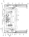
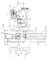
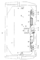
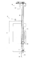
- FIG. 7 It is the schematic of the battery exchange system concerning embodiment of this invention. It is a perspective view of the battery exchange system shown in FIG. It is a perspective view which shows the E section of FIG. 2 from another angle. It is an enlarged view of the F section of FIG. It is a front view which shows the state in which the battery was accommodated in the battery accommodating part shown in FIG. It is an enlarged view of the G section of FIG. It is a figure which shows the battery insertion / extraction mechanism and lifting mechanism shown in FIG. 2 from the front. It is a figure which shows a battery insertion / extraction mechanism and a raising / lowering mechanism from the HH direction of FIG. It is a figure for demonstrating the battery mounting mechanism shown in FIG. 7 from the front.
- FIG. 7 It is a figure for demonstrating the battery mounting mechanism shown in FIG. 7 from a side surface. It is a figure for demonstrating the battery mounting mechanism shown in FIG. 7 from the upper surface. It is an expanded sectional view of the roller shown in FIG. It is a figure for demonstrating the battery moving mechanism shown in FIG. 7 from the front. It is a figure for demonstrating the battery moving mechanism shown in FIG. 7 from a side surface. It is a figure for demonstrating a state when the battery engaging part shown in FIG. 14 moves to the direction away from a bus
- (A) is an enlarged view of a portion M in FIG. 18, and (B) is an enlarged view of a portion N in FIG.
- FIG. 3 It is a figure for demonstrating the locus
- storage part of the control part of the battery exchange robot shown in FIG. 3 is a flowchart for explaining an example of a control method for the battery exchange robot shown in FIG. 2.
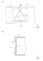
- (A) is a figure for demonstrating from the front the detection mark concerning other embodiment of this invention
- (B) is sectional drawing of the WW cross section of (A).
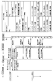
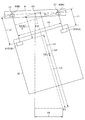
- It is a block diagram for demonstrating the structure of the control part of the battery exchange system shown in FIG. It is a sequence diagram for demonstrating an example of the control method of the battery exchange system shown in FIG. It is a figure for demonstrating the various values calculated at the time of the calibration of the battery detection position in the battery exchange robot shown in FIG. It is a figure for demonstrating the various values calculated at the time of the calibration of the battery detection position in the battery exchange robot shown in FIG. It is a figure for demonstrating the various values calculated at the time of the calibration of the battery detection position in the battery exchange robot shown in FIG. It is a figure for demonstrating the various values calculated at the time of the calibration of the battery detection position in the battery exchange robot shown in FIG.
- FIG. 3 It is a figure for demonstrating the various values calculated at the time of the calibration of the battery detection position in the battery exchange robot shown in FIG. 3 is a flowchart for explaining an example of a control method for the battery exchange robot shown in FIG. 2. It is a figure for demonstrating the various values calculated at the time of battery replacement with the battery replacement robot shown in FIG. It is a figure for demonstrating the various values calculated at the time of battery replacement with the battery replacement robot shown in FIG. It is a figure for demonstrating the various values calculated at the time of battery replacement with the battery replacement robot shown in FIG. It is a figure for demonstrating the various values calculated at the time of battery replacement with the battery replacement robot shown in FIG. It is a figure for demonstrating the various values calculated at the time of battery replacement with the battery replacement robot shown in FIG.
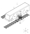
- FIG. 1 is a schematic diagram of a battery exchange system 1 according to an embodiment of the present invention.
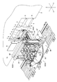
- FIG. 2 is a perspective view of the battery exchange system 1 shown in FIG.
- FIG. 3 is a perspective view showing the portion E of FIG. 2 from another angle.
- each of the three directions orthogonal to each other is defined as an X direction, a Y direction, and a Z direction.
- the Z direction coincides with the vertical direction (vertical direction).
- the X direction is the front-rear direction
- the Y direction is the left-right direction.
- the battery exchange system 1 of this embodiment is a system for exchanging the battery 3 mounted on the vehicle 2.
- the vehicle 2 of this embodiment is an electric bus. Therefore, hereinafter, the vehicle 2 is referred to as “bus 2”.
- a battery housing portion 4 in which a plurality of batteries 3 are housed is attached to the bus 2.
- the battery accommodating portions 4 are attached to the both side surfaces 2 a of the bus 2.
- the battery accommodating portion 4 is disposed so as to be exposed to the side surface 2a when a cover member (not shown) attached to the side surface 2a is removed. Further, the battery accommodating portion 4 is disposed below the seat of the bus 2.
- the bus 2 is stopped so that the traveling direction thereof substantially coincides with the left-right direction.
- the battery accommodating portion 4 attached to the side surface 2a of the stopped bus 2 is referred to as the first battery accommodating portion 4A, and the other of the bus 2 is The battery housing part 4 attached to the side surface 2a of the battery is referred to as a second battery housing part 4B.
- the battery exchange system 1 includes two battery exchange robots 5 (hereinafter referred to as “robots 5”) for exchanging the batteries 3 housed in the battery housing portions 4 attached to both side surfaces 2a of the bus 2. And). That is, the battery exchange system 1 includes a robot 5 as a first battery exchange robot for exchanging the battery 3 housed in the first battery housing portion 4A, and the battery 3 housed in the second battery housing portion 4B. And a robot 5 as a second battery exchange robot for exchanging the battery. The robot 5 faces the side surface 2a of the bus 2 in the front-rear direction so that the battery 3 housed in the battery housing portion 4 can be replaced.
- the robot 5 pulls out the battery 3 housed in the battery housing portion 4 and carries it into a buffer station (not shown), and unloads the charged battery 3 housed in the buffer station from the buffer station. Insert into the housing 4.
- the robot 5 for replacing the battery 3 accommodated in the first battery accommodating portion 4A is referred to as the first robot 5A
- the second battery accommodating portion 4B is referred to as the second battery accommodating portion 4B
- the robot 5 for exchanging the accommodated battery 3 is referred to as a second robot 5B.
- a detection plate 9 for detecting the position of the bus 2 is formed or fixed on the side surface 2 a of the bus 2.
- the detection plate 9 is formed in a flat plate shape, and is formed in a substantially rectangular shape having a substantially constant width in the vertical direction.
- This detection plate 9 is disposed, for example, on the front side of the battery housing portion 4 in the traveling direction of the bus 2. Further, the detection plate 9 is disposed so as to be exposed to the side surface 2a when a cover member (not shown) attached to the side surface 2a is removed.
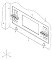
- FIG. 4 is an enlarged view of a portion F in FIG.
- FIG. 5 is a front view showing a state in which the battery 3 is accommodated in the battery accommodating portion 4 shown in FIG.
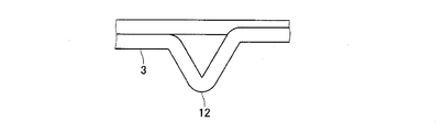
- FIG. 6 is an enlarged view of a portion G in FIG.
- the battery housing part 4 includes a battery cradle 6 on which the battery 3 is mounted and left and right side walls 7, and the battery cradle 6 and the side walls 7 form a housing space for the battery 3.
- the battery accommodating portion 4 is formed with accommodating spaces for a plurality of batteries 3 so that a plurality of batteries 3 can be accommodated. That is, a plurality of batteries 3 can be mounted on the bus 2.
- Four batteries 3 can be mounted on the bus 2 of this embodiment, and the battery housing portion 4 includes four battery mounts 6 on which each of the four batteries 3 is mounted.
- the two battery mounts 6 are disposed so as to be adjacent in the left-right direction via the side wall 7 and are adjacent to the two battery mounts 6 adjacent in the left-right direction in the left-right direction.
- the other two battery mounts 6 are arranged so as to overlap in the vertical direction.
- a detection mark 8 for indirectly detecting the position of the battery 3 is formed on the front surface of the battery stand 6.
- the detection mark 8 is formed on each of both ends in the left-right direction of the battery mount 6. That is, a pair of (two) detection marks 8 are formed on the front surface of the battery stand 6 with a predetermined interval in the left-right direction.
- the battery housing portion 4 of this embodiment includes the four battery mounts 6, and the battery housing portion 4 is formed with four pairs of detection marks 8.
- the detection mark 8 is formed in a flat plate shape that protrudes from the front surface of the battery mount 6, and is formed in a substantially triangular shape whose width changes in the vertical direction. Specifically, the detection mark 8 is formed in a substantially equilateral triangle shape whose width becomes narrower toward the upper side.
- a handle portion 11 for pulling out the battery 3 from the battery housing portion 4 is formed on the front surface of the battery 3.
- the handle portion 11 is formed on each of the left and right ends of the front surface of the battery 3.
- a protrusion 12 for positioning the battery 3 pulled out by the robot 5 in a direction perpendicular to the pulling direction is formed so as to protrude downward (see FIG. 6).
- the battery 3 includes a fixing member 13 (see FIG. 5) for fixing the battery 3 to the battery housing portion 4 and a release member 14 (see FIG. 4) for releasing the fixed state of the battery 3 with respect to the battery housing portion 4. ).
- the fixing member 13 is attached to the battery 3 so as to protrude from the left and right side surfaces of the battery 3.
- the fixing member 13 is attached to the front side of the battery 3.
- the fixing member 13 is held by the battery 3 so as to be movable in the left-right direction.
- the fixing member 13 is urged outward in the left-right direction by an urging member (not shown).
- the urging force of the urging member causes the right and left outer end portions of the fixing member 13 to engage with the engagement holes formed in the side wall 7 of the battery housing portion 4, so that the battery housing portion 4 is brought into contact with the battery housing portion 4. 3 is fixed.
- the fixing member 13 functions to position the battery 3 in the front-rear direction and the up-down direction in the battery housing portion 4.
- the release member 14 is disposed on the back side of the handle portion 11.
- the release member 14 is held by the battery 3 so as to be movable in the front-rear direction.
- the release member 14 is urged toward the front side of the battery 3 by an urging member (not shown).
- an urging member not shown.
- the fixing member 13 moves inward in the left-right direction, and the engagement hole formed in the side wall 7 of the battery housing portion 4 engages with the fixing member 13. The state is released, and the battery 3 can be pulled out from the battery housing 4.
- a connector connected to a connector disposed at the back of the battery housing 4 is attached to the back surface of the battery 3.
- a positioning pin for positioning the battery 3 in the up / down / left / right directions in the battery housing 4 is attached to the back surface of the battery 3.
- the robot 5 includes a battery insertion / removal mechanism 17 that pulls out the four batteries 3 from the bus 2 and inserts the four batteries 3 into the bus 2, and a battery insertion / removal mechanism.
- a horizontal movement mechanism 20 for moving in the left-right direction.
- the robot 5 also includes a detection mechanism 21 for detecting the detection mark 8 and the detection plate 9.
- the battery insertion / removal mechanism 17 includes a battery mounting mechanism 23 having a battery mounting portion 22 on which the battery 3 is mounted when the battery 3 is pulled out and inserted, and a battery mounting mechanism that is engaged with the battery 3 when the battery 3 is pulled out and inserted. And a battery moving mechanism 25 having a battery engaging portion 24 (see FIG. 7) for moving the battery 3 on the portion 22.
- the battery mounting portion 22 and the battery engaging portion 24 are movable in a direction approaching the bus 2 and a direction away from the bus 2.
- the battery insertion / removal mechanism 17 is held by a holding member 26 formed in a substantially rectangular tube shape.
- the holding member 26 includes a first holding member 27 constituting the lower end side thereof and a second holding member 28 constituting the upper end side thereof.
- the first holding member 27 is formed in a rectangular groove shape that opens on the upper side
- the second holding member 28 is formed in a rectangular groove shape that opens on the lower side.
- the holding member 26 is a substantially square in which both ends of the battery mounting portion 22 and the battery engaging portion 24 in the moving direction are opened by the first holding member 27 and the second holding member 28 being combined and fixed in the vertical direction. It is formed in a cylindrical shape.
- FIG. 7 is a diagram showing the battery insertion / removal mechanism 17 and the lifting mechanism 18 shown in FIG. 2 from the front.
- FIG. 8 is a view showing the battery insertion / removal mechanism 17 and the elevating mechanism 18 from the HH direction of FIG.
- FIG. 9 is a view for explaining the battery mounting mechanism 23 shown in FIG. 7 from the front.
- FIG. 10 is a view for explaining the battery mounting mechanism 23 shown in FIG. 7 from the side.
- FIG. 11 is a view for explaining the battery mounting mechanism 23 shown in FIG. 7 from above.
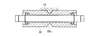
- 12 is an enlarged cross-sectional view of the roller 32 shown in FIG.
- the battery mounting mechanism 23 includes a mounting unit moving mechanism 30 that moves the battery mounting unit 22 in a direction approaching the bus 2 and a direction away from the bus 2 in addition to the battery mounting unit 22 described above.
- the battery mounting portion 22 is formed in a flat block shape that is flat in the vertical direction.
- a plurality of rollers 31 and 32 that are in contact with the lower surface of the battery 3 are rotatably attached to the upper surface of the battery mounting portion 22.
- the plurality of rollers 31 are arranged at predetermined intervals in the moving direction of the battery mounting portion 22, and the plurality of rollers 32 are also set in the moving direction of the battery mounting portion 22 in the same manner as the rollers 31. Arranged at intervals.
- the roller 31 and the roller 32 are arranged with a predetermined interval in a direction orthogonal to the moving direction of the battery mounting portion 22.
- the roller 31 is a flat roller.
- the roller 32 is a grooved roller in which a groove 32a that is recessed toward the inner peripheral side is formed on the outer peripheral surface.
- the groove 32a is formed so that the protrusion 12 formed on the lower surface of the battery 3 can be engaged, and when the battery 3 is mounted at a predetermined position of the battery mounting portion 22, the protrusion is formed on the groove 32a. 12 is engaged.
- the protrusion 3 is engaged with the groove 32 a, whereby the battery 3 is positioned with respect to the battery mounting portion 22 in a direction orthogonal to the moving direction of the battery mounting portion 22.
- the mounting unit moving mechanism 30 includes a motor 33, a screw member 34 such as a ball screw, and a nut member 35 that is screwed into the screw member 34 as a configuration for moving the battery mounting unit 22. Further, the mounting unit moving mechanism 30 is configured to guide the battery mounting unit 22, and is linearly formed, and engages with the guide rail 36 and is relatively movable along the guide rail 36. A guide block 37 is provided.
- the motor 33 is fixed to the upper surface side of the rear end portion of the battery mounting portion 22.
- the screw member 34 is rotatably held on the lower surface side of the battery mounting portion 22.
- the motor 33 and the screw member 34 are connected via a pulley, a belt, or the like.
- the nut member 35 is fixed to the first holding member 27.
- the guide rail 36 is fixed to the lower surface side of the battery mounting portion 22, and the guide block 37 is fixed to the first holding member 27. Therefore, in this embodiment, when the motor 33 rotates, the battery mounting portion 22 is guided by the guide rail 36 and the guide block 37 and moves linearly with respect to the first holding member 27.
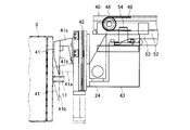
- FIG. 13 is a view for explaining the battery moving mechanism 25 shown in FIG. 7 from the front.
- FIG. 14 is a view for explaining the battery moving mechanism 25 shown in FIG. 7 from the side.
- FIG. 15 is a view for explaining the state when the battery engaging portion 24 shown in FIG. 14 moves away from the bus 2 from the side.
- FIG. 16 is an enlarged view of a portion J in FIG.
- FIG. 17 is an enlarged view of a portion K in FIG.
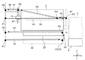
- FIG. 18 is a view for explaining the battery moving mechanism 25 shown in FIG. 7 from above.
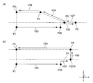
- FIG. 19A is an enlarged view of a portion M in FIG. 18, and
- FIG. 19B is an enlarged view of a portion N in FIG.
- the battery moving mechanism 25 includes an engaging portion moving mechanism 39 that moves the battery engaging portion 24 in a direction approaching the bus 2 and a direction away from the bus 2, and a battery engaging portion 24. And a movable holding member 40 that is held movably and held by the second holding member 28.
- the battery engaging portion 24 includes an engaging claw portion 41 that engages with the handle portion 11 of the battery 3, an air cylinder 42 that moves the engaging claw portion 41 up and down, and a base portion 43 to which the air cylinder 42 is attached. Yes.
- the engaging claw portion 41 is fixed to the movable side of the air cylinder 42, and the fixed side of the air cylinder 42 is fixed to the distal end surface of the base portion 43.
- the two engaging claws 41 and the two air cylinders 42 of the base 43 are arranged so that the engaging claws 41 are engaged with the two handles 11 formed on the battery 3. It arrange
- the engaging claw portion 41 includes a fixing portion 41 a that is fixed to the air cylinder 42 and a claw portion 41 b that engages with the handle portion 11.
- the claw portion 41 b enters from the upper side between the front end portion of the handle portion 11 and the front surface of the battery 3 and engages with the handle portion 11.
- the claw portion 41 b pushes the release member 14 to release the engagement state between the engagement hole formed in the side wall 7 of the battery housing portion 4 and the fixing member 13. To do. Therefore, when the claw portion 41 b is engaged with the handle portion 11, the battery 3 can be pulled out and inserted by the battery pulling mechanism 17.
- the moving holding member 40 is formed in a long and narrow shape in the moving direction of the battery engaging portion 24. Further, the movement holding member 40 is formed so that the shape when viewed from the moving direction of the battery engaging portion 24 is substantially H-shaped.
- the engaging portion moving mechanism 39 includes a motor 44, a screw member 45 such as a ball screw, a nut member 46 that is screwed to the screw member 45, and a structure for moving the battery engaging portion 24 and the movement holding member 40. Pulleys 47 and 48 and a belt 49 spanning the pulleys 47 and 48 are provided. Further, the engaging portion moving mechanism 39 is configured to guide the battery engaging portion 24 and the movement holding member 40, and engages with the guide rail 50 formed in a straight line, the guide rail 50, and the guide rail 50. And a guide block 51 that is relatively movable along the guide rail 52. As a configuration for guiding the battery engaging portion 24, the guide rail 52 that is linearly formed, and the guide rail 52 that engages with the guide rail 52 and And a guide block 53 that is relatively movable along.
- the motor 44 is fixed to the upper surface of the rear end portion of the second holding member 28.
- the screw member 45 is rotatably held on the upper surface portion of the second holding member 28.
- the motor 44 and the screw member 45 are connected via a pulley, a belt, or the like.
- the nut member 46 is fixed to the rear end portion of the movement holding member 40.
- the pulley 47 is rotatably held at the rear end portion of the movement holding member 40, and the pulley 48 is rotatably held at the front end portion of the movement holding member 40.
- the belt 49 is fixed to the base portion 43 of the battery engaging portion 24 via the belt fixing member 54 and is fixed to the upper surface portion of the second holding member 28 via the belt fixing member 55.
- the movable holding member 40 protrudes from the second holding member 28 and the belt fixing member 55 is disposed in the vicinity of the pulley 47 as shown in FIG. 17, the pulley as shown in FIG.
- the belt fixing member 54 is disposed in the vicinity of 48, and the movable holding member 40 is accommodated in the second holding member 28, and the belt fixing member 55 is disposed in the vicinity of the pulley 48 as shown in FIG.
- the belt 49 is fixed to the base 43 and the second holding member 28 via the belt fixing members 54 and 55 so that the belt fixing member 54 is disposed in the vicinity of the pulley 47.
- the guide rail 50 is fixed to the upper surface portion of the second holding member 28, and the guide block 51 is fixed to the upper surface of the movable holding member 40.
- the guide rail 52 is fixed to the lower surface of the movement holding member 40, and the guide block 53 is fixed to the upper end side of the base portion 43 of the battery engaging portion 24.
- the moving holding member 40 when the motor 44 is rotated, the moving holding member 40 is guided to the guide rail 50 and the guide block 51 together with the battery engaging portion 24 by the screw member 45 and the nut member 46, so that the second holding member 28 is moved. Move in a straight line.
- the motor 44 rotates, the battery engaging portion 24 is guided by the guide rail 52 and the guide block 53 by the pulleys 47 and 48 and the belt 49, and relatively moves linearly with respect to the movement holding member 40.
- the elevating mechanism 18 includes a moving direction of the battery mounting portion 22 and the battery engaging portion 24 (hereinafter, this direction is referred to as a “first direction”) and a vertical direction.
- the first elevating mechanism 59 and the second elevating mechanism 60 are provided on both ends of a direction orthogonal to the direction (hereinafter, this direction is referred to as “second direction”).
- the first elevating mechanism 59 is connected to one end side of the first holding member 27 in the second direction by the first connecting mechanism 61.
- the second elevating mechanism 60 is connected to the other end side of the first holding member 27 in the first direction by the second connecting mechanism 62.
- the first elevating mechanism 59 and the second elevating mechanism 60 are provided to incline the holding member 26 with respect to the horizontal direction (that is, the second direction when viewed from the first direction, that is, the battery mounting portion 22 and the battery engaging portion). In order to incline the holding member 26 with respect to the second direction when viewed from the direction of movement 24), it can be driven individually.
- the holding member 26 is connected to the first elevating mechanism 59 and the second elevating mechanism 60 so as to be inclined with respect to the horizontal direction.
- the first elevating mechanism 59 and the second elevating mechanism 60 include an elevating member 63 that is movable in the vertical direction, a columnar member 64 that holds the elevating member 63 so as to be able to elevate, and an elevating drive mechanism 65 that elevates the elevating member 63.
- the columnar member 64 is formed in a column shape elongated in the vertical direction. As shown in FIG. 7, the upper end of the columnar member 64 constituting the first elevating mechanism 59 and the upper end of the columnar member 64 constituting the second elevating mechanism 60 are connected by a connecting member 66, and two pieces The columnar member 64 and the connecting member 66 constitute a portal frame.
- the elevating drive mechanism 65 includes a motor 67, a screw member 68 such as a ball screw, and a nut member 69 screwed to the screw member 68 as a configuration for elevating the elevating member 63. Yes.
- the elevating drive mechanism 65 is configured to guide the elevating member 63, and engages with the guide rail 70 formed in a straight line, along the guide rail 70 and along the guide rail 70.
- the guide block 71 is relatively movable.
- the motor 67 is fixed to the upper end side of the columnar member 64.
- the screw member 68 is rotatably held by the columnar member 64.
- the motor 67 and the screw member 68 are connected via a coupling 72.
- the nut member 69 is fixed to the elevating member 63.
- the guide rail 70 is fixed to the side surface of the columnar member 64.
- the guide block 71 is fixed to the elevating member 63. Therefore, in this embodiment, when the motor 67 rotates, the elevating member 63 is guided by the guide rail 70 and the guide block 71 and moves up and down with respect to the columnar member 64.
- the first connecting mechanism 61 connects the holding member 26 and the lifting member 63 so that the holding member 26 can be rotated relative to the lifting member 63 of the first lifting mechanism 59.
- the second connecting mechanism 62 is configured so that the holding member 26 and the elevating member 63 are capable of relative rotation of the holding member 26 with respect to the elevating member 63 of the second elevating mechanism 60 and relative movement in the second direction.
- the motor 67 rotates so that the moving amount of the lifting member 63 of the first lifting mechanism 59 is equal to the moving amount of the lifting member 63 of the second lifting mechanism 60, the holding member 26 is parallel to the horizontal direction. Go up and down while maintaining the state.
- the holding member 26 tilts with respect to the horizontal direction. Further, when the motor 67 rotates so that the moving amount of the lifting member 63 of the first lifting mechanism 59 and the moving amount of the lifting member 63 of the second lifting mechanism 60 are different, the holding member 26 is lifted while being inclined with respect to the horizontal direction. To do.
- the rotation mechanism 19 includes a battery insertion / removal mechanism 17 and an elevating mechanism 18, and a rotation member 85 that can rotate, and a rotation that rotates the rotation member 85.
- a drive mechanism 86 As shown in FIGS. 2 and 3, the horizontal movement mechanism 20 includes a slide member 87, which is mounted with a battery insertion / removal mechanism 17, an elevating mechanism 18, and a rotation mechanism 19, and is movable in the left-right direction. And a horizontal drive mechanism 88 for movement.
- Rotating member 85 is formed in a substantially disc shape.
- the slide member 87 is formed in a substantially rectangular plate shape whose longitudinal direction is the left-right direction.
- the width of the slide member 87 in the left-right direction is larger than the diameter of the rotating member 85, and the width of the slide member 87 in the front-rear direction is smaller than the diameter of the rotating member 85.
- Rotating member 85 is disposed on the upper side of slide member 87.
- the turning member 85 can turn around the center of curvature.
- the lower ends of the two columnar members 64 are fixed to the upper surface of the rotating member 85.
- the lower ends of the columnar members 64 are fixed to both end sides of the upper surface of the rotating member 85 in the first direction orthogonal to the moving direction of the battery mounting portion 22 and the battery engaging portion 24.
- the rotation drive mechanism 86 includes a motor, a pulley, a belt, and the like as a configuration for rotating the rotation member 85. Further, the rotation drive mechanism 86 is configured to guide the rotation member 85 in the rotation direction, and a guide rail and a plurality of guide blocks that engage with the guide rail and are relatively movable along the guide rail. It has.
- the guide rail is formed in an annular shape and is fixed to the upper surface of the slide member 87.
- the plurality of guide blocks are fixed to the lower surface side of the rotating member 85 and are arranged in an annular shape centering on the center of curvature of the rotating member 85.
- a belt is stretched over the pulley fixed to the output shaft of the motor and the outer peripheral surface of the rotating member 85, and when the motor rotates, the rotating member 85 is guided by the guide rail and the guide block to slide. It rotates with respect to 87.
- the horizontal drive mechanism 88 includes a motor, a pulley, a belt, and the like as a configuration for moving the slide member 87. Further, the horizontal drive mechanism 88 is configured to guide the slide member 87 in the left-right direction, and a plurality of guide rails that are linearly formed and a plurality of guide rails that are engaged with the guide rails and are relatively movable along the guide rails. And a guide block.
- the guide rail is disposed below the slide member 87.
- the guide block is fixed to the lower surface of the slide member 87.
- One end of the belt is fixed to the left end side of the guide rail, and the other end of the belt is fixed to the right end side of the guide rail.
- the belt is stretched around a pulley or the like fixed to the output shaft of the motor. When the motor rotates, the slide member 87 is linearly moved in the left-right direction by being guided by the guide rail and the guide block.
- FIG. 20 is a diagram showing the state when the position of the bus 2 is detected by the detection mechanism 21 shown in FIG. 11 from the top.
- FIG. 21 is a schematic diagram for explaining a method of detecting the position of the bus 2 by the detection mechanism 21 shown in FIG.
- FIG. 22 is a diagram showing a state when the position of the battery 3 is detected by the detection mechanism 21 shown in FIG.
- FIG. 23 is a diagram for explaining a method of detecting the position of the battery 3 by the detection mechanism 21 shown in FIG.
- the detection mechanism 21 is a laser sensor that includes a light emitting unit that emits laser light, and a light receiving unit that receives the laser light emitted from the light emitting unit and reflected by the side surface 2a of the bus 2, the front surface of the battery mount 6, and the like. is there. As shown in FIG. 11, the detection mechanism 21 is attached to the upper surface on the front end side of the battery mounting portion 22. The detection mechanism 21 is attached to the battery mounting portion 22 such that the light emitting portion and the light receiving portion are adjacent in the horizontal direction, or the light emitting portion and the light receiving portion are adjacent in the vertical direction. In this embodiment, two detection mechanisms 21 are attached to the battery mounting portion 22 so as to correspond to a pair of (two) detection marks 8 formed on each of the four battery mounts 6. .
- the detection mechanism 21 is fixed to the upper surfaces of both ends of the battery mounting portion 22 in the first direction orthogonal to the moving direction of the battery mounting portion 22 and the battery engaging portion 24. Two detection mechanisms 21 are fixed to the battery mounting portion 22 at the same interval as the interval between the pair of detection marks 8.
- the detection mechanism 21 is turned on when a reflector that reflects the laser light emitted from the light emitting unit is within a predetermined measurement range, and is turned off when the reflector that reflects the laser light is not within the measurement range. become.
- the detection mechanism 21 can detect the distance between the detection mechanism 21 and the reflecting object when the detection mechanism 21 is on.
- the detection of the position of the bus 2 by the detection mechanism 21 is performed as follows, for example. That is, when the bus 2 in which the battery 3 is replaced stops at a predetermined stop position, for example, the battery insertion / removal mechanism 17 stands by at a position where the detection plate 9 is disposed in the left-right direction. At this time, as indicated by a solid line in FIG. 20, the front surface of the battery mounting portion 22 faces the side surface 2 a of the bus 2, and the battery mounting portion 22 is retracted in a direction away from the bus 2.
- the battery is mounted until the detection mechanism 21 that receives the laser light emitted from the light emitting portion of the detection mechanism 21 and reflected by the detection plate 9 is turned on.
- Part 22 advances toward bus 2.
- the battery mounting portion 22 at a predetermined position in the vertical direction is moved upward as shown by a broken line in FIG.
- the approximate position of the upper end of the detection plate 9 is detected by 21.
- the battery mounting portion 22 is moved downward to a height for detecting the positions of both ends of the detection plate 9 in the left-right direction.
- the battery mounting portion 22 is moved to one side in the left-right direction, and the detection mechanism 21 detects one end of the detection plate 9 in the left-right direction. The approximate position is detected. Thereafter, the battery mounting portion 22 is moved to the other in the left-right direction as shown by the solid line in FIG. 21C and the two-dot chain line in FIG. 21D, and the detection mechanism 21 moves the detection plate 9 in the left-right direction. Detect the position of both ends.
- the battery mounting portion 22 is located at a predetermined distance from the position where one end of the detection plate 9 in the left-right direction is detected by the detection mechanism 21 to the other in the left-right direction. Then, the upper end of the detection plate 9 is detected by the detection mechanism 21 as shown by the solid line in FIG. 21D and the two-dot chain line in FIG. Thereafter, as shown by a broken line in FIG. 21E, the battery mounting portion 22 is moved a predetermined distance from the position where the detection mechanism 21 detects the other end of the detection plate 9 in the left-right direction to the other in the left-right direction. After moving to a distant position and downward, it is moved upward as indicated by the solid line in FIG. 21E, and the upper end of the detection plate 9 is detected by the detection mechanism 21.
- the detection mechanism 21 detects the position of the detection plate 9 in the front-rear direction, the left-right direction, and the up-down direction. Further, the position of the bus 2 is detected by detecting the position of the detection plate 9 in the front-rear direction, the left-right direction, and the vertical direction by the detection mechanism 21. Further, by moving the battery mounting portion 22 as described above, the detection mechanism 21 can detect the inclination of the detection plate 9 with respect to the left-right direction when viewed from the front-rear direction. That is, by moving the battery mounting portion 22 as described above, the detection mechanism 21 can detect the inclination of the bus 2 with respect to the left-right direction when viewed from the front-rear direction.
- the position of the upper end plate 9 of the detection plate 9 is detected by the detection mechanism 21 by moving the battery mounting portion 22 in the vertical direction and the horizontal direction. Further, the detection mechanism 21 detects the positions of the detection plate 9 in the front-rear direction, the left-right direction and the up-down direction and the position of the detection plate 9 in the up-down direction by detecting the positions of the front-rear direction, left-right direction, and left and right ends. The position of the bus 2 is detected. In addition, by moving the battery mounting portion 22 in the vertical direction and the horizontal direction, the detection mechanism 21 can detect the inclination of the detection plate 9 with respect to the horizontal direction when viewed from the front-rear direction. That is, by moving the battery mounting portion 22 in the vertical direction and the horizontal direction, the detection mechanism 21 can detect the inclination of the bus 2 with respect to the horizontal direction when viewed from the front-rear direction.
- the position of the battery 3 is detected by the detection mechanism 21 as follows. That is, first, as shown in FIG. 22A, each of the pair of detection marks 8 of the battery mount 6 on which the battery 3 to be replaced is mounted and each of the two detection mechanisms 21 face each other. Next, the battery mounting portion 22 is moved in the left-right direction.
- the battery mounting portion 22 is advanced toward the battery mount 6 until the detection mechanism 21 receiving the laser light emitted from the light emitting portion of the detection mechanism 21 and reflected by the detection mark 8 is turned on. Thereafter, as shown in FIGS. 22B and 22C and FIGS. 23A and 23B, the battery so that the laser light from the light emitting portion of the detection mechanism 21 crosses the detection mark 8 in the left-right direction.
- the mounting portion 22 is moved in the left-right direction. More specifically, the battery mounting portion 22 is moved in the left-right direction so that the laser beams from the respective light-emitting portions of the two detection mechanisms 21 traverse each of the two detection marks 8 in the left-right direction.
- a portion that is, it is possible to detect the width of the portion that reflects the laser light (the broken line portion in FIG. 23C), hereinafter referred to as “detected portion 8a”. Since the detection mark 8 of this embodiment is formed in a substantially triangular shape whose width changes in the vertical direction, detecting the width of the detected portion 8a of the detection mark 8 increases the height of the detection mark 8. It is possible to detect the height of the battery holder 6 on which the detection mark 8 is formed by detecting the height of the detection mark 8.
- the detection mechanism 21 detects the width of the detected portion 8a of the detection mark 8 to detect the height of the battery cradle 6 and the height of the battery cradle 6 is detected. The height of the battery 3 mounted on the battery stand 6 is detected.
- the detection mark 8 is detected by moving the battery mounting portion 22 so that the laser light from the light emitting portion of the detection mechanism 21 traverses the detection mark 8 in the left-right direction, and detecting the detection mark 8 by the detection mechanism 21. It is possible to detect the center position in the left-right direction of the eight detected portions 8a. In this embodiment, for example, the position of the battery cradle 6 in the left-right direction is detected based on this center position, and the position of the battery cradle 6 in the left-right direction is detected, so that the battery cradle 6 is positioned. The position of the mounted battery 3 in the left-right direction is detected.
- the distance between the center position in the left-right direction of the detected portion 8a of the detection mark 8 and the detection mechanism 21 can be detected by the detection mechanism 21.
- the center position and the detection mechanism 21 are detected.
- the position of the battery cradle 6 in the front-rear direction is detected based on the distance between and the position of the battery cradle 6 in the front-rear direction, thereby detecting the position of the battery 3 that is positioned and mounted on the battery cradle 6. A position in the front-rear direction is detected.
- the height of the battery cradle 6 detected by one of the two detection mechanisms 21 and the height of the battery cradle 6 detected by the other detection mechanism 21 are viewed in the front-rear direction.
- the inclination of the battery mount 6 with respect to the left-right direction is detected.
- the inclination of the battery stand 6 with respect to the left-right direction when viewed from the front-rear direction is detected.
- the inclination of the battery mount 6 with respect to the left-right direction when viewed from the up-down direction is detected. Further, by detecting the inclination of the battery pedestal 6 with respect to the left-right direction when viewed from the vertical direction, the inclination of the battery 3 with respect to the left-right direction when viewed from the vertical direction is detected.
- the position of the battery 3 in the front-rear and left-right directions, the height of the battery 3, the inclination of the battery 3 with respect to the left-right direction when viewed from the front-rear direction, and the inclination of the battery 3 with respect to the left-right direction when viewed from the up-down direction are detected.
- the protrusion 12 on the lower surface of the battery 3 and the groove 32a of the roller 32 of the battery mounting portion 22 substantially coincide with each other in the left-right direction, and the lower surface of the battery 3 and the upper surfaces of the rollers 31 and 32 substantially coincide with each other.
- the inclination of the battery 3 with respect to the left and right direction when viewed from the direction and the inclination of the battery insertion and removal mechanism 17 substantially coincide with each other, and the inclination of the battery 3 with respect to the left and right direction when viewed from the upper and lower direction
- the position of the battery insertion / removal mechanism 17 in the left-right direction during the replacement operation of the battery 3 by the robot 5 so that the inclination substantially coincides, And inclination are adjusted.
- the horizontal position of the battery insertion / removal mechanism 17 is adjusted by the horizontal movement mechanism 20, the height of the battery insertion / removal mechanism 17 is adjusted by the elevating mechanism 18, and the vertical direction is adjusted by the rotation mechanism 19.
- the inclination of the battery insertion / removal mechanism 17 with respect to the left / right direction when viewed is adjusted. Further, by driving one of the first elevating mechanism 59 and the second elevating mechanism 60, or by changing the drive amount of the first elevating mechanism 59 and the drive amount of the second elevating mechanism 60, the front and rear directions can be seen. The inclination of the battery insertion / removal mechanism 17 with respect to the left / right direction is adjusted.
- FIG. 20 is a diagram showing the state when the position of the bus 2 is detected by the detection mechanism 21 shown in FIG. 11 from the top.
- FIG. 22 is a diagram showing a state when the position of the battery 3 is detected by the detection mechanism 21 shown in FIG.
- FIG. 23 is a diagram for explaining a method of detecting the position of the battery 3 by the detection mechanism 21 shown in FIG.
- the detection mechanism 21 includes a light emitting unit that emits laser light, and a light receiving unit that receives the laser light emitted from the light emitting unit and reflected by a reflector such as the side surface 2a of the bus 2 or the front surface of the battery mount 6. It is a laser sensor. As shown in FIG. 11, the detection mechanism 21 is attached to the upper surface on the front end side of the battery mounting portion 22. The detection mechanism 21 is attached to the battery mounting portion 22 such that the light emitting portion and the light receiving portion are adjacent in the horizontal direction, or the light emitting portion and the light receiving portion are adjacent in the vertical direction. In this embodiment, two detection mechanisms 21 are attached to the battery mounting portion 22 so as to correspond to a pair of (two) detection marks 8 formed on each of the four battery mounts 6.
- the detection mechanism 21 is fixed to the upper surfaces of both ends of the battery mounting portion 22 in the second direction orthogonal to the moving direction of the battery mounting portion 22 and the battery engaging portion 24. Two detection mechanisms 21 are fixed to the battery mounting portion 22 at the same interval as the interval between the pair of detection marks 8.
- the detection mechanism 21 is electrically connected to the control unit 91 of the robot 5 through a predetermined wiring.
- the detection mechanism 21 is turned on when a reflector that reflects the laser light emitted from the light emitting unit is within a predetermined measurement range, and is off when the reflector that reflects the laser light is not within the measurement range. It becomes a state.
- the distance between the detection mechanism 21 and the reflecting object can be detected using the detection mechanism 21 in the on state.
- one detection mark 8 is referred to as a detection mark 8A
- the other detection mark 8 is referred to as a detection mark 8B.
- one detection mechanism 21 for detecting the detection mark 8A is set as a detection mechanism 21A
- the other detection mechanism 21 for detecting the detection mark 8B is set as a detection mechanism 21B.
- the detection of the position of the bus 2 by the detection mechanism 21 is performed as follows, for example. That is, when the bus 2 in which the battery 3 is replaced stops at a predetermined stop position, for example, the battery insertion / removal mechanism 17 stands by at a position where the detection plate 9 is disposed in the left-right direction. At this time, as indicated by a solid line in FIG. 20, the front surface of the battery mounting portion 22 faces the side surface 2 a of the bus 2, and the battery mounting portion 22 is retracted in a direction away from the bus 2. From this state, as indicated by a two-dot chain line in FIG. The part 22 is advanced toward the bus 2.
- the control unit 91 performs the front-rear direction, the horizontal direction, and the vertical direction.
- the position of the bus 2 is detected by calculating the position of the detection plate 9 and calculating the position of the detection plate 9.
- the control unit 91 can calculate the inclination of the detection plate 9 with respect to the horizontal direction when viewed from the front-rear direction. That is, it is possible to detect the inclination of the bus 2 with respect to the left-right direction when viewed from the front-rear direction by moving the battery mounting portion 22 in the up-down direction and the left-right direction.
- the position of the battery 3 is detected by the detection mechanism 21 as follows. That is, first, as shown in FIG. 22A, each of the pair of detection marks 8 of the battery mount 6 on which the battery 3 to be replaced is mounted and each of the two detection mechanisms 21 face each other. Next, the battery mounting portion 22 is moved in the left-right direction.
- the battery mounting portion 22 is advanced toward the battery mount 6 until the detection mechanism 21 receiving the laser light emitted from the light emitting portion of the detection mechanism 21 and reflected by the detection mark 8 is turned on. Thereafter, as shown in FIGS. 22B and 22C and FIGS. 23A and 23B, the battery so that the laser light from the light emitting portion of the detection mechanism 21 crosses the detection mark 8 in the left-right direction.
- the mounting portion 22 is moved in the left-right direction. More specifically, the laser light from the light emitting part of the detection mechanism 21A crosses the detection mark 8A in the left-right direction, and the laser light from the light emission part of the detection mechanism 21B crosses the detection mark 8B in the left-right direction.
- the battery mounting portion 22 is moved in the left-right direction.
- a portion of the detection mark 8 that reflects the laser light from the detection mechanism 21 (a broken line portion in FIG. 23C).
- the detected portions 8a and 8b are used (more specifically, when the laser light emitted from the detection mechanism 21A crosses the detection mark 8A in the left-right direction, the laser light from the detection mechanism 21A of the detection mark 8A).
- the first reflected portion 8a is the portion to be reflected, and when the laser light emitted from the detection mechanism 21B crosses the detection mark 8B in the left-right direction, the laser light from the detection mechanism 21B of the detection mark 8B is reflected.
- the battery mounting portion 22 is moved in the left-right direction so that the laser light from the light-emitting portion of the detection mechanism 21 crosses the detection mark 8 in the left-right direction. If that, the detection mechanism 21, the detection portion 8a in the lateral direction, both end portions of 8b is detected.
- the control unit 91 can calculate the width of the detected portions 8a and 8b in the left and right direction. Further, since the detection mark 8 of this embodiment is formed in a substantially triangular shape in which the width in the left-right direction is gradually narrowed toward the upper side, the control unit 91 determines the width of the detected portions 8a, 8b in the left-right direction. The heights of the detected portions 8a and 8b can be calculated based on the above, and the height of the detection mark 8 can be calculated by calculating the heights of the detected portions 8a and 8b.
- the controller 91 can calculate the height of the battery cradle 6 on which the detection mark 8 is formed based on the widths of the detected portions 8a and 8b in the left-right direction. In this embodiment, by calculating the height of the battery cradle 6, the height of the battery 3 that is positioned and mounted on the battery cradle 6 is detected.
- the control unit 91 can calculate the center positions C1 and C2 of the detected parts 8a and 8b in the left and right direction. it can. Further, the control unit 91 can calculate the position in the left-right direction of the battery mount 6 where the detection mark 8 is formed based on the center positions C1 and C2. In this embodiment, by calculating the position of the battery cradle 6 in the left-right direction, the position of the battery 3 positioned and mounted on the battery cradle 6 is detected.
- control unit 91 can calculate the distance between the center positions C1 and C2 and the detection mechanism 21. Further, the control unit 91 can calculate the position in the front-rear direction of the battery cradle 6 on which the detection mark 8 is formed based on the distance between the center positions C1 and C2 and the detection mechanism 21. In this embodiment, by calculating the position of the battery cradle 6 in the front-rear direction, the position in the front-rear direction of the battery 3 that is positioned and mounted on the battery cradle 6 is detected.
- control is performed based on the height of the detection mark 8A calculated based on the width of the first detected portion 8a and the height of the detection mark 8B calculated based on the width of the second detected portion 8b.
- the unit 91 can calculate the inclination of the battery stand 6 with respect to the left-right direction when viewed from the front-rear direction. That is, based on the width of the first detected portion 8a and the width of the second detected portion 8b, the control unit 91 can calculate the inclination of the battery mount 6 with respect to the left-right direction when viewed from the front-rear direction. it can.
- the inclination of the battery cradle 6 with respect to the left-right direction when viewed from the front-rear direction is calculated, so that the inclination of the battery 3 with respect to the left-right direction when viewed from the front-rear direction is detected.
- control unit 91 determines from the distance between the center position C1 in the left-right direction of the first detected portion 8a and the detection mechanism 21A and the distance between the center position C2 in the left-right direction of the second detected portion 8b and the detection mechanism 21B. Can calculate the inclination of the battery mount 6 with respect to the left-right direction when viewed from the up-down direction. In this embodiment, the inclination of the battery cradle 6 with respect to the left-right direction when viewed from the vertical direction is detected, whereby the inclination of the battery 3 with respect to the left-right direction when viewed from the vertical direction is detected.
- the position of the battery 3 in the front-rear and left-right directions, the height of the battery 3, the inclination of the battery 3 with respect to the left-right direction when viewed from the front-rear direction, and the inclination of the battery 3 with respect to the left-right direction when viewed from the up-down direction are detected.
- the protrusion 12 on the lower surface of the battery 3 and the groove 32a of the roller 32 of the battery mounting portion 22 substantially coincide with each other in the left-right direction, and the lower surface of the battery 3 and the upper surfaces of the rollers 31 and 32 substantially coincide with each other.
- the inclination of the battery 3 with respect to the left and right direction when viewed from the direction and the inclination of the battery insertion and removal mechanism 17 substantially coincide with each other, and the inclination of the battery 3 with respect to the left and right direction when viewed from the upper and lower direction
- the position of the battery insertion / removal mechanism 17 in the left-right direction during the replacement operation of the battery 3 by the robot 5 so that the inclination substantially coincides, And inclination are adjusted.
- the horizontal position of the battery insertion / removal mechanism 17 is adjusted by the horizontal movement mechanism 20, the height of the battery insertion / removal mechanism 17 is adjusted by the elevating mechanism 18, and the vertical direction is adjusted by the rotation mechanism 19.
- the inclination of the battery insertion / removal mechanism 17 with respect to the left / right direction when viewed is adjusted. Further, by driving one of the first elevating mechanism 59 and the second elevating mechanism 60, or by changing the drive amount of the first elevating mechanism 59 and the drive amount of the second elevating mechanism 60, the front and rear directions can be seen. The inclination of the battery insertion / removal mechanism 17 with respect to the left / right direction is adjusted.
- FIG. 34 is a block diagram for explaining the configuration of the control unit 91 of the battery exchange system 1 shown in FIG.
- the control unit 91 of the battery exchange system 1 includes a first control unit 92 that controls the first robot 5A, a second control unit 93 that controls the second robot 5B, a first control unit 92, and a second control unit 93. And a common control unit 94 that is electrically connected.
- the first control unit 92 and the second control unit 93 are connected to the common control unit 94 in parallel.
- the common control unit 94 is electrically connected to a host control unit 95 that sends a control command to the control unit 91. That is, the first control unit 92 and the second control unit 93 are electrically connected to the host control unit 95 via the common control unit 94.
- FIG. 24 is a flowchart showing a schematic flow of the replacement operation of the battery 3 of the battery replacement robot 5 shown in FIG.
- FIG. 25 is a view for explaining the operation of extracting the battery 3 from the bus 2 by the battery exchange robot 5 shown in FIG.
- FIG. 26 is a diagram for explaining the operation of inserting the battery 3 into the bus 2 by the battery exchange robot 5 shown in FIG.
- step S1 when the bus 2 for replacing the battery 3 stops at a predetermined stop position, first, the position of the bus 2 is detected by the above-described procedure (step S1). Thereafter, the operation of pulling out the battery 3 to be replaced from the bus 2 out of the four batteries 3 is performed (step S2).
- step S2 specifically, the position of the battery 3 to be replaced (more specifically, the position of the detection mark 8 formed on the battery mount 6 on which the battery 3 to be replaced is mounted) is described above.
- the battery 3 is extracted from the bus 2 by the robot 5 (step S22), and then the extracted battery 3 is accommodated in the buffer station (step S23).
- steps S1 and S2 first, the battery mounting portion 22 and the battery engagement portion 24 (see FIG. 25A) at the home position move in a direction approaching the bus 2. Specifically, as shown in FIG. 25 (B), the battery mounting portion 22 moves from the battery mount 6 to a position where the battery 3 can be transferred to the battery mounting portion 22, and the handle portion of the battery 3 is moved. 11, the battery engaging portion 24 moves to a position where the engaging claw portion 41 can be engaged.
- the position of the battery 3 is detected by the above-described procedure before the battery mounting portion 22 and the battery engaging portion 24 at the home position move to the position shown in FIG. That is, the battery mounting portion 22 advances toward the battery mount 6 until the detection mechanism 21 that has received the laser light emitted from the light emitting portion of the detection mechanism 21 and reflected by the detection mark 8 is turned on. Then, the battery mounting portion 22 moves in the left-right direction (that is, the robot 5 moves in the left-right direction), and the position of the battery 3 is detected. In the subsequent operation, the movement amounts of the battery mounting portion 22 and the battery engaging portion 24 are adjusted based on the result of the position detection of the battery 3.
- step S2 the engaging claw portion 41 descends from the state shown in FIG. 25 (B) and engages with the handle portion 11.
- the battery engaging portion 24 moves away from the bus 2 and the battery 3 starts to be transferred from the battery mount 6 to the battery mounting portion 22.
- the battery engaging portion 24 moves by a predetermined amount and the battery 3 is completely mounted on the battery mounting portion 22 as shown in FIG. 25D, thereafter, the battery mounting portion 22 and the battery engaging portion 24 are moved.
- FIG. 25 (E) the battery 3 moves away from the bus 2 to complete the extraction of the battery 3 from the bus 2.
- the robot 5 rotates 180 ° and accommodates the battery 3 in the buffer station.
- step S3 the battery 3 is inserted into the portion of the bus 2 from which the battery 3 has been pulled out.
- step S3 specifically, the charged battery 3 is removed from the buffer station by the robot 5 (step S31), and then the removed battery 3 is inserted into the bus 2 (step S32).
- step S3 when the robot 5 removes the charged battery 3 from the buffer station, the robot 5 rotates 180 ° and is in the same state as when the battery 3 is completely removed from the bus 2 as shown in FIG. become. Thereafter, as shown in FIG. 26B, the battery mounting portion 22 and the battery engaging portion 24 move in a direction approaching the bus 2 while being synchronized.
- the battery mounting part 22 moves from the battery mounting part 22 to a position where the battery 3 can be transferred from the battery mounting part 6, the battery engaging part 24 approaches the bus 2 as shown in FIG.
- the battery 3 is inserted into the bus 2.
- the engaging claw portion 41 is raised, and as shown in FIG. 26 (E), the battery mounting portion 22 and the battery engaging portion 24 are After moving away from the bus 2 (specifically, moving to the home position), the insertion of the battery 3 into the bus 2 is completed.
- steps S2 and S3 are repeated until the replacement of the battery 3 that needs to be replaced in the stopped bus 2 is completed (until "Yes” in step S4). Usually, it repeats until all the batteries 3 of the bus
- the robot 5 returns to the origin position (step S5), and the replacement operation of the battery 3 by the robot 5 ends.
- FIG. 27 is a view for explaining the trajectory of the operation of the battery mounting portion 22 and the battery engaging portion 24 when the battery 3 is pulled out of the bus 2 by the battery replacement robot 5 shown in FIG.
- FIG. 28 is a diagram for explaining the trajectories of the operation of the battery mounting portion 22 and the battery engaging portion 24 when the battery 3 is inserted into the bus 2 by the battery exchange robot 5 shown in FIG.
- FIG. 29 is a trajectory of the operation of the battery mounting portion 22 and the battery engaging portion 24 when the battery 3 is withdrawn from the bus 2 by the battery exchange robot 5 shown in FIG. 2 and passes through the battery detection position P20. It is a figure for demonstrating a locus
- teaching (teaching) of the robot 5 is performed using the bus 2 stopped at a predetermined reference position.
- the bus detection position for detecting the position of the bus 2 the battery detection position for detecting the position of each of the four batteries 3, and the extraction and insertion of each of the four batteries 3 are performed.
- the insertion / extraction position to perform is taught to the robot 5 by manual operation by the operator.
- the robot 5 is taught a position (state) where the detection mechanism 21 can detect the detection plate 9.
- the robot 5 is taught a position (state) at which the two detection mechanisms 21 can detect the pair of detection marks 8.
- the robot 5 is taught four positions at which each of the pair of detection marks 8 provided in the four sets can be detected.
- the bus detection position is taught only to the first robot 5A. Further, the battery detection position is taught to both the first robot 5A and the second robot 5B.
- the robot 5 is taught the robot mounting position (state) P5 shown in FIGS. 25 (D) and 26 (B) and the robot housing position (state) P6 shown in FIGS. 25 (E) and 26 (A). .
- the standby position P1 stands by in a state where the battery mounting portion 22 and the battery engagement portion 24 are separated from the bus 2 (more specifically, at the home position), and the battery 3 is mounted on the battery stand 6. Is the position of time.
- the vehicle mounting position P2 is such that the engaging claw portion 41 of the battery engaging portion 24 approaching the bus 2 can be engaged with the battery 3 mounted on the battery mount 6 and the battery approaching the bus 2 This is the position when the battery 3 can be transferred between the mounting portion 22 and the battery mount 6 on which the battery 3 is mounted.
- the first battery connection position P3 is a position when the battery 3 is mounted on both the battery mount 6 and the battery mounting portion 22. Specifically, the first battery connection position P3 is a position when the battery 3 starts to be transferred from the battery mount 6 to the battery mount 22 (that is, the battery 3 is moved from the battery mount 22 to the battery mount 6). Position at the end of transfer). In this embodiment, the position when the battery 3 is mounted on one of the plurality of rollers 31 and 32 provided on the upper surface of the battery mounting portion 22 is the first battery connection position P3. It has become. Further, at the first battery connection position P ⁇ b> 3, the battery mounting portion 22 protrudes from the holding member 26 toward the bus 2.
- the second battery connection position P4 is a position when the battery 3 is mounted on both the battery mount 6 and the battery mounting portion 22 in the same manner as the first battery connection position P3.
- the second battery connection position P4 is a position when the battery 3 starts to be transferred from the battery mounting unit 22 to the battery mounting unit 6 (that is, the battery 3 is moved from the battery mounting unit 6 to the battery mounting unit 22). Position at the end of transfer).
- the position when the battery 3 is mounted on the battery mount 6 by the arrangement pitch of the plurality of rollers 31 is the second battery connection position P4.
- the battery mounting portion 22 protrudes from the holding member 26 to the bus 2 side.
- the robot mounting position P5 is a position when the battery 3 is completely mounted on the battery mounting portion 22 approaching the bus 2 and the engaging claw portion 41 is engaged with the battery 3.
- the robot housing position P6 is a position when the battery mounting portion 22 on which the battery 3 is mounted and the battery engaging portion 24 engaged with the battery 3 are separated from the bus 2 and stored in the holding member 26. .
- the standby position P1 for each of the four batteries 3 mounted on the bus 2, the standby position P1, the vehicle mounting position P2, the first battery connection position P3, the second battery connection position P4, and the robot
- the mounting position P5 and the robot housing position P6 are taught to the robot 5.
- the slip position is taught to both the first robot 5A and the second robot 5B. At this time, the teaching to the first robot 5A of the vehicle mounting position P2 for any one battery 3 housed in the first battery housing portion 4A and the arbitrary battery housing portion 4B are accommodated.
- the teaching of the vehicle mounting position P2 for one battery 3 to the second robot 5B is performed at the same time, the teaching to the first robot 5A of the first battery connecting position P3 for the battery 3 and the battery 3 And the teaching to the second robot 5B of the first battery transfer position P3 for the battery 3 is simultaneously performed, the teaching to the first robot 5A of the second battery transfer position P4 for the battery 3 and the battery 3
- the teaching of the second battery connection position P4 to the second robot 5B is performed at the same time, and the robot mounting position for this battery 3 And the teachings of the first robot 5A of 5, and the teachings of the second robot 5B robot mounting position P5 of the battery 3 are simultaneously performed.
- the vehicle mounting position P2, the first battery connecting position P3, the second battery connecting position P4, and the robot mounting position P5 for each of the remaining three batteries 3 housed in the first battery housing portion 4A To the first robot 5A, and the vehicle mounting position P2, the first battery transit position P3, and the second battery for each of the remaining three batteries 3 housed in the second battery housing portion 4B. Teaching to each 2nd robot 5B of transfer position P4 and robot mounting position P5 is performed simultaneously.
- the robot 5 When the battery 3 is withdrawn from the bus 2, the robot 5 operates to move in the order of the standby position P1, the vehicle mounting position P2, the first battery connection position P3, the robot mounting position P5, and the robot housing position P6. Then, the battery 3 is removed from the bus 2. Further, when the battery 3 is inserted into the bus 2, the robot 5 moves in this order through the robot housing position P6, the robot mounting position P5, the second battery connection position P4, the vehicle mounting position P2, and the standby position P1. In operation, the battery 3 is inserted into the bus 2. Since the position of the battery 3 is detected when the battery 3 is removed from the bus 2, the robot 5 actually moves from the standby position P1 to the vehicle mounting position P2 via the battery detection position P20.
- the lifting mechanism 18 raises the battery pulling mechanism 17 when the robot 5 moves from the first battery transfer position P3 to the robot mounting position P5, and when the battery 3 is plugged into the bus 2, the robot 3 When the robot 5 moves from the mounting position P5 to the second battery connection position P4, the elevating mechanism 18 lowers the battery insertion / removal mechanism 17.
- any one point of the battery mounting portion 22 follows a locus along arrows V1, V2, and V3 as shown in FIG. While drawing, the standby position P1, the vehicle mounting position P2, the first battery connection position P3, the robot mounting position P5, and the robot housing position P6 are moved in this order. Further, when the battery 3 is pulled out from the bus 2, any one point of the battery engaging portion 24 is in a standby position while drawing a locus along arrows V4, V5, V6, V7 as shown in FIG. P1, the vehicle mounting position P2, the first battery connection position P3, the robot mounting position P5, and the robot housing position P6 are moved in this order.
- any one point of the battery mounting portion 22 follows a path along arrows V11, V12, V13 as shown in FIG. While drawing, the robot housing position P6, the robot mounting position P5, the second battery connection position P4, the vehicle mounting position P2, and the standby position P1 are moved in this order.
- the battery 3 is inserted into the bus 2
- any one point of the battery engaging portion 24 is accommodated in the robot while drawing a locus along arrows V14, V15, V16, V17 as shown in FIG.
- the position P6, the robot mounting position P5, the second battery connection position P4, the vehicle mounting position P2, and the standby position P1 are moved in this order.
- the bus detection position teaching data as the bus detection position teaching data, the battery detection position teaching data as the battery detection position teaching data, and the slip position teaching data as the slip position teaching data are stored in the control unit 91. Is done.
- the bus detection position is calibrated.
- the bus detection position is calibrated by detecting the detection plate 9 using the detection mechanism 21 with the taught bus detection position as a reference position. As described above, since the bus detection position is taught only to the first robot 5A, the calibration of the bus detection position is performed only for the first robot 5A.
- the battery detection position calibration data and the bus detection position calibration data for the first robot 5A are stored in the first control unit 92. Further, the calibration data of the battery detection position for the second robot 5B is stored in the second controller 93.
- 36 to 39 are diagrams for explaining various values calculated when the battery detection position is calibrated in the battery exchange robot 5 shown in FIGS. 2 and 3.
- the battery detection position is calibrated.
- the calibration of the battery detection position is performed by detecting the pair of detection marks 8 using the two detection mechanisms 21 with the taught battery detection position as a reference position.
- the calibration of the battery detection position is performed for each of the four pairs of detection marks 8 provided.
- the control unit 91 calculates various values as follows, and calibrates the calculated various values to the battery detection position.
- the data is stored as battery detection position calibration data.
- the first direction which is the moving direction of the battery mounting portion 22 and the battery engaging portion 24, and the front-rear direction are almost the same, although they may be slightly shifted.
- the second direction which is a direction orthogonal to the first direction and the up-down direction, and the left-right direction are slightly coincident with each other although they may be slightly shifted.
- the control unit 91 calculates the width W1 (see FIG. 36) of the detected portion 8a in the left-right direction from the positions of both ends in the left-right direction of the detected portion 8a detected by the detection mechanism 21, and calculates the width W1 as calibration data.
- the width W2 (see FIG. 36) of the detected portion 8b in the left-right direction is calculated from the positions of both ends in the left-right direction of the detected portion 8b detected by the detection mechanism 21, and the calibration data of the width W2
- the width W1 see FIG. 36
- control unit 91 calculates the center position C1 (see FIG. 36) of the detected portion 8a in the left-right direction from the positions of both ends in the left-right direction of the detected portion 8a detected by the detection mechanism 21.
- a distance L1 (see FIG. 38) between the center position C1 and the detection mechanism 21A in one direction is calculated, the distance L1 is stored as calibration data, and both the left and right ends of the detected portion 8b detected by the detection mechanism 21
- the center position C2 (see FIG. 36) of the detected portion 8b in the left-right direction is calculated from the position of, and the distance L2 (see FIG. 38) between the center position C2 in the first direction and the detection mechanism 21B is calculated.
- L2 is stored as calibration data.
- the control unit 91 corresponds to the distance X1 (see FIG. 37) corresponding to the distance in the left-right direction between the predetermined origin O and the center position C1 of the robot 5 and the distance in the left-right direction between the origin O and the center position C2.
- Distance X2 (see FIG. 37) to be calculated.
- the distance X1 is a distance obtained by adding a half (X0 / 2) of the distance X0 in the second direction between the detection mechanism 21A and the detection mechanism 21B to the distance in the left-right direction between the origin O and the center position C1.
- X2 is a distance obtained by subtracting half of the distance X0 from the distance in the left-right direction between the origin O and the center position C2.
- control unit 91 calculates ⁇ X that is the difference between the distance X1 and the distance X2.
- ⁇ X becomes zero.
- control unit 91 is configured such that the battery cradle 6 is not tilted with respect to the left-right direction when viewed from the front-rear direction, and the battery cradle 6 is tilted with respect to the left-right direction when viewed from the vertical direction.
- the distance X3 (see FIG. 38) between the center position C1 and the center position C2 in the second direction is calculated by subtracting ⁇ X from the distance between the center position C1 and the center position C2 in the left-right direction when there is not.
- the control unit 91 calculates a relative inclination angle ⁇ 1 of the battery mount 6 with respect to the battery mounting unit 22 when viewed from the vertical direction based on the following formula (1).
- Sign is a value determined by the inclination direction of the battery mount 6 with respect to the battery mounting portion 22 when viewed from the vertical direction, and is +1 or ⁇ 1.
- the battery mount 6 When viewed from the front-rear direction, the battery mount 6 is not tilted with respect to the left-right direction, and when viewed from the up-down direction, the left-right direction when the battery mount 6 is not tilted with respect to the left-right direction.
- the distance between the center position C1 and the center position C2 is equal to the distance X0 described above.
- the control unit 91 calculates the inclination angle ⁇ 1 and the inclination angle ⁇ 2.
- the inclination angle ( ⁇ 1 + ⁇ 2) of the battery stand 6 with respect to the left-right direction when viewed from the up-down direction is calculated, and this inclination angle is stored as calibration data.
- the battery when viewed from above and below, the battery is on a line connecting the midpoint C3 of the shortest distance between the center position C1 and the center position C2 and the rotation center O1 of the rotation member 85.
- the origin O2 of the mounting portion 22 is disposed, and a line connecting the middle point C3 and the rotation center O1 is inclined by an inclination angle ⁇ 2 with respect to the front-rear direction when viewed from the vertical direction.
- control unit 91 calculates the distance L7 between the battery mounting unit 22 and the detection mark 8 in the first direction based on the following equation (5), and stores the distance L7 as calibration data.
- L7 L5 + (L1 + L2) / 2 Formula (5)
- control unit 91 calculates a distance L8 between the battery engagement unit 24 and the detection mark 8 in the first direction based on the following formula (6), and stores the distance L8 as calibration data.
- L8 L5 + (L1 + L2) / 2 Formula (6)
- the control unit 91 calculates the width W1, the width W2, the distance L1, the distance L2, the inclination angle ( ⁇ 1 + ⁇ 2), the change amount X5, the distance L7, and the distance L8, and these are calculated. Stored as detected position calibration data.
- the bus detection position is calibrated.
- the bus detection position is calibrated by detecting the detection plate 9 using the detection mechanism 21 with the taught bus detection position as a reference position.
- the bus detection position calibration data which is the calibration data of the bus detection position is stored in the control unit 91.
- FIG. 30 is a front view of the battery accommodating portion 4 shown in FIG.
- FIG. 31 is a block diagram for explaining a part of data stored in the storage unit 92 and the second storage unit 93 of the control unit 91 of the battery exchange robot 5 shown in FIG.
- each of the four batteries 3 is referred to as a battery 3A, a battery 3B, a battery 3C, and a battery 3D.
- the four pairs of detection marks 8 are distinguished from each other, as shown in FIG.
- the detection marks 8 formed on the battery mount 6 on which the battery 3A is mounted are used as the detection marks 8A
- the detection mark 8 formed on the battery mount 6 on which the battery 3B is mounted is the detection mark 8B
- the detection mark 8 formed on the battery mount 6 on which the battery 3C is mounted is the detection mark 8C
- the battery 3D is defined as a detection mark 8D.
- the control unit 91 that controls the robot 5 includes a storage unit 92 and a second storage unit 93.
- the storage unit 92 is, for example, a flash memory
- the second storage unit 93 is, for example, a RAM (Random Access Memory).
- the storage unit 92 stores teaching data of the robot 5, calibration data for the battery detection position, and calibration data for the bus detection position.
- the insertion / removal position teaching data A which is teaching data of the insertion / removal position of the battery 3A
- the insertion / removal position teaching data B which is teaching data of the insertion / removal position of the battery 3B
- the insertion / removal position of the battery 3C The teaching position data C and the teaching position data D of the battery 3D are stored as teaching data, and a pair of detection marks 8A can be detected.
- battery detection position teaching data B which is battery detection position teaching data capable of detecting a pair of detection marks 8B, and a pair of detection marks 8C.
- Battery detection position teaching data C which is teaching data of the battery detection position that enables detection of Battery detection position teaching data D which is teaching data of a battery detection position it is possible to detect the mark 8D out are stored as teaching data.
- the storage unit 92 stores bus detection position teaching data which is teaching data of the bus detection position.
- the storage unit 92 also includes battery detection position calibration data A, which is calibration data of battery detection positions that enable detection of a pair of detection marks 8A, and battery detection positions that enable detection of a pair of detection marks 8B.
- the battery detection position calibration data B which is the calibration data of the battery
- the battery detection position calibration data C which is the calibration data of the battery detection position that enables detection of the pair of detection marks 8C, and the detection of the pair of detection marks 8D.
- Battery detection position calibration data D that is calibration data of battery detection positions that can be stored is stored, and bus detection position calibration data that is calibration data of bus detection positions is stored.
- the differential position teaching data A and the battery detection position calibration data A are stored as replacement data for the battery 3A, and the differential position teaching data B and the battery detection position calibration data B are exchanged for the battery 3B.
- battery position teaching data C and battery detection position calibration data C are stored as replacement data for battery 3C
- battery position teaching data D and battery detection position calibration data D are stored in battery 3D. Is stored as replacement data. That is, in the storage unit 92, the insertion / extraction position teaching data of a certain battery 3 and the battery detection position calibration data regarding the detection mark 8 formed on the battery mount 6 on which the battery 3 is mounted are exchanged for the battery 3. It is stored as data for use.
- the controller 91 designates the designated battery 3. Are read out and the calibration data of the battery detection position relating to the detection mark 8 formed on the battery mount 6 on which the battery 3 is mounted are read out.
- FIG. 35 is a sequence diagram for explaining an example of a control method of battery replacement system 1 shown in FIG.
- the control unit 91 (more specifically, the common control unit 94) sends a position detection command for the bus 2 to the upper control unit.
- the position of the bus 2 is detected by the first robot 5A as described above.
- the first control unit 92 reads the teaching data of the bus detection position, and the first robot 5A operates based on the teaching data to detect the actual position of the bus 2 that is stopped. Further, the first control unit 92 corrects the teaching data of the battery detection position for the first robot 5A based on the detected position data of the bus 2 and the calibration data of the bus detection position.
- the bus 2 position data detected by the first control unit 92 and the bus detection position calibration data stored in the first control unit 92 are sent to the second control unit 93 via the common control unit 94. It is done.
- the second controller 93 corrects the battery detection position teaching data for the second robot 5B based on the received bus 2 position data and bus detection position calibration data.
- the control unit 91 (more specifically, the common control unit 94) issues a battery 3 replacement command to the first robot 5A and a battery 3 replacement command to the second robot 5B.
- the common control unit 94 first receives a battery 3 replacement command for the second robot 5B, and then receives a battery 3 replacement command for the first robot 5A.
- the common control unit 94 When the common control unit 94 receives the battery 3 replacement command for the second robot 5B, the common control unit 94 sends the battery 3 replacement command to the second control unit 93.
- the second control unit 93 makes a reception response to the exchange command to the common control unit 94, and the common control unit 94 that has received the reception response sends the reception response to the exchange command for the battery 3 to the second robot 5B. This is performed for the control unit 95.
- the second control unit 93 When the second control unit 93 receives the battery 3 replacement command, the battery mounting unit 22 of the second robot 5B moves toward the bus 2, and the second robot 5B detects the position of the battery 3 to be replaced. Done. At this time, the corrected teaching data of the battery detection position is read out by the second controller 93, and the second robot 5B is operated based on this data to detect the position of the battery 3 to be replaced. When the position of the battery 3 to be replaced is detected, the teaching data taught to the second robot 5B is corrected based on the detected position data of the battery 3 and the calibration data of the battery detection position.
- the second robot 5B moves to the correction position of the vehicle mounting position P2.
- the engaging claw portion 41 engages with the battery 3, and the battery 3 can be pulled out from the bus 2.
- the second robot 5B stands by. That is, the second control unit 93 temporarily stops the second robot 5B in a pullable state. Further, the second control unit 93 informs the common control unit 94 that the second robot 5B is waiting in a pullable state. That is, the second control unit 93 sends a standby signal notifying that the second robot 5B is waiting for the drawing operation to the common control unit 94.
- the common control unit 94 upon receiving the battery 3 replacement command for the first robot 5A, the common control unit 94 sends the battery 3 replacement command to the first control unit 92.
- the first control unit 92 makes a reception response of the exchange command to the common control unit 94, and the common control unit 94 that has received the reception response sends the reception response of the exchange command of the battery 3 to the first robot 5A. This is performed for the control unit 95.
- the first control unit 92 When the first control unit 92 receives a battery 3 replacement command, the battery mounting unit 22 of the first robot 5A moves toward the bus 2, and the first robot 5A detects the position of the battery 3 to be replaced. Done. At this time, the corrected teaching data of the battery detection position is read by the first control unit 92, and the first robot 5A operates based on this data to detect the position of the battery 3 to be replaced. When the position of the battery 3 to be replaced is detected, the teaching data taught to the first robot 5A is corrected based on the detected position data of the battery 3 and the calibration data of the battery detection position.
- the first robot 5A moves to the correction position of the vehicle mounting position P2.
- the engaging claw portion 41 engages with the battery 3, and the battery 3 can be pulled out from the bus 2.
- the first robot 5A waits. That is, the first control unit 92 temporarily stops the first robot 5A in a pullable state.
- the first control unit 92 notifies the common control unit 94 that the first robot 5 ⁇ / b> A is on standby in a drawable state. That is, the first control unit 92 sends a standby signal notifying that the first robot 5 ⁇ / b> A is waiting for the extraction operation to the common control unit 94.
- the common control unit 94 receives the standby signal from the second control unit 93 and the standby signal from the first control unit 92, and the first robot 5A and the second robot 5B are temporarily stopped in a drawable state. Is confirmed, a control command for starting the extraction operation is sent to the first control unit 92 and the second control unit 93, and the battery engagement unit 24 of the first robot 5A extracts the battery 3 and the battery of the second robot 5B. The extraction operation of the battery 3 by the joint portion 24 is started almost simultaneously.
- control unit 91 performs the pull-out operation of the battery 3 by the first robot 5A and the battery 3 by the second robot 5B according to the timing of the control command sent from the common control unit 94 to the first control unit 92 and the second control unit 93. Synchronize with the pulling out operation.
- the first robot 5A moves in this order to the correction position of the first battery transfer position P3, the correction position of the robot mounting position P5, and the robot housing position P6, and pulls out the battery 3 from the bus 2.
- the first robot 5A rotates 180 ° to store the battery 3 in the buffer station, and after removing the charged battery 3 from the buffer station and rotates 180 ° (that is, the battery 3
- the robot moves to the correction position of the robot mounting position P5.
- the first robot 5 ⁇ / b> A moves to the correction position of the robot mounting position P ⁇ b> 5
- the battery 3 can be inserted into the bus 2. In this insertable state, the first robot 5A waits.
- the first control unit 92 temporarily stops the first robot 5A in a state where insertion is possible.
- the first control unit 92 notifies the common control unit 94 that the first robot 5 ⁇ / b> A is waiting in a pluggable state. That is, the first control unit 92 sends a standby signal notifying that the first robot 5A is waiting for the insertion operation to the common control unit 94.
- the second robot 5B then moves to the correction position of the first battery connection position P3, the correction position of the robot mounting position P5, and the robot housing position P6 in this order, and pulls out the battery 3 from the bus 2.
- the second robot 5B rotates 180 ° to store the battery 3 in the buffer station, and after taking out the charged battery 3 from the buffer station and rotating 180 ° (that is, the battery 3
- the robot moves to the correction position of the robot mounting position P5.
- the second robot 5B moves to the correction position of the robot mounting position P5
- the battery 3 is ready to be inserted into the bus 2.
- the second robot 5B stands by. That is, the second control unit 93 temporarily stops the second robot 5B in a state where it can be inserted.
- the second control unit 93 informs the common control unit 94 that the second robot 5B is waiting in a pluggable state. That is, the second control unit 93 sends a standby signal notifying that the second robot 5B is waiting for the insertion operation to the common control unit 94.
- the common control unit 94 receives the standby signal from the first control unit 92 and the standby signal from the second control unit 93, and is temporarily stopped in a state where the first robot 5A and the second robot 5B can be inserted. Then, a control command for starting the insertion operation is sent to the first control unit 92 and the second control unit 93, and the insertion operation of the battery 3 by the battery engagement unit 24 of the first robot 5A and the battery connection of the second robot 5B are sent. The insertion operation of the battery 3 by the joint portion 24 is started almost simultaneously.
- control unit 91 inserts the battery 3 by the first robot 5A and the battery 3 by the second robot 5B according to the timing of the control command sent from the common control unit 94 to the first control unit 92 and the second control unit 93. Synchronize with the plug-in operation.
- the first robot 5A and the second robot 5B move in this order to the correction position of the second battery connection position P4 and the correction position of the vehicle mounting position P2, and insert the battery 3 into the bus 2. Thereafter, the first robot 5A and the second robot 5B move to the standby position P1. As described with reference to the flowchart shown in FIG. 24, these operations are repeated until the replacement of the battery 3 that needs to be replaced in the stopped bus 2 is completed. Usually, it repeats until all the batteries 3 of the bus
- the battery 3 extraction operation by the battery engagement unit 24 of the second robot 5B is as follows. The operation is started slightly later than the operation of pulling out the battery 3 by the battery engaging portion 24 of the first robot 5A. Further, the insertion operation of the battery 3 by the battery engagement portion 24 of the second robot 5B is started slightly later than the insertion operation of the battery 3 by the battery engagement portion 24 of the first robot 5A.
- FIG. 32 is a flowchart for explaining an example of a control method of battery replacement robot 5 shown in FIG.
- step S61 the bus detection position teaching data is read from the storage unit 92, the robot 5 is operated based on the teaching data, and the actual position of the stopped bus 2 is detected.
- the position of the bus 2 detected in step S61 is stored in the second storage unit 93 of the control unit 91 as bus stop position data.
- step S62 the controller 91 calculates a bus position deviation amount which is a difference between the reference stop position of the bus 2 and the position where the bus 2 where the battery 3 is replaced is actually stopped.
- step S62 the bus detection position calibration data is read from the storage unit 92, and the bus stop position data is read from the second storage unit 93. Further, the bus position deviation amount is calculated by comparing these data.
- the bus position deviation amount calculated in step S62 is stored in the second storage unit 93 as bus position deviation amount data.
- step S63 the control unit 91 calculates the correction position of the detection mark 8 based on the position where the bus 2 is actually stopped (step S63).
- step S63 the battery detection position teaching data is read from the storage unit 92, and the bus position deviation amount data is read from the second storage unit 93. Further, by adding the value of the bus position deviation amount data to the value of the battery detection position teaching data, the correction detection mark position which is the correction position of the detection mark 8 based on the position where the bus 2 is actually stopped. Is calculated.
- the correction detection mark position calculated in step S63 is stored in the second storage unit 93 as correction detection mark position data.
- each of the battery detection position teaching data A to battery detection position teaching data D is read from the storage unit 92, and the correction detection mark position for each of the four pairs of detection marks 8A to 8D. Is calculated.
- the correction detection mark positions calculated for the pair of detection marks 8A are stored in the second storage section 93 as correction detection mark position data A, and are calculated for the pair of detection marks 8B.
- the correction detection mark position is stored in the second storage section 93 as correction detection mark position data B, and the correction detection mark position calculated for the pair of detection marks 8C is used as correction detection mark position data C.
- the correction detection mark positions stored in the second storage unit 93 and calculated for the pair of detection marks 8D are stored in the second storage unit 93 as correction detection mark position data D.
- the correction detection mark position data A is stored as replacement data for the battery 3A
- the correction detection mark position data B is stored as replacement data for the battery 3B
- the mark position data C is stored as replacement data for the battery 3C
- the correction detection mark position data D is stored as replacement data for the battery 3D. That is, the second storage unit 93 stores the correction detection mark position data calculated for the detection mark 8 formed on the battery mount 6 on which a certain battery 3 is mounted as replacement data for the battery 3.
- the control unit 91 receives a battery designation signal for designating the battery 3 to be replaced among the four batteries 3 mounted on the bus 2 from the external device.
- the controller 91 receives the battery designation signal
- the position detection of the detection mark 8 of the battery cradle 6 on which the designated battery 3 is mounted is performed according to the above procedure (step S64).
- the correction detection mark position data calculated for the detection mark 8 formed on the battery mount 6 on which a certain battery 3 is mounted is the replacement data for the battery 3. Therefore, in step S64, the correction detection mark position data calculated for the detection mark 8 formed on the battery mount 6 on which the designated battery 3 is mounted is read from the second storage unit 93. It is.
- the correction detection mark position data A is read from the second storage unit 93
- the correction detection mark position data B is second. Read from the storage unit 93.
- the robot 5 operates based on the read correction detection mark position data, and the actual position of the detection mark 8 of the battery cradle 6 on which the designated battery 3 is mounted is detected. Is done.
- step S65 battery detection position calibration data is read from the storage unit 92.
- the battery detection position calibration data regarding the detection mark 8 formed on the battery mount 6 on which a certain battery 3 is mounted is stored as replacement data for the battery 3.
- step S65 calibration data of the battery detection position relating to the detection mark 8 formed on the battery mount 6 on which the designated battery 3 is mounted is read from the storage unit 92.
- the battery detection position calibration data A is read from the storage unit 92
- the battery detection position calibration data B is read from the storage unit 92.
- the detection mark position deviation amount is calculated by comparing the data of the position of the detection mark 8 detected in step S64 with the read battery detection position calibration data.
- the detection mark position deviation amount calculated in step S65 is stored in the second storage unit 93 as detection mark position deviation amount data.
- step S66 the controller 91 calculates a correction position of the insertion / removal position for removing and inserting the designated battery 3 (step S66).
- step S66 the insertion / extraction position teaching data is read from the storage unit 92.
- step S ⁇ b> 66 the specified insertion / extraction position teaching data of the battery 3 is read from the storage unit 92.
- the plug position teaching data A is read from the storage unit 92
- the plug position teaching data B is read from the storage unit 92. .
- step S66 the detection mark position deviation amount data is read from the second storage section 93, and the value of the detection mark position deviation amount data is added to the value of the difference position teaching data, thereby making it possible to detect the difference.
- a position correction position is calculated. That is, in step S66, the differential position teaching data is corrected. Specifically, the correction position of the slip position calculated in step S66 is the correction position of the vehicle mounting position P2, the correction position of the first battery connection position P3, and the correction position of the second battery connection position P4. And the correction position of the robot mounting position P5. Further, the correction position of the slip position calculated in step S66 is stored in the second storage unit 93 as corrected slip position data.
- step S67 the correction position of the vehicle mounting position P2 is read from the second storage unit 93. Thereafter, the robot 5 moves in this order to the correction position of the first battery connection position P3 and the correction position of the robot mounting position P5 (steps S68 and S69).
- step S68 the correction position of the first battery connection position P3 is read from the second storage unit 93
- step S69 the correction position of the robot mounting position P5 is read from the second storage unit 93.
- step S70 the robot housing position P6
- step S71 the robot 5 is rotated 180 ° to store the battery 3 in the buffer station, and after the charged battery 3 is taken out from the buffer station and rotated 180 ° (step S71), the robot 5 is moved to the robot mounting position P5.
- step S72 the correction position of the robot mounting position P5 is read from the second storage unit 93.
- step S73 the correction position of the second battery connection position P4 is read from the second storage unit 93
- step S74 the correction position of the vehicle mounting position P2 is read from the second storage unit 93.
- step S75 the standby position P1
- step S64 to S75 are repeated until the replacement of the battery 3 that needs to be replaced in the stopped bus 2 is completed. Usually, it repeats until all the batteries 3 of the bus
- the correction detection mark position calculated in step S63 is determined when the detection mechanism 21 detects each of the four pairs of detection marks 8 of the bus 2 where the battery 3 is actually replaced.
- the correction detection mark position data is detection position data.
- the battery detection position taught to the robot 5 is detected by detecting the position of each of the four pairs of detection marks 8 using the bus 2 that stops at the reference position. This is the detection mark teaching position taught to the robot 5.
- the reference stop position of the bus 2 (that is, the position where the detection plate 9 is actually detected when the bus 2 is stopped at the predetermined reference position) is the vehicle reference position.
- the position of the bus 2 detected in step S61 (that is, the position where the bus 2 where the battery 3 is replaced is actually stopped (detected when the bus 2 where the battery 3 is replaced is actually stopped).
- the position where the detection plate 9 is actually detected by the mechanism 21)) is the actual vehicle position.
- the bus position deviation is a vehicle position deviation that is a difference between the vehicle reference position and the vehicle actual position.
- the reference position of the detection mark 8 (that is, the position where the detection mark 8 is actually detected by the detection mechanism 21 when the bus 2 is stopped at the predetermined reference position) is used for detection.
- the mark reference position, and the battery detection position calibration data is detection mark reference position data.
- the position of the detection mark 8 detected in step S64 is the first detection mark actual position
- the detection mark position deviation calculated in step S65 is the first detection mark position deviation. It is.
- the slip position data read in step S66 is data of the first slip position
- the correction position of the slip position calculated in step S66 is the first correction position.
- FIG. 40 is a flowchart for explaining an example of a control method of the battery exchange robot 5 shown in FIGS. 41 to 44 are diagrams for explaining various values calculated when the battery 3 is replaced by the battery replacement robot 5 shown in FIG.
- step S61 the bus detection position teaching data is read, and the robot 5 operates based on the teaching data to detect the actual position of the bus 2 that is stopped.
- the position of the bus 2 detected in step S61 is stored in the control unit 91 as bus stop position data.
- the controller 91 calculates a bus position deviation amount (bus position deviation amount) which is a difference between the reference stop position of the bus 2 and the position where the bus 2 where the battery 3 is replaced is actually stopped. (Step S62).
- the bus detection position calibration data is read out
- the bus stop position data is read out
- the bus position deviation amount is calculated by comparing these data.
- the bus position deviation amount calculated in step S62 is stored in the control unit 91 as bus position deviation amount data.
- step S63 the control unit 91 calculates the correction position of the detection mark 8 based on the position where the bus 2 is actually stopped.
- step S63 the battery detection position teaching data is read and the bus position deviation amount data is read. Further, by adding the value of the bus position deviation amount data to the value of the battery detection position teaching data, the correction detection mark position which is the correction position of the detection mark 8 based on the position where the bus 2 is actually stopped. Is calculated.
- the correction detection mark position calculated in step S63 is stored in the control unit 91 as correction detection mark position data.
- the control unit 91 receives a battery designation signal for designating the battery 3 to be replaced among the four batteries 3 mounted on the bus 2 from the external device.
- the controller 91 receives the battery designation signal
- the position detection of the detection mark 8 of the battery cradle 6 on which the designated battery 3 is mounted is performed according to the above procedure (step S64).
- the correction detection mark position data calculated for the detection mark 8 formed on the battery mount 6 on which the designated battery 3 is mounted is read.
- the robot 5 operates based on the read correction detection mark position data, and the actual position of the detection mark 8 of the battery cradle 6 on which the designated battery 3 is mounted is detected. Is done.
- a detection mark position deviation amount (detection mark position deviation amount) which is a difference between the reference position of the detection mark 8 and the actual position of the detection mark 8 detected in step S64. Is calculated (step S65).
- the detection mark position deviation amount calculated in step S65 is a correction value for correcting the insertion / removal position teaching data for extracting and inserting the designated battery 3.
- battery detection position calibration data regarding the detection mark 8 formed on the battery mount 6 on which the designated battery 3 is mounted is read.
- the detection mark position deviation amount is calculated by comparing the data of the position of the detection mark 8 detected in step S64 with the read battery detection position calibration data.
- step S65 the control unit 91 uses the detection result in step S64 and Equation (5) to determine the actual distance L71 between the battery mounting unit 22 and the detection mark 8 in the first direction. And calculating a difference (L71 ⁇ L7) between the distance L7 and the distance L71 calculated when the battery detection position is calibrated, and calculating the difference between the distance L1 between the battery mounting portion 22 and the detection mark 8 in the first direction.
- a correction value (that is, a correction value for the distance between the battery mounting portion 22 and the battery 3 in the first direction) is used.
- step S65 the control unit 91 calculates the actual distance L81 between the battery engaging unit 24 and the detection mark 8 in the first direction using the detection result in step S64 and the equation (6).
- a difference (L81 ⁇ L8) between the distance L8 and the distance L81 calculated when the battery detection position is calibrated is calculated, and this difference is corrected for the distance between the battery engaging portion 24 and the detection mark 8 in the first direction.
- a value that is, a correction value for the distance between the battery engaging portion 24 and the battery 3 in the first direction).
- step S65 the control unit 91 calculates the width W11 (see FIG. 41) of the detected portion 8a and the width W21 (see FIG. 41) of the detected portion 8b from the detection result in step S64, and uses the following formula:
- the height differences ⁇ Z1 and ⁇ Z2 are calculated based on (7) and (8), and then the height difference ⁇ ZM is calculated based on the following equation (9).
- ⁇ Z1 ((W11 ⁇ W1) / 2) / tan30 ° Formula (7)
- ⁇ Z2 ((W21 ⁇ W2) / 2) / tan30 ° Formula (8)
- ⁇ ZM ( ⁇ Z1 + ⁇ Z2) / 2 Formula (9)
- step S65 the control unit 91 calculates the tilt angle ⁇ 11 using the detection result in step S64 and equation (1), and the vertical direction when the detection mark 8 is detected in step S64.
- the sum ( ⁇ 11 + ⁇ 21) of the inclination angle ⁇ 21 and the inclination angle ⁇ 11 of the battery mounting portion 22 with respect to the front-rear direction when viewed from the above is calculated.
- the control unit 91 calculates a correction value of the tilt angle of the battery 3 with respect to the left-right direction when the difference (( ⁇ 11 + ⁇ 21) ⁇ ( ⁇ 1 + ⁇ 2)) between the tilt angle ( ⁇ 11 + ⁇ 21) and the tilt angle ( ⁇ 1 + ⁇ 2) is viewed from the vertical direction. To do.
- step S65 the control unit 91 calculates the change amount X51 of the detection mark 8 in the left-right direction due to the influence of the inclination angle ⁇ 11, using the detection result in step S64 and the equations (2) to (4). To do. Further, as shown in FIG. 42, when the distance in the left-right direction between the first coupling mechanism 61 and the second coupling mechanism 62 is X6, the control unit 91 causes the battery insertion / removal with respect to the detection mark 8 due to the influence of ⁇ Z1 and ⁇ Z2.
- the inclination angle ⁇ 31 of the mechanism 17 with respect to the left-right direction when viewed from the front-rear direction is calculated based on the following equation (10).
- ⁇ 3 tan ⁇ 1 (
- the control unit 91 calculates the correction value X7 in the horizontal direction of the battery 3 due to the influence of ⁇ Z1 and ⁇ Z2. It calculates based on the following Formula (11).
- X7 H1 ⁇ tan ⁇ 3 (11)
- control unit 91 determines the distance X8 (see FIG. 43) in the left-right direction between the center point C3 and the origin O between the center position C1 and the center position C2 calculated based on the detection result in step S64, and the robot 5
- the difference ⁇ X (X8 ⁇ X9) between the midpoint C3 between the center position C1 and the center position C2 and the distance X9 in the left-right direction at the time of teaching is calculated.
- control unit 91 calculates the sum (X51 + X7 + ⁇ X) of the change amount X51, the correction value X7, and the difference ⁇ X, and uses this sum as the correction value for the position of the battery 3 in the left-right direction.
- step S65 the controller 91 calculates the position and inclination calculated based on the detection result of the detection mechanism 21 of the battery cradle 6 of the bus 2 that stops at the reference position (that is, the battery detection position).
- the position and inclination calculated at the time of calibration and the position and inclination calculated based on the detection result of the detection mechanism 21 of the battery cradle 6 of the bus 2 where the battery 3 is replaced that is, in steps S64 and S65.
- a correction value for correcting the gap position teaching data is calculated.
- the correction value calculated as described above is the detection mark position deviation amount, and this detection mark position deviation amount is stored in the control unit 91 as detection mark position deviation amount data.
- step S66 calculates a correction position of the insertion / removal position for removing and inserting the designated battery 3
- step S66 the insertion / removal position teaching data of the designated battery 3 is read.
- step S66 the detection mark position deviation amount data is read out, and the correction position of the displacement position is calculated by adding the value of the detection mark position deviation amount data to the value of the displacement position teaching data. Is done. That is, in step S66, the differential position teaching data is corrected.
- the correction position of the slip position calculated in step S66 is the correction position of the vehicle mounting position P2, the correction position of the first battery connection position P3, and the correction position of the second battery connection position P4. And the correction position of the robot mounting position P5. Further, the correction position of the slip position calculated in step S66 is stored in the control unit 91 as corrected slip position data.
- step S67 the correction position of the vehicle mounting position P2 is read out. Thereafter, the robot 5 moves in this order to the correction position of the first battery connection position P3 and the correction position of the robot mounting position P5 (steps S68 and S69).
- step S68 the correction position of the first battery connection position P3 is read
- step S69 the correction position of the robot mounting position P5 is read. Thereafter, the robot 5 moves to the robot housing position P6 (step S70).
- step S71 the robot 5 is rotated 180 ° to store the battery 3 in the buffer station, and after the charged battery 3 is taken out from the buffer station and rotated 180 ° (step S71), the robot 5 is moved to the robot mounting position P5.
- step S72 the correction position of the robot mounting position P5 is read.
- step S73, S74 the correction position of the second battery connection position P4 is read
- step S74 the correction position of the vehicle mounting position P2 is read.
- the robot 5 moves to the standby position P1 (step S75).
- step S64 to S75 are repeated until the replacement of the battery 3 that needs to be replaced in the stopped bus 2 is completed. Usually, it repeats until all the batteries 3 of the bus
- the robot 5 When the robot is transferred, the robot 5 is appropriately operated to prevent a difference in height between the battery mount 6 and the battery mounting portion 22.
- the battery 3 can be exchanged smoothly with the battery mounting portion 22. That is, in this embodiment according to the first invention, the battery 3 can be smoothly exchanged between the battery mount 6 and the battery mounting portion 22 even if the configuration of the robot 5 is simple.
- the battery mounting portion 22 protrudes toward the bus 2 from the holding member 26 at the first battery connection position P3, the battery is transferred from the battery mount 6 to the battery mounting portion 22.
- the battery mounting portion 22 bends greatly, and a large difference in height is likely to occur between the battery mounting portion 6 and the battery mounting portion 22.
- the vehicle mounting position P2 is such that the engaging claw portion 41 of the battery engaging portion 24 approaching the bus 2 can be engaged with the battery 3 mounted on the battery mount 6.
- the position of the battery 3 can be transferred between the battery mounting portion 22 approaching the bus 2 and the battery mount 6 on which the battery 3 is mounted. That is, in the present embodiment according to the first invention, a position closer to the first battery connection position P3 is taught to the robot 5 as the vehicle mounting position P2. For this reason, in the present embodiment according to the first invention, when the battery 3 is transferred from the battery mount 6 to the battery mounting portion 22, there is a large difference in height between the battery mount 6 and the battery mounting portion 22. It becomes possible to suppress effectively.
- the robot mounting position P5 is such that the battery 3 is completely mounted on the battery mounting portion 22 approaching the bus 2 and the engaging claw portion 41 is engaged with the battery 3.
- the robot 5 is taught the first battery connection position P3 and the second battery connection position P4. Therefore, when the battery 3 is transferred from the battery mount 6 to the battery mounting portion 22, it is possible to suppress a difference in height between the battery mount 6 and the battery mounting portion 22, and the battery mounting portion.
- the battery 3 is transferred from the battery holder 6 to the battery holder 6, it is possible to suppress a difference in height between the battery holder 6 and the battery mounting portion 22. That is, in this embodiment according to the first invention, when the battery 3 is exchanged between the battery mount 6 and the battery mounting portion 22, there is a difference in height between the battery mount 6 and the battery mounting portion 22. As a result, it is possible to smoothly exchange the battery 3 between the battery mount 6 and the battery mounting portion 22.
- the insertion / removal position teaching data for extracting and inserting the designated battery 3 is read from the storage unit 92, and the detection result of the actual position of the detection mark 8 is detected. On the basis of this, the drawing position teaching data is corrected.
- the plug position teaching of the battery 3 to be replaced is taught.
- the data is corrected, and the robot 5 is operated based on the corrected drawing position teaching data. Therefore, in the present embodiment according to the second invention, based on the detection result of the detection mark 8 formed at a position closer to the battery 3, the slip position teaching data of the battery 3 to be replaced is accurately corrected, It is possible to operate the robot 5 with high accuracy based on the drawing position teaching data corrected with high accuracy.
- each of the four batteries 3 mounted on the bus 2 is appropriately provided even if the robot 5 does not include the docking arm included in the battery exchange device described in Patent Document 1. It becomes possible to exchange it. That is, in this embodiment according to the second invention, even if the configuration of the robot 5 is simple, each of the four batteries 3 mounted on the bus 2 can be appropriately replaced.
- the battery 3 can be replaced after the detection mark 8 formed on the battery mount 6 on which the battery 3 to be replaced is mounted. 3 can be shortened.
- the control unit 91 when the control unit 91 receives a battery designation signal for designating the battery 3 to be replaced from an external device, the battery is formed on the battery stand 6 on which the designated battery 3 is mounted. Correction detection mark position data calculated for the detection mark 8 to be detected, calibration data of the battery detection position related to the detection mark 8 formed on the battery mount 6 on which the designated battery 3 is mounted, and designated Since the insertion / removal position teaching data for extracting and inserting the battery 3 is automatically read out, the data communication between the external device and the robot 5 can be simplified when the battery 3 is replaced. It becomes possible.
- the battery 3 is removed by the first robot 5A.
- the height and inclination of the first battery housing 4 ⁇ / b> A and the battery 3 to be replaced are unexpectedly changed, or the battery 3 is being inserted / removed by the second robot 5 ⁇ / b> B.
- the battery 3 can be removed. There may be situations where it cannot be properly pulled out or inserted.
- the pulling-out operation of the battery 3 by the first robot 5A and the pulling-out operation of the battery 3 by the second robot 5B are synchronized.
- the operation of inserting the battery 3 by the first robot 5A and the operation of inserting the battery 3 by the second robot 5B are synchronized. . That is, in this embodiment according to the third invention, the battery 3 is pulled out by the first robot 5A and the battery 3 is pulled out by the second robot 5B almost simultaneously, and the battery 3 is inserted by the first robot 5A. And the insertion operation of the battery 3 by the second robot 5B are performed almost simultaneously.
- the battery 3 is pulled out by the first robot 5A and the battery 3 is pulled out by the second robot 5B almost simultaneously, and the battery 3 is inserted by the first robot 5A. Since the insertion operation of the battery 3 by the second robot 5B is performed almost simultaneously, the replacement time of the battery 3 can be shortened.
- the control unit 91 uses two detection lights formed on the battery mount 6 by the laser beams from the respective light emitting units of the two detection mechanisms 21.
- the battery mounting portion 22 is moved in the left-right direction so as to cross each of the marks 8 in the left-right direction, the position of the battery stand 6 in the front-rear and left-right directions, the height of the battery stand 6, and when viewed from the front-rear direction.
- the inclination of the battery cradle 6 with respect to the left-right direction and the inclination of the battery cradle 6 with respect to the left-right direction when viewed from the vertical direction are calculated.
- the control unit 91 indirectly calculates the position and inclination of the battery 3. For this reason, in the present embodiment according to the fourth invention, even if the stopping accuracy of the bus 2 is low, the position and inclination of the battery 3 mounted on the bus 2 are appropriately detected, and the positions of the robot 5 and the battery 3 are detected. It becomes possible to perform matching. Therefore, in this embodiment according to the fourth invention, the battery 3 mounted on the bus 2 can be appropriately replaced.
- the detection mechanism 21 is an image sensor, an image processing device or the like for processing an image photographed by the image sensor is required, and the robot 5 is expensive, but according to the fourth invention.
- the detection mechanism 21 is a laser sensor, the cost of the robot 5 can be reduced.
- the detection mark 8 is formed in a substantially equilateral triangle shape whose width in the left-right direction is gradually narrowed toward the upper side. Therefore, in this embodiment, it is possible to calculate the position of the battery cradle 6 in the vertical direction, the horizontal direction, and the front-back direction with relatively easy processing. In addition, it is possible to calculate the inclination of the battery mount 6 with respect to the left-right direction when viewed from the front-rear direction and the inclination with respect to the left-right direction when viewed from the upper-lower direction by a relatively easy process.
- the two detection mechanisms 21 are attached to the battery mounting portion 22 so that the laser beam crosses each of the two detection marks 8 formed on the battery mount 6. .
- each of the two detection mechanisms 21 can simultaneously detect each of the two detection marks 8. Therefore, in this embodiment, the position of the battery cradle 6 in the up / down direction, the left / right direction, and the front / rear direction, the inclination of the battery cradle 6 with respect to the left / right direction when viewed from the front / rear direction, and the left / right direction when viewed from the top / bottom direction. It becomes possible to detect the inclination with respect to the direction in a short time.
- the controller 91 calculates the position and inclination calculated based on the detection result of the detection mechanism 21 of the battery cradle 6 of the bus 2 that stops at the reference position in step S65. Based on the position and inclination calculated based on the detection result of the detection mechanism 21 of the battery cradle 6 of the bus 2 where the battery 3 is replaced, a correction value for correcting the gap position teaching data is obtained. In step S66, the difference position teaching data is corrected based on this correction value. Therefore, in this embodiment according to the fourth invention, the battery 3 mounted on the bus 2 can be appropriately inserted and removed by the robot 5.
- the robot 5 is taught two battery connection positions, the first battery connection position P3 and the second battery connection position P4.
- one battery connection position may be taught to the robot 5, and three or more battery connection positions may be taught to the robot 5.
- the detection mark 8 is formed in a flat plate shape protruding from the front surface of the battery mount 6.
- the detection mark 8 may be a recess recessed from the front surface of the battery mount 6.
- a substantially equilateral triangular through hole 6a penetrating the front wall of the battery cradle 6 and a reflection fixed to the rear surface of the front wall of the battery cradle 6 so as to close the through hole 6a.
- the detection mark 8 may be formed by the plate 110.
- the through hole 6a can be formed in the front wall of the battery cradle 6 by a punching process when the battery cradle 6 is manufactured, the detection mark 8 formed in a flat plate shape is provided. Compared with the case of fixing to the front surface of the battery mount 6, the positional accuracy of the detection mark 8 can be increased.
- the detection mechanism 21 is a laser sensor, but the detection mechanism 21 may not be a laser sensor.
- the detection mechanism 21 may be a camera.
- the distance between the battery 3 and the detection mechanism 21 may be detected using the depth of field of the detection mechanism 21 (that is, the camera).
- the detection mechanism 21 may be a combination of an ultrasonic sensor and a laser sensor or a camera. In this case, the position of the battery 3 in the longitudinal direction is detected by the ultrasonic sensor, and the position of the battery 3 in the vertical and horizontal directions is detected by the laser sensor or the camera.
- the detection mark 8 is formed in a substantially triangular shape whose width changes in the vertical direction, but the detection mark 8 is formed in a substantially trapezoidal shape whose width changes in the vertical direction. Also good.
- the detection mark 8 may be formed in a circular shape.
- the detection mechanism 21 moves the battery mounting portion 22 so as to cross the detection mark 8 in the left-right direction and the vertical direction, so that the center position of the detection mark 8 is set.
- the position of the battery 3 in the vertical and horizontal directions may be detected. In this case, for example, the position of the battery 3 in the front-rear direction may be detected from the distance between the center position of the detection mark 8 and the detection mechanism 21.
- the detection mechanism 21 is attached to the battery mounting portion 22, but the detection mechanism 21 may be attached to the battery engagement portion 24.
- the robot 5 is a robot for replacing the battery 3 mounted on the bus 2.
- the robot 5 replaces the battery 3 of a vehicle other than the bus 2 such as a truck or a private car. It may be a robot for.
- the battery 3 extraction operation by the battery engagement unit 24 of the second robot 5B is The first robot 5A starts with a slight delay from the battery engaging portion 24 of the battery engaging portion 24, and the battery engaging portion 24 of the second robot 5B inserts the battery 3 into the battery of the first robot 5A. The operation is started slightly later than the insertion operation of the battery 3 by the engaging portion 24.
- the battery engagement unit 24 of the first robot 5 ⁇ / b> A can control the battery 3.
- the drawing operation and the drawing operation of the battery 3 by the battery engaging portion 24 of the second robot 5B may be started at the same time, or the inserting operation of the battery 3 by the battery engaging portion 24 of the first robot 5A and the second
- the battery 3 insertion operation by the battery engaging portion 24 of the robot 5B may be started simultaneously.
- the first control unit 92 and the second control unit 93 are electrically connected to the host control unit 95 via the common control unit 94.
- the first control unit 92 and the second control unit 93 may be directly electrically connected to the host control unit 95.
- the battery 3 of the first robot 5 ⁇ / b> A that is controlled by the first control unit 92 according to the timing of the control command sent from the higher-level control unit 95 to the first control unit 92 and the second control unit 93. What is necessary is just to synchronize operation
- the master / slave is assigned to the first control unit 92 and the second control unit 93 (that is, given a master-slave relationship), for example, the second control that receives the control command from the first control unit 92.
- the unit 93 may control the second robot 5B so as to synchronize the battery 3 insertion / extraction operation of the first robot 5A and the battery 3 insertion / extraction operation of the second robot 5B.
- the detection mechanism 21 is a laser sensor, but the detection mechanism 21 may not be a laser sensor.
- the detection mechanism 21 may be a camera.
- the distance between the battery 3 and the detection mechanism 21 may be detected using the depth of field of the detection mechanism 21 (that is, the camera).
- the detection mechanism 21 may be a combination of an ultrasonic sensor and a laser sensor or a camera. In this case, the position of the battery 3 in the longitudinal direction is detected by the ultrasonic sensor, and the position of the battery 3 in the vertical and horizontal directions is detected by the laser sensor or the camera.
- the detection mark 8 is formed in a substantially triangular shape whose width changes in the vertical direction, but the detection mark 8 is formed in a substantially trapezoidal shape whose width changes in the vertical direction. Also good.
- the detection mark 8 may be formed in a circular shape.
- the detection mechanism 21 moves the battery mounting portion 22 so as to cross the detection mark 8 in the left-right direction and the vertical direction, so that the center position of the detection mark 8 is set.
- the position of the battery 3 in the vertical and horizontal directions may be detected. In this case, for example, the position of the battery 3 in the front-rear direction may be detected from the distance between the center position of the detection mark 8 and the detection mechanism 21.
- the detection mechanism 21 is attached to the battery mounting portion 22, but the detection mechanism 21 may be attached to the battery engagement portion 24.
- the robot 5 is a robot for replacing the battery 3 mounted on the bus 2.
- the robot 5 replaces the battery 3 of a vehicle other than the bus 2 such as a truck or a private car. It may be a robot for.
- the detection mark 8 is formed in a substantially equilateral triangle shape whose width in the left-right direction is gradually narrowed toward the upper side.
- the detection mark 8 may be formed in a substantially equilateral triangle shape whose width in the left-right direction is gradually narrowed toward the lower side.
- the detection mark 8 may be formed in a triangular shape other than an equilateral triangle whose width in the left-right direction is gradually narrowed toward the upper side or the lower side.
- the detection mark 8 may be formed in a substantially trapezoidal shape in which the width in the left-right direction is gradually narrowed toward the upper side or the lower side.
- the detection mark 8 may be formed in a shape other than a triangular shape and a trapezoidal shape as long as the width in the left-right direction becomes gradually narrower toward the upper side or the lower side.
- the detection mark 8 may be formed in a circular shape.
- the detection mechanism 21 moves the battery mounting portion 22 so as to cross the detection mark 8 in the left-right direction and the vertical direction, so that the center position of the detection mark 8 is set.
- the position of the battery 3 in the vertical and horizontal directions may be detected.
- the position of the battery 3 in the front-rear direction may be detected from the distance between the center position of the detection mark 8 and the detection mechanism 21.
- the detection mark 8 is formed in a flat plate shape protruding from the front surface of the battery mount 6.
- the detection mark 8 may be a recess recessed from the front surface of the battery mount 6.
- a substantially equilateral triangular through hole 6a penetrating the front wall of the battery cradle 6 and a reflection fixed to the rear surface of the front wall of the battery cradle 6 so as to close the through hole 6a.
- the detection mark 8 may be formed by the plate 110.
- the through hole 6a can be formed in the front wall of the battery cradle 6 by a punching process when the battery cradle 6 is manufactured, the detection mark 8 formed in a flat plate shape is provided. Compared with the case of fixing to the front surface of the battery mount 6, the positional accuracy of the detection mark 8 can be increased.
- the detection mark 8 is formed on the battery mount 6, but the detection mark 8 may be formed on the battery 3.
- the detection mechanism 21 is attached to the battery mounting portion 22, but the detection mechanism 21 may be attached to the battery engagement portion 24.
- the two detection mechanisms 21 are attached to the battery mounting portion 22, but the number of the detection mechanisms 21 attached to the battery mounting portion 22 may be one.
- the battery mounting portion 22 by moving the battery mounting portion 22 so that one detection mechanism 21 crosses the two detection marks 8 in the left-right direction in order, the position of the battery 3 in the front-rear, left-right direction, It is possible to detect the height, the inclination of the battery 3 with respect to the left-right direction when viewed from the front-rear direction, and the inclination of the battery 3 with respect to the left-right direction when viewed from the up-down direction.
- the robot 5 is a robot for replacing the battery 3 mounted on the bus 2.
- the robot 5 replaces the battery 3 of a vehicle other than the bus 2 such as a truck or a private car. It may be a robot for.
- Battery replacement system 2 Bus (vehicle) 2a Side surface 3 Battery 4A 1st battery accommodating part 4B 2nd battery accommodating part 5 Robot (battery exchange robot) 5A 1st robot (1st battery exchange robot) 5B 2nd robot (2nd battery exchange robot) 6 Battery stand 8 Detection mark 8a First detected part (detected part) 8b Second detected part (detected part) Reference Signs List 17 battery insertion / extraction mechanism 21 detection mechanism 22 battery mounting portion 24 battery engaging portion 26 holding member 91 control portion 92 first control portion 93 second control portion 94 common control portion P2 vehicle mounting position P3 first battery connection position (battery Transit point) P4 Second battery connection position (battery connection position) P5 Robot mounting position X Back and forth direction Y Left and right direction Z Up and down direction
Landscapes
- Engineering & Computer Science (AREA)
- Mechanical Engineering (AREA)
- Power Engineering (AREA)
- Transportation (AREA)
- Life Sciences & Earth Sciences (AREA)
- Sustainable Development (AREA)
- Sustainable Energy (AREA)
- Robotics (AREA)
- Arrangement Or Mounting Of Propulsion Units For Vehicles (AREA)
- Electric Propulsion And Braking For Vehicles (AREA)
- Secondary Cells (AREA)
Description
第一の発明は車両に搭載されるバッテリーを交換するためのバッテリー交換ロボットの教示方法に関する。また、本発明は、かかるバッテリー交換ロボットの教示方法で教示されたバッテリー交換ロボットに関する。
第二の発明は車両に搭載されるバッテリーを交換するためのバッテリー交換ロボット、および、かかるバッテリー交換ロボットの制御方法に関する。
第三の発明は車両に搭載されるバッテリーを交換するためのバッテリー交換システム、および、かかるバッテリー交換システムの制御方法に関する。
第四の発明は車両に搭載されるバッテリーを交換するためのバッテリー交換ロボット、および、かかるバッテリー交換ロボットを有するバッテリー交換システムに関する。
第二の発明は車両に搭載されるバッテリーを交換するためのバッテリー交換ロボット、および、かかるバッテリー交換ロボットの制御方法に関する。
第三の発明は車両に搭載されるバッテリーを交換するためのバッテリー交換システム、および、かかるバッテリー交換システムの制御方法に関する。
第四の発明は車両に搭載されるバッテリーを交換するためのバッテリー交換ロボット、および、かかるバッテリー交換ロボットを有するバッテリー交換システムに関する。
従来、電気バスに搭載されるバッテリーを交換するためのバッテリー交換装置が提案されている(たとえば、特許文献1参照)。特許文献1に記載のバッテリー交換装置は、バッテリーが搭載されるバッテリートレーと、バッテリートレーを昇降させる垂直リフト装置と、バッテリートレーおよび垂直リフト装置が搭載されるとともに回転可能な回転プラットフォームと、回転プラットフォームが搭載されるとともに水平方向へ移動可能な平行移動プラットフォームとを備えている。電気バスのバッテリーの搭載部には、ドッキング孔が形成され、バッテリートレーには、このドッキング孔に係合可能なドッキングアームが設けられている。バッテリーの交換時には、ドッキングアームがドッキング孔に係合することで、電気バスのバッテリーの搭載部とバッテリートレーとの位置合わせが行われている。なお、特許文献1において、電気バスに搭載されるバッテリーの重量は、数百kgである。
従来、電気バスに搭載されるバッテリーを交換するためのバッテリー交換装置が知られている(たとえば、特許文献1参照)。このバッテリー交換装置は、電気バスの一方の側面側に配置されており、電気バスの一方の側面側からバッテリーの交換を行っている。
また、従来、バッテリーが搭載される電気バスとして、バッテリーが収容されるバッテリー室が両側面側に形成された電気バスが知られている(たとえば、特許文献2参照)。特許文献2に記載の電気バスでは、電気バスの両側面のそれぞれにバッテリー室の開口が形成されている。
特許文献1に記載のバッテリー交換装置では、バッテリーを交換する際にドッキングアームがドッキング孔に係合しているため、バッテリーの重量が重くても、電気バスのバッテリーの搭載部とバッテリートレーとの間でバッテリーが載り移るときに、バッテリーの搭載部とバッテリートレーとの間に高低差が生じるのを防止することが可能になる。したがって、このバッテリー交換装置では、バッテリーの搭載部とバッテリートレーとの間でバッテリーを円滑にやりとりすることが可能である。しかしながら、特許文献1に記載のバッテリー交換装置では、バッテリーの搭載部とバッテリートレーとの間でバッテリーを円滑にやりとりするために、ドッキングアームといった大掛かりな機構が必要になり、その結果、バッテリー交換装置の構成が複雑になる。
そこで、第一の発明の課題は、バッテリー交換ロボットの構成が簡易であっても、バッテリーが搭載される車両のバッテリー置き台と、バッテリーが搭載されるバッテリー交換ロボットのバッテリー搭載部との間でバッテリーを円滑にやりとりすることが可能になるバッテリー交換ロボットの教示方法を提供することにある。また、第一の発明の課題は、かかるバッテリー交換ロボットの教示方法で教示されたバッテリー交換ロボットを提供することにある。
また、電気バスには、複数のバッテリーが搭載されることがある。特許文献1に記載のバッテリー交換装置では、バッテリーを交換する際にドッキングアームがドッキング孔に係合しているため、電気バスに複数のバッテリーが搭載されていても、複数のバッテリーのそれぞれとバッテリートレーとの位置ずれを防止して、複数のバッテリーのそれぞれを適切に交換することが可能である。しかしながら、特許文献1に記載のバッテリー交換装置では、複数のバッテリーのそれぞれとバッテリートレーとの位置ずれを防止して複数のバッテリーのそれぞれを適切に交換するために、ドッキングアームといった大掛かりな機構が必要になり、その結果、バッテリー交換装置の構成が複雑になる。
そこで、第二の発明の課題は、構成が簡易であっても、車両に搭載される複数のバッテリーのそれぞれを適切に交換することが可能なバッテリー交換ロボットを提供することにある。また、第二の発明の課題は、バッテリー交換ロボットの構成が簡易であっても、車両に搭載される複数のバッテリーのそれぞれを適切に交換することが可能となるバッテリー交換ロボットの制御方法を提供することにある。
さらに、上述のように、特許文献1には、電気バスの一方の側面側からバッテリーを交換するバッテリー交換装置が開示されている。また、特許文献2には、バッテリー室が両側面側に形成された電気バスが開示されている。しかしながら、特許文献1および2には、バッテリー室が両側面側に形成された電気バスのバッテリーを交換するための手段は開示されていない。
そこで、第三の発明の課題は、両側面側にバッテリー収容部が形成された車両のバッテリーを適切に交換することが可能なバッテリー交換システムを提供することにある。また、第三の発明の課題は、両側面側にバッテリー収容部が形成された車両のバッテリーを適切に交換することが可能となるバッテリー交換システムの制御方法を提供することにある。
特許文献1に記載のバッテリー交換装置では、バッテリーの交換時に、電気バスのバッテリーの搭載部に形成されたドッキング孔に係合するドッキングアームがバッテリートレーに設けられているため、上述のように、電気バスのバッテリーの搭載部とバッテリートレーとの位置合わせを行うことが可能である。
しかしながら、このバッテリー交換装置の場合、電気バスを所定の位置に精度良く停止させないと、ドッキング孔にドッキングアームを係合させることが困難になる。すなわち、このバッテリー交換装置の場合、電気バスの停止精度が低いと、電気バスのバッテリーの搭載部とバッテリートレーとの位置合わせを行うことが困難になり、電気バスのバッテリーの搭載部からバッテリートレーへバッテリーを載せ替えることが困難になる。したがって、このバッテリー交換装置の場合、電気バスの停止精度が低いと、電気バスに搭載されているバッテリーを適切に交換することが困難になるおそれがある。
そこで、第四の発明の課題は、車両の停止精度が低くても、車両に搭載されているバッテリーを適切に交換することが可能なバッテリー交換ロボットおよびバッテリー交換システムを提供することにある。
上記の課題を解決するため、第一の発明は請求項1から6に述べているが、第一の発明のバッテリー交換ロボットの教示方法は、車両に搭載されているバッテリーの引抜き時および/または車両へのバッテリーの差込み時にバッテリーが搭載されるバッテリー搭載部と、バッテリーの引抜き時および/または差込み時にバッテリーに係合してバッテリー搭載部上でバッテリーを移動させるバッテリー係合部とを備え、車両に搭載されているバッテリーを交換するバッテリー交換ロボットの教示方法であって、車両のバッテリー置き台にバッテリーが搭載されているときの車両搭載位置と、バッテリー置き台とバッテリー搭載部との両方にバッテリーが搭載されているときのバッテリー乗継位置と、バッテリー搭載部にバッテリーが搭載されているときのロボット搭載位置とを教示することを特徴とする。
第一の発明のバッテリー交換ロボットの教示方法では、車両のバッテリー置き台にバッテリーが搭載されているときの車両搭載位置、および、バッテリー交換ロボットのバッテリー搭載部にバッテリーが搭載されているときのロボット搭載位置に加えて、バッテリー置き台とバッテリー搭載部との両方にバッテリーが搭載されているときのバッテリー乗継位置を教示している。そのため、第一の発明のバッテリー交換ロボットの教示方法を用いれば、特許文献1に記載のバッテリー交換装置が有するドッキングアームをバッテリー交換ロボットが備えていなくても、バッテリー置き台とバッテリー搭載部との間でバッテリーが載り移る際に、バッテリー交換ロボットを適切に動作させて、バッテリー置き台とバッテリー搭載部との間に高低差が生じるのを抑制することが可能になり、その結果、バッテリー置き台とバッテリー搭載部との間でバッテリーを円滑にやりとりすることが可能になる。すなわち、第一の発明のバッテリー交換ロボットの教示方法を用いれば、バッテリー交換ロボットの構成が簡易であっても、バッテリー置き台とバッテリー搭載部との間でバッテリーを円滑にやりとりすることが可能になる。
第一の発明において、たとえば、バッテリー交換ロボットは、バッテリー搭載部およびバッテリー係合部を保持する保持部材を備え、バッテリー搭載部およびバッテリー係合部は、車両に近づく方向および車両から離れる方向へ移動可能となっており、バッテリー乗継位置では、バッテリー搭載部は、車両に近づく方向へ移動して保持部材から突出している。この場合には、バッテリー乗継位置で、バッテリー搭載部が保持部材から突出しているため、バッテリー置き台からバッテリー搭載部へバッテリーが載り移るときにバッテリー搭載部が大きく撓んで、バッテリー置き台とバッテリー搭載部との間に大きな高低差が生じやすくなるが、第一の発明では、バッテリー置き台とバッテリー搭載部との間に大きな高低差が生じるのを抑制して、バッテリー置き台とバッテリー搭載部との間でバッテリーを円滑にやりとりすることが可能になる。
第一の発明において、車両搭載位置は、車両に近づいているバッテリー係合部がバッテリー置き台に搭載されているバッテリーに係合可能となるとともに、車両に近づいているバッテリー搭載部とバッテリーが搭載されているバッテリー置き台との間でバッテリーの載り移りが可能となるときの位置であることが好ましい。このように構成すると、バッテリー乗継位置により近い位置を車両搭載位置として教示しているため、バッテリー置き台からバッテリー搭載部へバッテリーが載り移る際に、バッテリー置き台とバッテリー搭載部との間に大きな高低差が生じるのを効果的に抑制することが可能になる。
第一の発明において、ロボット搭載位置は、車両に近づいているバッテリー搭載部にバッテリーが完全に搭載されているとともに、バッテリー係合部がバッテリーに係合しているときの位置であることが好ましい。このように構成すると、バッテリー乗継位置により近い位置をロボット搭載位置として教示しているため、バッテリー搭載部からバッテリー置き台へバッテリーが載り移る際に、バッテリー置き台とバッテリー搭載部との間に大きな高低差が生じるのを効果的に抑制することが可能になる。
第一の発明では、バッテリー乗継位置として、バッテリー置き台からバッテリー搭載部へバッテリーが載り移り始めたとき、または、バッテリー搭載部からバッテリー置き台へバッテリーが載り移り終わるときの第1バッテリー乗継位置と、バッテリー搭載部からバッテリー置き台へバッテリーが載り移り始めたとき、または、バッテリー置き台からバッテリー搭載部へバッテリーが載り移り終わるときの第2バッテリー乗継位置とを教示することが好ましい。このように構成すると、バッテリー置き台とバッテリー搭載部との間でバッテリーをやりとりする際に、バッテリー置き台とバッテリー搭載部との間に高低差が生じるのを効果的に抑制することが可能になる。したがって、バッテリー置き台とバッテリー搭載部との間でバッテリーを円滑にやりとりすることが可能になる。
第一の発明のバッテリー交換ロボットの教示方法を用いてバッテリー交換ロボットを教示することができる。第一の発明のバッテリー交換ロボットの教示方法で教示されたバッテリー交換ロボットでは、その構成が簡易であっても、バッテリー置き台とバッテリー搭載部との間でバッテリーを円滑にやりとりすることが可能になる。
上記の課題を解決するため、第二の発明は請求項7から12に述べているが、第二の発明のバッテリー交換ロボットは、車両に搭載されている複数のバッテリーを交換するためのバッテリー交換ロボットであって、車両からの複数のバッテリーのそれぞれの引抜きおよび/または車両への複数のバッテリーのそれぞれの差込みを行うバッテリー抜差機構と、車両に取り付けられるとともに複数のバッテリーのそれぞれが搭載される複数のバッテリー置き台のそれぞれに形成される複数の検出用マークのそれぞれを検出するための検出機構と、バッテリー交換ロボットを制御する制御部とを備え、制御部は、バッテリー抜差機構による複数のバッテリーのそれぞれの引抜きおよび/または差込みを行うために所定の基準位置に停止する車両を用いてバッテリー交換ロボットに教示された抜差位置の教示データである抜差位置教示データと、バッテリーが実際に交換される車両の複数の検出用マークのそれぞれの検出を検出機構によって行うときの基準となる検出用位置のデータである検出用位置データとを記憶するとともに、複数のバッテリーのうちの交換対象となる1つのバッテリーを第1バッテリーとし、第1バッテリーの引抜きおよび/または差込みを行うための抜差位置教示データを第1抜差位置教示データとし、複数の検出用マークのうちの第1バッテリーが搭載されるバッテリー置き台に形成される検出用マークを第1検出用マークとし、第1検出用マークの検出を行うときの検出用位置データを第1検出用位置データとすると、制御部は、バッテリーが実際に交換される車両に対する第1バッテリーの抜差し時に、第1検出用位置データを第1バッテリーの交換用のデータとして読み出し、第1検出用位置データを基準にしてバッテリー交換ロボットを動作させて第1検出用マークの検出を行うとともに、第1検出用マークの検出結果に基づいて、第1抜差位置教示データを補正し、補正後の第1抜差位置教示データに基づいてバッテリー交換ロボットを動作させることを特徴とする。
また、上記の課題を解決するため、第二の発明のバッテリー交換ロボットの制御方法は、車両に搭載されている複数のバッテリーのそれぞれの引抜きおよび/または車両への複数のバッテリーのそれぞれの差込みを行うバッテリー抜差機構と、車両に取り付けられるとともに複数のバッテリーのそれぞれが搭載される複数のバッテリー置き台のそれぞれに形成される複数の検出用マークのそれぞれを検出するための検出機構とを備え、車両に搭載されているバッテリーを交換するバッテリー交換ロボットの制御方法であって、バッテリー抜差機構による複数のバッテリーのそれぞれの引抜きおよび/または差込みを行うために所定の基準位置に停止する車両を用いてバッテリー交換ロボットに教示された抜差位置の教示データである抜差位置教示データと、バッテリーが実際に交換される車両の複数の検出用マークのそれぞれの検出を検出機構によって行うときの基準となる検出用位置のデータである検出用位置データとを記憶するとともに、複数のバッテリーのうちの交換対象となる1つのバッテリーを第1バッテリーとし、第1バッテリーの引抜きおよび/または差込みを行うための抜差位置教示データを第1抜差位置教示データとし、複数の検出用マークのうちの第1バッテリーが搭載されるバッテリー置き台に形成される検出用マークを第1検出用マークとし、第1検出用マークの検出を行うときの検出用位置データを第1検出用位置データとすると、バッテリーが実際に交換される車両に対する第1バッテリーの抜差し時に、第1検出用位置データを第1バッテリーの交換用のデータとして読み出し、第1検出用位置データを基準にしてバッテリー交換ロボットを動作させて第1検出用マークの検出を行うとともに、第1検出用マークの検出結果に基づいて、第1抜差位置教示データを補正し、補正後の第1抜差位置教示データに基づいてバッテリー交換ロボットを動作させることを特徴とする。
第二の発明では、バッテリーが実際に交換される車両に対する第1バッテリーの抜差し時に、複数の検出用マークのうちの第1バッテリーが搭載されるバッテリー置き台に形成される第1検出用マークの検出を行うときの第1検出用位置データを第1バッテリーの交換用のデータとして読み出し、第1検出用位置データを基準にしてバッテリー交換ロボットを動作させて第1検出用マークの検出を行うとともに、第1検出用マークの検出結果に基づいて、第1抜差位置教示データを補正し、補正後の第1抜差位置教示データに基づいてバッテリー交換ロボットを動作させている。
すなわち、第二の発明では、交換されるバッテリーが搭載されるバッテリー置き台に形成される検出用マークの検出結果に基づいて、交換されるバッテリーの抜差位置教示データを補正し、補正後の抜差位置教示データに基づいてバッテリー交換ロボットを動作させている。そのため、バッテリーにより近い位置に形成される検出用マークの検出結果に基づいて、交換されるバッテリーの抜差位置教示データを精度良く補正するとともに、精度良く補正された抜差位置教示データに基づいてバッテリー交換ロボットを精度良く動作させることが可能になる。したがって、第二の発明では、特許文献1に記載のバッテリー交換装置が有するドッキングアームをバッテリー交換ロボットが備えていなくても、車両に搭載される複数のバッテリーのそれぞれを適切に交換することが可能になる。すなわち、第二の発明では、バッテリー交換ロボットの構成が簡易であっても、車両に搭載される複数のバッテリーのそれぞれを適切に交換することが可能になる。また、第二の発明では、交換されるバッテリーが搭載されるバッテリー置き台に形成される検出用マークの検出後に、バッテリーの交換動作に移ることが可能であるため、バッテリーの交換時間を短縮することが可能になる。
第二の発明において、基準位置に停止する車両を用い検出機構によって実際に検出される車両の位置である車両基準位置と、バッテリーが実際に交換される車両の、検出機構によって検出される位置である車両実際位置との差を車両位置偏差とすると、たとえば、制御部は、複数の検出用マークのそれぞれの位置を検出するために基準位置に停止する車両を用いバッテリー交換ロボットに教示された検出用マーク教示位置と車両位置偏差とに基づいて、検出用位置を算出する。
第二の発明において、制御部は、基準位置に停止する車両を用い検出機構によって実際に検出される検出用マークの位置である検出用マーク基準位置のデータである検出用マーク基準位置データを記憶するとともに、検出機構によって検出される第1検出用マークの位置である検出用マーク基準位置としての第1検出用マーク基準位置のデータを第1検出用マーク基準位置データとすると、制御部は、バッテリーが実際に交換される車両に対する第1バッテリーの抜差し時に、第1検出用マーク基準位置データを第1バッテリーの交換用のデータとして読み出して、第1検出用マークの検出結果と第1検出用マーク基準位置データとに基づいて第1抜差位置教示データを補正することが好ましい。このように構成すると、交換されるバッテリーの抜差位置教示データをより精度良く補正することが可能になる。
この場合には、たとえば、バッテリーが実際に交換される車両の第1検出用マークの、検出機構によって検出される位置である第1検出用マーク実際位置と第1検出用マーク基準位置との差を第1検出用マーク位置偏差とすると、制御部は、第1バッテリーの引抜きおよび/または差込みを行うための抜差位置である第1抜差位置を第1検出用マーク位置偏差に基づいて補正した第1補正位置を算出して第1抜差位置教示データを補正する。
また、第二の発明のバッテリー交換ロボットの制御方法では、基準位置に停止する車両を用い検出機構によって実際に検出される検出用マークの位置である検出用マーク基準位置のデータである検出用マーク基準位置データを記憶するとともに、検出機構によって実際に検出される第1検出用マークの位置である検出用マーク基準位置としての第1検出用マーク基準位置のデータを第1検出用マーク基準位置データとすると、バッテリーが実際に交換される車両に対する第1バッテリーの抜差し時に、第1検出用マーク基準位置データを第1バッテリーの交換用のデータとして読み出して、第1検出用マークの検出結果と第1検出用マーク基準位置データとに基づいて第1抜差位置教示データを補正することが好ましい。このように構成すると、交換されるバッテリーの抜差位置教示データをより精度良く補正することが可能になる。
上記の課題を解決するため、第三の発明は請求項13から17に述べているが、第三の発明のバッテリー交換システムは、車両に搭載されているバッテリーを交換するバッテリー交換システムであって、車両の一方の側面側に取り付けられた第1バッテリー収容部に収容されているバッテリーを交換するための第1バッテリー交換ロボットと、車両の他方の側面側に取り付けられた第2バッテリー収容部に収容されているバッテリーを交換するための第2バッテリー交換ロボットと、バッテリー交換システムを制御する制御部とを備え、制御部は、車両からのバッテリーの引抜き時および車両へのバッテリーの差込み時に、第1バッテリー交換ロボットの動作と第2バッテリー交換ロボットの動作との同期をとることを特徴とする。
また、上記の課題を解決するため、第三の発明のバッテリー交換システムの制御方法は、車両の一方の側面側に取り付けられた第1バッテリー収容部に収容されているバッテリーを交換するための第1バッテリー交換ロボットと、車両の他方の側面側に取り付けられた第2バッテリー収容部に収容されているバッテリーを交換するための第2バッテリー交換ロボットとを備え、車両に搭載されているバッテリーを交換するバッテリー交換システムの制御方法であって、車両からのバッテリーの引抜き時および車両へのバッテリーの差込み時に、第1バッテリー交換ロボットの動作と第2バッテリー交換ロボットの動作との同期をとることを特徴とする。
第三の発明では、第1バッテリー収容部および第2バッテリー収容部に収容されているバッテリーを適切に交換するために、たとえば、第1バッテリー交換ロボットおよび第2バッテリー交換ロボットにバッテリーの交換動作を教示(ティーチング)する。ここで、車両に搭載されるバッテリー1個の重量は、たとえば、数百kgである。そのため、第1バッテリー収容部に対してバッテリーを抜差しすると、第2バッテリー収容部の高さや傾きが変動して、第2バッテリー収容部に収容されるバッテリーの高さや傾きが変動する。同様に、第2バッテリー収容部に対してバッテリーを抜差しすると、第1バッテリー収容部の高さや傾きが変動して、第1バッテリー収容部に収容されるバッテリーの高さや傾きが変動する。したがって、第1バッテリー交換ロボットによる第1バッテリー収容部に対するバッテリーの抜差しと、第2バッテリー交換ロボットによる第2バッテリー収容部に対するバッテリーの抜差しとを個別に行うと、たとえば、第1バッテリー交換ロボットによってバッテリーの抜差しを行っている最中に第1バッテリー収容部や交換されるバッテリーの高さや傾きが予期せぬ変動をしたり、第2バッテリー交換ロボットによってバッテリーの抜差しを行っている最中に第2バッテリー収容部や交換されるバッテリーの高さや傾きが予期せぬ変動をしたりして、第1バッテリー交換ロボットや第2バッテリー交換ロボットを教示結果に基づいて動作させても、バッテリーを適切に引き抜いたり、差し込んだりできない状況が生じうる。
これに対して、第三の発明では、車両からのバッテリーの引抜き時および車両へのバッテリーの差込み時に、第1バッテリー交換ロボットの動作と第2バッテリー交換ロボットの動作との同期をとっている。たとえば、本発明では、第1バッテリー交換ロボットによるバッテリーの引抜き動作と第2バッテリー交換ロボットによるバッテリーの引抜き動作とを一緒に行うとともに、第1バッテリー交換ロボットによるバッテリーの差込み動作と第2バッテリー交換ロボットによるバッテリーの差込み動作とを一緒に行っている。そのため、第三の発明では、第1バッテリー交換ロボットによってバッテリーの抜差しを行っているときの、第1バッテリー収容部や交換されるバッテリーの高さや傾きの予期せぬ変動を防止するとともに、第2バッテリー交換ロボットによってバッテリーの抜差しを行っているときの、第2バッテリー収容部や交換されるバッテリーの高さや傾きの予期せぬ変動を防止することが可能になる。すなわち、第三の発明では、第1バッテリー交換ロボットによってバッテリーの抜差しが行われているときの第1バッテリー収容部や交換されるバッテリーの高さや傾きの変動を予測した第1バッテリー交換ロボットへの教示が可能になるとともに、第2バッテリー交換ロボットによってバッテリーの抜差しが行われているときの第2バッテリー収容部や交換されるバッテリーの高さや傾きの変動を予測した第2バッテリー交換ロボットへの教示が可能になる。したがって、第三の発明では、第1バッテリー交換ロボットおよび第2バッテリー交換ロボットを教示結果に基づいて動作させれば、両側面側にバッテリー収容部が形成された車両のバッテリーを適切に交換することが可能になる。
また、第三の発明では、第1バッテリー交換ロボットによるバッテリーの引抜き動作と第2バッテリー交換ロボットによるバッテリーの引抜き動作とを一緒に行うとともに、第1バッテリー交換ロボットによるバッテリーの差込み動作と第2バッテリー交換ロボットによるバッテリーの差込み動作とを一緒に行うことで、バッテリーの交換時間を短縮することが可能になる。
第三の発明において、たとえば、制御部は、第1バッテリー交換ロボットを制御する第1制御部と、第2バッテリー交換ロボットを制御する第2制御部と、第1制御部および第2制御部が並列に接続される共通制御部とを備え、共通制御部から第1制御部および第2制御部へ送られる制御指令のタイミングによって、第1バッテリー交換ロボットの動作と第2バッテリー交換ロボットの動作との同期をとる。
第三の発明において、たとえば、第1バッテリー交換ロボットおよび第2バッテリー交換ロボットは、車両からのバッテリーの引抜き時および車両へのバッテリーの差込み時にバッテリーが搭載されるバッテリー搭載部と、車両からのバッテリーの引抜き時および車両へのバッテリーの差込み時にバッテリーに係合してバッテリー搭載部上でバッテリーを移動させるバッテリー係合部とを備え、バッテリー搭載部およびバッテリー係合部は、車両に近づく方向および車両から離れる方向へ移動可能となっており、車両からのバッテリーの引抜き時に、第1制御部は、車両に近づいているバッテリー搭載部と車両との間でバッテリーの載り移りが可能となるととともに車両に近づいているバッテリー係合部が車両に搭載されているバッテリーに係合した引抜き可能状態で第1バッテリー交換ロボットを一時停止させ、第2制御部は、引抜き可能状態で第2バッテリー交換ロボットを一時停止させ、共通制御部は、第1バッテリー交換ロボットと第2バッテリー交換ロボットとが引抜き可能状態で一時停止していることを確認すると、第1制御部および第2制御部へ制御指令を送って、第1バッテリー交換ロボットのバッテリー係合部によるバッテリーの引抜き動作と第2バッテリー交換ロボットのバッテリー係合部によるバッテリーの引抜き動作とを開始させる。
この場合には、第1バッテリー交換ロボットによって第1バッテリー収容部からバッテリーを引き抜いているときの、第1バッテリー収容部や交換されるバッテリーの高さや傾きの予期せぬ変動を防止するとともに、第2バッテリー交換ロボットによって第2バッテリー収容部からバッテリーを引き抜いているときの、第2バッテリー収容部や交換されるバッテリーの高さや傾きの予期せぬ変動を防止することができる。したがって、両側面側にバッテリー収容部が形成された車両のバッテリーを適切に引き抜くことができる。
第三の発明において、たとえば、第1バッテリー交換ロボットおよび第2バッテリー交換ロボットは、車両からのバッテリーの引抜き時および車両へのバッテリーの差込み時にバッテリーが搭載されるバッテリー搭載部と、車両からのバッテリーの引抜き時および車両へのバッテリーの差込み時にバッテリーに係合してバッテリー搭載部上でバッテリーを移動させるバッテリー係合部とを備え、バッテリー搭載部およびバッテリー係合部は、車両に近づく方向および車両から離れる方向へ移動可能となっており、車両へのバッテリーの差込み時に、第1制御部は、車両に近づいているバッテリー搭載部と車両との間でバッテリーの載り移りが可能となるととともにバッテリー搭載部に搭載されているバッテリーにバッテリー係合部が係合している差込み可能状態で第1バッテリー交換ロボットを一時停止させ、第2制御部は、差込み可能状態で第2バッテリー交換ロボットを一時停止させ、共通制御部は、第1バッテリー交換ロボットと第2バッテリー交換ロボットとが差込み可能状態で一時停止していることを確認すると、第1制御部および第2制御部へ制御指令を送って、第1バッテリー交換ロボットのバッテリー係合部によるバッテリーの差込み動作第2バッテリー交換ロボットのバッテリー係合部によるバッテリーの差込み動作とを開始させる。
この場合には、第1バッテリー交換ロボットによって第1バッテリー収容部へバッテリーを差し込んでいるときの、第1バッテリー収容部や交換されるバッテリーの高さや傾きの予期せぬ変動を防止するとともに、第2バッテリー交換ロボットによって第2バッテリー収容部へバッテリーを差し込んでいるときの、第2バッテリー収容部や交換されるバッテリーの高さや傾きの予期せぬ変動を防止することができる。したがって、両側面側にバッテリー収容部が形成された車両へバッテリーを適切に差し込むことができる。
上記の課題を解決するため、第四の発明は請求項18から23に述べているが、第四の発明のバッテリー交換ロボットは、車両に搭載されているバッテリーを交換するためのバッテリー交換ロボットであって、車両とバッテリー交換ロボットとが向き合う方向を前後方向とし、前後方向と上下方向とに略直交する方向を左右方向とすると、車両に取り付けられるとともにバッテリーが搭載されるバッテリー置き台またはバッテリーに左右方向に所定の間隔をあけた状態で形成される複数の検出用マークを検出するための検出機構と、検出機構が電気的に接続されるバッテリー交換ロボットの制御部とを備え、検出機構は、レーザ光を射出する発光部と、発光部から射出されるレーザ光を反射する反射物で反射されたレーザ光を受光する受光部とを備えるレーザセンサであり、制御部は、検出機構から射出されるレーザ光が複数の検出用マークのそれぞれを左右方向で横切るように検出機構を左右方向へ移動させるとともに検出機構による検出用マークの検出結果に基づいてバッテリー置き台またはバッテリーの位置および傾きを算出することを特徴とする。
また、上記の課題を解決するため、第四の発明のバッテリー交換システムは、車両に搭載されているバッテリーを交換するためのバッテリー交換ロボットを有するバッテリー交換システムであって、車両とバッテリー交換ロボットとが向き合う方向を前後方向とし、前後方向と上下方向とに略直交する方向を左右方向とすると、車両に取り付けられるとともにバッテリーが搭載されるバッテリー置き台と、バッテリー置き台またはバッテリーに左右方向に所定の間隔をあけた状態で形成される複数の検出用マークと、複数の検出用マークを検出するための検出機構と、検出機構が電気的に接続されるバッテリー交換ロボットの制御部とを備え、検出機構は、レーザ光を射出する発光部と、発光部から射出されるレーザ光を反射する反射物で反射されたレーザ光を受光する受光部とを備えるレーザセンサであり、制御部は、検出機構から射出されるレーザ光が複数の検出用マークのそれぞれを左右方向で横切るように検出機構を左右方向へ移動させるとともに検出機構による検出用マークの検出結果に基づいてバッテリー置き台またはバッテリーの位置および傾きを算出することを特徴とする。
第四の発明のバッテリー交換ロボットおよびバッテリー交換システムは、バッテリー置き台またはバッテリーに形成される複数の検出用マークを検出するための検出機構と、検出機構が電気的に接続されるバッテリー交換ロボットの制御部とを備え、制御部は、検出機構から射出されるレーザ光が複数の検出用マークのそれぞれを左右方向で横切るように検出機構を左右方向へ移動させるとともに検出機構による検出用マークの検出結果に基づいてバッテリー置き台またはバッテリーの位置および傾きを算出している。すなわち、第四の発明では、制御部は、車両に搭載されているバッテリーの位置および傾きを直接的にあるいは間接的に算出している。そのため、第四の発明では、車両の停止精度が低くても、車両に搭載されているバッテリーの位置および傾きを適切に検出して、バッテリー交換ロボットとバッテリーとの位置合わせを行うことが可能になる。したがって、第四の発明では、車両に搭載されているバッテリーを適切に交換することが可能になる。
また、検出用マークを検出するための検出機構が、たとえば、イメージセンサである場合には、イメージセンサで撮影された画像を処理するための画像処理装置等が必要となり、バッテリー交換ロボットやバッテリー交換システムが高価になる。これに対して、第四の発明では、検出機構がレーザセンサであるため、バッテリー交換ロボットやバッテリー交換システムのコストを低減することが可能になる。
第四の発明において、検出機構は、検出機構と反射物との距離を測定することが可能となっており、検出用マークは、上側または下側に向かうにしたがって左右方向の幅が次第に狭くなるように形成され、検出機構から射出されるレーザ光が検出用マークを左右方向で横切るときに、検出用マークの、検出機構からのレーザ光を反射する部分を被検出部分とすると、制御部は、被検出部分の左右方向の幅に基づいてバッテリー置き台またはバッテリーの高さを算出し、被検出部分の左右方向の中心位置に基づいて左右方向におけるバッテリー置き台またはバッテリーの位置を算出し、被検出部分の左右方向の中心位置と検出機構との前後方向の距離に基づいて前後方向におけるバッテリー置き台またはバッテリーの位置を算出することが好ましい。このように構成すると、上側または下側に向かうにしたがって左右方向の幅が次第に狭くなるように検出用マークが形成されているため、比較的容易な処理で、上下方向、左右方向および前後方向におけるバッテリー置き台またはバッテリーの位置を算出することが可能になる。
第四の発明において、バッテリー置き台またはバッテリーには、2個の検出用マークが形成され、バッテリー交換ロボットには、2個の検出用マークのそれぞれを左右方向で横切るように2個の検出機構が取り付けられ、検出機構は、検出機構と反射物との距離を測定することが可能となっており、検出用マークは、上側または下側に向かうにしたがって左右方向の幅が次第に狭くなるように形成され、一方の検出機構から射出されるレーザ光が一方の検出用マークを左右方向で横切るときに、一方の検出用マークの、一方の検出機構からのレーザ光を反射する部分を第1被検出部分とし、他方の検出機構から射出されるレーザ光が他方の検出用マークを左右方向で横切るときに、他方の検出用マークの、他方の検出機構からのレーザ光を反射する部分を第2被検出部分とすると、制御部は、第1被検出部分の左右方向の幅と第2被検出部分の左右方向の幅とに基づいて、バッテリー置き台またはバッテリーの前後方向から見たときの左右方向に対する傾きを算出し、第1被検出部分の左右方向の中心位置と一方の検出機構との前後方向の距離と、第2被検出部分の左右方向の中心位置と他方の検出機構との前後方向の距離とに基づいて、バッテリー置き台またはバッテリーの上下方向から見たときの左右方向に対する傾きを算出することが好ましい。
このように構成すると、上側または下側に向かうにしたがって左右方向の幅が次第に狭くなるように検出用マークが形成されているため、比較的容易な処理で、バッテリー置き台またはバッテリーの、前後方向から見たときの左右方向に対する傾き、および、上下方向から見たときの左右方向に対する傾きを算出することが可能になる。また、このように構成すると、バッテリー置き台またはバッテリーに2個の検出用マークが形成され、2個の検出用マークのそれぞれをレーザ光が横切るように2個の検出機構がバッテリー交換ロボットに取り付けられているため、2個の検出機構のそれぞれによって、2個の検出用マークのそれぞれを同時に検出することが可能になる。したがって、バッテリー置き台またはバッテリーの、前後方向から見たときの左右方向に対する傾き、および、上下方向から見たときの左右方向に対する傾きを短時間で検出することが可能になる。
第四の発明において、たとえば、バッテリー交換ロボットは、車両からのバッテリーの引抜きおよび/または車両へのバッテリーの差込みを行うバッテリー抜差機構を備え、制御部は、所定の基準位置に停止する車両のバッテリー置き台またはバッテリーの、検出機構での検出結果に基づいて算出される位置および傾きと、バッテリーが交換される車両のバッテリー置き台またはバッテリーの、検出機構での検出結果に基づいて算出される位置および傾きとに基づいて、バッテリー抜差機構によるバッテリーの引抜きおよび/または差込みを行うために基準位置に停止する車両を用いてバッテリー交換ロボットに教示された抜差位置の教示データを補正するための補正値を算出する。この場合には、算出された補正値に基づいて、バッテリー交換ロボットの抜差位置を補正して、車両に搭載されているバッテリーをバッテリー交換ロボットによって適切に抜差しすることが可能になる。
第四の発明において、検出用マークは、たとえば、上側または下側に向かうにしたがって左右方向の幅が次第に狭くなる略三角形状または略台形状に形成されている。
以上のように、第一の発明のバッテリー交換ロボットの教示方法を用いれば、バッテリー交換ロボットの構成が簡易であっても、バッテリー置き台とバッテリー搭載部との間でバッテリーを円滑にやりとりすることが可能になる。また、第一の発明のバッテリー交換ロボットの教示方法を用いて教示されたバッテリー交換ロボットでは、その構成が簡易であっても、バッテリー置き台とバッテリー搭載部との間でバッテリーを円滑にやりとりすることが可能になる。
また、第二の発明では、バッテリー交換ロボットの構成が簡易であっても、車両に搭載される複数のバッテリーのそれぞれを適切に交換することが可能になる。
以上のように、第三の発明では、両側面側にバッテリー収容部が形成された車両のバッテリーを適切に交換することが可能になる。
以上のように、第四の発明のバッテリー交換ロボットおよびバッテリー交換システムでは、車両の停止精度が低くても、車両に搭載されているバッテリーを適切に交換することが可能になる。
以下、図面を参照しながら、本発明の実施の形態を説明する。
(バッテリー交換システムの概略構成)
ここでは、第一の発明から第四の発明にかかる本形態として説明する。
図1は、本発明の実施の形態にかかるバッテリー交換システム1の概略図である。図2は、図1に示すバッテリー交換システム1の斜視図である。図3は、図2のE部を別の角度から示す斜視図である。以下の説明では、互いに直交する3方向のそれぞれをX方向、Y方向およびZ方向とする。本形態では、Z方向が上下方向(鉛直方向)と一致する。また、以下の説明、X方向を前後方向、Y方向を左右方向とする。
ここでは、第一の発明から第四の発明にかかる本形態として説明する。
図1は、本発明の実施の形態にかかるバッテリー交換システム1の概略図である。図2は、図1に示すバッテリー交換システム1の斜視図である。図3は、図2のE部を別の角度から示す斜視図である。以下の説明では、互いに直交する3方向のそれぞれをX方向、Y方向およびZ方向とする。本形態では、Z方向が上下方向(鉛直方向)と一致する。また、以下の説明、X方向を前後方向、Y方向を左右方向とする。
本形態のバッテリー交換システム1は、車両2に搭載されているバッテリー3を交換するためのシステムである。本形態の車両2は、電気バスである。したがって、以下では、車両2を「バス2」とする。バス2には、複数のバッテリー3が収容されるバッテリー収容部4が取り付けられている。具体的には、バス2の両方の側面2a側のそれぞれにバッテリー収容部4が取り付けられている。バッテリー収容部4は、側面2aに取り付けられるカバー部材(図示省略)を取り外すと、側面2aに露出するように配置されている。また、バッテリー収容部4は、バス2の座席の下側に配置されている。バッテリー3の交換時には、バス2は、その進行方向と左右方向とが略一致するように停止している。以下では、2台のバッテリー収容部4を区別して表す場合には、停止しているバス2の一方の側面2a側に取り付けられるバッテリー収容部4を第1バッテリー収容部4Aとし、バス2の他方の側面2a側に取り付けられるバッテリー収容部4を第2バッテリー収容部4Bとする。
バッテリー交換システム1は、バス2の両方の側面2a側に取り付けられたバッテリー収容部4のそれぞれに収容されているバッテリー3を交換するための2台のバッテリー交換ロボット5(以下、「ロボット5」とする。)を備えている。すなわち、バッテリー交換システム1は、第1バッテリー収容部4Aに収容されているバッテリー3を交換するための第1バッテリー交換ロボットとしてのロボット5と、第2バッテリー収容部4Bに収容されているバッテリー3を交換するための第2バッテリー交換ロボットとしてのロボット5とを備えている。ロボット5は、バッテリー収容部4に収容されているバッテリー3の交換が可能となるように、前後方向でバス2の側面2aと向き合っている。このロボット5は、バッテリー収容部4に収容されているバッテリー3を引き抜いて、図示を省略するバッファステーションへ搬入するとともに、バッファステーションに収容された充電済みのバッテリー3をバッファステーションから搬出してバッテリー収容部4に差し込む。以下では、2台のロボット5を区別して表す場合には、第1バッテリー収容部4Aに収容されているバッテリー3を交換するためのロボット5を第1ロボット5Aとし、第2バッテリー収容部4Bに収容されているバッテリー3を交換するためのロボット5を第2ロボット5Bとする。
なお、バス2の側面2aには、バス2の位置を検出するための検出用プレート9が形成または固定されている。検出用プレート9は、平板状に形成されるとともに、上下方向でその幅が略一定な略矩形状に形成されている。この検出用プレート9は、たとえば、バス2の進行方向におけるバッテリー収容部4の手前側に配置されている。また、検出用プレート9は、側面2aに取り付けられるカバー部材(図示省略)を取り外すと、側面2aに露出するように配置されている。
(バッテリーおよびバッテリー収容部の構成)
ここでは、第一の発明から第四の発明にかかる本形態として説明する。
図4は、図3のF部の拡大図である。図5は、図2に示すバッテリー収容部4にバッテリー3が収容された状態を示す正面図である。図6は、図5のG部の拡大図である。
ここでは、第一の発明から第四の発明にかかる本形態として説明する。
図4は、図3のF部の拡大図である。図5は、図2に示すバッテリー収容部4にバッテリー3が収容された状態を示す正面図である。図6は、図5のG部の拡大図である。
バッテリー収容部4は、バッテリー3が搭載されるバッテリー置き台6と、左右の側壁7とを備えており、バッテリー置き台6と側壁7とによって、バッテリー3の収容空間が形成されている。バッテリー収容部4には、複数のバッテリー3の収容空間が形成されており、複数のバッテリー3が収容可能となっている。すなわち、バス2には、複数のバッテリー3が搭載可能となっている。本形態のバス2には、4個のバッテリー3が搭載可能となっており、バッテリー収容部4は、4個のバッテリー3のそれぞれが搭載される4個のバッテリー置き台6を備えている。また、本形態では、2個のバッテリー置き台6が側壁7を介して左右方向で隣接するように配置されるとともに、左右方向で隣接する2個のバッテリー置き台6と、左右方向で隣接する他の2個のバッテリー置き台6とが上下方向で重なるように配置されている。
バッテリー置き台6の前面には、バッテリー3の位置を間接的に検出するための検出用マーク8が形成されている。検出用マーク8は、バッテリー置き台6の左右方向の両端側のそれぞれに形成されている。すなわち、左右方向に所定の間隔をあけた状態で、一対の(2個の)検出用マーク8がバッテリー置き台6の前面に形成されている。上述のように、本形態のバッテリー収容部4は、4個のバッテリー置き台6を備えており、バッテリー収容部4には、4組の一対の検出用マーク8が形成されている。また、検出用マーク8は、図4に示すように、バッテリー置き台6の前面よりも突出する平板状に形成されるとともに、上下方向でその幅が変化する略三角形状に形成されている。具体的には、検出用マーク8は、上側に向かうにしたがって、その幅が狭くなる略正三角形状に形成されている。
バッテリー3の前面には、バッテリー収容部4からバッテリー3を引き抜くための取手部11が形成されている。本形態では、バッテリー3の前面の、左右方向の両端側のそれぞれに取手部11が形成されている。バッテリー3の下面には、ロボット5によって引き抜かれたバッテリー3の、引抜き方向に直交する方向の位置決めを行うための突起部12が下方向へ突出するように形成されている(図6参照)。また、バッテリー3は、バッテリー収容部4にバッテリー3を固定するための固定部材13(図5参照)と、バッテリー収容部4に対するバッテリー3の固定状態を解除するための解除部材14(図4参照)とを備えている。
固定部材13は、バッテリー3の左右の側面のそれぞれから突出するようにバッテリー3に取り付けられている。また、固定部材13は、バッテリー3の前面側に取り付けられている。この固定部材13は、左右方向へ移動可能となるようにバッテリー3に保持されている。また、固定部材13は、図示を省略する付勢部材によって左右方向の外側へ付勢されている。本形態では、この付勢部材の付勢力によって、バッテリー収容部4の側壁7に形成される係合孔に固定部材13の左右の外側端部分が係合することで、バッテリー収容部4にバッテリー3が固定されている。固定部材13は、バッテリー収容部4の中で、前後方向および上下方向におけるバッテリー3の位置決めを行う機能を果たしている。
解除部材14は、取手部11の奥側に配置されている。この解除部材14は、前後方向へ移動可能となるようにバッテリー3に保持されている。また、解除部材14は、図示を省略する付勢部材によってバッテリー3の前面側へ付勢されている。本形態では、解除部材14が奥側へ押されると、固定部材13が左右方向の内側へ移動して、バッテリー収容部4の側壁7に形成される係合孔と固定部材13との係合状態が解除され、バッテリー収容部4からのバッテリー3の引抜きが可能となる。
なお、バッテリー3の背面には、バッテリー収容部4の奥に配置されるコネクタに連結されるコネクタが取り付けられている。また、バッテリー3の背面には、バッテリー収容部4の中で、上下左右方向におけるバッテリー3の位置決めを行うための位置決めピンが取り付けられている。
(バッテリー交換ロボットの概略構成)
ここでは、第一の発明から第四の発明にかかる本形態として説明する。
図3に示すように、ロボット5は、バス2からの4個のバッテリー3のそれぞれの引抜きおよびバス2への4個のバッテリー3のそれぞれの差込みを行うバッテリー抜差機構17と、バッテリー抜差機構17を昇降させる昇降機構18と、上下方向を軸方向としてバッテリー抜差機構17および昇降機構18を回動させる回動機構19と、バッテリー抜差機構17、昇降機構18および回動機構19を左右方向へ移動させる水平移動機構20とを備えている。また、ロボット5は、検出用マーク8および検出用プレート9を検出するための検出機構21を備えている。
ここでは、第一の発明から第四の発明にかかる本形態として説明する。
図3に示すように、ロボット5は、バス2からの4個のバッテリー3のそれぞれの引抜きおよびバス2への4個のバッテリー3のそれぞれの差込みを行うバッテリー抜差機構17と、バッテリー抜差機構17を昇降させる昇降機構18と、上下方向を軸方向としてバッテリー抜差機構17および昇降機構18を回動させる回動機構19と、バッテリー抜差機構17、昇降機構18および回動機構19を左右方向へ移動させる水平移動機構20とを備えている。また、ロボット5は、検出用マーク8および検出用プレート9を検出するための検出機構21を備えている。
バッテリー抜差機構17は、バッテリー3の引抜き時および差込み時にバッテリー3が搭載されるバッテリー搭載部22を有するバッテリー搭載機構23と、バッテリー3の引抜き時および差込み時にバッテリー3に係合してバッテリー搭載部22上でバッテリー3を移動させるバッテリー係合部24(図7参照)を有するバッテリー移動機構25とを備えている。バッテリー搭載部22およびバッテリー係合部24は、バス2に近づく方向およびバス2から離れる方向へ移動可能となっている。
また、バッテリー抜差機構17は、略四角筒状に形成された保持部材26に保持されている。保持部材26は、その下端側を構成する第1保持部材27と、その上端側を構成する第2保持部材28とを備えている。第1保持部材27は、上側が開口する角溝状に形成され、第2保持部材28は、下側が開口する角溝状に形成されている。保持部材26は、第1保持部材27と第2保持部材28とが上下方向で組み合わされて固定されることで、バッテリー搭載部22およびバッテリー係合部24の移動方向の両端が開口する略四角筒状に形成されている。
(バッテリー搭載機構の構成)
ここでは、第一の発明から第四の発明にかかる本形態として説明する。
図7は、図2に示すバッテリー抜差機構17および昇降機構18を正面から示す図である。図8は、図7のH-H方向からバッテリー抜差機構17および昇降機構18を示す図である。図9は、図7に示すバッテリー搭載機構23を正面から説明するための図である。図10は、図7に示すバッテリー搭載機構23を側面から説明するための図である。図11は、図7に示すバッテリー搭載機構23を上面から説明するための図である。図12は、図9に示すローラ32の拡大断面図である。
ここでは、第一の発明から第四の発明にかかる本形態として説明する。
図7は、図2に示すバッテリー抜差機構17および昇降機構18を正面から示す図である。図8は、図7のH-H方向からバッテリー抜差機構17および昇降機構18を示す図である。図9は、図7に示すバッテリー搭載機構23を正面から説明するための図である。図10は、図7に示すバッテリー搭載機構23を側面から説明するための図である。図11は、図7に示すバッテリー搭載機構23を上面から説明するための図である。図12は、図9に示すローラ32の拡大断面図である。
バッテリー搭載機構23は、上述のバッテリー搭載部22に加え、バス2に近づく方向およびバス2から離れる方向へバッテリー搭載部22を移動させる搭載部移動機構30を備えている。
バッテリー搭載部22は、上下方向に扁平した扁平なブロック状に形成されている。バッテリー搭載部22の上面には、バッテリー3の下面に当接する複数のローラ31、32が回転可能に取り付けられている。図11に示すように、複数のローラ31は、バッテリー搭載部22の移動方向に所定の間隔で配置され、複数のローラ32も、ローラ31と同様に、バッテリー搭載部22の移動方向に所定の間隔で配置されている。また、ローラ31とローラ32とは、バッテリー搭載部22の移動方向に直交する方向において、所定の間隔をあけた状態で配置されている。
ローラ31は、フラットローラである。一方、ローラ32は、図12に示すように、内周側に向かって窪む溝部32aが外周面に形成された溝付きローラである。溝部32aは、バッテリー3の下面に形成される突起部12が係合可能となるように形成されており、バッテリー搭載部22の所定の位置にバッテリー3が搭載されると、溝部32aに突起部12が係合する。本形態では、溝部32aに突起部12が係合することで、バッテリー搭載部22の移動方向に直交する方向で、バッテリー搭載部22に対してバッテリー3が位置決めされる。
搭載部移動機構30は、バッテリー搭載部22を移動させるための構成として、モータ33と、ボールネジ等のネジ部材34と、ネジ部材34に螺合するナット部材35とを備えている。また、搭載部移動機構30は、バッテリー搭載部22を案内するための構成として、直線状に形成されたガイドレール36と、ガイドレール36に係合するとともにガイドレール36に沿って相対移動可能なガイドブロック37とを備えている。
モータ33は、バッテリー搭載部22の後端部の上面側に固定されている。ネジ部材34は、バッテリー搭載部22の下面側に回転可能に保持されている。モータ33とネジ部材34とは、プーリやベルト等を介して連結されている。ナット部材35は、第1保持部材27に固定されている。また、ガイドレール36は、バッテリー搭載部22の下面側に固定され、ガイドブロック37は、第1保持部材27に固定されている。そのため、本形態では、モータ33が回転すると、バッテリー搭載部22は、ガイドレール36およびガイドブロック37に案内されて、第1保持部材27に対して直線状に移動する。
(バッテリー移動機構の構成)
ここでは、第一の発明から第四の発明にかかる本形態として説明する。
図13は、図7に示すバッテリー移動機構25を正面から説明するための図である。図14は、図7に示すバッテリー移動機構25を側面から説明するための図である。図15は、図14に示すバッテリー係合部24がバス2から離れる方向へ移動したときの状態を側面から説明するための図である。図16は、図14のJ部の拡大図である。図17は、図14のK部の拡大図である。図18は、図7に示すバッテリー移動機構25を上面から説明するための図である。図19(A)は、図18のM部の拡大図であり、図19(B)は、図18のN部の拡大図である。
ここでは、第一の発明から第四の発明にかかる本形態として説明する。
図13は、図7に示すバッテリー移動機構25を正面から説明するための図である。図14は、図7に示すバッテリー移動機構25を側面から説明するための図である。図15は、図14に示すバッテリー係合部24がバス2から離れる方向へ移動したときの状態を側面から説明するための図である。図16は、図14のJ部の拡大図である。図17は、図14のK部の拡大図である。図18は、図7に示すバッテリー移動機構25を上面から説明するための図である。図19(A)は、図18のM部の拡大図であり、図19(B)は、図18のN部の拡大図である。
バッテリー移動機構25は、上述のバッテリー係合部24に加え、バス2に近づく方向およびバス2から離れる方向へバッテリー係合部24を移動させる係合部移動機構39と、バッテリー係合部24を移動可能に保持するとともに第2保持部材28に移動可能に保持される移動保持部材40とを備えている。
バッテリー係合部24は、バッテリー3の取手部11に係合する係合爪部41と、係合爪部41を上下動させるエアシリンダ42と、エアシリンダ42が取り付けられる基部43とを備えている。係合爪部41は、エアシリンダ42の可動側に固定され、エアシリンダ42の固定側は、基部43の先端面に固定されている。本形態では、バッテリー3に形成される2個の取手部11のそれぞれに係合爪部41が係合するように、2個の係合爪部41および2個のエアシリンダ42が基部43の先端面に所定の間隔をあけた状態で配置されている。
係合爪部41は、エアシリンダ42に固定される固定部41aと、取手部11に係合する爪部41bとを備えている。爪部41bは、取手部11の前端部分とバッテリー3の前面との間に上側から入って取手部11に係合する。爪部41bが取手部11に係合する際には、爪部41bが解除部材14を押して、バッテリー収容部4の側壁7に形成される係合孔と固定部材13との係合状態を解除する。そのため、爪部41bが取手部11に係合すると、バッテリー抜差機構17によるバッテリー3の引抜きや差込みが可能になる。
移動保持部材40は、バッテリー係合部24の移動方向に細長い長尺状に形成されている。また、移動保持部材40は、バッテリー係合部24の移動方向から見たときの形状が略H形状となるように形成されている。
係合部移動機構39は、バッテリー係合部24および移動保持部材40を移動させるための構成として、モータ44と、ボールネジ等のネジ部材45と、ネジ部材45に螺合するナット部材46と、プーリ47、48と、プーリ47、48に架け渡されるベルト49とを備えている。また、係合部移動機構39は、バッテリー係合部24および移動保持部材40を案内するための構成として、直線状に形成されたガイドレール50と、ガイドレール50に係合するとともにガイドレール50に沿って相対移動可能なガイドブロック51とを備え、バッテリー係合部24を案内するための構成として、直線状に形成されたガイドレール52と、ガイドレール52に係合するとともにガイドレール52に沿って相対移動可能なガイドブロック53とを備えている。
モータ44は、第2保持部材28の後端部の上面に固定されている。ネジ部材45は、第2保持部材28の上面部に回転可能に保持されている。モータ44とネジ部材45とは、プーリやベルト等を介して連結されている。ナット部材46は、移動保持部材40の後端部に固定されている。プーリ47は、移動保持部材40の後端部に回転可能に保持され、プーリ48は、移動保持部材40の前端部に回転可能に保持されている。
ベルト49は、ベルト固定部材54を介してバッテリー係合部24の基部43に固定されるとともに、ベルト固定部材55を介して第2保持部材28の上面部に固定されている。具体的には、第2保持部材28から移動保持部材40が突出して、図17に示すように、プーリ47の近傍にベルト固定部材55が配置されるときに、図16に示すように、プーリ48の近傍にベルト固定部材54が配置され、かつ、第2保持部材28の中に移動保持部材40が収まって、図15に示すように、プーリ48の近傍にベルト固定部材55が配置されるときに、プーリ47の近傍にベルト固定部材54が配置されるように、ベルト49は、ベルト固定部材54、55を介して基部43および第2保持部材28に固定されている。
ガイドレール50は、第2保持部材28の上面部に固定され、ガイドブロック51は、移動保持部材40の上面に固定されている。ガイドレール52は、移動保持部材40の下面に固定され、ガイドブロック53は、バッテリー係合部24の基部43の上端側に固定されている。
本形態では、モータ44が回転すると、ネジ部材45とナット部材46とによって、バッテリー係合部24とともに移動保持部材40がガイドレール50およびガイドブロック51に案内されて、第2保持部材28に対して直線状に移動する。また、モータ44が回転すると、プーリ47、48とベルト49とによって、バッテリー係合部24がガイドレール52およびガイドブロック53に案内されて、移動保持部材40に対して直線状に相対移動する。
(昇降機構、第1連結機構および第2連結機構の構成)
ここでも、同様に、第一の発明から第四の発明にかかる本形態として説明する。
昇降機構18は、図2、図3、図7に示すように、バッテリー搭載部22およびバッテリー係合部24の移動方向(以下、この方向を「第1方向」とする。)と上下方向とに直交する方向(以下、この方向を「第2方向」とする。)の両端側のそれぞれに配置される第1昇降機構59および第2昇降機構60を備えている。第1昇降機構59は、第1連結機構61によって、第1保持部材27の第2方向の一端側に連結されている。第2昇降機構60は、第2連結機構62によって、第1保持部材27の第1方向の他端側に連結されている。第1昇降機構59および第2昇降機構60は、水平方向に対して保持部材26を傾けるために(すなわち、第1方向から見たときの第2方向、すなわちバッテリー搭載部22およびバッテリー係合部24の移動方向から見たときの第2方向に対して保持部材26を傾けるために)、個別に駆動可能となっている。また、保持部材26は、水平方向に対して傾斜可能となるように第1昇降機構59および第2昇降機構60に連結されている。
ここでも、同様に、第一の発明から第四の発明にかかる本形態として説明する。
昇降機構18は、図2、図3、図7に示すように、バッテリー搭載部22およびバッテリー係合部24の移動方向(以下、この方向を「第1方向」とする。)と上下方向とに直交する方向(以下、この方向を「第2方向」とする。)の両端側のそれぞれに配置される第1昇降機構59および第2昇降機構60を備えている。第1昇降機構59は、第1連結機構61によって、第1保持部材27の第2方向の一端側に連結されている。第2昇降機構60は、第2連結機構62によって、第1保持部材27の第1方向の他端側に連結されている。第1昇降機構59および第2昇降機構60は、水平方向に対して保持部材26を傾けるために(すなわち、第1方向から見たときの第2方向、すなわちバッテリー搭載部22およびバッテリー係合部24の移動方向から見たときの第2方向に対して保持部材26を傾けるために)、個別に駆動可能となっている。また、保持部材26は、水平方向に対して傾斜可能となるように第1昇降機構59および第2昇降機構60に連結されている。
第1昇降機構59および第2昇降機構60は、上下方向へ移動可能な昇降部材63と、昇降部材63を昇降可能に保持する柱状部材64と、昇降部材63を昇降させる昇降駆動機構65とを備えている。柱状部材64は、上下方向に細長い柱状に形成されている。図7に示すように、第1昇降機構59を構成する柱状部材64の上端と、第2昇降機構60を構成する柱状部材64の上端とは、連結部材66によって連結されており、2個の柱状部材64と連結部材66とによって、門型のフレームが構成されている。
昇降駆動機構65は、図8に示すように、昇降部材63を昇降させるための構成として、モータ67と、ボールネジ等のネジ部材68と、ネジ部材68に螺合するナット部材69とを備えている。また、昇降駆動機構65は、図7に示すように、昇降部材63を案内するための構成として、直線状に形成されたガイドレール70と、ガイドレール70に係合するとともにガイドレール70に沿って相対移動可能なガイドブロック71とを備えている。
モータ67は、柱状部材64の上端側に固定されている。ネジ部材68は、柱状部材64に回転可能に保持されている。モータ67とネジ部材68とは、カップリング72を介して連結されている。ナット部材69は、昇降部材63に固定されている。ガイドレール70は、柱状部材64の側面に固定されている。ガイドブロック71は、昇降部材63に固定されている。そのため、本形態では、モータ67が回転すると、昇降部材63は、ガイドレール70およびガイドブロック71に案内されて、柱状部材64に対して上下動する。
第1連結機構61は、第1昇降機構59の昇降部材63に対する保持部材26の相対回動が可能となるように、保持部材26と昇降部材63とを連結している。また、第2連結機構62は、第2昇降機構60の昇降部材63に対する保持部材26の相対回動と第2方向への相対移動とが可能となるように、保持部材26と昇降部材63とを連結している。本形態では、第1昇降機構59の昇降部材63の移動量と第2昇降機構60の昇降部材63の移動量とが等しくなるようにモータ67が回転すると、保持部材26が水平方向と平行な状態を保ったまま昇降する。一方、第1昇降機構59のモータ67または第2昇降機構60のモータ67の一方のみが回転すると、水平方向に対して保持部材26が傾く。また、第1昇降機構59の昇降部材63の移動量と第2昇降機構60の昇降部材63の移動量とが異なるようにモータ67が回転すると、保持部材26が水平方向に対して傾きながら昇降する。
(回動機構および水平移動機構の構成)
ここでも、同様に、第一の発明から第四の発明にかかる本形態として説明する。
回動機構19は、図2、図3に示すように、バッテリー抜差機構17および昇降機構18が搭載されるとともに回動可能な回動部材85と、回動部材85を回動させる回動駆動機構86とを備えている。水平移動機構20は、図2、図3に示すように、バッテリー抜差機構17、昇降機構18および回動機構19が搭載されるとともに左右方向へ移動可能なスライド部材87と、スライド部材87を移動させる水平駆動機構88とを備えている。
ここでも、同様に、第一の発明から第四の発明にかかる本形態として説明する。
回動機構19は、図2、図3に示すように、バッテリー抜差機構17および昇降機構18が搭載されるとともに回動可能な回動部材85と、回動部材85を回動させる回動駆動機構86とを備えている。水平移動機構20は、図2、図3に示すように、バッテリー抜差機構17、昇降機構18および回動機構19が搭載されるとともに左右方向へ移動可能なスライド部材87と、スライド部材87を移動させる水平駆動機構88とを備えている。
回動部材85は、略円板状に形成されている。スライド部材87は、左右方向を長手方向とする略長方形の板状に形成されている。スライド部材87の左右方向の幅は、回動部材85の直径よりも大きくなっており、スライド部材87の前後方向の幅は、回動部材85の直径よりも小さくなっている。
回動部材85は、スライド部材87の上側に配置されている。この回動部材85は、その曲率中心を中心にして回動可能となっている。回動部材85の上面には、2本の柱状部材64の下端が固定されている。具体的には、バッテリー搭載部22およびバッテリー係合部24の移動方向に直交する第1方向における回動部材85の上面の両端側のそれぞれに柱状部材64の下端が固定されている。
回動駆動機構86は、回動部材85を回動させるための構成として、モータ、プーリおよびベルト等を備えている。また、回動駆動機構86は、回動部材85を回動方向へ案内するための構成として、ガイドレールと、ガイドレールに係合するとともにガイドレールに沿って相対移動可能な複数のガイドブロックとを備えている。ガイドレールは、円環状に形成されており、スライド部材87の上面に固定されている。複数のガイドブロックは、回動部材85の下面側に固定されており、回動部材85の曲率中心を中心とする円環状に配置されている。モータの出力軸に固定されるプーリおよび回動部材85の外周面等にはベルトが架け渡されており、モータが回転すると、回動部材85は、ガイドレールおよびガイドブロックに案内されてスライド部材87に対して回動する。
水平駆動機構88は、スライド部材87を移動させるための構成として、モータ、プーリおよびベルト等を備えている。また、水平駆動機構88は、スライド部材87を左右方向へ案内するための構成として、直線状に形成されたガイドレールと、ガイドレールに係合するとともにガイドレールに沿って相対移動可能な複数のガイドブロックとを備えている。ガイドレールは、スライド部材87の下側に配置されている。ガイドブロックは、スライド部材87の下面に固定されている。ベルトの一端は、ガイドレールの左端側に固定され、ベルトの他端は、ガイドレールの右端側に固定されている。また、ベルトは、モータの出力軸に固定されるプーリ等に架け渡されており、モータが回転すると、ガイドレールおよびガイドブロックに案内されてスライド部材87が左右方向へ直線状に移動する。
(検出機構の構成、バスの位置検出動作およびバッテリーの位置検出動作)
ここでは、まず、第一の発明から第三の発明にかかる本形態として説明する。
図20は、図11に示す検出機構21によるバス2の位置の検出時の状態を上面から示す図である。図21は、図11に示す検出機構21によるバス2の位置の検出方法を説明するための概略図である。図22は、図11に示す検出機構21によるバッテリー3の位置の検出時の状態を上面から示す図である。図23は、図11に示す検出機構21によるバッテリー3の位置の検出方法を説明するための図である。
ここでは、まず、第一の発明から第三の発明にかかる本形態として説明する。
図20は、図11に示す検出機構21によるバス2の位置の検出時の状態を上面から示す図である。図21は、図11に示す検出機構21によるバス2の位置の検出方法を説明するための概略図である。図22は、図11に示す検出機構21によるバッテリー3の位置の検出時の状態を上面から示す図である。図23は、図11に示す検出機構21によるバッテリー3の位置の検出方法を説明するための図である。
検出機構21は、レーザ光を射出する発光部と、この発光部から射出されバス2の側面2aやバッテリー置き台6の前面等で反射されたレーザ光を受光する受光部とを備えるレーザセンサである。この検出機構21は、図11に示すように、バッテリー搭載部22の前端側の上面に取り付けられている。また、検出機構21は、発光部と受光部とが水平方向で隣り合うように、あるいは、発光部と受光部とが上下方向で隣り合うように、バッテリー搭載部22に取り付けられている。本形態では、4個のバッテリー置き台6のそれぞれに形成される一対の(2個の)検出用マーク8に対応するように、2個の検出機構21がバッテリー搭載部22に取り付けられている。具体的には、バッテリー搭載部22およびバッテリー係合部24の移動方向に直交する第1方向におけるバッテリー搭載部22の両端側の上面に検出機構21が固定されている。また、一対の検出用マーク8の間隔と同じ間隔で、2個の検出機構21がバッテリー搭載部22に固定されている。
検出機構21は、発光部から射出されたレーザ光を反射する反射物が所定の測定レンジ内にあるとオンの状態になり、レーザ光を反射する反射物が測定レンジ内にないとオフの状態になる。また、検出機構21では、検出機構21がオンの状態のときに、検出機構21と反射物との距離を検出することが可能となっている。
検出機構21によるバス2の位置の検出は、たとえば、以下のように行われる。すなわち、バッテリー3が交換されるバス2が所定の停止位置に停止したときには、たとえば、バッテリー抜差機構17は、左右方向において、検出用プレート9が配置される位置で待機している。また、このときには、図20の実線で示すように、バッテリー搭載部22の前面がバス2の側面2aと向き合うとともに、バッテリー搭載部22は、バス2から離れる方向に後退している。
この状態から、図20の二点鎖線で示すように、検出機構21の発光部から射出され検出用プレート9で反射されたレーザ光を受光した検出機構21がオンの状態となるまで、バッテリー搭載部22がバス2に向かって前進する。その後、図21(A)の二点鎖線で示すように、上下方向において所定の位置にあるバッテリー搭載部22を、図21(A)の破線で示すように上方向へ移動させて、検出機構21によって検出用プレート9の上端の概略位置を検出する。その後、バッテリー搭載部22を、図21(A)の実線および図21(B)の破線で示すように、左右方向における検出用プレート9の両端の位置を検出するための高さまで下方向へ移動させる。
その後、図21(B)の実線および図21(C)の破線で示すように、バッテリー搭載部22を左右方向の一方へ移動させて、検出機構21によって左右方向における検出用プレート9の一端の概略位置を検出する。その後、バッテリー搭載部22を、図21(C)の実線および図21(D)の二点鎖線で示すように左右方向の他方へ移動させて、検出機構21によって左右方向における検出用プレート9の両端の位置を検出する。
その後、バッテリー搭載部22を、図21(D)の破線で示すように、検出機構21によって左右方向における検出用プレート9の一端を検出した位置から左右方向の他方へ所定の距離だけ離れた位置まで移動させてから、図21(D)の実線および図21(E)の二点鎖線で示すように上方向へ移動させて、検出機構21によって検出用プレート9の上端を検出する。また、その後、バッテリー搭載部22を、図21(E)の破線で示すように、検出機構21が左右方向における検出用プレート9の他端を検出した位置から左右方向の他方へ所定の距離だけ離れた位置まで、かつ、下方向に移動させてから、図21(E)の実線で示すように上方向へ移動させて、検出機構21によって検出用プレート9の上端を検出する。
以上のようにバッテリー搭載部22を移動させることで、検出機構21によって、前後方向、左右方向および上下方向における検出用プレート9の位置を検出する。また、検出機構21によって、前後方向、左右方向および上下方向における検出用プレート9の位置を検出することで、バス2の位置を検出する。また、以上のようにバッテリー搭載部22を移動させることで、検出機構21によって、前後方向から見たときの左右方向に対する検出用プレート9の傾き等を検出することも可能である。すなわち、以上のようにバッテリー搭載部22を移動させることで、検出機構21によって、前後方向から見たときの左右方向に対するバス2の傾き等を検出することも可能である。
なお、上述した説明は、換言すれば、その後、バッテリー搭載部22を上下方向および左右方向へ移動させて、検出機構21によって検出用プレート9の上端プレート9の位置を検出する。また、検出機構21によって、前後方向、左右方向および左右の両端の位置を検出することで、前後方向、左右方向および上下方向における検出用および上下方向における検出用プレート9の位置を検出することで、バス2の位置を検出する。また、バッテリー搭載部22を上下方向および左右方向へ移動させることで、検出機構21によって、前後方向から見たときの左右方向に対する検出用プレート9の傾き等を検出することも可能である。すなわち、バッテリー搭載部22を上下方向および左右方向へ移動させることで、検出機構21によって、前後方向から見たときの左右方向に対するバス2の傾き等を検出することも可能である。
なお、上述した説明は、換言すれば、その後、バッテリー搭載部22を上下方向および左右方向へ移動させて、検出機構21によって検出用プレート9の上端プレート9の位置を検出する。また、検出機構21によって、前後方向、左右方向および左右の両端の位置を検出することで、前後方向、左右方向および上下方向における検出用および上下方向における検出用プレート9の位置を検出することで、バス2の位置を検出する。また、バッテリー搭載部22を上下方向および左右方向へ移動させることで、検出機構21によって、前後方向から見たときの左右方向に対する検出用プレート9の傾き等を検出することも可能である。すなわち、バッテリー搭載部22を上下方向および左右方向へ移動させることで、検出機構21によって、前後方向から見たときの左右方向に対するバス2の傾き等を検出することも可能である。
検出機構21によるバス2の位置の検出後には、たとえば、以下のように、検出機構21によるバッテリー3の位置の検出が行われる。すなわち、まず、図22(A)に示すように、交換されるバッテリー3が搭載されるバッテリー置き台6の一対の検出用マーク8のそれぞれと、2個の検出機構21のそれぞれとが向き合うように、バッテリー搭載部22を左右方向へ移動させる。
その後、検出機構21の発光部から射出され検出用マーク8で反射されたレーザ光を受光した検出機構21がオンの状態となるまで、バッテリー搭載部22をバッテリー置き台6に向かって前進させる。その後、図22(B)、(C)および図23(A)、(B)に示すように、検出機構21の発光部からのレーザ光が左右方向で検出用マーク8を横切るように、バッテリー搭載部22を左右方向へ移動させる。より具体的には、2個の検出機構21のそれぞれの発光部からのレーザ光が左右方向で2個の検出用マーク8のそれぞれを横切るように、バッテリー搭載部22を左右方向へ移動させる。
検出機構21の発光部からのレーザ光が左右方向で検出用マーク8を横切るように、バッテリー搭載部22を左右方向へ移動させると、検出機構21によって、検出用マーク8の検出される部分(すなわち、レーザ光を反射する部分(図23(C)の破線部分)。以下、「被検出部分8a」とする。)の幅を検出することが可能である。本形態の検出用マーク8は、上下方向でその幅が変化する略三角形状に形成されているため、検出用マーク8の被検出部分8aの幅を検出することで、検出用マーク8の高さを検出することが可能であり、検出用マーク8の高さを検出することで、検出用マーク8が形成されるバッテリー置き台6の高さを検出することが可能である。本形態では、検出機構21で検出用マーク8の被検出部分8aの幅を検出することで、バッテリー置き台6の高さが検出され、バッテリー置き台6の高さが検出されることで、バッテリー置き台6に位置決めされて搭載されるバッテリー3の高さが検出される。
また、検出機構21の発光部からのレーザ光が左右方向で検出用マーク8を横切るようにバッテリー搭載部22を移動させて、検出機構21で検出用マーク8を検出することで、検出用マーク8の被検出部分8aの左右方向の中心位置を検出することが可能である。本形態では、たとえば、この中心位置に基づいて、左右方向におけるバッテリー置き台6の位置が検出され、左右方向におけるバッテリー置き台6の位置が検出されることで、バッテリー置き台6に位置決めされて搭載されるバッテリー3の左右方向における位置が検出される。
また、検出用マーク8の被検出部分8aの左右方向の中心位置と検出機構21との距離を検出機構21で検出することが可能であり、本形態では、たとえば、この中心位置と検出機構21との距離に基づいて、前後方向におけるバッテリー置き台6の位置が検出され、前後方向におけるバッテリー置き台6の位置が検出されることで、バッテリー置き台6に位置決めされて搭載されるバッテリー3の前後方向における位置が検出される。
また、2個の検出機構21のうちの一方の検出機構21で検出されたバッテリー置き台6の高さと、他方の検出機構21で検出されたバッテリー置き台6の高さとから、前後方向から見たときの左右方向に対するバッテリー置き台6の傾きが検出される。また、前後方向から見たときの左右方向に対するバッテリー置き台6の傾きが検出されることで、前後方向から見たときの左右方向に対するバッテリー3の傾きが検出される。
また、2個の検出機構21のうちの一方の検出機構21で検出された検出機構21と検出用マーク8との距離と、他方の検出機構21で検出された検出機構21と検出用マーク8との距離とから、上下方向から見たときの左右方向に対するバッテリー置き台6の傾きが検出される。また、上下方向から見たときの左右方向に対するバッテリー置き台6の傾きが検出されることで、上下方向から見たときの左右方向に対するバッテリー3の傾きが検出される。
前後左右方向におけるバッテリー3の位置、バッテリー3の高さ、前後方向から見たときの左右方向に対するバッテリー3の傾き、および、上下方向から見たときの左右方向に対するバッテリー3の傾きが検出されると、バッテリー3の下面の突起部12とバッテリー搭載部22のローラ32の溝部32aとが左右方向で略一致し、バッテリー3の下面と、ローラ31、32の上面とが略一致するとともに、前後方向から見たときの左右方向に対するバッテリー3の傾きとバッテリー抜差機構17の傾きとが略一致し、かつ、上下方向から見たときの左右方向に対するバッテリー3の傾きとバッテリー抜差機構17の傾きとが略一致するように、ロボット5によるバッテリー3の交換動作時に、バッテリー抜差機構17の左右方向の位置、高さおよび傾きが調整される。
具体的には、水平移動機構20によってバッテリー抜差機構17の左右方向の位置が調整され、昇降機構18によって、バッテリー抜差機構17の高さが調整され、回動機構19によって、上下方向から見たときの左右方向に対するバッテリー抜差機構17の傾きが調整される。また、第1昇降機構59または第2昇降機構60の一方を駆動することで、あるいは、第1昇降機構59の駆動量と第2昇降機構60の駆動量とを変えることで、前後方向から見たときの左右方向に対するバッテリー抜差機構17の傾きが調整される。
(検出機構の構成、バスの位置検出動作およびバッテリーの位置検出動作)
ここでは、第四の発明にかかる本形態として説明する。
図20は、図11に示す検出機構21によるバス2の位置の検出時の状態を上面から示す図である。図22は、図11に示す検出機構21によるバッテリー3の位置の検出時の状態を上面から示す図である。図23は、図11に示す検出機構21によるバッテリー3の位置の検出方法を説明するための図である。
ここでは、第四の発明にかかる本形態として説明する。
図20は、図11に示す検出機構21によるバス2の位置の検出時の状態を上面から示す図である。図22は、図11に示す検出機構21によるバッテリー3の位置の検出時の状態を上面から示す図である。図23は、図11に示す検出機構21によるバッテリー3の位置の検出方法を説明するための図である。
検出機構21は、レーザ光を射出する発光部と、この発光部から射出されバス2の側面2aやバッテリー置き台6の前面等の反射物で反射されたレーザ光を受光する受光部とを備えるレーザセンサである。この検出機構21は、図11に示すように、バッテリー搭載部22の前端側の上面に取り付けられている。また、検出機構21は、発光部と受光部とが水平方向で隣り合うように、あるいは、発光部と受光部とが上下方向で隣り合うように、バッテリー搭載部22に取り付けられている。本形態では、4個のバッテリー置き台6のそれぞれに形成される一対の(2個の)検出用マーク8に対応するように、2個の検出機構21がバッテリー搭載部22に取り付けられている。具体的には、バッテリー搭載部22およびバッテリー係合部24の移動方向に直交する第2方向におけるバッテリー搭載部22の両端側の上面に検出機構21が固定されている。また、一対の検出用マーク8の間隔と同じ間隔で、2個の検出機構21がバッテリー搭載部22に固定されている。
図20に示すように、検出機構21は、所定の配線を介して、ロボット5の制御部91に電気的に接続されている。この検出機構21は、発光部から射出されたレーザ光を反射する反射物が所定の測定レンジ内にあるとオンの状態になり、レーザ光を反射する反射物が測定レンジ内にないとオフの状態になる。また、本形態では、オンの状態の検出機構21を用いて、検出機構21と反射物との距離を検出することが可能となっている。
なお、以下では、対をなす2個の検出用マーク8を区別して表す場合には、一方の検出用マーク8を検出用マーク8Aとし、他方の検出用マーク8を検出用マーク8Bとする。また、2個の検出機構21を区別して表わす場合には、検出用マーク8Aを検出するための一方の検出機構21を検出機構21Aとし、検出用マーク8Bを検出するための他方の検出機構21を検出機構21Bとする。
検出機構21によるバス2の位置の検出は、たとえば、以下のように行われる。すなわち、バッテリー3が交換されるバス2が所定の停止位置に停止したときには、たとえば、バッテリー抜差機構17は、左右方向において、検出用プレート9が配置される位置で待機している。また、このときには、図20の実線で示すように、バッテリー搭載部22の前面がバス2の側面2aと向き合うとともに、バッテリー搭載部22は、バス2から離れる方向に後退している。この状態から、図20の二点鎖線で示すように、検出機構21の発光部から射出され検出用プレート9で反射されたレーザ光を受光した検出機構21がオンの状態となるまで、バッテリー搭載部22をバス2に向かって前進させる。
その後、バッテリー搭載部22を上下方向および左右方向へ移動させて、検出機構21によって検出用プレート9の上端および左右の両端の位置を検出すると、制御部91は、前後方向、左右方向および上下方向における検出用プレート9の位置を算出し、検出用プレート9の位置を算出することで、バス2の位置を検出する。また、バッテリー搭載部22を上下方向および左右方向へ移動させることで、制御部91が、前後方向から見たときの左右方向に対する検出用プレート9の傾き等を算出することも可能である。すなわち、バッテリー搭載部22を上下方向および左右方向へ移動させることで、前後方向から見たときの左右方向に対するバス2の傾き等を検出することも可能である。
検出機構21によるバス2の位置の検出後には、たとえば、以下のように、検出機構21によるバッテリー3の位置の検出が行われる。すなわち、まず、図22(A)に示すように、交換されるバッテリー3が搭載されるバッテリー置き台6の一対の検出用マーク8のそれぞれと、2個の検出機構21のそれぞれとが向き合うように、バッテリー搭載部22を左右方向へ移動させる。
その後、検出機構21の発光部から射出され検出用マーク8で反射されたレーザ光を受光した検出機構21がオンの状態となるまで、バッテリー搭載部22をバッテリー置き台6に向かって前進させる。その後、図22(B)、(C)および図23(A)、(B)に示すように、検出機構21の発光部からのレーザ光が左右方向で検出用マーク8を横切るように、バッテリー搭載部22を左右方向へ移動させる。より具体的には、検出機構21Aの発光部からのレーザ光が左右方向で検出用マーク8Aを横切り、検出機構21Bの発光部からのレーザ光が左右方向で検出用マーク8Bを横切るように、バッテリー搭載部22を左右方向へ移動させる。
検出機構21から射出されるレーザ光が検出用マーク8を左右方向で横切るときに、検出用マーク8の、検出機構21からのレーザ光を反射する部分(図23(C)の破線部分)を被検出部分8a、8bとすると(より具体的には、検出機構21Aから射出されるレーザ光が検出用マーク8Aを左右方向で横切るときに、検出用マーク8Aの、検出機構21Aからのレーザ光を反射する部分を第1被検出部分8aとし、検出機構21Bから射出されるレーザ光が検出用マーク8Bを左右方向で横切るときに、検出用マーク8Bの、検出機構21Bからのレーザ光を反射する部分を第2被検出部分8bとすると)、検出機構21の発光部からのレーザ光が左右方向で検出用マーク8を横切るように、バッテリー搭載部22を左右方向へ移動させると、検出機構21によって、左右方向における被検出部分8a、8bの両端部が検出される。
検出機構21によって検出される被検出部分8a、8bの左右方向の両端部の位置から、制御部91は、左右方向における被検出部分8a、8bの幅を算出することができる。また、本形態の検出用マーク8は、上側に向かうにしたがって左右方向の幅が次第に狭くなる略三角形状に形成されているため、制御部91は、左右方向における被検出部分8a、8bの幅に基づいて、被検出部分8a、8bの高さを算出することができ、被検出部分8a、8bの高さを算出することで検出用マーク8の高さを算出することができる。すなわち、制御部91は、左右方向における被検出部分8a、8bの幅に基づいて、検出用マーク8が形成されるバッテリー置き台6の高さを算出することができる。本形態では、バッテリー置き台6の高さが算出されることで、バッテリー置き台6に位置決めされて搭載されるバッテリー3の高さが検出される。
また、検出機構21によって検出される被検出部分8a、8bの左右方向の両端部の位置から、制御部91は、被検出部分8a、8bの左右方向の中心位置C1、C2を算出することができる。また、制御部91は、中心位置C1、C2に基づいて、検出用マーク8が形成されるバッテリー置き台6の左右方向の位置を算出することができる。本形態では、左右方向におけるバッテリー置き台6の位置が算出されることで、バッテリー置き台6に位置決めされて搭載されるバッテリー3の左右方向における位置が検出される。
また、制御部91は、中心位置C1、C2と検出機構21との距離を算出することができる。また、制御部91は、中心位置C1、C2と検出機構21との距離に基づいて、検出用マーク8が形成されるバッテリー置き台6の前後方向の位置を算出することができる。本形態では、前後方向におけるバッテリー置き台6の位置が算出されることで、バッテリー置き台6に位置決めされて搭載されるバッテリー3の前後方向における位置が検出される。
また、第1被検出部分8aの幅に基づいて算出される検出用マーク8Aの高さと、第2被検出部分8bの幅に基づいて算出される検出用マーク8Bの高さとに基づいて、制御部91は、前後方向から見たときの左右方向に対するバッテリー置き台6の傾きを算出することができる。すなわち、第1被検出部分8aの幅と第2被検出部分8bの幅とに基づいて、制御部91は、前後方向から見たときの左右方向に対するバッテリー置き台6の傾きを算出することができる。本形態では、前後方向から見たときの左右方向に対するバッテリー置き台6の傾きが算出されることで、前後方向から見たときの左右方向に対するバッテリー3の傾きが検出される。
また、第1被検出部分8aの左右方向の中心位置C1と検出機構21Aとの距離と、第2被検出部分8bの左右方向の中心位置C2と検出機構21Bとの距離とから、制御部91は、上下方向から見たときの左右方向に対するバッテリー置き台6の傾きを算出することができる。本形態では、上下方向から見たときの左右方向に対するバッテリー置き台6の傾きが検出されることで、上下方向から見たときの左右方向に対するバッテリー3の傾きが検出される。
前後左右方向におけるバッテリー3の位置、バッテリー3の高さ、前後方向から見たときの左右方向に対するバッテリー3の傾き、および、上下方向から見たときの左右方向に対するバッテリー3の傾きが検出されると、バッテリー3の下面の突起部12とバッテリー搭載部22のローラ32の溝部32aとが左右方向で略一致し、バッテリー3の下面と、ローラ31、32の上面とが略一致するとともに、前後方向から見たときの左右方向に対するバッテリー3の傾きとバッテリー抜差機構17の傾きとが略一致し、かつ、上下方向から見たときの左右方向に対するバッテリー3の傾きとバッテリー抜差機構17の傾きとが略一致するように、ロボット5によるバッテリー3の交換動作時に、バッテリー抜差機構17の左右方向の位置、高さおよび傾きが調整される。
具体的には、水平移動機構20によってバッテリー抜差機構17の左右方向の位置が調整され、昇降機構18によって、バッテリー抜差機構17の高さが調整され、回動機構19によって、上下方向から見たときの左右方向に対するバッテリー抜差機構17の傾きが調整される。また、第1昇降機構59または第2昇降機構60の一方を駆動することで、あるいは、第1昇降機構59の駆動量と第2昇降機構60の駆動量とを変えることで、前後方向から見たときの左右方向に対するバッテリー抜差機構17の傾きが調整される。
(バッテリー交換システムの制御部の構成)
ここでは、第三の発明にかかる本形態として説明する。
図34は、図1に示すバッテリー交換システム1の制御部91の構成を説明するためのブロック図である。
ここでは、第三の発明にかかる本形態として説明する。
図34は、図1に示すバッテリー交換システム1の制御部91の構成を説明するためのブロック図である。
バッテリー交換システム1の制御部91は、第1ロボット5Aを制御する第1制御部92と、第2ロボット5Bを制御する第2制御部93と、第1制御部92および第2制御部93が電気的に接続される共通制御部94とを備えている。第1制御部92および第2制御部93は、共通制御部94に並列に接続されている。共通制御部94は、制御部91に対して制御指令を送る上位制御部95に電気的に接続されている。すなわち、第1制御部92および第2制御部93は、共通制御部94を介して上位制御部95に電気的に接続されている。
(バッテリー交換ロボットによるバッテリー交換動作の概略)
ここでは、第一の発明から第四の発明にかかる本形態として説明する。
図24は、図2に示すバッテリー交換ロボット5のバッテリー3の交換動作の概略フローを示すフローチャートである。図25は、図2に示すバッテリー交換ロボット5によるバス2からのバッテリー3の引抜き動作を説明するための図である。図26は、図2に示すバッテリー交換ロボット5によるバス2へのバッテリー3の差込み動作を説明するための図である。
ここでは、第一の発明から第四の発明にかかる本形態として説明する。
図24は、図2に示すバッテリー交換ロボット5のバッテリー3の交換動作の概略フローを示すフローチャートである。図25は、図2に示すバッテリー交換ロボット5によるバス2からのバッテリー3の引抜き動作を説明するための図である。図26は、図2に示すバッテリー交換ロボット5によるバス2へのバッテリー3の差込み動作を説明するための図である。
バッテリー交換システム1では、バッテリー3が交換されるバス2が所定の停止位置に停止すると、まず、上述の手順でバス2の位置が検出される(ステップS1)。その後、4個のバッテリー3のうちの交換されるバッテリー3のバス2からの引抜き動作が行われる(ステップS2)。ステップS2では、具体的には、交換されるバッテリー3の位置(より具体的には、交換されるバッテリー3が搭載されるバッテリー置き台6に形成される検出用マーク8の位置)が上述の手順で検出され(ステップS21)、その後、ロボット5によってバス2からバッテリー3が引き抜かれ(ステップS22)、その後、引き抜かれたバッテリー3がバッファステーションへ収容される(ステップS23)。
ステップS1、S2においては、まず、ホームポジションにあるバッテリー搭載部22およびバッテリー係合部24(図25(A)参照)が、バス2に近づく方向へ移動する。具体的には、図25(B)に示すように、バッテリー置き台6からバッテリー搭載部22へのバッテリー3の載り移りが可能な位置までバッテリー搭載部22が移動するとともに、バッテリー3の取手部11に係合爪部41が係合可能な位置までバッテリー係合部24が移動する。
本形態では、ホームポジションにあるバッテリー搭載部22およびバッテリー係合部24が図25(B)に示す位置まで移動する前に、上述の手順でバッテリー3の位置が検出される。すなわち、検出機構21の発光部から射出され検出用マーク8で反射されたレーザ光を受光した検出機構21がオンの状態となるまで、バッテリー搭載部22がバッテリー置き台6に向かって前進するとともに、バッテリー搭載部22が左右方向へ移動して(すなわち、ロボット5が左右方向へ移動して)、バッテリー3の位置が検出される。なお、以後の動作では、バッテリー3の位置検出の結果に基づいて、バッテリー搭載部22およびバッテリー係合部24の移動量等が調整される。
また、ステップS2においては、図25(B)に示す状態から係合爪部41が下降して取手部11に係合する。その後、図25(C)に示すように、バッテリー係合部24がバス2から離れる方向へ移動して、バッテリー置き台6からバッテリー搭載部22へバッテリー3が載り移り始める。バッテリー係合部24が所定量移動して、図25(D)に示すように、バッテリー3がバッテリー搭載部22に完全に搭載されると、その後、バッテリー搭載部22およびバッテリー係合部24が同期しながら、図25(E)に示すように、バス2から離れる方向へ移動して、バス2からのバッテリー3の引抜きが完了する。バス2からのバッテリー3の引抜きが完了すると、ロボット5は、180°回動して、バッファステーションにバッテリー3を収容する。
その後、バス2の、バッテリー3が引き抜かれた部分へのバッテリー3の差込み動作が行われる(ステップS3)。ステップS3では、具体的には、ロボット5によってバッファステーションから充電済みのバッテリー3が取り出され(ステップS31)、その後、取り出されたバッテリー3がバス2に差し込まれる(ステップS32)。
ステップS3において、ロボット5は、バッファステーションから充電済みのバッテリー3を取り出すと、180°回動して、図26(A)に示すように、バス2からのバッテリー3の引抜き完了時と同じ状態になる。その後、図26(B)に示すように、バッテリー搭載部22およびバッテリー係合部24が同期しながら、バス2に近づく方向へ移動する。バッテリー搭載部22からバッテリー置き台6へのバッテリー3の載り移りが可能な位置までバッテリー搭載部22が移動すると、図26(C)に示すように、バッテリー係合部24がバス2に近づく方向へ移動して、バス2へのバッテリー3の差込みを行う。バス2にバッテリー3が差し込まれると、図26(D)に示すように、係合爪部41が上昇し、図26(E)に示すように、バッテリー搭載部22およびバッテリー係合部24がバス2から離れる方向へ移動して(具体的には、ホームポジションまで移動して)、バス2へのバッテリー3の差込みが完了する。
ステップS2およびS3での動作は、停止しているバス2において交換が必要なバッテリー3の交換が完了するまで(ステップS4において“Yes”になるまで)繰り返される。通常は、停止しているバス2の全てのバッテリー3が交換されるまで繰り返される。交換が必要なバッテリー3の交換が完了すると、ロボット5が原点位置へ復帰して(ステップS5)、ロボット5によるバッテリー3の交換動作が終了する。
(バッテリー交換ロボットの教示方法)
ここでは、第一の発明から第四の発明にかかる本形態として説明する。
図27は、図2に示すバッテリー交換ロボット5によるバス2からのバッテリー3の引抜き動作時のバッテリー搭載部22およびバッテリー係合部24の動作の軌跡を説明するための図である。図28は、図2に示すバッテリー交換ロボット5によるバス2へのバッテリー3の差込み動作時のバッテリー搭載部22およびバッテリー係合部24の動作の軌跡を説明するための図である。図29は、図2に示すバッテリー交換ロボット5によるバス2からのバッテリー3の引抜き動作時のバッテリー搭載部22およびバッテリー係合部24の動作の軌跡であってバッテリー検出位置P20を経由する場合の軌跡を説明するための図である。
ここでは、第一の発明から第四の発明にかかる本形態として説明する。
図27は、図2に示すバッテリー交換ロボット5によるバス2からのバッテリー3の引抜き動作時のバッテリー搭載部22およびバッテリー係合部24の動作の軌跡を説明するための図である。図28は、図2に示すバッテリー交換ロボット5によるバス2へのバッテリー3の差込み動作時のバッテリー搭載部22およびバッテリー係合部24の動作の軌跡を説明するための図である。図29は、図2に示すバッテリー交換ロボット5によるバス2からのバッテリー3の引抜き動作時のバッテリー搭載部22およびバッテリー係合部24の動作の軌跡であってバッテリー検出位置P20を経由する場合の軌跡を説明するための図である。
バッテリー交換システム1においては、ロボット5を適切に動作させてバス2のバッテリー3を適切に交換するため、所定の基準位置に停止しているバス2を用いて、ロボット5の教示(ティーチング)を行う。ロボット5の教示においては、バス2の位置を検出するためのバス検出位置と、4つのバッテリー3のそれぞれの位置を検出するためのバッテリー検出位置と、4つのバッテリー3のそれぞれの引抜きおよび差込みを行うための抜差位置とが、作業者によるマニュアル操作でロボット5に教示される。
バス検出位置の教示では、検出機構21による検出用プレート9の検出が可能となる位置(状態)がロボット5に教示される。バッテリー検出位置の教示では、2個の検出機構21による一対の検出用マーク8の検出が可能となる位置(状態)がロボット5に教示される。また、バッテリー検出位置の教示では、4組設けられている一対の検出用マーク8のそれぞれの検出が可能となる4つの位置がロボット5に教示される。なお、本形態では、バス検出位置は、第1ロボット5Aにのみ教示される。また、バッテリー検出位置は、第1ロボット5Aおよび第2ロボット5Bの両者に教示される。
抜差位置の教示では、図25(A)および図26(E)に示す待機位置(状態)P1と、図25(B)および図26(D)に示す車両搭載位置(状態)P2と、図25(C)に示すバッテリー乗継位置としての第1バッテリー乗継位置(状態)P3と、図26(C)に示すバッテリー乗継位置としての第2バッテリー乗継位置(状態)P4と、図25(D)および図26(B)に示すロボット搭載位置(状態)P5と、図25(E)および図26(A)に示すロボット収容位置(状態)P6とがロボット5に教示される。
待機位置P1は、バッテリー搭載部22とバッテリー係合部24とがバス2から離れた状態で(より具体的には、ホームポジションで)待機するとともにバッテリー置き台6にバッテリー3が搭載されているときの位置である。車両搭載位置P2は、バス2に近づいているバッテリー係合部24の係合爪部41がバッテリー置き台6に搭載されているバッテリー3に係合可能となるとともに、バス2に近づいているバッテリー搭載部22とバッテリー3が搭載されているバッテリー置き台6との間でバッテリー3の載り移りが可能となるときの位置である。
第1バッテリー乗継位置P3は、バッテリー置き台6とバッテリー搭載部22との両方にバッテリー3が搭載されているときの位置である。具体的には、第1バッテリー乗継位置P3は、バッテリー置き台6からバッテリー搭載部22へバッテリー3が載り移り始めたときの位置(すなわち、バッテリー搭載部22からバッテリー置き台6へバッテリー3が載り移り終わるときの位置)である。本形態では、バッテリー搭載部22の上面に設けられている複数のローラ31およびローラ32のうちの1つのローラ31およびローラ32にバッテリー3が載っているときの位置が第1バッテリー乗継位置P3となっている。また、第1バッテリー乗継位置P3では、バッテリー搭載部22は、保持部材26よりもバス2側へ突出している。
第2バッテリー乗継位置P4は、第1バッテリー乗継位置P3と同様に、バッテリー置き台6とバッテリー搭載部22との両方にバッテリー3が搭載されているときの位置である。具体的には、第2バッテリー乗継位置P4は、バッテリー搭載部22からバッテリー置き台6へバッテリー3が載り移り始めたときの位置(すなわち、バッテリー置き台6からバッテリー搭載部22へバッテリー3が載り移り終わるときの位置)である。本形態では、複数設けられたローラ31の配置ピッチ分だけバッテリー3がバッテリー置き台6に載っているときの位置が第2バッテリー乗継位置P4となっている。また、第2バッテリー乗継位置P4では、バッテリー搭載部22は、保持部材26よりもバス2側へ突出している。
ロボット搭載位置P5は、バス2に近づいているバッテリー搭載部22にバッテリー3が完全に搭載されているとともに係合爪部41がバッテリー3に係合しているときの位置である。ロボット収容位置P6は、バッテリー3が搭載されているバッテリー搭載部22およびバッテリー3に係合しているバッテリー係合部24がバス2から離れて保持部材26に収容されているときの位置である。
また、抜差位置の教示では、バス2に搭載される4個のバッテリー3のそれぞれについて、待機位置P1と車両搭載位置P2と第1バッテリー乗継位置P3と第2バッテリー乗継位置P4とロボット搭載位置P5とロボット収容位置P6とがロボット5に教示される。
また、抜差位置は、第1ロボット5Aおよび第2ロボット5Bの両者に教示される。このときには、第1バッテリー収容部4Aに収容されている任意の1個のバッテリー3についての車両搭載位置P2の第1ロボット5Aへの教示と、第2バッテリー収容部4Bに収容されている任意の1個のバッテリー3についての車両搭載位置P2の第2ロボット5Bへの教示とが同時に行われ、このバッテリー3についての第1バッテリー乗継位置P3の第1ロボット5Aへの教示と、このバッテリー3についての第1バッテリー乗継位置P3の第2ロボット5Bへの教示とが同時に行われ、このバッテリー3についての第2バッテリー乗継位置P4の第1ロボット5Aへの教示と、このバッテリー3についての第2バッテリー乗継位置P4の第2ロボット5Bへの教示とが同時に行われ、このバッテリー3についてのロボット搭載位置P5の第1ロボット5Aへの教示と、このバッテリー3についてのロボット搭載位置P5の第2ロボット5Bへの教示とが同時に行われる。同様に、第1バッテリー収容部4Aに収容されている残りの3個のバッテリー3のそれぞれについての車両搭載位置P2、第1バッテリー乗継位置P3、第2バッテリー乗継位置P4およびロボット搭載位置P5のそれぞれの第1ロボット5Aへの教示と、第2バッテリー収容部4Bに収容されている残りの3個のバッテリー3のそれぞれについての車両搭載位置P2、第1バッテリー乗継位置P3、第2バッテリー乗継位置P4およびロボット搭載位置P5のそれぞれの第2ロボット5Bへの教示とが同時に行われる。
バス2からのバッテリー3の引抜き時には、ロボット5は、待機位置P1、車両搭載位置P2、第1バッテリー乗継位置P3、ロボット搭載位置P5およびロボット収容位置P6をこの順番で移動するように動作して、バス2からのバッテリー3の引抜きを行う。また、バス2へのバッテリー3の差込み時には、ロボット5は、ロボット収容位置P6、ロボット搭載位置P5、第2バッテリー乗継位置P4、車両搭載位置P2および待機位置P1をこの順番で移動するように動作して、バス2へのバッテリー3の差込みを行う。なお、バス2からのバッテリー3の引抜き時には、バッテリー3の位置検出が行われるため、ロボット5は、実際には、待機位置P1からバッテリー検出位置P20を経由して車両搭載位置P2へ移動する。
ここで、バッテリー3の1個当たりの重量は、数百kgであるため、バッテリー置き台6とバッテリー搭載部22との間でバッテリー3が移動する過程で、バッテリー置き台6の高さや傾き、および、バッテリー搭載部22の高さや傾きが変動する。本形態では、バッテリー置き台6およびバッテリー搭載部22の高さや傾きの変動に起因してバッテリー置き台6とバッテリー搭載部22との間に高低差が生じるのを抑制するため、バス2からのバッテリー3の引抜き時には、第1バッテリー乗継位置P3からロボット搭載位置P5へロボット5が移動する際に昇降機構18がバッテリー抜差機構17を上昇させ、バス2へのバッテリー3の差込み時には、ロボット搭載位置P5から第2バッテリー乗継位置P4へロボット5が移動する際に昇降機構18がバッテリー抜差機構17を下降させる。
そのため、ロボット5の教示結果に基づいてバス2からのバッテリー3の引抜き動作を行うと、バッテリー搭載部22の任意の一点は、図27に示すように、矢印V1、V2、V3に沿う軌跡を描きながら、待機位置P1、車両搭載位置P2、第1バッテリー乗継位置P3、ロボット搭載位置P5およびロボット収容位置P6をこの順番で移動する。また、バス2からのバッテリー3の引抜き動作を行うと、バッテリー係合部24の任意の一点は、図27に示すように、矢印V4、V5、V6、V7に沿う軌跡を描きながら、待機位置P1、車両搭載位置P2、第1バッテリー乗継位置P3、ロボット搭載位置P5およびロボット収容位置P6をこの順番で移動する。
また、ロボット5の教示結果に基づいてバス2へのバッテリー3の差込み動作を行うと、バッテリー搭載部22の任意の一点は、図28に示すように、矢印V11、V12、V13に沿う軌跡を描きながら、ロボット収容位置P6、ロボット搭載位置P5、第2バッテリー乗継位置P4、車両搭載位置P2および待機位置P1をこの順番で移動する。また、バス2へのバッテリー3の差込み動作を行うと、バッテリー係合部24の任意の一点は、図28に示すように、矢印V14、V15、V16、V17に沿う軌跡を描きながら、ロボット収容位置P6、ロボット搭載位置P5、第2バッテリー乗継位置P4、車両搭載位置P2および待機位置P1をこの順番で移動する。
なお、バス2からのバッテリー3の引抜き動作を行うときには、バッテリー3の位置検出が行われる。バッテリー搭載部22およびバッテリー係合部24がバッテリー検出位置P20を経由する場合には、バス2からのバッテリー3の引抜き動作を行う際のバッテリー搭載部22の任意の一点の軌跡は、図29(B)に示すように、矢印V21、V22、V23、V24に沿う軌跡となり、バッテリー係合部24の任意の一点の軌跡は、図29(A)に示すように、矢印V25、V26、V27、V28、V29に沿う軌跡となる。
バス検出位置の教示データであるバス検出位置教示データと、バッテリー検出位置の教示データであるバッテリー検出位置教示データと、抜差位置の教示データである抜差位置教示データは、制御部91に記憶される。
(バッテリー検出位置の校正およびバス検出位置の校正)
ここでは、まず、第一の発明から第三の発明にかかる本形態について説明する。
ロボット5の教示が終わると、所定の基準位置にバス2が停止しているときに検出機構21によって検出用マーク8が実際に検出される検出位置と、教示されたバッテリー検出位置とのずれを補正して、所定の基準位置にバス2が停止しているときの一対の検出用マーク8の位置を正確に把握するため、バッテリー検出位置の校正を行う。バッテリー検出位置の校正は、教示されたバッテリー検出位置を基準位置とし、2個の検出機構21を用いて一対の検出用マーク8を検出することで行われる。このバッテリー検出位置の校正は、4組設けられている一対の検出用マーク8のそれぞれについて行われる。また、このバッテリー検出位置の校正は、第1ロボット5Aおよび第2ロボット5Bのそれぞれについて行われる。
ここでは、まず、第一の発明から第三の発明にかかる本形態について説明する。
ロボット5の教示が終わると、所定の基準位置にバス2が停止しているときに検出機構21によって検出用マーク8が実際に検出される検出位置と、教示されたバッテリー検出位置とのずれを補正して、所定の基準位置にバス2が停止しているときの一対の検出用マーク8の位置を正確に把握するため、バッテリー検出位置の校正を行う。バッテリー検出位置の校正は、教示されたバッテリー検出位置を基準位置とし、2個の検出機構21を用いて一対の検出用マーク8を検出することで行われる。このバッテリー検出位置の校正は、4組設けられている一対の検出用マーク8のそれぞれについて行われる。また、このバッテリー検出位置の校正は、第1ロボット5Aおよび第2ロボット5Bのそれぞれについて行われる。
また、所定の基準位置にバス2が停止しているときに検出機構21によって検出用プレート9が実際に検出される検出位置と、教示されたバス検出位置とのずれを補正して、所定の基準位置にバス2が停止しているときの検出用プレート9の位置を正確に把握するため、バス検出位置の校正を行う。バス検出位置の校正は、教示されたバス検出位置を基準位置とし、検出機構21を用いて検出用プレート9を検出することで行われる。上述のように、バス検出位置は第1ロボット5Aにのみ教示されるため、このバス検出位置の校正は、第1ロボット5Aについてのみ行われる。
第1ロボット5Aについてのバッテリー検出位置の校正データおよびバス検出位置の校正データは、第1制御部92に記憶される。また、第2ロボット5Bについてのバッテリー検出位置の校正データは、第2制御部93に記憶される。
(バッテリー検出位置の校正およびバス検出位置の校正)
つぎに、第一の発明から第三の発明にかかる本形態について説明する。
図36から図39は、図2、図3に示すバッテリー交換ロボット5におけるバッテリー検出位置の校正時に算出される各種の値を説明するための図である。
つぎに、第一の発明から第三の発明にかかる本形態について説明する。
図36から図39は、図2、図3に示すバッテリー交換ロボット5におけるバッテリー検出位置の校正時に算出される各種の値を説明するための図である。
ロボット5の教示が終わると、所定の基準位置にバス2が停止しているときに検出機構21によって検出用マーク8が実際に検出される検出位置と、教示されたバッテリー検出位置とのずれを補正して、所定の基準位置にバス2が停止しているときの一対の検出用マーク8の位置を正確に把握するため、バッテリー検出位置の校正を行う。バッテリー検出位置の校正は、教示されたバッテリー検出位置を基準位置とし、2個の検出機構21を用いて一対の検出用マーク8を検出することで行われる。このバッテリー検出位置の校正は、4組設けられている一対の検出用マーク8のそれぞれについて行われる。
バッテリー検出位置の校正では、検出機構21による検出用マーク8の検出結果に基づいて、制御部91は、以下のように各種の値を算出し、算出された各種の値をバッテリー検出位置の校正データであるバッテリー検出位置校正データとして記憶する。なお、バッテリー検出位置の校正時においては、バッテリー搭載部22およびバッテリー係合部24の移動方向である第1方向と前後方向とは、若干ずれることもあるがほぼ一致している。また、バッテリー検出位置の校正時においては、第1方向と上下方向とに直交する方向である第2方向と左右方向とは、若干ずれることもあるがほぼ一致している。
制御部91は、検出機構21によって検出される被検出部分8aの左右方向の両端部の位置から、左右方向における被検出部分8aの幅W1(図36参照)を算出して幅W1を校正データとして記憶するとともに、検出機構21によって検出される被検出部分8bの左右方向の両端部の位置から、左右方向における被検出部分8bの幅W2(図36参照)を算出して幅W2の校正データとして記憶する。
また、制御部91は、検出機構21によって検出される被検出部分8aの左右方向の両端部の位置から、左右方向における被検出部分8aの中心位置C1(図36参照)を算出して、第1方向における中心位置C1と検出機構21Aとの距離L1(図38参照)を算出し、距離L1を校正データとして記憶するとともに、検出機構21によって検出される被検出部分8bの左右方向の両端部の位置から、左右方向における被検出部分8bの中心位置C2(図36参照)を算出して、第1方向における中心位置C2と検出機構21Bとの距離L2(図38参照)を算出し、距離L2を校正データとして記憶する。
また、制御部91は、ロボット5の所定の原点Oと中心位置C1との左右方向の距離に対応する距離X1(図37参照)と、原点Oと中心位置C2との左右方向の距離に対応する距離X2(図37参照)とを算出する。たとえば、距離X1は、原点Oと中心位置C1との左右方向の距離に、検出機構21Aと検出機構21Bとの第2方向における距離X0の半分(X0/2)を加えた距離であり、距離X2は、原点Oと中心位置C2との左右方向の距離から、距離X0の半分を引いた距離である。また、制御部91は、距離X1と距離X2との差であるΔXを算出する。なお、前後方向から見たときに左右方向に対してバッテリー置き台6が傾いておらず、かつ、上下方向から見たときに左右方向に対してバッテリー置き台6が傾いていない場合には、ΔXは0になる。
また、制御部91は、前後方向から見たときに左右方向に対してバッテリー置き台6が傾いておらず、かつ、上下方向から見たときに左右方向に対してバッテリー置き台6が傾いていないときの左右方向における中心位置C1と中心位置C2との距離からΔXを引いて、第2方向における中心位置C1と中心位置C2との距離X3(図38参照)を算出する。また、制御部91は、下式(1)に基づいて、上下方向から見たときのバッテリー搭載部22に対するバッテリー置き台6の相対的な傾斜角度θ1を算出する。
θ1=tan-1(|L1-L2|/X3)×Sign・・・式(1)
式(1)において、Signは、上下方向から見たときのバッテリー搭載部22に対するバッテリー置き台6の傾斜方向によって決まる値であり、+1または-1である。なお、前後方向から見たときに左右方向に対してバッテリー置き台6が傾いておらず、かつ、上下方向から見たときに左右方向に対してバッテリー置き台6が傾いていないときの左右方向における中心位置C1と中心位置C2との距離は、上述の距離X0と等しくなっている。
θ1=tan-1(|L1-L2|/X3)×Sign・・・式(1)
式(1)において、Signは、上下方向から見たときのバッテリー搭載部22に対するバッテリー置き台6の傾斜方向によって決まる値であり、+1または-1である。なお、前後方向から見たときに左右方向に対してバッテリー置き台6が傾いておらず、かつ、上下方向から見たときに左右方向に対してバッテリー置き台6が傾いていないときの左右方向における中心位置C1と中心位置C2との距離は、上述の距離X0と等しくなっている。
教示されたバッテリー検出位置にロボット5がある場合の、上下方向から見たときの前後方向に対するバッテリー搭載部22の傾斜角度をθ2とすると、制御部91は、傾斜角度θ1と傾斜角度θ2とを加えて、上下方向から見たときの左右方向に対するバッテリー置き台6の傾斜角度(θ1+θ2)を算出し、この傾斜角度を校正データとして記憶する。なお、図38に示すように、上下方向から見たときに、中心位置C1と中心位置C2との最短距離の中点C3と、回動部材85の回動中心O1とを結んだ線上にバッテリー搭載部22の原点O2が配置されており、中点C3と回動中心O1とを結んだ線は、上下方向から見たときに前後方向に対して傾斜角度θ2だけ傾いている。
中点C3と回動中心O1との距離をL4とし、原点O2と回動中心O1との距離をL5とし、第1方向における原点O2と検出機構21の先端との距離をL6とすると、図38に示すように、下式(2)が成立する。
L4=L5+L6+(L1+L2)/2・・・式(2)
また、左右方向における中点C3と回動中心O1との距離をX4とすると、下式(3)が成立する。
X4=L4×sinθ2・・・式(3)
制御部91は、下式(4)に基づいて、傾斜角度θ1の影響による左右方向における検出用マーク8の変化量X5(図39参照)を算出し、変化量X5を校正データとして記憶する。
X5=L4×sin(θ1+θ2)-X4・・・式(4)
L4=L5+L6+(L1+L2)/2・・・式(2)
また、左右方向における中点C3と回動中心O1との距離をX4とすると、下式(3)が成立する。
X4=L4×sinθ2・・・式(3)
制御部91は、下式(4)に基づいて、傾斜角度θ1の影響による左右方向における検出用マーク8の変化量X5(図39参照)を算出し、変化量X5を校正データとして記憶する。
X5=L4×sin(θ1+θ2)-X4・・・式(4)
また、制御部91は、下式(5)に基づいて、第1方向におけるバッテリー搭載部22と検出用マーク8との距離L7を算出し、距離L7を校正データとして記憶する。
L7=L5+(L1+L2)/2・・・式(5)
また、制御部91は、下式(6)に基づいて、第1方向におけるバッテリー係合部24と検出用マーク8との距離L8を算出し、距離L8を校正データとして記憶する。
L8=L5+(L1+L2)/2・・・式(6)
L7=L5+(L1+L2)/2・・・式(5)
また、制御部91は、下式(6)に基づいて、第1方向におけるバッテリー係合部24と検出用マーク8との距離L8を算出し、距離L8を校正データとして記憶する。
L8=L5+(L1+L2)/2・・・式(6)
このように、バッテリー検出位置の校正では、制御部91は、幅W1、幅W2、距離L1、距離L2、傾斜角度(θ1+θ2)、変化量X5、距離L7および距離L8を算出し、これらをバッテリー検出位置校正データとして記憶する。
また、所定の基準位置にバス2が停止しているときに検出機構21によって検出用プレート9が実際に検出される検出位置と、教示されたバス検出位置とのずれを補正して、所定の基準位置にバス2が停止しているときの検出用プレート9の位置を正確に把握するため、バス検出位置の校正を行う。バス検出位置の校正は、教示されたバス検出位置を基準位置とし、検出機構21を用いて検出用プレート9を検出することで行われる。バス検出位置の校正データであるバス検出位置校正データは、制御部91に記憶される。
(教示データおよび校正データの記憶)
ここでは、第一の発明から第二の発明にかかる本形態について説明する。
図30は、図2に示すバッテリー収容部4の正面図である。図31は、図2に示すバッテリー交換ロボット5の制御部91の記憶部92および第2記憶部93に記憶されているデータの一部を説明するためのブロック図である。
ここでは、第一の発明から第二の発明にかかる本形態について説明する。
図30は、図2に示すバッテリー収容部4の正面図である。図31は、図2に示すバッテリー交換ロボット5の制御部91の記憶部92および第2記憶部93に記憶されているデータの一部を説明するためのブロック図である。
上述のように、本形態のバス2には、4個のバッテリー3が搭載可能になっており、バッテリー収容部4には、4組の一対の検出用マーク8が設けられている。以下では、4個のバッテリー3を区別して表す場合には、図30に示すように、4個のバッテリー3のそれぞれをバッテリー3A、バッテリー3B、バッテリー3Cおよびバッテリー3Dとする。また、4組の一対の検出用マーク8を区別して表わす場合には、図30に示すように、バッテリー3Aが搭載されるバッテリー置き台6に形成される検出用マーク8を検出用マーク8A、バッテリー3Bが搭載されるバッテリー置き台6に形成される検出用マーク8を検出用マーク8B、バッテリー3Cが搭載されるバッテリー置き台6に形成される検出用マーク8を検出用マーク8C、バッテリー3Dが搭載されるバッテリー置き台6に形成される検出用マーク8を検出用マーク8Dとする。
ロボット5を制御する制御部91は、記憶部92と第2記憶部93とを備えている。記憶部92は、たとえば、フラッシュメモリであり、第2記憶部93は、たとえば、RAM(Random Access Memory)である。記憶部92には、図31に示すように、ロボット5の教示データと、バッテリー検出位置の校正データおよびバス検出位置の校正データとが記憶されている。
すなわち、記憶部92には、バッテリー3Aの抜差位置の教示データである抜差位置教示データA、バッテリー3Bの抜差位置の教示データである抜差位置教示データB、バッテリー3Cの抜差位置の教示データである抜差位置教示データC、および、バッテリー3Dの抜差位置の教示データである抜差位置教示データDが教示データとして記憶されるとともに、一対の検出用マーク8Aの検出が可能となるバッテリー検出位置の教示データであるバッテリー検出位置教示データA、一対の検出用マーク8Bの検出が可能となるバッテリー検出位置の教示データであるバッテリー検出位置教示データB、一対の検出用マーク8Cの検出が可能となるバッテリー検出位置の教示データであるバッテリー検出位置教示データC、および、一対の検出用マーク8Dの検出が可能となるバッテリー検出位置の教示データであるバッテリー検出位置教示データDが教示データとして記憶されている。また、記憶部92には、バス検出位置の教示データであるバス検出位置教示データが記憶されている。
また、記憶部92には、一対の検出用マーク8Aの検出が可能となるバッテリー検出位置の校正データであるバッテリー検出位置校正データA、一対の検出用マーク8Bの検出が可能となるバッテリー検出位置の校正データであるバッテリー検出位置校正データB、一対の検出用マーク8Cの検出が可能となるバッテリー検出位置の校正データであるバッテリー検出位置校正データC、および、一対の検出用マーク8Dの検出が可能となるバッテリー検出位置の校正データであるバッテリー検出位置校正データDが記憶されるとともに、バス検出位置の校正データであるバス検出位置校正データが記憶されている。
記憶部92では、抜差位置教示データAとバッテリー検出位置校正データAとがバッテリー3Aの交換用のデータとして記憶され、抜差位置教示データBとバッテリー検出位置校正データBとがバッテリー3Bの交換用のデータとして記憶され、抜差位置教示データCとバッテリー検出位置校正データCとがバッテリー3Cの交換用のデータとして記憶され、抜差位置教示データDとバッテリー検出位置校正データDとがバッテリー3Dの交換用のデータとして記憶されている。すなわち、記憶部92では、あるバッテリー3の抜差位置教示データと、そのバッテリー3が搭載されるバッテリー置き台6に形成される検出用マーク8に関するバッテリー検出位置校正データとがそのバッテリー3の交換用のデータとして記憶されている。
そのため、バッテリー3の交換時に、後述のように、ロボット5が電気的に接続される外部装置(図示省略)によって交換されるバッテリー3が指定されると、制御部91では、指定されたバッテリー3の抜差位置の教示データと、そのバッテリー3が搭載されるバッテリー置き台6に形成される検出用マーク8に関するバッテリー検出位置の校正データとが読み出される。
(バッテリー交換システムの制御方法)
ここでは、第三の発明にかかる本形態について説明する。
図35は、図1に示すバッテリー交換システム1の制御方法の一例を説明するためのシーケンス図である。
ここでは、第三の発明にかかる本形態について説明する。
図35は、図1に示すバッテリー交換システム1の制御方法の一例を説明するためのシーケンス図である。
バッテリー交換システム1では、バッテリー3が交換されるバス2が所定の停止位置に停止すると、制御部91(より具体的には、共通制御部94)が、バス2の位置検出指令を上位制御部95から受け取り、第1ロボット5Aによって上述のようにバス2の位置検出が行われる。このときには、第1制御部92でバス検出位置の教示データが読み出され、この教示データを基準に第1ロボット5Aが動作して、停止しているバス2の実際の位置が検出される。また、第1制御部92では、検出されたバス2の位置のデータおよびバス検出位置の校正データに基づいて、第1ロボット5Aについてのバッテリー検出位置の教示データが補正される。
また、第1制御部92で検出されたバス2の位置のデータおよび第1制御部92に記憶されているバス検出位置の校正データは、共通制御部94を介して第2制御部93に送られる。第2制御部93では、受け取ったバス2の位置のデータおよびバス検出位置の校正データに基づいて、第2ロボット5Bについてのバッテリー検出位置の教示データが補正される。
その後、制御部91(より具体的には、共通制御部94)は、図35に示すように、第1ロボット5Aに対するバッテリー3の交換指令と、第2ロボット5Bに対するバッテリー3の交換指令とを個別に上位制御部95から受け取る。図35に示す例では、共通制御部94は、まず、第2ロボット5Bに対するバッテリー3の交換指令を受け取り、その後、第1ロボット5Aに対するバッテリー3の交換指令を受け取る。
共通制御部94は、第2ロボット5Bに対するバッテリー3の交換指令を受け取ると、バッテリー3の交換指令を第2制御部93に送る。第2制御部93は、共通制御部94に対してこの交換指令の受信応答を行い、この受信応答を受け取った共通制御部94は、第2ロボット5Bに対するバッテリー3の交換指令の受信応答を上位制御部95に対して行う。
また、第2制御部93がバッテリー3の交換指令を受け取ると、第2ロボット5Bのバッテリー搭載部22がバス2に向かって移動して、交換されるバッテリー3の位置検出が第2ロボット5Bによって行われる。このときには、補正されたバッテリー検出位置の教示データが第2制御部93で読み出され、このデータを基準に第2ロボット5Bが動作して、交換されるバッテリー3の位置が検出される。交換されるバッテリー3の位置が検出されると、検出されたバッテリー3の位置のデータおよびバッテリー検出位置の校正データに基づいて、第2ロボット5Bに教示された教示データが補正される。
その後、補正された教示データに基づいて、第2ロボット5Bが車両搭載位置P2の補正位置へ移動する。第2ロボット5Bが車両搭載位置P2の補正位置へ移動すると、係合爪部41がバッテリー3に係合して、バス2からのバッテリー3の引抜きが可能な引抜き可能状態になる。この引抜き可能状態で、第2ロボット5Bは待機する。すなわち、第2制御部93は、引抜き可能状態で第2ロボット5Bを一時停止させる。また、第2制御部93は、引抜き可能状態で第2ロボット5Bが待機していることを共通制御部94へ知らせる。すなわち、第2制御部93は、第2ロボット5Bが引抜き動作待機中であることを知らせる待機信号を共通制御部94に送る。
また、共通制御部94は、第1ロボット5Aに対するバッテリー3の交換指令を受け取ると、バッテリー3の交換指令を第1制御部92に送る。第1制御部92は、共通制御部94に対してこの交換指令の受信応答を行い、この受信応答を受け取った共通制御部94は、第1ロボット5Aに対するバッテリー3の交換指令の受信応答を上位制御部95に対して行う。
また、第1制御部92がバッテリー3の交換指令を受け取ると、第1ロボット5Aのバッテリー搭載部22がバス2に向かって移動して、交換されるバッテリー3の位置検出が第1ロボット5Aによって行われる。このときには、補正されたバッテリー検出位置の教示データが第1制御部92で読み出され、このデータを基準に第1ロボット5Aが動作して、交換されるバッテリー3の位置が検出される。交換されるバッテリー3の位置が検出されると、検出されたバッテリー3の位置のデータおよびバッテリー検出位置の校正データに基づいて、第1ロボット5Aに教示された教示データが補正される。
その後、補正された教示データに基づいて、第1ロボット5Aが車両搭載位置P2の補正位置へ移動する。第1ロボット5Aが車両搭載位置P2の補正位置へ移動すると、係合爪部41がバッテリー3に係合して、バス2からのバッテリー3の引抜きが可能な引抜き可能状態になる。この引抜き可能状態で、第1ロボット5Aは待機する。すなわち、第1制御部92は、引抜き可能状態で第1ロボット5Aを一時停止させる。また、第1制御部92は、引抜き可能状態で第1ロボット5Aが待機していることを共通制御部94へ知らせる。すなわち、第1制御部92は、第1ロボット5Aが引抜き動作待機中であることを知らせる待機信号を共通制御部94に送る。
共通制御部94は、第2制御部93からの待機信号および第1制御部92からの待機信号を受け取って、第1ロボット5Aと第2ロボット5Bとが引抜き可能状態で一時停止していることを確認すると、第1制御部92および第2制御部93へ引抜き動作開始の制御指令を送って、第1ロボット5Aのバッテリー係合部24によるバッテリー3の引抜き動作と第2ロボット5Bのバッテリー係合部24によるバッテリー3の引抜き動作とをほぼ同時に開始させる。すなわち、制御部91は、共通制御部94から第1制御部92および第2制御部93へ送られる制御指令のタイミングによって、第1ロボット5Aによるバッテリー3の引抜き動作と第2ロボット5Bによるバッテリー3の引抜き動作との同期をとる。
その後、第1ロボット5Aは、第1バッテリー乗継位置P3の補正位置、ロボット搭載位置P5の補正位置およびロボット収容位置P6へこの順番で移動して、バス2からバッテリー3を引き抜く。また、その後、第1ロボット5Aは、180°回動して、バッファステーションにバッテリー3を収容するとともに、バッファステーションから充電済みのバッテリー3を取り出し180°回動してから(すなわち、バッテリー3の持換を行ってから)、ロボット搭載位置P5の補正位置へ移動する。第1ロボット5Aがロボット搭載位置P5の補正位置へ移動すると、バス2へのバッテリー3の差込みが可能な差込み可能状態になる。この差込み可能状態で、第1ロボット5Aは待機する。すなわち、第1制御部92は、差込み可能状態で第1ロボット5Aを一時停止させる。また、第1制御部92は、差込み可能状態で第1ロボット5Aが待機していることを共通制御部94へ知らせる。すなわち、第1制御部92は、第1ロボット5Aが差込み動作待機中であることを知らせる待機信号を共通制御部94に送る。
同様に、第2ロボット5Bは、その後、第1バッテリー乗継位置P3の補正位置、ロボット搭載位置P5の補正位置およびロボット収容位置P6へこの順番で移動して、バス2からバッテリー3を引き抜く。また、その後、第2ロボット5Bは、180°回動して、バッファステーションにバッテリー3を収容するとともに、バッファステーションから充電済みのバッテリー3を取り出し180°回動してから(すなわち、バッテリー3の持換を行ってから)、ロボット搭載位置P5の補正位置へ移動する。第2ロボット5Bがロボット搭載位置P5の補正位置へ移動すると、バス2へのバッテリー3の差込みが可能な差込み可能状態になる。この差込み可能状態で、第2ロボット5Bは待機する。すなわち、第2制御部93は、差込み可能状態で第2ロボット5Bを一時停止させる。また、第2制御部93は、差込み可能状態で第2ロボット5Bが待機していることを共通制御部94へ知らせる。すなわち、第2制御部93は、第2ロボット5Bが差込み動作待機中であることを知らせる待機信号を共通制御部94に送る。
共通制御部94は、第1制御部92からの待機信号および第2制御部93からの待機信号を受け取って、第1ロボット5Aと第2ロボット5Bとが差込み可能状態で一時停止していることを確認すると、第1制御部92および第2制御部93へ差込み動作開始の制御指令を送って、第1ロボット5Aのバッテリー係合部24によるバッテリー3の差込み動作と第2ロボット5Bのバッテリー係合部24によるバッテリー3の差込み動作とをほぼ同時に開始させる。すなわち、制御部91は、共通制御部94から第1制御部92および第2制御部93へ送られる制御指令のタイミングによって、第1ロボット5Aによるバッテリー3の差込み動作と第2ロボット5Bによるバッテリー3の差込み動作との同期をとる。
その後、第1ロボット5Aおよび第2ロボット5Bは、第2バッテリー乗継位置P4の補正位置、車両搭載位置P2の補正位置へこの順番で移動して、バス2へバッテリー3を差し込む。その後、第1ロボット5Aおよび第2ロボット5Bは、待機位置P1へ移動する。図24に示すフローチャートを用いて説明したように、これらの動作は、停止しているバス2において交換が必要なバッテリー3の交換が完了するまで繰り返される。通常は、停止しているバス2の全てのバッテリー3が交換されるまで繰り返される。
なお、本形態では、共通制御部94から第1制御部92および第2制御部93へシリアルに制御指令が送られるため、第2ロボット5Bのバッテリー係合部24によるバッテリー3の引抜き動作は、第1ロボット5Aのバッテリー係合部24によるバッテリー3の引抜き動作よりもわずかに遅れて開始される。また、第2ロボット5Bのバッテリー係合部24によるバッテリー3の差込み動作は、第1ロボット5Aのバッテリー係合部24によるバッテリー3の差込み動作よりもわずかに遅れて開始される。
(バッテリー交換ロボットの制御方法)
ここでは、第一の発明及び第二の発明にかかる本形態について説明する。
図32は、図2に示すバッテリー交換ロボット5の制御方法の一例を説明するためのフローチャートである。
ここでは、第一の発明及び第二の発明にかかる本形態について説明する。
図32は、図2に示すバッテリー交換ロボット5の制御方法の一例を説明するためのフローチャートである。
バッテリー交換システム1では、バッテリー3が交換されるバス2が所定の停止位置に停止して、制御部91が外部装置からバス2の位置検出指令信号を受信すると、上述の手順でバス2の位置検出が行われる(ステップS61)。ステップS61では、記憶部92からバス検出位置教示データが読み出され、この教示データを基準にロボット5が動作して、停止しているバス2の実際の位置が検出される。ステップS61で検出されたバス2の位置は、バス停止位置データとして、制御部91の第2記憶部93に記憶される。
その後、制御部91において、バス2の基準停止位置と、バッテリー3が交換されるバス2が実際に停止している位置との差であるバス位置偏差量が算出される(ステップS62)。ステップS62では、記憶部92からバス検出位置校正データが読み出されるとともに、第2記憶部93からバス停止位置データが読み出される。また、これらのデータを比較することで、バス位置偏差量が算出される。ステップS62で算出されたバス位置偏差量は、バス位置偏差量データとして、第2記憶部93に記憶される。
その後、制御部91において、バス2が実際に停止している位置に基づく検出用マーク8の修正位置が計算される(ステップS63)。ステップS63では、記憶部92からバッテリー検出位置教示データが読み出されるとともに、第2記憶部93からバス位置偏差量データが読み出される。また、バッテリー検出位置教示データの値にバス位置偏差量データの値を加算等することで、バス2が実際に停止している位置に基づく検出用マーク8の修正位置である修正検出用マーク位置が計算される。ステップS63で計算された修正検出用マーク位置は、修正検出用マーク位置データとして、第2記憶部93に記憶される。
なお、ステップS63では、バッテリー検出位置教示データA~バッテリー検出位置教示データDのそれぞれが記憶部92から読み出され、4組の一対の検出用マーク8A~8Dのそれぞれについて、修正検出用マーク位置が計算される。図31に示すように、一対の検出用マーク8Aについて計算された修正検出用マーク位置は、修正検出用マーク位置データAとして第2記憶部93に記憶され、一対の検出用マーク8Bについて計算された修正検出用マーク位置は、修正検出用マーク位置データBとして第2記憶部93に記憶され、一対の検出用マーク8Cについて計算された修正検出用マーク位置は、修正検出用マーク位置データCとして第2記憶部93に記憶され、一対の検出用マーク8Dについて計算された修正検出用マーク位置は、修正検出用マーク位置データDとして第2記憶部93に記憶される。
また、第2記憶部93では、修正検出用マーク位置データAがバッテリー3Aの交換用のデータとして記憶され、修正検出用マーク位置データBがバッテリー3Bの交換用のデータとして記憶され、修正検出用マーク位置データCがバッテリー3Cの交換用のデータとして記憶され、修正検出用マーク位置データDがバッテリー3Dの交換用のデータとして記憶される。すなわち、第2記憶部93では、あるバッテリー3が搭載されるバッテリー置き台6に形成される検出用マーク8について計算された修正検出用マーク位置データがそのバッテリー3の交換用のデータとして記憶される。
その後、制御部91は、バス2に搭載される4個のバッテリー3のうちの交換されるバッテリー3を指定するバッテリー指定信号を外部装置から受け取る。制御部91がバッテリー指定信号を受け取ると、指定されたバッテリー3が搭載されるバッテリー置き台6の検出用マーク8の位置検出が上述の手順で行われる(ステップS64)。上述のように、第2記憶部93では、あるバッテリー3が搭載されるバッテリー置き台6に形成される検出用マーク8について計算された修正検出用マーク位置データがそのバッテリー3の交換用のデータとして記憶されているため、ステップS64では、指定されたバッテリー3が搭載されるバッテリー置き台6に形成される検出用マーク8について計算された修正検出用マーク位置データが第2記憶部93から読み出される。たとえば、バッテリー3Aが指定された場合には、修正検出用マーク位置データAが第2記憶部93から読み出され、バッテリー3Bが指定された場合には、修正検出用マーク位置データBが第2記憶部93から読み出される。また、ステップS64では、読み出された修正検出用マーク位置データを基準にロボット5が動作して、指定されたバッテリー3が搭載されるバッテリー置き台6の検出用マーク8の実際の位置が検出される。
その後、制御部91において、検出用マーク8の基準位置と、ステップS64で検出された検出用マーク8の実際の位置との差である検出用マーク位置偏差の量(検出用マーク位置偏差量)が算出される(ステップS65)。ステップS65では、記憶部92からバッテリー検出位置校正データが読み出される。上述のように、記憶部92では、あるバッテリー3が搭載されるバッテリー置き台6に形成される検出用マーク8に関するバッテリー検出位置校正データがそのバッテリー3の交換用のデータとして記憶されているため、ステップS65では、指定されたバッテリー3が搭載されるバッテリー置き台6に形成される検出用マーク8に関するバッテリー検出位置の校正データが記憶部92から読み出される。たとえば、バッテリー3Aが指定された場合には、バッテリー検出位置校正データAが記憶部92から読み出され、バッテリー3Bが指定された場合には、バッテリー検出位置校正データBが記憶部92から読み出される。また、ステップS65では、ステップS64で検出された検出用マーク8の位置のデータと読み出されたバッテリー検出位置校正データとを比較することで、検出用マーク位置偏差量が算出される。ステップS65で算出された検出用マーク位置偏差量は、検出用マーク位置偏差量データとして、第2記憶部93に記憶される。
その後、制御部91において、指定されたバッテリー3の引抜きおよび差込みを行うための抜差位置の補正位置が算出される(ステップS66)。ステップS66では、記憶部92から抜差位置教示データが読み出される。具体的には、ステップS66では、指定されたバッテリー3の抜差位置教示データが記憶部92から読み出される。たとえば、バッテリー3Aが指定された場合には、抜差位置教示データAが記憶部92から読み出され、バッテリー3Bが指定された場合には、抜差位置教示データBが記憶部92から読み出される。また、ステップS66では、第2記憶部93から検出用マーク位置偏差量データが読み出され、抜差位置教示データの値に検出用マーク位置偏差量データの値を加算等することで、抜差位置の補正位置が算出される。すなわち、ステップS66では、抜差位置教示データが補正される。ステップS66で算出される抜差位置の補正位置は、具体的には、車両搭載位置P2の補正位置と、第1バッテリー乗継位置P3の補正位置と、第2バッテリー乗継位置P4の補正位置と、ロボット搭載位置P5の補正位置である。また、ステップS66で算出された抜差位置の補正位置は、補正抜差位置データとして第2記憶部93に記憶される。
その後、ロボット5が車両搭載位置P2の補正位置へ移動し、係合爪部41が下降してバッテリー3の取手部11に係合する(ステップS67)。ステップS67では、第2記憶部93から車両搭載位置P2の補正位置が読み出される。その後、ロボット5は、第1バッテリー乗継位置P3の補正位置、ロボット搭載位置P5の補正位置へこの順番で移動する(ステップS68、S69)。ステップS68では、第2記憶部93から第1バッテリー乗継位置P3の補正位置が読み出され、ステップS69では、第2記憶部93からロボット搭載位置P5の補正位置が読み出される。その後、ロボット5は、ロボット収容位置P6へ移動する(ステップS70)。
その後、ロボット5は、180°回動して、バッファステーションにバッテリー3を収容するとともに、バッファステーションから充電済みのバッテリー3を取り出し180°回動してから(ステップS71)、ロボット搭載位置P5の補正位置へ移動する(ステップS72)。ステップS72では、第2記憶部93からロボット搭載位置P5の補正位置が読み出される。その後、ロボット5は、第2バッテリー乗継位置P4の補正位置、車両搭載位置P2の補正位置へこの順番で移動する(ステップS73、S74)。ステップS73では、第2記憶部93から第2バッテリー乗継位置P4の補正位置が読み出され、ステップS74では、第2記憶部93から車両搭載位置P2の補正位置が読み出される。その後、ロボット5は、待機位置P1へ移動する(ステップS75)。
図24に示すフローチャートを用いて説明したように、ステップS64~S75までの動作は、停止しているバス2において交換が必要なバッテリー3の交換が完了するまで繰り返される。通常は、停止しているバス2の全てのバッテリー3が交換されるまで繰り返される。
なお、本形態では、ステップS63で計算される修正検出用マーク位置は、バッテリー3が実際に交換されるバス2の4組の一対の検出用マーク8のそれぞれの検出を検出機構21によって行うときの基準となる検出用位置であり、修正検出用マーク位置データは、検出用位置データである。また、本形態では、ロボット5の教示を行う際に、ロボット5に教示されたバッテリー検出位置は、基準位置に停止するバス2を用い4組の一対の検出用マーク8のそれぞれの位置を検出するためにロボット5に教示された検出用マーク教示位置である。
また、本形態では、バス2の基準停止位置(すなわち、所定の基準位置にバス2が停止しているときに検出機構21によって検出用プレート9が実際に検出された位置)は車両基準位置であり、ステップS61で検出されたバス2の位置(すなわち、バッテリー3が交換されるバス2が実際に停止している位置(バッテリー3が交換されるバス2が実際に停止しているときに検出機構21によって検出用プレート9が実際に検出された位置))は車両実際位置である。また、本形態では、バス位置偏差は、車両基準位置と車両実際位置との差となる車両位置偏差である。
さらに、本形態では、検出用マーク8の基準位置(すなわち、所定の基準位置にバス2が停止しているときに検出機構21によって検出用マーク8が実際に検出された位置)は、検出用マーク基準位置であり、バッテリー検出位置校正データは、検出用マーク基準位置データである。また、本形態では、ステップS64で検出される検出用マーク8の位置は、第1検出用マーク実際位置であり、ステップS65で算出される検出用マーク位置偏差は、第1検出用マーク位置偏差である。また、ステップS66で読み出される抜差位置データは、第1抜差位置のデータであり、ステップS66で算出される抜差位置の補正位置は、第1補正位置である。
(バッテリー交換ロボットの制御方法)
つぎに、第四の発明にかかる本形態について説明する。
図40は、図2、図3に示すバッテリー交換ロボット5の制御方法の一例を説明するためのフローチャートである。図41~図44は、図2に示すバッテリー交換ロボット5でのバッテリー3の交換時に算出される各種の値を説明するための図である。
つぎに、第四の発明にかかる本形態について説明する。
図40は、図2、図3に示すバッテリー交換ロボット5の制御方法の一例を説明するためのフローチャートである。図41~図44は、図2に示すバッテリー交換ロボット5でのバッテリー3の交換時に算出される各種の値を説明するための図である。
バッテリー交換システム1では、バッテリー3が交換されるバス2が所定の停止位置に停止して、制御部91が外部装置からバス2の位置検出指令信号を受信すると、上述の手順でバス2の位置検出が行われる(ステップS61)。ステップS61では、バス検出位置教示データが読み出され、この教示データを基準にロボット5が動作して、停止しているバス2の実際の位置が検出される。ステップS61で検出されたバス2の位置は、バス停止位置データとして、制御部91に記憶される。
その後、制御部91において、バス2の基準停止位置と、バッテリー3が交換されるバス2が実際に停止している位置との差であるバス位置偏差の量(バス位置偏差量)が算出される(ステップS62)。ステップS62では、バス検出位置校正データが読み出されるとともに、バス停止位置データが読み出され、これらのデータを比較することで、バス位置偏差量が算出される。ステップS62で算出されたバス位置偏差量は、バス位置偏差量データとして、制御部91に記憶される。
その後、制御部91において、バス2が実際に停止している位置に基づく検出用マーク8の修正位置が計算される(ステップS63)。ステップS63では、バッテリー検出位置教示データが読み出されるとともに、バス位置偏差量データが読み出される。また、バッテリー検出位置教示データの値にバス位置偏差量データの値を加算等することで、バス2が実際に停止している位置に基づく検出用マーク8の修正位置である修正検出用マーク位置が計算される。ステップS63で計算された修正検出用マーク位置は、修正検出用マーク位置データとして、制御部91に記憶される。
その後、制御部91は、バス2に搭載される4個のバッテリー3のうちの交換されるバッテリー3を指定するバッテリー指定信号を外部装置から受け取る。制御部91がバッテリー指定信号を受け取ると、指定されたバッテリー3が搭載されるバッテリー置き台6の検出用マーク8の位置検出が上述の手順で行われる(ステップS64)。ステップS64では、指定されたバッテリー3が搭載されるバッテリー置き台6に形成される検出用マーク8について計算された修正検出用マーク位置データが読み出される。また、ステップS64では、読み出された修正検出用マーク位置データを基準にロボット5が動作して、指定されたバッテリー3が搭載されるバッテリー置き台6の検出用マーク8の実際の位置が検出される。
その後、制御部91において、検出用マーク8の基準位置と、ステップS64で検出された検出用マーク8の実際の位置との差である検出用マーク位置偏差の量(検出用マーク位置偏差量)が算出される(ステップS65)。ステップS65で算出される検出用マーク位置偏差量は、指定されたバッテリー3の引抜きおよび差込みを行うための抜差位置教示データを補正するための補正値である。ステップS65では、指定されたバッテリー3が搭載されるバッテリー置き台6に形成される検出用マーク8に関するバッテリー検出位置校正データが読み出される。また、ステップS65では、ステップS64で検出された検出用マーク8の位置のデータと読み出されたバッテリー検出位置校正データとを比較することで、検出用マーク位置偏差量が算出される。
具体的には、ステップS65では、制御部91は、ステップS64での検出結果と式(5)とを用いて、第1方向におけるバッテリー搭載部22と検出用マーク8との実際の距離L71を算出するとともに、バッテリー検出位置の校正時に算出された距離L7と距離L71との差(L71-L7)を算出し、この差を第1方向におけるバッテリー搭載部22と検出用マーク8との距離の補正値(すなわち、第1方向におけるバッテリー搭載部22とバッテリー3との距離の補正値)とする。
また、ステップS65では、制御部91は、ステップS64での検出結果と式(6)とを用いて、第1方向におけるバッテリー係合部24と検出用マーク8との実際の距離L81を算出するとともに、バッテリー検出位置の校正時に算出された距離L8と距離L81との差(L81-L8)を算出し、この差を第1方向におけるバッテリー係合部24と検出用マーク8との距離の補正値(すなわち、第1方向におけるバッテリー係合部24とバッテリー3との距離の補正値)とする。
また、ステップS65では、制御部91は、ステップS64での検出結果から被検出部分8aの幅W11(図41参照)と被検出部分8bの幅W21(図41参照)を算出するとともに、下式(7)、(8)に基づいて高さの差ΔZ1、ΔZ2を算出し、その後、下式(9)に基づいて、高さの差ΔZMを算出する。
ΔZ1=((W11-W1)/2)/tan30°・・・式(7)
ΔZ2=((W21-W2)/2)/tan30°・・・式(8)
ΔZM=(ΔZ1+ΔZ2)/2・・・式(9)
また、制御部91は、ステップS64での検出結果に基づいて算出される検出用マーク8の高さZ1と、ロボット5の教示において教示された検出用マーク8の高さZ2との差ΔZB(=Z1-Z2)を算出するとともに、ΔZMとΔZBとの和(ΔZM+ΔZB)を算出し、この和をバッテリー3の高さの補正値とする。
ΔZ1=((W11-W1)/2)/tan30°・・・式(7)
ΔZ2=((W21-W2)/2)/tan30°・・・式(8)
ΔZM=(ΔZ1+ΔZ2)/2・・・式(9)
また、制御部91は、ステップS64での検出結果に基づいて算出される検出用マーク8の高さZ1と、ロボット5の教示において教示された検出用マーク8の高さZ2との差ΔZB(=Z1-Z2)を算出するとともに、ΔZMとΔZBとの和(ΔZM+ΔZB)を算出し、この和をバッテリー3の高さの補正値とする。
また、ステップS65では、制御部91は、ステップS64での検出結果と式(1)とを用いて、傾斜角度θ11を算出するとともに、ステップS64で検出用マーク8を検出したときの、上下方向から見たときの前後方向に対するバッテリー搭載部22の傾斜角度θ21と傾斜角度θ11との和(θ11+θ21)を算出する。また、制御部91は、傾斜角度(θ11+θ21)と傾斜角度(θ1+θ2)との差((θ11+θ21)-(θ1+θ2))を上下方向から見たときの左右方向に対するバッテリー3の傾斜角度の補正値とする。
また、ステップS65では、制御部91は、ステップS64での検出結果と式(2)~(4)とを用いて、傾斜角度θ11の影響による左右方向における検出用マーク8の変化量X51を算出する。また、図42に示すように、第1連結機構61と第2連結機構62との左右方向の距離をX6とすると、制御部91は、ΔZ1、ΔZ2の影響による検出用マーク8に対するバッテリー抜差機構17の、前後方向から見たときの左右方向に対する傾斜角度θ31を下式(10)に基づいて算出する。
θ3=tan-1(|ΔZ1-ΔZ2|/X6)・・・式(10)
また、図42に示すように、第1連結機構61と検出機構21との上下方向の距離をH1とすると、制御部91は、ΔZ1、ΔZ2の影響によるバッテリー3の左右方向の補正値X7を下式(11)に基づいて算出する。
X7=H1×tanθ3・・・式(11)
θ3=tan-1(|ΔZ1-ΔZ2|/X6)・・・式(10)
また、図42に示すように、第1連結機構61と検出機構21との上下方向の距離をH1とすると、制御部91は、ΔZ1、ΔZ2の影響によるバッテリー3の左右方向の補正値X7を下式(11)に基づいて算出する。
X7=H1×tanθ3・・・式(11)
また、制御部91は、ステップS64での検出結果に基づいて算出される中心位置C1と中心位置C2との中点C3と原点Oとの左右方向の距離X8(図43参照)と、ロボット5の教示の際の中心位置C1と中心位置C2との中点C3と原点Oとの左右方向の距離X9との差ΔX(X8-X9)を算出する。また、制御部91は、変化量X51と補正値X7と差ΔXとの和(X51+X7+ΔX)を算出し、この和をバッテリー3の左右方向の位置の補正値とする。
また、2個の検出機構21間の第2方向における距離をX10とすると、制御部91は、下式(12)に基づいて、ΔTi(図44参照)を算出し、このΔTiを前後方向から見たときの左右方向に対するバッテリー3の傾斜角度の補正値とする。
Ti=X10×tanθ3・・・式(12)
Ti=X10×tanθ3・・・式(12)
このように、制御部91は、ステップS65において、基準位置に停止するバス2のバッテリー置き台6の、検出機構21での検出結果に基づいて算出される位置および傾き(すなわち、バッテリー検出位置の校正時に算出される位置および傾き)と、バッテリー3が交換されるバス2のバッテリー置き台6の、検出機構21での検出結果に基づいて算出される位置および傾き(すなわち、ステップS64、S65で算出される位置および傾き)とに基づいて、抜差位置教示データを補正するための補正値を算出する。また、以上のように算出された補正値が検出用マーク位置偏差量であり、この検出用マーク位置偏差量は、検出用マーク位置偏差量データとして、制御部91に記憶される。
その後、制御部91において、指定されたバッテリー3の引抜きおよび差込みを行うための抜差位置の補正位置が算出される(ステップS66)。ステップS66では、指定されたバッテリー3の抜差位置教示データが読み出される。また、ステップS66では、検出用マーク位置偏差量データが読み出され、抜差位置教示データの値に検出用マーク位置偏差量データの値を加算等することで、抜差位置の補正位置が算出される。すなわち、ステップS66では、抜差位置教示データが補正される。ステップS66で算出される抜差位置の補正位置は、具体的には、車両搭載位置P2の補正位置と、第1バッテリー乗継位置P3の補正位置と、第2バッテリー乗継位置P4の補正位置と、ロボット搭載位置P5の補正位置である。また、ステップS66で算出された抜差位置の補正位置は、補正抜差位置データとして制御部91に記憶される。
その後、ロボット5が車両搭載位置P2の補正位置へ移動し、係合爪部41が下降してバッテリー3の取手部11に係合する(ステップS67)。ステップS67では、車両搭載位置P2の補正位置が読み出される。その後、ロボット5は、第1バッテリー乗継位置P3の補正位置、ロボット搭載位置P5の補正位置へこの順番で移動する(ステップS68、S69)。ステップS68では、第1バッテリー乗継位置P3の補正位置が読み出され、ステップS69では、ロボット搭載位置P5の補正位置が読み出される。その後、ロボット5は、ロボット収容位置P6へ移動する(ステップS70)。
その後、ロボット5は、180°回動して、バッファステーションにバッテリー3を収容するとともに、バッファステーションから充電済みのバッテリー3を取り出し180°回動してから(ステップS71)、ロボット搭載位置P5の補正位置へ移動する(ステップS72)。ステップS72では、ロボット搭載位置P5の補正位置が読み出される。その後、ロボット5は、第2バッテリー乗継位置P4の補正位置、車両搭載位置P2の補正位置へこの順番で移動する(ステップS73、S74)。ステップS73では、第2バッテリー乗継位置P4の補正位置が読み出され、ステップS74では、車両搭載位置P2の補正位置が読み出される。その後、ロボット5は、待機位置P1へ移動する(ステップS75)。
図24に示すフローチャートを用いて説明したように、ステップS64~S75までの動作は、停止しているバス2において交換が必要なバッテリー3の交換が完了するまで繰り返される。通常は、停止しているバス2の全てのバッテリー3が交換されるまで繰り返される。
(第一の発明に係る本形態の主な効果)
以上説明したように、第一の発明に係る本形態では、バッテリー置き台6にバッテリー3が完全に搭載されているときの車両搭載位置P2、および、バッテリー搭載部22にバッテリー3が完全に搭載されているときのロボット搭載位置P5に加えて、バッテリー置き台6とバッテリー搭載部22との両方にバッテリーが搭載されているときの第1バッテリー乗継位置P3よび第2バッテリー乗継位置P4を教示している。そのため、第一の発明に係る本形態では、特許文献1に記載のバッテリー交換装置が有するドッキングアームをロボット5が備えていなくても、バッテリー置き台6とバッテリー搭載部22との間でバッテリー3が載り移る際に、ロボット5を適切に動作させて、バッテリー置き台6とバッテリー搭載部22との間に高低差が生じるのを抑制することが可能になり、その結果、バッテリー置き台6とバッテリー搭載部22との間でバッテリー3を円滑にやりとりすることが可能になる。すなわち、第一の発明に係る本形態では、ロボット5の構成が簡易であっても、バッテリー置き台6とバッテリー搭載部22との間でバッテリー3を円滑にやりとりすることが可能になる。
以上説明したように、第一の発明に係る本形態では、バッテリー置き台6にバッテリー3が完全に搭載されているときの車両搭載位置P2、および、バッテリー搭載部22にバッテリー3が完全に搭載されているときのロボット搭載位置P5に加えて、バッテリー置き台6とバッテリー搭載部22との両方にバッテリーが搭載されているときの第1バッテリー乗継位置P3よび第2バッテリー乗継位置P4を教示している。そのため、第一の発明に係る本形態では、特許文献1に記載のバッテリー交換装置が有するドッキングアームをロボット5が備えていなくても、バッテリー置き台6とバッテリー搭載部22との間でバッテリー3が載り移る際に、ロボット5を適切に動作させて、バッテリー置き台6とバッテリー搭載部22との間に高低差が生じるのを抑制することが可能になり、その結果、バッテリー置き台6とバッテリー搭載部22との間でバッテリー3を円滑にやりとりすることが可能になる。すなわち、第一の発明に係る本形態では、ロボット5の構成が簡易であっても、バッテリー置き台6とバッテリー搭載部22との間でバッテリー3を円滑にやりとりすることが可能になる。
また、第一の発明に係る本形態では、第1バッテリー乗継位置P3においてバッテリー搭載部22が保持部材26よりもバス2側へ突出しているため、バッテリー置き台6からバッテリー搭載部22へバッテリー3が載り移るときにバッテリー搭載部22が大きく撓んで、バッテリー置き台6とバッテリー搭載部22との間に大きな高低差が生じやすくなるが、第一の発明に係る本形態では、バッテリー置き台6とバッテリー搭載部22との間に大きな高低差が生じるのを抑制して、バッテリー置き台6とバッテリー搭載部22との間でバッテリー3を円滑にやりとりすることが可能になる。
第一の発明に係る本形態では、車両搭載位置P2は、バス2に近づいているバッテリー係合部24の係合爪部41がバッテリー置き台6に搭載されているバッテリー3に係合可能となるとともに、バス2に近づいているバッテリー搭載部22とバッテリー3が搭載されているバッテリー置き台6との間でバッテリー3の載り移りが可能となるときの位置である。すなわち、第一の発明に係る本形態では、第1バッテリー乗継位置P3により近い位置を車両搭載位置P2としてロボット5に教示している。そのため、第一の発明に係る本形態では、バッテリー置き台6からバッテリー搭載部22へバッテリー3が載り移る際に、バッテリー置き台6とバッテリー搭載部22との間に大きな高低差が生じるのを効果的に抑制することが可能になる。
第一の発明に係る本形態では、ロボット搭載位置P5は、バス2に近づいているバッテリー搭載部22にバッテリー3が完全に搭載されているとともに係合爪部41がバッテリー3に係合しているときの位置である。すなわち、第一の発明に係る本形態では、第2バッテリー乗継位置P4により近い位置をロボット搭載位置P5としてロボット5に教示している。そのため、バッテリー搭載部22からバッテリー置き台6へバッテリー3が載り移る際に、バッテリー置き台3とバッテリー搭載部22との間に大きな高低差が生じるのを効果的に抑制することが可能になる。
第一の発明に係る本形態では、第1バッテリー乗継位置P3と第2バッテリー乗継位置P4とをロボット5に教示している。そのため、バッテリー置き台6からバッテリー搭載部22にバッテリー3が載り移る際にバッテリー置き台6とバッテリー搭載部22との間に高低差が生じるのを抑制することが可能になるとともに、バッテリー搭載部22からバッテリー置き台6にバッテリー3が載り移る際にバッテリー置き台6とバッテリー搭載部22との間に高低差が生じるのを抑制することが可能になる。すなわち、第一の発明に係る本形態では、バッテリー置き台6とバッテリー搭載部22との間でバッテリー3をやりとりする際に、バッテリー置き台6とバッテリー搭載部22との間に高低差が生じるのを効果的に抑制することが可能になり、その結果、バッテリー置き台6とバッテリー搭載部22との間でバッテリー3を円滑にやりとりすることが可能になる。
(第二の発明に係る本形態の主な効果)
以上説明したように、第二の発明に係る本形態では、バス2に搭載される4個のバッテリー3のうち交換されるバッテリー3を指定するバッテリー指定信号を外部装置から制御部91が受け取ると、指定されたバッテリー3が搭載されるバッテリー置き台6に形成される検出用マーク8について計算された修正検出用マーク位置データが第2記憶部93から読み出される。また、第二の発明に係る本形態では、読み出された修正検出用マーク位置データを基準にロボット5を動作させて、指定されたバッテリー3が搭載されるバッテリー置き台6の検出用マーク8の実際の位置が検出される。さらに、第二の発明に係る本形態では、指定されたバッテリー3の引抜きおよび差込みを行うための抜差位置教示データが記憶部92から読み出され、検出用マーク8の実際の位置の検出結果に基づいて、この抜差位置教示データが補正される。
以上説明したように、第二の発明に係る本形態では、バス2に搭載される4個のバッテリー3のうち交換されるバッテリー3を指定するバッテリー指定信号を外部装置から制御部91が受け取ると、指定されたバッテリー3が搭載されるバッテリー置き台6に形成される検出用マーク8について計算された修正検出用マーク位置データが第2記憶部93から読み出される。また、第二の発明に係る本形態では、読み出された修正検出用マーク位置データを基準にロボット5を動作させて、指定されたバッテリー3が搭載されるバッテリー置き台6の検出用マーク8の実際の位置が検出される。さらに、第二の発明に係る本形態では、指定されたバッテリー3の引抜きおよび差込みを行うための抜差位置教示データが記憶部92から読み出され、検出用マーク8の実際の位置の検出結果に基づいて、この抜差位置教示データが補正される。
すなわち、第二の発明に係る本形態では、交換されるバッテリー3が搭載されるバッテリー置き台6に形成される検出用マーク8の検出結果に基づいて、交換されるバッテリー3の抜差位置教示データを補正し、補正後の抜差位置教示データに基づいてロボット5を動作させている。そのため、第二の発明に係る本形態では、バッテリー3により近い位置に形成される検出用マーク8の検出結果に基づいて、交換されるバッテリー3の抜差位置教示データを精度良く補正するとともに、精度良く補正された抜差位置教示データに基づいてロボット5を精度良く動作させることが可能になる。したがって、第二の発明に係る本形態では、特許文献1に記載のバッテリー交換装置が有するドッキングアームをロボット5が備えていなくても、バス2に搭載される4個のバッテリー3のそれぞれを適切に交換することが可能になる。すなわち、第二の発明に係る本形態では、ロボット5の構成が簡易であっても、バス2に搭載される4個のバッテリー3のそれぞれを適切に交換することが可能になる。
また、第二の発明に係る本形態では、交換されるバッテリー3が搭載されるバッテリー置き台6に形成される検出用マーク8の検出後に、バッテリー3の交換動作に移ることができるため、バッテリー3の交換時間を短縮することが可能になる。また、第二の発明に係る本形態では、交換されるバッテリー3を指定するバッテリー指定信号を外部装置から制御部91が受け取ると、指定されたバッテリー3が搭載されるバッテリー置き台6に形成される検出用マーク8について計算された修正検出用マーク位置データと、指定されたバッテリー3が搭載されるバッテリー置き台6に形成される検出用マーク8に関するバッテリー検出位置の校正データと、指定されたバッテリー3の引抜きおよび差込みを行うための抜差位置教示データとが自動的に読み出されるため、バッテリー3を交換する際に、外部装置とロボット5との間のデータの通信を簡素化することが可能になる。
第二の発明に係る本形態では、バッテリー3を交換する際に、指定されたバッテリー3が搭載されるバッテリー置き台6に形成される検出用マーク8に関するバッテリー検出位置の校正データを読み出し、指定されたバッテリー3が搭載されるバッテリー置き台6の検出用マーク8の実際の位置の検出結果と読み出された校正データとに基づいて、指定されたバッテリー3の引抜きおよび差込みを行うための抜差位置教示データを補正している。そのため、第二の発明に係る本形態では、交換されるバッテリー3の抜差位置教示データをより精度良く補正することが可能になる。
(第三の発明にかかる本形態の主な効果)
第三の発明にかかる本形態のバッテリー3の1個の重量は、たとえば、数百kgであるため、第1バッテリー収容部4Aに対してバッテリー3を抜差しすると、第2バッテリー収容部4Bの高さや傾きが変動して、第2バッテリー収容部4Bに収容されるバッテリー3の高さや傾きが変動し、第2バッテリー収容部4Bに対してバッテリー3を抜差しすると、第1バッテリー収容部4Aの高さや傾きが変動して、第1バッテリー収容部4Aに収容されるバッテリー3の高さや傾きが変動する。したがって、第1ロボット5Aによる第1バッテリー収容部4Aに対するバッテリー2の抜差しと、第2ロボット5Bによる第2バッテリー収容部4Bに対するバッテリー3の抜差しとを個別に行うと、第1ロボット5Aによってバッテリー3の抜差しを行っている最中に第1バッテリー収容部4Aや交換されるバッテリー3の高さや傾きが予期せぬ変動をしたり、第2ロボット5Bによってバッテリー3の抜差しを行っている最中に第2バッテリー収容部4Bや交換されるバッテリー3の高さや傾きが予期せぬ変動をしたりして、第1ロボット5Aや第2ロボット5Bを教示結果に基づいて動作させても、バッテリー3を適切に引き抜いたり、差し込んだりできない状況が生じうる。
第三の発明にかかる本形態のバッテリー3の1個の重量は、たとえば、数百kgであるため、第1バッテリー収容部4Aに対してバッテリー3を抜差しすると、第2バッテリー収容部4Bの高さや傾きが変動して、第2バッテリー収容部4Bに収容されるバッテリー3の高さや傾きが変動し、第2バッテリー収容部4Bに対してバッテリー3を抜差しすると、第1バッテリー収容部4Aの高さや傾きが変動して、第1バッテリー収容部4Aに収容されるバッテリー3の高さや傾きが変動する。したがって、第1ロボット5Aによる第1バッテリー収容部4Aに対するバッテリー2の抜差しと、第2ロボット5Bによる第2バッテリー収容部4Bに対するバッテリー3の抜差しとを個別に行うと、第1ロボット5Aによってバッテリー3の抜差しを行っている最中に第1バッテリー収容部4Aや交換されるバッテリー3の高さや傾きが予期せぬ変動をしたり、第2ロボット5Bによってバッテリー3の抜差しを行っている最中に第2バッテリー収容部4Bや交換されるバッテリー3の高さや傾きが予期せぬ変動をしたりして、第1ロボット5Aや第2ロボット5Bを教示結果に基づいて動作させても、バッテリー3を適切に引き抜いたり、差し込んだりできない状況が生じうる。
第三の発明にかかる本形態では、バス2からのバッテリー3の引抜き時に、第1ロボット5Aによるバッテリー3の引抜き動作と第2ロボット5Bによるバッテリー3の引抜き動作との同期をとっている。また、第三の発明にかかる本形態では、バス2へのバッテリー3の差込み時に、第1ロボット5Aによるバッテリー3の差込み動作と第2ロボット5Bによるバッテリー3の差込み動作との同期をとっている。すなわち、第三の発明にかかる本形態では、第1ロボット5Aによるバッテリー3の引抜き動作と第2ロボット5Bによるバッテリー3の引抜き動作とをほぼ同時に行うとともに、第1ロボット5Aによるバッテリー3の差込み動作と第2ロボット5Bによるバッテリー3の差込み動作とをほぼ同時に行っている。
そのため、第三の発明にかかる本形態では、第1ロボット5Aによってバッテリー3の抜差しを行っているときの、第1バッテリー収容部4Aや交換されるバッテリー3の高さや傾きの予期せぬ変動を防止するとともに、第2ロボット5Bによってバッテリー3の抜差しを行っているときの、第2バッテリー収容部4Bや交換されるバッテリー3の高さや傾きの予期せぬ変動を防止することが可能になる。すなわち、第三の発明にかかる本形態では、第1ロボット5Aによってバッテリー3の抜差しが行われているときの第1バッテリー収容部4Aや交換されるバッテリー3の高さや傾きの変動を予測した第1ロボット5Aへの抜差位置の教示が可能になり、また、第2ロボット5Bによってバッテリー3の抜差しが行われているときの第2バッテリー収容部4Bや交換されるバッテリー3の高さや傾きの変動を予測した第2ロボット5Bへの抜差位置の教示が可能になる。その結果、第三の発明にかかる本形態では、第1ロボット5Aや第2ロボット5Bを教示結果に基づいて動作させれば、バス2の両方の側面2a側のそれぞれにバッテリー収容部4が形成されたバス2のバッテリー3を適切に交換することが可能になる。
また、第三の発明にかかる本形態では、第1ロボット5Aによるバッテリー3の引抜き動作と第2ロボット5Bによるバッテリー3の引抜き動作とをほぼ同時に行うとともに、第1ロボット5Aによるバッテリー3の差込み動作と第2ロボット5Bによるバッテリー3の差込み動作とをほぼ同時に行っているため、バッテリー3の交換時間を短縮することが可能になる。
(第四の発明にかかる本形態の主な効果)
以上説明したように、第四の発明にかかる本形態では、制御部91は、2個の検出機構21のそれぞれの発光部からのレーザ光がバッテリー置き台6に形成される2個の検出用マーク8のそれぞれを左右方向で横切るように、バッテリー搭載部22を左右方向へ移動させて、前後左右方向におけるバッテリー置き台6の位置、バッテリー置き台6の高さ、前後方向から見たときの左右方向に対するバッテリー置き台6の傾き、および、上下方向から見たときの左右方向に対するバッテリー置き台6の傾きを算出している。すなわち、第四の発明にかかる本形態では、制御部91は、バッテリー3の位置や傾きを間接的に算出している。そのため、第四の発明にかかる本形態では、バス2の停止精度が低くても、バス2に搭載されているバッテリー3の位置や傾きを適切に検出して、ロボット5とバッテリー3との位置合わせを行うことが可能になる。したがって、第四の発明にかかる本形態では、バス2に搭載されているバッテリー3を適切に交換することが可能になる。
以上説明したように、第四の発明にかかる本形態では、制御部91は、2個の検出機構21のそれぞれの発光部からのレーザ光がバッテリー置き台6に形成される2個の検出用マーク8のそれぞれを左右方向で横切るように、バッテリー搭載部22を左右方向へ移動させて、前後左右方向におけるバッテリー置き台6の位置、バッテリー置き台6の高さ、前後方向から見たときの左右方向に対するバッテリー置き台6の傾き、および、上下方向から見たときの左右方向に対するバッテリー置き台6の傾きを算出している。すなわち、第四の発明にかかる本形態では、制御部91は、バッテリー3の位置や傾きを間接的に算出している。そのため、第四の発明にかかる本形態では、バス2の停止精度が低くても、バス2に搭載されているバッテリー3の位置や傾きを適切に検出して、ロボット5とバッテリー3との位置合わせを行うことが可能になる。したがって、第四の発明にかかる本形態では、バス2に搭載されているバッテリー3を適切に交換することが可能になる。
また、たとえば、検出機構21がイメージセンサである場合には、イメージセンサで撮影された画像を処理するための画像処理装置等が必要となり、ロボット5が高価になるが、第四の発明にかかる本形態では、検出機構21はレーザセンサであるため、ロボット5のコストを低減することが可能になる。
第四の発明にかかる本形態では、検出用マーク8は、上側に向かうにしたがって左右方向の幅が次第に狭くなる略正三角形状に形成されている。そのため、本形態では、比較的容易な処理で、上下方向、左右方向および前後方向におけるバッテリー置き台6の位置を算出することが可能になる。また、比較的容易な処理で、バッテリー置き台6の、前後方向から見たときの左右方向に対する傾き、および、上下方向から見たときの左右方向に対する傾きを算出することが可能になる。
第四の発明にかかる本形態では、バッテリー置き台6に形成される2個の検出用マーク8のそれぞれをレーザ光が横切るように2個の検出機構21がバッテリー搭載部22に取り付けられている。そのため、2個の検出機構21のそれぞれによって、2個の検出用マーク8のそれぞれを同時に検出することが可能になる。したがって、本形態では、上下方向、左右方向および前後方向におけるバッテリー置き台6の位置、バッテリー置き台6の、前後方向から見たときの左右方向に対する傾き、および、上下方向から見たときの左右方向に対する傾きを短時間で検出することが可能になる。
第四の発明にかかる本形態では、制御部91は、ステップS65において、基準位置に停止するバス2のバッテリー置き台6の、検出機構21での検出結果に基づいて算出される位置および傾きと、バッテリー3が交換されるバス2のバッテリー置き台6の、検出機構21での検出結果に基づいて算出される位置および傾きとに基づいて、抜差位置教示データを補正するための補正値を算出し、ステップS66において、この補正値に基づいて抜差位置教示データを補正している。そのため、第四の発明にかかる本形態では、バス2に搭載されているバッテリー3をロボット5によって適切に抜差しすることが可能になる。
(他の実施の形態)
上述した形態は、本発明の好適な形態の一例ではあるが、これに限定されるものではなく本発明の要旨を変更しない範囲において種々変形実施が可能である。
上述した形態は、本発明の好適な形態の一例ではあるが、これに限定されるものではなく本発明の要旨を変更しない範囲において種々変形実施が可能である。
まず、第一の発明および第二の発明にかかる他の実施の形態について説明する。
上述した形態では、第1バッテリー乗継位置P3と第2バッテリー乗継位置P4との2箇所のバッテリー乗継位置をロボット5に教示している。この他にもたとえば、1箇所のバッテリー乗継位置をロボット5に教示しても良いし、3箇所以上のバッテリー乗継位置をロボット5に教示しても良い。
上述した形態では、第1バッテリー乗継位置P3と第2バッテリー乗継位置P4との2箇所のバッテリー乗継位置をロボット5に教示している。この他にもたとえば、1箇所のバッテリー乗継位置をロボット5に教示しても良いし、3箇所以上のバッテリー乗継位置をロボット5に教示しても良い。
上述した形態では、検出用マーク8は、バッテリー置き台6の前面から突出する平板状に形成されている。この他にもたとえば、検出用マーク8は、バッテリー置き台6の前面から窪む凹部であっても良い。たとえば、図32に示すように、バッテリー置き台6の前壁を貫通する略正三角形状の貫通孔6aと、貫通孔6aを塞ぐようにバッテリー置き台6の前壁の後面に固定される反射板110とによって、検出用マーク8が形成されても良い。この場合には、バッテリー置き台6の製作時に、プレスによる抜き加工でバッテリー置き台6の前壁に貫通孔6aを形成することが可能になるため、平板状に形成される検出用マーク8をバッテリー置き台6の前面に固定する場合と比較して、検出用マーク8の位置精度を高めることが可能になる。
上述した形態では、検出機構21は、レーザセンサであるが、検出機構21は、レーザセンサでなくても良い。たとえば、検出機構21は、カメラであっても良い。この場合には、バッテリー3と検出機構21との距離は、検出機構21(すなわち、カメラ)の被写界深度を利用して検出すれば良い。また、検出機構21は、超音波センサと、レーザセンサまたはカメラとの組合せであっても良い。この場合には、超音波センサによって、バッテリー3の前後方向の位置が検出され、レーザセンサまたはカメラによって、バッテリー3の上下左右方向の位置が検出される。
上述した形態では、検出用マーク8は、上下方向でその幅が変化する略三角形状に形成されているが、検出用マーク8は、上下方向でその幅が変化する略台形状に形成されても良い。また、検出用マーク8は、円形状に形成されても良い。検出用マーク8が円形状に形成される場合には、検出機構21が左右方向および上下方向で検出用マーク8を横切るようにバッテリー搭載部22を移動させて、検出用マーク8の中心位置を検出することで、バッテリー3の上下左右方向の位置を検出すれば良い。また、この場合には、たとえば、検出用マーク8の中心位置と検出機構21との距離からバッテリー3の前後方向の位置を検出すれば良い。
上述した形態では、検出機構21は、バッテリー搭載部22に取り付けられているが、検出機構21は、バッテリー係合部24に取り付けられても良い。また、上述した形態では、ロボット5は、バス2に搭載されるバッテリー3を交換するためのロボットであるが、ロボット5は、トラックや自家用車等のバス2以外の車両のバッテリー3を交換するためのロボットであっても良い。
次に、第三の発明にかかる他の実施の形態について説明する。
上述した形態では、共通制御部94から第1制御部92および第2制御部93へシリアルに制御指令が送られるため、第2ロボット5Bのバッテリー係合部24によるバッテリー3の引抜き動作は、第1ロボット5Aのバッテリー係合部24によるバッテリー3の引抜き動作よりもわずかに遅れて開始され、また、第2ロボット5Bのバッテリー係合部24によるバッテリー3の差込み動作は、第1ロボット5Aのバッテリー係合部24によるバッテリー3の差込み動作よりもわずかに遅れて開始されている。この他にもたとえば、共通制御部94から第1制御部92および第2制御部93へパラレルで制御指令を送ることが可能であれば、第1ロボット5Aのバッテリー係合部24によるバッテリー3の引抜き動作と、第2ロボット5Bのバッテリー係合部24によるバッテリー3の引抜き動作とが同時に開始されても良いし、第1ロボット5Aのバッテリー係合部24によるバッテリー3の差込み動作と、第2ロボット5Bのバッテリー係合部24によるバッテリー3の差込み動作とが同時に開始されても良い。
上述した形態では、共通制御部94から第1制御部92および第2制御部93へシリアルに制御指令が送られるため、第2ロボット5Bのバッテリー係合部24によるバッテリー3の引抜き動作は、第1ロボット5Aのバッテリー係合部24によるバッテリー3の引抜き動作よりもわずかに遅れて開始され、また、第2ロボット5Bのバッテリー係合部24によるバッテリー3の差込み動作は、第1ロボット5Aのバッテリー係合部24によるバッテリー3の差込み動作よりもわずかに遅れて開始されている。この他にもたとえば、共通制御部94から第1制御部92および第2制御部93へパラレルで制御指令を送ることが可能であれば、第1ロボット5Aのバッテリー係合部24によるバッテリー3の引抜き動作と、第2ロボット5Bのバッテリー係合部24によるバッテリー3の引抜き動作とが同時に開始されても良いし、第1ロボット5Aのバッテリー係合部24によるバッテリー3の差込み動作と、第2ロボット5Bのバッテリー係合部24によるバッテリー3の差込み動作とが同時に開始されても良い。
上述した形態では、第1制御部92および第2制御部93は、共通制御部94を介して上位制御部95に電気的に接続されている。この他にもたとえば、第1制御部92および第2制御部93が直接、上位制御部95に電気的に接続されても良い。この場合には、たとえば、上位制御部95から第1制御部92および第2制御部93へ送られる制御指令のタイミングによって、第1制御部92に制御される第1ロボット5Aのバッテリー3の抜差し動作と第2制御部93に制御される第2ロボット5Bのバッテリー3の抜差し動作との同期をとれば良い。また、第1制御部92と第2制御部93とにマスター/スレーブの割り付けを行い(すなわち、主従関係を持たせて)、たとえば、第1制御部92からの制御指令を受け取った第2制御部93が、第1ロボット5Aのバッテリー3の抜差し動作と第2ロボット5Bのバッテリー3の抜差し動作との同期をとるように第2ロボット5Bを制御しても良い。
上述した形態では、検出機構21は、レーザセンサであるが、検出機構21は、レーザセンサでなくても良い。たとえば、検出機構21は、カメラであっても良い。この場合には、バッテリー3と検出機構21との距離は、検出機構21(すなわち、カメラ)の被写界深度を利用して検出すれば良い。また、検出機構21は、超音波センサと、レーザセンサまたはカメラとの組合せであっても良い。この場合には、超音波センサによって、バッテリー3の前後方向の位置が検出され、レーザセンサまたはカメラによって、バッテリー3の上下左右方向の位置が検出される。
上述した形態では、検出用マーク8は、上下方向でその幅が変化する略三角形状に形成されているが、検出用マーク8は、上下方向でその幅が変化する略台形状に形成されても良い。また、検出用マーク8は、円形状に形成されても良い。検出用マーク8が円形状に形成される場合には、検出機構21が左右方向および上下方向で検出用マーク8を横切るようにバッテリー搭載部22を移動させて、検出用マーク8の中心位置を検出することで、バッテリー3の上下左右方向の位置を検出すれば良い。また、この場合には、たとえば、検出用マーク8の中心位置と検出機構21との距離からバッテリー3の前後方向の位置を検出すれば良い。
上述した形態では、検出機構21は、バッテリー搭載部22に取り付けられているが、検出機構21は、バッテリー係合部24に取り付けられても良い。また、上述した形態では、ロボット5は、バス2に搭載されるバッテリー3を交換するためのロボットであるが、ロボット5は、トラックや自家用車等のバス2以外の車両のバッテリー3を交換するためのロボットであっても良い。
次に、第四の発明にかかる他の実施の形態について説明する。
上述した形態では、検出用マーク8は、上側に向かうにしたがって左右方向の幅が次第に狭くなる略正三角形状に形成されている。この他にもたとえば、検出用マーク8は、下側に向かうにしたがって左右方向の幅が次第に狭くなる略正三角形状に形成されても良い。また、検出用マーク8は、上側または下側に向かうにしたがって左右方向の幅が次第に狭くなる正三角形以外の三角形状に形成されても良い。また、検出用マーク8は、上側または下側に向かうにしたがって左右方向の幅が次第に狭くなる略台形状に形成されても良い。また、上側または下側に向かうにしたがって左右方向の幅が次第に狭くなるのであれば、検出用マーク8は、三角形状および台形状以外の形状に形成されても良い。
上述した形態では、検出用マーク8は、上側に向かうにしたがって左右方向の幅が次第に狭くなる略正三角形状に形成されている。この他にもたとえば、検出用マーク8は、下側に向かうにしたがって左右方向の幅が次第に狭くなる略正三角形状に形成されても良い。また、検出用マーク8は、上側または下側に向かうにしたがって左右方向の幅が次第に狭くなる正三角形以外の三角形状に形成されても良い。また、検出用マーク8は、上側または下側に向かうにしたがって左右方向の幅が次第に狭くなる略台形状に形成されても良い。また、上側または下側に向かうにしたがって左右方向の幅が次第に狭くなるのであれば、検出用マーク8は、三角形状および台形状以外の形状に形成されても良い。
また、検出用マーク8は、円形状に形成されても良い。検出用マーク8が円形状に形成される場合には、検出機構21が左右方向および上下方向で検出用マーク8を横切るようにバッテリー搭載部22を移動させて、検出用マーク8の中心位置を検出することで、バッテリー3の上下左右方向の位置を検出すれば良い。また、この場合には、たとえば、検出用マーク8の中心位置と検出機構21との距離からバッテリー3の前後方向の位置を検出すれば良い。
上述した形態では、検出用マーク8は、バッテリー置き台6の前面から突出する平板状に形成されている。この他にもたとえば、検出用マーク8は、バッテリー置き台6の前面から窪む凹部であっても良い。たとえば、図37に示すように、バッテリー置き台6の前壁を貫通する略正三角形状の貫通孔6aと、貫通孔6aを塞ぐようにバッテリー置き台6の前壁の後面に固定される反射板110とによって、検出用マーク8が形成されても良い。この場合には、バッテリー置き台6の製作時に、プレスによる抜き加工でバッテリー置き台6の前壁に貫通孔6aを形成することが可能になるため、平板状に形成される検出用マーク8をバッテリー置き台6の前面に固定する場合と比較して、検出用マーク8の位置精度を高めることが可能になる。
上述した形態では、検出用マーク8は、バッテリー置き台6に形成されているが、検出用マーク8は、バッテリー3に形成されても良い。また、上述した形態では、検出機構21は、バッテリー搭載部22に取り付けられているが、検出機構21は、バッテリー係合部24に取り付けられても良い。
上述した形態では、バッテリー搭載部22に2個の検出機構21が取り付けられているが、バッテリー搭載部22に取り付けられる検出機構21は、1個であっても良い。この場合には、1個の検出機構21が2個の検出用マーク8を順番に左右方向で横切るようにバッテリー搭載部22を移動させることで、前後左右方向におけるバッテリー3の位置、バッテリー3の高さ、前後方向から見たときの左右方向に対するバッテリー3の傾き、および、上下方向から見たときの左右方向に対するバッテリー3の傾きを検出することが可能である。
上述した形態では、バッテリー置き台6に2個の検出用マーク8が形成されているが、バッテリー置き台6に3個以上の検出用マーク8が形成されても良い。また、上述した形態では、ロボット5は、バス2に搭載されるバッテリー3を交換するためのロボットであるが、ロボット5は、トラックや自家用車等のバス2以外の車両のバッテリー3を交換するためのロボットであっても良い。
1 バッテリー交換システム
2 バス(車両)
2a 側面
3 バッテリー
4A 第1バッテリー収容部
4B 第2バッテリー収容部
5 ロボット(バッテリー交換ロボット)
5A 第1ロボット(第1バッテリー交換ロボット)
5B 第2ロボット(第2バッテリー交換ロボット)
6 バッテリー置き台
8 検出用マーク
8a 第1被検出部分(被検出部分)
8b 第2被検出部分(被検出部分)
17 バッテリー抜差機構
21 検出機構
22 バッテリー搭載部
24 バッテリー係合部
26 保持部材
91 制御部
92 第1制御部
93 第2制御部
94 共通制御部
P2 車両搭載位置
P3 第1バッテリー乗継位置(バッテリー乗継位置)
P4 第2バッテリー乗継位置(バッテリー乗継位置)
P5 ロボット搭載位置
X 前後方向
Y 左右方向
Z 上下方向
2 バス(車両)
2a 側面
3 バッテリー
4A 第1バッテリー収容部
4B 第2バッテリー収容部
5 ロボット(バッテリー交換ロボット)
5A 第1ロボット(第1バッテリー交換ロボット)
5B 第2ロボット(第2バッテリー交換ロボット)
6 バッテリー置き台
8 検出用マーク
8a 第1被検出部分(被検出部分)
8b 第2被検出部分(被検出部分)
17 バッテリー抜差機構
21 検出機構
22 バッテリー搭載部
24 バッテリー係合部
26 保持部材
91 制御部
92 第1制御部
93 第2制御部
94 共通制御部
P2 車両搭載位置
P3 第1バッテリー乗継位置(バッテリー乗継位置)
P4 第2バッテリー乗継位置(バッテリー乗継位置)
P5 ロボット搭載位置
X 前後方向
Y 左右方向
Z 上下方向
Claims (23)
- 車両に搭載されているバッテリーの引抜き時および/または前記車両への前記バッテリーの差込み時に前記バッテリーが搭載されるバッテリー搭載部と、前記バッテリーの引抜き時および/または差込み時に前記バッテリーに係合して前記バッテリー搭載部上で前記バッテリーを移動させるバッテリー係合部とを備え、前記車両に搭載されている前記バッテリーを交換するバッテリー交換ロボットの教示方法であって、
前記車両のバッテリー置き台に前記バッテリーが搭載されているときの車両搭載位置と、前記バッテリー置き台と前記バッテリー搭載部との両方に前記バッテリーが搭載されているときのバッテリー乗継位置と、前記バッテリー搭載部に前記バッテリーが搭載されているときのロボット搭載位置とを教示することを特徴とするバッテリー交換ロボットの教示方法。 - 前記バッテリー交換ロボットは、前記バッテリー搭載部および前記バッテリー係合部を保持する保持部材を備え、
前記バッテリー搭載部および前記バッテリー係合部は、前記車両に近づく方向および前記車両から離れる方向へ移動可能となっており、
前記バッテリー乗継位置では、前記バッテリー搭載部は、前記車両に近づく方向へ移動して前記保持部材から突出していることを特徴とする請求項1記載のバッテリー交換ロボットの教示方法。 - 前記車両搭載位置は、前記車両に近づいている前記バッテリー係合部が前記バッテリー置き台に搭載されている前記バッテリーに係合可能となるとともに、前記車両に近づいている前記バッテリー搭載部と前記バッテリーが搭載されている前記バッテリー置き台との間で前記バッテリーの載り移りが可能となるときの位置であることを特徴とする請求項1または2記載のバッテリー交換ロボットの教示方法。
- 前記ロボット搭載位置は、前記車両に近づいている前記バッテリー搭載部に前記バッテリーが完全に搭載されているとともに、前記バッテリー係合部が前記バッテリーに係合しているときの位置であることを特徴とする請求項1から3のいずれかに記載のバッテリー交換ロボットの教示方法。
- 前記バッテリー乗継位置として、前記バッテリー置き台から前記バッテリー搭載部へ前記バッテリーが載り移り始めたとき、または、前記バッテリー搭載部から前記バッテリー置き台へ前記バッテリーが載り移り終わるときの第1バッテリー乗継位置と、前記バッテリー搭載部から前記バッテリー置き台へ前記バッテリーが載り移り始めたとき、または、記バッテリー置き台から前記バッテリー搭載部へ前記バッテリーが載り移り終わるとき
の第2バッテリー乗継位置とを教示することを特徴とする請求項1から4のいずれかに記載のバッテリー交換ロボットの教示方法。 - 請求項1から5のいずれかに記載のバッテリー交換ロボットの教示方法で教示されたことを特徴とするバッテリー交換ロボット。
- 車両に搭載されている複数のバッテリーを交換するためのバッテリー交換ロボットであって、
前記車両からの複数の前記バッテリーのそれぞれの引抜きおよび/または前記車両への複数の前記バッテリーのそれぞれの差込みを行うバッテリー抜差機構と、前記車両に取り付けられるとともに複数の前記バッテリーのそれぞれが搭載される複数のバッテリー置き台のそれぞれに形成される複数の検出用マークのそれぞれを検出するための検出機構と、前記バッテリー交換ロボットを制御する制御部とを備え、
前記制御部は、前記バッテリー抜差機構による複数の前記バッテリーのそれぞれの引抜きおよび/または差込みを行うために所定の基準位置に停止する前記車両を用いて前記バッテリー交換ロボットに教示された抜差位置の教示データである抜差位置教示データと、前記バッテリーが実際に交換される前記車両の複数の前記検出用マークのそれぞれの検出を前記検出機構によって行うときの基準となる検出用位置のデータである検出用位置データとを記憶するとともに、
複数の前記バッテリーのうちの交換対象となる1つの前記バッテリーを第1バッテリーとし、前記第1バッテリーの引抜きおよび/または差込みを行うための前記抜差位置教示データを第1抜差位置教示データとし、複数の前記検出用マークのうちの前記第1バッテリーが搭載される前記バッテリー置き台に形成される前記検出用マークを第1検出用マークとし、前記第1検出用マークの検出を行うときの前記検出用位置データを第1検出用位置データとすると、
前記制御部は、前記バッテリーが実際に交換される前記車両に対する前記第1バッテリーの抜差し時に、前記第1検出用位置データを前記第1バッテリーの交換用のデータとして読み出し、前記第1検出用位置データを基準にして前記バッテリー交換ロボットを動作させて前記第1検出用マークの検出を行うとともに、前記第1検出用マークの検出結果に基づいて、前記第1抜差位置教示データを補正し、補正後の前記第1抜差位置教示データに基づいて前記バッテリー交換ロボットを動作させることを特徴とするバッテリー交換ロボット。 - 前記基準位置に停止する前記車両を用い前記検出機構によって実際に検出される前記車両の位置である車両基準位置と、前記バッテリーが実際に交換される前記車両の、前記検出機構によって検出される位置である車両実際位置との差を車両位置偏差とすると、
前記制御部は、複数の前記検出用マークのそれぞれの位置を検出するために前記基準位置に停止する前記車両を用い前記バッテリー交換ロボットに教示された検出用マーク教示位置と前記車両位置偏差とに基づいて、前記検出用位置を算出することを特徴とする請求項7記載のバッテリー交換ロボット。 - 前記制御部は、前記基準位置に停止する前記車両を用い前記検出機構によって実際に検出される前記検出用マークの位置である検出用マーク基準位置のデータである検出用マーク基準位置データを記憶するとともに、
前記検出機構によって検出される前記第1検出用マークの位置である前記検出用マーク基準位置としての第1検出用マーク基準位置のデータを第1検出用マーク基準位置データとすると、
前記制御部は、前記バッテリーが実際に交換される前記車両に対する前記第1バッテリーの抜差し時に、前記第1検出用マーク基準位置データを前記第1バッテリーの交換用のデータとして読み出して、前記第1検出用マークの検出結果と前記第1検出用マーク基準位置データとに基づいて前記第1抜差位置教示データを補正することを特徴とする請求項7または8記載のバッテリー交換ロボット。 - 前記バッテリーが実際に交換される前記車両の前記第1検出用マークの、前記検出機構によって検出される位置である第1検出用マーク実際位置と前記第1検出用マーク基準位置との差を第1検出用マーク位置偏差とすると、
前記制御部は、前記第1バッテリーの引抜きおよび/または差込みを行うための前記抜差位置である第1抜差位置を前記第1検出用マーク位置偏差に基づいて補正した第1補正位置を算出して前記第1抜差位置教示データを補正することを特徴とする請求項9記載のバッテリー交換ロボット。 - 車両に搭載されている複数のバッテリーのそれぞれの引抜きおよび/または前記車両への複数の前記バッテリーのそれぞれの差込みを行うバッテリー抜差機構と、前記車両に取り付けられるとともに複数の前記バッテリーのそれぞれが搭載される複数のバッテリー置き台のそれぞれに形成される複数の検出用マークのそれぞれを検出するための検出機構とを備え、前記車両に搭載されている前記バッテリーを交換するバッテリー交換ロボットの制御方法であって、
前記バッテリー抜差機構による複数の前記バッテリーのそれぞれの引抜きおよび/または差込みを行うために所定の基準位置に停止する前記車両を用いて前記バッテリー交換ロボットに教示された抜差位置の教示データである抜差位置教示データと、前記バッテリーが実際に交換される前記車両の複数の前記検出用マークのそれぞれの検出を前記検出機構によって行うときの基準となる検出用位置のデータである検出用位置データとを記憶するとともに、
複数の前記バッテリーのうちの交換対象となる1つの前記バッテリーを第1バッテリーとし、前記第1バッテリーの引抜きおよび/または差込みを行うための前記抜差位置教示データを第1抜差位置教示データとし、複数の前記検出用マークのうちの前記第1バッテリーが搭載される前記バッテリー置き台に形成される前記検出用マークを第1検出用マークとし、前記第1検出用マークの検出を行うときの前記検出用位置データを第1検出用位置データとすると、
前記バッテリーが実際に交換される前記車両に対する前記第1バッテリーの抜差し時に、前記第1検出用位置データを前記第1バッテリーの交換用のデータとして読み出し、前記第1検出用位置データを基準にして前記バッテリー交換ロボットを動作させて前記第1検出用マークの検出を行うとともに、前記第1検出用マークの検出結果に基づいて、前記第1抜差位置教示データを補正し、補正後の前記第1抜差位置教示データに基づいて前記バッテリー交換ロボットを動作させることを特徴とするバッテリー交換ロボットの制御方法。 - 前記基準位置に停止する前記車両を用い前記検出機構によって実際に検出される前記検出用マークの位置である検出用マーク基準位置のデータである検出用マーク基準位置データを記憶するとともに、
前記検出機構によって実際に検出される前記第1検出用マークの位置である前記検出用マーク基準位置としての第1検出用マーク基準位置のデータを第1検出用マーク基準位置データとすると、
前記バッテリーが実際に交換される前記車両に対する前記第1バッテリーの抜差し時に、前記第1検出用マーク基準位置データを前記第1バッテリーの交換用のデータとして読み出して、前記第1検出用マークの検出結果と前記第1検出用マーク基準位置データとに基づいて前記第1抜差位置教示データを補正することを特徴とする請求項11記載のバッテリー交換ロボットの制御方法。 - 車両に搭載されているバッテリーを交換するバッテリー交換システムであって、
前記車両の一方の側面側に取り付けられた第1バッテリー収容部に収容されている前記バッテリーを交換するための第1バッテリー交換ロボットと、前記車両の他方の側面側に取り付けられた第2バッテリー収容部に収容されている前記バッテリーを交換するための第2バッテリー交換ロボットと、前記バッテリー交換システムを制御する制御部とを備え、
前記制御部は、前記車両からの前記バッテリーの引抜き時および前記車両への前記バッテリーの差込み時に、前記第1バッテリー交換ロボットの動作と前記第2バッテリー交換ロボットの動作との同期をとることを特徴とするバッテリー交換システム。 - 前記制御部は、前記第1バッテリー交換ロボットを制御する第1制御部と、前記第2バッテリー交換ロボットを制御する第2制御部と、前記第1制御部および前記第2制御部が並列に接続される共通制御部とを備え、前記共通制御部から前記第1制御部および前記第2制御部へ送られる制御指令のタイミングによって、前記第1バッテリー交換ロボットの動作と前記第2バッテリー交換ロボットの動作との同期をとることを特徴とする請求項13記載のバッテリー交換システム。
- 前記第1バッテリー交換ロボットおよび前記第2バッテリー交換ロボットは、前記車両からの前記バッテリーの引抜き時および前記車両への前記バッテリーの差込み時に前記バッテリーが搭載されるバッテリー搭載部と、前記車両からの前記バッテリーの引抜き時および前記車両への前記バッテリーの差込み時に前記バッテリーに係合して前記バッテリー搭載部上で前記バッテリーを移動させるバッテリー係合部とを備え、
前記バッテリー搭載部および前記バッテリー係合部は、前記車両に近づく方向および前記車両から離れる方向へ移動可能となっており、
前記車両からの前記バッテリーの引抜き時に、前記第1制御部は、前記車両に近づいている前記バッテリー搭載部と前記車両との間で前記バッテリーの載り移りが可能となるととともに前記車両に近づいている前記バッテリー係合部が前記車両に搭載されている前記バッテリーに係合した引抜き可能状態で前記第1バッテリー交換ロボットを一時停止させ、前記第2制御部は、前記引抜き可能状態で前記第2バッテリー交換ロボットを一時停止させ、前記共通制御部は、前記第1バッテリー交換ロボットと前記第2バッテリー交換ロボットとが前記引抜き可能状態で一時停止していることを確認すると、前記第1制御部および前記第2制御部へ前記制御指令を送って、前記第1バッテリー交換ロボットの前記バッテリー係合部による前記バッテリーの引抜き動作と前記第2バッテリー交換ロボットの前記バッテリー係合部による前記バッテリーの引抜き動作とを開始させることを特徴とする請求項14記載のバッテリー交換システム。 - 前記第1バッテリー交換ロボットおよび前記第2バッテリー交換ロボットは、前記車両からの前記バッテリーの引抜き時および前記車両への前記バッテリーの差込み時に前記バッテリーが搭載されるバッテリー搭載部と、前記車両からの前記バッテリーの引抜き時および前記車両への前記バッテリーの差込み時に前記バッテリーに係合して前記バッテリー搭載部上で前記バッテリーを移動させるバッテリー係合部とを備え、
前記バッテリー搭載部および前記バッテリー係合部は、前記車両に近づく方向および前記車両から離れる方向へ移動可能となっており、
前記車両への前記バッテリーの差込み時に、前記第1制御部は、前記車両に近づいている前記バッテリー搭載部と前記車両との間で前記バッテリーの載り移りが可能となるととともに前記バッテリー搭載部に搭載されている前記バッテリーに前記バッテリー係合部が係合している差込み可能状態で前記第1バッテリー交換ロボットを一時停止させ、前記第2制御部は、前記差込み可能状態で前記第2バッテリー交換ロボットを一時停止させ、前記共通制御部は、前記第1バッテリー交換ロボットと前記第2バッテリー交換ロボットとが前記差込み可能状態で一時停止していることを確認すると、前記第1制御部および前記第2制御部へ前記制御指令を送って、前記第1バッテリー交換ロボットの前記バッテリー係合部による前記バッテリーの差込み動作と前記第2バッテリー交換ロボットの前記バッテリー係合部による前記バッテリーの差込み動作とを開始させることを特徴とする請求項14または15記載のバッテリー交換システム。 - 車両の一方の側面側に取り付けられた第1バッテリー収容部に収容されているバッテリーを交換するための第1バッテリー交換ロボットと、前記車両の他方の側面側に取り付けられた第2バッテリー収容部に収容されている前記バッテリーを交換するための第2バッテリー交換ロボットとを備え、前記車両に搭載されている前記バッテリーを交換するバッテリー交換システムの制御方法であって、
前記車両からの前記バッテリーの引抜き時および前記車両への前記バッテリーの差込み時に、前記第1バッテリー交換ロボットの動作と前記第2バッテリー交換ロボットの動作との同期をとることを特徴とするバッテリー交換システムの制御方法。 - 車両に搭載されているバッテリーを交換するためのバッテリー交換ロボットであって、
前記車両と前記バッテリー交換ロボットとが向き合う方向を前後方向とし、前後方向と上下方向とに略直交する方向を左右方向とすると、
前記車両に取り付けられるとともに前記バッテリーが搭載されるバッテリー置き台または前記バッテリーに左右方向に所定の間隔をあけた状態で形成される複数の検出用マークボットの制御部とを備え、
前記検出機構は、レーザ光を射出する発光部と、前記発光部から射出されるレーザ光を反射する反射物で反射されたレーザ光を受光する受光部とを備えるレーザセンサであり、
前記制御部は、前記検出機構から射出されるレーザ光が複数の前記検出用マークのそれぞれを左右方向で横切るように前記検出機構を左右方向へ移動させるとともに前記検出機構による前記検出用マークの検出結果に基づいて前記バッテリー置き台または前記バッテリーの位置および傾きを算出することを特徴とするバッテリー交換ロボット。 - 前記検出機構は、前記検出機構と前記反射物との距離を測定することが可能となっており、
前記検出用マークは、上側または下側に向かうにしたがって左右方向の幅が次第に狭くなるように形成され、
前記検出機構から射出されるレーザ光が前記検出用マークを左右方向で横切るときに、前記検出用マークの、前記検出機構からのレーザ光を反射する部分を被検出部分とすると、
前記制御部は、前記被検出部分の左右方向の幅に基づいて前記バッテリー置き台または前記バッテリーの高さを算出し、前記被検出部分の左右方向の中心位置に基づいて左右方向における前記バッテリー置き台または前記バッテリーの位置を算出し、前記被検出部分の左右方向の中心位置と前記検出機構との前後方向の距離に基づいて前後方向における前記バッテリー置き台または前記バッテリーの位置を算出することを特徴とする請求項18記載のバッテリー交換ロボット。 - 前記バッテリー置き台または前記バッテリーには、2個の前記検出用マークが形成され、
前記バッテリー交換ロボットには、2個の前記検出用マークのそれぞれを左右方向で横切るように2個の前記検出機構が取り付けられ、
前記検出機構は、前記検出機構と前記反射物との距離を測定することが可能となっており、
前記検出用マークは、上側または下側に向かうにしたがって左右方向の幅が次第に狭くなるように形成され、
一方の前記検出機構から射出されるレーザ光が一方の前記検出用マークを左右方向で横切るときに、一方の前記検出用マークの、一方の前記検出機構からのレーザ光を反射する部分を第1被検出部分とし、他方の前記検出機構から射出されるレーザ光が他方の前記検出用マークを左右方向で横切るときに、他方の前記検出用マークの、他方の前記検出機構からのレーザ光を反射する部分を第2被検出部分とすると、
前記制御部は、前記第1被検出部分の左右方向の幅と前記第2被検出部分の左右方向の幅とに基づいて、前記バッテリー置き台または前記バッテリーの前後方向から見たときの左右方向に対する傾きを算出し、前記第1被検出部分の左右方向の中心位置と一方の前記検出機構との前後方向の距離と、前記第2被検出部分の左右方向の中心位置と他方の前記検出機構との前後方向の距離とに基づいて、前記バッテリー置き台または前記バッテリーの上下方向から見たときの左右方向に対する傾きを算出することを特徴とする請求項18または19記載のバッテリー交換ロボット。 - 前記車両からの前記バッテリーの引抜きおよび/または前記車両への前記バッテリーの差込みを行うバッテリー抜差機構を備え、
前記制御部は、所定の基準位置に停止する前記車両の前記バッテリー置き台または前記バッテリーの、前記検出機構での検出結果に基づいて算出される位置および傾きと、前記バッテリーが交換される前記車両の前記バッテリー置き台または前記バッテリーの、前記検出機構での検出結果に基づいて算出される位置および傾きとに基づいて、前記バッテリー抜差機構による前記バッテリーの引抜きおよび/または差込みを行うために前記基準位置に停止する前記車両を用いて前記バッテリー交換ロボットに教示された抜差位置の教示データを補正するための補正値を算出することを特徴とする請求項18から20のいずれかに記載のバッテリー交換ロボット。 - 車両に搭載されているバッテリーを交換するためのバッテリー交換ロボットを有するバッテリー交換システムであって、
前記車両と前記バッテリー交換ロボットとが向き合う方向を前後方向とし、前後方向と上下方向とに略直交する方向を左右方向とすると、
前記車両に取り付けられるとともに前記バッテリーが搭載されるバッテリー置き台と、
前記バッテリー置き台または前記バッテリーに左右方向に所定の間隔をあけた状態で形成される複数の検出用マークと、複数の前記検出用マークを検出するための検出機構と、前記検出機構が電気的に接続される前記バッテリー交換ロボットの制御部とを備え、
前記検出機構は、レーザ光を射出する発光部と、前記発光部から射出されるレーザ光を反射する反射物で反射されたレーザ光を受光する受光部とを備えるレーザセンサであり、
前記制御部は、前記検出機構から射出されるレーザ光が複数の前記検出用マークのそれぞれを左右方向で横切るように前記検出機構を左右方向へ移動させるとともに前記検出機構による前記検出用マークの検出結果に基づいて前記バッテリー置き台または前記バッテリーの位置および傾きを算出することを特徴とするバッテリー交換システム。 - 前記検出用マークは、上側または下側に向かうにしたがって左右方向の幅が次第に狭くなる略三角形状または略台形状に形成されていることを特徴とする請求項22記載のバッテリー交換システム。
Priority Applications (2)
| Application Number | Priority Date | Filing Date | Title |
|---|---|---|---|
| CN201380011825.7A CN104136286B (zh) | 2012-08-01 | 2013-07-24 | 电池更换机器人的提示方法以及电池更换机器人 |
| KR1020147025808A KR101595684B1 (ko) | 2012-08-01 | 2013-07-24 | 배터리 교환 로봇의 티칭 방법 및 배터리 교환 로봇 |
Applications Claiming Priority (8)
| Application Number | Priority Date | Filing Date | Title |
|---|---|---|---|
| JP2012170924A JP6050982B2 (ja) | 2012-08-01 | 2012-08-01 | バッテリー交換ロボットの教示方法およびバッテリー交換ロボット |
| JP2012-170926 | 2012-08-01 | ||
| JP2012-170927 | 2012-08-01 | ||
| JP2012170927A JP6050984B2 (ja) | 2012-08-01 | 2012-08-01 | バッテリー交換ロボットおよびバッテリー交換システム |
| JP2012-170924 | 2012-08-01 | ||
| JP2012170925A JP6050983B2 (ja) | 2012-08-01 | 2012-08-01 | バッテリー交換ロボットおよびバッテリー交換ロボットの制御方法 |
| JP2012170926A JP6027808B2 (ja) | 2012-08-01 | 2012-08-01 | バッテリー交換システムおよびバッテリー交換システムの制御方法 |
| JP2012-170925 | 2012-08-01 |
Publications (1)
| Publication Number | Publication Date |
|---|---|
| WO2014021148A1 true WO2014021148A1 (ja) | 2014-02-06 |
Family
ID=50027827
Family Applications (1)
| Application Number | Title | Priority Date | Filing Date |
|---|---|---|---|
| PCT/JP2013/069966 Ceased WO2014021148A1 (ja) | 2012-08-01 | 2013-07-24 | バッテリー交換ロボットの教示方法およびバッテリー交換ロボット |
Country Status (3)
| Country | Link |
|---|---|
| KR (1) | KR101595684B1 (ja) |
| CN (1) | CN104136286B (ja) |
| WO (1) | WO2014021148A1 (ja) |
Cited By (5)
| Publication number | Priority date | Publication date | Assignee | Title |
|---|---|---|---|---|
| CN104808591A (zh) * | 2015-02-27 | 2015-07-29 | 张锐 | 用于玻璃纤维拉丝的机器人系统和控制方法 |
| CN111660867A (zh) * | 2020-06-16 | 2020-09-15 | 建德希傅电子科技有限公司 | 一种能自动更换备用电池的新型动力电池装置 |
| EP3705356A4 (en) * | 2017-11-01 | 2021-08-18 | NIO (Anhui) Holding Co., Ltd. | VEHICLE POSITION ADJUSTMENT SYSTEM AND PROCEDURE AND BATTERY REPLACEMENT STATION |
| EP3683107A4 (en) * | 2017-09-12 | 2021-11-17 | Nio Co., Ltd. | VEHICLE POSITION ADJUSTMENT DEVICE |
| CN115805838A (zh) * | 2021-11-30 | 2023-03-17 | 奥动新能源汽车科技有限公司 | 电池托盘及换电设备 |
Families Citing this family (11)
| Publication number | Priority date | Publication date | Assignee | Title |
|---|---|---|---|---|
| CN106291206A (zh) * | 2016-07-27 | 2017-01-04 | 深圳市拓科智能科技有限公司 | 一种用于电子产品多接口测试的设备及方法 |
| CN106740723B (zh) * | 2016-11-22 | 2023-06-06 | 深圳精智机器有限公司 | 重载机器人 |
| CN107264486A (zh) * | 2017-05-18 | 2017-10-20 | 上海蔚来汽车有限公司 | 视觉定位换电方法及系统 |
| CN107117445A (zh) * | 2017-07-14 | 2017-09-01 | 文安县朔翰塑料制品有限公司 | 一种胶囊车 |
| CN109501748B (zh) * | 2017-11-03 | 2023-03-21 | 蔚来(安徽)控股有限公司 | 快速换电系统、车载电池周转方法和车载电池操作平台 |
| CN109849862A (zh) * | 2017-11-30 | 2019-06-07 | 上海电巴新能源科技有限公司 | 电池安放定位系统 |
| CN113932713B (zh) * | 2018-09-10 | 2024-12-06 | 奥动新能源汽车科技有限公司 | 电池仓的定位方法及定位系统 |
| CN114537206A (zh) * | 2022-01-28 | 2022-05-27 | 广东皓耘科技有限公司 | 电池模块及电池自动更换系统 |
| KR102694266B1 (ko) * | 2022-02-15 | 2024-08-13 | 한국전자통신연구원 | 약품 조제 자동화 장비에 포함된 로봇 비전 시스템 및 그 제어 방법 |
| CN117355975A (zh) * | 2022-03-08 | 2024-01-05 | 时代电服科技有限公司 | 电池更换方法、装置、控制设备和换电站 |
| KR102773616B1 (ko) | 2022-07-04 | 2025-02-28 | (주)지텍 | 자율주행차량의 배터리탈착장치와 배터리 교체시스템 |
Citations (3)
| Publication number | Priority date | Publication date | Assignee | Title |
|---|---|---|---|---|
| JPS4887514A (ja) * | 1972-02-23 | 1973-11-17 | ||
| JPH09507191A (ja) * | 1994-01-06 | 1997-07-22 | アンリミテッド レインジ エレクトリック カー システムズ カンパニー | バッテリの充電及び搬送システム |
| JP2008520173A (ja) * | 2004-11-11 | 2008-06-12 | ベイジン ディアンバ テクノロジー カンパニー リミテッド | 電気自動車公衆交通系統 |
Family Cites Families (4)
| Publication number | Priority date | Publication date | Assignee | Title |
|---|---|---|---|---|
| JPH0887514A (ja) * | 1994-09-16 | 1996-04-02 | Hitachi Denshi Ltd | 地図情報処理装置の地図表示装置 |
| WO2009011162A1 (ja) | 2007-07-19 | 2009-01-22 | Mitsubishi Heavy Industries, Ltd. | 軌道系電動車両のバッテリ搭載構造 |
| US8006793B2 (en) * | 2008-09-19 | 2011-08-30 | Better Place GmbH | Electric vehicle battery system |
| CN102267437B (zh) * | 2011-04-28 | 2013-04-03 | 北京邮电大学 | 电动汽车电池箱的快速换电站及其电池箱更换方法 |
-
2013
- 2013-07-24 KR KR1020147025808A patent/KR101595684B1/ko not_active Expired - Fee Related
- 2013-07-24 CN CN201380011825.7A patent/CN104136286B/zh not_active Expired - Fee Related
- 2013-07-24 WO PCT/JP2013/069966 patent/WO2014021148A1/ja not_active Ceased
Patent Citations (3)
| Publication number | Priority date | Publication date | Assignee | Title |
|---|---|---|---|---|
| JPS4887514A (ja) * | 1972-02-23 | 1973-11-17 | ||
| JPH09507191A (ja) * | 1994-01-06 | 1997-07-22 | アンリミテッド レインジ エレクトリック カー システムズ カンパニー | バッテリの充電及び搬送システム |
| JP2008520173A (ja) * | 2004-11-11 | 2008-06-12 | ベイジン ディアンバ テクノロジー カンパニー リミテッド | 電気自動車公衆交通系統 |
Cited By (6)
| Publication number | Priority date | Publication date | Assignee | Title |
|---|---|---|---|---|
| CN104808591A (zh) * | 2015-02-27 | 2015-07-29 | 张锐 | 用于玻璃纤维拉丝的机器人系统和控制方法 |
| EP3683107A4 (en) * | 2017-09-12 | 2021-11-17 | Nio Co., Ltd. | VEHICLE POSITION ADJUSTMENT DEVICE |
| EP3705356A4 (en) * | 2017-11-01 | 2021-08-18 | NIO (Anhui) Holding Co., Ltd. | VEHICLE POSITION ADJUSTMENT SYSTEM AND PROCEDURE AND BATTERY REPLACEMENT STATION |
| CN111660867A (zh) * | 2020-06-16 | 2020-09-15 | 建德希傅电子科技有限公司 | 一种能自动更换备用电池的新型动力电池装置 |
| CN111660867B (zh) * | 2020-06-16 | 2021-07-06 | 南京棠邑科创服务有限公司 | 一种能自动更换备用电池的新型动力电池装置 |
| CN115805838A (zh) * | 2021-11-30 | 2023-03-17 | 奥动新能源汽车科技有限公司 | 电池托盘及换电设备 |
Also Published As
| Publication number | Publication date |
|---|---|
| CN104136286B (zh) | 2016-10-19 |
| KR101595684B1 (ko) | 2016-02-18 |
| KR20140134294A (ko) | 2014-11-21 |
| CN104136286A (zh) | 2014-11-05 |
Similar Documents
| Publication | Publication Date | Title |
|---|---|---|
| WO2014021148A1 (ja) | バッテリー交換ロボットの教示方法およびバッテリー交換ロボット | |
| JP6050984B2 (ja) | バッテリー交換ロボットおよびバッテリー交換システム | |
| JP6027808B2 (ja) | バッテリー交換システムおよびバッテリー交換システムの制御方法 | |
| JP6050982B2 (ja) | バッテリー交換ロボットの教示方法およびバッテリー交換ロボット | |
| JP6050983B2 (ja) | バッテリー交換ロボットおよびバッテリー交換ロボットの制御方法 | |
| CN104053614B (zh) | 用来转移药品包装的方法 | |
| JP5842276B2 (ja) | 物品移載装置 | |
| WO2012105530A1 (ja) | バッテリー交換ロボットおよびバッテリー交換システム | |
| JP5768826B2 (ja) | ロボットシステムおよびロボットの作業方法 | |
| CN114683017B (zh) | 一种设备装配系统及方法 | |
| JP6181494B2 (ja) | バッテリー交換ロボット、バッテリー交換システムおよびバッテリー交換ロボットの制御方法 | |
| WO2015045981A1 (ja) | バッテリー交換ロボット、バッテリー交換システムおよびバッテリー交換ロボットの制御方法 | |
| JPWO2012105529A1 (ja) | バッテリー交換ロボット | |
| JP6317085B2 (ja) | バッテリー交換ロボット、バッテリー交換システムおよびバッテリー交換ロボットの制御方法 | |
| JP5835834B2 (ja) | 自動倉庫における荷の移載方法 | |
| CN114940325A (zh) | 运输系统和运输方法 | |
| JP5884507B2 (ja) | 物品保管設備の学習方法 | |
| JP4401829B2 (ja) | スタッカークレーンの自動ティーチング装置 | |
| JP2022104293A (ja) | 物品搬送システム | |
| JP2022104294A (ja) | 物品搬送装置 | |
| JP2642075B2 (ja) | 自走式基板交換ロボット | |
| CN219393589U (zh) | 一种机架式数字储能装置 | |
| KR102547368B1 (ko) | 앵커 설치 로봇 | |
| CN120166959A (zh) | 商品移动装置、其控制方法以及计算机程序 | |
| KR102461029B1 (ko) | 자재 이송 시스템 및 방법 |
Legal Events
| Date | Code | Title | Description |
|---|---|---|---|
| 121 | Ep: the epo has been informed by wipo that ep was designated in this application |
Ref document number: 13824876 Country of ref document: EP Kind code of ref document: A1 |
|
| ENP | Entry into the national phase |
Ref document number: 20147025808 Country of ref document: KR Kind code of ref document: A |
|
| NENP | Non-entry into the national phase |
Ref country code: DE |
|
| 122 | Ep: pct application non-entry in european phase |
Ref document number: 13824876 Country of ref document: EP Kind code of ref document: A1 |