WO2014020858A1 - 画像表示装置 - Google Patents
画像表示装置 Download PDFInfo
- Publication number
- WO2014020858A1 WO2014020858A1 PCT/JP2013/004469 JP2013004469W WO2014020858A1 WO 2014020858 A1 WO2014020858 A1 WO 2014020858A1 JP 2013004469 W JP2013004469 W JP 2013004469W WO 2014020858 A1 WO2014020858 A1 WO 2014020858A1
- Authority
- WO
- WIPO (PCT)
- Prior art keywords
- image display
- display light
- light
- plate
- projection
- Prior art date
- Legal status (The legal status is an assumption and is not a legal conclusion. Google has not performed a legal analysis and makes no representation as to the accuracy of the status listed.)
- Ceased
Links
Images

Classifications
-
- G—PHYSICS
- G02—OPTICS
- G02B—OPTICAL ELEMENTS, SYSTEMS OR APPARATUS
- G02B27/00—Optical systems or apparatus not provided for by any of the groups G02B1/00 - G02B26/00, G02B30/00
- G02B27/01—Head-up displays
- G02B27/0101—Head-up displays characterised by optical features
-
- G—PHYSICS
- G09—EDUCATION; CRYPTOGRAPHY; DISPLAY; ADVERTISING; SEALS
- G09F—DISPLAYING; ADVERTISING; SIGNS; LABELS OR NAME-PLATES; SEALS
- G09F19/00—Advertising or display means not otherwise provided for
- G09F19/12—Advertising or display means not otherwise provided for using special optical effects
- G09F19/18—Advertising or display means not otherwise provided for using special optical effects involving the use of optical projection means, e.g. projection of images on clouds
-
- G—PHYSICS
- G02—OPTICS
- G02B—OPTICAL ELEMENTS, SYSTEMS OR APPARATUS
- G02B5/00—Optical elements other than lenses
- G02B5/02—Diffusing elements; Afocal elements
- G02B5/0273—Diffusing elements; Afocal elements characterized by the use
- G02B5/0294—Diffusing elements; Afocal elements characterized by the use adapted to provide an additional optical effect, e.g. anti-reflection or filter
-
- G—PHYSICS
- G02—OPTICS
- G02B—OPTICAL ELEMENTS, SYSTEMS OR APPARATUS
- G02B5/00—Optical elements other than lenses
- G02B5/30—Polarising elements
- G02B5/3025—Polarisers, i.e. arrangements capable of producing a definite output polarisation state from an unpolarised input state
-
- G—PHYSICS
- G09—EDUCATION; CRYPTOGRAPHY; DISPLAY; ADVERTISING; SEALS
- G09F—DISPLAYING; ADVERTISING; SIGNS; LABELS OR NAME-PLATES; SEALS
- G09F9/00—Indicating arrangements for variable information in which the information is built-up on a support by selection or combination of individual elements
-
- B—PERFORMING OPERATIONS; TRANSPORTING
- B60—VEHICLES IN GENERAL
- B60R—VEHICLES, VEHICLE FITTINGS, OR VEHICLE PARTS, NOT OTHERWISE PROVIDED FOR
- B60R2300/00—Details of viewing arrangements using cameras and displays, specially adapted for use in a vehicle
- B60R2300/20—Details of viewing arrangements using cameras and displays, specially adapted for use in a vehicle characterised by the type of display used
- B60R2300/205—Details of viewing arrangements using cameras and displays, specially adapted for use in a vehicle characterised by the type of display used using a head-up display
-
- G—PHYSICS
- G02—OPTICS
- G02B—OPTICAL ELEMENTS, SYSTEMS OR APPARATUS
- G02B27/00—Optical systems or apparatus not provided for by any of the groups G02B1/00 - G02B26/00, G02B30/00
- G02B27/01—Head-up displays
- G02B27/0101—Head-up displays characterised by optical features
- G02B2027/0118—Head-up displays characterised by optical features comprising devices for improving the contrast of the display / brillance control visibility
Definitions
- the present invention relates to an image display device.
- An image display device called a head-up display is known.
- the head-up display has an optical element called a combiner.
- the combiner transmits extraneous light and reflects image display light projected from the optical unit included in the head-up display. Accordingly, the user can visually recognize the image related to the image display light superimposed on the landscape via the combiner.
- this image display device called a head-up display
- the driver of the vehicle recognizes the information of the image projected from the optical unit with almost no change in the viewing direction and the focal position for viewing the scenery outside the vehicle. Therefore, in recent years, it has attracted attention as an in-vehicle image display device.
- Patent Document 1 discloses a head-up display that is mounted on a dashboard of a vehicle that adjusts a space that can be visually recognized by a user by using an X-axis stage, a Z-axis stage, and a rotary stage.
- the head-up display as described above superimposes and displays an image related to image display light on a landscape via a combiner. Therefore, when used in an environment illuminated by external light, the image display light is compared with external light. The contrast is relatively lowered, which may affect the visibility of the user.
- the present invention has been made in view of the above circumstances, and an object thereof is to provide an image display device capable of displaying an image with high visibility to a user even in an environment illuminated by external light.
- an image display device includes an optical unit that generates image display light based on an image signal, a projection unit that projects the image display light generated by the optical unit, and a projection A combiner that reflects the image display light projected from the unit and presents a virtual image, and the projection unit converts the linearly polarized image display light emitted from the image display element into circularly polarized image display light.
- a first wave plate, a diffuser plate that diffuses circularly polarized image display light emitted from the first wave plate, and circularly polarized image display light diffused by the diffuser plate are converted into linearly polarized image display light.
- an image display device capable of displaying an image with high visibility to the user even in an environment illuminated by external light.
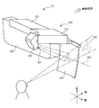
- FIG. 1 is a perspective view showing an aspect in which the head-up display 10 according to the present embodiment is observed from a field of view toward a windshield (not shown) of a vehicle from a room mirror 600 to which the head-up display 10 is attached.
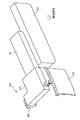
- FIG. 2 is a perspective view showing an aspect in which the head-up display 10 is observed with a field of view from the windshield (not shown) toward the room mirror 600.
- the front, rear, left, right, top, and bottom directions are the front and rear of the vehicle, the left side direction of the vehicle, the right side direction, and the vehicle from the plane perpendicular to the road surface on which the vehicle is disposed. Means the side direction and the opposite direction.
- the head-up display 10 generates an image signal related to an image displayed as a virtual image on the combiner 400, and stores a circuit board (not shown) that outputs the generated image signal to the optical unit 200. Is provided. An image signal output from an external device (not shown) such as a navigation device or a media playback device is input to the circuit board, and a predetermined process is performed on the input signal, which is then output to the optical unit 200. it can.
- the substrate storage unit 100 is connected to an attachment member (not shown), and the rearview mirror 600 is held by the attachment member, whereby the head-up display 10 is attached to the rearview mirror 600. Note that the mounting member is not shown for easy explanation and understanding of the overall configuration of the head-up display 10.
- the head-up display 10 includes an optical unit 200 to which an image signal output from a circuit board is input.
- the optical unit 200 includes an optical unit main body 210 and a projection unit 300.
- the optical unit main body 210 houses a light source, an image display element, various optical lenses, and the like which will be described later.
- the projection unit 300 houses various projection mirrors and an intermediate image screen described later.
- the image signal output from the circuit board is projected as image display light from the projection port to the combiner 400 having a concave shape via each device of the optical unit main body 210 and each device of the projection unit 300.
- LCOS Liquid crystal on silicon
- DMD Digital Micromirror Device
- the optical system and the driving circuit according to the display element to be applied are used.
- a laser type display device using MEMS Micro Electro Mechanical Systems or the like may be used.
- the user who is the driver recognizes the projected image display light as a virtual image via the combiner 400.
- the projection unit 300 projects the image display light of the character “A” onto the combiner 400.
- the user recognizes the letter “A” as if it is displayed, for example, 1.7m to 2.0m ahead (front of the vehicle) from the user, that is, recognizes the virtual image 450. it can.
- the central axis of the image display light projected from the projection unit 300 onto the combiner 400 is defined as the projection axis.
- FIG. 3 and 4 are diagrams for describing the internal configuration of the optical unit 200 of the head-up display 10 described above.
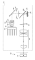
- FIG. 3 is a diagram showing an internal configuration of the optical unit main body 210 and a part of the internal configuration of the projection unit 300 together with an optical path related to image display light.
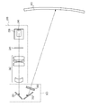
- FIG. 4 is a diagram illustrating an internal configuration of the projection unit 300 and a part of the internal configuration of the optical unit main body 210 together with an optical path related to image display light projected to the combiner 400.
- the optical unit body 210 includes a light source 231, a collimator lens 232, a UV-IR (Ultra Violet-Infrared Ray) cut filter 233, a polarizer 234, a fly-eye lens 235, a reflector 236, a field lens 237, and a wire grid polarization beam splitter 238. , A quarter wave plate 239, a phase compensation plate 241, a projection lens group 242, and a heat sink 243.
- the light source 231 includes a light emitting diode that emits light of three colors of white, blue, green, and red.
- a heat sink 243 is attached to the light source 231 for cooling the heat generated with light emission.
- the light emitted from the light source 231 is converted into parallel light by the collimating lens 232.
- the UV-IR cut filter 233 absorbs and removes ultraviolet light and infrared light from the parallel light that has passed through the collimating lens 232.
- the polarizer 234 changes the light that has passed through the UV-IR cut filter 233 into unpolarized P-polarized light.
- the fly-eye lens 235 uniformly adjusts the brightness of the light that has passed through the polarizer 234.
- the reflecting mirror 236 deflects the optical path of the light passing through each cell of the fly-eye lens 235 by 90 degrees.
- the light reflected by the reflecting mirror 236 is collected by the field lens 237.
- the light collected by the field lens 237 is irradiated to the image display element 240 via the wire grid polarization beam splitter 238 and the quarter wavelength plate 239 that transmit the P-polarized light.
- the image display element 240 includes red, green, and blue color filters for each pixel.
- the light emitted to the image display element 240 has a color corresponding to each pixel, is modulated by the liquid crystal composition included in the image display element 240, and becomes S-polarized image display light, which is applied to the wire grid polarization beam splitter 238. It is injected towards.
- the emitted S-polarized light is reflected by the wire grid polarization beam splitter 238, changes the optical path, passes through the phase compensation plate 241, and then enters the projection lens group 242.
- the image display light transmitted through the projection lens group 242 exits the optical unit main body 210 and enters the projection unit 300. And the 1st projection mirror 351 with which the projection part 300 is provided changes the optical path of the image display light which entered.
- the projection unit 300 includes a first projection mirror 351, a second projection mirror 352, and an intermediate image screen 360.
- the first projection mirror 351 and the second projection mirror 352 reflect the image display light projected through the wire grid polarization beam splitter 238, the phase compensation plate 241, and the projection lens group 242 included in the optical unit main body 210, and thereby the optical path thereof. Is deflected in the direction projected onto the combiner 400.
- the intermediate image screen 360 has a property of diffusing transmitted image display light at a predetermined light distribution angle.
- the intermediate image screen 360 for example, a diffusion plate having fine irregularities on the surface or a diffusion film in which a bead diffusion material having a diameter of about several tens of microns is distributed is used.
- the intermediate image screen 360 is provided at a position where a real image based on the image display light projected by the projection lens group 242 and reflected by the first projection mirror 351 and the second projection mirror 352 is formed. Accordingly, the image display light relating to the real image formed on the intermediate image screen 360 is transmitted while being diffused by the intermediate image screen 360, passes through the projection port 301, and is projected onto the combiner 400. The user recognizes a virtual image related to the image display light projected on the combiner 400 in the forward direction.
- the image display light diffused by the intermediate image screen 360 has a predetermined light distribution angle
- the image display light reflected by the combiner 400 and presented to the user also has a predetermined light distribution angle. Therefore, even when the user moves the line-of-sight position, the user can visually recognize the virtual image related to the image display light in a good state as long as it is within the light distribution angle range of the image display light reflected by the combiner 400. can do.
- the user can visually recognize a virtual image based on the image signal output from the circuit board superimposed on an actual landscape via the combiner 400. Further, even when the user moves the line-of-sight position, the intermediate image screen 360 has a property of diffusing transmitted light at a predetermined light distribution angle, so that the image display light with high visibility can be confirmed.
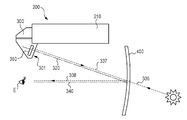
- FIG. 5 is a diagram for explaining extraneous light reflected by a conventional intermediate image screen 360, and extraneous light 336 such as sunlight is incident on the projection axis 320 of image display light projected from the projection unit 300.
- the state which injects along is shown.
- the image display light emitted from the projection port 301 reaches the combiner 400 along the projection axis 320, is reflected by the combiner 400, and reaches the user's eyes E along the line-of-sight direction 340.
- the extraneous light 336 incident along the projection axis 320 enters the projection port 301 of the projection unit 300 and reaches the intermediate image screen 360.
- a part of the extraneous light 336 reaching the intermediate image screen 360 is diffusely reflected by the intermediate image screen 360 and reaches the combiner 400 as extraneous light 337 having a predetermined light distribution angle.
- the extraneous light 338 reflected by the combiner 400 travels along the line-of-sight direction 340 and is visually recognized by the user.
- the extraneous light 338 reflected by the combiner 400 reaches the user's eyes E through the same path as the image display light projected from the projection unit 300, the user displays the image display light projected by the projection unit 300. Then, an image on which the extraneous light 338 is superimposed is visually recognized. Since the extraneous light 338 is diffusely reflected by the intermediate image screen 360 at a predetermined light distribution angle, the brightness of the incident extraneous light 336 is uniformly distributed and reaches the user's eyes E.
- an intermediate image screen 361 that can block the diffused and reflected external light 337 while maintaining the performance of diffusing the image display light projected by the projection unit 300 will be described.
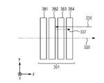
- FIG. 6 is a side view showing the configuration of the intermediate image screen 361 according to the embodiment.
- the intermediate image screen 361 includes a first wave plate 381, a polarization maintaining diffusion plate 382, a second wave plate 383, and an absorption polarizing plate 384.
- the first wave plate 381, the polarization-maintaining diffusing plate 382, the second wave plate 383, and the absorption-type polarizing plate 384 are provided in order so that the image display light emitted in the direction of the projection axis 320 is incident vertically.
- Each surface to be provided is provided in close proximity.
- the first wave plate 381, the polarization-maintaining diffusing plate 382, the second wave plate 383, and the absorption polarizing plate 384 may be provided so that their opposing surfaces are in contact with each other.
- the direction of the projection axis 320 from which the image display light is emitted is the z-axis direction
- the horizontal direction perpendicular to the z-axis direction is the x-axis direction
- the direction perpendicular to the z-axis direction and the x-axis direction is y.
- the image display light incident on the first wave plate 381 of the intermediate image screen 361 will be described as linearly polarized light whose electric field vibrates in the y direction.
- the first wave plate 381 is a quarter wave plate, and converts linearly polarized image display light emitted from the optical unit 200 and perpendicularly incident on the first wave plate 381 into circularly polarized image display light.
- the first wave plate 381 has a position in which the fast axis rotates 45 ° counterclockwise and the slow axis rotates 45 ° clockwise with respect to the y-axis direction. It is provided to become. Therefore, the y-polarized image display light incident on the first wave plate 381 is transmitted through the first wave plate 381 to become clockwise circularly-polarized image display light emitted in the + z direction.
- the polarization-maintaining diffusing plate 382 has a property of diffusing transmitted light at a predetermined light distribution angle while maintaining the polarization direction of the transmitted light, and a polymer with fine unevenness on the surface, fine unevenness It is comprised with the glass substrate etc. which provided diffusivity and provided.
- the processing for imparting diffusibility is performed on one side or both sides of the polarization maintaining diffusion plate 382.
- the clockwise circularly polarized image display light emitted from the first wavelength plate 381 is diffused and transmitted by the polarization maintaining diffusion plate 382 at a predetermined light distribution angle.
- the polarization state of the image display light diffused through the polarization-maintaining diffusion plate 382 is maintained, and right-handed circularly polarized image display light diffused at a predetermined light distribution angle is emitted from the polarization-maintaining diffusion plate 382. Is done.
- the second wave plate 383 is a quarter wave plate and is provided so as to convert the clockwise circularly polarized image display light diffused by the polarization maintaining diffusion plate 382 into linearly polarized image display light.
- the second wave plate 383 has a fast axis 45 ° counterclockwise with respect to the y-axis direction and a slow axis clockwise when viewed in the ⁇ z direction like the first wave plate 381. It is provided to be at a position rotated by 45 °. Therefore, clockwise circularly polarized image display light incident on the second wave plate 383 is transmitted through the second wave plate 383 and becomes linearly polarized light whose electric field vibrates in the x direction.
- the absorbing polarizing plate 384 is an absorbing polarizing plate that transmits light whose electric field vibrates in a certain direction and absorbs light whose electric field vibrates in a direction perpendicular to the transmitting vibration direction.
- the absorptive polarizing plate 384 is provided so that the transmission axis of the absorptive polarizing plate 384 is in the x-axis direction in order to transmit the x-polarized image display light emitted from the second wave plate 383. Therefore, the x-polarized image display light incident on the absorption type polarizing plate 384 is transmitted without being absorbed by the absorption type polarizing plate 384.
- the x-polarized image display light transmitted through the absorption type polarizing plate 384 is emitted from the projection port 301 of the projection unit 300 toward the combiner 400.
- Non-polarized extraneous light 336 incident from the projection port 301 of the projection unit 300 enters the absorption-type polarizing plate 384. Since the absorption-type polarizing plate 384 is provided so that the transmission axis is in the x-axis direction, the component that vibrates in the y-axis direction of the external light 336 is absorbed, and the component that vibrates in the x-axis direction is transmitted. Therefore, the external light 336 transmitted through the absorption type polarizing plate 384 becomes x-polarized light. Note that an antireflection film may be provided on the surface of the absorption polarizing plate 384 in order to prevent the extraneous light 336 from being reflected by the surface of the absorption polarizing plate 384.
- X-polarized extraneous light 336 transmitted through the absorption-type polarizing plate 384 enters the second wave plate 383.
- the second wave plate 383 is provided such that the fast axis rotates 45 ° counterclockwise and the slow axis rotates 45 ° clockwise with respect to the x axis. ing. Therefore, the x-polarized extraneous light 336 incident on the second wavelength plate 383 in the ⁇ z direction is transmitted through the second wavelength plate 383 and becomes clockwise circularly polarized light.
- the clockwise circularly polarized extraneous light 336 transmitted through the second wavelength plate 383 is incident on the polarization-maintaining diffusion plate 382, and a part of the light is diffusely reflected by the polarization-maintaining diffusion plate 382 while maintaining its polarization state. . Therefore, the clockwise circularly polarized extraneous light 336 incident in the ⁇ z direction is reflected by the polarization-maintaining diffusion plate 382 and becomes the counterclockwise circularly polarized extraneous light 337 emitted in the + z direction.
- the counterclockwise circularly polarized external light 337 reflected by the polarization-maintaining diffusion plate 382 is transmitted through the second wavelength plate 383 in the + z direction and becomes linearly polarized light whose electric field vibrates in the y direction.
- the y-polarized extraneous light 337 that has passed through the second wavelength plate 383 enters the absorption-type polarizing plate 384. Since the absorption-type polarizing plate 384 has a transmission axis in the x direction, the y-polarized extraneous light 337 is absorbed by the absorption-type polarizing plate 384 and does not pass therethrough.
- the image display light projected by the projection unit 300 can be projected through the projection port 301 after being diffused by the polarization maintaining diffusion plate 382 at a predetermined light distribution angle.
- the extraneous light 336 incident from the projection port 301 is diffusely reflected by the polarization-maintaining diffusing plate 382, it is absorbed by the absorption polarizing plate 384, and thus is not emitted in the direction of the projection axis 320 of the image display light. Therefore, it is possible to prevent the extraneous light 338 from reaching the user's eyes, and to suppress a decrease in contrast of the image display light presented to the user. Therefore, the user can visually recognize the image display light in a good state even in an environment illuminated by external light.
- the image display that transmits the absorption polarizing plate 384 is used compared to the case of using the diffusion plate that does not maintain the polarization state.
- the light can be brightened. If a diffusion plate that does not maintain the polarization state is used, the image display light that has passed through the diffusion plate contains components other than clockwise circularly polarized light. Therefore, the image display light that has passed through the second wavelength plate 383 is not x-polarized light. Contains ingredients. Components other than the x-polarized light are absorbed by the absorption polarizing plate 384, and the brightness of the image display light is reduced by the amount absorbed.
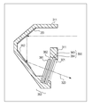
- FIG. 7 is a side sectional view showing the configuration of the projection unit 300 according to the embodiment.
- the intermediate image screen 361 is provided so as to block the projection port 301 of the projection unit 300, and is fixed to the projection unit 300 so that the surface thereof is perpendicular to the projection axis 320. Since the intermediate image screen 361 is provided so as to block the projection port 301, it is possible to prevent dust from entering the projection unit 300. Thereby, it is not necessary to separately provide a projection port cover for dust prevention, and the cost can be reduced.
- FIG. 8 is a side sectional view showing the configuration of the projection unit 311 according to the first modification. Unlike the projection unit 300 described above, the projection unit 311 according to the first modification includes an intermediate image screen 362 instead of the intermediate image screen 361.
- the intermediate image screen 362 according to the first modification is fixed to the projection unit 311 so that the polarization maintaining diffusion plate 382 and the second wavelength plate 383 are separated from each other.
- the second wave plate 383 and the absorption-type polarizing plate 384 are provided so as to close the projection port 301 of the projection unit 311 and serve as the projection port cover 390.
- the projection unit 311 causes the polarization maintaining diffusion plate 382 to diffuse the image display light at a predetermined light distribution angle and emit the image display light from the projection port 301 in the same manner as the projection unit 300.
- the extraneous light 336 incident from the projection port 301 is not emitted from the projection port 301 toward the projection axis 320 of the image display light. Therefore, even in an environment illuminated by external light, it is possible to present the image display light to the user in a good state.
- the projection port 301 is covered with the projection port cover 390, it is possible to prevent dust from entering the projection unit 311.
- the projection port 301 is dust-proof by the projection port cover 390, the first wavelength plate 381 and the polarization-maintaining diffusion plate 382 constituting the intermediate image screen 362 have an area smaller than the opening area of the projection port 301. be able to. Thereby, compared with the intermediate image screen 361 according to the embodiment, the cost of the intermediate image screen 362 according to the first modification can be reduced.
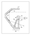
- FIG. 9 is a side sectional view showing the configuration of the projection unit 312 according to the second modification.
- the projection unit 312 according to the second modification includes a projection port cover 391 instead of the projection port cover 390.
- a projection port 302 in which a plane forming the projection port is not perpendicular to the projection axis 320 is provided.
- the projection port cover 391 includes a second wave plate 383 and an absorption-type polarizing plate 384, and is fixed to the projection unit 312 so that each surface intersects the projection axis 320 at a predetermined angle. The mouth 302 is blocked.
- the projection port cover 391 is provided in parallel with the plane that forms the projection port 302. Accordingly, the image display light diffused by the polarization-maintaining diffusion plate 382 is incident obliquely on the projection port cover 391 at a predetermined incident angle.
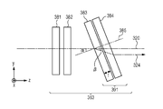
- FIG. 10 is a side view showing the configuration of the intermediate image screen 363 according to the second modification.
- the normal line 385 in FIG. 10 is an axis perpendicular to the surfaces that are the light incident surfaces of the second wave plate 383 and the absorption-type polarizing plate 384.
- the second wavelength plate 383 and the absorption type polarizing plate 384 constituting the projection port cover 391 are obliquely incident on the surface of the image display light emitted along the projection axis 320 at an incident angle ⁇ with respect to the normal line 385.
- the polarization-maintaining diffusing plate 382 is provided so that the diffused image display light is obliquely incident on the second wavelength plate 383 at an incident angle ⁇ .
- the image display light that is obliquely incident on the second wave plate 383 at the incident angle ⁇ is refracted on the surface of the second wave plate 383 and is transmitted through the second wave plate 383 at the refraction angle ⁇ .
- the distance that light passes through the second wave plate 383 is t / sin ⁇ , where t is the thickness of the second wave plate 383. Therefore, the thickness of the second wavelength plate 383 and the progress of the circularly polarized image display light obliquely incident on the second wavelength plate 383 become linearly polarized image display light when transmitted through a distance of t / sin ⁇ . Adjust the direction of the phase axis and slow axis.
- the image display light transmitted through the second wavelength plate 383 becomes x-polarized image display light.
- the x-polarized image display light emitted from the second wave plate 383 passes through the absorption polarizing plate 384 and is emitted as projection light 324 parallel to the projection axis 320.
- the projection unit 312 according to the second modification example can set the orientation of the plane forming the projection port 302 to an arbitrary angle, and increase the degree of freedom in designing the appearance of the projection unit 312. be able to.
- the projection port covers 390 and 391 are configured to include the second wave plate 383 and the absorption type polarizing plate 384, but the configuration is not limited thereto.
- the projection port covers 390 and 391 may include the absorption polarizing plate 384.
- the display apparatus for vehicles used attaching to other positions may be used.
- a projection unit is installed at the top of the dashboard of the vehicle or inside the dashboard, and a virtual image is presented to the user by projecting image display light onto a combiner provided between the windshield and the dashboard of the vehicle. May be.
- the description has been given as the vehicle display device disposed in the vehicle, but the image display device may be used for other purposes.
- a virtual surface may be presented to the user by using a lens surface such as glasses worn by the user as a combiner and projecting image display light onto the combiner.
- head-up display 200 optical unit, 240 image display element, 300, 311, 312 projection unit, 301, 302 projection port, 360, 361, 362, 363 intermediate image screen, 381 first wavelength plate, 382 polarization maintaining diffusion Plate, 383 second wavelength plate, 384 absorption polarizing plate, 400 combiner, 450 virtual image.
- an image display device capable of displaying an image with high visibility to the user even in an environment illuminated by external light.
Landscapes
- Physics & Mathematics (AREA)
- General Physics & Mathematics (AREA)
- Optics & Photonics (AREA)
- Engineering & Computer Science (AREA)
- Theoretical Computer Science (AREA)
- Business, Economics & Management (AREA)
- Marketing (AREA)
- Accounting & Taxation (AREA)
- Instrument Panels (AREA)
- Multimedia (AREA)
- Mechanical Engineering (AREA)
- Polarising Elements (AREA)
- Projection Apparatus (AREA)
Abstract
画像表示装置は、画像信号に基づいて画像表示光を生成する光学ユニットと、光学ユニットが生成した画像表示光を投射する投射部と、投射部から投射される画像表示光を反射して虚像を提示するコンバイナと、を備える。投射部は、画像表示素子から射出された直線偏光の画像表示光を、円偏光の画像表示光に変換する第1波長板(381)と、第1波長板(381)より射出された円偏光の画像表示光を拡散させる拡散板(382)と、拡散板(382)により拡散された円偏光の画像表示光を、直線偏光の画像表示光に変換する第2波長板(383)と、第2波長板(383)より射出された直線偏光の画像表示光を透過させる偏光板(384)と、を備える。
Description
本発明は、画像表示装置に関する。
ヘッドアップディスプレイと呼ばれる画像表示装置が知られている。ヘッドアップディスプレイはコンバイナと呼ばれる光学素子を有している。このコンバイナは、外来光を透過すると共に、ヘッドアップディスプレイが備える光学ユニットから投射された画像表示光を反射する。これによりユーザは、コンバイナを介して、画像表示光に係る画像を風景に重畳して視認することができる。
このヘッドアップディスプレイと呼ばれる画像表示装置によれば、車の運転者が、車外の景色を視認する視線方向や焦点位置をほとんど変化させることなく光学ユニットから投射された画像の情報をあわせて認識することができるため、車載用の画像表示装置として近年注目を集めている。
例えば特許文献1には、X軸ステージ、Z軸ステージ、及び回転ステージを用いることにより、ユーザが視認できる空間を調整する、車両のダッシュボードに搭載させるヘッドアップディスプレイが開示されている。
上述したようなヘッドアップディスプレイは、画像表示光に係る画像をコンバイナを介して風景に重畳して表示するため、外来光に照らされる環境下で用いる場合、外来光と比較して画像表示光のコントラストが相対的に低下し、ユーザの視認性に影響を及ぼすおそれがある。
本発明は上述の事情に鑑みてされたものであり、外来光に照らされる環境下においても、ユーザに視認性の高い画像を表示できる画像表示装置を提供することを目的とする。
上記課題を解決するために、本発明のある態様の画像表示装置は、画像信号に基づいて画像表示光を生成する光学ユニットと、光学ユニットが生成した画像表示光を投射する投射部と、投射部から投射される画像表示光を反射して虚像を提示するコンバイナと、を備え、投射部は、画像表示素子から射出された直線偏光の画像表示光を、円偏光の画像表示光に変換する第1波長板と、第1波長板より射出された円偏光の画像表示光を拡散させる拡散板と、拡散板により拡散された円偏光の画像表示光を、直線偏光の画像表示光に変換する第2波長板と、第2波長板より射出された直線偏光の画像表示光を透過させる偏光板と、を備える。
本発明によれば、外来光に照らされる環境下においても、ユーザに視認性の高い画像を表示できる画像表示装置を提供することができる。
以下、本発明の実施形態について、図面を参照しつつ説明する。かかる実施形態に示す具体的な数値等は、発明の理解を容易とするための例示にすぎず、特に断る場合を除き、本発明を限定するものではない。なお、本明細書及び図面において、実質的に同一の機能、構成を有する要素については、同一の符号を付することにより重複説明を省略し、また本発明に直接関係のない要素は図示を省略する。
本実施形態に係る車両用表示装置として、車両が備えるルームミラー(バックミラー)に取り付けられて使用されるヘッドアップディスプレイを例に挙げ、図1及び図2を参照して、その外観構成について説明する。図1は、本実施形態に係るヘッドアップディスプレイ10を、このヘッドアップディスプレイ10が取り付けられたルームミラー600から車両の図示しないウィンドシールドの方に向かう視野により観察した態様を示す斜視図である。また図2は、同じく図示しないウィンドシールドからルームミラー600の方に向かう視野により、ヘッドアップディスプレイ10を観察した態様を示す斜視図である。以後の説明において、前、後、左、右及び上、下で示される方向は、それぞれ車両の前方、後方、車両の左側方向、右側方向、車両が配置された路面に垂直で当該面から車両側の方向及びその反対方向を意味する。
ヘッドアップディスプレイ10は、コンバイナ400に虚像として表示される画像に係る画像信号を生成し、その生成された画像信号を光学ユニット200に出力する回路基板(不図示)が収納された基板収納部100を備える。回路基板は、ナビゲーション装置やメディア再生装置などの図示しない外部装置から出力された画像信号が入力され、その入力された信号に対して所定の処理を行った後、光学ユニット200に出力することもできる。この基板収納部100が、図示しない取付部材と連結され、ルームミラー600が取付部材に保持されることで、ヘッドアップディスプレイ10がルームミラー600に取り付けられる。なお、取付部材はヘッドアップディスプレイ10の全体構成の説明及び理解の容易のため、記載を省略している。
ヘッドアップディスプレイ10は、回路基板から出力された画像信号が入力される光学ユニット200を備える。光学ユニット200は、光学ユニット本体210、及び投射部300を備える。光学ユニット本体210には、後述する光源、画像表示素子、及び各種光学レンズなどが収納される。投射部300には、後述する各種投射ミラー及び中間像スクリーンが収納される。回路基板が出力した画像信号は、光学ユニット本体210の上記各デバイス、及び投射部300の上記各デバイスを介して、投射口から凹面形状を有するコンバイナ400に画像表示光として投射される。
なお、本実施形態では画像表示素子として反射型液晶表示パネルであるLCOS(Liquid crystal on silicon)を用いる場合を例示するが、画像表示素子240としてDMD(Digital Micromirror Device)を用いてもよい。その場合、適用する表示素子に応じた光学系及び駆動回路で構成するものとする。また、MEMS(Micro Electro Mechanical Systems)等を用いたレーザ型の表示装置であってもよい。
運転者であるユーザは投射された画像表示光をコンバイナ400を介して虚像として認識する。図1では、投射部300が「A」の文字の画像表示光をコンバイナ400に投射している。ユーザはコンバイナ400を見ることで、「A」の文字が、ユーザから例えば1.7m~2.0m前方(車両前方)に表示されているかのように認識する、すなわち虚像450を認識することができる。ここで、投射部300からコンバイナ400に投射される画像表示光の中心軸を投射軸と定義する。
次にヘッドアップディスプレイ10の内部構成について説明する。図3及び図4は、上述したヘッドアップディスプレイ10の光学ユニット200の内部構成について説明するための図である。図3は光学ユニット本体210の内部構成、及び投射部300の内部構成の一部を画像表示光に係る光路とともに示す図である。図4は投射部300の内部構成、及び光学ユニット本体210の内部構成の一部を、コンバイナ400まで投射される画像表示光に係る光路とともに示す図である。
まず図3を参照して光学ユニット本体210の内部構成及び画像表示光に係る光路について説明する。光学ユニット本体210は、光源231、コリメートレンズ232、UV-IR(Ultra Violet-Infrared Ray)カットフィルタ233、偏光子234、フライアイレンズ235、反射鏡236、フィールドレンズ237、ワイヤーグリッド偏光ビームスプリッタ238、1/4波長板239、位相補償板241、投射レンズ群242、及びヒートシンク243を備える。
光源231は白色、又は青色、緑色、及び赤色の三色の光を発する発光ダイオードからなる。光源231には発光に伴い発生する熱を放冷するためのヒートシンク243が取り付けられている。光源231が発光した光は、コリメートレンズ232によって平行光に変えられる。UV-IRカットフィルタ233は、コリメートレンズ232を通過した平行光から紫外光及び赤外光を吸収し除去する。偏光子234は、UV-IRカットフィルタ233を通過した光を乱れのないP偏光へと変える。そしてフライアイレンズ235が、偏光子234を通過した光の明るさを均一に整える。
反射鏡236は、フライアイレンズ235の各セルを通過した光の光路を90度偏向する。反射鏡236で反射された光はフィールドレンズ237によって集光される。フィールドレンズ237が集光した光は、P偏光を透過するワイヤーグリッド偏光ビームスプリッタ238及び1/4波長板239を介して、画像表示素子240に照射される。
画像表示素子240は、画素毎に赤色、緑色、及び青色のカラーフィルタを備えている。画像表示素子240に照射された光は、各画素に対応する色となり、画像表示素子240の備える液晶組成物によって変調が施され、S偏光の画像表示光となってワイヤーグリッド偏光ビームスプリッタ238に向けて射出される。射出されたS偏光の光はワイヤーグリッド偏光ビームスプリッタ238で反射され、光路を変えて位相補償板241を通過した後に投射レンズ群242へ入射される。
投射レンズ群242を透過した画像表示光は、光学ユニット本体210を出て投射部300に入る。そして投射部300が備える第1投射ミラー351が、入ってきた画像表示光の光路を変更する。
次に図4を参照して投射部300の内部構成及び画像表示光に係る光路について説明する。投射部300は、第1投射ミラー351、第2投射ミラー352、及び中間像スクリーン360を備える。
第1投射ミラー351及び第2投射ミラー352は、光学ユニット本体210の備えるワイヤーグリッド偏光ビームスプリッタ238、位相補償板241、投射レンズ群242を通じて投射された画像表示光を反射することにより、その光路をコンバイナ400へ投射される向きに偏向する。
中間像スクリーン360は、透過する画像表示光を所定の配光角で拡散させる性質を有する。中間像スクリーン360として、例えば、表面に微細な凹凸を設けた拡散板や、直径数十ミクロン程度のビーズ拡散材を分布させた拡散フィルムなどを用いる。また、中間像スクリーン360は、投射レンズ群242により投射され、第1投射ミラー351及び第2投射ミラー352で反射された画像表示光に基づく実像が結像する位置に設けられる。したがって、中間像スクリーン360に結像した実像に係る画像表示光は、中間像スクリーン360により拡散されながら透過し、投射口301を通過してコンバイナ400に投射される。ユーザは、コンバイナ400に投射された画像表示光に係る虚像を前方に認識することになる。
このとき、中間像スクリーン360により拡散された画像表示光は所定の配光角を有し、コンバイナ400により反射されユーザに提示される画像表示光も所定の配光角を有する。そのため、ユーザは、その視線位置を移動させた場合であっても、コンバイナ400により反射される画像表示光の配光角の範囲内であれば、画像表示光に係る虚像を良好な状態で視認することができる。
以上の内部構成により、ユーザは、回路基板から出力された画像信号に基づく虚像を、コンバイナ400を介して現実の風景に重畳して視認することができる。また、ユーザは、視線位置を移動させたとしても、中間像スクリーン360が所定の配光角で透過光を拡散させる性質を有することにより、視認性の高い画像表示光を確認することができる。
一方で、上述の中間像スクリーン360を設けることにより、外来光が中間像スクリーン360に入射し拡散反射されることで、画像表示光のコントラストが低下してしまうことがある。まず、図5を用いて本発明が解決しようとする画像表示光のコントラストの低下について説明し、図6以降を用いて本発明の実施形態に係る中間像スクリーン360について説明する。
図5は、従来の中間像スクリーン360にて反射される外来光を説明するための図であり、太陽光などの外来光336が、投射部300から投射される画像表示光の投射軸320に沿って入射している状態を示している。投射口301から射出された画像表示光は、投射軸320に沿ってコンバイナ400に達し、コンバイナ400により反射され、視線方向340に沿ってユーザの目Eに到達する。一方、投射軸320に沿って入射してくる外来光336は、投射部300の投射口301に入射し、中間像スクリーン360に達する。中間像スクリーン360に達した外来光336の一部は、中間像スクリーン360により拡散反射されて、所定の配光角を有する外来光337としてコンバイナ400に達する。コンバイナ400により反射された外来光338は、視線方向340に沿って進みユーザに視認される。
このとき、コンバイナ400により反射された外来光338は、投射部300から投射される画像表示光と同じ経路を通ってユーザの目Eに達するため、ユーザは、投射部300が投射した画像表示光と、外来光338とが重畳した画像を視認することとなる。外来光338は、中間像スクリーン360により所定の配光角で拡散反射されているため、入射してきた外来光336の明るさが一様に分布した状態となって、ユーザの目Eに達する。そうすると、ユーザは、明るく分布した外来光338とともに投射部300が投射した画像表示光を視認することとなり、外来光338がない場合と比べてユーザに提示する画像表示光のコントラストが低下する。画像表示光のコントラストが低下すると、ユーザは良好な状態で画像表示光を視認することができない。
そこで、本実施形態に係る中間像スクリーン361として、投射部300が投射する画像表示光を拡散させる性能は維持したまま、拡散反射される外来光337を遮断できる中間像スクリーン361について述べる。
図6は、実施形態に係る中間像スクリーン361の構成を示す側面図である。中間像スクリーン361は、第1波長板381と、偏光保持型拡散板382と、第2波長板383と、吸収型偏光板384とを備える。第1波長板381、偏光保持型拡散板382、第2波長板383、吸収型偏光板384は、投射軸320の方向に射出される画像表示光が垂直に入射するようそれぞれ順に設けられ、対向するそれぞれの面が近接して設けられている。なお、第1波長板381、偏光保持型拡散板382、第2波長板383、吸収型偏光板384は、対向するそれぞれの面が接するように設けられていてもよい。
なお、図6において、画像表示光が射出される投射軸320の方向をz軸方向とし、z軸方向に垂直な水平方向をx軸方向、z軸方向およびx軸方向に垂直な方向をy軸方向とする。また、中間像スクリーン361の第1波長板381に入射する画像表示光は、y方向に電場が振動する直線偏光として説明する。
第1波長板381は、1/4波長板であり、光学ユニット200から射出され第1波長板381に垂直に入射する直線偏光の画像表示光を、円偏光の画像表示光に変換するように設けられる。例えば、第1波長板381は、-z方向に向かって見た場合に、y軸方向に対して進相軸が反時計回りに45°、遅相軸が時計回りに45°回転した位置となるように設けられる。したがって、第1波長板381に入射したy偏光の画像表示光は、第1波長板381を透過することにより、+z方向に射出される右回り円偏光の画像表示光となる。
偏光保持型拡散板382は、透過する光の偏光方向を維持したまま所定の配光角で透過光を拡散させる性質を有し、表面に微細な凹凸加工を施されたポリマーや、微細な凹凸を設けて拡散性を持たせたガラス基板などにより構成される。なお、拡散性を持たせるための加工は、偏光保持型拡散板382の片面もしくは両面になされる。第1波長板381より射出された右回り円偏光の画像表示光は、偏光保持型拡散板382により所定の配光角で拡散され透過する。偏光保持型拡散板382を透過して拡散された画像表示光の偏光状態は保持され、偏光保持型拡散板382からは、所定の配光角で拡散した右回り円偏光の画像表示光が射出される。
第2波長板383は、1/4波長板であり、偏光保持型拡散板382により拡散された右回り円偏光の画像表示光を、直線偏光の画像表示光に変換するように設けられる。例えば、第2波長板383は、第1波長板381と同様-z方向に向かって見た場合に、y軸方向に対して進相軸が反時計回りに45°、遅相軸が時計回りに45°回転した位置となるように設けられる。したがって、第2波長板383に入射した右回り円偏光の画像表示光は、第2波長板383を透過することにより、x方向に電場が振動する直線偏光となる。
吸収型偏光板384は、ある方向に電場が振動する光を透過させ、透過させる振動方向に垂直な方向に電場が振動する光を吸収する吸収型の偏光板である。吸収型偏光板384は第2波長板383から射出されたx偏光の画像表示光を透過させるため、吸収型偏光板384の透過軸がx軸方向となるように設けられる。したがって、吸収型偏光板384に入射したx偏光の画像表示光は、吸収型偏光板384に吸収されずにそのまま透過する。吸収型偏光板384を透過したx偏光の画像表示光は、投射部300の投射口301からコンバイナ400に向けて射出される。
次に、図6の中間像スクリーン361に入射する外来光336について述べる。投射部300の投射口301から入射した無偏光の外来光336は、吸収型偏光板384に入射する。吸収型偏光板384は、透過軸がx軸方向となるように設けられているため、外来光336のy軸方向に振動する成分は吸収され、x軸方向に振動する成分が透過する。したがって、吸収型偏光板384を透過した外来光336は、x偏光となる。なお、吸収型偏光板384の表面には、外来光336が吸収型偏光板384の表面で反射されるのを防止するため、反射防止膜が設けられてもよい。
吸収型偏光板384を透過したx偏光の外来光336は、第2波長板383に入射する。第2波長板383は、+z方向に向かって見た場合、x軸に対して進相軸が反時計回りに45°、遅相軸が時計回りに45°回転した位置となるように設けられている。したがって、第2波長板383に-z方向に入射したx偏光の外来光336は、第2波長板383を透過することにより、右回り円偏光となる。
第2波長板383を透過した右回り円偏光の外来光336は、偏光保持型拡散板382に入射し、偏光保持型拡散板382によってその一部がその偏光状態を保持したまま拡散反射される。したがって、-z方向に入射した右回り円偏光の外来光336は、偏光保持型拡散板382で反射し、+z方向に射出する左回り円偏光の外来光337となる。
偏光保持型拡散板382で反射された左回り円偏光の外来光337は、第2波長板383を+z方向に透過し、y方向に電場が振動する直線偏光となる。第2波長板383を透過したy偏光の外来光337は、吸収型偏光板384に入射する。吸収型偏光板384は、透過軸がx方向であるため、y偏光の外来光337は吸収型偏光板384に吸収され、透過しない。
以上の構成により、投射部300が投射する画像表示光は偏光保持型拡散板382により所定の配光角で拡散させた後、投射口301を介して投射することができる。一方、投射口301から入射した外来光336は、偏光保持型拡散板382により拡散反射されたとしても吸収型偏光板384に吸収されるため、画像表示光の投射軸320方向に射出されない。したがって、ユーザの目に、外来光338が達することを防ぐことができ、ユーザに提示する画像表示光のコントラスト低下を抑えることができる。よってユーザは、外来光に照らされる環境下においても、良好な状態で画像表示光を視認することができる。
また、偏光状態を保持したまま画像表示光を拡散させる偏光保持型拡散板382を用いることで、偏光状態を保持しない拡散板を用いる場合と比較して、吸収型偏光板384を透過する画像表示光を明るくすることができる。仮に、偏光状態を保持しない拡散板を用いると、拡散板を透過した画像表示光は右回り円偏光以外の成分を含むため、第2波長板383を透過した画像表示光は、x偏光以外の成分を含む。x偏光以外の成分は吸収型偏光板384により吸収され、吸収された分だけ画像表示光の明るさが低下してしまう。
図7は、実施形態に係る投射部300の構成を示す側面断面図である。中間像スクリーン361は、投射部300の投射口301を塞ぐように設けられ、その表面が投射軸320と垂直となるように投射部300に固定される。中間像スクリーン361は、投射口301を塞ぐように設けられるため、投射部300の内部への塵の侵入を防ぐこともできる。これにより、防塵のための投射口カバーを別途設ける必要がなくなり、コストを低減させることができる。
以上、本発明を実施の形態をもとに説明した。実施の形態は例示であり、それらの各構成要素や各処理プロセスの組合せにいろいろな変形例が可能なこと、またそうした変形例も本発明の範囲にあることは当業者に理解されるところである。
図8は、第1の変形例に係る投射部311の構成を示す側面断面図である。第1の変形例に係る投射部311は、上述の投射部300とは異なり、中間像スクリーン361の代わりに、中間像スクリーン362を備える。
第1の変形例に係る中間像スクリーン362は、中間像スクリーン361とは異なり、偏光保持型拡散板382と第2波長板383との間が離隔するようにして投射部311に固定されている。また、第2波長板383と吸収型偏光板384は、投射部311の投射口301を塞ぐように設けられており、投射口カバー390としての役割を持つ。
以上の構成により、第1の変形例に係る投射部311は、投射部300と同様に、偏光保持型拡散板382により画像表示光を所定の配光角で拡散させて投射口301から射出させる一方、投射口301から入射した外来光336は、投射口301から画像表示光の投射軸320方向に射出させない。よって、外来光に照らされる環境下においても、ユーザに良好な状態で画像表示光を提示することができる。
また、投射口301は、投射口カバー390により覆われているため、投射部311内部への塵の侵入を防ぐことができる。このとき、投射口301は投射口カバー390により防塵されるため、中間像スクリーン362を構成する第1波長板381と偏光保持型拡散板382は、投射口301の開口面積よりも小さい面積とすることができる。これにより、実施形態に係る中間像スクリーン361と比較して、第1の変形例に係る中間像スクリーン362のコストを低減させることができる。
図9は、第2の変形例に係る投射部312の構成を示す側面断面図である。第2の変形例に係る投射部312は、第1の変形例に係る投射部311と異なり、投射口カバー390の代わりに、投射口カバー391を備える。また、投射口301の代わりに、投射口を形成する平面が投射軸320と垂直とならない投射口302を備える。
第2の変形例に係る投射口カバー391は、第2波長板383と吸収型偏光板384を備え、それぞれの表面が投射軸320と所定の角度で交わるように投射部312に固定され、投射口302を塞いでいる。投射口カバー391は、投射口302を形成する平面と平行に設けられている。したがって、偏光保持型拡散板382で拡散された画像表示光は、投射口カバー391に対して所定の入射角で斜入射する。
図10は、第2の変形例に係る中間像スクリーン363の構成を示す側面図である。図10の法線385は、第2波長板383および吸収型偏光板384の光入射面である表面と垂直な軸である。投射口カバー391を構成する第2波長板383と吸収型偏光板384は、投射軸320に沿って射出される画像表示光が、法線385に対して入射角αでその表面に斜入射する位置に設けられている。偏光保持型拡散板382は、拡散させた画像表示光が第2波長板383に入射角αで斜入射するように設けられる。
このとき、第2波長板383に入射角αで斜入射する画像表示光は、第2波長板383の表面で屈折され、屈折角βの角度で第2波長板383を透過するため、画像表示光が第2波長板383を透過する距離は、第2波長板383の板厚をtとすると、t/sinβとなる。そこで、第2波長板383に斜入射する円偏光の画像表示光が、t/sinβの距離を透過した場合に直線偏光の画像表示光となるよう、第2波長板383の板厚や、進相軸および遅相軸の向きを調整する。これにより、第2波長板383を透過した画像表示光は、x偏光の画像表示光となる。その後、第2波長板383から射出したx偏光の画像表示光は吸収型偏光板384を透過し、投射軸320と平行な投射光324として射出される。
以上の構成とすることにより、第2の変形例に係る投射部312は、投射口302を形成する平面の向きを任意の角度とすることができ、投射部312の外観の設計自由度を上げることができる。
なお、上述の第1および第2の変形例においては、投射口カバー390、391が第2波長板383と吸収型偏光板384を備える構成としたが、その構成はこれに限らない。例えば、投射口カバー390、391が吸収型偏光板384を備える構成としてもよい。
また、上述の実施形態および変形例においては、車両用表示装置として車両が備えるルームミラーに取り付けて使用される場合を説明したが、その他の位置に取り付けて用いる車両用表示装置であってもよい。例えば、車両のダッシュボードの上部や、ダッシュボード内部に投射部が設置され、車両のウィンドシールドとダッシュボードとの間に設けられるコンバイナに画像表示光を投射することにより、ユーザに虚像を提示してもよい。
また、上述の実施形態においては、車両に配置する車両用表示装置として説明を行ったが、その他の用途に用いる画像表示装置であってもよい。例えば、ユーザが身につける眼鏡等のレンズ面をコンバイナとして用い、そのコンバイナに画像表示光を投射することにより、ユーザに虚像を提示してもよい。
10 ヘッドアップディスプレイ、 200 光学ユニット、 240 画像表示素子、 300、311、312 投射部、 301、302 投射口、 360、361、362、363 中間像スクリーン、 381 第1波長板、 382 偏光保持型拡散板、 383 第2波長板、384 吸収型偏光板、 400 コンバイナ、 450 虚像。
本発明によれば、外来光に照らされる環境下においても、ユーザに視認性の高い画像を表示できる画像表示装置を提供することができる。
Claims (4)
- 画像信号に基づいて画像表示光を生成する光学ユニットと、
前記光学ユニットが生成した画像表示光を投射する投射部と、
前記投射部から投射される画像表示光を反射して虚像を提示するコンバイナと、
を備え、
前記投射部は、
画像表示素子から射出された直線偏光の画像表示光を、円偏光の画像表示光に変換する第1波長板と、
前記第1波長板より射出された円偏光の画像表示光を拡散させる拡散板と、
前記拡散板により拡散された円偏光の画像表示光を、直線偏光の画像表示光に変換する第2波長板と、
前記第2波長板より射出された直線偏光の画像表示光を透過させる偏光板と、
を備えることを特徴とする画像表示装置。 - 前記偏光板は、前記投射部の投射口を塞ぐように配置されることを特徴とする請求項1に記載の画像表示装置。
- 前記第2波長板は、前記投射部の投射口を形成する平面と平行に設けられ、
前記拡散板は、拡散させた円偏光の画像表示光が、前記第2波長板に対して所定の入射角で斜入射するように設けられ、
前記第2波長板は、前記所定の入射角で斜入射した円偏光の画像表示光を直線偏光に変換して射出させることを特徴とする請求項1または2に記載の画像表示装置。 - 前記拡散板は、前記拡散板へ入射する画像表示光の偏光状態を維持したまま、前記画像表示光を拡散させる偏光保持型拡散板であることを特徴とする請求項1から3のいずれかに記載の画像表示装置。
Priority Applications (1)
| Application Number | Priority Date | Filing Date | Title |
|---|---|---|---|
| US14/597,683 US9580015B2 (en) | 2012-07-30 | 2015-01-15 | Image display device |
Applications Claiming Priority (2)
| Application Number | Priority Date | Filing Date | Title |
|---|---|---|---|
| JP2012168937A JP6056246B2 (ja) | 2012-07-30 | 2012-07-30 | 画像表示装置 |
| JP2012-168937 | 2012-07-30 |
Related Child Applications (1)
| Application Number | Title | Priority Date | Filing Date |
|---|---|---|---|
| US14/597,683 Continuation US9580015B2 (en) | 2012-07-30 | 2015-01-15 | Image display device |
Publications (1)
| Publication Number | Publication Date |
|---|---|
| WO2014020858A1 true WO2014020858A1 (ja) | 2014-02-06 |
Family
ID=50027567
Family Applications (1)
| Application Number | Title | Priority Date | Filing Date |
|---|---|---|---|
| PCT/JP2013/004469 Ceased WO2014020858A1 (ja) | 2012-07-30 | 2013-07-23 | 画像表示装置 |
Country Status (3)
| Country | Link |
|---|---|
| US (1) | US9580015B2 (ja) |
| JP (1) | JP6056246B2 (ja) |
| WO (1) | WO2014020858A1 (ja) |
Families Citing this family (13)
| Publication number | Priority date | Publication date | Assignee | Title |
|---|---|---|---|---|
| FR3029353B1 (fr) * | 2014-11-28 | 2016-12-23 | Valeo Comfort & Driving Assistance | Dispositif de retroeclairage notamment pour afficheur tete haute et afficheur tete haute pour vehicule automobile |
| JP6372346B2 (ja) * | 2014-12-24 | 2018-08-15 | 日本精機株式会社 | ヘッドアップディスプレイ |
| WO2016171154A1 (ja) * | 2015-04-24 | 2016-10-27 | シャープ株式会社 | 表示装置 |
| KR101872089B1 (ko) * | 2016-02-12 | 2018-07-31 | 엘지전자 주식회사 | 차량용 헤드 업 디스플레이 |
| JP6595250B2 (ja) * | 2015-08-06 | 2019-10-23 | 株式会社ポラテクノ | ヘッドアップディスプレイ装置 |
| JPWO2017061000A1 (ja) * | 2015-10-08 | 2018-06-28 | マクセル株式会社 | ヘッドアップディスプレイ装置 |
| DE102016225718B4 (de) * | 2015-12-29 | 2021-12-23 | Ford Global Technologies, Llc | Head-up-Display für ein Fahrzeug sowie ein Fahrzeug |
| US10018840B2 (en) * | 2016-02-12 | 2018-07-10 | Lg Electronics Inc. | Head up display for vehicle |
| CN107479193B (zh) * | 2016-06-08 | 2020-02-21 | 深圳市掌网科技股份有限公司 | 一种用于头戴式显示器的防尘结构 |
| DE102016213687B4 (de) * | 2016-07-26 | 2019-02-07 | Audi Ag | Verfahren zum Steuern einer Anzeigevorrichtung für ein Kraftfahrzeug, Anzeigevorrichtung für ein Kraftfahrzeug und Kraftfahrzeug mit einer Anzeigevorrichtung |
| JP6572856B2 (ja) * | 2016-09-22 | 2019-09-11 | 株式会社デンソー | ヘッドアップディスプレイ装置 |
| CN115616775A (zh) * | 2021-07-16 | 2023-01-17 | 中强光电股份有限公司 | 抬头显示器 |
| EP4120004B1 (en) | 2021-07-16 | 2024-11-06 | Coretronic Corporation | Head up display |
Citations (3)
| Publication number | Priority date | Publication date | Assignee | Title |
|---|---|---|---|---|
| JPH07230059A (ja) * | 1994-02-17 | 1995-08-29 | Nippondenso Co Ltd | ホログラム表示装置 |
| JP2005274955A (ja) * | 2004-03-24 | 2005-10-06 | Tatsuo Uchida | リアプロジェクションディスプレイ用光学系 |
| JP2007186016A (ja) * | 2006-01-11 | 2007-07-26 | Denso Corp | 車両用ヘッドアップディスプレイ装置 |
Family Cites Families (3)
| Publication number | Priority date | Publication date | Assignee | Title |
|---|---|---|---|---|
| JPH10278629A (ja) | 1997-04-08 | 1998-10-20 | Toppan Printing Co Ltd | 車両用ヘッドアップディスプレイ装置 |
| WO2005022238A1 (ja) * | 2003-09-01 | 2005-03-10 | Nikon Corporation | 画像表示装置およびカメラ |
| TW201207442A (en) * | 2009-12-25 | 2012-02-16 | Mitsui Chemicals Inc | Polarizing diffusion film, method for fabricating the same, and liquid crystal display apparatus including the same |
-
2012
- 2012-07-30 JP JP2012168937A patent/JP6056246B2/ja active Active
-
2013
- 2013-07-23 WO PCT/JP2013/004469 patent/WO2014020858A1/ja not_active Ceased
-
2015
- 2015-01-15 US US14/597,683 patent/US9580015B2/en active Active
Patent Citations (3)
| Publication number | Priority date | Publication date | Assignee | Title |
|---|---|---|---|---|
| JPH07230059A (ja) * | 1994-02-17 | 1995-08-29 | Nippondenso Co Ltd | ホログラム表示装置 |
| JP2005274955A (ja) * | 2004-03-24 | 2005-10-06 | Tatsuo Uchida | リアプロジェクションディスプレイ用光学系 |
| JP2007186016A (ja) * | 2006-01-11 | 2007-07-26 | Denso Corp | 車両用ヘッドアップディスプレイ装置 |
Also Published As
| Publication number | Publication date |
|---|---|
| JP6056246B2 (ja) | 2017-01-11 |
| JP2014026245A (ja) | 2014-02-06 |
| US9580015B2 (en) | 2017-02-28 |
| US20150123879A1 (en) | 2015-05-07 |
Similar Documents
| Publication | Publication Date | Title |
|---|---|---|
| JP6056246B2 (ja) | 画像表示装置 | |
| JP6115420B2 (ja) | 画像表示装置 | |
| CN105874358B (zh) | 透射型屏幕及使用了它的图像显示装置 | |
| TWI604225B (zh) | 抬頭顯示器光學架構 | |
| JP2018049294A (ja) | 中間像形成部 | |
| JP6127912B2 (ja) | 画像表示装置 | |
| JPWO2016147570A1 (ja) | ヘッドアップディスプレイ | |
| JP5953987B2 (ja) | 画像表示装置 | |
| JPWO2015159523A1 (ja) | ヘッドアップディスプレイ、およびヘッドアップディスプレイを搭載した移動体 | |
| US10578867B2 (en) | Head-up display with holographic optical element | |
| JP2015034918A (ja) | 画像表示方法、画像表示装置、偏光スクリーンならびに偏光板 | |
| WO2019077939A1 (ja) | 虚像表示装置 | |
| JP2024007661A (ja) | ヘッドアップディスプレイ装置 | |
| JP5906968B2 (ja) | 車両用表示装置 | |
| JP6683149B2 (ja) | ヘッドアップディスプレイ装置 | |
| JP6330944B2 (ja) | 中間像形成装置 | |
| JP5910394B2 (ja) | 画像表示装置 | |
| JP2024179345A (ja) | ヘッドアップディスプレイ及び乗り物 | |
| JP2023057027A (ja) | 画像生成ユニット及びヘッドアップディスプレイ装置 | |
| JP2025116913A (ja) | ヘッドアップディスプレイ | |
| JP2019211718A (ja) | 虚像表示装置 | |
| WO2016162922A1 (ja) | ヘッドアップディスプレイ |
Legal Events
| Date | Code | Title | Description |
|---|---|---|---|
| 121 | Ep: the epo has been informed by wipo that ep was designated in this application |
Ref document number: 13824762 Country of ref document: EP Kind code of ref document: A1 |
|
| NENP | Non-entry into the national phase |
Ref country code: DE |
|
| 122 | Ep: pct application non-entry in european phase |
Ref document number: 13824762 Country of ref document: EP Kind code of ref document: A1 |