WO2014017649A1 - 回転コネクタ装置 - Google Patents
回転コネクタ装置 Download PDFInfo
- Publication number
- WO2014017649A1 WO2014017649A1 PCT/JP2013/070371 JP2013070371W WO2014017649A1 WO 2014017649 A1 WO2014017649 A1 WO 2014017649A1 JP 2013070371 W JP2013070371 W JP 2013070371W WO 2014017649 A1 WO2014017649 A1 WO 2014017649A1
- Authority
- WO
- WIPO (PCT)
- Prior art keywords
- flat cable
- conductor
- cable
- signal
- dummy
- Prior art date
- Legal status (The legal status is an assumption and is not a legal conclusion. Google has not performed a legal analysis and makes no representation as to the accuracy of the status listed.)
- Ceased
Links
Images


Classifications
-
- H—ELECTRICITY
- H01—ELECTRIC ELEMENTS
- H01R—ELECTRICALLY-CONDUCTIVE CONNECTIONS; STRUCTURAL ASSOCIATIONS OF A PLURALITY OF MUTUALLY-INSULATED ELECTRICAL CONNECTING ELEMENTS; COUPLING DEVICES; CURRENT COLLECTORS
- H01R35/00—Flexible or turnable line connectors, i.e. the rotation angle being limited
- H01R35/04—Turnable line connectors with limited rotation angle with frictional contact members
-
- H—ELECTRICITY
- H01—ELECTRIC ELEMENTS
- H01R—ELECTRICALLY-CONDUCTIVE CONNECTIONS; STRUCTURAL ASSOCIATIONS OF A PLURALITY OF MUTUALLY-INSULATED ELECTRICAL CONNECTING ELEMENTS; COUPLING DEVICES; CURRENT COLLECTORS
- H01R35/00—Flexible or turnable line connectors, i.e. the rotation angle being limited
- H01R35/02—Flexible line connectors without frictional contact members
- H01R35/025—Flexible line connectors without frictional contact members having a flexible conductor wound around a rotation axis
-
- B—PERFORMING OPERATIONS; TRANSPORTING
- B60—VEHICLES IN GENERAL
- B60R—VEHICLES, VEHICLE FITTINGS, OR VEHICLE PARTS, NOT OTHERWISE PROVIDED FOR
- B60R16/00—Electric or fluid circuits specially adapted for vehicles and not otherwise provided for; Arrangement of elements of electric or fluid circuits specially adapted for vehicles and not otherwise provided for
- B60R16/02—Electric or fluid circuits specially adapted for vehicles and not otherwise provided for; Arrangement of elements of electric or fluid circuits specially adapted for vehicles and not otherwise provided for electric constitutive elements
- B60R16/0207—Wire harnesses
- B60R16/0215—Protecting, fastening and routing means therefor
-
- B—PERFORMING OPERATIONS; TRANSPORTING
- B60—VEHICLES IN GENERAL
- B60R—VEHICLES, VEHICLE FITTINGS, OR VEHICLE PARTS, NOT OTHERWISE PROVIDED FOR
- B60R16/00—Electric or fluid circuits specially adapted for vehicles and not otherwise provided for; Arrangement of elements of electric or fluid circuits specially adapted for vehicles and not otherwise provided for
- B60R16/02—Electric or fluid circuits specially adapted for vehicles and not otherwise provided for; Arrangement of elements of electric or fluid circuits specially adapted for vehicles and not otherwise provided for electric constitutive elements
- B60R16/023—Electric or fluid circuits specially adapted for vehicles and not otherwise provided for; Arrangement of elements of electric or fluid circuits specially adapted for vehicles and not otherwise provided for electric constitutive elements for transmission of signals between vehicle parts or subsystems
- B60R16/027—Electric or fluid circuits specially adapted for vehicles and not otherwise provided for; Arrangement of elements of electric or fluid circuits specially adapted for vehicles and not otherwise provided for electric constitutive elements for transmission of signals between vehicle parts or subsystems between relatively movable parts of the vehicle, e.g. between steering wheel and column
-
- H—ELECTRICITY
- H01—ELECTRIC ELEMENTS
- H01R—ELECTRICALLY-CONDUCTIVE CONNECTIONS; STRUCTURAL ASSOCIATIONS OF A PLURALITY OF MUTUALLY-INSULATED ELECTRICAL CONNECTING ELEMENTS; COUPLING DEVICES; CURRENT COLLECTORS
- H01R13/00—Details of coupling devices of the kinds covered by groups H01R12/70 or H01R24/00 - H01R33/00
- H01R13/646—Details of coupling devices of the kinds covered by groups H01R12/70 or H01R24/00 - H01R33/00 specially adapted for high-frequency, e.g. structures providing an impedance match or phase match
- H01R13/6473—Impedance matching
- H01R13/6474—Impedance matching by variation of conductive properties, e.g. by dimension variations
-
- H—ELECTRICITY
- H01—ELECTRIC ELEMENTS
- H01R—ELECTRICALLY-CONDUCTIVE CONNECTIONS; STRUCTURAL ASSOCIATIONS OF A PLURALITY OF MUTUALLY-INSULATED ELECTRICAL CONNECTING ELEMENTS; COUPLING DEVICES; CURRENT COLLECTORS
- H01R2201/00—Connectors or connections adapted for particular applications
- H01R2201/26—Connectors or connections adapted for particular applications for vehicles
Definitions
- the present invention relates to a rotary connector device, and more particularly, to a rotary connector that can be used for multiplex high-speed communication that enhances EMC (Electro Magnetic Compatibility) and satisfies the specifications.
- EMC Electro Magnetic Compatibility
- the rotary connector device has a fixed side member and a rotary side member that is rotatably attached to the fixed side member, and a flat cable is accommodated in an annular accommodating space formed therebetween. Then, one end of the flat cable is fixed to the fixed side member and the connector is connected, and the other end of the flat cable is fixed to the rotation side member and the connector is connected, and the intermediate portion in the longitudinal direction of the flat cable Is formed with a folded portion that is bent and folded. With this structure, even when the rotation-side member rotates in either the left or right direction, the flat cable is elastically wound and unwound and signal transmission is possible.
- Patent Document 1 In order to improve electromagnetic compatibility with respect to such a problem, in Patent Document 1 below, a flat cable having two pairs of signal conductors is formed with a large number of folding lines that are obliquely parallel along the width direction. A flat cable having a twisted pair structure by bending a cable is proposed.
- a method of providing a shield conductor and a signal conductor serving as a signal transmission path on one covering body there is a method of providing a shield conductor and a signal conductor serving as a signal transmission path on one covering body.
- a flat cable has an adhesive layer attached to two upper and lower resin laminate films. It is difficult to keep the distance between the signal conductor and the shield conductor accurate because it is bonded by thermal fusion, and it is further buckled due to the sliding and bending of the flat cable accompanying the rotation of the rotating side member. As a result, the shield layer may be peeled off or cracked, and electromagnetic compatibility due to electromagnetic noise may be deteriorated or the impedance may become unstable.
- a method of attaching a conductive material to the outside of the flat cable including the signal conductor by electroless plating or the like is also conceivable, but there is a possibility that the flat cable may be bent or rubbed and peeled or cracked due to abrasion. .
- an object of the present invention is to provide a rotary connector that can satisfy the specifications stably by increasing EMC and can be used for multiplex high-speed communication.
- the present invention is a rotary connector device that includes a fixed-side member and a rotary-side member that is rotatably attached to the fixed-side member, and that accommodates a flat cable in an annular storage space constituted by these members.
- the flat cable is provided with a pair of signal conductors and covered with a strip-shaped resin, and is disposed on at least one of the front and back sides of the signal flat cable and does not include a conductor.
- a flat cable is overlapped and provided with a close contact means for closely adhering the overlapped signal flat cable and the dummy flat cable, and the conductor spacing of the pair of signal conductors is equal to the conductor width of the signal conductors It is characterized by the following settings.
- the rotating connector device can be a connector device in a mechanism having a rotating portion such as an SRC attached to a steering portion in an automobile or a robot arm.
- the flat cable, signal flat cable, and dummy flat cable can be formed as a belt-like cable formed by bonding the adhesive layer attached to two resin laminate films by heat fusion.
- the above-described strip-shaped resin dummy flat cable not including a conductor can be a cable composed of only two resin laminate films, and the signal flat cable includes only a signal conductor.
- a circuit conductor may be provided.
- the contact means can be made of, for example, grease that can prevent unintentional separation of the signal flat cable and the dummy flat cable in close contact with each other by improving adhesiveness.
- the equivalent or less in setting the conductor interval in the pair of signal conductors to be equal to or less than the conductor width of the signal conductor is not only the conductor interval set to the conductor width length or less, but also the conductor width length.
- the concept includes a long conductor interval within a range of error.
- EMC can be raised stably. Therefore, it is possible to stably satisfy the EMC specification and perform multiplex high-speed communication using the rotary connector.
- a flat cable housed in an annular housing space composed of a stationary member and a rotating member rotatably attached to the stationary member is provided with a pair of signal conductors and a strip-shaped resin.
- the signal flat cable is formed by superimposing a signal flat cable covered with a superposition of at least one of the front and back sides of the signal flat cable and a strip-shaped resin dummy flat cable not including a conductor.
- the rotation side member can be rotated smoothly, without impairing the elasticity which a flat cable has. Further, the impedance can be stabilized without deteriorating electromagnetic compatibility due to electromagnetic noise due to buckling or abrasion due to sliding or bending of the flat cable accompanying the rotation of the rotation side member.
- the distance between the signal conductors can be accurately maintained at an appropriate distance in the wound state.
- the impedance is a differential impedance, that is, a difference in impedance between the two signal conductors with respect to the ground conductor serving as the ground line, the distance between the ground conductor and the signal conductor can be secured with a dummy flat cable.
- a stable impedance can be obtained by isolating other conductors that can be elements of the ground line with a dummy flat cable.
- the conductor interval in the pair of signal conductors can be equal to or less than the conductor width of the signal conductor, electromagnetic compatibility due to electromagnetic noise can be achieved even with the rotation of the rotating side member with respect to the fixed side member. Impedance can be stabilized without lowering.
- the EMC of the rotary connector can be stably increased, and by satisfying the EMC specifications stably, multiple high-speed communication can be performed using the rotary connector.
- the conductor interval between the pair of signal conductors can be set to 10 times or more the thickness of the signal conductors. According to the present invention, more stable impedance can be realized.
- the thickness of the conductor is extremely thin relative to the conductor width, so the influence of mutual electrostatic coupling between conductors acting on the impedance is relatively small, but the amount of electrostatic coupling can be slightly affected by proximity.
- the impedance can be more reliably stabilized without degrading electromagnetic compatibility due to electromagnetic noise.
- the rotation side member is configured to be rotatable in both rotation directions with respect to a rotation axis, and an annular floating member having a roller on the upper surface is disposed in the accommodation space, and the flat member A folded portion that is bent and folded by the roller can be formed in a part of the cable in the longitudinal direction, and the flat cable can be held on the floating member.
- a more stable impedance can be realized. More specifically, in the rotary connector device, it is preferable that the length of the flat cable is short in order to reduce the electrical resistance of the conductor and reduce the weight. For this reason, a so-called roller U-turn type rotary connector device is generally used in which a part of the flat cable has a folded part curved in a U shape in plan view and hooks the folded part on a roller. However, if the roller is pulled with a flat cable having a signal conductor, the reliability may decrease.
- the flat cable is wound and unwound according to the rotation.
- the flat cable winding accommodation state changes, and there is a possibility that impedance may vary between the signal source side and the load side where impedance matching should be performed.
- the flat cable includes a circuit conductor flat cable having a circuit conductor constituting a circuit in addition to the signal flat cable and the dummy flat cable, and the signal flat cable and the circuit conductor flat cable.
- the dummy flat cable can be arranged on the opposite side of the signal flat cable from the side on which the circuit conductor flat cable is arranged.
- the dummy flat cable in the state where the flat cable is wound and accommodated in the accommodating space, the dummy flat cable is always interposed between the circuit conductor flat cable having the circuit conductor constituting the circuit and the signal flat cable.
- the impedance can be stabilized without deteriorating electromagnetic compatibility due to electromagnetic noise.
- the present invention by increasing the EMC, it is possible to provide a rotary connector that can stably satisfy the specifications and can be used for multiplex high-speed communication.
- FIG. 4 is a conceptual diagram of a superposed cable in the AA cross section of FIG. 3.
- FIG. 4 is a conceptual diagram of a superposed cable in the AA cross section of FIG. 3 in a second pattern.
- FIG. 1 shows an external view of a steering roll connector 10 (hereinafter referred to as “SRC10”)
- FIG. 2 shows an exploded perspective view of the SRC 10
- FIG. 3 shows a plan view of the SRC 10 with the rotator 13 separated.
- . 4 shows a conceptual diagram regarding the configuration of the flat cable
- FIG. 5 shows a conceptual diagram of the transmission circuit 200 configured using the SRC 10.
- FIG. 6 shows a conceptual diagram of the superposed cable 100 in the AA cross section of FIG.
- the SRC 10 controls electrical components equipped on a steering wheel (not shown), and as shown in FIG. 5, a steering ECU 210 (hereinafter referred to as “S-ECU 210”) disposed in the steering wheel and a vehicle body side are disposed.
- the transmission circuit 200 that transmits an electrical signal to and from the main ECU 220 (hereinafter referred to as “M-ECU 220”) is configured, and other conductive circuits that are not shown are configured.
- the transmission circuit 200 of the S-ECU 210 and the M-ECU 220 and the SRC 10 constituting the other conductive circuit include a cable housing 11 that accommodates the superposed cable 100, a cable housing, as shown in FIGS. 11 and a rotation lock unit 14 that fixes the relative rotation positions of the stator 12 and the rotator 13.
- the cable housing 11 is configured in a substantially cylindrical shape in which an insertion hole H through which a steering shaft (not shown) penetrates in the axial direction is formed at a central portion in plan view.
- the insertion hole H is formed with a diameter that allows insertion of a steering shaft supported by the steering column (not shown).
- the SRC 10 is housed in a steering column (not shown) on the vehicle body side of a steering wheel (not shown), and a steering wheel for rotating operation is fixed to the upper end portion of the steering shaft passing through the insertion hole H.
- the cable housing 11 includes a stator 12 and a rotator 13 that are fitted so as to be relatively rotatable.
- the stator 12 includes a fixed-side ring plate 12a formed in an annular shape as a bottom plate, and a cylindrical outer peripheral cylindrical portion 12b extending vertically from the outer peripheral edge of the fixed-side ring plate 12a.
- the outer peripheral edge of the stationary ring plate 12a and the lower end of the outer peripheral cylindrical portion 12b are integrally formed by fitting.
- the stator 12 configured in this manner is fixed to an appropriate member on the vehicle body side, for example, a combination bracket switch (not shown) disposed in the steering column.
- a combination bracket switch (not shown) disposed in the steering column.
- the outer peripheral cylinder part 12b of the stator 12 is formed in a larger diameter than the rotator 13 mentioned later.
- a ring-shaped retainer 16 in a plan view is rotatably mounted on the stationary ring plate 12a of the stator 12, and a roller 16a is provided on the upper surface of the retainer 16 at substantially equal intervals in the circumferential direction.
- the stator 12 includes a fixed connector 123.
- the rotator 13 is composed of a rotary side ring plate 13a formed in an annular shape and a cylindrical inner peripheral cylinder part 13b extending perpendicularly from the inner peripheral edge of the rotary side ring plate 13a.
- the rotator 13 is configured to rotate integrally with the steering wheel. Therefore, the rotator 13 can rotate about the same axis as the rotation axis of the steering wheel with respect to the stator 12.
- the rotation-side ring plate 13a is disposed so as to face the fixed-side ring plate 12a in the rotation axis direction of the rotator 13.
- the rotation axis direction of the rotator 13 is the same direction as the above-described axial direction of the steering wheel (the vertical direction in FIGS. 1 and 2).
- the inner peripheral cylinder portion 13b is disposed so as to face the outer peripheral cylinder portion 12b in the radial direction.
- the rotator 13 includes a rotation side connector 133.
- the stationary side ring plate 12a and the outer peripheral cylindrical portion 12b of the stator 12, and the rotation side ring plate 13a and the inner periphery of the rotator 13 are provided inside the cable housing 11 configured by combining the stator 12 and the rotator 13 configured as described above.
- the cylindrical portion 13 b constitutes an annular housing space S that overlaps a plurality of sheets and accommodates the wound superposed cable 100 and the retainer 16 that holds the superposed cable 100 to be accommodated. is doing.
- the superposed cable 100 housed in the housing space S is a dummy flat cable 102 (hereinafter referred to as “a” in the winding state in the housing space S) from the radially outer side (upper side in FIG. 4) to the radially inner side (lower side in FIG. 4).
- a dummy FC 102 ”) and a transmission line flat cable 101 (hereinafter referred to as“ transmission line FC 101 ”) are overlapped in this order.
- FIG. 4 shows the thickness with respect to the width (in the left-right direction in FIG. 4) thick in order to easily understand the configuration of the superposed cable 100.
- the dummy FC 102 and the transmission path FC 101 have the same width.
- the dummy FC 102 is configured by stacking and laminating two laminate sheets 100a, and the transmission path FC101 is formed by separating a thin flat rectangular conductor 100b made of copper alloy having an appropriate width at an appropriate interval. A plurality of such rectangular conductors 100b are integrally sandwiched between insulating front and back sides of an insulating laminate sheet 100a.
- the configuration of the transmission path FC101 will be described in more detail.
- the transmission path FC101 is configured from the left side in FIG. 4 with a circuit conductor 110 constituting a conductive circuit, a transmission path conductor set 130 constituted by two transmission path conductors 130a, and a circuit conductor. 110 are arranged at an appropriate interval in the width direction (left and right direction in FIG. 4), and these are integrally sandwiched between both sides of the front and back by an insulating laminate sheet 100a. That is, the circuit conductor 110 is disposed on the outer side in the width direction than the transmission line conductor set 130.
- the width direction interval W where the two transmission line conductors 130a constituting the transmission line conductor set 130 face each other is defined as the conductor width of the transmission line conductor 130a. It arrange
- the superposed cable 100 configured as described above is wound and accommodated in the accommodation space S, and the above-described rotation-side connector 133 and the fixed-side connector 123 are electrically connected to each other.
- the fixed connector 123 connected to the rotary connector 133 by the transmission line FC101 having the transmission line conductor set 130 is connected to a cable (not shown) drawn from a conductive circuit on the vehicle body side in the steering column (not shown).
- the rotation-side connector 133 is connected to a cable (not shown) drawn from a conductive circuit such as a horn switch or an airbag unit in a steering wheel (not shown).
- the transmission line conductor set 130 connected to the M-ECU 220 by the fixed connector 123 and connected to the S-ECU 210 by the rotation connector 133 is configured to enable CAN communication that is a two-wire differential voltage system. is doing.
- CAN communication which is a method of transmitting data depending on whether there is a difference in voltage flowing through the transmission line conductor 130a constituting the transmission line conductor set 130, even if electromagnetic noise is mixed from the outside, the differential voltage of each line is Since it does not change, it is difficult to be affected by electromagnetic noise, and reliable signal data can be transmitted.
- the transmission path conductor set 130 is used for the CAN communication, but LIN (Local Interconnection Network) communication or FlexRay communication may be used.
- LIN Local Interconnection Network
- FlexRay communication a communication method suitable for the control target such as a power train system such as an engine or a drive operation system such as a steering, a brake, or a throttle may be adopted.
- the superposition cable 100 configured by superimposing the transmission line FC101 including the transmission line conductor set 130 used for CAN communication and the dummy FC102 is configured such that the inner end portion of the superposition cable 100 is an inner peripheral cylindrical portion. 13b, the outer end is fixed to the outer peripheral cylinder part 12b, the inner end side of the overlapping cable 100 is wound around the inner peripheral cylinder part 13b in one direction, and the outer end side of the overlapping cable 100 is set to the inner end side. Is wound inside the outer cylindrical portion 12b so that the winding direction is reversed, and the intermediate portion of the superposed cable 100 is held on the retainer 16 and is wound around the roller 16a so as to be reversed in a U shape. A U-turn portion 100c that moves by rotation is formed and accommodated in the accommodation space S.
- the outer end portion of the transmission line FC101 constituting the superposed cable 100 is fixed to the outer peripheral cylindrical portion 12b, and the transmission line conductor set 130 and the circuit conductor 110 of the transmission line FC101 are connected to the fixed connector 123.
- the inner end portion is fixed to the inner peripheral cylinder portion 13b, and the transmission path conductor set 130 and the circuit conductor 110 of the transmission path FC101 are connected to the rotation side connector 133.
- U-turn portions 100c (101c, 102c) that are formed in the intermediate portions of the cables 101, 102 of the superposed cable 100 and reverse the winding direction are arranged at equal intervals in the circumferential direction in the accommodation space S to be accommodated. ing.
- the grease 105 shown with a virtual line in FIG. 4 is apply
- the cables 101 and 102 of the superposed cable 100 are in close contact with each other, and are prevented from being inadvertently separated and separated.
- the superposition cable 100 wound around and accommodated in the accommodation space S has a radially outer or inner diameter of the transmission line FC101 having the transmission line conductor set 130 as shown in FIG.
- the dummy FC 102 is disposed in the area. Therefore, the dummy FC 102 is interposed between the transmission line conductor sets 130 that are overlapped in the radial direction in the wound state. Therefore, the distance between the transmission line conductor sets 130 of the transmission line FC101 that are overlapped in the radial direction in the winding state can be accurately maintained at an appropriate distance by the dummy FC102.
- a superposition cable 100 accommodated in an annular accommodation space S composed of a stator 12 and a rotator 13 rotatably attached to the stator 12 is provided with a pair of transmission line conductors 130a and laminated.
- the transmission line FC101 covered with the sheet 100a and a dummy FC102 made of a laminate sheet 100a that is disposed on the front side of the transmission line FC101 and do not include a conductor are overlapped, and the overlapped transmission line FC101 and the dummy FC102 are brought into close contact with each other.
- the provision of the grease 105 that prevents separation of the transmission line FC101 and the dummy FC102 in close contact allows the rotator 13 to rotate smoothly without impairing the resilience of the superposed cable 100.
- the impedance can be stabilized without deteriorating electromagnetic compatibility due to electromagnetic noise due to buckling or abrasion due to sliding or bending of the superposed cable 100 accompanying the rotation of the rotator 13.
- the impedance (Z) is calculated by the following formula 1.
- Ls represents an inductance
- Cs represents an electric capacity
- the transmission path FC101 and the dummy FC102 are separated from each other by the change in the winding and accommodating state of the overlapped cable 100 accompanying the rotation of the rotator 13 with respect to the stator 12. When they are separated or approached, Ls and Cs in Formula 1 vary, and the impedance (Z) becomes unstable.
- the transmission line FC101 and the dummy FC102 constituting the superposition cable 100 of the SRC 10 are kept in close contact by the grease 105, and due to the change in the winding accommodation state of the superposition cable 100 accompanying the rotation of the rotator 13 with respect to the stator 12,
- Ls and Cs in the above equation 1 can be stabilized, and the impedance (Z) can also be stabilized.
- the transmission line FC101 and the dummy FC102 constituting the superposed cable 100 are in close contact with the grease 105, but the adhesiveness is improved by the grease 105 as if they are integrated.
- the rotator 13 can rotate smoothly without hindering the rotation of the rotator 13 relative to the stator 12.
- the width-direction interval W between the pair of transmission line conductors 130a is set equal to or less than the conductor width w of the transmission line conductor 130a, so that the accommodation space S accommodates the rotation of the rotator 13 with respect to the stator 12. Even when the wound and accommodated state of the overlapped cable 100 is changed, the impedance (Z) can be stabilized without deteriorating electromagnetic compatibility due to electromagnetic noise.
- the EMC of the rotary connector can be increased stably, and multiple high speed communications can be performed using the rotary connector by satisfying the EMC specifications stably.
- the rotator 13 is configured to be rotatable in both rotation directions with respect to the rotation axis, and an annular retainer 16 having a roller 16 a on the upper surface is disposed in the accommodation space S, so that the overlapping cable 100 in the longitudinal direction is arranged.
- the U-turn portion 100c that is bent and folded by the roller 16a is formed, and the overlapping cable 100 is held on the retainer 16, so that the overlapping and unwinding of the overlapping cable 100 is performed according to the rotation of the rotator 13.
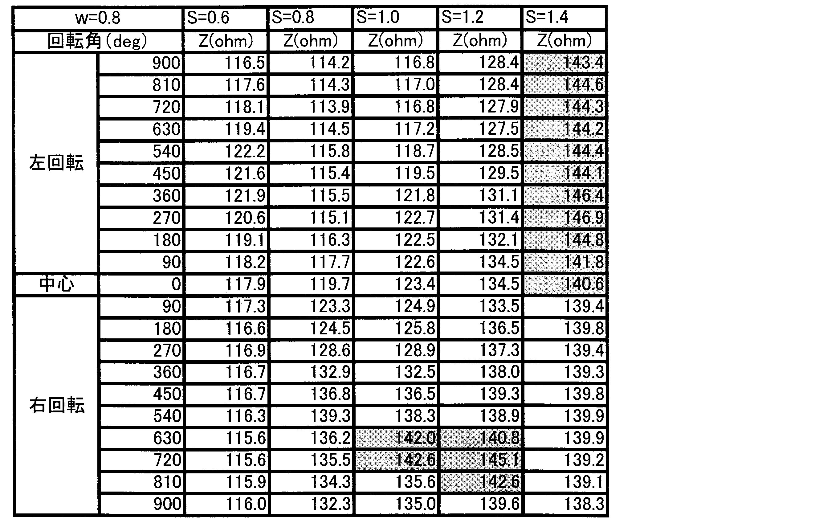
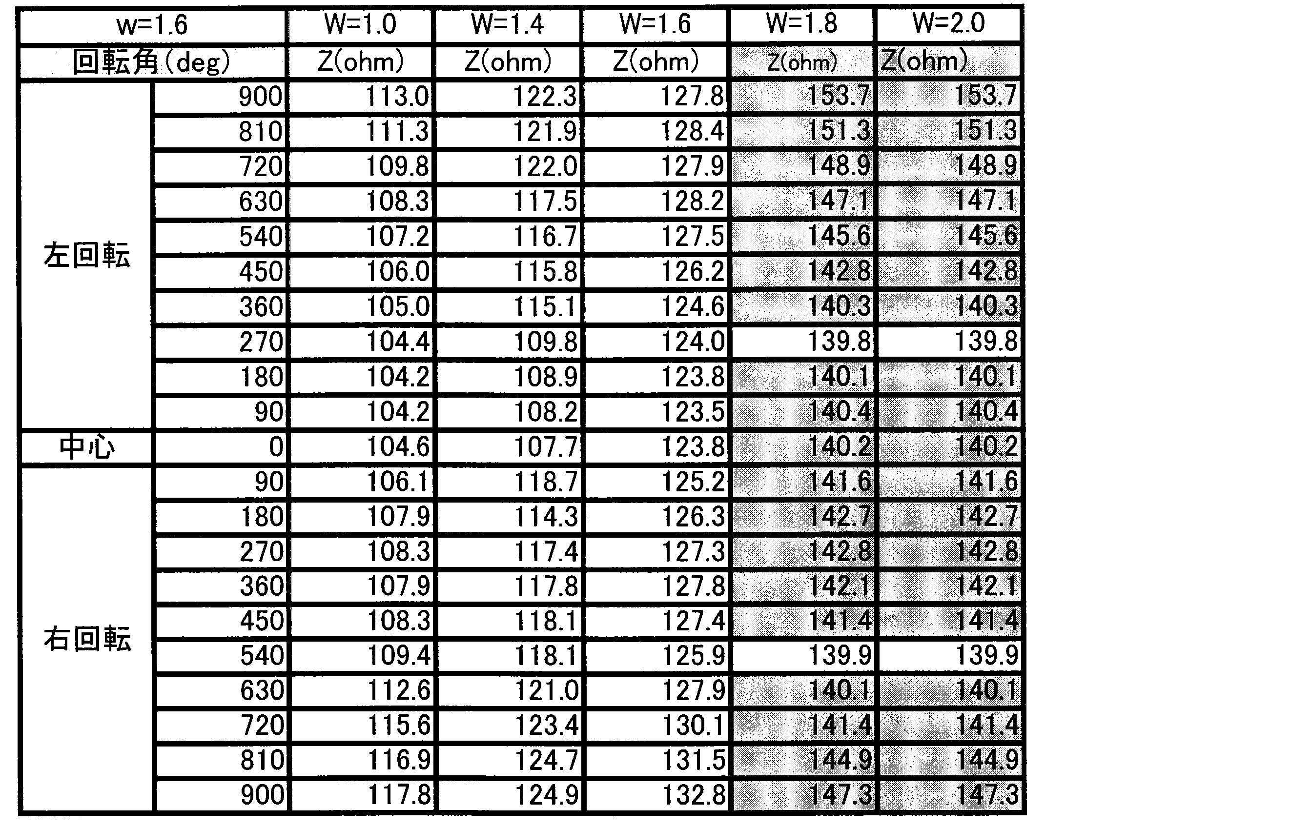
- the transmission line conductors of the superposed cable 100 constituted by two types of transmission lines FC101 in which the conductor width w of the transmission line conductor 130a constituting the transmission line conductor set 130 is 0.8 mm and 1.6 mm are used.
- the impedance (Z) when the SRC 10 was rotated was measured using the width-direction interval W that is the interval between the widths 130a as a parameter, and the influence of the width-direction interval W on the conductor width w was measured.
- a transmission line conductor 130a having a conductor thickness of 35 ⁇ m is used, the communication frequency is set to 1 MHz, and the range of “ ⁇ 25 ⁇ ” or “+ 20 ⁇ ” is set with an impedance of 120 ⁇ as a reference according to the CAN communication standard. Exceeded was rejected.
- the results when the width direction interval W is set to 0.6 mm, 0.8 mm, 1.0 mm, 1.2 mm, and 1.4 mm are shown in Table 1. Shown in Note that the rotation angle indicates a rotation angle rotated in the left-right direction around the intermediate position in the rotation direction, and impedance at the rotation angle is measured.
- the width-direction interval W of the pair of transmission line conductors 130a is not less than 0.35 mm, which is 10 times the thickness of the rectangular conductor 100b. Impedance can be reliably stabilized without lowering electromagnetic compatibility due to electromagnetic noise.
- the thickness of the rectangular conductor 100b is extremely small with respect to the conductor width w, the influence of the electrostatic coupling between the conductors acting on the impedance is relatively small, but the influence of the increase in the electrostatic coupling amount due to the proximity. Since it is received somewhat, 0.35 mm, which is 10 times or more the thickness of the rectangular conductor 100b, is set as the lower limit of the widthwise interval W, so that the electromagnetic compatibility due to electromagnetic noise is further reduced and the impedance is more reliably stabilized. can do.
- the width W between the transmission line conductor 130a and the circuit conductor 110 is also extremely thin, so that the influence of electrostatic coupling between the conductors acting on the impedance is small, but the influence can be completely eliminated. It is preferable that the width is at least the conductor width w of the circuit conductor 110.
- the width direction interval W in the signal conductor of the pair of transmission line conductors 130a is set to be equal to or less than the conductor width w of the flat rectangular conductor 100b and 10 times or more the thickness of the flat rectangular conductor 100b. Impedance can be more reliably stabilized by setting the distance in the width direction between the conductor 130a and the circuit conductor 110 to be equal to or greater than the conductor width w of the circuit conductor 110.
- the dummy FC102 is arranged on the front side of the transmission line FC101 to form the superposition cable 100 and wound and accommodated in the accommodation space S.
- the dummy FC102 is arranged on the back side of the transmission line FC101.
- the overlapping cable 100 may be configured by disposing dummy FCs 102 on both sides of the transmission line FC101.
- the superposition cable 100 is configured by the transmission path FC101 and the dummy FC102, the superposition cable 100 may be configured by overlapping a plurality of the transmission paths FC101 and the dummy FC102 in this order.
- the overlapping cable 100 includes a circuit conductor flat cable 103 having a circuit conductor 110 in addition to the transmission path FC101 and the dummy FC102, and the circuit conductor flat between the transmission path FC101 and the circuit conductor flat cable 103 and in the transmission path FC101.
- a dummy FC 102 is arranged on the side opposite to the side where the cable 103 is arranged.
- the transmission path FC101, the dummy FC102, and the circuit conductor flat cable 103 constituting the superposed cable 100 are in close contact with each other with grease 105 interposed therebetween. I am letting.
- the circuit conductor 110 is wound in the state where the superposed cable 100 is wound and accommodated in the accommodating space S. Because the dummy FC 102 is always interposed between the circuit conductor flat cable 103 having the transmission line FC101 and the transmission line FC101, the circuit conductor 110 in the circuit conductor flat cable 103 does not deteriorate electromagnetic compatibility due to electromagnetic noise without deteriorating the impedance. Can be stabilized.
- the rotary connector device of the present invention corresponds to SRC10
- the fixed side member corresponds to the stator 12
- the rotation side member corresponds to the rotator 13
- the flat cable corresponds to the superposed cable 100
- the signal conductor corresponds to the transmission line conductor 130a
- the strip-shaped resin corresponds to the laminate sheet 100a
- the signal flat cable corresponds to the transmission line FC101
- the dummy flat cable corresponds to the dummy FC102.
- the close contact means corresponds to the grease 105
- the conductor spacing corresponds to the widthwise spacing W
- the floating member corresponds to the retainer 16
- the folded portion corresponds to the U-turn portion 100c
- the SRC 10 to be mounted on the steering wheel portion in an automobile has been described, the above configuration may be used as a connector device in a mechanism having a rotating portion such as a robot arm.
Landscapes
- Engineering & Computer Science (AREA)
- Mechanical Engineering (AREA)
- Steering Controls (AREA)
Abstract
Description
さらには、上記ノイズ対策やインピーダンスの不安定化を解決するために信号伝送路を含むフラットケーブルにシールド層を適用する方法が提案されている(特許文献2参照)。
詳しくは、固定側部材と、該固定側部材に対して回転可能に取り付けられる回転側部材とで構成された環状の収容空間に収容されたフラットケーブルを、一対の信号導体を備え、帯状の樹脂で被覆した信号フラットケーブルと、該信号フラットケーブルの表裏面側の少なくとも一方に配置され、導体を含まない帯状の樹脂製のダミーフラットケーブルとを重ね合わせて構成し、重ね合わせた前記信号フラットケーブル及び前記ダミーフラットケーブルを密着させる密着手段を備えたことにより、フラットケーブルが有する弾発性が損なわれることなく、回転側部材を円滑に回転することができる。また、回転側部材の回転に伴うフラットケーブルの摺動や湾曲による座屈や摩滅によって、電磁ノイズによる電磁両立性が低下することなく、インピーダンスを安定させることができる。
この発明により、より安定したインピーダンスを実現することができる。
詳述すると、回転コネクタ装置では、導体の電気抵抗を下げたり軽量化を図ったりするため、フラットケーブルの長さは短いほうが好ましい。このため、フラットケーブルの一部に平面視U字状に湾曲した折返し部を有し、この折返し部をローラに引っ掛ける、いわゆるローラUターン式の回転コネクタ装置が一般に用いられている。
しかし、信号導体を有するフラットケーブルでローラを引っ張ったりすると、信頼性が低下するおそれがある。
なお、図1はステアリングロールコネクタ10(以下、「SRC10」という)の外観図を示し、図2はSRC10の分解斜視図を示し、図3はロテータ13を分離したSRC10の平面図を示している。また、図4はフラットケーブルの構成についての概念図を示し、図5はSRC10を用いて構成する伝送回路200の概念図を示している。また、図6は図3のA-A断面における重合せケーブル100についての概念図を示している。
ステータ12は、底板として環状に形成した固定側リング板12aと、この固定側リング板12aの外周縁から垂直に延びる円筒状の外周筒部12bとで構成している。固定側リング板12aの外周縁と外周筒部12bの下端とは嵌合により一体に構成している。
なお、ステータ12の外周筒部12bは、後述するロテータ13より大径に形成している。
さらに、ステータ12は、固定側コネクタ123を備えている。
なお、ロテータ13の回転軸方向は、上述したステアリングホイールの軸方向(図1,2中の上下方向)と同じ方向である。
また、前記内周筒部13bは、外周筒部12bと半径方向で対向するように配置されている。そして、ロテータ13は、回転側コネクタ133を備えている。
つまり、回路導体110は、伝送路導体組130よりも幅方向外側に配置している。
そして、伝送路導体組130を有する伝送路FC101によって回転側コネクタ133と接続される固定側コネクタ123は、図示省略するステアリングコラム内において車体側の導電回路等から引き出されたケーブル(図示省略)に接続され、回転側コネクタ133は、図示省略するステアリングホイール内において、例えば、ホーンスイッチ、エアバッグユニットなどの導電回路から引き出されたケーブル(図示省略)にそれぞれ接続される。
したがって、巻き回し状態において径方向に重ね合わさる伝送路FC101の伝送路導体組130同士間隔を、ダミーFC102によって適正距離で正確に保持することができる。
詳述すると、インピーダンス(Z)は下記数式1により算出される。
なお、下記数式1において、Lsはインダクタンス、Csは電気容量を示している。

また、伝送路FC101とダミーFC102とで重合せケーブル100を構成したが、伝送路FC101とダミーFC102とをこの順で複数重ね合わせて重合せケーブル100を構成してもよい。
以下同様に、
固定側部材は、ステータ12に対応し、
回転側部材は、ロテータ13に対応し、
フラットケーブルは、重合せケーブル100に対応し、
信号導体は、伝送路導体130aに対応し、
帯状の樹脂は、ラミネートシート100aに対応し、
信号フラットケーブルは、伝送路FC101に対応し、
ダミーフラットケーブルは、ダミーFC102に対応し、
密着手段は、グリス105に対応し、
導体間隔は、幅方向間隔Wに対応し、
遊動部材は、リテーナ16に対応し、
折返し部は、Uターン部100cに対応するも、
この発明は、上述の実施形態の構成のみに限定されるものではなく、請求項に示される技術思想に基づいて応用することができ、多くの実施の形態を得ることができる。
12…ステータ
13…ロテータ
16…リテーナ
16a…ローラ
100…重合せケーブル
100a…ラミネートシート
100c…Uターン部
101…伝送路FC
102…ダミーFC
103…回路導体フラットケーブル
105…グリス
回路導体110…回路導体
130a…伝送路導体
S…収容空間
W…幅方向間隔
w…導体幅
Claims (4)
- 固定側部材と、該固定側部材に対して回転可能に取り付けられる回転側部材とを有し、これらで構成された環状の収容空間に、フラットケーブルを収容した回転コネクタ装置であって、
前記フラットケーブルを、
一対の信号導体を備え、帯状の樹脂で被覆した信号フラットケーブルと、該信号フラットケーブルの表裏面側の少なくとも一方に配置され、導体を含まない帯状で樹脂製のダミーフラットケーブルとを重ね合わせて構成し、
重ね合わせた前記信号フラットケーブル及び前記ダミーフラットケーブルを密着させる密着手段を備え、
前記一対の信号導体における導体間隔を、前記信号導体の導体幅に対して同等以下に設定した
回転コネクタ装置。 - 前記一対の信号導体における導体間隔を、前記信号導体の厚みの10倍以上に設定した
請求項1に記載の回転コネクタ装置。 - 前記回転側部材を、回転軸に対して両回転方向に回転自在に構成するとともに、
前記収容空間に、上面にローラを備えた環状の遊動部材を配置し、
前記フラットケーブルの長手方向の一部に、前記ローラによって湾曲して折り返される折返し部を形成し、
前記フラットケーブルを前記遊動部材上に保持する
請求項1または2に記載の回転コネクタ装置。 - 前記フラットケーブルを、
前記信号フラットケーブル及び前記ダミーフラットケーブルに加えて、回路を構成する回路を構成する回路導体を有する回路導体フラットケーブルを備え、
前記信号フラットケーブルと前記回路導体フラットケーブルとの間、及び前記信号フラットケーブルにおける前記回路導体フラットケーブルを配置した側と反対側に、前記ダミーフラットケーブルを配置した
請求項1乃至3のうちいずれかに記載の回転コネクタ装置。
Priority Applications (5)
| Application Number | Priority Date | Filing Date | Title |
|---|---|---|---|
| CN201380006672.7A CN104081595B (zh) | 2012-07-26 | 2013-07-26 | 旋转连接器装置 |
| JP2014527035A JP6005156B2 (ja) | 2012-07-26 | 2013-07-26 | 回転コネクタ装置 |
| KR1020157004443A KR101774424B1 (ko) | 2012-07-26 | 2013-07-26 | 회전 커넥터 장치 |
| EP13822340.9A EP2879248B1 (en) | 2012-07-26 | 2013-07-26 | Rotary connector device |
| US14/513,726 US9300100B2 (en) | 2012-07-26 | 2014-10-14 | Rotatable connector device having a signal flat cable and a dummy flat cable stacked over and slidable with respect to each other |
Applications Claiming Priority (2)
| Application Number | Priority Date | Filing Date | Title |
|---|---|---|---|
| JP2012-165316 | 2012-07-26 | ||
| JP2012165316 | 2012-07-26 |
Related Child Applications (1)
| Application Number | Title | Priority Date | Filing Date |
|---|---|---|---|
| US14/513,726 Continuation US9300100B2 (en) | 2012-07-26 | 2014-10-14 | Rotatable connector device having a signal flat cable and a dummy flat cable stacked over and slidable with respect to each other |
Publications (1)
| Publication Number | Publication Date |
|---|---|
| WO2014017649A1 true WO2014017649A1 (ja) | 2014-01-30 |
Family
ID=49997453
Family Applications (1)
| Application Number | Title | Priority Date | Filing Date |
|---|---|---|---|
| PCT/JP2013/070371 Ceased WO2014017649A1 (ja) | 2012-07-26 | 2013-07-26 | 回転コネクタ装置 |
Country Status (6)
| Country | Link |
|---|---|
| US (1) | US9300100B2 (ja) |
| EP (1) | EP2879248B1 (ja) |
| JP (1) | JP6005156B2 (ja) |
| KR (1) | KR101774424B1 (ja) |
| CN (1) | CN104081595B (ja) |
| WO (1) | WO2014017649A1 (ja) |
Cited By (1)
| Publication number | Priority date | Publication date | Assignee | Title |
|---|---|---|---|---|
| WO2022130895A1 (ja) | 2020-12-15 | 2022-06-23 | 古河電気工業株式会社 | 回転コネクタ装置 |
Families Citing this family (5)
| Publication number | Priority date | Publication date | Assignee | Title |
|---|---|---|---|---|
| EP2685571B1 (en) * | 2011-03-09 | 2017-05-03 | Furukawa Electric Co., Ltd. | Rotatable connector device |
| US9647383B2 (en) * | 2013-12-31 | 2017-05-09 | 3M Innovative Properties Company | Right angle exit connector assembly |
| WO2018055884A1 (ja) * | 2016-09-20 | 2018-03-29 | 古河電気工業株式会社 | フラットケーブル、フラットケーブルの製造方法、及びフラットケーブルを備える回転コネクタ装置 |
| WO2019181841A1 (ja) * | 2018-03-19 | 2019-09-26 | 古河電気工業株式会社 | 回転コネクタ装置及び回転コネクタ装置の組付構造 |
| WO2019181049A1 (ja) * | 2018-03-22 | 2019-09-26 | アルプスアルパイン株式会社 | 回転コネクタ |
Citations (5)
| Publication number | Priority date | Publication date | Assignee | Title |
|---|---|---|---|---|
| JPH05234651A (ja) * | 1992-02-20 | 1993-09-10 | Furukawa Electric Co Ltd:The | 回転体と固定体間の伝送装置 |
| JP2008035677A (ja) * | 2006-07-31 | 2008-02-14 | Furukawa Electric Co Ltd:The | 回転コネクタ装置 |
| JP2009104907A (ja) | 2007-10-24 | 2009-05-14 | Tokai Rika Co Ltd | ツイストペアフラットケーブル |
| JP2009152089A (ja) * | 2007-12-21 | 2009-07-09 | Furukawa Electric Co Ltd:The | 回転コネクタ装置 |
| WO2011136008A1 (ja) | 2010-04-28 | 2011-11-03 | 古河電気工業株式会社 | 回転コネクタ装置 |
Family Cites Families (11)
| Publication number | Priority date | Publication date | Assignee | Title |
|---|---|---|---|---|
| US5105055A (en) * | 1990-10-17 | 1992-04-14 | Digital Equipment Corporation | Tunnelled multiconductor system and method |
| JP3373966B2 (ja) * | 1995-02-10 | 2003-02-04 | アルプス電気株式会社 | 回転コネクタ |
| JPH08241777A (ja) * | 1995-03-03 | 1996-09-17 | Furukawa Electric Co Ltd:The | 回転体と固定体間の伝送装置 |
| DE19701510A1 (de) * | 1997-01-17 | 1998-07-23 | Stemmann Technik Gmbh | Signalleiter |
| EP0938099A1 (en) * | 1997-05-16 | 1999-08-25 | The Furukawa Electric Co., Ltd. | Flat cable and method of manufacturing the same |
| US6770820B2 (en) * | 2000-07-12 | 2004-08-03 | Kabushiki Kaisha Bridgestone | Shielded flat cable |
| US6969807B1 (en) * | 2004-07-20 | 2005-11-29 | Advanced Flexible Circuits Co., Ltd. | Planar type flexible cable with shielding structure |
| US7755445B2 (en) * | 2004-08-03 | 2010-07-13 | Banpil Photonics, Inc. | Multi-layered high-speed printed circuit boards comprised of stacked dielectric systems |
| US7663064B2 (en) * | 2004-09-25 | 2010-02-16 | Banpil Photonics, Inc. | High-speed flex printed circuit and method of manufacturing |
| WO2011142341A1 (ja) | 2010-05-10 | 2011-11-17 | 古河電気工業株式会社 | 回転コネクタ装置 |
| KR101322593B1 (ko) * | 2011-03-14 | 2013-10-28 | 알프스 덴키 가부시키가이샤 | 회전 커넥터 |
-
2013
- 2013-07-26 KR KR1020157004443A patent/KR101774424B1/ko active Active
- 2013-07-26 CN CN201380006672.7A patent/CN104081595B/zh active Active
- 2013-07-26 EP EP13822340.9A patent/EP2879248B1/en active Active
- 2013-07-26 WO PCT/JP2013/070371 patent/WO2014017649A1/ja not_active Ceased
- 2013-07-26 JP JP2014527035A patent/JP6005156B2/ja active Active
-
2014
- 2014-10-14 US US14/513,726 patent/US9300100B2/en active Active
Patent Citations (5)
| Publication number | Priority date | Publication date | Assignee | Title |
|---|---|---|---|---|
| JPH05234651A (ja) * | 1992-02-20 | 1993-09-10 | Furukawa Electric Co Ltd:The | 回転体と固定体間の伝送装置 |
| JP2008035677A (ja) * | 2006-07-31 | 2008-02-14 | Furukawa Electric Co Ltd:The | 回転コネクタ装置 |
| JP2009104907A (ja) | 2007-10-24 | 2009-05-14 | Tokai Rika Co Ltd | ツイストペアフラットケーブル |
| JP2009152089A (ja) * | 2007-12-21 | 2009-07-09 | Furukawa Electric Co Ltd:The | 回転コネクタ装置 |
| WO2011136008A1 (ja) | 2010-04-28 | 2011-11-03 | 古河電気工業株式会社 | 回転コネクタ装置 |
Non-Patent Citations (1)
| Title |
|---|
| See also references of EP2879248A4 |
Cited By (3)
| Publication number | Priority date | Publication date | Assignee | Title |
|---|---|---|---|---|
| WO2022130895A1 (ja) | 2020-12-15 | 2022-06-23 | 古河電気工業株式会社 | 回転コネクタ装置 |
| KR20230118826A (ko) | 2020-12-15 | 2023-08-14 | 후루카와 덴키 고교 가부시키가이샤 | 회전 커넥터 장치 |
| US12506310B2 (en) | 2020-12-15 | 2025-12-23 | Furukawa Electric Co., Ltd. | Rotating connector device |
Also Published As
| Publication number | Publication date |
|---|---|
| KR101774424B1 (ko) | 2017-09-04 |
| CN104081595A (zh) | 2014-10-01 |
| EP2879248A4 (en) | 2016-03-23 |
| US20150031219A1 (en) | 2015-01-29 |
| EP2879248B1 (en) | 2018-03-21 |
| JPWO2014017649A1 (ja) | 2016-07-11 |
| JP6005156B2 (ja) | 2016-10-12 |
| EP2879248A1 (en) | 2015-06-03 |
| US9300100B2 (en) | 2016-03-29 |
| KR20150038194A (ko) | 2015-04-08 |
| CN104081595B (zh) | 2016-08-24 |
Similar Documents
| Publication | Publication Date | Title |
|---|---|---|
| JP6005156B2 (ja) | 回転コネクタ装置 | |
| JP5823380B2 (ja) | 回転コネクタ装置 | |
| JP7196909B2 (ja) | シールドフラットケーブル | |
| EP4254685B1 (en) | Rotating connector device | |
| JP2001135156A (ja) | フラットケーブル | |
| JP5802156B2 (ja) | 回転コネクタ | |
| CN106031309A (zh) | 柔性印刷电路板和柔性印刷电路板的制造方法 | |
| EP3509168B1 (en) | Rotary connector device | |
| JP2012221739A (ja) | ケーブル | |
| WO2023248537A1 (ja) | 回転コネクタ | |
| JP5867370B2 (ja) | 差動信号伝送用ケーブル及びその製造方法 | |
| WO2025023173A1 (ja) | フレキシブルフラットケーブルおよび給電装置 | |
| JP2025070025A (ja) | 配線構造体および給電装置 | |
| JP5872933B2 (ja) | 回転コネクタ | |
| JP2024118930A (ja) | ケーブルコネクタ組立体、ケーブルコネクタ組立体を用いた回転コネクタ装置及びケーブルコネクタ組立体の製造方法 | |
| JPH0794221A (ja) | フラットケーブルの接続構造 | |
| JP2005039870A (ja) | スパイラルケーブル装置 | |
| WO2017104548A1 (ja) | 回転コネクタ |
Legal Events
| Date | Code | Title | Description |
|---|---|---|---|
| ENP | Entry into the national phase |
Ref document number: 2014527035 Country of ref document: JP Kind code of ref document: A |
|
| 121 | Ep: the epo has been informed by wipo that ep was designated in this application |
Ref document number: 13822340 Country of ref document: EP Kind code of ref document: A1 |
|
| WWE | Wipo information: entry into national phase |
Ref document number: 2013822340 Country of ref document: EP |
|
| NENP | Non-entry into the national phase |
Ref country code: DE |
|
| ENP | Entry into the national phase |
Ref document number: 20157004443 Country of ref document: KR Kind code of ref document: A |