WO2014017450A1 - 媒体支持装置および媒体加工装置 - Google Patents
媒体支持装置および媒体加工装置 Download PDFInfo
- Publication number
- WO2014017450A1 WO2014017450A1 PCT/JP2013/069833 JP2013069833W WO2014017450A1 WO 2014017450 A1 WO2014017450 A1 WO 2014017450A1 JP 2013069833 W JP2013069833 W JP 2013069833W WO 2014017450 A1 WO2014017450 A1 WO 2014017450A1
- Authority
- WO
- WIPO (PCT)
- Prior art keywords
- medium
- platen
- cutting
- hole
- cylindrical member
- Prior art date
- Legal status (The legal status is an assumption and is not a legal conclusion. Google has not performed a legal analysis and makes no representation as to the accuracy of the status listed.)
- Ceased
Links
Images


Classifications
-
- B—PERFORMING OPERATIONS; TRANSPORTING
- B41—PRINTING; LINING MACHINES; TYPEWRITERS; STAMPS
- B41J—TYPEWRITERS; SELECTIVE PRINTING MECHANISMS, i.e. MECHANISMS PRINTING OTHERWISE THAN FROM A FORME; CORRECTION OF TYPOGRAPHICAL ERRORS
- B41J11/00—Devices or arrangements of selective printing mechanisms, e.g. ink-jet printers or thermal printers, for supporting or handling copy material in sheet or web form
- B41J11/0085—Using suction for maintaining printing material flat
-
- B—PERFORMING OPERATIONS; TRANSPORTING
- B26—HAND CUTTING TOOLS; CUTTING; SEVERING
- B26D—CUTTING; DETAILS COMMON TO MACHINES FOR PERFORATING, PUNCHING, CUTTING-OUT, STAMPING-OUT OR SEVERING
- B26D7/00—Details of apparatus for cutting, cutting-out, stamping-out, punching, perforating, or severing by means other than cutting
- B26D7/01—Means for holding or positioning work
- B26D7/018—Holding the work by suction
-
- B—PERFORMING OPERATIONS; TRANSPORTING
- B26—HAND CUTTING TOOLS; CUTTING; SEVERING
- B26D—CUTTING; DETAILS COMMON TO MACHINES FOR PERFORATING, PUNCHING, CUTTING-OUT, STAMPING-OUT OR SEVERING
- B26D7/00—Details of apparatus for cutting, cutting-out, stamping-out, punching, perforating, or severing by means other than cutting
- B26D7/20—Cutting beds
-
- B—PERFORMING OPERATIONS; TRANSPORTING
- B26—HAND CUTTING TOOLS; CUTTING; SEVERING
- B26F—PERFORATING; PUNCHING; CUTTING-OUT; STAMPING-OUT; SEVERING BY MEANS OTHER THAN CUTTING
- B26F1/00—Perforating; Punching; Cutting-out; Stamping-out; Apparatus therefor
- B26F1/38—Cutting-out; Stamping-out
- B26F1/3806—Cutting-out; Stamping-out wherein relative movements of tool head and work during cutting have a component tangential to the work surface
- B26F1/3813—Cutting-out; Stamping-out wherein relative movements of tool head and work during cutting have a component tangential to the work surface wherein the tool head is moved in a plane parallel to the work in a coordinate system fixed with respect to the work
-
- B—PERFORMING OPERATIONS; TRANSPORTING
- B41—PRINTING; LINING MACHINES; TYPEWRITERS; STAMPS
- B41J—TYPEWRITERS; SELECTIVE PRINTING MECHANISMS, i.e. MECHANISMS PRINTING OTHERWISE THAN FROM A FORME; CORRECTION OF TYPOGRAPHICAL ERRORS
- B41J11/00—Devices or arrangements of selective printing mechanisms, e.g. ink-jet printers or thermal printers, for supporting or handling copy material in sheet or web form
- B41J11/02—Platens
- B41J11/06—Flat page-size platens or smaller flat platens having a greater size than line-size platens
-
- B—PERFORMING OPERATIONS; TRANSPORTING
- B41—PRINTING; LINING MACHINES; TYPEWRITERS; STAMPS
- B41J—TYPEWRITERS; SELECTIVE PRINTING MECHANISMS, i.e. MECHANISMS PRINTING OTHERWISE THAN FROM A FORME; CORRECTION OF TYPOGRAPHICAL ERRORS
- B41J11/00—Devices or arrangements of selective printing mechanisms, e.g. ink-jet printers or thermal printers, for supporting or handling copy material in sheet or web form
- B41J11/66—Applications of cutting devices
- B41J11/70—Applications of cutting devices cutting perpendicular to the direction of paper feed
-
- B—PERFORMING OPERATIONS; TRANSPORTING
- B41—PRINTING; LINING MACHINES; TYPEWRITERS; STAMPS
- B41J—TYPEWRITERS; SELECTIVE PRINTING MECHANISMS, i.e. MECHANISMS PRINTING OTHERWISE THAN FROM A FORME; CORRECTION OF TYPOGRAPHICAL ERRORS
- B41J3/00—Typewriters or selective printing or marking mechanisms characterised by the purpose for which they are constructed
- B41J3/28—Typewriters or selective printing or marking mechanisms characterised by the purpose for which they are constructed for printing downwardly on flat surfaces, e.g. of books, drawings, boxes, envelopes, e.g. flat-bed ink-jet printers
-
- B—PERFORMING OPERATIONS; TRANSPORTING
- B65—CONVEYING; PACKING; STORING; HANDLING THIN OR FILAMENTARY MATERIAL
- B65H—HANDLING THIN OR FILAMENTARY MATERIAL, e.g. SHEETS, WEBS, CABLES
- B65H1/00—Supports or magazines for piles from which articles are to be separated
- B65H1/04—Supports or magazines for piles from which articles are to be separated adapted to support articles substantially horizontally, e.g. for separation from top of pile
-
- F—MECHANICAL ENGINEERING; LIGHTING; HEATING; WEAPONS; BLASTING
- F16—ENGINEERING ELEMENTS AND UNITS; GENERAL MEASURES FOR PRODUCING AND MAINTAINING EFFECTIVE FUNCTIONING OF MACHINES OR INSTALLATIONS; THERMAL INSULATION IN GENERAL
- F16M—FRAMES, CASINGS OR BEDS OF ENGINES, MACHINES OR APPARATUS, NOT SPECIFIC TO ENGINES, MACHINES OR APPARATUS PROVIDED FOR ELSEWHERE; STANDS; SUPPORTS
- F16M11/00—Stands or trestles as supports for apparatus or articles placed thereon ; Stands for scientific apparatus such as gravitational force meters
-
- F—MECHANICAL ENGINEERING; LIGHTING; HEATING; WEAPONS; BLASTING
- F16—ENGINEERING ELEMENTS AND UNITS; GENERAL MEASURES FOR PRODUCING AND MAINTAINING EFFECTIVE FUNCTIONING OF MACHINES OR INSTALLATIONS; THERMAL INSULATION IN GENERAL
- F16M—FRAMES, CASINGS OR BEDS OF ENGINES, MACHINES OR APPARATUS, NOT SPECIFIC TO ENGINES, MACHINES OR APPARATUS PROVIDED FOR ELSEWHERE; STANDS; SUPPORTS
- F16M13/00—Other supports for positioning apparatus or articles; Means for steadying hand-held apparatus or articles
-
- F—MECHANICAL ENGINEERING; LIGHTING; HEATING; WEAPONS; BLASTING
- F16—ENGINEERING ELEMENTS AND UNITS; GENERAL MEASURES FOR PRODUCING AND MAINTAINING EFFECTIVE FUNCTIONING OF MACHINES OR INSTALLATIONS; THERMAL INSULATION IN GENERAL
- F16M—FRAMES, CASINGS OR BEDS OF ENGINES, MACHINES OR APPARATUS, NOT SPECIFIC TO ENGINES, MACHINES OR APPARATUS PROVIDED FOR ELSEWHERE; STANDS; SUPPORTS
- F16M2200/00—Details of stands or supports
Definitions
- the present invention relates to a medium support apparatus and a medium processing apparatus, and more specifically, includes a medium support apparatus for supporting the medium when processing such as printing and cutting on the medium, and the medium support apparatus.
- the present invention relates to a medium processing apparatus.
- Examples of the medium processing apparatus include an inkjet printing apparatus that performs printing on a medium, or a cutting apparatus that performs cutting on a medium.
- an operation for reciprocally moving a printing unit equipped with an ink jet head for ejecting ink left and right and an operation for feeding the medium back and forth is known.
- Inkjet printing apparatuses capable of printing a desired image on a medium by combining the above and the like are known.
- a cutting device capable of performing a desired cutting process is also known.
- a desired image is printed by the ink jet printing apparatus using a medium in which a mount and a sticker paper are bonded, and the medium is cut along the contour of the desired image by the cutting apparatus. It is possible to create seals with various patterns and shapes.
- a printing and cutting apparatus has been developed in which a cutting unit is additionally mounted on the inkjet printing apparatus so that printing and cutting can be performed with a single apparatus (see Patent Document 1).
- a platen (hereinafter simply referred to as “platen”) as a medium support device for supporting the medium when processing the medium is formed with high accuracy so as not to be distorted. Is very important.
- a conventional platen in the case of a flat-bed type ink jet printing apparatus, includes a lower panel and an upper panel joined to the lower panel via an intermediate structure. Further, there is a configuration in which the upper panel is provided with a large number of suction holes and air suction means for sucking air in a closed space formed between the lower panel and the upper panel. According to this configuration, when air in the closed space is sucked by the air sucking means, air is sucked from the suction holes of the upper panel, so that an action of adsorbing the medium to the upper panel can be obtained.
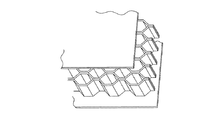
- a honeycomb structure has been conventionally used (see FIG. 11).
- a honeycomb formed by laminating thin plate-like members made of a material such as an aluminum alloy or a carbon graphite sheet bonded with a polymer film while intermittently adhering them, and extending the laminate in the laminating direction.
- a structure is known (see Patent Document 2).
- JP 2003-266377 A Japanese Patent No. 4244627
- the platen intermediate structure exemplified above includes a step of cutting (or forming) a thin plate made of an aluminum alloy or the like into a predetermined shape, and a step of laminating and stretching the thin plate while intermittently bonding the thin plate. Since the honeycomb structure is formed, there has been a problem that it is very costly to obtain a highly accurate honeycomb structure by accurately carrying out these steps.
- the adsorption holes may interfere with the intermediate structure (honeycomb structure), and the adsorption holes are blocked by the honeycomb structure. Therefore, there is a problem that the medium adsorption force is biased.
- the present invention has been made in view of the above problems, and is a medium support device that is lightweight, low-cost, and highly accurate even when the area of the medium support surface is large, and It is an object of the present invention to provide a medium processing apparatus provided with the medium support apparatus.
- the disclosed medium support device includes a plurality of cylindrical members arranged in parallel at predetermined intervals so that the openings are directed in the same direction, and a first plate shape joined to the cylindrical member so as to close the openings. And a member.
- a plurality of tubular members can be used as the intermediate structure bonded to the first plate-shaped member. Therefore, there is no need for a step of cutting (or forming) a thin plate made of an aluminum alloy or the like necessary for forming the honeycomb structure, or a step of laminating and extending the thin plate while intermittently bonding the thin plate.
- the intermediate structure can be formed at a very low cost, and the cost of the platen can be reduced. Further, it is possible to easily achieve high accuracy of the platen simply by forming each cylindrical member (particularly the axial dimension) within a predetermined accuracy range. Further, the platen can be reduced in weight by forming the cylindrical member using, for example, a resin material.
- the said 1st plate-shaped member has the 1st hole part penetrated in the front and back.
- the plurality of cylindrical members are preferably disposed in a closed space formed between the first plate-like member and the second plate-like member.
- the closed space is formed by sealing the outer periphery of the platen with a resin material such as rubber. According to this, by using the air suction means to make the inside of the closed space have a negative pressure, an action of sucking air in the direction toward the inside of the closed space at the first hole portion is obtained, and the medium is moved to the first plate. It becomes possible to support it by adsorbing it on the member.
- the first plate-like member has a first hole penetrating the front and back at a position where the opening of the tubular member is blocked, and the tubular member It is preferable to have the 2nd hole part penetrated in. According to this, when the inside of a closed space is made into a negative pressure by providing a through-hole (2nd hole part) in the side surface of a cylindrical member, the inside of a cylindrical member can also be made into a negative pressure. Therefore, in the first plate-like member, it is possible to provide the suction hole (first hole) at a position corresponding to the opening of the cylindrical member. Can be improved.
- a spacer for arranging the plurality of cylindrical members side by side at equal intervals is provided. According to this, it becomes possible to arrange a plurality of cylindrical members in parallel with a minimum number to the extent that the deformation amount is allowed in the first plate-like member. Therefore, the cost of the intermediate structure and the platen can be further reduced. Further, by providing the spacer, it becomes easy to arrange the cylindrical members in parallel, so that the platen can be manufactured easily and at a low cost. Further, when the cylindrical member is formed using, for example, a resin material, the outer peripheral portion is so-called thicker than that formed using a metal material (that is, the difference between the inner diameter and the outer diameter is large).
- the second hole of the cylindrical member is provided at a position that does not interfere with the side surface of the spacer. If the second hole of the cylindrical member interferes with the side surface of the spacer, the inside of the cylindrical member cannot be made negative even if the inside of the closed space is negative. The subject that it becomes impossible to generate
- the disclosed medium processing apparatus includes the medium support device and air suction means for sucking air in the closed space. According to this, it is possible to process the medium with high accuracy by applying the above-described medium support device that is lightweight, low-cost, and can be formed with high accuracy, and is lightweight and low-cost. It becomes possible to realize a medium processing apparatus with a low cost. In particular, it is suitable for application to a large flat bed type apparatus.
- the disclosed medium support apparatus even if the area of the medium support surface is large, it can be formed with high accuracy with low weight and low cost. Further, by applying the medium support apparatus to a medium processing apparatus, it becomes possible to process the medium with high accuracy.
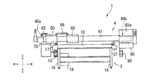
- FIG. 1 is a schematic perspective view of a printing / cutting apparatus 1 including a medium support apparatus (a platen 10) according to the present embodiment.
- FIG. 2 is a schematic rear view of the print cutting apparatus 1.
- the front / rear, left / right, and up / down directions of the printing / cutting apparatus 1 are indicated by the arrow directions in FIGS. 1 and 2.
- the front-rear direction of the paper surface in FIG. 2 is the front-rear direction of the print cutting apparatus 1.
- the printing / cutting apparatus 1 includes an inkjet head 60 and a cutting head 50, and performs only printing and cutting only on a sheet-like medium supported by the platen 10.
- the apparatus performs an operation selected according to the purpose from among an operation to be performed and an operation to collectively perform printing and cut processing corresponding to the printed image.
- the print cutting apparatus 1 is configured by assembling a second subassembly 4 above the first subassembly 3 as an overall configuration.
- the first subassembly 3 is configured by providing front and rear moving mechanisms 17 and 17 extending in the front-rear direction on the left and right sides of the platen 10 that supports the medium that is the workpiece.
- a power source and control equipment 18 are disposed below the platen 10.
- the second subassembly 4 has an inkjet head 60 and a cutting head 50 attached to the left and right along a long guide bar member 40 extending left and right.
- a left / right moving mechanism 30 (see FIGS. 3A and 3B) is provided.
- an ink supply device 70 and a maintenance unit 80 are attached to the left end portion and the right end portion of the guide bar member 40, respectively.
- the platen 10 has a plurality of legs 16, 16,... 1 plate-like member (hereinafter referred to as “upper panel”) 11 and a second plate-like member (hereinafter referred to as “lower panel”) 21 that supports the upper panel 11 via the intermediate structure 25.
- the upper panel 11 is disposed at a predetermined height position on the floor surface.
- the upper panel 11 is provided with a plurality of holes (hereinafter referred to as “first holes”) 12 penetrating through the front and back (penetrating in the thickness direction).
- the medium can be adsorbed and supported on the upper panel 11 by sucking air from the front surface to the back surface of the first hole portion 12 using the air suction means 23 (details). Will be described later).
- the guide bar member 40 is disposed above the platen 10
- the left and right end portions 40 a and 40 b of the guide bar member 40 are formed on the platen 10 because the left and right lengths are longer than the platen 10.
- the structure protrudes from side to side.
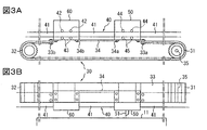
- FIGS. 3A and 3B FIGS. 3A and 3B (FIG. 3A is a schematic plan view, and FIG. 3B is a schematic rear view), the left-right moving mechanism 30 provided in the second subassembly 4
- the sprocket 32 includes a toothed belt 33 wound around the drive sprocket 31 and the driven sprocket 32, and a connecting member 34 that connects the cutting head 50 and the inkjet head 60.
- the toothed belt 33 has one end 33 a attached to the inkjet head 60 and the other end 33 b attached to the cutting head 50.
- the connecting member 34 has one end 34 a attached to the inkjet head 60 and the other end 34 b attached to the cutting head 50. Note that the cutting head 50 and the inkjet head 60 may be integrally attached to the toothed belt 33 without using the connecting member 34.
- the drive sprocket 31 and the driven sprocket 32 are supported rotatably at the left end portion and the right end portion of the platen 10, respectively.
- the drive sprocket 31 is connected to a drive motor (not shown) via a shaft 35 and is configured to be rotatable by the rotational driving force of the drive motor.
- two pairs of front and rear guide rollers 42 and 43 each having a vertical axis as a rotation axis are attached to the inside of the cutting head 50 with a space left and right.
- the pair of front and rear guide rollers 42 and 43 are attached to the guide bar member 40 so as to be able to roll by sandwiching a guide rail 41 disposed so as to extend horizontally from side to side. With this configuration, the cutting head 50 can move left and right along the guide rail 41.
- two pairs of front and rear guide rollers 44, 45 each having a vertical axis as a rotation axis are attached to the left and right at intervals.
- the pair of front and rear guide rollers 44 and 45 are attached so as to sandwich the guide rail 41 forward and backward. With this configuration, the ink jet head 60 can move to the left and right along the guide rail 41.
- the drive sprocket 31 is rotationally driven via the shaft 35, and the toothed belt 33 moves left and right, and is attached to the toothed belt 33.
- Both the cutting head 50 and the ink jet head 60 thus obtained can move left and right while being guided by the guide rail 41 while maintaining their distance by the connecting member 34 connecting them.
- the cutting head 50 projects downwardly into the lower surface of the cutting head 50 to make a cut in the surface of the medium that is the object to be processed (the seal portion of the surface with the adhesive without cutting into the medium mount)
- a cutter 51 is attached so as to be movable up and down (see FIG. 3B).
- the cutting operation by the cutter 51 may be an operation of cutting by cutting the medium including the base paper in addition to the cutting operation only on the surface of the medium as described above.
- the inkjet head 60 includes a plurality of inkjet nozzles (hereinafter, referred to as “nozzles”) 61, 61,... Arranged on the left and right sides (see FIG. 4A). 61, 61,..., Ink passages 62 are formed by opening the ejection openings 62a downward (see FIG. 4B).
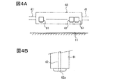
- FIG. 4A is a schematic diagram illustrating a configuration example of the plurality of nozzles 61
- FIG. 4B is a schematic diagram illustrating a configuration example around the tip of the nozzle 61.
- an ink supply device 70 for supplying ink to the ink passage 62 is provided at the right end portion 40 a of the guide bar member 40, and movement control of the cutting head 50 and the inkjet head 60 and ink ejection in the inkjet head 60 are provided.
- a control device (not shown) for performing control is provided (see FIG. 2).
- a housing 80a that covers the left end 40b is provided at the left end 40b of the guide bar member 40, and a maintenance unit 80 is provided therein.
- the maintenance unit 80 sucks the ink remaining in the ink passage 62 or removes ink fountains or dust adhering to the periphery of the ejection opening 62a, so that the ink is ejected normally from the ejection opening 62a. It is a mechanism for recovering to the state to be done. Further, a waste ink tank 90 is provided below the maintenance unit 80 so that ink processed in the maintenance unit 80 can be stored.
- a first flexible cable guide 15 (for example, a cable bear (registered trademark)) that connects the lower right portion of the platen 10 and the ink supply device 70 is provided.
- the first flexible cable guide 15 is supplied with power and control signals for driving and controlling the devices on the second subassembly 4 side from the power supply and control device 18 disposed in the platen 10.
- power and a control signal can be supplied from the first subassembly 3 side to the second subassembly 4 side while allowing the guide bar member 40 to move back and forth with respect to the platen 10.
- a second flexible cable guide 65 that connects the right end 40a of the guide bar member 40 and the cutting head 50 is provided. Inside the second flexible cable guide 65, power and control signals are supplied from the control device 18 to control the movement of the cutter 51 of the cutting head 50 up and down and to control the movement of the nozzle 61 of the inkjet head 60 up and down.
- An electric wire for supplying ink and a tube for supplying ink from the ink supply device 70 to the inkjet head 60 via the cutting head 50 are disposed. According to this, electric power, a control signal, and ink can be supplied from the ink supply device 70 side to the cutting head 50 side.
- a third flexible cable guide 66 is provided to connect the cutting head 50 and the inkjet head 60.
- a tube for supplying ink to 60 is disposed. According to this, electric power, a control signal, and ink can be supplied from the cutting head 50 side to the inkjet head 60 side.
- the print cutting apparatus 1 performs an operation of performing only printing on a medium, an operation of performing only cutting processing, and printing and cutting processing corresponding to the printed image. It is possible to execute an operation selected according to the purpose from among the operations performed collectively. For example, the operation of collectively performing printing and cutting will be described.
- the guide bar member 40 is moved back and forth with respect to the platen 10, and the ejection opening 62a is opposed to the surface of the medium held by the platen 10. While moving the inkjet head 60 back and forth and right and left. During this movement, ink is ejected from the ejection openings 62a, and desired characters and designs are printed on the upper surface of the medium.
- the guide bar member 40 is moved back and forth with respect to the platen 10, and the cutting head 50 is moved back and forth, right and left while the cutting edge of the cutter 51 provided at the lower part of the cutting head 50 is directed toward the surface of the medium held by the platen 10.
- the surface of the medium at a desired position of the medium is cut. As described above, it is very efficient in that printing and cutting of a desired image can be continuously performed without removing the medium from the platen 10 each time.
- the platen 10 includes a lower panel 21 and an upper panel 11 joined to the lower panel 21 via an intermediate structure 25.
- the upper panel 11 and the lower panel 21 are arranged to face each other so as to be parallel, and are fixed by screwing.
- each of the upper panel 11 and the lower panel 21 is configured using a flat plate-like member (the member includes a member in which a sheet-like material is developed in a flat plate shape). Note that either a single-layer structure or a laminated structure can be employed for the flat plate-like member.
- the dimensions of the upper panel 11 and the lower panel 21 are formed to be about length: 3000 [mm] ⁇ width: 1600 [mm].
- the lower panel 21 supports the upper panel 11 via the intermediate structure 25, and is held at a predetermined height position on the floor surface.
- the lower panel 21 is formed in a flat rectangular shape with a predetermined thickness from aluminum or an aluminum alloy.
- the upper panel 11 carries a medium to be processed and supports it.
- the lower panel 21 is formed in a flat rectangular shape with a predetermined thickness from aluminum or an aluminum alloy.
- the upper panel 11 according to the present embodiment is provided with a plurality of holes (first holes) 12 penetrating (penetrating in the thickness direction) on the front and back in order to cause a medium adsorption action described later.
- a plurality of cylindrical members are used as the intermediate structure 25.
- a plurality of tubular members 25 are arranged on the lower panel 21 at predetermined intervals so that the openings 25a face the same direction, and the upper panel 11 is formed in each tubular shape so as to close the openings. It has the structure joined to a member.
- the forming method first, the lower panel 21 is laid, and the plurality of tubular members 25 are fixed with a thermoplastic adhesive. Next, a thermoplastic adhesive is applied to the upper end of the cylindrical member 25 to cover the upper panel 11. Finally, in order to ensure the accuracy of the medium processing surface, the upper surface of the upper panel 11 is pressed by a roller with a built-in heater or the like.
- the cylindrical member 25 is not limited to a cylinder, and may be a cylinder having a hexagonal shape, an octagonal shape, a quadrangular shape, or the like in cross section. As an example, it is formed using a resin material such as vinyl chloride, but the present invention is not limited to this, and a metal material such as an aluminum alloy may be used. In this way, by using a lightweight material such as a resin material, the platen 10 can be reduced in weight.
- a plurality of cylindrical members 25 can be used as the intermediate structure instead of the conventional honeycomb structure. Therefore, there is no need for a step of cutting (or forming) a thin plate made of an aluminum alloy or the like necessary for forming the honeycomb structure, or a step of laminating and extending the thin plate while intermittently bonding the thin plate.
- the intermediate structure can be formed at a very low cost, and the cost of the platen 10 can be reduced. Further, it is possible to easily achieve high accuracy of the platen 10 only by forming each cylindrical member 25 (particularly, the axial dimension) within a predetermined accuracy range.
- the platen 10 can be reduced in weight by being formed using a resin material such as vinyl chloride.
- the cylindrical member 25 when manufacturing the cylindrical member 25 by resin molding, it may be either molding one by one or molding a plurality of them.
- a spacer 13 is provided that juxtaposes a plurality of cylindrical members 25 at regular intervals.
- the interval at this time is preferably set so that the deformation amount generated in the upper panel 11 when the upper panel 11 is placed on the cylindrical member 25 falls within a predetermined allowable range.
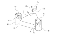
- the spacer 13 may have a shape that can define the arrangement position of the cylindrical member 25. More specifically, as shown in FIG. 7, a cutout portion 13 a formed in a cutout shape that defines the arrangement position of the cylindrical member 25 is provided at the peripheral portion of the spacer 13.
- the shape of the notch 13a is not particularly limited, and is formed by a curved surface or a plurality of flat surfaces.
- This spacer 13 is formed using materials, such as resin and a polystyrene foam, for example.
- materials such as resin and a polystyrene foam, for example.
- a part or all of the notch portion 13a may be formed as a fitting groove portion formed in a groove shape (not shown).
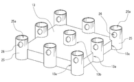
- the spacer 13 may be shaped as shown in the schematic perspective view of FIG. More specifically, as shown in FIG. 9, the spacer 13 is provided with a notch 13 a formed in a notch that defines the arrangement position of the cylindrical member 25 at the peripheral edge. Furthermore, a fitting groove portion 13b formed in a groove shape into which the cylindrical member 25 can be fitted is provided in the central portion of the spacer 13. For example, the fitting groove 13 b has an inner diameter that is the same as the outer diameter of the tubular member 25.
- a part or all of the notch portion 13a may be formed as a fitting groove portion formed in a groove shape (not shown).
- a plurality of cylindrical members 25 can be juxtaposed in a minimum number. Therefore, the cost of the intermediate structure and the platen 10 can be further reduced. Further, by providing the spacer 13, it becomes easy to arrange the cylindrical members 25 side by side, so that the platen 10 can be manufactured easily and at low cost. Furthermore, when the cylindrical member 25 is formed using, for example, a resin material, the outer peripheral portion is so-called thicker than that formed using a metal material (that is, the difference between the inner diameter and the outer diameter is larger). However, in the case of such a thick structure, since the solid region is larger than in the case of the thin structure, the region may block the suction hole 12 of the upper panel 11. Get higher.
- the space between the upper panel 11 and the lower panel 21 is a closed space that can be sealed.
- This closed space is formed by sealing the outer periphery of the platen 10, that is, the outer periphery of the upper panel 11 and the lower panel 21 joined via the cylindrical member 25 with a resin material (not shown) such as rubber.
- air suction means 23 for sucking air in the closed space is provided.
- the air suction means 23 for example, a vacuum pump, an air compressor, or the like can be used.
- a pump hole 22 penetrating the lower panel 21 is formed at the center of the lower panel 21, and a suction tube 24 connected to the vacuum pump 23 is connected to the pump hole 22.
- the present invention is not limited to this.
- the first hole 12 of the upper panel 11 is disposed at a position that closes the opening 25 a of the cylindrical member 25 in the upper panel 11. ing. Furthermore, the cylindrical member 25 is provided with a second hole portion 26 penetrating inward and outward on the side surface.
- the inside of a closed space is made into negative pressure by providing the through-hole (2nd hole part) 26 in the side surface of the cylindrical member 25, the inside of the cylindrical member 25 is also made into negative pressure. can do. Therefore, in the upper panel 11, it is possible to dispose the suction hole (first hole) 12 capable of sucking air at a position corresponding to the opening 25 a of the cylindrical member 25. The degree of freedom of the arrangement positions of 12 can be improved.
- the second hole portion 26 of the cylindrical member 25 is provided at a position that does not interfere with the side surface of the spacer 13 (see FIG. 7). If the second hole portion 26 of the cylindrical member 25 interferes with the side surface of the spacer 13, even if the inside of the closed space has a negative pressure, the inside of the cylindrical member 25 cannot be a negative pressure. The subject that it becomes impossible to generate
- the cylindrical members 25 are arranged side by side, it is not necessary to adjust the orientation of the cylindrical members 25 so that the second holes 26 are not blocked by the side surfaces of the spacers 13. The parallel work is facilitated, and the platen 10 can be manufactured easily and at low cost.
- the suction hole (first hole) 12 may not be provided at a position corresponding to the opening 25 a of the tubular member 25 in the upper panel 11. In that case, it is good also as a structure which does not provide the 2nd hole part 26 in the side surface of the cylindrical member 25. FIG. According to this configuration, the manufacturing cost of the cylindrical member 25 can be reduced.
- the medium support apparatus is lightweight, low-cost, and highly accurate. Is possible. Further, by applying the medium support apparatus (platen 10) to a medium processing apparatus (for example, the print cutting apparatus 1), it is possible to process the medium with high accuracy.
- the disclosed platen 10 includes a plurality of cylindrical members 25 arranged in parallel at predetermined intervals so that the openings 25a face the same direction, and an upper panel 11 joined to the cylindrical member 25 so as to close the openings 25a. It is characterized by providing. According to this, instead of the conventional honeycomb structure, a plurality of tubular members 25 can be used as the intermediate structure bonded to the upper panel 11. Therefore, there is no need for a step of cutting (or forming) a thin plate made of an aluminum alloy or the like necessary for forming the honeycomb structure, or a step of laminating and extending the thin plate while intermittently bonding the thin plate.
- the intermediate structure can be formed at a very low cost, and the cost of the platen 10 can be reduced. Further, it is possible to easily achieve high accuracy of the platen 10 only by forming each cylindrical member 25 within a predetermined accuracy range. Further, the platen 10 can be reduced in weight by forming the cylindrical member 25 using, for example, a resin material.
- the lower panel 21 provided facing the upper panel 11 is provided, the upper panel 11 has the 1st hole part (adsorption hole) 12 penetrated in the front and back, and the some cylindrical member 25 is upper part. It is preferable to be disposed in a closed space formed between the panel 11 and the lower panel 21. According to this, by using the air suction means 23 to create a negative pressure in the closed space, an action of sucking air in the direction toward the closed space into the suction hole 12 is obtained, and the medium is placed on the upper panel 11. It can be adsorbed and supported.
- the upper panel 11 has the 1st hole part (adsorption hole) 12 penetrated in the front and back in the position which blocks the opening part 25a of the cylindrical member 25, and the cylindrical member 25 penetrates in and out on the side. It is preferable to have the 2nd hole part 26 to do. According to this, by providing the second hole portion 26 on the side surface of the cylindrical member 26, when the inside of the closed space is set to a negative pressure, the inside of the cylindrical member 25 can also be set to a negative pressure. Therefore, in the upper panel 11, the suction hole 12 can be formed at a position corresponding to the opening 25a of the cylindrical member 25, so that the degree of freedom of the position of the suction hole 12 can be improved.
- the suction hole 12 can be formed at a position corresponding to the opening 25a of the cylindrical member 25, so that the degree of freedom of the position of the suction hole 12 can be improved.
- a spacer 13 that juxtaposes a plurality of cylindrical members 25 at equal intervals.
- a plurality of cylindrical members 25 can be juxtaposed in a minimum number so that the deformation amount of the upper panel 11 is allowed. Therefore, the cost of the intermediate structure and the platen 10 can be further reduced.
- the spacer 13 it becomes easy to arrange the cylindrical members 25 side by side, so that the platen 10 can be manufactured easily and at low cost.
- the cylindrical member 25 is formed using, for example, a resin material
- the outer peripheral portion is so-called thicker than that formed using a metal material (that is, the difference between the inner diameter and the outer diameter is larger).
- the second hole 26 of the cylindrical member 25 is preferably provided at a position that does not interfere with the side surface of the spacer 13. If the second hole portion 26 of the cylindrical member 25 interferes with the side surface of the spacer 13, even if the inside of the closed space has a negative pressure, the inside of the cylindrical member 25 cannot be a negative pressure. The subject that it becomes impossible to generate
- the cylindrical members 25 are arranged side by side, it is not necessary to adjust the orientation of the cylindrical members 25 so that the second holes 26 are not blocked by the side surfaces of the spacers 13. The parallel work is facilitated, and the platen 10 can be manufactured easily and at low cost.
- the disclosed print cutting apparatus 1 includes the platen 10 and air suction means 23 for sucking air in the closed space. According to this, it is possible to process the medium with high accuracy by applying the platen 10 that is lightweight, low-cost, and can be formed with high accuracy, and is lightweight and low-cost. It is possible to realize a print cutting apparatus. In particular, it is suitable for application to a large flat bed type apparatus.
- the present invention is not limited to the embodiments described above, and various modifications can be made without departing from the present invention.
- the print cutting apparatus has been described as an example of a medium processing apparatus including a medium support apparatus (platen).
- the present invention is not limited to this, and the present invention is not limited to this.
- the present invention can also be applied to other medium processing devices such as a cutting device that performs only cutting processing, a device that performs cutting processing on a medium, and a device that performs ruled processing.
Landscapes
- Engineering & Computer Science (AREA)
- Mechanical Engineering (AREA)
- Life Sciences & Earth Sciences (AREA)
- Forests & Forestry (AREA)
- General Engineering & Computer Science (AREA)
- Handling Of Sheets (AREA)
- Coating Apparatus (AREA)
- Handling Of Cut Paper (AREA)
Description
本発明は、媒体支持装置および媒体加工装置に関し、さらに詳細には、媒体に対して印刷、カット等の加工を行う際に当該媒体を支持するための媒体支持装置、および当該媒体支持装置を備えた媒体加工装置に関する。
上記媒体加工装置として、例えば、媒体に対して印刷を行うインクジェットプリント装置、あるいは媒体に対してカット加工を行うカッティング装置等が挙げられる。
より詳しくは、従来より、プラテン(媒体支持装置)に支持されたシート状の媒体に対して、インクを吐出するインクジェットヘッドを搭載した印刷ユニットを左右に往復移動させる作動と媒体を前後に送る作動とを組み合わせて行うことにより、媒体に所望画像を印刷可能なインクジェットプリント装置が知られている。一方、プラテンに支持されたシート状の媒体に対して、カッタ刃を有するカッティングヘッドを搭載したカッティングユニットを左右に往復移動させる作動と媒体を前後に送る作動とを組み合わせて行うことにより、媒体に所望のカット加工を施すことが可能なカッティング装置も知られている。例えば、台紙とシール紙とが貼り合わされた媒体を用いて上記インクジェットプリント装置により所望画像を印刷し、その媒体に対して上記カッティング装置により所望画像の輪郭に沿ってカット加工を施すことで、様々な模様および形状のシールを作成することができる。また、上記インクジェットプリント装置にカッティングユニットを追加して搭載し、印刷およびカット加工が一つの装置で行えるように構成されたプリント・カッティング装置も開発されている(特許文献1参照)。
上記に例示される媒体加工装置においては、媒体の加工(例えば、印刷、カット加工)を行う場合、印刷位置あるいはカット位置に関して高精度の位置決めが要求される。特に、媒体の加工を行う際に当該媒体を支持するための媒体支持装置としてのプラテン(以下、単に「プラテン」という)に対しては、歪み等がないように高精度に形成されていることが非常に重要となる。
従来のプラテンは、例えば、フラットベッド型のインクジェットプリント装置の場合、下部パネルと、当該下部パネルに中間構造体を介して接合される上部パネルとを備えて構成される。さらに、上部パネルには多数の吸着孔が設けられると共に、下部パネルと上部パネルとの間に形成された閉空間内の空気を吸引する空気吸引手段が設けられる構成のものもある。この構成によれば、空気吸引手段により当該閉空間内の空気を吸引すると、上部パネルの吸着孔から空気が吸引されるため、媒体を上部パネルに吸着させる作用を得ることができる。
ここで、上記のプラテンを構成する中間構造体の例として、従来、ハニカム構造体が用いられていた(図11参照)。一例として、アルミニウム合金、あるいは高分子フィルムが接合されたカーボングラファイトシート等の材料からなる薄い板状部材を間欠的に接着しながら積層し、当該積層体を積層方向に引き延ばすことによって形成されるハニカム構造体が知られている(特許文献2参照)。
しかし、上記に例示されるプラテンの中間構造体は、アルミニウム合金等からなる薄板を所定形状に切断(もしくは成形)する工程や、当該薄板を間欠的に接着しながら積層して引き延ばす工程を備えて形成されるハニカム構造体であるため、それらの工程を精度よく実施して、高精度のハニカム構造体を得るためには非常にコストがかかるという課題があった。
さらに、上部パネルに多数の吸着孔が設けられるプラテンの場合には,当該吸着孔と中間構造体(ハニカム構造体)が干渉することがあり、吸着孔がハニカム構造体によって塞がれてしまうことにより、媒体吸着力が偏ってしまうという課題があった。
本発明は、上記課題に鑑みてなされたものであり、媒体支持面の面積が大きい場合であっても、軽量であると共に低コストで、且つ高精度に形成することが可能な媒体支持装置および当該媒体支持装置を備えた媒体加工装置を提供することを目的とする。
一実施形態として、以下に開示するような解決手段により、前記課題を解決する。
開示の媒体支持装置は、開口部が同一方向を向くように所定間隔で並設された複数の筒状部材と、前記開口部を塞ぐように前記筒状部材に接合された第1の板状部材と、を備えることを特徴とする。これによれば、第1の板状部材に接合される中間構造体として、従来のハニカム構造体に代えて、複数の筒状部材を用いることができる。したがって、ハニカム構造体の形成に必要であったアルミニウム合金等からなる薄板を所定形状に切断(もしくは成形)する工程や、当該薄板を間欠的に接着しながら積層して引き延ばす工程が不要となるため、中間構造体の形成を非常に低コストで行うことが可能となり、プラテンの低コスト化が実現し得る。また、各筒状部材(特に軸線方向寸法)を所定の精度範囲内に形成するだけで、プラテンの高精度化を容易に達成することが可能となる。さらに、筒状部材を、例えば樹脂材料を用いて形成することにより、プラテンの軽量化も可能となる。
また、本発明において、前記第1の板状部材に対向して設けられた第2の板状部材を備え、前記第1の板状部材は、表裏に貫通する第1の孔部を有し、前記複数の筒状部材は、前記第1の板状部材と、前記第2の板状部材との間に形成された閉空間内に配設されていることが好ましい。なお、閉空間は、プラテンの外周をゴム等の樹脂材料で封止することによって形成される。これによれば、空気吸引手段を用いて閉空間内を負圧にすることによって、第1の孔部において閉空間内へ向かう方向に空気を吸引する作用が得られ、媒体を第1の板状部材上に吸着させて支持することが可能となる。
また、本発明において、前記第1の板状部材は、前記筒状部材の開口部を塞ぐ位置に、表裏に貫通する第1の孔部を有し、前記筒状部材は、側面に、内外に貫通する第2の孔部を有することが好ましい。これによれば、筒状部材の側面に貫通孔(第2の孔部)を設けることによって、閉空間内を負圧にした場合に、筒状部材の内部も負圧にすることができる。したがって、第1の板状部材において、筒状部材の開口部に対応する位置にも吸着孔(第1の孔部)を設けることが可能となるため、当該吸着孔の配設位置の自由度を向上させることができる。
また、本発明において、前記複数の筒状部材を等間隔で並設させるスペーサを備えることが好ましい。これによれば、第1の板状部材において変形量が許容される程度に、複数の筒状部材を最小個数で並設させることが可能となる。したがって、中間構造体ひいてはプラテンの一層の低コスト化が可能となる。また、スペーサを設けることで、筒状部材の並設作業が容易となるため、プラテンの製造を容易且つ低コストに行うことが可能となる。さらに、筒状部材を、例えば樹脂材料を用いて形成する場合には、金属材料を用いて形成する場合と比較して、外周部がいわゆる厚肉に(すなわち内径と外径との差が大きく)なることが想定されるが、そのような厚肉構造の場合、薄肉構造の場合よりも、中実領域が大きいため、当該領域が吸着孔を塞いでしまう可能性が高くなってしまう課題がある。しかし、上記の通り、筒状部材を最小個数で並設させることが可能となれば、吸着孔を塞いでしまうことを回避し易くなり、吸着孔が塞がれてしまうことによって生じる媒体吸着力のアンバランスを防止でき、媒体加工精度を高めることが可能となる。
また、本発明において、前記筒状部材の第2の孔部は、前記スペーサの側面と干渉しない位置に設けられることが好ましい。仮に、筒状部材の第2の孔部がスペーサの側面と干渉してしまうと、閉空間内を負圧にしても筒状部材の内部を負圧にすることができないため、筒状部材の開口部内に位置する吸着孔に吸着力を発生させることができなくなってしまう課題が生じる。これに対して、上記構成によれば、第2の孔部とスペーサの側面とが干渉しないため、当該課題の防止が可能となる。さらに、筒状部材の並設作業を行う際に、第2の孔部がスペーサの側面によって塞がれてしまわないように筒状部材の向きを調整する作業が不要となるため、当該並設作業が容易となり、プラテンの製造を容易且つ低コストに行うことが可能となる。
開示の媒体加工装置は、前記媒体支持装置と、前記閉空間内の空気を吸引する空気吸引手段と、を備えることを特徴とする。これによれば、軽量であると共に低コストで、且つ高精度に形成することが可能な前記の媒体支持装置を適用することによって、高精度に媒体の加工を行うことができ、且つ軽量で低コストの媒体加工装置の実現が可能となる。特に、大型のフラットベッド型の装置への適用において好適である。
開示の媒体支持装置によれば、媒体支持面の面積が大きい場合であっても、軽量であると共に低コストで、且つ高精度に形成することが可能となる。また当該媒体支持装置を媒体加工装置に適用することによって、高精度に媒体の加工を行うことが可能となる。
以下、図面を参照して、本発明の実施形態について詳しく説明する。ここでは、本実施形態に係る媒体支持装置が組み込まれる媒体加工装置として、フラットベッド型のプリント・カッティング装置の場合を例に挙げて説明を行う。なお、実施形態を説明するための全図において、同一の機能を有する部材には同一の符号を付し、その繰り返しの説明は省略する場合がある。
図1に、本実施形態に係る媒体支持装置(プラテン10)を備えるプリント・カッティング装置1の概略斜視図を示す。また、図2に、当該プリント・カッティング装置1の概略背面図を示す。なお、説明の便宜上、図1、図2において矢印方向でプリント・カッティング装置1の前後、左右、および上下方向を示す。また、図2における紙面の前後方向をプリント・カッティング装置1の前後方向とする。
本実施形態に係るプリント・カッティング装置1は、インクジェットヘッド60とカッティングヘッド50とを備えて構成され、プラテン10によって支持されたシート状の媒体に対して、印刷のみを行う動作、カット加工のみを行う動作、および印刷とその印刷画像に対応させたカット加工とをまとめて行う動作のうちから、目的に応じて選択された動作を行う装置である。
プリント・カッティング装置1は、全体構成として、第1のサブアセンブリ3の上方に第2のサブアセンブリ4が組み付けられて構成されている。
ここで、第1のサブアセンブリ3は、加工対象物である媒体を支持するプラテン10の左右に、前後に延びる前後移動機構17、17が設けられて構成される。なお、プラテン10の下側には電源および制御機器類18が配設される。
また、第2のサブアセンブリ4は、左右に延びる長尺状のガイドバー部材40に沿って左右に移動可能にインクジェットヘッド60およびカッティングヘッド50が取り付けられると共に、インクジェットヘッド60およびカッティングヘッド50を左右に移動させる左右移動機構30(図3Aおよび図3B参照)が設けられて構成される。また、ガイドバー部材40の左端部および右端部には、それぞれインク供給装置70およびメンテナンスユニット80が取り付けられて構成される。
ここで、第1のサブアセンブリ3は、加工対象物である媒体を支持するプラテン10の左右に、前後に延びる前後移動機構17、17が設けられて構成される。なお、プラテン10の下側には電源および制御機器類18が配設される。
また、第2のサブアセンブリ4は、左右に延びる長尺状のガイドバー部材40に沿って左右に移動可能にインクジェットヘッド60およびカッティングヘッド50が取り付けられると共に、インクジェットヘッド60およびカッティングヘッド50を左右に移動させる左右移動機構30(図3Aおよび図3B参照)が設けられて構成される。また、ガイドバー部材40の左端部および右端部には、それぞれインク供給装置70およびメンテナンスユニット80が取り付けられて構成される。
先ず、プラテン10の構成について説明する。
プラテン10は、図1、5に示すように、床面に対して支持固定を行う複数の脚16、16、・・・と、加工対象物である媒体が載置されてその支持を行う第1の板状部材(以下、「上部パネル」という)11と、中間構造体25を介して上部パネル11を支持する第2の板状部材(以下、「下部パネル」という)21とを有している。ここで、上部パネル11は、床面上の所定高さ位置に配設されている。また、上部パネル11には表裏に貫通(厚さ方向に貫通)する複数の孔部(以下、「第1の孔部」という)12が設けられている。この構成によれば、空気吸引手段23を用いて第1の孔部12の表面から裏面へ空気を吸引することによって、媒体を上部パネル11上に吸着させて支持することが可能となる(詳しくは後述する)。
ここで、ガイドバー部材40は、プラテン10の上方に配設されるが、左右長さがプラテン10よりも長く形成されているため、当該ガイドバー部材40の左右端部40a、40bがプラテン10に対して左右に突出する構造となっている。
プラテン10は、図1、5に示すように、床面に対して支持固定を行う複数の脚16、16、・・・と、加工対象物である媒体が載置されてその支持を行う第1の板状部材(以下、「上部パネル」という)11と、中間構造体25を介して上部パネル11を支持する第2の板状部材(以下、「下部パネル」という)21とを有している。ここで、上部パネル11は、床面上の所定高さ位置に配設されている。また、上部パネル11には表裏に貫通(厚さ方向に貫通)する複数の孔部(以下、「第1の孔部」という)12が設けられている。この構成によれば、空気吸引手段23を用いて第1の孔部12の表面から裏面へ空気を吸引することによって、媒体を上部パネル11上に吸着させて支持することが可能となる(詳しくは後述する)。
ここで、ガイドバー部材40は、プラテン10の上方に配設されるが、左右長さがプラテン10よりも長く形成されているため、当該ガイドバー部材40の左右端部40a、40bがプラテン10に対して左右に突出する構造となっている。
次に左右移動機構30の構成について説明する。
第2のサブアセンブリ4に設けられる左右移動機構30は、図3Aおよび図3B(図3Aは概略平面図であり、図3Bは概略背面図である)に示すように、駆動スプロケット31と、従動スプロケット32と、駆動スプロケット31および従動スプロケット32に掛け回される歯付ベルト33と、カッティングヘッド50およびインクジェットヘッド60を繋ぐ連結部材34とを有して構成される。ここで、歯付ベルト33は、その一端33aがインクジェットヘッド60に取り付けられる共に、その他端33bがカッティングヘッド50に取り付けられている。また、連結部材34は、その一端34aがインクジェットヘッド60に取り付けられる共に、その他端34bがカッティングヘッド50に取り付けられている。なお、連結部材34を用いずに、カッティングヘッド50およびインクジェットヘッド60を一体に歯付ベルト33に取り付ける構成としてもよい。
第2のサブアセンブリ4に設けられる左右移動機構30は、図3Aおよび図3B(図3Aは概略平面図であり、図3Bは概略背面図である)に示すように、駆動スプロケット31と、従動スプロケット32と、駆動スプロケット31および従動スプロケット32に掛け回される歯付ベルト33と、カッティングヘッド50およびインクジェットヘッド60を繋ぐ連結部材34とを有して構成される。ここで、歯付ベルト33は、その一端33aがインクジェットヘッド60に取り付けられる共に、その他端33bがカッティングヘッド50に取り付けられている。また、連結部材34は、その一端34aがインクジェットヘッド60に取り付けられる共に、その他端34bがカッティングヘッド50に取り付けられている。なお、連結部材34を用いずに、カッティングヘッド50およびインクジェットヘッド60を一体に歯付ベルト33に取り付ける構成としてもよい。
また、駆動スプロケット31および従動スプロケット32は、それぞれがプラテン10の左端部と右端部において回転自在に支持されている。この駆動スプロケット31は、シャフト35を介して駆動モータ(不図示)に連結され、当該駆動モータの回転駆動力により回転可能に構成されている。
さらに、カッティングヘッド50の内部には、いずれも上下方向を回転軸とする前後一対のガイドローラ42、43が左右に間隔を置いて二組取り付けられている。この前後一対のガイドローラ42,43は、ガイドバー部材40において左右に水平に延びるように配設されたガイドレール41を前後に挟持して転動可能に取り付けられている。この構成により、カッティングヘッド50は、ガイドレール41に沿って左右に移動可能となる。
また、インクジェットヘッド60の内部には、いずれも上下方向を回転軸とする前後一対のガイドローラ44、45が左右に間隔を置いて二組取り付けられている。この前後一対のガイドローラ44、45は、ガイドレール41を前後に挟持するように取り付けられている。この構成により、インクジェットヘッド60は、ガイドレール41に沿って左右に移動可能となる。
また、インクジェットヘッド60の内部には、いずれも上下方向を回転軸とする前後一対のガイドローラ44、45が左右に間隔を置いて二組取り付けられている。この前後一対のガイドローラ44、45は、ガイドレール41を前後に挟持するように取り付けられている。この構成により、インクジェットヘッド60は、ガイドレール41に沿って左右に移動可能となる。
このように構成された左右移動機構30によれば、駆動モータを駆動させることにより、シャフト35を介して駆動スプロケット31が回転駆動されて歯付ベルト33が左右移動し、歯付ベルト33に取り付けられたカッティングヘッド50およびインクジェットヘッド60の双方が、両者を繋ぐ連結部材34によってこれらの間隔を保持しつつガイドレール41により案内されながら左右に移動する作用が得られる。
次に、カッティングヘッド50の構成について説明する。
本実施形態に係るカッティングヘッド50は、その下部に、下方に突出して加工対象物である媒体の表面に切り込みを入れる(媒体の台紙には切り込みを入れずに接着剤の付いた表面のシール部分のみ所定の形状に切り込みを入れる)ためのカッタ51が上下動可能に取り付けられている(図3B参照)。なお、カッタ51による切り込み動作は、上記のように媒体の表面にのみ切り込みを入れる動作の他に、媒体の台紙も含めて切断することによって切り離しを行う動作とすることもできる。
本実施形態に係るカッティングヘッド50は、その下部に、下方に突出して加工対象物である媒体の表面に切り込みを入れる(媒体の台紙には切り込みを入れずに接着剤の付いた表面のシール部分のみ所定の形状に切り込みを入れる)ためのカッタ51が上下動可能に取り付けられている(図3B参照)。なお、カッタ51による切り込み動作は、上記のように媒体の表面にのみ切り込みを入れる動作の他に、媒体の台紙も含めて切断することによって切り離しを行う動作とすることもできる。
次に、インクジェットヘッド60の構成について説明する。
本実施形態に係るインクジェットヘッド60は、左右に並ぶ複数のインクジェットノズル(以下、「ノズル」と称する)61、61、・・・を有して構成されており(図4A参照)、それぞれのノズル61、61、・・・には、インク通路62が噴射開口62aを下方に開放して形成されている(図4B参照)。ここで、図4Aは複数のノズル61の構成例を示す概略図であり、図4Bはノズル61の先端周辺の構成例を示す概略図である。
本実施形態に係るインクジェットヘッド60は、左右に並ぶ複数のインクジェットノズル(以下、「ノズル」と称する)61、61、・・・を有して構成されており(図4A参照)、それぞれのノズル61、61、・・・には、インク通路62が噴射開口62aを下方に開放して形成されている(図4B参照)。ここで、図4Aは複数のノズル61の構成例を示す概略図であり、図4Bはノズル61の先端周辺の構成例を示す概略図である。
また、ガイドバー部材40の右端部40aには、インク通路62にインクを供給するためのインク供給装置70が設けられると共に、カッティングヘッド50およびインクジェットヘッド60の移動制御やインクジェットヘッド60におけるインクの噴射制御を行うための制御装置(不図示)が設けられている(図2参照)。
一方、ガイドバー部材40の左端部40bには、当該左端部40bを覆うハウジング80aが設けられると共に、その内部にメンテナンスユニット80が設けられている。このメンテナンスユニット80は、インク通路62の内部に残留するインクを吸引したり、噴射開口62aの周辺に付着しているインク滓やゴミ等を取り除いたりして、噴射開口62aからインクが正常に噴射される状態に回復させるための機構である。また、メンテナンスユニット80の下方には、廃インクタンク90が設けられており、メンテナンスユニット80において処理されたインクを貯留することが可能となっている。
一方、ガイドバー部材40の左端部40bには、当該左端部40bを覆うハウジング80aが設けられると共に、その内部にメンテナンスユニット80が設けられている。このメンテナンスユニット80は、インク通路62の内部に残留するインクを吸引したり、噴射開口62aの周辺に付着しているインク滓やゴミ等を取り除いたりして、噴射開口62aからインクが正常に噴射される状態に回復させるための機構である。また、メンテナンスユニット80の下方には、廃インクタンク90が設けられており、メンテナンスユニット80において処理されたインクを貯留することが可能となっている。
次に、駆動・制御の配線等の構成について説明する。
本実施形態においては、図2に示すように、プラテン10の右側下部とインク供給装置70とを繋ぐ第1フレキシブルケーブルガイド15(例えば、ケーブルベア(登録商標))が設けられている。この第1フレキシブルケーブルガイド15の内部には、プラテン10に配設された電源および制御機器類18から第2のサブアセンブリ4側の装置類を駆動制御するための電力や制御信号を供給するための電線が配設されている。これによれば、プラテン10に対するガイドバー部材40の前後移動を許容しつつ、第1のサブアセンブリ3側から第2のサブアセンブリ4側に電力や制御信号を供給することができる。
本実施形態においては、図2に示すように、プラテン10の右側下部とインク供給装置70とを繋ぐ第1フレキシブルケーブルガイド15(例えば、ケーブルベア(登録商標))が設けられている。この第1フレキシブルケーブルガイド15の内部には、プラテン10に配設された電源および制御機器類18から第2のサブアセンブリ4側の装置類を駆動制御するための電力や制御信号を供給するための電線が配設されている。これによれば、プラテン10に対するガイドバー部材40の前後移動を許容しつつ、第1のサブアセンブリ3側から第2のサブアセンブリ4側に電力や制御信号を供給することができる。
また、ガイドバー部材40の右端部40aとカッティングヘッド50とを繋ぐ第2フレキシブルケーブルガイド65が設けられている。この第2フレキシブルケーブルガイド65の内部には、制御機器類18からカッティングヘッド50のカッタ51を上下に移動制御したりインクジェットヘッド60のノズル61を上下に移動制御するための電力や制御信号を供給するための電線や、インク供給装置70からカッティングヘッド50を介してインクジェットヘッド60にインクを供給するためのチューブが配設されている。これによれば、インク供給装置70側からカッティングヘッド50側に電力および制御信号やインクを供給することができる。
さらに、カッティングヘッド50とインクジェットヘッド60とを繋いで第3フレキシブルケーブルガイド66が設けられている。この第3フレキシブルケーブルガイド66の内部には、制御機器類18からインクジェットヘッド60のノズル61を上下に移動制御するための電力や制御信号を供給するための電線や、インク供給装置70からインクジェットヘッド60にインクを供給するためのチューブが配設されている。これによれば、カッティングヘッド50側からインクジェットヘッド60側に電力および制御信号やインクを供給することができる。
以上説明した構成を備えることによって、本実施形態に係るプリント・カッティング装置1は、媒体に印刷のみを行う動作、カット加工のみを行う動作、および印刷とその印刷画像に対応させたカット加工とをまとめて行う動作のうちから、目的に応じて選択された動作を実行させることが可能となる。
例えば、印刷とカット加工とをまとめて行う動作について説明すると、先ず、ガイドバー部材40をプラテン10に対して前後に移動させると共に、噴射開口62aをプラテン10に保持された媒体の表面に対向させながらインクジェットヘッド60を前後左右に移動させる。この移動時に噴射開口62aからインクが噴射され、媒体の上面に所望の文字や図柄が印刷される。次いで、ガイドバー部材40をプラテン10に対して前後に移動させると共に、カッティングヘッド50の下部に設けられたカッタ51の刃先をプラテン10に保持された媒体の表面に向けながらカッティングヘッド50を前後左右に移動させて、媒体の所望の位置における媒体の表面がカット加工される。このように、所望画像の印刷とカット加工とを、媒体をプラテン10からその都度取り外すことなく連続して行うことができる点で非常に効率的である。
例えば、印刷とカット加工とをまとめて行う動作について説明すると、先ず、ガイドバー部材40をプラテン10に対して前後に移動させると共に、噴射開口62aをプラテン10に保持された媒体の表面に対向させながらインクジェットヘッド60を前後左右に移動させる。この移動時に噴射開口62aからインクが噴射され、媒体の上面に所望の文字や図柄が印刷される。次いで、ガイドバー部材40をプラテン10に対して前後に移動させると共に、カッティングヘッド50の下部に設けられたカッタ51の刃先をプラテン10に保持された媒体の表面に向けながらカッティングヘッド50を前後左右に移動させて、媒体の所望の位置における媒体の表面がカット加工される。このように、所望画像の印刷とカット加工とを、媒体をプラテン10からその都度取り外すことなく連続して行うことができる点で非常に効率的である。
ここで、本実施形態に特徴的なプラテン10の構成について詳細に説明する。
図5の概略斜視図に示すように、プラテン10は、下部パネル21と、当該下部パネル21に中間構造体25を介して接合される上部パネル11とを備えて構成される。本実施形態においては、上部パネル11と下部パネル21とは平行になるように相互に対向して配設され、ネジ止めにより固定される。ここで、上部パネル11および下部パネル21は、いずれも平板状の部材(当該部材にはシート状材料を平板状に展開したものも含まれる)を用いて構成される。なお、当該平板状の部材には、単層構造、積層構造のいずれも採用することができる。一例として、大型のフラットベッド型の装置の場合、上部パネル11、下部パネル21の寸法は、長さ:3000[mm]×幅:1600[mm]程度に形成される。
図5の概略斜視図に示すように、プラテン10は、下部パネル21と、当該下部パネル21に中間構造体25を介して接合される上部パネル11とを備えて構成される。本実施形態においては、上部パネル11と下部パネル21とは平行になるように相互に対向して配設され、ネジ止めにより固定される。ここで、上部パネル11および下部パネル21は、いずれも平板状の部材(当該部材にはシート状材料を平板状に展開したものも含まれる)を用いて構成される。なお、当該平板状の部材には、単層構造、積層構造のいずれも採用することができる。一例として、大型のフラットベッド型の装置の場合、上部パネル11、下部パネル21の寸法は、長さ:3000[mm]×幅:1600[mm]程度に形成される。
下部パネル21は、中間構造体25を介して上部パネル11を支持するものであり、床面上の所定の高さ位置に保持されている。一例として、下部パネル21は、アルミニウムもしくはアルミニウム合金によって、所定厚さの平板矩形状に形成されている。
一方、上部パネル11は、加工対象物である媒体を載置してその支持を行うものである。一例として、下部パネル21は、アルミニウムもしくはアルミニウム合金によって、所定厚さの平板矩形状に形成されている。本実施形態に係る上部パネル11は、後述の媒体吸着作用を生じさせるため、表裏に貫通(厚さ方向に貫通)する複数の孔部(第1の孔部)12が設けられている。
ここで、中間構造体25として、複数の筒状部材が用いられる。本実施形態においては、下部パネル21上に複数の筒状部材25が、開口部25aが同一方向を向くように所定間隔で並設され、当該開口部を塞ぐように上部パネル11が各筒状部材に接合される構成を有している。形成方法の例としては、先ず、下部パネル21を敷設し、複数の筒状部材25を熱可塑性のある接着材で固定していく。次いで、筒状部材25の上端にも熱可塑性のある接着材を塗布して上部パネル11を被せる。最後に、媒体加工面の精度を確保するためヒータを内蔵したローラなどで上部パネル11の上面に押圧を与えて形成を行う。
なお、筒状部材25は、円筒に限らず、断面が六角形や八角形、四角形等の筒でもよい。一例として、塩化ビニル等の樹脂材料を用いて形成されるが、これに限定されるものではなく、アルミニウム合金等の金属材料を用いてもよい。このように樹脂材料等の軽量材料を用いることにより、プラテン10の軽量化が可能となる。
上記の構成によれば、中間構造体として、従来のハニカム構造体に代えて、複数の筒状部材25を用いることができる。したがって、ハニカム構造体の形成に必要であったアルミニウム合金等からなる薄板を所定形状に切断(もしくは成形)する工程や、当該薄板を間欠的に接着しながら積層して引き延ばす工程が不要となるため、非常に低コストで中間構造体を形成することが可能となり、プラテン10の低コスト化が実現できる。また、各筒状部材25(特に、軸線方向寸法)を所定の精度範囲内に形成するだけで、プラテン10の高精度化を容易に達成することが可能となる。さらに、塩化ビニル等の樹脂材料を用いて形成されることによって、プラテン10の軽量化を図ることが可能となる。なお、筒状部材25を樹脂成型により製造する場合には、一本ずつの成型、あるいは複数本まとめての成型の何れであってもよい。
ここで、本実施形態においては、複数の筒状部材25を等間隔で間隔を空けて並設させるスペーサ13が設けられる。このときの間隔は、上部パネル11を筒状部材25上に載置したときに当該上部パネル11に生じる変形量が所定の許容範囲内となるように設定することが好適である。
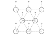
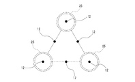
筒状部材25の並設構造の例として、図6に示すように、複数の筒状部材25をその中心位置が正三角形の配置となるように等間隔で並設する構成とすればよい。この配置によれば、当該筒状部材25の所要数を最小個数とすることができる。この場合、スペーサ13は、図7の概略斜視図に示すように、筒状部材25の配置位置さえ規定できる形状であればよい。より詳しくは、同図7に示すように、スペーサ13の周縁部に筒状部材25の配置位置を規定する切欠状に形成された切欠部13aが設けられている。切欠部13aの形状は特に限定されるものではなく、曲面あるいは複数の平面等によって形成される。このスペーサ13は、例えば、樹脂や発泡スチロール等の材料を用いて形成される。
なお、切欠状に形成された切欠部13aに代えて、その一部もしくは全部を、溝状に形成された嵌合溝部として形成してもよい(不図示)。
なお、切欠状に形成された切欠部13aに代えて、その一部もしくは全部を、溝状に形成された嵌合溝部として形成してもよい(不図示)。
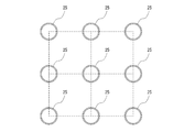
また、筒状部材25の並設構造の変形例として、図8に示すように、複数の筒状部材25をその中心位置が矩形(例えば、正方形)となるように等間隔で並設する構成としてもよい。この場合、スペーサ13は、図9の概略斜視図に示すような形状とすればよい。より詳しくは、同図9に示すように、スペーサ13の周縁部には筒状部材25の配置位置を規定する切欠状に形成された切欠部13aが設けられている。さらに、スペーサ13の中央部には筒状部材25が嵌入可能な溝状に形成された嵌合溝部13bが設けられている。例えば、嵌合溝部13bは、その内径が筒状部材25の外径と同一寸法に形成されている。
なお、切欠状に形成された切欠部13aに代えて、その一部もしくは全部を、溝状に形成された嵌合溝部として形成してもよい(不図示)。
なお、切欠状に形成された切欠部13aに代えて、その一部もしくは全部を、溝状に形成された嵌合溝部として形成してもよい(不図示)。
上記の構成によれば、複数の筒状部材25を最小個数で並設させることが可能となる。したがって、中間構造体ひいてはプラテン10の一層の低コスト化が可能となる。また、スペーサ13を設けることで、筒状部材25の並設作業が容易となるため、プラテン10の製造を容易且つ低コストに行うことが可能となる。さらに、筒状部材25を、例えば樹脂材料を用いて形成する場合には、金属材料を用いて形成する場合と比較して、外周部がいわゆる厚肉に(すなわち内径と外径との差が大きく)なることが想定されるが、そのような厚肉構造の場合、薄肉構造の場合よりも、中実領域が大きいため、当該領域が上部パネル11の吸着孔12を塞いでしまう可能性が高くなる。しかし、筒状部材を最小個数で並設させることが可能となれば、吸着孔12を塞いでしまう問題を回避し易くなり、吸着孔12が塞がれてしまうことによって生じる媒体吸着力のアンバランスを防止でき、媒体加工精度を高めることが可能となる。
また、本実施形態においては、上部パネル11と下部パネル21との間が密閉可能な閉空間となるように構成されている。この閉空間は、プラテン10の外周すなわち筒状部材25を介して接合されている上部パネル11および下部パネル21の外周をゴム等の樹脂材料(不図示)で封止することによって形成される。
また、上記の閉空間内の空気を吸引する空気吸引手段23が設けられている。空気吸引手段23として、例えば、真空ポンプ、エアコンプレッサ等を用いることができる。本実施形態においては、下部パネル21の中央部に、下部パネル21を貫通するポンプ用孔22が形成され、当該ポンプ用孔22に、真空ポンプ23に接続された吸引チューブ24が連結される構成(図5参照)としているが、これに限定されるものではない。
上記の構成によれば、空気吸引手段23を用いて閉空間内を負圧にすることによって、前記上部パネル11の第1の孔部12において表面から裏面へ向かう方向、すなわち外方から閉空間の内部へ向かう方向に空気を吸引する作用が得られ、媒体を上部パネル11上に吸着させて支持することが可能となる。
また、本実施形態に特徴的な構成として、図10に示すように、上部パネル11の第1の孔部12は、上部パネル11において筒状部材25の開口部25aを塞ぐ位置に配設されている。
さらに、筒状部材25は、側面に、内外に貫通する第2の孔部26が設けられている。
さらに、筒状部材25は、側面に、内外に貫通する第2の孔部26が設けられている。
上記の構成によれば、筒状部材25の側面に貫通孔(第2の孔部)26を設けることによって、閉空間内を負圧にした場合に、筒状部材25の内部も負圧にすることができる。したがって、上部パネル11において、筒状部材25の開口部25aに対応する位置にも空気吸引が可能な吸着孔(第1の孔部)12を配設することが可能となるため、当該吸着孔12の配設位置の自由度を向上させることができる。
ここで、筒状部材25の第2の孔部26は、スペーサ13の側面と干渉しない位置に設けられることが好ましい(図7参照)。仮に、筒状部材25の第2の孔部26がスペーサ13の側面と干渉してしまうと、閉空間内を負圧にしても筒状部材25の内部を負圧にすることができないため、筒状部材25の開口部25a内に位置する吸着孔12に吸着力を発生させることができなくなってしまう課題が生じる。これに対して、上記構成によれば、第2の孔部26とスペーサ13の側面とが干渉しないため、当該課題の解決が可能となる。さらに、筒状部材25の並設作業を行う際に、第2の孔部26がスペーサ13の側面によって塞がれてしまわないように筒状部材25の向きを調整する作業が不要となるため、当該並設作業が容易となり、プラテン10の製造を容易且つ低コストに行うことが可能となる。
なお、変形例として、上部パネル11における筒状部材25の開口部25aに対応する位置に吸着孔(第1の孔部)12を設けない構成としてもよい。
その場合には、筒状部材25の側面に、第2の孔部26を設けない構成としてもよい。この構成によれば、筒状部材25の製造コストを低減させることが可能となる。
その場合には、筒状部材25の側面に、第2の孔部26を設けない構成としてもよい。この構成によれば、筒状部材25の製造コストを低減させることが可能となる。
以上説明した通り、開示の媒体支持装置(プラテン10)によれば、媒体支持面すなわち上部パネル11の面積が大きい場合であっても、軽量であると共に低コストで、且つ高精度に形成することが可能となる。また当該媒体支持装置(プラテン10)を媒体加工装置(一例として、前記プリント・カッティング装置1)に適用することによって、高精度に媒体の加工を行うことが可能となる。
また、特に、本実施形態によって以下の特徴的な作用効果が奏される。
開示のプラテン10は、開口部25aが同一方向を向くように所定間隔で並設された複数の筒状部材25と、開口部25aを塞ぐように筒状部材25に接合された上部パネル11と、を備えることを特徴とする。これによれば、上部パネル11に接合される中間構造体として、従来のハニカム構造体に代えて、複数の筒状部材25を用いることができる。したがって、ハニカム構造体の形成に必要であったアルミニウム合金等からなる薄板を所定形状に切断(もしくは成形)する工程や、当該薄板を間欠的に接着しながら積層して引き延ばす工程が不要となるため、非常に低コストで中間構造体を形成することが可能となり、プラテン10の低コスト化が実現できる。また、各筒状部材25を所定の精度範囲内に形成するだけで、プラテン10の高精度化を容易に達成することが可能となる。さらに、筒状部材25を、例えば樹脂材料を用いて形成することにより、プラテン10の軽量化も可能となる。
また、上部パネル11に対向して設けられた下部パネル21を備え、上部パネル11は、表裏に貫通する第1の孔部(吸着孔)12を有し、複数の筒状部材25は、上部パネル11と、下部パネル21との間に形成された閉空間内に配設されていることが好ましい。これによれば、空気吸引手段23を用いて閉空間内を負圧にすることによって、吸着孔12に閉空間内へ向かう方向に空気を吸引する作用が得られ、媒体を上部パネル11上に吸着させて支持することが可能となる。
また、上部パネル11は、筒状部材25の開口部25aを塞ぐ位置に、表裏に貫通する第1の孔部(吸着孔)12を有し、筒状部材25は、側面に、内外に貫通する第2の孔部26を有することが好ましい。これによれば、筒状部材26の側面に第2の孔部26を設けることによって、閉空間内を負圧にした場合に、筒状部材25の内部も負圧にすることができる。したがって、上部パネル11において、筒状部材25の開口部25aに対応する位置にも吸着孔12が形成できるため、当該吸着孔12の配設位置の自由度を向上させることができる。
また、複数の筒状部材25を等間隔で並設させるスペーサ13を備えることが好ましい。これによれば、上部パネル11において変形量が許容される程度に、複数の筒状部材25を最小個数で並設させることが可能となる。したがって、中間構造体ひいてはプラテン10の一層の低コスト化が可能となる。また、スペーサ13を設けることで、筒状部材25の並設作業が容易となるため、プラテン10の製造を容易且つ低コストに行うことが可能となる。さらに、筒状部材25を、例えば樹脂材料を用いて形成する場合には、金属材料を用いて形成する場合と比較して、外周部がいわゆる厚肉に(すなわち内径と外径との差が大きく)なることが想定されるが、そのような厚肉構造の場合、薄肉構造の場合よりも、中実領域が大きいため、当該領域が吸着孔12を塞いでしまう可能性が高くなってしまう課題がある。しかし、上記の通り、筒状部材25を最小個数で並設させることが可能となれば、吸着孔12を塞いでしまうことを回避し易くなり、吸着孔12が塞がれてしまうことによって生じる吸着のアンバランスを防止でき、媒体加工精度を高めることが可能となる。
また、筒状部材25の第2の孔部26は、スペーサ13の側面と干渉しない位置に設けられることが好ましい。仮に、筒状部材25の第2の孔部26がスペーサ13の側面と干渉してしまうと、閉空間内を負圧にしても筒状部材25の内部を負圧にすることができないため、筒状部材25の開口部25a内に位置する吸着孔12に吸着力を発生させることができなくなってしまう課題が生じる。これに対して、上記構成によれば、第2の孔部26とスペーサ13の側面とが干渉しないため、当該課題の防止が可能となる。さらに、筒状部材25の並設作業を行う際に、第2の孔部26がスペーサ13の側面によって塞がれてしまわないように筒状部材25の向きを調整する作業が不要となるため、当該並設作業が容易となり、プラテン10の製造を容易且つ低コストに行うことが可能となる。
開示のプリント・カッティング装置1は、前記プラテン10と、前記閉空間内の空気を吸引する空気吸引手段23と、を備えることを特徴とする。これによれば、軽量であると共に低コストで、且つ高精度に形成することが可能な前記のプラテン10を適用することによって、高精度に媒体の加工を行うことができ、且つ軽量で低コストのプリント・カッティング装置の実現が可能となる。特に、大型のフラットベッド型の装置への適用において好適である。
なお、本発明は、以上説明した実施形態に限定されることなく、本発明を逸脱しない範囲において種々変更可能であることは言うまでもない。特に、媒体支持装置(プラテン)を備える媒体加工装置の例としてプリント・カッティング装置を挙げて説明したが、これに限定されるものではなく、媒体に対して印刷のみを行うプリント装置や、媒体に対してカット加工のみを行うカッティング装置、あるいは、媒体に対して切削加工を行う装置や、罫引き加工を行う装置等、その他の媒体加工装置に対しても適用が可能である。
Claims (6)
- 開口部が同一方向を向くように所定間隔で並設された複数の筒状部材と、
前記開口部を塞ぐように前記筒状部材に接合された第1の板状部材と、を備えること
を特徴とする媒体支持装置。 - 前記第1の板状部材に対向して設けられた第2の板状部材を備え、
前記第1の板状部材は、表裏に貫通する第1の孔部を有し、
前記複数の筒状部材は、前記第1の板状部材と、前記第2の板状部材との間に形成された閉空間内に配設されていること
を特徴とする請求項1記載の媒体支持装置。 - 前記第1の板状部材は、前記筒状部材の開口部を塞ぐ位置に、表裏に貫通する第1の孔部を有し、
前記筒状部材は、側面に、内外に貫通する第2の孔部を有すること
を特徴とする請求項2記載の媒体支持装置。 - 前記複数の筒状部材を等間隔で並設させるスペーサを備えること
を特徴とする請求項1記載の媒体支持装置。 - 前記筒状部材の第2の孔部は、前記スペーサの側面と干渉しない位置に設けられることを特徴とする請求項3または請求項4記載の媒体支持装置。
- 請求項1~5のいずれか一項に記載の媒体支持装置と、前記閉空間内の空気を吸引する空気吸引手段と、を備えること
を特徴とする媒体加工装置。
Priority Applications (2)
| Application Number | Priority Date | Filing Date | Title |
|---|---|---|---|
| US14/407,470 US20150122964A1 (en) | 2012-07-23 | 2013-07-22 | Medium-supporting device and medium-processing apparatus |
| CN201380030106.XA CN104349903A (zh) | 2012-07-23 | 2013-07-22 | 介质支撑装置以及介质加工装置 |
Applications Claiming Priority (2)
| Application Number | Priority Date | Filing Date | Title |
|---|---|---|---|
| JP2012162309A JP2014019121A (ja) | 2012-07-23 | 2012-07-23 | 媒体支持装置および媒体加工装置 |
| JP2012-162309 | 2012-07-23 |
Publications (1)
| Publication Number | Publication Date |
|---|---|
| WO2014017450A1 true WO2014017450A1 (ja) | 2014-01-30 |
Family
ID=49997261
Family Applications (1)
| Application Number | Title | Priority Date | Filing Date |
|---|---|---|---|
| PCT/JP2013/069833 Ceased WO2014017450A1 (ja) | 2012-07-23 | 2013-07-22 | 媒体支持装置および媒体加工装置 |
Country Status (4)
| Country | Link |
|---|---|
| US (1) | US20150122964A1 (ja) |
| JP (1) | JP2014019121A (ja) |
| CN (1) | CN104349903A (ja) |
| WO (1) | WO2014017450A1 (ja) |
Families Citing this family (5)
| Publication number | Priority date | Publication date | Assignee | Title |
|---|---|---|---|---|
| JP6530253B2 (ja) * | 2015-06-24 | 2019-06-12 | ローランドディー.ジー.株式会社 | インクジェットプリンタにおけるカッティングヘッドおよび箔押しヘッドの昇降機構 |
| JP2017178370A (ja) * | 2016-03-30 | 2017-10-05 | ローランドディー.ジー.株式会社 | パレット、加工物作製システムおよびパレットの使用方法 |
| JP7323285B2 (ja) * | 2018-12-20 | 2023-08-08 | 株式会社ミマキエンジニアリング | 加工装置 |
| JP7386044B2 (ja) * | 2019-10-30 | 2023-11-24 | セーレン株式会社 | インクジェット記録装置 |
| TWD222616S (zh) * | 2022-06-16 | 2022-12-11 | 擎宏電子企業有限公司 | 液晶顯示模組之固定座 |
Citations (5)
| Publication number | Priority date | Publication date | Assignee | Title |
|---|---|---|---|---|
| JPH10291344A (ja) * | 1997-04-18 | 1998-11-04 | Tec Corp | プラテン装置及びシリアルプリンタ |
| JP2001270176A (ja) * | 2000-02-28 | 2001-10-02 | Hewlett Packard Co <Hp> | プリント媒体真空プラテンシステム |
| JP2008055903A (ja) * | 2006-08-31 | 2008-03-13 | Oce Technologies Bv | 印刷システム |
| JP2009241370A (ja) * | 2008-03-31 | 2009-10-22 | Brother Ind Ltd | 印刷装置 |
| JP2011218668A (ja) * | 2010-04-09 | 2011-11-04 | Seiko Epson Corp | 記録装置 |
Family Cites Families (22)
| Publication number | Priority date | Publication date | Assignee | Title |
|---|---|---|---|---|
| US5683004A (en) * | 1996-05-22 | 1997-11-04 | Structural Plastics Corporation | Stackable and unstackable support construction |
| US5912442A (en) * | 1997-07-02 | 1999-06-15 | Trw Inc. | Structure having low acoustically-induced vibration response |
| US6283431B1 (en) * | 1999-11-15 | 2001-09-04 | John P. Nepper, Sr. | Thermoformed load-bearing platform |
| GB0016149D0 (en) * | 2000-06-30 | 2000-08-23 | Short Brothers Plc | A noise attenuation panel |
| US6736501B2 (en) * | 2001-02-23 | 2004-05-18 | Canon Kabushiki Kaisha | Platen and printer using the same |
| US6755384B2 (en) * | 2001-04-18 | 2004-06-29 | Hitachi Chemical Co., Ltd. | Flexible platform for liquid handling robots |
| US20020185580A1 (en) * | 2001-06-07 | 2002-12-12 | Giasi Joseph P. | Pallet cardboard foot |
| JP3884999B2 (ja) * | 2002-06-24 | 2007-02-21 | キヤノン株式会社 | インクジェット記録装置およびインクジェット記録方法 |
| US20040025993A1 (en) * | 2002-08-07 | 2004-02-12 | Russell Paul Grady | Protective pad attachment for portable computing devices |
| US7320455B2 (en) * | 2003-10-24 | 2008-01-22 | Newport Corporation | Instrumented platform for vibration-sensitive equipment |
| DE602005005593T2 (de) * | 2004-10-04 | 2009-04-30 | Oce-Technologies B.V. | Bogenhandhabunsvorrichtung mit Trägerplatte für Bogen und Temperaturregelsystem |
| US7934828B2 (en) * | 2005-05-03 | 2011-05-03 | Samsung Electronics Co., Ltd. | Inkjet printing system and driving method thereof |
| US7891635B2 (en) * | 2006-08-04 | 2011-02-22 | J.F.R. Enterprises, Inc. | Equipment pad with integrated riser |
| US8408129B2 (en) * | 2007-01-19 | 2013-04-02 | Hewlett-Packard Development Company, L.P. | Vacuum relief |
| US7926935B2 (en) * | 2007-01-19 | 2011-04-19 | Hewlett-Packard Development Company, L.P. | Print media support system and method |
| AU2007214332C1 (en) * | 2007-08-30 | 2013-10-24 | The Rectorseal Corporation | Plinths |
| US8136782B2 (en) * | 2008-06-09 | 2012-03-20 | Rowland Jay F | Systems and methods for elevating an equipment unit |
| CN102177027B (zh) * | 2008-10-10 | 2015-03-25 | 印可得株式会社 | 打印机用机台及其利用该机台的喷墨打印机 |
| JP5361446B2 (ja) * | 2009-02-26 | 2013-12-04 | キヤノン株式会社 | インクジェット記録装置 |
| JP2011136509A (ja) * | 2009-12-28 | 2011-07-14 | Sony Corp | 記録装置及びライン型液体吐出記録装置 |
| US8671635B2 (en) * | 2011-01-04 | 2014-03-18 | Nigel Jones | Perimeter pedestals |
| US8511654B2 (en) * | 2011-01-12 | 2013-08-20 | L & P Property Management Company | Drop-in grid base for coil units |
-
2012
- 2012-07-23 JP JP2012162309A patent/JP2014019121A/ja active Pending
-
2013
- 2013-07-22 WO PCT/JP2013/069833 patent/WO2014017450A1/ja not_active Ceased
- 2013-07-22 US US14/407,470 patent/US20150122964A1/en not_active Abandoned
- 2013-07-22 CN CN201380030106.XA patent/CN104349903A/zh active Pending
Patent Citations (5)
| Publication number | Priority date | Publication date | Assignee | Title |
|---|---|---|---|---|
| JPH10291344A (ja) * | 1997-04-18 | 1998-11-04 | Tec Corp | プラテン装置及びシリアルプリンタ |
| JP2001270176A (ja) * | 2000-02-28 | 2001-10-02 | Hewlett Packard Co <Hp> | プリント媒体真空プラテンシステム |
| JP2008055903A (ja) * | 2006-08-31 | 2008-03-13 | Oce Technologies Bv | 印刷システム |
| JP2009241370A (ja) * | 2008-03-31 | 2009-10-22 | Brother Ind Ltd | 印刷装置 |
| JP2011218668A (ja) * | 2010-04-09 | 2011-11-04 | Seiko Epson Corp | 記録装置 |
Also Published As
| Publication number | Publication date |
|---|---|
| CN104349903A (zh) | 2015-02-11 |
| US20150122964A1 (en) | 2015-05-07 |
| JP2014019121A (ja) | 2014-02-03 |
Similar Documents
| Publication | Publication Date | Title |
|---|---|---|
| US8721067B2 (en) | Printer apparatus | |
| WO2014017450A1 (ja) | 媒体支持装置および媒体加工装置 | |
| US7948650B2 (en) | Printer-plotter | |
| EP1231060B1 (en) | Ink jet head unit and ink jet printing apparatus incorporating the same | |
| JP5143915B2 (ja) | プリンタ装置 | |
| CN1452550A (zh) | 旋转式压纸卷筒部件 | |
| WO2025057982A1 (ja) | インクジェットプリンタ | |
| JP2007276145A (ja) | プリンター装置 | |
| JP2012040649A (ja) | シート材裁断装置 | |
| JP5356124B2 (ja) | インクジェット式記録装置 | |
| JP4927673B2 (ja) | プリンタ装置 | |
| JP6802753B2 (ja) | 印刷装置 | |
| JP7629820B2 (ja) | 保持ユニット | |
| CN104070852A (zh) | 记录装置 | |
| CN216942289U (zh) | 一种数码水晶标综合一体机 | |
| JP7321838B2 (ja) | インクジェットプリンタ | |
| JP6039127B1 (ja) | プリンタ | |
| JP2009248418A (ja) | インクジェットプリンタ | |
| JP2006062168A (ja) | 貼合せ装置およびそれを用いた積層体の製造方法 | |
| ES2776805T3 (es) | Aparato para impresión tridimensional | |
| JP2007276290A (ja) | 記録装置 | |
| JP5329026B2 (ja) | インクジェットプリンタ | |
| CN114643168A (zh) | 扬声器防尘帽的组装设备 | |
| JP2018165027A (ja) | インクジェット記録装置 | |
| JP2025016951A (ja) | プリンタ |
Legal Events
| Date | Code | Title | Description |
|---|---|---|---|
| 121 | Ep: the epo has been informed by wipo that ep was designated in this application |
Ref document number: 13822748 Country of ref document: EP Kind code of ref document: A1 |
|
| WWE | Wipo information: entry into national phase |
Ref document number: 14407470 Country of ref document: US |
|
| NENP | Non-entry into the national phase |
Ref country code: DE |
|
| 122 | Ep: pct application non-entry in european phase |
Ref document number: 13822748 Country of ref document: EP Kind code of ref document: A1 |