WO2014017207A1 - 磁気センサ装置 - Google Patents
磁気センサ装置 Download PDFInfo
- Publication number
- WO2014017207A1 WO2014017207A1 PCT/JP2013/066291 JP2013066291W WO2014017207A1 WO 2014017207 A1 WO2014017207 A1 WO 2014017207A1 JP 2013066291 W JP2013066291 W JP 2013066291W WO 2014017207 A1 WO2014017207 A1 WO 2014017207A1
- Authority
- WO
- WIPO (PCT)
- Prior art keywords
- coil
- detection
- excitation coil
- arrangement space
- core
- Prior art date
- Legal status (The legal status is an assumption and is not a legal conclusion. Google has not performed a legal analysis and makes no representation as to the accuracy of the status listed.)
- Ceased
Links
Images



Classifications
-
- G—PHYSICS
- G01—MEASURING; TESTING
- G01N—INVESTIGATING OR ANALYSING MATERIALS BY DETERMINING THEIR CHEMICAL OR PHYSICAL PROPERTIES
- G01N27/00—Investigating or analysing materials by the use of electric, electrochemical, or magnetic means
- G01N27/72—Investigating or analysing materials by the use of electric, electrochemical, or magnetic means by investigating magnetic variables
- G01N27/82—Investigating or analysing materials by the use of electric, electrochemical, or magnetic means by investigating magnetic variables for investigating the presence of flaws
- G01N27/90—Investigating or analysing materials by the use of electric, electrochemical, or magnetic means by investigating magnetic variables for investigating the presence of flaws using eddy currents
- G01N27/9006—Details, e.g. in the structure or functioning of sensors
-
- G—PHYSICS
- G01—MEASURING; TESTING
- G01V—GEOPHYSICS; GRAVITATIONAL MEASUREMENTS; DETECTING MASSES OR OBJECTS; TAGS
- G01V3/00—Electric or magnetic prospecting or detecting; Measuring magnetic field characteristics of the earth, e.g. declination, deviation
- G01V3/08—Electric or magnetic prospecting or detecting; Measuring magnetic field characteristics of the earth, e.g. declination, deviation operating with magnetic or electric fields produced or modified by objects or geological structures or by detecting devices
- G01V3/10—Electric or magnetic prospecting or detecting; Measuring magnetic field characteristics of the earth, e.g. declination, deviation operating with magnetic or electric fields produced or modified by objects or geological structures or by detecting devices using induction coils
- G01V3/104—Electric or magnetic prospecting or detecting; Measuring magnetic field characteristics of the earth, e.g. declination, deviation operating with magnetic or electric fields produced or modified by objects or geological structures or by detecting devices using induction coils using several coupled or uncoupled coils
-
- G—PHYSICS
- G01—MEASURING; TESTING
- G01N—INVESTIGATING OR ANALYSING MATERIALS BY DETERMINING THEIR CHEMICAL OR PHYSICAL PROPERTIES
- G01N27/00—Investigating or analysing materials by the use of electric, electrochemical, or magnetic means
- G01N27/72—Investigating or analysing materials by the use of electric, electrochemical, or magnetic means by investigating magnetic variables
-
- G—PHYSICS
- G01—MEASURING; TESTING
- G01V—GEOPHYSICS; GRAVITATIONAL MEASUREMENTS; DETECTING MASSES OR OBJECTS; TAGS
- G01V3/00—Electric or magnetic prospecting or detecting; Measuring magnetic field characteristics of the earth, e.g. declination, deviation
- G01V3/08—Electric or magnetic prospecting or detecting; Measuring magnetic field characteristics of the earth, e.g. declination, deviation operating with magnetic or electric fields produced or modified by objects or geological structures or by detecting devices
- G01V3/10—Electric or magnetic prospecting or detecting; Measuring magnetic field characteristics of the earth, e.g. declination, deviation operating with magnetic or electric fields produced or modified by objects or geological structures or by detecting devices using induction coils
Definitions
- the present invention relates to a magnetic sensor device that magnetically detects a metal material mixed in a sample to be inspected and a metal material added to the sample to be inspected.
- Patent Document 1 As an apparatus for magnetically detecting a metal material mixed in a sample to be inspected, an apparatus for magnetically detecting a metal foreign matter mixed in food has been proposed (for example, see Patent Document 1).
- a magnetic sensor detects a change in a magnetic field when a sample to be inspected is passed inside an exciting coil.
- Patent Documents 2 and 3 As a device for magnetically detecting a metal material added to a specimen to be inspected, a device for magnetically detecting a pattern printed on a banknote with magnetic ink has been proposed (for example, Patent Documents 2 and 3). reference).
- Patent Documents 2 and 3 the change in the magnetic field generated by the excitation coil arranged on one side of the inspection target sample is detected by the detection coil arranged on one side of the inspection target sample.
- an object of the present invention is to mitigate a change in sensitivity due to the position of a sample to be inspected even in a configuration in which the sample to be inspected is arranged on the side of an excitation coil and a detection coil.
- An object of the present invention is to provide a magnetic sensor device that can perform the above-described operation.
- a magnetic sensor device includes an excitation coil, a detection coil that faces the excitation coil and detects an AC magnetic field generated by the excitation coil, and the detection coil and the excitation coil. And a sample arrangement space in which a sample to be inspected is arranged.
- the excitation coil and the detection coil are arranged in the sample arrangement space, and the detection coil detects the AC magnetic field generated by the excitation coil. For this reason, when a metal material is mixed in the sample to be inspected or when a metal material is added to the sample to be inspected, the detection result in the detection coil changes, so the presence or absence of the metal material is detected. be able to.
- the excitation coil and the detection coil are respectively arranged on the opposite sides across the sample arrangement space. For this reason, when there is a sample to be inspected in a position close to the excitation coil in the sample arrangement space, the sample to be inspected is in a position far from the detection coil, and when there is a sample to be inspected in a position far from the excitation coil.
- the sample to be inspected is at a position close to the detection coil. For this reason, since it is possible to mitigate the change in sensitivity depending on which position in the sample arrangement space the sample to be inspected is, the change in sensitivity due to the position of the sample to be inspected can be mitigated.
- the excitation coil a first excitation coil arranged on one side of the sample arrangement space and a second excitation coil arranged on the other side of the sample arrangement space are provided, and the detection coil
- a coil is preferably provided. According to this configuration, the same sensitivity can be obtained regardless of the position of the sample to be inspected from the excitation coil or the detection coil in the sample arrangement space.
- the first excitation coil and the second excitation coil are driven at different times.
- the result of the first detection coil detecting the AC magnetic field of the first excitation coil without adopting a configuration such as supplying alternating currents having different frequencies to the first excitation coil and the second excitation coil.
- the second detection coil detecting the AC magnetic field of the second excitation coil Based on the result of the second detection coil detecting the AC magnetic field of the second excitation coil, the presence or absence of the metal material can be detected.
- the excitation coil is provided in an excitation coil core disposed on one side of the sample arrangement space
- the detection coil is provided in a detection coil core disposed on the other side of the sample arrangement space.
- the exciting coil core and the detection coil core are magnetically coupled. According to such a configuration, since the leakage magnetic flux can be reduced, there is an advantage that high sensitivity can be obtained.
- the first excitation coil and the second detection coil are provided in a first core disposed on the one side of the sample arrangement space, and the second excitation coil and the first detection coil are It is preferable that the second core disposed on the other side of the sample arrangement space is provided, and the first core and the second core are magnetically coupled. According to such a configuration, since the leakage magnetic flux can be reduced, there is an advantage that high sensitivity can be obtained.
- the first excitation coil is provided on a first excitation coil core disposed on the one side of the sample arrangement space, and the first detection coil is disposed on the other side of the sample arrangement space.
- the first detection coil core wherein the first excitation coil core and the first detection coil core are magnetically coupled
- the second excitation coil is disposed in the sample arrangement space.
- the second exciting coil core Provided in the second exciting coil core disposed on the other side, and the second detecting coil is disposed in the second detecting coil core disposed on the one side of the sample arrangement space, and the second exciting coil. It is preferable that the operating core and the second detecting coil core are magnetically coupled. According to such a configuration, since the leakage magnetic flux can be reduced, there is an advantage that high sensitivity can be obtained.
- both the excitation coil and the detection coil are air-core coils. According to such a configuration, unlike the case where the core is used, the degree of freedom in arranging the excitation coil and the detection coil is high.
- the first excitation coil is the second detection coil.
- the second excitation coil is preferably arranged on the opposite side of the sample arrangement space with respect to the first detection coil. According to such a configuration, the excitation coils (first excitation coil and second excitation coil) are located farther from the sample arrangement space than the detection coils (first detection coil and second detection coil). A magnetic field can be generated throughout.
- a plurality of the first detection coils are arranged on the other side of the sample arrangement space, and a plurality of the second detection coils are arranged on the one side of the sample arrangement space. According to such a configuration, the presence or absence of a metal material can be detected even when the sample to be inspected is large. It is also possible to detect at which position of the sample to be inspected the metal material is present.
- the plurality of first detection coils may be arranged linearly along the sample arrangement space, and the plurality of second detection coils may be arranged linearly along the sample arrangement space.
- the magnetic sensor device can be reduced in size, and each of the plurality of first detection coils can be magnetically disposed at the same or substantially the same position, and the plurality of second detection coils. Can be arranged magnetically at the same or substantially the same position.
- the plurality of first detection coils are sequentially driven at different times, and the plurality of second detection coils are sequentially driven at different times. According to such a configuration, the configuration of the processing circuit for signals output from the first detection coil and the second detection coil can be simplified.
- a difference between signals detected by adjacent first detection coils is output from the plurality of first detection coils, and detected by adjacent second detection coils from the plurality of second detection coils. It is preferable that the difference between the signals is output. According to such a configuration, since the differential between adjacent detection coils is used, it is difficult to be affected by the influence of the environmental temperature, the fluctuation of the drive current, and the like.
- the sample to be inspected it is preferable to have a transport mechanism for transporting the sample to be inspected into the sample arrangement space. According to such a configuration, the sample to be inspected can be automatically conveyed.
- the detection coil detects the alternating magnetic field generated by the excitation coil, and therefore when the metal material is mixed in the sample to be inspected or when the metal material is added to the sample to be inspected, Since the detection result in the detection coil changes, the presence or absence of a metal material can be detected.
- the excitation coil and the detection coil are respectively arranged on the opposite sides across the sample arrangement space. For this reason, when there is a sample to be inspected in a position close to the excitation coil in the sample arrangement space, the sample to be inspected is in a position far from the detection coil, and when there is a sample to be inspected in a position far from the excitation coil. The sample to be inspected is at a position close to the detection coil. For this reason, since it is possible to mitigate the change in sensitivity depending on which position in the sample arrangement space the sample to be inspected is, the change in sensitivity due to the position of the sample to be inspected can be mitigated.
- the direction in which the excitation coil and the detection coil face each other is the Z-axis direction
- the direction orthogonal to the Z-axis direction is the X-axis direction
- the directions orthogonal to the X-axis direction and the Z-axis direction are The description will be made on the Y axis direction.
- the Z-axis direction corresponds to the thickness direction of the inspection target sample
- the X-axis direction corresponds to the width direction of the inspection target sample
- the Y-axis direction corresponds to the transport direction of the inspection target sample.
- FIG. 1 is an explanatory diagram of an inspection apparatus provided with a magnetic sensor device according to Embodiment 1 of the present invention.
- FIG. 2 is an explanatory view of the magnetic sensor device according to the first embodiment of the present invention.
- FIGS. 2A, 2B, 2C, and 2D are a front view and a side view of the magnetic sensor device. It is explanatory drawing of an exciting coil and explanatory drawing of a detection coil.
- FIG. 1 in an ATM device 1 (automatic teller machine; Automatic Teller Machine) installed in a bank or the like, a clip or staple needle is attached to one or a plurality of bills 2 (samples to be inspected).
- a magnetic sensor device 10 for magnetically inspecting whether or not the metal foreign matter S such as is mixed is mounted.
- the magnetic sensor device 10 includes a belt-type transport mechanism 13 that transports the banknote 2 in the Y-axis direction from the insertion port 101 to the sample placement space 40 of the magnetic sensor device 10, and a bill discriminator from the sample placement space 40 of the magnetic sensor device 10.
- a belt-type transport mechanism 14 that transports the banknote 2 in the Y-axis direction up to (not shown) is provided.
- the magnetic sensor device 10 includes an excitation coil 20 and a plurality of detection coils 30 that are opposed to the excitation coil 20 in the Z-axis direction and are linearly arranged in the X-axis direction. Between the detection coil 30 and the excitation coil 20, a sample arrangement space 40 in which a sample to be inspected such as a bill 2 is arranged is formed.
- the excitation coil 20 is driven by a drive circuit (not shown) to generate an alternating magnetic field, and the detection coil 30 detects the alternating magnetic field generated by the excitation coil 20.
- the exciting coil 20 the first exciting coil 21 disposed on one side Z ⁇ b> 1 in the Z-axis direction with respect to the sample arrangement space 40 and the other side Z ⁇ b> 2 in the Z-axis direction with respect to the sample arrangement space 40.
- a second excitation coil 22 is provided.
- Each of the exciting coils 20 (the first exciting coil 21 and the second exciting coil 22) has a rectangular shape in which the dimension in the width direction (X-axis direction) of the sample arrangement space 40 is larger than the dimension in the Y-axis direction.
- the opening 20a is directed in the Z-axis direction where the sample arrangement space 40 is located.
- the dimension in the X-axis direction of the exciting coil 20 (the first exciting coil 21 and the second exciting coil 22) is slightly larger than the dimension in the width direction (X-axis direction) of the sample arrangement space 40.
- the plurality of first detection coils 31 facing the first excitation coil 21 with the sample arrangement space 40 on the other side Z2 in the Z-axis direction with respect to the sample arrangement space 40.
- a plurality of second detection coils 32 facing the second excitation coil 22 across the sample arrangement space 40 on one side Z1 in the Z-axis direction with respect to the sample arrangement space 40.
- the first detection coil 31 detects the AC magnetic field of the first excitation coil 21, while the second detection coil 32 detects the AC magnetic field of the second excitation coil 22.
- the detection coil 30 (the first detection coil 31 and the second detection coil 32) is an air-core coil with the opening 30a directed in the Z-axis direction where the sample arrangement space 40 is located.
- the detection coil 30 is in the X-axis direction. It has a rectangular shape whose dimensions are substantially equal to the dimensions in the Y-axis direction.
- the dimension of the detection coil 30 in the Y-axis direction is substantially equal to the dimension of the excitation coil 20 in the Y-axis direction, and the dimension of the detection coil 30 in the X-axis direction is considerably smaller than the dimension of the excitation coil 20 in the X-axis direction.
- the length dimension when ten detection coils 30 are arranged in the X-axis direction is the same as the sample arrangement space 40.
- the sample arrangement space 40 is defined by the range in which the detection coils 30 are arranged.
- the first excitation coil 21 is disposed on the opposite side (one side Z1 in the Z-axis direction) from the sample arrangement space 40 with respect to the plurality of second detection coils 32
- the second excitation coil 22 includes a plurality of It arrange
- the excitation coil 20 (the first excitation coil 21 and the second excitation coil 22) is located at a position farther from the sample arrangement space 40 than the detection coil 30 (the first detection coil 31 and the second detection coil 32).
- FIG. 3 is an explanatory diagram showing the measurement principle in the magnetic sensor according to the first embodiment of the present invention.
- FIGS. 3 (a) and 3 (b) are explanatory diagrams showing a state in which no metal foreign object exists, It is explanatory drawing of the state which exists.
- FIG. 4 is an explanatory diagram of the sensitivity of the magnetic sensor according to the first embodiment of the present invention.
- FIGS. 4 (a), (b), (c), and (d) show the sample to be inspected in the sample arrangement space.
- Explanatory diagram showing the position Explanatory diagram schematically showing the position of the specimen to be inspected and the amount of change in the detection amount in the detection coil, and schematically showing the relationship between the position of the specimen to be examined and the magnetic field intensity generated by the excitation coil It is explanatory drawing shown, and explanatory drawing which shows typically the relationship between the position of a test object sample, and the detection intensity in a detection coil.
- the detection coil 30 detects the magnetic field generated by the excitation coil 20. .
- the magnetic line of force L draws a curve in which the direction of the tangent coincides with the direction of the magnetic field by the exciting coil 20.
- FIG. 3 (b) when the metal foreign matter S is mixed in the banknote 2, the tangential direction of the magnetic lines of force L is at the position away from the metal foreign matter S. Although a curve that matches the direction is drawn, the magnetic force line L0 is distorted in the vicinity of the metallic foreign object S.
- the detection result of the detection coil 30 located near the metal foreign object S among the plurality of detection coils 30 changes.
- the metal foreign object S is made of a magnetic material
- the magnetic permeability is increased, so that the output level from the detection coil 30 located near the metal foreign object S among the plurality of detection coils 30 is increased.
- the inspection circuit (not shown) of the magnetic sensor device 10 can detect that the metal foreign matter S is mixed in the banknote 2. Therefore, in the ATM machine 1 shown in FIG.
- the belt-type transport mechanism 14 identifies the banknote 2 that has been inserted this time as a subsequent banknote identification. To the part.
- the belt-type transport mechanism 14 does not transport the banknote 2 inserted this time to the banknote recognition unit at the subsequent stage, The belt-type transport mechanism 13 returns the bill 2 inserted this time to the insertion port 101. Therefore, since the metal foreign object S such as a clip is not conveyed to the banknote recognition unit, the banknote recognition unit does not have a problem caused by the metal foreign object S.
- the excitation coil 20 and the plurality of detection coils 30 that detect the AC magnetic field generated by the excitation coil 20 are arranged on the opposite side across the sample arrangement space 40. ing. That is, the first excitation coil 21 and the first detection coil 31 are arranged on the opposite sides with the sample arrangement space 40 interposed therebetween, and the second excitation coil 22 and the second detection coil 32 are arranged on the opposite sides across the sample arrangement space 40. Is arranged. For this reason, in the thickness direction (Z-axis direction) of the sample arrangement space 40, even if the metal foreign matter S is present at any of the positions Pa, Pb, and Pc shown in FIG.
- the amount of change in the current detected by the first detection coil 31 is at an appropriate level. Further, in the thickness direction (Z-axis direction) of the sample arrangement space 40, even when the metal foreign matter S is present at any of the positions Pa, Pb, and Pc shown in FIG. ), The amount of change in the current detected by the second detection coil 32 is at an appropriate level, as indicated by the dotted line L12.
- the first detection coil 31 has high sensitivity when the distance from the metal foreign object S is close to the metal foreign object S. Sensitivity tends to decrease with increasing distance. Therefore, if the magnetic field is constant, the sensitivity of the first detection coil 31 when the metal foreign object S is at the positions Pa, Pb, and Pc has the following relationship Pa>Pb> Pc It is in.
- the second detection coil 32 also has high sensitivity when the distance from the metal foreign object S is close to the metal, similar to the first detection coil 31, and the metal Sensitivity tends to decrease as the distance to the foreign object S increases. Therefore, if the magnetic field is constant, the sensitivity of the second detection coil 32 when the metal foreign object S is at the positions Pa, Pb, and Pc has the following relationship Pa ⁇ Pb ⁇ Pc It is in.
- the intensity of the magnetic field generated by the first excitation coil 21 is high when the position is close to the first excitation coil 21, and is far from the first excitation coil 21. It tends to decrease with this. For this reason, the intensity of the magnetic field at each position Pa, Pb, and Pc has the following relationship Pa ⁇ Pb ⁇ Pc It is in. Therefore, in the magnetic sensor device 10 of the present embodiment, the output change of the first detection coil 31 when the metal foreign object S is at the positions Pa, Pb, and Pc is a combination of the relationships shown in FIGS. As a result, as shown by a solid line L11 in FIG. 4B, the level is sufficiently high even when the metal foreign matter S is present at any of the positions Pa, Pb, and Pc. Therefore, the first detection coil 31 has appropriate sensitivity.
- the intensity of the magnetic field generated by the second excitation coil 22 is high when it is close to the second excitation coil 22, and the second excitation coil 22 is high. It tends to decrease with increasing distance. For this reason, the intensity of the magnetic field at each position Pa, Pb, Pc has the following relationship Pa>Pb> Pc It is in. Therefore, in the magnetic sensor device 10 of the present embodiment, the output change of the second detection coil 32 when the metal foreign object S is at the positions Pa, Pb, and Pc is a combination of the relationships shown in FIGS. As a result, as shown by a dotted line L12 in FIG. 4B, the level is sufficiently high even when the metal foreign matter S is present at any of the positions Pa, Pb, and Pc. Therefore, the second detection coil 32 has appropriate sensitivity.
- the output change of the first detection coil 31 is sufficiently high even when the metal foreign matter S is present at any of the positions Pa, Pb and Pc.
- the output change of the first detection coil 31 is large, and the first detection coil 31 increases as the distance from the metal foreign object S increases.
- the change in the output of the 1 detection coil 31 tends to be small.
- the output change of the first detection coil 31 is expressed by the following relationship: Pa>Pb> Pc It is in.
- the output change of the second detection coil 32 is sufficient even when the metal foreign matter S is present at any of the positions Pa, Pb, and Pc.
- the output change of the second detection coil 32 is large and the distance from the metal foreign object S becomes long. Accordingly, the output change of the second detection coil 32 tends to be small. For this reason, when the metal foreign object S is at the positions Pa, Pb, and Pc, the output change of the second detection coil 32 has the following relationship Pa ⁇ Pb ⁇ Pc It is in.
- the excitation coil 20 the first excitation coil 21 disposed on the one side Z1 in the Z-axis direction with respect to the sample arrangement space 40 and the other side Z2 in the Z-axis direction with respect to the sample arrangement space 40.
- a plurality of first excitation coils 22 are provided, and a plurality of first coils that detect the AC magnetic field of the first excitation coil 21 on the other side Z2 in the Z-axis direction with respect to the sample arrangement space 40 as a plurality of detection coils 30.
- a detection coil 31 and a plurality of second detection coils 32 that detect the alternating magnetic field of the second excitation coil 22 on one side Z1 in the Z-axis direction with respect to the sample arrangement space 40 are provided.
- the presence or absence of the metallic foreign object S is detected based on the detection result of the first detection coil 31 and the detection result of the second detection coil 32. For this reason, the magnetic sensor device 10 has sufficiently high sensitivity even when the metal foreign object S exists at any of the positions Pa, Pb, and Pc.
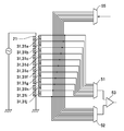
- FIG. 5 is an explanatory diagram schematically showing a circuit for sequentially driving the plurality of detection coils 30 in the magnetic sensor device 10 according to the first embodiment of the present invention.
- the first excitation coil 21 and the second excitation coil 22 are driven alternately at different times. Therefore, the first detection coil 31 detects the AC magnetic field of the first excitation coil 21 without adopting a configuration such as supplying alternating currents having different frequencies to the first excitation coil 21 and the second excitation coil 22. Based on the result and the result of the second detection coil 32 detecting the AC magnetic field of the second excitation coil 22, the presence or absence of the metallic foreign object S can be detected.
- the plurality of detection coils 30 (the plurality of first detection coils 31 and the plurality of second detection coils 32) are sequentially driven.
- the plurality of first detection coils 31 are sequentially driven in the period in which the first excitation coil 21 is driven will be described with reference to FIG.
- the plurality of first detection coils 31 are the first detection coils 31a, 31b, 31c,...
- the ends of the first detection coils 31a, 31b, 31c,... Are connected to analog switches 51, 52 such as an analog multiplexer, and the outputs of the analog switches 51, 52 are connected to an operational amplifier 53 for subtraction.
- analog switches 51, 52 such as an analog multiplexer
- the outputs of the analog switches 51, 52 are connected to an operational amplifier 53 for subtraction.
- the second detection coil 32 is also configured in the same manner as the first detection coil 31, and the outputs of the plurality of second detection coils 32 are output by the analog switches 51 and 52 during the period in which the second excitation coil 22 is driven. Are sequentially input to the operational amplifier 53, and a change in the signal due to the metallic foreign object S is detected.
- the inspection circuit 54 Presence / absence and its position can be detected. According to this configuration, there is an advantage that the inspection circuit 54 can be made common to the plurality of first detection coils 31 and the inspection circuit 54 can be made common to the plurality of second detection coils 32.
- FIG. 6 is an explanatory diagram schematically showing another circuit for sequentially driving the plurality of detection coils 30 in the magnetic sensor device 10 according to the first embodiment of the present invention.
- the first excitation coil 21 and the second excitation coil 22 are driven alternately at different times. Therefore, the first detection coil 31 detects the AC magnetic field of the first excitation coil 21 without adopting a configuration such as supplying alternating currents having different frequencies to the first excitation coil 21 and the second excitation coil 22. Based on the result and the result of the second detection coil 32 detecting the AC magnetic field of the second excitation coil 22, the presence or absence of the metallic foreign object S can be detected.
- the plurality of detection coils 30 are sequentially driven.
- the difference between the signals detected by the adjacent first detection coils 31 is sequentially output from the plurality of first detection coils 31 while shifting the time, and the adjacent second second coils are output from the plurality of second detection coils 32.
- Differences in signals detected by the detection coil 32 are sequentially output at different times.
- first detection coils 31 when the plurality of first detection coils 31 are the first detection coils 31a, 31b, 31c,..., The first detection coils 31a, 31b, 31c,.
- the ends of the first detection coils 31a, 31b, 31c,... Are connected to analog switches 51, 52 such as analog multiplexers, and the outputs of the analog switches 51, 52 are connected to an operational amplifier 53.
- connection point of the adjacent first detection coils 31 is connected to an analog switch 55 such as an analog demultiplexer.
- the analog switch 55 sequentially sets the connection points of the adjacent first detection coils 31 to the ground potential, and the analog switch 51 is interlocked with the operation. , 52, the difference between the signals detected by the adjacent first detection coils 31 is sequentially input to the operational amplifier 53, and a change in the signal due to the metallic foreign object S is detected.
- the analog switch 55 sets the connection point of the first detection coils 31a and 31b to the ground potential
- the analog switches 51 and 52 are opposite to the connection point of the first detection coil 31a with the first detection coil 31b.
- the output signal from the end is input to the operational amplifier 53, and the output signal from the end opposite to the connection point between the first detection coil 31b and the first detection coil 31a is input to the operational amplifier 53.
- the analog switch 55 sets the connection point of the first detection coils 31b and 31c to the ground potential
- the analog switch 51 and 52 are the connection points of the first detection coil 31b and the first detection coil 31c.
- An output signal from the opposite end is input to the operational amplifier 53, and an output signal from the opposite end of the first detection coil 31c to the first detection coil 31b is input to the operational amplifier 53.
- the inspection circuit 54 detects the presence or absence of the metallic foreign object S based on the output from the operational amplifier 53.
- the second detection coil 32 is also configured in the same manner as the first detection coil 31, and the adjacent second detection coils 32 are placed by the analog switches 51, 52, 55 during the period in which the second excitation coil 22 is driven.
- the difference between the signals detected in step S1 is sequentially input to the operational amplifier 53, and the inspection circuit 54 detects the presence or absence of the metal foreign object S based on the output from the operational amplifier 53.
- the inspection circuit 54 can be made common to the plurality of first detection coils 31 and the inspection circuit 54 can be made common to the plurality of second detection coils 32. Further, since the differential between the adjacent detection coils 30 is used, there is an advantage that it is difficult to be influenced by the influence of the environmental temperature and the fluctuation of the drive current.
- the excitation coil 20 and the detection coil 30 are arranged with respect to the sample arrangement space 40, and the detection coil 30 generates an AC magnetic field generated by the excitation coil 20. To detect. For this reason, when the metal foreign matter S is mixed in the sample to be inspected such as the banknote 2, the detection result of the detection coil 30 is changed, so that the presence or absence of the metal foreign matter S can be detected.
- the excitation coil 20 and the detection coil 30 are respectively arranged on opposite sides of the sample arrangement space 40.
- the sample to be inspected when the sample to be inspected is in a position near the excitation coil 20 in the sample arrangement space 40, the sample to be inspected is in a position far from the detection coil 30, and the sample to be inspected is in a position far from the excitation coil 20. In some cases, the sample to be inspected is at a position close to the detection coil 30. Therefore, it is possible to mitigate changes in sensitivity depending on which position in the sample arrangement space 40 the sample to be inspected, so it is possible to mitigate changes in sensitivity due to the position of the sample to be inspected.
- the excitation coil 20 a first excitation coil 21 disposed on one side of the sample arrangement space 40 and a second excitation coil 22 disposed on the other side of the sample arrangement space 40 are provided.
- the detection coil 30 the first detection coil 31 that detects the alternating magnetic field of the first excitation coil 21 on the other side of the sample arrangement space 40 and the alternating magnetic field of the second excitation coil 22 on one side of the sample arrangement space 40 are detected.
- a second detection coil 32 is provided. For this reason, the same sensitivity can be obtained regardless of the distance from the excitation coil 20 or the detection coil 30 in the sample arrangement space 40.
- the first excitation coil 21 is disposed on the opposite side of the sample arrangement space 40 with respect to the second detection coil 32, and the second excitation coil 22 is defined with respect to the sample arrangement space 40 with respect to the first detection coil 31. Located on the opposite side. For this reason, the exciting coil 20 (the first exciting coil 21 and the second exciting coil 22) is located farther from the sample arrangement space 40 than the detecting coil 30 (the first detecting coil 31 and the second detecting coil 32). A magnetic field can be generated over the entire sample arrangement space 40.
- each of the plurality of first detection coils 31 can be magnetically arranged at the same or substantially the same position, and each of the plurality of second detection coils 32 can be arranged magnetically at the same or substantially the same position. be able to. Therefore, it is possible to easily detect whether or not the metal foreign object S exists based on the detection results of the detection coils 30 of the plurality of first detection coils 31 and the plurality of second detection coils 32. .
- the excitation coil 20 (the first excitation coil 21 and the second excitation coil 22) and the detection coil 30 (the first detection coil 31 and the second detection coil 32) are air-core coils.
- the degree of freedom in arranging the excitation coil 20 and the detection coil 30 is high.
- a core made of a magnetic material is arranged inside the exciting coil 20 (the first exciting coil 21 and the second exciting coil 22) or inside the detecting coil 30 (the first detecting coil 31 and the second detecting coil 32). Also good.
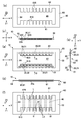
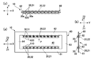
- FIG. 7 is an explanatory diagram of the magnetic sensor device according to the second embodiment of the present invention.
- FIGS. 7 (a), (b), (c), (d), (e), and (f) are magnetic fields. Front view of sensor device, side view of magnetic sensor device, explanatory view of magnetic sensor device viewed from direction of arrow R, explanatory view of magnetic sensor device viewed from direction of arrow Q, front view of core used in magnetic sensor device, It is explanatory drawing which shows typically the magnetic force line which generate
- the magnetic sensor device 10 of this embodiment is also linearly arranged in the X-axis direction, facing the excitation coil 20 in the Z-axis direction, similarly to the first embodiment.
- a sample arrangement space 40 in which a sample to be inspected such as the banknote 2 shown in FIG. 1 is arranged is formed between the detection coil 30 and the excitation coil 20.
- the exciting coil 20 a first exciting coil 21 disposed on one side Z1 in the Z-axis direction with respect to the sample arrangement space 40, and an other side Z2 in the Z-axis direction with respect to the sample arrangement space 40 are disposed.
- a second excitation coil 22 is provided.
- the first detection coil 31 detects the AC magnetic field of the first excitation coil 21, while the second detection coil 32 detects the AC magnetic field of the second excitation coil 22.
- the first excitation coil 21 and the second detection coil 32 are provided on the first core 610 disposed on the one side Z1 in the Z-axis direction with respect to the sample arrangement space 40, and the second The excitation coil 22 and the first detection coil 31 are provided on the second core 620 disposed on the other side Z2 in the Z-axis direction with respect to the sample arrangement space 40, and the first core 610 and the second core 620 are magnetic. Is bound to.
- the excitation coil 20 (the first excitation coil 21 and the second excitation coil 22) and the detection coil 30 (the first detection coil 31 and the second detection coil 32) are Z with respect to the sample arrangement space 40. It is wound around a common core 60 extending from one side Z1 in the axial direction to the other side Z2.
- the core 60 has a plate shape whose thickness direction is directed in the Y-axis direction, and a frame portion 61 extending in the X-axis direction on one side Z1 in the Z-axis direction with respect to the sample arrangement space 40;
- a frame portion 62 that extends in the X-axis direction on the other side Z2 in the Z-axis direction with respect to the sample arrangement space 40, a frame portion 63 that connects one ends of the frame portions 61 and 62 in the X-axis direction, and a frame portion 61 , 62 has a rectangular frame shape provided with a frame portion 64 that connects the other ends in the X-axis direction.
- the core 60 has a rectangular shape with the frame portions 61 and 62 as long sides and the frame portions 63 and 64 as short sides.
- a plurality of salient pole-shaped first cores 610 protruding toward the frame portion 62 are formed on the edge facing the frame portion 62 in the X-axis direction.
- a plurality of salient pole-shaped second cores 620 projecting toward the frame portion 61 are formed in the X-axis direction on the edge facing the 61.
- the first exciting coil 21 is wound around the base portion located on the frame 61 side of the first core 610 through the outside of the first core 610 located at both ends in the X-axis direction.
- the second detection coil 32 is wound around each of the plurality of first cores 610 at the tip portion of the one core 610 located on the sample arrangement space 40 side.
- the second exciting coil 22 is wound around the base portion of the second core 620 that is located on the frame 62 side through the outside of the second core 620 that is located at both ends in the X-axis direction.
- the first detection coil 31 is wound around each of the plurality of second cores 620 at the distal end portion of the two-core 620 located on the sample arrangement space 40 side.
- the first excitation coil 21 is disposed on the opposite side (one side Z1 in the Z-axis direction) from the sample arrangement space 40 with respect to the plurality of second detection coils 32, and the second excitation coil 22 includes a plurality of It arrange
- the detection coil 30 when alternating current is supplied to the excitation coil 20 by a drive circuit (not shown), the detection coil 30 generates a magnetic field generated by the excitation coil 20. Is detected. At that time, the first excitation coil 21 and the second excitation coil 22 are driven with a time shift. The plurality of first detection coils 31 are sequentially driven at different times, and the plurality of second detection coils 32 are sequentially driven at different times.
- the magnetic lines of force L draw a curve in which the direction of the tangent coincides with the direction of the magnetic field by the exciting coil 20.
- a curve is drawn such that the tangential direction of the magnetic lines of force L coincides with the direction of the magnetic field by the exciting coil 20 at a position away from the metal foreign matter S.
- the magnetic lines of force L0 are distorted. Accordingly, the detection result of the detection coil 30 located near the metal foreign object S among the plurality of detection coils 30 changes. Therefore, the same effects as in the first embodiment can be obtained, such as the presence of the metallic foreign object S can be detected.
- the exciting coil 20 and the detection coil 30 are wound around the core 60, the leakage magnetic flux can be reduced. Therefore, according to the present embodiment, high sensitivity can be obtained and the resolution is high because the leakage magnetic flux hardly affects the adjacent detection coils 30.
- the core 60 is not limited to the form shown in FIG. 7, and the first core 610 and the second core 620 are magnetically coupled, and the first excitation coil 21 and the plurality of second detection elements are coupled. It suffices if the sample arrangement space 40 is provided in a space where the coil 32, the second excitation coil 22, and the first detection coil 31 face each other.
- the magnetic body constituting the first core 610 and the magnetic body constituting the second core 620 are arranged close to each other, thereby being magnetically coupled. It may be a configuration.
- FIG. 8 is an explanatory diagram of the magnetic sensor device according to the third embodiment of the present invention.
- FIGS. 8A, 8B, and 8C are a front view of the magnetic sensor device and a side view of the magnetic sensor device.
- FIG. 5 is an explanatory view of the magnetic sensor device viewed from the direction of arrow P. Since the basic configuration of this embodiment is the same as that of Embodiments 1 and 2, common portions are denoted by the same reference numerals and description thereof is omitted.
- the magnetic sensor device 10 of the present embodiment is also linearly arranged in the X-axis direction so as to face the excitation coil 20 in the Z-axis direction as in the first embodiment.
- a sample arrangement space 40 in which a sample to be inspected such as the banknote 2 shown in FIG. 1 is arranged is formed between the detection coil 30 and the excitation coil 20.
- the exciting coil 20 a first exciting coil 21 disposed on one side Z1 in the Z-axis direction with respect to the sample arrangement space 40, and an other side Z2 in the Z-axis direction with respect to the sample arrangement space 40 are disposed.
- a second excitation coil 22 is provided.
- the first detection coil 31 detects the AC magnetic field of the first excitation coil 21, while the second detection coil 32 detects the AC magnetic field of the second excitation coil 22.
- the excitation coil 20 (the first excitation coil 21 and the second excitation coil 22) and the detection coil 30 (the first detection coil 31 and the second detection coil 32) as in the second embodiment.
- the core 60 also has a plurality of salient pole-shaped first cores 610 projecting toward the frame portion 62 in the frame portion 61 at the edge facing the frame portion 62 in the X-axis direction.
- a plurality of salient pole-like second cores 620 that protrude toward the frame portion 61 are formed in the X-axis direction on the edge facing the frame portion 61.
- the first core 610 is wound with the second detection coil 32 for each of the plurality of first cores 610, and the first detection cores 610 are positioned at both ends in the X-axis direction so as to cover the second detection coil 32.
- the first exciting coil 21 is wound through the outside of the one core 610.
- the second core 620 is wound with the first detection coil 31 for each of the plurality of second cores 620, and the second core located at both ends in the X-axis direction so as to cover the first detection coil 31.
- a second exciting coil 22 is wound through the outside of 620. That is, the first excitation coil 21 is wound around the second detection coil 32, and the second excitation coil 22 is wound around the first detection coil 31.
- the exciting coil 20 and the detection coil 30 are wound around the common core 60 as in the second embodiment, the leakage magnetic flux can be reduced. Therefore, according to the present embodiment, high sensitivity can be obtained and the resolution is high because the leakage magnetic flux hardly affects the adjacent detection coils 30.
- the magnetic body constituting the first core 610 and the magnetic body constituting the second core 620 are arranged close to each other so that they are magnetically coupled. Also good.
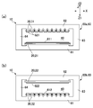
- FIG. 9 is a front view of a magnetic sensor device according to Embodiment 4 of the present invention. Since the basic configuration of this embodiment is the same as that of Embodiments 1 and 2, common portions are denoted by the same reference numerals and description thereof is omitted.
- the magnetic sensor device 10 of this embodiment is also linearly arranged in the X-axis direction so as to face the excitation coil 20 in the Z-axis direction as in the first embodiment.
- a sample arrangement space 40 in which a sample to be inspected such as the banknote 2 shown in FIG. 1 is arranged is formed between the detection coil 30 and the excitation coil 20. .
- the excitation coil 20 is arranged only on one side Z1 in the Z-axis direction with respect to the sample arrangement space 40, and the plurality of detection coils 30 are arranged on the other side Z2 in the Z-axis direction with respect to the sample arrangement space 40. It is provided only at a position facing the exciting coil 20 with the arrangement space 40 in between.
- the detection coil 30 detects the AC magnetic field of the excitation coil 20.
- the excitation coil 20 and the detection coil 30 are wound around the core as in the second and third embodiments. More specifically, the excitation coil 20 is provided on the excitation coil core 615 disposed on one side Z1 in the Z-axis direction with respect to the sample arrangement space 40, and the detection coil 30 is provided with respect to the sample arrangement space 40. Provided in the detection coil core 625 disposed on the other side Z2 in the Z-axis direction, the excitation coil core 615 and the detection coil core 625 are magnetically coupled. More specifically, the excitation coil 20 and the detection coil 30 are wound around a common core 60 extending from one side Z1 in the Z-axis direction to the other side Z2 with respect to the sample arrangement space 40.
- one salient pole-shaped exciting coil core 615 that projects toward the frame portion 62 extends in the X-axis direction at the edge of the frame portion 61 that faces the frame portion 62.
- the exciting coil 20 is wound around the exciting coil core 615.
- a plurality of salient pole-shaped detection coil cores 625 projecting toward the frame portion 61 are formed on the edge facing the frame portion 61 in the X-axis direction.
- a detection coil 30 is wound around each core 625.
- the exciting coil 20 and the detection coil 30 are wound around the core 60 as in the second and third embodiments, the leakage magnetic flux can be reduced. Therefore, according to the present embodiment, high sensitivity can be obtained and the resolution is high because the leakage magnetic flux hardly affects the adjacent detection coils 30.
- the magnetic body constituting the exciting coil core 615 and the magnetic body constituting the detection coil core 625 are arranged close to each other so as to be magnetically coupled. May be.
- FIG. 10 is an explanatory diagram of the magnetic sensor device according to the fifth embodiment of the present invention
- FIGS. 10A and 10B are explanatory diagrams of the magnetic sensor device. It is a front view of the core 60a around which the detection coil 32 is wound, and a front view of the core 60b around which the second excitation coil 22 and the first detection coil 31 are wound. Since the basic configuration of this embodiment is the same as that of Embodiments 1, 2, 4, etc., common portions are denoted by the same reference numerals and description thereof is omitted.
- the first excitation coil 21 and the second detection are arranged on one side Z1 in the Z-axis direction with respect to the sample arrangement space 40 using the configuration of the magnetic sensor device 10 shown in FIG.
- the coil 32 is disposed, and the second excitation coil 22 and the first detection coil 31 are disposed on the other side Z2 in the Z-axis direction. That is, the core 60 shown in FIG. 9 and the core 60 obtained by inverting the core 60 shown in FIG. 9 in the Z-axis direction are alternately arranged in the Y-axis direction as cores 60a and 60b, respectively.
- a salient pole-shaped first exciting coil core 611 protruding toward the frame portion 62 is formed on the edge of the frame portion 61 facing the frame portion 62.
- the first exciting coil 21 is wound around the first exciting coil core 611.
- a plurality of salient pole-shaped first detection coil cores 621 projecting toward the frame portion 61 are formed in the X-axis direction on the edge facing the frame portion 61.
- the first detection coil 31 is wound around the core 621.
- the core 60b shown in FIG. 10B is disposed to face the core 60a in the Y-axis direction.
- a salient pole-shaped second exciting coil core 622 that protrudes toward the frame portion 61 is formed at the edge of the frame portion 62 that faces the frame portion 61, and the second exciting coil core is formed.
- a second exciting coil 22 is wound around 622.
- a plurality of salient pole-shaped second detection coil cores 612 projecting toward the frame portion 62 are formed in the X axis direction on the edge facing the frame portion 62.
- the second detection coil 32 is wound around the core 612.
- the magnetic body constituting the first exciting coil core 611 and the magnetic body constituting the first detection coil core 621 are arranged close to each other, thereby being magnetically coupled.
- a configuration in which the magnetic body constituting the second exciting coil core 622 and the magnetic body constituting the second detection coil core 612 are arranged close to each other to be magnetically coupled may be employed. .
- a plurality of first detection coils 31 and a plurality of second detection coils 32 are provided, but a configuration in which one each of the first detection coil 31 and the second detection coil 32 is provided may be adopted.
- the detection of the metallic foreign matter S is excited.
- the present invention may be applied to the magnetic sensor device 10 for detecting a metallic material such as magnetic ink added to the specimen to be inspected.
- the metal material such as the metallic foreign object S may be detected based on the signals detected by the first detection coil 31 and the second detection coil 32, but the first is disposed at a position facing each other in the Z-axis direction.
- a metal material such as the metallic foreign object S may be detected based on the sum of the detection results of the first detection coil 31 and the second detection coil 32.
Landscapes
- Physics & Mathematics (AREA)
- Life Sciences & Earth Sciences (AREA)
- Engineering & Computer Science (AREA)
- Remote Sensing (AREA)
- General Physics & Mathematics (AREA)
- Electromagnetism (AREA)
- Environmental & Geological Engineering (AREA)
- Geology (AREA)
- General Life Sciences & Earth Sciences (AREA)
- Geophysics (AREA)
- Chemical & Material Sciences (AREA)
- Chemical Kinetics & Catalysis (AREA)
- Electrochemistry (AREA)
- Health & Medical Sciences (AREA)
- Analytical Chemistry (AREA)
- Biochemistry (AREA)
- General Health & Medical Sciences (AREA)
- Immunology (AREA)
- Pathology (AREA)
- Investigating Or Analyzing Materials By The Use Of Magnetic Means (AREA)
- Geophysics And Detection Of Objects (AREA)
Description
2 紙幣(検査対象試料)
10 磁気センサ装置
13、14 ベルト式搬送機構(搬送機構)
20 励磁コイル
21 第1励磁コイル
22 第2励磁コイル
30 検出コイル
31 第1検出コイル
32 第2検出コイル
40 試料配置空間
60、60a、60b コア
610 第1コア
611 第1励磁コイル用コア
612 第2検出コイル用コア
615 励磁コイル用コア
620 第2コア
621 第1検出コイル用コア
622 第2励磁コイル用コア
625 検出コイル用コア
(検査装置の全体構成)
図1は、本発明の実施の形態1に係る磁気センサ装置を備えた検査機器の説明図である。図2は、本発明の実施の形態1に係る磁気センサ装置の説明図であり、図2(a)、(b)、(c)、(d)は、磁気センサ装置の正面図、側面図、励磁コイルの説明図、および検出コイルの説明図である。
図3は、本発明の実施の形態1に係る磁気センサにおける測定原理を示す説明図であり、図3(a)、(b)は、金属異物が存在しない状態の説明図、および金属異物が存在する状態の説明図である。図4は、本発明の実施の形態1に係る磁気センサの感度の説明図であり、図4(a)、(b)、(c)、(d)は、試料配置空間における検査対象試料の位置を示す説明図、検査対象試料の位置と検出コイルでの検出量の変化量を模式的に示す説明図、検査対象試料の位置と励磁コイルが発生させた磁界強度との関係を模式的に示す説明図、および検査対象試料の位置と検出コイルでの検出強度との関係を模式的に示す説明図である。
Pa>Pb>Pc
にある。また、図4(c)に点線L22で示すように、第2検出コイル32も、第1検出コイル31と同様、金属異物Sとの距離が近い位置にある場合、高い感度を有し、金属異物Sとの距離が長くなるに伴って感度が低下する傾向にある。このため、磁界が一定であれば、金属異物Sが位置Pa、Pb、Pcにあった場合における第2検出コイル32の感度は、以下の関係
Pa<Pb<Pc
にある。
Pa<Pb<Pc
にある。それ故、本形態の磁気センサ装置10において、金属異物Sが位置Pa、Pb、Pcにある場合における第1検出コイル31の出力変化は、図4(c)、(d)に示す関係が合成される結果、図4(b)に実線L11で示すように、位置Pa、Pb、Pcの何れの位置に金属異物Sが存在している場合でも十分に高いレベルである。それ故、第1検出コイル31は適正な感度を有している。
Pa>Pb>Pc
にある。それ故、本形態の磁気センサ装置10において、金属異物Sが位置Pa、Pb、Pcにある場合における第2検出コイル32の出力変化は、図4(c)、(d)に示す関係が合成される結果、図4(b)に点線L12で示すように、位置Pa、Pb、Pcの何れの位置に金属異物Sが存在している場合でも十分に高いレベルである。それ故、第2検出コイル32は適正な感度を有している。
Pa>Pb>Pc
にある。これに対して、図4(b)に点線L12で示すように、第2検出コイル32の出力変化は、位置Pa、Pb、Pcの何れの位置に金属異物Sが存在している場合でも十分に高いレベルであるが、それでも、第2検出コイル32は、金属異物Sとの距離が近い位置にある場合、第2検出コイル32の出力変化が大きく、金属異物Sとの距離が長くなるに伴って第2検出コイル32の出力変化が小さくなる傾向にある。このため、金属異物Sが位置Pa、Pb、Pcにあった場合における第2検出コイル32の出力変化は、以下の関係
Pa<Pb<Pc
にある。
図5は、本発明の実施の形態1に係る磁気センサ装置10において複数の検出コイル30を順次駆動するための回路を模式的に示す説明図である。
図6は、本発明の実施の形態1に係る磁気センサ装置10において複数の検出コイル30を順次駆動するための別の回路を模式的に示す説明図である。
以上説明したように、本形態の磁気センサ装置10では、試料配置空間40に対して励磁コイル20および検出コイル30が配置されており、検出コイル30は、励磁コイル20が発生させた交流磁界を検出する。このため、紙幣2等の検査対象試料に金属異物Sが混在している場合には、検出コイル30での検出結果が変化するので、金属異物Sの有無を検出することができる。ここで、励磁コイル20と検出コイル30とは、試料配置空間40を挟んだ反対側に各々、配置されている。従って、試料配置空間40のうち、励磁コイル20に近い位置に検査対象試料がある場合には、検査対象試料は検出コイル30から遠い位置にあり、励磁コイル20から遠い位置に検査対象試料がある場合には、検査対象試料は検出コイル30に近い位置にある。それ故、試料配置空間40のいずれの位置に検査対象試料があるかによって感度が変化することを緩和することができるので、検査対象試料の位置に起因する感度の変化を緩和することができる。
図7は、本発明の実施の形態2に係る磁気センサ装置の説明図であり、図7(a)、(b)、(c)、(d)、(e)、(f)は、磁気センサ装置の正面図、磁気センサ装置の側面図、磁気センサ装置を矢印Rの方向からみた説明図、磁気センサ装置を矢印Qの方向からみた説明図、磁気センサ装置に用いたコアの正面図、および磁気センサ装置で発生する磁力線を模式的に示す説明図である。なお、本形態の基本的な構成は実施の形態1と同様であるため、共通する部分には同一の符号を付して図示し、それらの説明を省略する。
図8は、本発明の実施の形態3に係る磁気センサ装置の説明図であり、図8(a)、(b)、(c)は、磁気センサ装置の正面図、磁気センサ装置の側面図、および磁気センサ装置を矢印Pの方向からみた説明図である。なお、本形態の基本的な構成は実施の形態1、2と同様であるため、共通する部分には同一の符号を付して図示し、それらの説明を省略する。
図9は、本発明の実施の形態4に係る磁気センサ装置の正面図である。なお、本形態の基本的な構成は実施の形態1、2と同様であるため、共通する部分には同一の符号を付して図示し、それらの説明を省略する。
図10は、本発明の実施の形態5に係る磁気センサ装置の説明図であり、図10(a)、(b)は、磁気センサ装置の説明図であり、第1励磁コイル21および第2検出コイル32を巻回したコア60aの正面図、および第2励磁コイル22および第1検出コイル31を巻回したコア60bの正面図である。なお、本形態の基本的な構成は実施の形態1、2、4等と同様であるため、共通する部分には同一の符号を付して図示し、それらの説明を省略する。
上記実施の形態では、第1検出コイル31および第2検出コイル32を各々、複数設けたが、第1検出コイル31および第2検出コイル32を各々、1つずつ設けた構成を採用してもよい。また、上記実施の形態では、金属異物Sの検出を励磁したが、検査対象試料に付加されている磁気インク等の金属材料を検出するための磁気センサ装置10に本発明を適用してもよい。また、第1検出コイル31および第2検出コイル32で検出された各信号に基づいて金属異物S等の金属材料を検出してもよいが、Z軸方向で相対向する位置に配置された第1検出コイル31および第2検出コイル32の各検出結果の和に基づいて金属異物S等の金属材料を検出してもよい。
Claims (13)
- 励磁コイルと、
該励磁コイルに対向し、前記励磁コイルが発生させる交流磁界を検出する検出コイルと、
該検出コイルと前記励磁コイルとの間で検査対象試料が配置される試料配置空間と、
を有していることを特徴とする磁気センサ装置。 - 前記励磁コイルとして、前記試料配置空間の一方側に配置された第1励磁コイルと、前記試料配置空間の他方側に配置された第2励磁コイルとが設けられ、
前記検出コイルとして、前記試料配置空間の前記他方側で前記第1励磁コイルの交流磁界を検出する第1検出コイルと、前記試料配置空間の前記一方側で前記第2励磁コイルの交流磁界を検出する第2検出コイルとが設けられていることを特徴とする請求項1に記載の磁気センサ装置。 - 前記第1励磁コイルと前記第2励磁コイルとは、時間をずらして駆動されることを特徴とする請求項2に記載の磁気センサ装置。
- 前記励磁コイルは、前記試料配置空間の一方側に配置された励磁コイル用コアに設けられ、
前記検出コイルは、前記試料配置空間の他方側に配置された検出コイル用コアに設けられ、
前記励磁コイル用コアと前記検出コイル用コアとは磁気的に結合していることを特徴とする請求項1に記載の磁気センサ装置。 - 前記第1励磁コイルおよび前記第2検出コイルは、前記試料配置空間の前記一方側に配置された第1コアに設けられ、
前記第2励磁コイルおよび前記第1検出コイルは、前記試料配置空間の前記他方側に配置された第2コアに設けられ、
前記第1コアと前記第2コアとは磁気的に結合していることを特徴とする請求項2または3に記載の磁気センサ装置。 - 前記第1励磁コイルは、前記試料配置空間の前記一方側に配置された第1励磁コイル用コアに設けられ、
前記第1検出コイルは、前記試料配置空間の前記他方側に配置された第1検出コイル用コアに設けられ、
前記第1励磁コイル用コアと前記第1検出コイル用コアとは磁気的に結合しており、
前記第2励磁コイルは、前記試料配置空間の前記他方側に配置された第2励磁コイル用コアに設けられ、
前記第2検出コイルは、前記試料配置空間の前記一方側に配置された第2検出コイル用コアに設けられ、
前記第2励磁コイル用コアと前記第2検出コイル用コアとは磁気的に結合していることを特徴とする請求項2または3に記載の磁気センサ装置。 - 前記励磁コイルおよび前記検出コイルはいずれも、空芯コイルであることを特徴とする請求項1乃至3の何れか一項に記載の磁気センサ装置。
- 前記第1励磁コイル、前記第1検出コイル、前記第2励磁コイルおよび前記第2検出コイルはいずれも、空芯コイルであって、
前記第1励磁コイルは、前記第2検出コイルに対して前記試料配置空間とは反対側に配置され、
前記第2励磁コイルは、前記第1検出コイルに対して前記試料配置空間とは反対側に配置されていることを特徴とする請求項1乃至3の何れか一項に記載の磁気センサ装置。 - 前記第1検出コイルは、前記試料配置空間の前記他方側に複数配置され、
前記第2検出コイルは、前記試料配置空間の前記一方側に複数配置されていることを特徴とする請求項2、3、5、6または8に記載の磁気センサ装置。 - 前記複数の第1検出コイルは、前記試料配置空間に沿って直線的に配置され、
前記複数の第2検出コイルは、前記試料配置空間に沿って直線的に配置されていることを特徴とする請求項9に記載の磁気センサ装置。 - 前記複数の第1検出コイルは、時間をずらして順次駆動され、
前記複数の第2検出コイルは、時間をずらして順次駆動されることを特徴とする請求項9または10に記載の磁気センサ装置。 - 前記複数の第1検出コイルからは、隣り合う第1検出コイルで検出される信号の差が出力され、
前記複数の第2検出コイルからは、隣り合う第2検出コイルで検出される信号の差が出力されることを特徴とする請求項9乃至11の何れか一項に記載の磁気センサ装置。 - 前記試料配置空間に前記検査対象試料を搬送する搬送機構を有していることを特徴とする請求項1乃至12の何れか一項に記載の磁気センサ装置。
Priority Applications (2)
| Application Number | Priority Date | Filing Date | Title |
|---|---|---|---|
| KR1020157000196A KR20150016996A (ko) | 2012-07-26 | 2013-06-13 | 자기 센서 장치 |
| US14/414,319 US20150198561A1 (en) | 2012-07-26 | 2013-06-13 | Magnetic sensor device |
Applications Claiming Priority (2)
| Application Number | Priority Date | Filing Date | Title |
|---|---|---|---|
| JP2012-165314 | 2012-07-26 | ||
| JP2012165314A JP2014025771A (ja) | 2012-07-26 | 2012-07-26 | 磁気センサ装置 |
Publications (1)
| Publication Number | Publication Date |
|---|---|
| WO2014017207A1 true WO2014017207A1 (ja) | 2014-01-30 |
Family
ID=49997023
Family Applications (1)
| Application Number | Title | Priority Date | Filing Date |
|---|---|---|---|
| PCT/JP2013/066291 Ceased WO2014017207A1 (ja) | 2012-07-26 | 2013-06-13 | 磁気センサ装置 |
Country Status (4)
| Country | Link |
|---|---|
| US (1) | US20150198561A1 (ja) |
| JP (1) | JP2014025771A (ja) |
| KR (1) | KR20150016996A (ja) |
| WO (1) | WO2014017207A1 (ja) |
Families Citing this family (7)
| Publication number | Priority date | Publication date | Assignee | Title |
|---|---|---|---|---|
| WO2015129229A1 (ja) * | 2014-02-26 | 2015-09-03 | パナソニックIpマネジメント株式会社 | 位置検出装置 |
| JP6326660B2 (ja) * | 2014-11-12 | 2018-05-23 | 住友電工焼結合金株式会社 | 焼結体の非破壊検査方法 |
| KR101670427B1 (ko) * | 2016-06-10 | 2016-10-28 | 노바센(주) | 외란에 강인한 고감도 금속검출기 |
| JP6881348B2 (ja) * | 2018-02-26 | 2021-06-02 | Jfeスチール株式会社 | 鋼板の磁気変態率測定装置 |
| JP7231357B2 (ja) * | 2018-08-30 | 2023-03-01 | 矢崎エナジーシステム株式会社 | 導体劣化検出装置 |
| JP2020173631A (ja) | 2019-04-11 | 2020-10-22 | グローリー株式会社 | 紙葉類処理装置および異物混入判定方法 |
| JP7343390B2 (ja) * | 2019-12-27 | 2023-09-12 | ローム株式会社 | 異物検出装置 |
Citations (5)
| Publication number | Priority date | Publication date | Assignee | Title |
|---|---|---|---|---|
| JPH02304348A (ja) * | 1989-05-18 | 1990-12-18 | Nippon Keisoku Kogyo Kk | 交流磁界による物品の検査装置 |
| JP2005017118A (ja) * | 2003-06-26 | 2005-01-20 | Kawashima Seisakusho:Kk | 金属探知機及びペーパー状物品の検査装置 |
| JP2006113043A (ja) * | 2004-09-14 | 2006-04-27 | Hashima:Kk | 検針装置 |
| JP2008134703A (ja) * | 2006-11-27 | 2008-06-12 | Fuji Xerox Co Ltd | 物体検知装置及びその検知方法 |
| JP2012122955A (ja) * | 2010-12-10 | 2012-06-28 | Fuji Xerox Co Ltd | 検知装置およびプログラム |
Family Cites Families (3)
| Publication number | Priority date | Publication date | Assignee | Title |
|---|---|---|---|---|
| JP5262436B2 (ja) * | 2008-08-27 | 2013-08-14 | Jfeスチール株式会社 | 磁気測定方法および装置 |
| JP5423023B2 (ja) * | 2009-02-06 | 2014-02-19 | 富士ゼロックス株式会社 | 物体検知装置 |
| US8952708B2 (en) * | 2011-12-02 | 2015-02-10 | Neovision Llc | Impedance resonance sensor for real time monitoring of different processes and methods of using same |
-
2012
- 2012-07-26 JP JP2012165314A patent/JP2014025771A/ja active Pending
-
2013
- 2013-06-13 WO PCT/JP2013/066291 patent/WO2014017207A1/ja not_active Ceased
- 2013-06-13 KR KR1020157000196A patent/KR20150016996A/ko not_active Ceased
- 2013-06-13 US US14/414,319 patent/US20150198561A1/en not_active Abandoned
Patent Citations (5)
| Publication number | Priority date | Publication date | Assignee | Title |
|---|---|---|---|---|
| JPH02304348A (ja) * | 1989-05-18 | 1990-12-18 | Nippon Keisoku Kogyo Kk | 交流磁界による物品の検査装置 |
| JP2005017118A (ja) * | 2003-06-26 | 2005-01-20 | Kawashima Seisakusho:Kk | 金属探知機及びペーパー状物品の検査装置 |
| JP2006113043A (ja) * | 2004-09-14 | 2006-04-27 | Hashima:Kk | 検針装置 |
| JP2008134703A (ja) * | 2006-11-27 | 2008-06-12 | Fuji Xerox Co Ltd | 物体検知装置及びその検知方法 |
| JP2012122955A (ja) * | 2010-12-10 | 2012-06-28 | Fuji Xerox Co Ltd | 検知装置およびプログラム |
Also Published As
| Publication number | Publication date |
|---|---|
| US20150198561A1 (en) | 2015-07-16 |
| KR20150016996A (ko) | 2015-02-13 |
| JP2014025771A (ja) | 2014-02-06 |
Similar Documents
| Publication | Publication Date | Title |
|---|---|---|
| WO2014017207A1 (ja) | 磁気センサ装置 | |
| KR101413952B1 (ko) | 자기 패턴 검출 장치 | |
| EP3032252B1 (en) | Magnetic detection device and paper sheet processing device | |
| KR101551514B1 (ko) | 자기 센서 장치 | |
| KR20140051385A (ko) | 측정 장치의 주위 환경들의 자기 특성들을 측정하기 위한 측정 장치 | |
| KR20150090088A (ko) | 자기 센서 장치 | |
| WO2013146755A1 (ja) | 紙葉類磁性評価装置及び紙葉類磁性評価方法 | |
| US7055738B2 (en) | Device for accepting banknotes | |
| JP4003975B2 (ja) | 金属検査方法および金属検査装置 | |
| RU2442151C2 (ru) | Способ выявления подповерхностных дефектов в ферромагнитных объектах | |
| JP2011196773A (ja) | 金属検出装置 | |
| JP2014010118A (ja) | 磁気センサ装置 | |
| JP6103848B2 (ja) | 異物検出装置 | |
| WO2014155866A1 (ja) | 異物検出装置および異物検出方法 | |
| JP2014190886A (ja) | 異物検出装置および異物検出方法 | |
| CN101009027A (zh) | 测量有价证券中磁性材料的传感器及检测装置 | |
| JP2006010665A (ja) | 深い渦電流の浸透を実現する渦電流探傷法および渦電流探傷プローブ | |
| JP2005234626A (ja) | 紙葉類識別センサ及び紙葉類識別装置 | |
| JP2013190939A (ja) | 磁気検出装置、及び紙葉類処理装置 | |
| JPWO2006129716A1 (ja) | 磁気量検出センサ、磁気量検出センサ装置、および紙葉類識別装置 | |
| JP2006053053A (ja) | 渦流探傷用プローブ装置 | |
| CN112740025A (zh) | 利用涡电流的材质异常部检知方法以及材质异常部检知装置 |
Legal Events
| Date | Code | Title | Description |
|---|---|---|---|
| 121 | Ep: the epo has been informed by wipo that ep was designated in this application |
Ref document number: 13823815 Country of ref document: EP Kind code of ref document: A1 |
|
| ENP | Entry into the national phase |
Ref document number: 20157000196 Country of ref document: KR Kind code of ref document: A |
|
| WWE | Wipo information: entry into national phase |
Ref document number: 14414319 Country of ref document: US |
|
| NENP | Non-entry into the national phase |
Ref country code: DE |
|
| 122 | Ep: pct application non-entry in european phase |
Ref document number: 13823815 Country of ref document: EP Kind code of ref document: A1 |