WO2014017102A1 - Procédé d'émission, procédé de réception, émetteur, et récepteur - Google Patents
Procédé d'émission, procédé de réception, émetteur, et récepteur Download PDFInfo
- Publication number
- WO2014017102A1 WO2014017102A1 PCT/JP2013/004551 JP2013004551W WO2014017102A1 WO 2014017102 A1 WO2014017102 A1 WO 2014017102A1 JP 2013004551 W JP2013004551 W JP 2013004551W WO 2014017102 A1 WO2014017102 A1 WO 2014017102A1
- Authority
- WO
- WIPO (PCT)
- Prior art keywords
- bits
- constellation
- real
- symbols
- permutation
- Prior art date
Links
Images


Classifications
-
- H—ELECTRICITY
- H03—ELECTRONIC CIRCUITRY
- H03M—CODING; DECODING; CODE CONVERSION IN GENERAL
- H03M13/00—Coding, decoding or code conversion, for error detection or error correction; Coding theory basic assumptions; Coding bounds; Error probability evaluation methods; Channel models; Simulation or testing of codes
- H03M13/03—Error detection or forward error correction by redundancy in data representation, i.e. code words containing more digits than the source words
- H03M13/05—Error detection or forward error correction by redundancy in data representation, i.e. code words containing more digits than the source words using block codes, i.e. a predetermined number of check bits joined to a predetermined number of information bits
- H03M13/11—Error detection or forward error correction by redundancy in data representation, i.e. code words containing more digits than the source words using block codes, i.e. a predetermined number of check bits joined to a predetermined number of information bits using multiple parity bits
- H03M13/1102—Codes on graphs and decoding on graphs, e.g. low-density parity check [LDPC] codes
- H03M13/1148—Structural properties of the code parity-check or generator matrix
- H03M13/116—Quasi-cyclic LDPC [QC-LDPC] codes, i.e. the parity-check matrix being composed of permutation or circulant sub-matrices
-
- H—ELECTRICITY
- H04—ELECTRIC COMMUNICATION TECHNIQUE
- H04L—TRANSMISSION OF DIGITAL INFORMATION, e.g. TELEGRAPHIC COMMUNICATION
- H04L1/00—Arrangements for detecting or preventing errors in the information received
- H04L1/004—Arrangements for detecting or preventing errors in the information received by using forward error control
- H04L1/0041—Arrangements at the transmitter end
-
- H—ELECTRICITY
- H03—ELECTRONIC CIRCUITRY
- H03M—CODING; DECODING; CODE CONVERSION IN GENERAL
- H03M13/00—Coding, decoding or code conversion, for error detection or error correction; Coding theory basic assumptions; Coding bounds; Error probability evaluation methods; Channel models; Simulation or testing of codes
- H03M13/03—Error detection or forward error correction by redundancy in data representation, i.e. code words containing more digits than the source words
- H03M13/05—Error detection or forward error correction by redundancy in data representation, i.e. code words containing more digits than the source words using block codes, i.e. a predetermined number of check bits joined to a predetermined number of information bits
- H03M13/11—Error detection or forward error correction by redundancy in data representation, i.e. code words containing more digits than the source words using block codes, i.e. a predetermined number of check bits joined to a predetermined number of information bits using multiple parity bits
- H03M13/1102—Codes on graphs and decoding on graphs, e.g. low-density parity check [LDPC] codes
- H03M13/1148—Structural properties of the code parity-check or generator matrix
- H03M13/116—Quasi-cyclic LDPC [QC-LDPC] codes, i.e. the parity-check matrix being composed of permutation or circulant sub-matrices
- H03M13/1165—QC-LDPC codes as defined for the digital video broadcasting [DVB] specifications, e.g. DVB-Satellite [DVB-S2]
-
- H—ELECTRICITY
- H03—ELECTRONIC CIRCUITRY
- H03M—CODING; DECODING; CODE CONVERSION IN GENERAL
- H03M13/00—Coding, decoding or code conversion, for error detection or error correction; Coding theory basic assumptions; Coding bounds; Error probability evaluation methods; Channel models; Simulation or testing of codes
- H03M13/03—Error detection or forward error correction by redundancy in data representation, i.e. code words containing more digits than the source words
- H03M13/05—Error detection or forward error correction by redundancy in data representation, i.e. code words containing more digits than the source words using block codes, i.e. a predetermined number of check bits joined to a predetermined number of information bits
- H03M13/11—Error detection or forward error correction by redundancy in data representation, i.e. code words containing more digits than the source words using block codes, i.e. a predetermined number of check bits joined to a predetermined number of information bits using multiple parity bits
- H03M13/1102—Codes on graphs and decoding on graphs, e.g. low-density parity check [LDPC] codes
- H03M13/1148—Structural properties of the code parity-check or generator matrix
- H03M13/118—Parity check matrix structured for simplifying encoding, e.g. by having a triangular or an approximate triangular structure
- H03M13/1185—Parity check matrix structured for simplifying encoding, e.g. by having a triangular or an approximate triangular structure wherein the parity-check matrix comprises a part with a double-diagonal
-
- H—ELECTRICITY
- H03—ELECTRONIC CIRCUITRY
- H03M—CODING; DECODING; CODE CONVERSION IN GENERAL
- H03M13/00—Coding, decoding or code conversion, for error detection or error correction; Coding theory basic assumptions; Coding bounds; Error probability evaluation methods; Channel models; Simulation or testing of codes
- H03M13/03—Error detection or forward error correction by redundancy in data representation, i.e. code words containing more digits than the source words
- H03M13/05—Error detection or forward error correction by redundancy in data representation, i.e. code words containing more digits than the source words using block codes, i.e. a predetermined number of check bits joined to a predetermined number of information bits
- H03M13/13—Linear codes
- H03M13/19—Single error correction without using particular properties of the cyclic codes, e.g. Hamming codes, extended or generalised Hamming codes
-
- H—ELECTRICITY
- H03—ELECTRONIC CIRCUITRY
- H03M—CODING; DECODING; CODE CONVERSION IN GENERAL
- H03M13/00—Coding, decoding or code conversion, for error detection or error correction; Coding theory basic assumptions; Coding bounds; Error probability evaluation methods; Channel models; Simulation or testing of codes
- H03M13/25—Error detection or forward error correction by signal space coding, i.e. adding redundancy in the signal constellation, e.g. Trellis Coded Modulation [TCM]
- H03M13/255—Error detection or forward error correction by signal space coding, i.e. adding redundancy in the signal constellation, e.g. Trellis Coded Modulation [TCM] with Low Density Parity Check [LDPC] codes
-
- H—ELECTRICITY
- H03—ELECTRONIC CIRCUITRY
- H03M—CODING; DECODING; CODE CONVERSION IN GENERAL
- H03M13/00—Coding, decoding or code conversion, for error detection or error correction; Coding theory basic assumptions; Coding bounds; Error probability evaluation methods; Channel models; Simulation or testing of codes
- H03M13/27—Coding, decoding or code conversion, for error detection or error correction; Coding theory basic assumptions; Coding bounds; Error probability evaluation methods; Channel models; Simulation or testing of codes using interleaving techniques
- H03M13/2703—Coding, decoding or code conversion, for error detection or error correction; Coding theory basic assumptions; Coding bounds; Error probability evaluation methods; Channel models; Simulation or testing of codes using interleaving techniques the interleaver involving at least two directions
- H03M13/2707—Simple row-column interleaver, i.e. pure block interleaving
-
- H—ELECTRICITY
- H03—ELECTRONIC CIRCUITRY
- H03M—CODING; DECODING; CODE CONVERSION IN GENERAL
- H03M13/00—Coding, decoding or code conversion, for error detection or error correction; Coding theory basic assumptions; Coding bounds; Error probability evaluation methods; Channel models; Simulation or testing of codes
- H03M13/65—Purpose and implementation aspects
- H03M13/6522—Intended application, e.g. transmission or communication standard
- H03M13/6552—DVB-T2
Definitions
- the present invention relates to the field of digital communication, and more particularly to a communication system using a rotational constellation with a quasi-cyclic (QC) low-density parity-check (QC LDPC) code.
- QC quasi-cyclic
- QC LDPC quasi-cyclic low-density parity-check
- transmitters for example, interleave codeword bits and map them to real-valued symbols, and multiply D-dimensional vectors by D-row D-column orthogonal matrices for every D real-valued symbols.
- transmitters for example, interleave codeword bits and map them to real-valued symbols, and multiply D-dimensional vectors by D-row D-column orthogonal matrices for every D real-valued symbols.
- the present invention provides a transmission method including interleaving of new codeword bits that can avoid the complexity of the structure of the receiver due to the use of a plurality of dimensions D by the receiver.
- the purpose is to do.
- the orthogonal matrix is a matrix in which the values of the elements of each dimension of the D-dimensional vector are distributed in at least two dimensions, and each constellation block has the same B ⁇ D pseudo values. Formed from the D-dimensional vector made from cyclic blocks, 2 ⁇ D transformed real-valued symbols of each constellation block are mapped to D complex symbols, and D transformed real-valued symbols of the D-dimensional rotation constellation are mapped to D different complex symbols As shown, each step of mapping N ⁇ Q / B converted real-valued symbols to N ⁇ Q / (2 ⁇ B) complex symbols is included.
- Block diagram of a typical transmitter using a rotating constellation with a quasi-cyclic low density parity check code The figure which shows an example of the parity check matrix of a pseudo cyclic low density parity check code
- the figure which shows an example of the bit interleaver for pseudo cyclic low density parity check codes The figure which shows an example of the section permutation of FIG. (A) shows an example of a process of writing an LDPC codeword into a multi-bit section permutation matrix, and (b) shows an example of a process of reading an LDPC codeword from a section permutation matrix.
- (A) shows an example of a process of writing an LDPC codeword to a multi-bit section permutation matrix
- (b) shows an example of a process of reading an LDPC codeword from a multi-bit section permutation matrix
- (C) shows an example of mapping of an LDPC block to a 4-bit 16-QAM constellation
- (d) shows an example of the output of a QAM mapper
- (e) shows an adjacent pair of 4-dimensional rotation constellations.
- the figure which shows an example of the mapping to four complex symbols (cell)
- FIG. 20 shows details of QAM mapping (step 2) and (step 4) in FIG. 20, and (b) shows details of constellation rotation (step 3) and (step 4) in FIG.
- the figure which shows an example of the mapping to the non-rotation constellation of the PAM symbol Block diagram of a receiver using non-iterative decoding in one embodiment of the invention
- Block diagram of a receiver using iterative decoding in one embodiment of the invention Another block diagram of a typical transmitter using a rotating constellation with a quasi-cyclic low density parity check code
- Block diagram of one transmitter according to another embodiment of the present invention (A)-(c) is a figure which shows an example of a process of the component deinterleaver of FIG.
- FIG. (A)-(c) is a figure which shows an example of a process of the component interleaver of FIG. (A)-(b) is a figure which shows an example of a process of the cell interleaver of FIG. (A)-(b) is a figure which shows the other example of a process of the cell interleaver of FIG. (A)-(b) is a figure which shows the example of an output of the cell interleaver of FIG.
- Block diagram of another transmitter in another embodiment of the present invention The block diagram of the further another transmitter in other embodiment of this invention.
- the block diagram of the one receiver in other embodiment of this invention Block diagram of one receiver using iterative decoding in another embodiment of the invention
- Block diagram of a decoder using simplified iterative decoding Detailed block diagram of the implementation of the component interleaver of FIG.
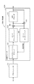
- FIG. 1 shows a block diagram of a typical transmitter 100 that uses a rotating constellation with a pseudo cyclic low density parity check (QC LDPC) code.
- the block diagram of FIG. 1 shows only the blocks related to the present invention.
- the transmitter 100 includes an LDPC encoder 110, a bit interleaver 120, a QAM mapper 130, a constellation rotator 140, and a modulator 150.
- the transmitter 100 receives a binary block having a predetermined length including information to be transmitted as an input.
- LDPC encoder 110 first encodes each information block using a low density parity check code (eg, a pseudo cyclic low density parity check code including a repeat accumulating pseudo cyclic low density parity check code). To do.
- a low density parity check code eg, a pseudo cyclic low density parity check code including a repeat accumulating pseudo cyclic low density parity check code.
- This encoding process includes calculation of redundant bits and addition of the redundant bits to the information block in order to make the error tolerance of the information block stronger.
- the bit interleaver 120 interleaves a plurality of bits of an LDPC codeword (hereinafter referred to as “LDPC block”) obtained by encoding (bit interleaving).
- LDPC block an LDPC codeword obtained by encoding (bit interleaving).
- the QAM mapper 130 maps a plurality of interleaved bits of the LDPC block to complex QAM (quadrature amplitude modulation) symbols.
- the real and imaginary components of the complex QAM symbol are modulated independently of each other.
- Each of the real and imaginary components is an encoded number of bits. This predetermined number is denoted by B. Therefore, a complex QAM symbol is a 2 ⁇ B bit encoded.
- the real and imaginary components can be regarded as PAM (pulse amplitude modulation) symbols or ASK (amplitude shift keying) symbols, respectively.
- This PAM symbol takes one value from a discrete set containing 2 B values. It is well known how the B bits are mapped to PAM symbols and is not directly related to the present invention.
- An aspect relevant to the present invention is that each FEC block is converted into a block of (real) PAM symbols, two of which become one complex QAM symbol.
- the QAM mapper 130 receives a plurality of bits output from the bit interleaver 120, and continuously outputs PAM symbols by mapping consecutive B bits to one PAM symbol.
- the QAM mapper 130 corresponds to a constellation mapper that performs constellation mapping of each group of B bits of the FEC block after interleaving to a real-valued symbol.
- a PAM symbol corresponds to a real value symbol.
- the constellation rotator 140 applies dedicated transforms to a plurality of QAM symbols generated by the QAM mapper 130 and outputs a plurality of complex symbols.
- a set of D PAM symbols for each D-dimensional vector is considered to represent a unique point in the D-dimensional space. Therefore, a combination of D B forms a D-dimensional constellation. Therefore, matrix multiplication is regarded as rotation in the D-dimensional space.
- the term “rotated constellation” is used. Only the special structure of the D ⁇ D square orthogonal matrix (rotation matrix) described above is not relevant to the present invention.
- the orthogonal matrix used by the constellation rotator 140 is, for example, an orthogonal matrix in which the values of the elements of each dimension of the D-dimensional vector are distributed in at least two dimensions.
- An example of such an orthogonal matrix is a matrix in which the absolute values of all elements on the main diagonal are equal to the first value, and the absolute values of all elements not on the main diagonal are equal to the second non-zero value. Can do.
- the orthogonal matrix R is a
- a and b are actual parameters, and sign values (Sign Value) s i, j are
- D converted PAM symbols (D components of each rotation constellation) that are elements of each D-dimensional rotation vector are D different complex. Must be mapped to a symbol. Complex symbols are also called complex cells or cells. Furthermore, the D components of the rotational constellation are preferably spread in time and frequency so that the channel fading to which they are affected is as uncorrelated as possible.
- the modulator 150 modulates the complex symbol, and the modulated complex symbol is transmitted on the communication medium.
- the modulation scheme may be, for example, OFDM (orthogonal frequency-division multiplexing). Additional interleaving in time and frequency is typically performed prior to modulation to increase system diversity.
- bit interleaver 120 disposed between the LDPC encoder 110 and the QAM mapper 130 can efficiently implement a receiver in a system using a rotation constellation together with a QC LDPC code. It is disclosed how it can be optimized to do.
- the LDPC code is a linear error correction code that is completely defined by a parity check matrix (PCM).
- the parity check matrix is a binary sparse matrix that represents a connection between a codeword bit (also referred to as a variable node) and a parity check (also referred to as a check node).
- the columns and rows of the parity check matrix correspond to variable nodes and check nodes, respectively.
- the connection between the variable node and the check node is represented by an entry of “1” (matrix element value “1”) in the parity check matrix.
- QC LDPC code is a structure particularly suitable for hardware implementation. In fact, most standards today employ QC LDPC codes. Such a parity check matrix of the QC LDPC code has a special structure having a cyclic matrix.
- a cyclic matrix is one in which each row is a cyclic shift of one element in the previous row, and may have one, two, or more cyclically-shifted diagonals. , A square matrix.
- the size of each cyclic matrix is Q rows and Q columns (Q ⁇ Q), and Q is called a cyclic factor of the QC LDPC code.
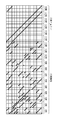
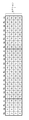
- the parity check matrix of FIG. 2 includes a cyclic matrix having 1 or 2 cyclically shifted diagonal lines. However, in the parity check matrix of FIG. 2, matrix elements having a value of “1” are represented by black squares, and matrix elements having a value of “0” are represented by white squares.
- the codeword bits are divided into Q-bit blocks.
- This Q-bit block is referred to as a cyclic block or a pseudo cyclic block throughout this document, and is denoted as “QB”.
- the QC LDPC code of the parity check matrix shown in FIG. 2 belongs to a special type of QC LDPC code called repeat-accumulate (RA) QC LDPC code.
- the RA QC LDPC code is well known for its ease of encoding, and the second generation DVB standards (DVB-S2 (Non-Patent Document 2), DVB-T2 (Non-Patent Document 1), DVB-C2 (Non-Patent Document 1)) It is adopted in many standards such as Patent Document 3)).
- the right side (parity part) corresponding to the parity bit of the parity check matrix has a structure in which the arrangement position of the element “1” is stepped. These aspects are well known in the art.
- the left side of the parity check matrix is a portion (information portion) corresponding to the information bit.
- bit interleaver is called a parallel bit interleaver and is characterized by a high degree of parallelism.
- a parallel bit interleaver enables a particularly efficient hardware implementation.
- FIG. 3 shows an example of the bit interleaver 120 shown in FIG. 1, and includes a parallel bit interleaver 121 for QC LDPC codes.
- the number of pseudo cyclic blocks per codeword is denoted as N.
- the multiple pseudo cyclic blocks of 1LDPC block are divided into multiple sections (also referred to as interleaver sections or bit interleaver sections in this document), and each section is interleaved separately using section permutation.
- the section permutation performed for each section may be the same rule.
- 12 pseudo cyclic blocks QB1 to QB12 are divided into three sections 1 to 3.
- FIGS. 5A and 5B corresponds to one bit of the LDPC codeword.
- the writing order and the reading order are indicated by arrows, respectively.
- interleaving described with reference to FIGS. 5A and 5B is so-called column-row interleaving.
- the output of the section interleaver is composed of a group of M bits (one column bit of the matrix), and the M bits belong to M different cyclic blocks of the original LDPC block. .
- the arrangement order of the pseudo cyclic blocks in the LDPC codeword may be changed in accordance with a predetermined permutation, and the permutation is determined by pseudo cyclic block permutation (QB). Called permutation).
- QB pseudo cyclic block permutation
- an additional permutation may be applied to the Q bits of each pseudo cyclic block, and the permutation is performed in the pseudo cyclic block. This is called an intra-QB permutation and is typically a cyclic shift. Typically, the shift value is different for each cyclic block, but may be the same.
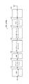
- FIG. 6 shows a configuration example of a bit interleaver having QB permutation and intra-QB permutation functions.
- the bit interleaver 120a includes a section interleaver 121 that executes section permutation, a QB interleaver 123 that executes QB permutation, and an intra-QB permutation that executes intra-QB permutation.
- Lever 125-1 to 125-12 are provided.
- QB and intra-QB permutation are important for optimizing communication performance, but they are not directly related to the present invention.
- QB and intra-QB permutation can be considered part of the definition of LDPC codes.
- QB permutation is equivalent to column permutation of a pseudo cyclic block in the original parity check matrix.
- the cyclic shift (intra-QB cyclic shift) performed in intra-QB permutation is equivalent to further cyclically shifting the original cyclically shifted diagonal line in the parity check matrix by (qmodQ).
- q is a shift value for cyclically shifting Q bits by intra-QB permutation.
- An intra-QB cyclic shift with the same shift value is applied to all diagonals of all pseudo cyclic blocks in the same column of the parity check matrix.
- This mapping technique involves mapping each QAM constellation to two adjacent columns of the section permutation matrix. This is equivalent to selecting the bit interleaver parameter M (number of pseudo cyclic blocks per section) to be equal to B (number of bits per PAM symbol). Therefore, each PAM symbol is modulated by successive B bits in one column of the section permutation matrix (see FIGS. 5A and 5B). This is the preferred mapping technique for regular (non-rotating) QAM constellations.
- one square in FIGS. 7A and 7B corresponds to one bit of the LDPC codeword.
- one square in FIG. 7D corresponds to one PAM symbol (a real component or an imaginary component of the QAM symbol).
- a process equivalent to writing in the row direction to the matrix with 2 columns and reading the written 16 bits from the matrix in the column direction as shown in FIG. 7B is performed.
- the writing order and the reading order are indicated by arrows, respectively.
- the QAM mapper 130 creates and outputs the real component (4-PAM) of the QAM symbol from the 2 bits of the first column of this matrix, and then the second column of the matrix.
- the imaginary number component (4-PAM) of the QAM symbol is generated from the two bits of and output. As a result of this being repeated, the output of the QAM mapper 130 is as shown in FIG.
- the constellation rotator 140 applies the first rotation processing to the D PAM symbols (components) of the adjacent D QAM symbols output from the QAM mapper 130, and the same D A second rotation process is applied to the remaining D components of the QAM symbols.
- the constellation rotator 140 then outputs a complex symbol (cell) in which the result of the first rotation process is a real component and the result of the second rotation process is an imaginary component.
- the constellation rotator 140 applies one of the two rotation processes to the D real components of the adjacent D QAM symbols, and applies the other to the D imaginary components of the same D QAM symbols. It is preferable.
- one square in FIG. 7E represents one component of a complex symbol (cell).
- consecutive (adjacent) D complex symbols (cells) are called constellation blocks.
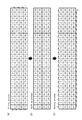
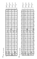
- FIG. 8 and 9 show examples of mapping of the output of the bit interleaver 120 to a non-rotation constellation and a (four-dimensional rotation) constellation block.
- the cyclic coefficient Q is 24 and the number of sections is 8. Note that a set of two squares surrounded by a thick line in FIG. 8 corresponds to one complex symbol (cell). Further, a set of eight squares surrounded by a thick line in FIG. 9 corresponds to a four-dimensional rotation constellation block.
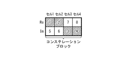
- the structure of this constellation block is the structure shown in FIG.
- mapping method of the LDPC block to the constellation block in the rotation constellation makes the structure of the receiver more complicated. This is because the number of bits mapped from each pseudo cyclic block of the bit interleaver section corresponding to the constellation block to the constellation block depends on the dimension D of the rotation constellation. More specifically, as explained above, the number of constellation blocks is 2 ⁇ D because it encodes 2 ⁇ B ⁇ D codeword bits. This is not necessarily the only problem. However, if the same receiver needs to support different dimensionality (eg, 1, 2, 4, 8), its implementation efficiency is compromised. This is especially true for receivers that use iterative decoding.
- 10A and 10B show general block diagrams of a receiver using non-iterative decoding and iterative decoding, respectively.
- processing blocks that perform substantially the same processing are denoted by the same reference numerals, and redundant description is omitted.
- 10A includes a demodulator 210 and a non-iterative decoder 220 (including a constellation demapper 230, a bit deinterleaver 250, and an LDPC decoder 270). 1 and 10A that the receiver 200 using non-iterative decoding has a structure corresponding to the transmitter 100 of FIG.
- the demodulator 210 demodulates the input signal and outputs N ⁇ Q / (2 ⁇ B) complex symbols (cells).
- the constellation demapper 230 performs derotation and QAM demapping on N ⁇ Q / (2 ⁇ B) complex symbols to calculate (soft) bits. However, the constellation demapper 230 performs derotation and QAM demapping separately for D components corresponding to the D converted PAM symbols of the transmission-side D-dimensional rotation constellation. Note that the structure of the receiver 200 does not uniquely correspond to the structure of the transmitter 100 in that derotation and QAM demapping are performed by one block, that is, the constellation demapper 230. Combining and executing these two operations is a necessary condition for optimum decoding performance.
- the bit deinterleaver 250 deinterleaves a plurality of (soft) bits. Note that deinterleaving uses a permutation rule opposite to interleaving in order to return to the order before interleaving by the bit interleaver 120 of the transmitter 100.
- the LDPC decoder 270 decodes the deinterleaved (soft) bits. Note that the decoding process by the LDPC decoder 270 is based on the LDPC code used by the LDPC encoder 110 of the transmitter 100 for the encoding process.
- 10B includes a demodulator 210 and an iterative decoder 320 (including a constellation demapper 330, a bit deinterleaver 250, an adder 350, an LDPC decoder 370, a subtractor 380, and a bit interleaver 390).
- a demodulator 210 includes a demodulator 210 and an iterative decoder 320 (including a constellation demapper 330, a bit deinterleaver 250, an adder 350, an LDPC decoder 370, a subtractor 380, and a bit interleaver 390).
- the bit interleaver 390 interleaves input external information (extrinsic information).
- the interleaving of the external information uses the same permutation rules as the interleaving performed by the bit interleaver 120 of the transmitter 100.
- FIG. 11 shows a detailed block diagram of the iterative decoder 220B of FIG. 10B.
- the bit interleaver 390 and the bit deinterleaver 250 are omitted in FIG.
- Cell memory 315 stores complex symbols (cells) created by demodulator 210.
- the cells stored in the cell memory 315 are used by the constellation demapper 330 through an iterative decoding process.
- the APP memory 335 stores a posterior probability (APP) of bits and is continuously updated in the decoding process.
- the buffer memory 355 is created by the constellation demapper 330 and stores initial posterior probabilities necessary for calculating external posterior probability information (extrinsicba-posteriori probability information).
- the constellation demapper 330 performs derotation and QAM demapping in one block, like the constellation demapper 230.
- the constellation demapper 330 performs derotation and QAM demapping by dividing into D components corresponding to the D converted PAM symbols of the transmission-side D-dimensional rotation constellation.
- the constellation demapper 330 receives no a-priori information from the LDPC decoder 370 and deconstructs the complex symbols stored in the cell memory 315 without assistance from the prior information. Run the mapping. This demapping involves extracting soft bits from the cells stored in the cell memory 315. Soft bits (a measure of the posterior probability of a bit, typically expressed as a log likelihood ratio) obtained by demapping are directly written into the APP memory 335 and the buffer memory 355. That is, in the first iteration, the adder 350 adds 0 to the output of the constellation demapper 330 and outputs the result to the APP memory 335.
- the LDPC decoder 370 When the soft bits of the LDPC codeword are written in the APP memory 335, the LDPC decoder 370 performs one or more LDPC decoding iterations using the soft bits written in the APP memory 335, and uses the execution result to execute the APP memory. The stored contents of 335 are updated. Note that the decoding process by the LDPC decoder 370 is based on the LDPC code used by the LDPC encoder 110 of the transmitter 100 for the encoding process. This processing content is known in the art.
- an outer iteration is performed using the constellation demapper 330. This outer iteration includes the following steps (A) to (C).
- the subtractor 380 calculates external information by subtracting the initial posterior probability stored in the buffer memory 355 from the updated posterior probability stored in the APP memory 335, and obtains the external information in advance. (A-priori information) to constellation demapper 330.
- the constellation demapper 330 calculates the update soft bit using the cell and the prior information stored in the cell memory 315.
- the adder 350 adds the external information to the update soft bit, and writes the addition result back to the APP memory 335.
- the LDPC decoder 370 executes one or more LDPC decoding iterations using the soft bits written in the APP memory 335 again, and updates the stored contents of the APP memory 335 using the execution results.
- FIG. 12 A more detailed structural example of a parallel iterative decoder for QC LDPC codes is shown in FIG. 12 for a non-rotating constellation (see FIG. 8).
- the parallel iterative decoder shown in FIG. 12 as an example of the structure exactly matches the structure of the iterative decoder 320 shown in FIG. 11 except for the cell memory excluded for the sake of clarity.
- the structure of the parallel iterative decoder of FIG. 12 has a high degree of parallelism.
- the constellation demapper has several identical demappers and allows very high throughput (processing power, throughput).
- a structure with a high degree of parallelism is made possible by the inherent parallel structure of the QC LDPC code and the bit interleaver structure described above.
- the LDPC decoder includes a cyclic shifter and a check node unit (denoted as a CN unit in the figure).
- One cyclic shifter cyclically shifts the a posteriori probability of one pseudo cyclic block sequentially supplied from the APP memory by a predetermined number of times.
- the check node unit performs decoding using the posterior probability of the cyclically shifted bit to update the posterior probability of the bit.
- the other cyclic shifter performs a predetermined number of cyclic shifts so that the a posteriori probability of the updated bit for one pseudo cyclic block sequentially supplied from the check node unit cancels the cyclic shift by one cyclic shifter.
- the LDPC decoder is a technique well known in the art. For this reason, further explanation is omitted.
- FIG. 13 shows a structural example of a parallel non-repetitive decoder for QC LDPC codes.
- the parallel non-iterative decoder has no buffer memory, no adder or subtracter, and the demapper has no input of prior information. There is usually no cell memory.
- APP memory is typically implemented using several memory banks in parallel.
- the designer can arbitrarily select a divisor of Q as the number of memory banks.
- the number of memory banks is represented by P, which is a measure of parallelism. Therefore, the number of memory banks is one of the most important design parameters.
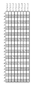
- FIG. 14 shows an example of storage of (soft) bits of the LDPC block in the memory bank of the APP memory.
- one square in FIG. 14 represents one (soft) bit of the LDPC block, and the number in the square indicates the address of each bit in the corresponding memory bank.
- the hatched squares indicate bits in the first memory bank.
- a new aspect of this implementation is that a similar bank memory structure is used for the cell memory 315 shown in FIG.
- the cell memory 315 is not shown in FIG. 12, but is an indispensable part of iterative decoding.
- the memory arrangement of the cell memory 315 is as shown in FIG. Accordingly, the real and imaginary components of the complex symbol (cell) are stored in the odd and even banks, respectively. Note that a pair of two squares surrounded by a thick line in FIG. 15 corresponds to a pair of real number components and imaginary number components of the same cell.
- a plurality of demappers constituting the constellation demapper are arranged between the memory bank of the cell memory and the memory bank of the APP memory. According to an aspect of the present invention, a plurality of demappers are also divided into demapper banks.
- the number of demapper banks is equal to half the number of memory banks. The reason is that each demapper needs to access both real and imaginary components stored in different memory banks.
- the demapper bank includes one or more demappers.
- the number of demappers in the demapper bank is preferably selected such that the total number of demappers is a divisor or multiple of Q. Therefore, in the scenario shown in FIG.
- the total number of demappers is a divisor of Q (1, 2, 3, 4, 6, 8, 12, 24) or a multiple of Q (24, 48,.
- the number of demappers per demapper bank can be any multiple of 1, 2, 4, and 4 so that the number of demappers is 24. This number of demappers per demapper bank is a design parameter and directly determines the maximum throughput achieved by iterative decoding.
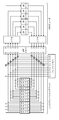
- FIG. 12 It is important to understand how the wiring diagram shown in FIG. 12 is efficient for implementing the actual hardware structure. Due to the high degree of parallelism and local data transfer, the hardware structure shown in FIG. 16 is very compact and regular. This significantly reduces the amount of wiring paths, and thus signal propagation delay and hardware area, which allows for cheap and fast implementation. In FIG. 16, it should be noted that the adder and subtracter of FIG. 12 are included in the demapper bank for more clarity.
- each demapper bank is connected to two adjacent memory banks of each of three memories (cell memory, APP memory, buffer memory). These memory banks can easily be placed in the immediate vicinity of their associated demapper bank.
- each constellation block encodes adjacent 2 ⁇ D bits of each pseudo cyclic block, each demapper needs to be connected to 2 ⁇ D memory banks. This makes the wiring path very complicated because different wiring arrangements are required for each value of D.
- the degree of freedom of the designer is limited by the fact that the number of memory banks must be 2 ⁇ D in the selection of the number of memory banks (that is, the parallelism of the LDPC decoder).
- each demapper bank is connected to only two memory banks regardless of the value of D. The present invention achieves this.
- the mapping of the bits of the LDPC block (bit interleaver output bits) to the constellation block is the same for the two D-dimensional vectors forming the constellation block. It is made from a group of quasi-cyclic blocks and is implemented such that each of the two D-dimensional vectors encodes only one bit of the same quasi-cyclic block.
- the four hatched PAM symbols in the constellation block form one 4D rotation constellation of the (4D rotation) constellation block, and the four non-hatched PAM symbols form the other 4D rotation constellation. Form.
- the difference from the technique shown in FIG. 9 can be easily understood.
- this mapping arrangement can be realized by selecting the parameter M (number of pseudo cyclic blocks per 1-bit interleaver section) to be equal to B ⁇ D instead of B described above. . Accordingly, the number of bit interleaver sections is reduced from N / B to N / (B ⁇ D) (for example, 8 to 2 in the examples of FIGS. 9 and 17).
- B 1, 2, 3, 4
- B 1, 2, 3, 4
- D 1, 2, 3, 4
- the transmitter 100A includes an LDPC encoder 110, a bit interleaver 120A, a QAM mapper 130A, a constellation rotator 140A, and a modulator 150.
- the processing contents of the LDPC encoder 110 and the modulator 150 can be applied to those explained in the transmitter 100 in FIG.
- the bit interleaver 120A separates N / (B ⁇ D) sections separately from each other so that the Q bits of each B ⁇ D pseudo cyclic block are mapped to Q bit groups bit by bit. Interleave the (B ⁇ D) bits using section permutation (section interleaving).
- Step 2 The QAM mapper 130A maps each group of consecutive B bits output from the bit interleaver 120A to a PAM symbol.
- the constellation rotator 140A for each group of adjacent 2 ⁇ D PAM symbols, includes a first D-dimensional vector having adjacent D PAM symbols as elements and adjacent D PAMs Compute a first D-dimensional rotation vector and a second D-dimensional rotation vector by multiplying a second D-dimensional vector whose elements are symbols by an orthogonal matrix (applying the first rotation and the second rotation) ).
- the orthogonal matrix exemplified in the constellation rotator 140 of FIG. 1 is used.
- the constellation rotator 140A includes the first D-dimensional vector and 2 ⁇ 2 which are composed of D PAM symbols formed from bits of one column of (2 ⁇ j ⁇ 1) columns of the section permutation matrix.
- a first D-dimensional rotation vector and a second D-dimensional rotation vector are obtained by multiplying a second D-dimensional vector having D PAM symbols formed from bits of one column of j columns by an orthogonal matrix. Is calculated (the first and second rotations are applied). However, the orthogonal matrix illustrated in the constellation rotator 140 of FIG. 1 is used for multiplication. Note that the first D-dimensional vector and the second D-dimensional vector form one constellation block.
- Step 4 The constellation rotator 140A uses the D converted PAM symbols of the first D-dimensional rotation vector as the adjacent D complex symbols (cells) or the D real numbers or imaginary numbers of the non-adjacent D complex symbols. Mapping to the component, D converted PAM symbols of the second D-dimensional rotation vector are mapped to the remaining D real or imaginary components of the D cells and output.
- each of the D transformed PAM symbols of the first D-dimensional rotation vector and the second D-dimensional rotation vector is mapped to D real components and D imaginary components of adjacent D cells.
- the respective D transformed PAM symbols of the first D-dimensional rotation vector and the second D-dimensional rotation vector are mapped to D imaginary components and D real components of adjacent D cells.
- one square represents one converted PAM symbol.
- Numbers 1 to 4 in the square correspond to the converted PAM symbol of the first D-dimensional rotation vector
- numbers 5 to 8 correspond to the converted PAM symbol of the second D-dimensional rotation vector.
- the converted PAM symbols in which the numbers in the squares of FIG. 19A and FIGS. 19B and 19C described later match the numbers in the squares of FIG. 17 are the same.
- FIG. 21 shows the details of (Step 2) and (Step 4) in FIG. 20
- FIG. 21 (b) shows the details of (Step 3) and (Step 4) in FIG. 20.
- FIG. 22 shows the result of mapping the PAM symbol created in FIG. 21A to the non-rotated constellation block.
- receivers 200A and 300A of the present embodiment corresponding to transmitter 100A of FIG. 18 will be described with reference to FIGS. 23A and 23B.
- processing blocks that perform substantially the same processing as in FIGS. 10A and 10B are denoted by the same reference numerals, and redundant description is omitted.
- the receiver 200A is a receiver that performs non-iterative decoding, and includes a demodulator 210 and a non-iterative decoder 220A (constellation demapper 230, bit deinterleaver 250A, LDPC decoder 270).
- the receiver 300A is a receiver that performs iterative decoding, and includes a demodulator 210 and an iterative decoder 320A (constellation demapper 330, bit deinterleaver 250A, adder 350, LDPC decoder 370, subtractor 380, bit interleaver. 390).
- the constellation demappers 230 and 330 perform processing (derotation and QAM demapping) reflecting QAM mapping by the QAM mapper 130A and rotation (see steps 2 to 4 in FIG. 20) by the constellation rotator 140A in one block. Is what you do.
- This interleaving uses the same permutation rules as the section interleaving performed by the bit interleaver 120A of the transmitter 100A.
- non-iterative decoder 220A and the iterative decoder 320A can use the detailed structure or the parallel structure described with reference to FIGS.
- a function of executing QB permutation and / or intra-QB permutation may be added to the bit interleaver 120A of the transmitter 100A before section interleaving (see FIG. 6).
- a function of executing intra-QB permutation and / or interleaving of rules opposite to QB permutation after section deinterleaving is added to the bit deinterleaver 250A, and What is necessary is just to add the function to perform the interleaving of the same rule as QB permutation and / or intra-QB permutation before interleaving.
- FIG. 24 shows another block diagram of a typical transmitter that uses a rotating constellation with a quasi-cyclic low density parity check (QC LDPC) code.
- QC LDPC quasi-cyclic low density parity check
- the transmitter 500 has a structure in which a component interleaver 530 and a cell interleaver 550 are added to the transmitter 100 of FIG.
- the component interleaver 530 interleaves the D converted PAM symbols (D components of each rotation constellation) of each D-dimensional rotation vector so as to spread over the entire FEC block. Note that a block interleaver is normally used as the component interleaver 530.
- the cell interleaver 550 interleaves a plurality of output cells of the component interleaver 550 using a pseudo-random bit sequence (PRBS).
- PRBS pseudo-random bit sequence
- the plurality of cells of each FEC block are further distributed in time and frequency by a time interleaver and a frequency interleaver, respectively.
- the time interleaver and the frequency interleaver are arranged between the cell interleaver 550 and the modulator 150, but are omitted for simplification of illustration.
- the block interleaver used for the component interleaver 530 is designed regardless of the QC LDPC code pseudo cyclic structure. For this reason, the component interleaver 530 created by the block interleaver cannot easily perform parallelization based on the pseudo cyclic structure of the LDPC code. Since the component interleaver 530 is not suitable for parallelization, efficient implementation is hindered particularly for receivers using iterative decoding.
- another object of the present invention is to disclose a component interleaver that can be implemented in parallel, which enables highly efficient hardware implementation. Furthermore, the disclosed component interleaver has a structure similar to that of the bit interleaver.
- a transmitter 500A according to the present embodiment including a component interleaver capable of parallelization will be described with reference to FIG.
- processing blocks that perform substantially the same processing as in FIGS. 1 and 24 are denoted by the same reference numerals, and redundant description is omitted.
- Transmitter 500A includes LDPC encoder 110, bit interleaver 115A, QAM mapper 130A, component deinterleaver 510A, constellation rotator 520A, component interleaver 530A, cell interleaver 550A, and modulator 150.
- the bit interleaver 115A separates the N ⁇ M sections into the section perm and the Q ⁇ M bits so that the Q bits of each of the M pseudo cyclic blocks are mapped to Q bit groups one bit at a time.
- Interleave using station section interleaving. This section interleaving is, for example, a process equivalent to writing Q ⁇ M bits in the order of input to a section permutation matrix of Q columns and M rows in the row direction and reading the written Q ⁇ M bits from the matrix in the column direction. It is realized by doing.
- the component deinterleaver 510A divides the N ⁇ Q / B PAM symbols output from the QAM mapper 130A into N / (B ⁇ D) sections.
- Component deinterleaver 510A deinterleaves Q ⁇ D PAM symbols (components) separately in N / (B ⁇ D) sections (component deinterleaving).
- Component deinterleaving uses a permutation rule opposite to component interleaving by component interleaver 530A described later. Details of the processing contents of the component deinterleaver 510A will be described later.
- the constellation rotator 520A multiplies each D-dimensional vector having D PAM symbols output continuously from the component deinterleaver 510A as vector elements by an orthogonal matrix.
- a D-dimensional rotation vector having D converted PAM symbols as elements is calculated.
- the orthogonal matrix illustrated in the constellation rotator 140 of FIG. 1 is used for multiplication.
- each constellation block encodes only 2 bits of the same pseudo cyclic block, and these 2 bits are constellation blocks obtained by encoding these 2 bits.
- One bit is mapped to the same dimension of two D-dimensional vectors to be formed.
- the component interleaver 530A interleaves Q ⁇ D converted PAM symbols separately in N / (B ⁇ D) sections (component interleaving). This section corresponds to the section of component deinterleaver 510A.
- Q ⁇ D transformed PAM symbols are written in a column direction in a matrix of Q columns and D rows in the order of input, and an appropriate cyclic shift (shift value is 0 and Q ⁇ ) in each row. 1), and cyclically shifted Q ⁇ D transformed PAM symbols are read out from this matrix in the row direction, and processing is performed. This distributes the D transformed PAM symbols of each D-dimensional rotation vector as evenly as possible in the section.
- Component deinterleaving in each corresponding section is performed by, for example, writing Q ⁇ D PAM symbols in a row direction in a matrix of Q columns and D rows in the order of input, and the cyclic shift and accurate application to each row by the component interleaver 530A. This is realized by applying a reverse cyclic shift to and performing a process equivalent to reading the cyclically shifted Q ⁇ D PAM symbols in the column direction from this matrix.
- cyclic shift is applied according to cell granularity. That is, the shift value is preferably an even number, that is, a multiple of 2.
- the constellation block of the bits of the LDPC block (the output bit of the bit interleaver) is processed by the processing of the bit interleaver 115A and the component deinterleaver 510A and by the processing of the bit interleaver 115A and the component deinterleaver 510B described later. Mapping is performed such that each D-dimensional vector forming the constellation block is made from the same group of pseudo cyclic blocks, and each D-dimensional vector encodes only one bit of the same pseudo cyclic block. It has been done.
- non-TFS in component interleaving in each section, a cyclic shift whose shift value is Q / D increased from the cyclic shift applied to the previous row is applied to each row of the matrix.
- the processing contents of the component deinterleaver 510A and the component interleaver 530A relating to this example will be described. However, this processing corresponds to one section of the component deinterleaver 510A and the component interleaver 530A.
- the implementation of component interleaving using cyclic shift disclosed in the present invention has the advantage of sufficiently reducing hardware complexity, especially in the case of a receiver using iterative decoding.
- the component interleaver 530A maps two consecutive converted PAM symbols read from the matrix into complex symbols in pairs. As a result, D ⁇ Q / 2 complex cells are obtained per section.
- the cell interleaver 550A additionally interleaves N ⁇ Q / (2 ⁇ B) cells in all sections (cell interleaving).
- N ⁇ Q / (2 ⁇ B) cells are written in the row direction in a matrix of Q / 2 columns N / B rows in the order of input, and N ⁇ Q / (2 ⁇ B) written. This is realized by performing a process equivalent to reading cells from this matrix in the column direction.
- the writing order and the reading order are indicated by arrows, respectively.
- the numbers in the squares indicate the input order of the cells.
- the hunted squares represent D complex symbols (cells) that carry 2 ⁇ D components of the first D-dimensional rotational constellation. It can clearly be seen that the cell interleaver 550A does not depend on the parameter D.
- the cell interleaver 550A writes 96 cells in the row direction into a matrix of 12 columns and 8 rows in the input order, as shown in FIGS. 28B and 29B.
- the 96 cells written are read out from this matrix in the column direction.
- FIGS. 30A and 30B show output examples of the cell interleaver 550A.
- 30 (a) shows the processing results of FIGS. 28 (a) and 28 (b)
- FIG. 30 (b) shows the processing results of FIGS. 29 (a) and 29 (b).
- D cells in the first constellation block are hatched.
- 30 (a) and 30 (b) it can be seen that the D cells of the first constellation block extend fairly evenly over the entire LDPC block.
- FIG. 31A processing blocks that perform substantially the same processing as those in FIGS. 1, 24, and 25 are denoted by the same reference numerals, and redundant description is omitted.
- the component deinterleaver 510A is in the subsequent stage of the QAM mapper 130A, whereas in the transmitter 500B in FIG. 31A, the component deinterleaver 510B is in the previous stage of the QAM mapper 130A. .
- Component deinterleaver 510B groups B bits (bits for one PAM symbol) in the order of output of bit interleaver 115A, regards the group of B bits as one PAM symbol, and performs the same perm as component deinterleaver 510A. Deinterleave using a station.
- 31B performs the mapping performed by the QAM mapper 130A of the transmitter 500B of FIG. 31A and the rotation performed by the constellation rotator 520A by one block, that is, the rotation constellation mapper 570.
- 2 ⁇ B ⁇ D bits are directly mapped to the rotation constellation block.
- FIG. 31B The arrangement shown in FIG. 31B enables more efficient mounting.
- bit interleaver 115A of the transmitters 500A, 500B, and 500C may be added to the bit interleaver 115A of the transmitters 500A, 500B, and 500C (see FIG. 6).
- the component deinterleaver 510B applies component deinterleaving to bits.
- bit interleaver 115A performs intra-QB permutation based on cyclic shift
- component deinterleaver 510B and bit interleaver 115A have the same structure based on cyclic shift. For this reason, the component deinterleaver 510B can be incorporated in the bit interleaver 115A.
- the shift value of the cyclic shift applied to each row by the component deinterleaver 510B is changed to the shift value of the cyclic shift in intra-QB permutation applied to the B pseudo cyclic blocks mapped to the row. to add.
- the cyclic shift in the intra-QB permutation is itself incorporated in the definition of the QC LDPC code. That is, the cyclic shift performed by the component deinterleaver 510B can be incorporated into the definition of the QC-LDPC code together with the cyclic shift performed by the intra-QB permutation performed by the bit interleaver 115A.
- the component deinterleaver of the transmitter and the corresponding component interleaver of the receiver are not necessary in hardware implementation.
- receiver 700 according to the present embodiment corresponding to transmitter 500C in FIG. 31B will be described with reference to FIG.
- the receiver 700 in FIG. 32 reflects the function of the transmitter 500C in FIG. 31B
- the receiver 700 in FIG. 32 corresponds to the transmitter 500A in FIG. 25 and the transmitter 500B in FIG.
- processing blocks that perform substantially the same processing as in FIGS. 10A and 10B are denoted by the same reference numerals, and redundant description is omitted.
- the receiver 700 includes a demodulator 210, a cell deinterleaver 720, a component deinterleaver 730, a rotation constellation demapper 740, a component interleaver 750, a bit deinterleaver 760, and an LDPC decoder 270.
- the cell deinterleaver 720 deinterleaves the N ⁇ Q / (2 ⁇ B) cells created by the modulator 210 in order to reorder them before reordering by the cell interleaver 550A of the transmitter 500C (cell Deinterleave).
- This cell deinterleaving uses a permutation rule opposite to cell interleaving.
- N ⁇ Q / (2 ⁇ B) cells of one FEC block are written in the column direction in a matrix of Q / 2 columns N / B rows in the order of input, and the written N ⁇ Q / ( This is realized by performing a process equivalent to reading 2 ⁇ B) cells from this matrix in the row direction.
- the component deinterleaver 730 receives N ⁇ Q / (2 ⁇ B) cells output from the cell deinterleaver 720 from the N ⁇ Q / (2 ⁇ B) cells in order to restore the order before the reordering by the component interleaver 530A of the transmitter 500C. Extract Q / B components, divide the extracted N ⁇ Q / B components into N / (B ⁇ D) sections, and separate N / (B ⁇ D) sections with Q ⁇ Deinterleave D components (component deinterleaving). This component deinterleaving uses a permutation rule opposite to the component interleaving performed by the component interleaver 530A.
- Rotational constellation demapper 740 sequentially demaps a cell that is a pair of two consecutive components input from component deinterleaver 730, extracts (soft) bits, and outputs them to component interleaver 750.
- the rotation constellation demapper 750 performs the constellation derotator and QAM demapping in one block.
- the rotation constellation demapper 740 performs derotation and QAM demapping by dividing into D components corresponding to D converted PAM symbols of the transmission-side D-dimensional rotation constellation.
- the decoding performance can be improved by combining and mounting these two operations. This aspect is well known in the art.
- the component interleaver 750 outputs N ⁇ Q (soft) bits output from the rotation constellation demapper 740 to N / (B in order to restore the order before the reordering by the component deinterleaver 510B of the transmitter 500C.
- Divided into ( ⁇ D) sections, and divided into N / (B ⁇ D) sections, and B (soft) bits are grouped (herein referred to as “(soft) bit groups”)).
- Interleave multiple (soft) bit groups (component interleaving). This component interleaving uses a permutation rule opposite to the component deinterleaving performed by the component deinterleaver 510B.
- Component interleaving in each section is, for example, a cyclic shift in which Q ⁇ D (soft) bit groups are written in the column direction in a matrix of Q columns and D rows in the input order, and the component deinterleaver 510B is applied to the corresponding row in each row. Is realized by applying a reverse cyclic shift exactly and performing a process equivalent to reading the cyclically shifted Q ⁇ D (soft) bit groups from this matrix in the row direction.
- bit deinterleaver 760 A function for executing inter-QB permutation and / or rule interleaving opposite to QB permutation after section deinterleaving may be added.
- the component deinterleaver 510B can be incorporated into the bit interleaver 115A.
- the cyclic shift by component interleaver 750 can be incorporated into a cyclic shift associated with intra-QB permutation performed by bit deinterleaver 760.
- the cyclic shift by the component interleaver 750 can be incorporated into the definition of the LDPC code together with the cyclic shift related to the intra-QB permutation executed by the bit deinterleaver 760. Therefore, the component interleaver 750 need not be implemented in hardware.
- FIG. 33A shows the area behind the cell deinterleaver 720 of FIG.
- processing blocks that perform substantially the same processing as in FIGS. 10A, 10B, and 32 are denoted by the same reference numerals, and redundant description is omitted.
- a bit interleaver and a bit deinterleaver corresponding to the bit interleaver 115A of the transmitters 500B and 500C are not included because they are not necessary for hardware.
- the receiver 700A includes a component deinterleaver 730, a rotation constellation demapper 740A, a component interleaver 750, an adder 770, an LDPC decoder 370, a subtractor 780, and a component deinterleaver 790.
- the component deinterleaver 790 divides the N ⁇ Q external information output from the subtractor 780 into N / (B ⁇ D) sections, and separately separates the N / (B ⁇ D) sections into B
- the pieces of external information are grouped (herein referred to as “external information groups”), and Q ⁇ D external information groups are deinterleaved (component deinterleaving).
- This component deinterleaving uses the same permutation rules as component deinterleaving performed by the transmitters 500B and 500C component deinterleaver 510B.
- Component deinterleaving in each section is performed by, for example, writing Q ⁇ D external information groups in a row direction in a matrix of Q columns and D rows in the order of input, and applying a cyclic shift in which the component deinterleaver 510B is applied to the corresponding row in each row. This is realized by applying exactly the same cyclic shift and performing a process equivalent to reading the cyclically shifted Q ⁇ D external information from this matrix in the column direction.
- Component interleaver 750 and component deinterleaver 790 are part of an iterative decoding loop. This makes it much easier to implement an iterative decoding decoder if they are implemented using cyclic shifts.
- the cyclic shift performed by these can be incorporated into the definition of the LDPC code used by the LDPC decoder 370 together with the cyclic shift of the bit deinterleaver. Therefore, as shown in FIG. 33B, the receiver 700B has a structure in which the component interleaver 750 and the component deinterleaver 790 are removed from between the rotating constellation demapper 740A and the LDPC decoder 370 from the receiver 700A. be able to.
- the above embodiment may relate to implementation using hardware and software.
- the above-described embodiments may be implemented or executed using a computing device (processor).
- the computing device or processor is, for example, a main processor / general processor (DSP), a digital signal processor (DSP), an ASIC (application specific integrated circuit), an FPGA (field programmable gate array), other programmable logic devices, etc. It may be.
- the above embodiments may be executed or realized by combining these devices.
- the above embodiments may be realized by a mechanism of a software module that is executed by a processor or directly by hardware.
- a combination of software modules and hardware implementation is also possible.
- the software modules may be stored on various types of computer readable storage media, such as RAM, EPROM, EEPROM, flash memory, registers, hard disk, CD-ROM, DVD, etc.
- the cell interleaver 550A is arranged at the subsequent stage of the component interleaver 530A. 25 and FIG. 31A, it may be arranged after the QAM mapper 130A, and in FIG. 31B, it may be arranged after the bit interleaver 115A. In this case, in FIG. 32, the cell deinterleaver 720 may be arranged at the subsequent stage of the component interleaver 750.
- the orthogonal matrix is a matrix in which the values of the elements of each dimension of the D-dimensional vector are distributed in at least two dimensions, and each constellation block has the same B ⁇ D pseudo values. Formed from the D-dimensional vector made from cyclic blocks, 2 ⁇ D transformed real-valued symbols of each constellation block are mapped to D complex symbols, and D transformed real-valued symbols of the D-dimensional rotation constellation are mapped to D different complex symbols As shown, each step of mapping N ⁇ Q / B converted real-valued symbols to N ⁇ Q / (2 ⁇ B) complex symbols is included.
- the first transmitter is A transmitter for transmitting a code word of a pseudo cyclic low density parity check code including a repeat accumulating pseudo cyclic low density parity check code in a communication system using a D-dimensional rotational constellation, Real-valued symbols are encoded B bits,
- the codeword consists of N pseudo cyclic blocks, Each said pseudo cyclic block consists of Q bits,
- the orthogonal matrix is a matrix in which the values of the elements of each dimension of the D-dimensional vector are distributed in at least two dimensions, and each constellation block has the same B ⁇ D pseudo values. Formed from the D-dimensional vectors made from cyclic blocks, 2 ⁇ D transformed real-valued symbols of each of the constellation blocks are mapped to D complex symbols, and D of the D-dimensional rotated constellation N ⁇ Q / B of the converted real-valued symbols so that the converted real-valued symbols are mapped to D different complex symbols Mapped to N ⁇ Q / (2 ⁇ B) pieces of the complex symbols, and constellation rotator, Is provided.
- the first transmission method or the first transmitter it is possible to avoid the receiver structure from becoming complicated due to the receiver using a plurality of dimension numbers D.
- the second transmission method is the first transmission method, In each of the sections, the bit permutation is performed by writing (B ⁇ D) ⁇ Q bits in a row direction in a section permutation matrix of Q columns (B ⁇ D) rows and writing (B ⁇ D) ⁇ This is equivalent to the process of reading the Q bits from the section permutation matrix in the column direction.
- the second transmission method it is possible to efficiently perform bit permutation on the codeword.
- the third transmission method is the first transmission method, Mapping N ⁇ Q / B converted real-valued symbols to N ⁇ Q / (2 ⁇ B) complex symbols,
- the D transformed real-valued symbols of each D-dimensional rotation constellation are mapped to D real components of D consecutive complex symbols or D imaginary components of D consecutive complex symbols. like, Execute.
- the fourth transmission method is the first transmission method, Mapping N ⁇ Q / B converted real-valued symbols to N ⁇ Q / (2 ⁇ B) complex symbols, Each of the D converted real-valued symbols of the two D-dimensional rotation constellations created based on the consecutive bit groups belonging to the same section is mapped to the same consecutive D complex symbols.
- the first receiver A receiver for receiving a code word of a pseudo cyclic low density parity check code including a repeat accumulating pseudo cyclic low density parity check code in a communication system using a D-dimensional rotational constellation, Real-valued symbols are encoded B bits,
- the receiver For the received N ⁇ Q / (2 ⁇ B) complex symbols, (N ⁇ Q) / (B ⁇ D) D-dimensional vectors each having D converted real-valued symbols as elements.
- the first reception method or the first receiver it is possible to avoid the structure of the receiver from becoming complicated even when a plurality of dimension numbers D are used.
- the second reception method is the first reception method, In the reverse bit permutation, in each section, (B ⁇ D) ⁇ Q bits are written in the column permutation matrix of Q columns (B ⁇ D) rows in the column direction, and (B ⁇ D ) Equivalent to the process of reading out the Q bits from the section permutation matrix in the row direction.
- the second receiver is the first receiver, In the reverse bit permutation, in each section, (B ⁇ D) ⁇ Q bits are written in the column permutation matrix of Q columns (B ⁇ D) rows in the column direction, and (B ⁇ D ) Equivalent to the process of reading out the Q bits from the section permutation matrix in the row direction.
- the second reception method and the second receiver it is possible to efficiently perform the process of returning the original order to the bits obtained as a result of the demapping.
- the third receiver is the first receiver, Further comprising a first memory for storing N ⁇ Q bits output from the constellation demapper and divided in parallel into P first memory banks, where P is a divisor of Q;
- the constellation demapper includes a plurality of constellation demapper units, and the plurality of constellation demapper units are divided into P / 2 demapper banks, and each demapper bank includes two adjacent memories of the first memory. It is made to access the bank.
- the third receiver it is possible to provide a receiver having a simple structure that does not depend on the dimension D used by the receiver.
- the fourth receiver is the third receiver, A second memory storing N ⁇ Q / (2 ⁇ B) of the complex symbols and divided in parallel into P second memory banks; Each demapper bank is further configured to access two adjacent memory banks of the second memory.
- the fourth receiver it is possible to provide a receiver having a simple structure that does not depend on the dimension D used by the receiver.
- the fifth transmission method is A transmission method for transmitting a code word of a pseudo cyclic low density parity check code including a repeat accumulating pseudo cyclic low density parity check code in a communication system using a D-dimensional rotation constellation, comprising: Real-valued symbols are encoded B bits, The codeword consists of N pseudo cyclic blocks, Each said pseudo cyclic block consists of Q bits, The transmission method is: Map B bits to real-valued symbols, By multiplying a D-dimensional vector having D real-valued symbols as elements by an orthogonal matrix of D rows and D columns, the D-dimensional vector is converted into a D-dimensional rotation constellation having D converted real-valued symbols as elements.
- Each constellation block is made up of two D-dimensional vectors made from the same B ⁇ D pseudo cyclic blocks, and each said D dimensional vector is made up of one bit of each of the B ⁇ D pseudo cyclic blocks.
- the orthogonal matrix is a matrix in which the values of the elements of each dimension of the D-dimensional vector are distributed in at least two dimensions, Divide N ⁇ Q / B converted real-valued symbols into N / (B ⁇ D) sections, and apply first component permutation to Q ⁇ D converted real-valued symbols in each section The first component permutation of each section writes the Q ⁇ D converted real-value symbols in the first component permutation matrix of Q columns and D rows in the column direction, and Each step is equivalent to a process of applying a cyclic shift to each row of the permutation matrix and reading the Q ⁇ D converted real-valued symbols in the row direction from the matrix.
- the second transmitter is A transmitter for transmitting a code word of a pseudo cyclic low density parity check code including a repeat accumulating pseudo cyclic low density parity check code in a communication system using a D-dimensional rotational constellation, Real-valued symbols are encoded B bits,
- the codeword consists of N pseudo cyclic blocks, Each said pseudo cyclic block consists of Q bits
- the transmitter is A constellation mapper that maps B bits to real-valued symbols; By multiplying a D-dimensional vector having D real-valued symbols as elements by an orthogonal matrix of D rows and D columns, the D-dimensional vector is converted into a D-dimensional rotation constellation having D converted real-valued symbols as elements.
- Each constellation block is made up of two D-dimensional vectors made from the same B ⁇ D pseudo cyclic blocks, and each said D dimensional vector is made up of one bit of each of the B ⁇ D pseudo cyclic blocks.
- a constellation rotator wherein the orthogonal matrix is a matrix in which the values of elements of each dimension of the D-dimensional vector are distributed in at least two dimensions; Divide N ⁇ Q / B converted real-valued symbols into N / (B ⁇ D) sections, and apply first component permutation to Q ⁇ D converted real-valued symbols in each section The first component permutation of each section writes the Q ⁇ D converted real-value symbols in the first component permutation matrix of Q columns and D rows in the column direction, and A component interleaver, which is equivalent to a process of applying a cyclic shift to each row of the permutation matrix and reading the Q ⁇ D transformed real-value symbols cyclically shifted from the matrix in the row direction; Is provided.
- the first constellation permutation is adapted to the pseudo cyclic structure of the pseudo cyclic low-density parity check code used for coding the codeword, and has high parallelism. Efficient and efficient first constellation permutation can be realized.
- the sixth transmission method is the fifth transmission method, Two consecutive converted real-valued symbols after application of the first component permutation are mapped to complex symbols, and complex symbol permutation is applied to N ⁇ Q / (2 ⁇ B) complex symbols.
- N ⁇ Q / (2 ⁇ B) complex symbols are written in the row direction in the complex symbol permutation matrix of Q / 2 columns N / B rows and written N ⁇ Q.
- the method further includes a step equivalent to a process of reading (2 ⁇ B) complex symbols in the column direction from the complex symbol permutation matrix.
- D complex symbols that transmit D transformed PAM symbols of the same D-dimensional rotation constellation are distributed fairly evenly in a plurality of complex symbols formed from one codeword. be able to.
- the seventh transmission method is the fifth transmission method, N ⁇ Q / B real value symbols obtained as a result of mapping the B bits to real value symbols are divided into N / (B ⁇ D) sections, and a second component permutation is assigned to each of the sections.
- Q ⁇ D number of the real-valued symbols, and the second component permutation of each section uses Q ⁇ D number of the real-valued symbols as a second component permutation matrix of Q columns and D rows.
- a cyclic shift opposite to the cyclic shift in the first component permutation to each row of the second component permutation matrix This is equivalent to the process of reading out the real-valued symbol from the second component permutation matrix in the column direction. Further comprising a.
- the seventh transmission method by using the second component permutation, the dispersion effect of the complex symbols due to the complex symbol permutation can be prevented from being reduced by the first component permutation. Become.
- the eighth transmission method is the fifth transmission method,
- the cyclic shift applied to k rows of the matrix is k ⁇ Q / D, where k is a row index starting from 0.
- the ninth transmission method is the fifth transmission method,
- the cyclic shift applied to k rows of the matrix is an even number.
- the third receiving method is A receiving method for receiving a code word of a pseudo cyclic low density parity check code including a repeat accumulating pseudo cyclic low density parity check code in a communication system using a D-dimensional rotational constellation, comprising: Real-valued symbols are encoded B bits, The codeword consists of N pseudo cyclic blocks, Each said pseudo cyclic block consists of Q bits, Each constellation block is made up of two D-dimensional vectors made from the same B ⁇ D pseudo-cyclic blocks, and each said D-dimensional vector is made up of one bit of each of B ⁇ D pseudo-cyclic blocks And
- the receiving method is: N ⁇ Q / B components based on N ⁇ Q / (2 ⁇ B) complex symbols are divided into N / (B ⁇ D) sections, and component permutation is Q ⁇ D for each of the sections.
- each section applies Q ⁇ D components to the component permutation matrix of Q columns and D rows in the row direction, and each row of the component permutation matrix Is equivalent to a process of applying the cyclic shift opposite to the cyclic shift on the transmitting side and reading the Q ⁇ D number of the cyclically shifted components from the component permutation matrix in the column direction,
- N ⁇ Q / (2 ⁇ B) complex symbols after applying component permutation (N ⁇ Q) / (B ⁇ D) elements each having D converted real-valued symbols as elements
- each step of performing demapping based on the D-dimensional rotation constellation made based on the D-dimensional vector.
- the fifth receiver A receiver for receiving a code word of a pseudo cyclic low density parity check code including a repeat accumulating pseudo cyclic low density parity check code in a communication system using a D-dimensional rotational constellation, Real-valued symbols are encoded B bits,
- the codeword consists of N pseudo cyclic blocks, Each said pseudo cyclic block consists of Q bits,
- Each constellation block is made up of two D-dimensional vectors made from the same B ⁇ D pseudo-cyclic blocks, and each said D-dimensional vector is made up of one bit of each of B ⁇ D pseudo-cyclic blocks
- the receiver N ⁇ Q / B components based on N ⁇ Q / (2 ⁇ B) complex symbols are divided into N / (B ⁇ D) sections, and component permutation is Q ⁇ D for each of the sections.
- each section applies Q ⁇ D components to the component permutation matrix of Q columns and D rows in the row direction, and each row of the component permutation matrix Is applied to a cyclic shift opposite to the cyclic shift on the transmission side, and is equivalent to a process of reading the Q ⁇ D components cyclically shifted in the column direction from the component permutation matrix.
- (N ⁇ Q) / (B ⁇ D) elements each having D converted real-valued symbols as elements
- a rotation constellation demapper that performs demapping based on the D-dimensional rotation constellation, which is made based on the D-dimensional vector; Is provided.
- the third reception method or the fifth receiver even when a plurality of dimension numbers D are used, it is possible to avoid the complexity of the structure of the receiver, and component permutation is used for encoding a code word.
- This is adapted to the pseudo cyclic structure of the pseudo cyclic low density parity check code, and can realize efficient component permutation with a high degree of parallelism.
- the present invention can be used for a transmission method and a reception method executed in a communication system using a rotational constellation together with a pseudo cyclic low density parity check code.
Landscapes
- Physics & Mathematics (AREA)
- Engineering & Computer Science (AREA)
- Mathematical Physics (AREA)
- Probability & Statistics with Applications (AREA)
- Theoretical Computer Science (AREA)
- Multimedia (AREA)
- Computer Networks & Wireless Communication (AREA)
- Signal Processing (AREA)
- Error Detection And Correction (AREA)
- Digital Transmission Methods That Use Modulated Carrier Waves (AREA)
Abstract
Priority Applications (4)
| Application Number | Priority Date | Filing Date | Title |
|---|---|---|---|
| KR1020157000124A KR102051298B1 (ko) | 2012-07-27 | 2013-07-26 | 송신방법, 수신방법, 송신기 및 수신기 |
| EP13822911.7A EP2879295B1 (fr) | 2012-07-27 | 2013-07-26 | Procédé d'émission, procédé de réception, émetteur, et récepteur |
| CN201380036331.4A CN104471861B (zh) | 2012-07-27 | 2013-07-26 | 发送方法、接收方法、发送机及接收机 |
| US14/416,109 US20150200747A1 (en) | 2012-07-27 | 2013-07-26 | Transmission method, reception method, transmitter, and receiver |
Applications Claiming Priority (4)
| Application Number | Priority Date | Filing Date | Title |
|---|---|---|---|
| EP12178270.0A EP2690791A1 (fr) | 2012-07-27 | 2012-07-27 | Entrelacement de composant pour constellations rotatives avec codes LDPC quasi-cycliques |
| EP12178271.8 | 2012-07-27 | ||
| EP12178271.8A EP2690790A1 (fr) | 2012-07-27 | 2012-07-27 | Entrelacement de bits pour constellations rotatives avec codes LDPC quasi-cycliques |
| EP12178270.0 | 2012-07-27 |
Publications (1)
| Publication Number | Publication Date |
|---|---|
| WO2014017102A1 true WO2014017102A1 (fr) | 2014-01-30 |
Family
ID=49996926
Family Applications (1)
| Application Number | Title | Priority Date | Filing Date |
|---|---|---|---|
| PCT/JP2013/004551 WO2014017102A1 (fr) | 2012-07-27 | 2013-07-26 | Procédé d'émission, procédé de réception, émetteur, et récepteur |
Country Status (5)
| Country | Link |
|---|---|
| US (1) | US20150200747A1 (fr) |
| EP (1) | EP2879295B1 (fr) |
| KR (1) | KR102051298B1 (fr) |
| CN (1) | CN104471861B (fr) |
| WO (1) | WO2014017102A1 (fr) |
Cited By (3)
| Publication number | Priority date | Publication date | Assignee | Title |
|---|---|---|---|---|
| WO2015079665A1 (fr) * | 2013-11-29 | 2015-06-04 | パナソニック株式会社 | Procédé d'émission, dispositif d'émission, procédé de réception et dispositif de réception |
| JP2015106918A (ja) * | 2013-11-29 | 2015-06-08 | パナソニック株式会社 | 送信方法、送信機、受信方法、及び受信機 |
| WO2016129393A3 (fr) * | 2015-02-11 | 2016-11-03 | Mitsubishi Electric Corporation | Procédé d'amc, et contrôleur amc |
Families Citing this family (13)
| Publication number | Priority date | Publication date | Assignee | Title |
|---|---|---|---|---|
| CA3158086A1 (fr) * | 2014-02-20 | 2015-08-27 | Shanghai National Engineering Research Center Of Digital Television Co., Ltd | Procede d'entrelacement et de mappage et procede de desentrelacement et de demappage pour mot de code ldpc |
| WO2015126096A1 (fr) * | 2014-02-21 | 2015-08-27 | Samsung Electronics Co., Ltd. | Entrelaceur de bits et désentrelaceur de bits |
| CN104917587B (zh) * | 2014-03-13 | 2018-08-14 | 钜泉光电科技(上海)股份有限公司 | 通信设备中的数据块交织和解交织方法及其装置 |
| US20160336968A1 (en) * | 2015-05-11 | 2016-11-17 | Comtech Ef Data Corp. | System and method for encoding and decoding using a plurality of constellations within a single fec block |
| CN104980167A (zh) * | 2015-06-20 | 2015-10-14 | 荣成市鼎通电子信息科技有限公司 | 基于求和阵列的cdr中qc-ldpc并行编码器 |
| TWI551062B (zh) * | 2015-07-07 | 2016-09-21 | 晨星半導體股份有限公司 | 時間及單元解交錯電路及執行時間及單元解交錯處理之方法 |
| CN114285712A (zh) * | 2016-10-24 | 2022-04-05 | 松下电器(美国)知识产权公司 | 发送装置、发送方法和接收方法 |
| KR102395537B1 (ko) * | 2017-08-18 | 2022-05-10 | 에스케이하이닉스 주식회사 | H 행렬 생성 회로, 그것의 동작 방법 및 그것에 의해 생성된 h 행렬을 사용하는 에러 정정 회로 |
| CN109474373B (zh) * | 2017-09-08 | 2021-01-29 | 华为技术有限公司 | 交织方法和交织装置 |
| EP3912318B1 (fr) | 2019-02-11 | 2024-04-03 | Huawei Technologies Co., Ltd. | Classe de constellations de symboles pour transmission de données |
| CN110838890B (zh) * | 2019-10-25 | 2022-02-08 | 晶晨半导体(上海)股份有限公司 | 解交织方法及装置 |
| WO2023117845A1 (fr) * | 2021-12-22 | 2023-06-29 | Sony Group Corporation | Procédés de communication de n+1 bits et nœuds associés |
| US20240146451A1 (en) * | 2022-10-31 | 2024-05-02 | Hughes Network Systems, Llc | Bit interleaved coded modulation-iterative decoder for high-speed receiver |
Citations (3)
| Publication number | Priority date | Publication date | Assignee | Title |
|---|---|---|---|---|
| JP2011514090A (ja) * | 2008-03-03 | 2011-04-28 | ライ・ラディオテレヴィシオーネ・イタリアーナ・ソシエタ・ペル・アチオニ | Ldpc符号変調およびqamコンスタレーションのためのビット置換パターン |
| JP4788650B2 (ja) * | 2007-04-27 | 2011-10-05 | ソニー株式会社 | Ldpc復号装置およびその復号方法、並びにプログラム |
| WO2012098984A1 (fr) * | 2011-01-19 | 2012-07-26 | ソニー株式会社 | Dispositif de traitement de données et procédé de traitement de données |
Family Cites Families (12)
| Publication number | Priority date | Publication date | Assignee | Title |
|---|---|---|---|---|
| US3925611A (en) * | 1974-08-12 | 1975-12-09 | Bell Telephone Labor Inc | Combined scrambler-encoder for multilevel digital data |
| US5258987A (en) * | 1992-04-16 | 1993-11-02 | At&T Bell Laboratories | Multilevel coding using trellis-coded modulation and reed-solomon codes |
| US7830957B2 (en) * | 2006-05-02 | 2010-11-09 | Qualcomm Incorporated | Parallel bit interleaver for a wireless system |
| US8102930B2 (en) * | 2007-03-28 | 2012-01-24 | Agere Systems Inc. | Demodulation of 16-QAM, DCM data symbols using two hybrid-QPSK constellations |
| TWI538415B (zh) * | 2007-11-26 | 2016-06-11 | Sony Corp | Data processing device and data processing method |
| GB0805302D0 (en) * | 2008-03-20 | 2008-04-30 | Cambridge Silicon Radio Ltd | Dual carrier modulation |
| EP2329602B1 (fr) * | 2008-10-03 | 2015-03-11 | Thomson Licensing | Méthode et appareil pour adapter un entrelaceur de bit à des codes ldpc et à des modulations sous des conditions de canal awgn utilisant des canaux binaires d'effacement succédanés |
| CN102349257B (zh) * | 2009-01-14 | 2015-02-25 | 汤姆森特许公司 | 设计用于多边型低密度奇偶校验编码调制的多路分用器的方法和装置 |
| GB2470768A (en) * | 2009-06-03 | 2010-12-08 | Sony Corp | Receiver for OFDM symbols in a MISO system with Alamouti-type encoding |
| WO2011024260A1 (fr) * | 2009-08-25 | 2011-03-03 | 富士通株式会社 | Emetteur, dispositif de codage, récepteur et dispositif de décodage |
| CN102075487B (zh) * | 2009-11-25 | 2013-02-27 | 清华大学 | 基于多维星座映射的编码调制方法、解调解码方法及系统 |
| US8411775B2 (en) * | 2011-04-28 | 2013-04-02 | Broadcom Corporation | Iterative demapper |
-
2013
- 2013-07-26 US US14/416,109 patent/US20150200747A1/en not_active Abandoned
- 2013-07-26 KR KR1020157000124A patent/KR102051298B1/ko active IP Right Grant
- 2013-07-26 WO PCT/JP2013/004551 patent/WO2014017102A1/fr active Application Filing
- 2013-07-26 CN CN201380036331.4A patent/CN104471861B/zh active Active
- 2013-07-26 EP EP13822911.7A patent/EP2879295B1/fr active Active
Patent Citations (3)
| Publication number | Priority date | Publication date | Assignee | Title |
|---|---|---|---|---|
| JP4788650B2 (ja) * | 2007-04-27 | 2011-10-05 | ソニー株式会社 | Ldpc復号装置およびその復号方法、並びにプログラム |
| JP2011514090A (ja) * | 2008-03-03 | 2011-04-28 | ライ・ラディオテレヴィシオーネ・イタリアーナ・ソシエタ・ペル・アチオニ | Ldpc符号変調およびqamコンスタレーションのためのビット置換パターン |
| WO2012098984A1 (fr) * | 2011-01-19 | 2012-07-26 | ソニー株式会社 | Dispositif de traitement de données et procédé de traitement de données |
Non-Patent Citations (2)
| Title |
|---|
| "Digital Video Broadcasting(DVB) Frame structure channel coding and modulation for a second generation digital terrestrial television broadcasting system(DVB-T2)", ETSI EN 302 755 V1.3.1, vol. 302, no. 755, 12 April 2012 (2012-04-12), pages 45 - 50, XP014069715 * |
| DOUILLARD, C.: "The Bit Interleaved coded Modulation module for DVB-NGH", ENHANCED FEATURES FOR MOBILE RECEPTION, TELECOMMUNICATIONS(ICT), 2012 19TH INTERNATIONAL CONFERENCE, 25 April 2012 (2012-04-25), XP055041408 * |
Cited By (4)
| Publication number | Priority date | Publication date | Assignee | Title |
|---|---|---|---|---|
| WO2015079665A1 (fr) * | 2013-11-29 | 2015-06-04 | パナソニック株式会社 | Procédé d'émission, dispositif d'émission, procédé de réception et dispositif de réception |
| JP2015106918A (ja) * | 2013-11-29 | 2015-06-08 | パナソニック株式会社 | 送信方法、送信機、受信方法、及び受信機 |
| WO2016129393A3 (fr) * | 2015-02-11 | 2016-11-03 | Mitsubishi Electric Corporation | Procédé d'amc, et contrôleur amc |
| US9722633B2 (en) | 2015-02-11 | 2017-08-01 | Mitsubishi Electric Research Laboratories, Inc. | Method and system for reliable data communications with adaptive multi-dimensional modulations for variable-iteration decoding |
Also Published As
| Publication number | Publication date |
|---|---|
| CN104471861A (zh) | 2015-03-25 |
| EP2879295A1 (fr) | 2015-06-03 |
| EP2879295A4 (fr) | 2015-07-08 |
| US20150200747A1 (en) | 2015-07-16 |
| KR102051298B1 (ko) | 2019-12-03 |
| EP2879295B1 (fr) | 2019-09-04 |
| CN104471861B (zh) | 2018-05-01 |
| KR20150039741A (ko) | 2015-04-13 |
Similar Documents
| Publication | Publication Date | Title |
|---|---|---|
| WO2014017102A1 (fr) | Procédé d'émission, procédé de réception, émetteur, et récepteur | |
| JP6975303B2 (ja) | 並列ビットインターリーバ | |
| JP7011013B2 (ja) | 並列ビットインターリーバ | |
| JP6252924B2 (ja) | 送信方法、送信機、受信方法、及び受信機 | |
| JP6271397B2 (ja) | 送信方法、送信機、受信方法、及び受信機 | |
| JP7273075B2 (ja) | 通信方法 | |
| US7831895B2 (en) | Universal error control coding system for digital communication and data storage systems | |
| EP2690790A1 (fr) | Entrelacement de bits pour constellations rotatives avec codes LDPC quasi-cycliques | |
| KR102606204B1 (ko) | 송신 장치 및 그의 신호 처리 방법 | |
| EP2890016A1 (fr) | Encodeur et décodeur LDCP | |
| EP2690791A1 (fr) | Entrelacement de composant pour constellations rotatives avec codes LDPC quasi-cycliques | |
| WO2015079665A1 (fr) | Procédé d'émission, dispositif d'émission, procédé de réception et dispositif de réception | |
| KR20150040243A (ko) | 송신 장치 및 그의 신호 처리 방법 | |
| KR20230105004A (ko) | 통신 방법 및 통신 장치 |
Legal Events
| Date | Code | Title | Description |
|---|---|---|---|
| 121 | Ep: the epo has been informed by wipo that ep was designated in this application |
Ref document number: 13822911 Country of ref document: EP Kind code of ref document: A1 |
|
| ENP | Entry into the national phase |
Ref document number: 20157000124 Country of ref document: KR Kind code of ref document: A |
|
| WWE | Wipo information: entry into national phase |
Ref document number: 2013822911 Country of ref document: EP |
|
| WWE | Wipo information: entry into national phase |
Ref document number: 14416109 Country of ref document: US |
|
| NENP | Non-entry into the national phase |
Ref country code: DE |
|
| NENP | Non-entry into the national phase |
Ref country code: JP |