WO2014017067A1 - Dispositif d'éclairage structuré et microscope à éclairage structuré - Google Patents
Dispositif d'éclairage structuré et microscope à éclairage structuré Download PDFInfo
- Publication number
- WO2014017067A1 WO2014017067A1 PCT/JP2013/004446 JP2013004446W WO2014017067A1 WO 2014017067 A1 WO2014017067 A1 WO 2014017067A1 JP 2013004446 W JP2013004446 W JP 2013004446W WO 2014017067 A1 WO2014017067 A1 WO 2014017067A1
- Authority
- WO
- WIPO (PCT)
- Prior art keywords
- diffraction grating
- wavelength
- light
- structured
- structured illumination
- Prior art date
Links
Images


Classifications
-
- G—PHYSICS
- G02—OPTICS
- G02B—OPTICAL ELEMENTS, SYSTEMS OR APPARATUS
- G02B21/00—Microscopes
- G02B21/06—Means for illuminating specimens
- G02B21/08—Condensers
- G02B21/14—Condensers affording illumination for phase-contrast observation
-
- G—PHYSICS
- G02—OPTICS
- G02B—OPTICAL ELEMENTS, SYSTEMS OR APPARATUS
- G02B21/00—Microscopes
- G02B21/18—Arrangements with more than one light path, e.g. for comparing two specimens
-
- G—PHYSICS
- G02—OPTICS
- G02B—OPTICAL ELEMENTS, SYSTEMS OR APPARATUS
- G02B21/00—Microscopes
- G02B21/0004—Microscopes specially adapted for specific applications
- G02B21/002—Scanning microscopes
- G02B21/0024—Confocal scanning microscopes (CSOMs) or confocal "macroscopes"; Accessories which are not restricted to use with CSOMs, e.g. sample holders
- G02B21/0052—Optical details of the image generation
- G02B21/0064—Optical details of the image generation multi-spectral or wavelength-selective arrangements, e.g. wavelength fan-out, chromatic profiling
Definitions
- the present invention relates to a structured illumination device and a structured illumination microscope.
- the specimen In the field of specimen (specimen) observation and measurement, to achieve a resolution that exceeds the performance of the objective lens, the specimen is illuminated with spatially modulated illumination light (structured illumination light) to produce an image (modulated image).
- structured illumination light spatially modulated illumination light
- a structured illumination microscope that generates a super-resolution image (demodulated image) of a sample by acquiring and removing (demodulating) a modulation component contained in the modulated image has been proposed (see Patent Document 1).
- a light beam emitted from a light source is branched into a plurality of light beams by a diffraction grating or the like, and these light beams interfere with each other in the vicinity of a sample to form interference fringes.
- This is structured illumination light.
- the present invention has been made in view of such circumstances, and an object of the present invention is to provide a structured illumination apparatus and a structured illumination microscope apparatus having a configuration that is advantageous for expanding the wavelength range used.
- two light branching portions that individually split two kinds of light beams having different wavelengths and a plurality of branching components generated in each of the two light branching portions on a sample are provided.
- An optical system for interference is provided.
- one aspect of the structured illumination microscope of the present invention includes one aspect of the structured illumination apparatus of the present invention and a detection optical system that detects an image of the specimen illuminated by the optical system.
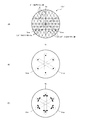
- FIG. 3A is a view of the first diffraction grating 131 ′ viewed from the direction along the optical axis
- FIG. 3B is a diagram showing three pairs of ⁇ first-order diffracted lights generated by the first diffraction grating 131 ′.
- Is a diagram showing three pairs of condensing points formed on the pupil conjugate plane 6A ′
- FIG. 3C is a diagram showing the polarization direction of the light transmitted through the half-wave plate.
- 4 is a diagram illustrating a liquid crystal element 63.
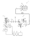
- FIG. 1 is a configuration diagram of the structured illumination microscope apparatus 1 of the present embodiment.
- the structured illumination microscope apparatus 1 includes a laser unit 100, an optical fiber 11, an illumination optical system 10, an imaging optical system 30, a first image sensor 351, and a second image sensor 352.
- a control device 39, an image storage / arithmetic device 40, and an image display device 45 are provided.
- the illumination optical system 10 is an epi-illumination type and illuminates the specimen 5 via the first dichroic mirror 7 and the objective lens 6 of the imaging optical system 30.
- the laser unit 100 includes a first laser light source 101, a second laser light source 102, shutters 103 and 104, a mirror 105, a dichroic mirror 106, a lens 107, and the like.
- Each of the first laser light source 101 and the second laser light source 102 is a coherent light source, and the emission wavelengths thereof are different from each other.
- the wavelength ⁇ 1 of the first laser light source 101 is longer than the wavelength ⁇ 2 of the second laser light source 102 ( ⁇ 1> ⁇ 2).
- the laser light having the wavelength ⁇ 1 emitted from the first laser light source 101 enters the dichroic mirror 106 through the shutter 103 and the mirror 105, the laser light is reflected by the dichroic mirror 106.
- the laser beam having the wavelength ⁇ 2 emitted from the second laser light source 102 enters the beam splitter 106 via the shutter 104, the laser beam is transmitted through the dichroic mirror 106 and integrated with the laser beam having the wavelength ⁇ 1.
- the optical fiber 11 is, for example, a multimode optical fiber. If such a multimode optical fiber is used, the temporal coherency of laser light can be reduced.
- the illumination optical system 10 includes a collector lens 12, a dichroic mirror 55, a mirror 56, a first polarizing plate 231, a second polarizing plate 232, a first diffractive optical element (first diffraction grating) 131, A two-diffractive optical element (second diffraction grating) 132, a dichroic mirror 57, a mirror 58, a condenser lens 16, a zero-order light cut mask 14, a lens 25, a field stop 26, a field lens 27,
- the excitation filter 28, the first dichroic mirror 7, and the objective lens 6 are disposed.
- the laser light emitted from the emission end (point light source) of the optical fiber 11 is converted into a parallel light beam by the collector lens 12 and then enters the dichroic mirror 55.
- the laser light incident on the dichroic mirror 55 the laser light having the wavelength ⁇ 1 is transmitted through the dichroic mirror 55 and incident on the first diffraction grating 131 via the first polarizing plate 231. Is done. These diffracted light beams enter the dichroic mirror 57 via the mirror 58 and are reflected by the condenser lens 16 when reflected by the dichroic mirror 57.
- the laser light incident on the dichroic mirror 55 the laser light having the wavelength ⁇ 2 reflects the dichroic mirror 55 and enters the second diffraction grating 132 via the mirror 56 and the second polarizing plate 232. Is branched into diffracted light beams. These diffracted light beams pass through the dichroic mirror 57 and are collected by the condenser lens 16.
- the first diffraction grating 131 is a one-way diffraction grating having a periodic structure (grating pitch) in a predetermined direction (direction perpendicular to the grating line) in a plane perpendicular to the optical axis of the illumination optical system 10.
- the first polarizing plate 231 is a polarizing plate that adjusts the polarization direction of the laser light incident on the first diffraction grating 131 in the same direction as the grating line of the first diffraction grating 131. Further, the distance from the arrangement surface of the first diffraction grating 131 to the condenser lens 16 corresponds to the focal length of the condenser lens 16.
- the pupil conjugate plane 6A ' is the focal position (rear focal position) of the lens 16, and the lens 27 and the lens 25 with respect to a pupil 6A (a position where ⁇ first-order diffracted light is condensed) of the objective lens 6 described later.
- These positions are concepts that include positions determined by a person skilled in the art in consideration of design requirements such as aberration and vignetting of the objective lens 6 and the lenses 27 and 25.
- the direction of translational movement may be a direction having a component in the same direction as the branching direction even if it does not coincide with the branching direction.
- the first diffraction grating 131 and the first polarizing plate 231 can be rotated around the optical axis at a pitch of 120 ° by the first rotation mechanism 151B.
- an electric motor or the like can be applied as the first rotation mechanism 151B.
- the first diffraction grating 131 rotates, the direction of the interference fringes (described later) of the wavelength ⁇ 1 switches between 0 °, 120 °, and 240 °, and the first polarizing plate 231 rotates together with the first diffraction grating 131.
- the relationship between the branching direction of the diffracted light beam with wavelength ⁇ 1 and the polarization direction is maintained, and as a result, the diffracted light beam contributing to the interference fringes with wavelength ⁇ 1 is maintained as s-polarized light.
- the direction of translational movement by the first translation mechanism 151A is the same component as that in the branching direction when the rotation position of the first diffraction grating 131 is 0 °, 120 °, or 240 °. It is assumed that the predetermined direction is set. However, in this case, since the relationship between the translational movement amount and the phase shift amount varies depending on the rotation position of the first diffraction grating 131, the translation is performed so that the phase shift amount becomes equal regardless of the rotation position of the first diffraction grating 131. It is assumed that the movement pitch is set for each rotation position of the first diffraction grating 131.
- the second diffraction grating 132 is a one-way diffraction grating having a periodic structure (grating pitch) in a predetermined one direction (direction perpendicular to the grating line) in a plane perpendicular to the optical axis of the illumination optical system 10.
- the second polarizing plate 232 is a polarizing plate that adjusts the polarization direction of the laser light incident on the second diffraction grating 132 in the same direction as the grating line of the second diffraction grating 132. Further, the distance from the arrangement surface of the second diffraction grating 132 to the condenser lens 16 corresponds to the focal length of the condenser lens 16.
- the direction of translational movement may be a direction having a component in the same direction as the branching direction even if it does not coincide with the branching direction.
- the second diffraction grating 132 and the second polarizing plate 232 can be rotated around the optical axis at a pitch of 120 ° by the second rotation mechanism 152B.
- the structure similar to the above-mentioned 1st rotation mechanism 151B is applicable.
- the direction of translation by the second translation mechanism 152A is the same component as that of the branching direction when the second diffraction grating 132 is rotated at 0 °, 120 °, or 240 °. It is assumed that the predetermined direction is set. However, in this case, since the relationship between the translational movement amount and the phase shift amount varies depending on the rotation position of the second diffraction grating 132, the translation is performed so that the phase shift amount becomes equal regardless of the rotation position of the second diffraction grating 132. The movement pitch is set for each rotation position of the second diffraction grating 132.
- the relationship between the structural period (grating pitch) of the first diffraction grating 131 and the structural period (grating pitch) of the second diffraction grating 132 is the ⁇ first-order diffraction generated in the first diffraction grating 131.
- the diffraction angle of the light beam and the diffraction angle of the ⁇ first-order diffracted light beam generated by the second diffraction grating 132 are set to be equal.
- the grating pitch of the second diffraction grating 132 is the first diffraction grating. It is set finer by a fixed amount than the lattice pitch of the lattice 131.
- the arrangement pattern (arrangement interval) of the condensing point pairs (condensing point pair of wavelength ⁇ 1) formed on the pupil conjugate plane 6A ′ by the ⁇ first-order diffracted light beams generated by the first diffraction grating 131, and the first The arrangement pattern (arrangement interval) of the condensing point pair (condensing point pair of wavelength ⁇ 2) formed on the pupil conjugate plane 6A ′ by the ⁇ first-order diffracted light beams generated by the two diffraction gratings 132 is the same (however, the wavelength (The arrangement direction of the collection point pair of ⁇ 1 depends on the rotation position of the first diffraction grating 131, and the arrangement direction of the collection point pair of wavelength ⁇ 2 depends on the rotation position of the second diffraction grating 132.) .
- the diffracted light beams of the respective orders from the first diffraction grating 131 or the second diffraction grating 132 toward the pupil conjugate plane 6A ′ enter the 0th-order light cut mask 14 arranged in the vicinity of the pupil conjugate plane 6A ′.
- ⁇ 1st-order diffracted light beams pass through the 0th-order light cut mask 14, and other diffracted light beams are cut by the 0th-order light cut mask 14.
- the 0th-order light cut mask 14 is formed by forming a plurality of openings or transmission parts on a mask substrate.
- the positions of the openings or transmission parts on the substrate are ⁇ 1st order diffracted light on the pupil conjugate plane. Corresponds to the incident position.
- the ⁇ 1st-order diffracted light beam of wavelength ⁇ 1 that has passed through the 0th-order light cut mask 14 forms a surface (image of the first diffraction grating 131) conjugate with the first diffraction grating 131 near the field stop 26 by the lens 25,
- the ⁇ 1st-order diffracted light beam of wavelength ⁇ 2 that has passed through the 0th-order light cut mask 14 forms a plane (image of the second diffraction grating 132) conjugate with the second diffraction grating 132 in the vicinity of the field stop 26 by the lens 25.
- One and the other of the ⁇ first-order diffracted light beams incident on the field stop 26 are converted into parallel light by the field lens 27, and after passing through the excitation filter 28, reflected by the first dichroic mirror 7, and the pupil plane 6 ⁇ / b> A of the objective lens 6.
- the light is condensed at positions symmetrical to each other with respect to the optical axis.
- the condensing points formed on the pupil plane 6A include a condensing point pair having a wavelength ⁇ 1 and a condensing point pair having a wavelength ⁇ 2.
- the arrangement pattern (arrangement interval) of the condensing point pair of wavelength ⁇ 2 on the pupil plane 6A is the same (however, the arrangement direction of the condensing point pair of wavelength ⁇ 1 is the rotation of the first diffraction grating 131) Depending on the position, the direction in which the pair of condensing points of wavelength ⁇ 2 is arranged depends on the rotational position of the second diffraction grating 132).
- the interference fringes formed on the sample 5 include an interference fringe having a wavelength ⁇ 1 and an interference fringe having a wavelength ⁇ 2. These interference fringes are used as structured illumination light for spatially modulating the specimen 5.
- the periodic structure of the interference fringes and the periodic structure (of the fluorescent region) of the specimen 5 When the specimen 5 is illuminated with such interference fringes, the periodic structure of the interference fringes and the periodic structure (of the fluorescent region) of the specimen 5 generate moire fringes. In the moire fringes, the high-frequency structure of the specimen 5 is generated. Is shifted to a lower frequency side than the original frequency, the light generated according to this structure travels toward the objective lens 6 at an angle smaller than the original angle. Therefore, when the specimen 5 is illuminated by the interference fringes, even the high-frequency structural information of the specimen 5 is transmitted by the objective lens 6 and a super-resolution effect is obtained.
- the super-resolution effect is a ratio between the resolution R of the structured illumination microscope apparatus 1 when the specimen 5 is not modulated and the resolution (R + K) of the structured illumination microscope apparatus 1 when the specimen 5 is modulated. (R + K) / R.
- the super-resolution effect (R ( ⁇ ) + K (P)) / R ( ⁇ ) has a wavelength ⁇ 1. , ⁇ 2 is not common.
- the arrangement pattern of the condensing point pair of the wavelength ⁇ 1 on the pupil plane 6A and the arrangement pattern of the condensing point pair of the wavelength ⁇ 2 on the pupil plane 6A are the same.
- An appropriate difference was given between the grating pitch P1 of the first diffraction grating 131 and the grating pitch P2 of the second diffraction grating 132.
- the grating pitch P1 of the first diffraction grating 131 and the grating pitch P2 of the second diffraction grating 132 can be set independently, even if the difference between the wavelength ⁇ 1 and the wavelength ⁇ 2 is large, the wavelength Both the condensing point pair of ⁇ 1 and the condensing point pair of wavelength ⁇ 2 are accommodated in the pupil plane 6A, and both the interference fringes of wavelength ⁇ 1 and the interference fringes of wavelength ⁇ 2 can be generated reliably. Therefore, it is possible to reliably obtain both the super-resolution effect due to the interference fringes with the wavelength ⁇ 1 and the super-resolution effect due to the interference fringes with the wavelength ⁇ 2.
- the specimen 5 is, for example, a culture solution dropped on a parallel plate-like glass surface, and in the vicinity of the glass interface in the culture solution, a fluorescent cell (a cell stained with a fluorescent dye) ) Exists.
- a fluorescent cell a cell stained with a fluorescent dye
- both the first fluorescent region excited by light of wavelength ⁇ 1 and the second fluorescent region excited by light of wavelength ⁇ 2 are expressed.
- fluorescence of wavelength ⁇ 1 ' is generated according to light of wavelength ⁇ 1
- fluorescence of wavelength ⁇ 2' is generated according to light of wavelength ⁇ 2.
- Fluorescence generated in the specimen 5 enters the imaging optical system 30.
- an objective lens 6, a first dichroic mirror 7, a barrier filter 31, a second objective lens 32, and a second dichroic mirror 35 are arranged in this order from the sample 5 side.
- the fluorescence having the wavelength ⁇ 1 ' reflects the second dichroic mirror 35, and the fluorescence having the wavelength ⁇ 2' passes through the second dichroic mirror 35.
- the fluorescence having the wavelength ⁇ 1 ′ reflected from the second dichroic mirror 35 forms a modulated image of the first fluorescence region on the imaging surface 361 of the first imaging device 351, and transmits the fluorescence having the wavelength ⁇ 2 ′ transmitted through the second dichroic mirror 35. Forms a modulated image of the second fluorescent region on the imaging surface 362 of the second imaging element 352.
- Each of the first image sensor 351 and the second image sensor 352 is a charge storage type two-dimensional image sensor such as a CCD or a CMOS.
- the first image sensor 351 acquires the first modulated image by capturing the modulated image of the first fluorescent region and sends it to the control device 39, and the second image sensor 352 captures the modulated image of the second fluorescent region. As a result, the second modulated image is acquired and sent to the control device 39.
- the control device 39 includes the first laser light source 101, the second laser light source 102, the shutters 103 and 104, the first translation mechanism 151A, the second translation mechanism 152A, the first rotation mechanism 151B, the second rotation mechanism 152B, and the first.
- a series of first modulated images and a series of second modulated images are acquired by controlling each of the image sensor 351 and the second image sensor 352, the series of first modulated images and series of second modulated images are stored in the image. -It gives to the arithmetic unit 40.
- the control device 39 can control the irradiation timing of the laser light having the wavelength ⁇ 1 on the sample 5 by controlling the combination of the on / off timing of the first laser light source 101 and the opening / closing timing of the shutter 103. .
- control device 39 can control the irradiation timing of the laser beam having the wavelength ⁇ 2 on the sample 5 by controlling the combination of the on / off timing of the second laser light source 102 and the opening / closing timing of the shutter 104. .
- the shutters 103 and 104 are composed of, for example, an acousto-optic device such as AOTF
- the irradiation timing of the laser light with the wavelengths ⁇ 1 and ⁇ 2 on the sample 5 can be controlled by simply controlling the AOTF. it can.
- control device 39 can control the frame period of the first image sensor 351 by controlling the charge accumulation timing and the charge read timing of the first image sensor 351.
- control device 39 can control the frame period of the second image sensor 352 by controlling the charge accumulation timing and the charge read timing of the second image sensor 352.
- the frame period refers to the time from the start of capturing one image by the image sensor to the start of capturing the next image.
- the control device 39 also includes a charge accumulation period within the frame period of the first image sensor 351 and an open period within the frame period of a mechanical shutter (not shown) disposed between the first image sensor 351 and the sample 5. By controlling this combination, the exposure time (fluorescence light reception time) within the frame period of the first image sensor 351 can be controlled.
- the control device 39 also includes a charge accumulation period within the frame period of the second image sensor 352, and an open period within the frame period of the mechanical shutter (not shown) disposed between the second image sensor 352 and the sample 5. By controlling the combination, the exposure time (fluorescence light receiving time) within the frame period of the second image sensor 352 can be controlled.
- the image storage / arithmetic unit 40 performs a known demodulation calculation on the series of first modulated images given from the control unit 39 to generate a first demodulated image (first super-resolution image), and also the control unit A known demodulation operation is performed on the series of second modulated images given from 39 to generate a second demodulated image (second super-resolution image).
- a known demodulation calculation for example, a method disclosed in US81115806 can be used.
- the first super-resolution image and the second super-resolution image are stored in an internal memory (not shown) of the image storage / arithmetic device 40 and sent to the image display device 45.
- the control device 39 acquires a series of first modulated images necessary for the demodulation calculation and a series of second modulated images necessary for the demodulation calculation by the following procedures (0) to (6).
- the control device 39 sets the wavelength of the laser light applied to the specimen 5 to both ⁇ 1 and ⁇ 2.
- the control device 39 sets the rotation positions of the first diffraction grating 131 and the second diffraction grating 132 to 0 ° via the first rotation mechanism 151B and the second rotation mechanism 152B, thereby causing interference fringes. Is set to 0 °.
- the control device 39 starts translational movement of the first diffraction grating 131 and the second diffraction grating 132 via the first translation mechanism 151A and the second translation mechanism 152A.
- the control device 39 irradiates the sample 5 with laser light during the translational movement of the first diffraction grating 131 and the second diffraction grating 132, and exposes both the first imaging element 351 and the second imaging element 352. (Imaging) is repeated over a plurality of sheets.
- the control device 39 sets the pitch of the translational movement of the first diffraction grating 131 in accordance with the frame period of the first imaging element 351 during the imaging period of the plurality of sheets by the first imaging element 351 and the second imaging element 352. And the pitch of the translational movement of the second diffraction grating 132 is set to a pitch corresponding to the frame period of the second image sensor 352, whereby the phase difference of interference fringes between adjacent images of a series of first modulated images is set. Is set to a predetermined value ⁇ less than 2 ⁇ , and the phase difference of interference fringes between adjacent images of a series of second modulated images is set to a predetermined value ⁇ less than 2 ⁇ .
- the control device 39 sets the rotation positions of the first diffraction grating 131 and the second diffraction grating 132 to 120 ° via the first rotation mechanism 151B and the second rotation mechanism 152B, and performs the procedure in that state. (2) to (4) are executed.
- the control device 39 sets the rotation positions of the first diffraction grating 131 and the second diffraction grating 132 to 240 ° via the first rotation mechanism 151B and the second rotation mechanism 152B, and performs the procedure in that state. (2) to (4) are executed.
- the control device 39 determines that the direction of the interference fringes is 0 ° and the phase of the interference fringes is shifted by ⁇ , and the direction of the interference fringes. Is 120 ° and the phase of the interference fringes is shifted by ⁇ and at least three first modulated images, and the direction of the interference fringes is 240 ° and the phase of the interference fringes is shifted by ⁇ .
- the modulated image is acquired in order. These at least nine first modulated images are a series of first modulated images necessary for generating the first super-resolution image.
- the control device 39 obtains at least three second modulated images in which the direction of the interference fringes is 0 ° and the phase of the interference fringes is shifted by ⁇ . , At least three second modulated images with the interference fringe direction being 120 ° and the interference fringe phase shifted by ⁇ , and the interference fringe direction being 240 ° and the interference fringe phase being shifted by ⁇ Three second modulated images are acquired in order. These at least nine second modulated images are a series of second modulated images necessary for generating the second super-resolution image.
- the structured illumination microscope apparatus 1 includes each of the two light branching portions (131, 132) and the two light branching portions (131, 132) that individually split two kinds of light beams having different wavelengths. And an optical system (10) for causing the plurality of branched components generated in step (b) to interfere on the specimen.
- the light branching portions (131, 132) are prepared for each wavelength, it is possible to set the branching angle of the light flux for each wavelength, so that the difference in the branching angle due to the difference in wavelength can be suppressed. .
- the configuration of the structured illumination microscope apparatus 1 according to the present embodiment is advantageous in expanding the wavelength range used.
- each of the two light branching portions (131, 132) is a diffractive optical element, and the structural period is mutually between the two light branching portions (131, 132). Unlikely, the relationship of the structural period between the two optical branching portions is set so that the super-resolution effect is equal between wavelengths.
- a plurality of diffraction components generated in each of the two light branching portions (131, 132) are located at different positions on the pupil (6A) of the objective lens (6). These diffraction components interfere with each other on the object side of the objective lens by focusing on the object lens, and the relationship between the structural periods between the two optical branching portions (131, 132) is that a plurality of diffraction components are on the pupil (6A).
- the arrangement pattern of a plurality of condensing points to be formed is set to be equal between wavelengths.
- the super-resolution effect of the structured illumination microscope apparatus 1 of the present embodiment is unchanged regardless of the wavelength used.
- the two light branching portions (131, 132) are individually arranged on the non-common optical paths of the two types of light beams.
- the detection optical system (30) detects the image of the sample (5) for each wavelength.
- the sample (5) is simultaneously illuminated (excited) with two types of use wavelengths, and two types of images formed according to the two types of use wavelengths are simultaneously displayed. It is possible to detect.
- the two polarizing plates (231 and 232) are individually arranged on the non-common optical paths of the two types of light beams.
- one characteristic of the two polarizing plates (231, 232) is made optimal for one of two types of light beams having different wavelengths, and the two polarizing plates
- the other characteristic of (231, 232) can be made optimum for the other of the two types of light beams having different wavelengths.
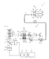
- FIG. 2 is a configuration diagram of the structured illumination microscope apparatus 1 of the present embodiment. Since the present embodiment is a modification of the first embodiment, only differences from the first embodiment will be described here.
- a first diffraction grating 131 ′ and a second diffraction grating 132 ′ that branch light in three directions are used instead of the first diffraction grating 131 and the second diffraction grating 132 that branch light in one direction.
- a light beam selecting member 18 for selecting a diffracted light beam in a necessary direction is disposed.
- the arrangement location of the first diffraction grating 131 ′ is the same as the arrangement location of the first diffraction grating 131 of the first embodiment
- the arrangement location of the second diffraction grating 132 ′ is the second diffraction grating of the first embodiment.
- the arrangement location of the grating 132 is the same, and the arrangement location of the light beam selection member 18 is in the vicinity of the pupil conjugate plane 6A ′.
- the postures of the first diffraction grating 131 ′ and the second diffraction grating 132 ′ are fixed, and the light beam selection member 18 can be rotated around the optical axis at a pitch of 120 ° by the rotation mechanism 18A. is there.
- the polarizing plate 23 is disposed between the collector lens 12 and the dichroic mirror 55 (a common optical path of the laser light having the wavelength ⁇ 1 and the laser light having the wavelength ⁇ 2).
- Each arrangement position of the liquid crystal element 62 is in the vicinity of the pupil conjugate plane 6A ′.
- one liquid crystal element (third liquid crystal element 63) is arranged instead of the first translation mechanism 151A and the second translation mechanism 152A.
- the arrangement position of the third liquid crystal element 63 is in the vicinity of the pupil conjugate plane 6A '.
- the first diffraction grating 131 ′ has a periodic structure in each of a 0 ° direction V 0 , a 120 ° direction V 120 , and a 240 ° direction V 240 ,
- the period (grating pitch) of the periodic structures (grating lines) in each direction is common.
- the plurality of grid lines arranged toward the direction V 0 which is a grid line for branching the incident light beam in the direction V 0 which 0 °
- the plurality of grid lines arranged toward the direction V 120 of the 120 ° a grid line for branching the incident light beam toward the direction V 120 of 120 °
- the lattice line for branching the incident light beam in the 0 ° direction V 0 is referred to as “0 ° branching lattice line”
- the lattice line for branching the incident light beam in the 120 ° direction V 120 is referred to as “120”.
- the grid line for branching the incident light beam in the 240 ° direction V 240 is referred to as a “240 ° branch grid line”.
- the first diffraction grating 131 ′ simultaneously branches the incident light beam in each of the 0 ° direction V 0 , the 120 ° direction V 120 , and the 240 ° direction V 240 to generate three pairs of ⁇ first-order diffracted light beams. Generate at the same time. These three pairs of ⁇ first-order diffracted light beams form three pairs of condensing points on the pupil conjugate plane 6A ′ as shown in FIG.
- the pair of condensing points is formed by a ⁇ first-order diffracted light beam branched in a 120 ° direction V 120 , and the pair of condensing points arranged in a 240 ° direction V 240 has a 240 ° direction. ⁇ branched into V 240 1 in which order diffracted light flux is formed.
- the periodic structure of the first diffraction grating 131 ′ is a concentration-type periodic structure formed using density (transmittance) or a phase-type periodic structure formed using steps (phase difference).
- the phase difference type periodic structure is preferable in that the diffraction efficiency of the + 1st order diffracted light is higher.
- the structure of the second diffraction grating 132 ′ is the same as the structure of the first diffraction grating 131 ′, and the direction of the grating line of the second diffraction grating 132 ′ is the same as that of the first diffraction grating 131 ′. Corresponding direction) is set.
- the grating pitch of the second diffraction grating 132 ′ is different from the grating pitch of the first diffraction grating 131 ′, and the grating pitch of the second diffraction grating 132 ′ and the grating pitch of the first diffraction grating 131 ′ are different.
- the relationship is the same as the relationship in the first embodiment (the relationship between the grating pitch of the second diffraction grating 132 and the grating pitch of the first diffraction grating 131).
- the axial direction of the polarizing plate 23 is set so that the polarization direction of the incident light beam with respect to the first diffraction grating 131 ′ and the second diffraction grating 132 ′ is adjusted in the same direction as the 0 ° branching grating line. .
- the first liquid crystal element 61 is an element that can control the refractive index anisotropy by electrically controlling the orientation of the liquid crystal. Therefore, when the first liquid crystal element 61 is turned on by the drive circuit 61A, the first liquid crystal element 61 has the wavelengths ⁇ 1 and ⁇ 2. Acts as a half-wave plate for the incident light beam and is turned off by the drive circuit 61A, it is parallel to the incident light beam of wavelengths ⁇ 1 and ⁇ 2 (refractive index anisotropy 0, refractive index isotropic).
- the direction of the fast axis of the first liquid crystal element 61 in the on state is set to a direction rotated by ⁇ 30 ° when the clockwise direction is + with respect to the axial direction of the polarizing plate 23. .
- the structure of the second liquid crystal element 62 is the same as that of the first liquid crystal element 61.
- a half-wave plate with respect to incident light of wavelengths ⁇ 1 and ⁇ 2 is used.
- it is turned off by the drive circuit 62A it acts as a parallel plate for incident light of wavelengths ⁇ 1 and ⁇ 2.
- the direction of the fast axis of the second liquid crystal element 62 in the on state is different from the direction of the fast axis of the first liquid crystal element 61, and +30 with respect to the axial direction of the polarizing plate 23. It is set in the direction rotated by °.
- ⁇ first-order diffracted light beams branched in a direction of 0 ° V 0 (a pair of condensing points arranged in a direction of 0 ° V 0 ) and ⁇ first-order diffraction beams branched in a direction of V 120 of 120 ° a light beam (a pair of converging point arranged in the direction V 120 of 120 °)
- 240 ° ⁇ 1-order diffracted light beam (240 ° a pair of current arranged in a direction V 240 of the branched direction V 240 of Each polarization state with respect to the light spot) is set to S-polarized light when the specimen 5 is irradiated. That is, the polarization direction of each light after passing through the half-wave plate is set to a direction as shown in FIG.
- the direction of the fast axis of the 1/2-wavelength plate (first liquid crystal element 61) is passed through a 1/2-wavelength plate
- the polarization direction of the light after that ( ⁇ 60 ° with respect to the grid line for 0 ° branching) and the polarization direction of the light before passing through the half-wave plate are 2 It is necessary to set the direction equally divided, that is, the direction rotated by ⁇ 30 ° with respect to the axial direction of the polarizing plate 23 ( ⁇ 30 ° with respect to the grid line for 0 ° branching).
- the fast axis direction of the half-wave plate (second liquid crystal element 62) is after passing through the half-wave plate.
- the light polarization direction (+ 60 ° with respect to the 0 ° branching grid line) and the light polarization direction before passing through the half-wave plate are divided into two equal parts.
- Direction that is, a direction rotated by + 30 ° with respect to the axial direction of the polarizing plate 23 (+ 30 ° with respect to the grid line for 0 ° branching).
- the second liquid crystal element 62 is In the case where the polarization direction of those ⁇ 1st order diffracted light beams that have passed is the same direction as the 0 ° branching grating line and the ⁇ 1st order diffracted light beams branched in the direction 120 of 120 ° are used, the first liquid crystal element By turning on only 61, the polarization directions of the ⁇ first-order diffracted light beams that have passed through the second liquid crystal element 62 are set to the same direction as the grid lines for 120 ° branching, and branched into a direction V 240 of 240 °.
- the polarization direction of light after passing through the half-wave plate and the polarization direction of light before passing through the half-wave plate ( The angle formed by the axial direction of the polarizing plate 23 is assumed to be an acute angle, but may be an obtuse angle (the phase is only shifted by ⁇ , and it remains S-polarized light).
- the third liquid crystal element 63 acts as a phase plate for the incident light beams of wavelengths ⁇ 1 and ⁇ 2, and sets the phase delay amount of the incident light beam for each region in accordance with a signal given from the drive circuit 63A. It is possible.
- the liquid crystal element 63 there are at least a region A and a region A ′ shown in FIG.
- One region A is one incident region of ⁇ first-order diffracted light beams branched in the direction of 0 °, one incident region of ⁇ first-order diffracted light beams branched in the direction of 120 °, and branched in the direction of 240 °. It is a set with one incident region of the ⁇ first-order diffracted light flux.
- the other region A ′ includes the other incident region of the ⁇ 1st-order diffracted light beam branched in the 0 ° direction, the other incident region of the ⁇ 1st-order diffracted light beam branched in the 120 ° direction, and the 240 ° direction. It is a set with the other incident area of the branched ⁇ first-order diffracted light beams.
- the drive circuit 63A gives a difference (phase delay amount difference) between the phase delay amount in the region A and the phase delay amount in the region A ′, the phase difference between the ⁇ first-order diffracted light beams branched in the 0 ° direction. And a phase difference is given between ⁇ 1st order diffracted light beams branched in the direction of 120 °, and a phase difference is given between ⁇ 1st order diffracted light beams branched in the direction of 240 °.
- the drive circuit 63A shifts the phase delay amount difference between the regions A and A ′, the phase difference of the ⁇ 1st-order diffracted light beams branched in the 0 ° direction is shifted and branched in the 120 ° direction.
- the phase difference of the ⁇ 1st order diffracted light beam is shifted, and the phase difference of the ⁇ 1st order diffracted light beam branched in the direction of 240 ° is shifted.
- the phase of the interference fringes in the direction of 0 ° is shifted
- the phase of the interference fringes in the direction of 120 ° is shifted
- the phase of the interference fringes in the direction of 240 ° is shifted.
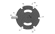
- the opening pattern of the light beam selection member 18 includes a first opening portion 19 and a second opening portion that individually allow one and the other of the ⁇ first-order diffracted light beams branched in a certain direction to pass therethrough. 20, and the lengths of the first opening 19 and the second opening 20 around the optical axis are set such that linearly polarized ⁇ first-order diffracted light beams can pass therethrough. . Therefore, each shape of the 1st opening part 19 and the 2nd opening part 20 is a shape close
- the light beam selection member 18 can be rotated around the optical axis at a pitch of 120 ° by the rotation mechanism 18A.
- the rotation position of the light beam selection member 18 is set to 120 °, of ⁇ 1st order diffracted light beams branched in the directions of 0 °, 120 °, and 240 °, ⁇ 1 branched in the direction of 120 °. Since only the next diffracted light passes through the light beam selection member 18, the direction of the interference fringes formed on the sample 5 is 120 °.
- the rotational position of the light beam selection member 18 is set to 240 °, out of ⁇ first-order diffracted light beams branched in the directions of 0 °, 120 °, and 240 °, ⁇ 1 branched in the direction of 240 °. Since only the next-order diffracted light passes through the light beam selection member 18, the direction of the interference fringes formed on the sample 5 is a direction of 240 °.
- a plurality of (six in the example shown in FIG. 5) notches 21 are formed on the outer peripheral portion of the light beam selecting member 18 as shown in FIG.
- a sensor 22 for detecting the presence or absence of these notches 21 is disposed at a position directly opposite to the locus.
- the sensor 22 is composed of a photo interrupter or the like.
- the detection signal of the sensor 22 can be used as a signal (angle signal) indicating the rotational position of the light beam selection member 18.
- the control device 39 acquires a series of first modulated images necessary for the demodulation calculation and a series of second modulated images necessary for the demodulation calculation by the following procedures (0) to (6).
- the control device 39 sets the wavelength of the laser light applied to the specimen 5 to both ⁇ 1 and ⁇ 2.
- the control device 39 sets the direction of the interference fringes to the direction of 0 ° by setting the rotation position of the light beam selection member 18 to the direction of 0 ° via the rotation mechanism 18A. Further, the control device 39 sets the ⁇ first-order diffracted light flux contributing to the interference fringes to s-polarized light by turning off both of the liquid crystal elements 61 and 62 via the drive circuits 61A and 62A.
- the control device 39 starts shifting the phase delay amount difference between the regions A and A ′ of the liquid crystal element 63 via the drive circuit 63A.
- the control device 39 irradiates the specimen 5 with laser light during the shift of the phase delay amount difference, and exposes (images) both the first image sensor 351 and the second image sensor 352 over a plurality of sheets. And repeat. Note that the frame period of the first image sensor 351 and the frame period of the second image sensor 352 are set in common.
- the control device 39 sets the shift pitch of the phase delay amount difference to the frame period of the first image sensor 351 and the second image sensor 352 during a plurality of image capturing periods by the first image sensor 351 and the second image sensor 352.
- the phase difference of interference fringes between adjacent images of a series of first modulated images is set to a predetermined value ⁇ less than 2 ⁇
- the interference fringes between adjacent images of a series of second modulated images Is set to a predetermined value ⁇ of less than 2 ⁇ .
- the control device 39 sets the direction of the interference fringes to the direction of 120 ° by setting the rotation position of the light beam selection member 18 to the direction of 120 ° via the rotation mechanism 18A. Further, the control device 39 turns on only the former of the liquid crystal elements 61 and 62 via the drive circuits 61A and 62A, thereby setting the ⁇ first-order diffracted light flux contributing to the interference fringes to s-polarized light. In this state, the control device 39 executes steps (2) to (4).
- the control device 39 sets the direction of the interference fringes to the direction of 240 ° by setting the rotation position of the light beam selection member 18 to the direction of 240 ° via the rotation mechanism 18A. Further, the control device 39 sets only the latter of the liquid crystal elements 61 and 62 via the drive circuits 61A and 62A, thereby setting the ⁇ 1st-order diffracted light beam contributing to the interference fringes to s-polarized light. In this state, the control device 39 executes steps (2) to (4).
- the control device 39 determines that the direction of the interference fringes is 0 ° and the phase of the interference fringes is shifted by ⁇ , and the direction of the interference fringes. Is 120 ° and the phase of the interference fringes is shifted by ⁇ and at least three first modulated images, and the direction of the interference fringes is 240 ° and the phase of the interference fringes is shifted by ⁇ .
- the modulated image is acquired in order. These at least nine first modulated images are a series of first modulated images necessary for generating the first super-resolution image.
- the control device 39 obtains at least three second modulated images in which the direction of the interference fringes is 0 ° and the phase of the interference fringes is shifted by ⁇ . , At least three second modulated images with the interference fringe direction being 120 ° and the interference fringe phase shifted by ⁇ , and the interference fringe direction being 240 ° and the interference fringe phase being shifted by ⁇ Three second modulated images are acquired in order. These at least nine second modulated images are a series of second modulated images necessary for generating the second super-resolution image.
- the method of switching the direction of the interference fringes, the method of shifting the phase of the interference fringes, and the method of adjusting the polarization direction of the diffracted light beam contributing to the interference fringes are the first.
- the other points are the same as those of the structured illumination microscope apparatus 1 of the first embodiment.
- the structured illumination microscope apparatus 1 of the present embodiment can obtain a super-resolution effect at each of the two used wavelengths having a large wavelength difference, It is possible to share the image effect between wavelengths.
- FIG. 6 is a configuration diagram of the structured illumination microscope apparatus 1 of the present embodiment. Since the present embodiment is a modification of the first embodiment, only differences from the first embodiment will be described here.
- the first diffraction grating 131 ′′ acting only on the light of wavelength ⁇ 1 and the light of wavelength ⁇ 2 are used.
- Both the second diffraction grating 132 "acting only on the two laser beams are arranged in the common optical path of the two laser beams.
- the dichroic mirrors 55 and 57 and the mirrors 56 and 58 are omitted, and one polarizing plate is used for adjusting the polarization direction of the laser light having the wavelength ⁇ 1 and adjusting the polarization direction of the laser light having the wavelength ⁇ 2. 23 is also used.
- the location of the first diffraction grating 131 ′′ and the location of the second diffraction grating 132 are close to each other, and the distance from the location of both to the condenser lens 16 is equal to the focal length of the condenser lens 16.
- the widths of the first diffraction grating 131 ′′ and the second diffraction grating 132 ′′ in the optical axis direction are sufficiently small and fall within the focal depth of the condenser lens 16.
- first diffraction grating 131 ′′ and the second diffraction grating 132 ′′ are fixed to each other through an adhesive layer in a posture in which the grating lines are directed in the same direction, and the translational movement of the first diffraction grating 131 ′′
- One translation mechanism 15A is also used for translation of the second diffraction grating 132 ′′
- one rotation mechanism 15B is also used for rotation of the first diffraction grating 131 ′′ and rotation of the second diffraction grating 132 ′′.
- the acquisition of the first modulated image and the acquisition of the second modulated image share one image sensor 35. For this reason, the second dichroic mirror 55 is omitted.
- two units including the excitation filter 28, the first dichroic mirror 7, and the barrier filter 31 are prepared.
- a unit switching mechanism for switching the unit to be arranged between the two units is provided.
- One of these two units is a unit suitable for use wavelength ⁇ 1 (unit for wavelength ⁇ 1), and the other is a unit suitable for use wavelength ⁇ 2 (for wavelength ⁇ 2).
- Unit The control device 39 switches the unit arranged in the optical path between the unit for wavelength ⁇ 1 and the unit for wavelength ⁇ 2 through this unit switching mechanism.
- the first diffraction grating 131 ′′ is a hologram diffraction grating made of a photopolymer or the like. As shown in FIG. 7, the hologram diffraction grating has different angles with respect to a substrate such as a monomer mixed with a photosensitive agent. By projecting a pair of coherent light (object light and reference light) simultaneously, the interference fringes are projected onto the substrate, and the structure corresponding to the interference fringe pattern is fixed (recorded) on the substrate. is there.
- the hologram diffraction grating is a type suitable as the diffraction grating of this embodiment. (Transmission type). Further, if the wavelength of the pair of coherent light and the angle between the pair of coherent light (angle ⁇ r of the reference light with respect to the object light) are appropriately set, the selected wavelength region (hologram diffraction) of the hologram diffraction grating is set. The wavelength range of light diffracted by the grating can be limited to a desired wavelength range.
- the wavelength of the pair of coherent light at the time of manufacturing the hologram diffraction grating is set to 405 nm and the angle of the pair of coherent light (angle ⁇ r of the reference light with respect to the object light) is set to 60 °
- FIG. 8 shows the relationship between the angle of a pair of coherent light (the angle ⁇ r of the reference light with respect to the object light), the angle width ⁇ of the used light beam, and the wavelength width ⁇ of the selected wavelength region of the used light beam. Is shown.
- the example shown in FIG. 8 is an example in which the wavelength of a pair of coherent light is set to 405 nm in order to set the center wavelength of the used wavelength to 405 nm, but also when these wavelengths are set to other values. It is considered that a relationship similar to the relationship shown in FIG.
- a hologram diffraction grating manufactured with coherent light having a wavelength ⁇ 1 is used as the first diffraction grating 131 ′′ of the present embodiment.
- the second diffraction grating 132 ′′ is a hologram diffraction grating similar to the first diffraction grating 131 ′′.
- the wavelength of coherent light used in the production of the second diffraction grating 132 ′′ is set to ⁇ 2.
- the first diffraction grating 131 ′′ has a function of selectively diffracting the incident light beam having the wavelength ⁇ 1
- the second diffraction grating 132 ′′ has a function of selectively diffracting the incident light beam of the wavelength ⁇ 2. Is done.
- the manufacturing conditions ( ⁇ r) other than the wavelength are shared between the first diffraction grating 131 ′′ and the second diffraction grating 132 ′′. Accordingly, the relationship between the grating pitch of the second diffraction grating 132 ′′ and the grating pitch of the first diffraction grating 131 ′′ is the same as that in the first embodiment (the grating pitch of the second diffraction grating 132 and the grating of the first diffraction grating 131). The relationship with the pitch).
- the control device 39 acquires a series of first modulated images and a series of second modulated images necessary for the demodulation operation by the following procedures (0) to (7).
- the control device 39 sets the wavelength of the laser light applied to the specimen 5 to ⁇ 1, and sets the unit set in the optical path to the unit for wavelength ⁇ 1.
- the control device 39 sets the rotation positions of the first diffraction grating 131 ′′ and the second diffraction grating 132 ′′ to 0 ° via the rotation mechanism 15B.
- the control device 39 starts the translational movement of the first diffraction grating 131 ′′ and the second diffraction grating 132 ′′ via the translation mechanism 15A.
- the control device 39 irradiates the sample 5 with laser light during translation of the first diffraction grating 131 ′′ and the second diffraction grating 132 ′′, and performs exposure (imaging) of the imaging device 35 over a plurality of sheets. And repeat.
- the control device 39 sets the pitch of the translational movement of the first diffraction grating 131 ′′ and the second diffraction grating 132 ′′ to a pitch corresponding to the frame period of the imaging element 35 during the imaging period of the plurality of sheets by the imaging element 35.
- the phase difference of the interference fringes between adjacent images of the series of modulated images acquired in the procedure (3) is set to a predetermined value ⁇ less than 2 ⁇ .
- the control device 39 sets the rotation positions of the first diffraction grating 131 ′′ and the second diffraction grating 132 ′′ to 120 ° via the rotation mechanism 15B, and in this state, performs steps (2) to (4). Execute.
- the control device 39 sets the rotation positions of the first diffraction grating 131 ′′ and the second diffraction grating 132 ′′ to 240 ° via the rotation mechanism 15B, and performs the procedures (2) to (4) in that state. Execute.
- the control device 39 sets the wavelength of the laser light applied to the sample 5 to ⁇ 2, and sets the unit to be set in the optical path to the unit for the wavelength ⁇ 2, and in this state, the procedures (1) to ( 6) is executed.
- the control device 39 determines that the direction of the interference fringes is 0 ° and the phase of the interference fringes is shifted by ⁇ , and the direction of the interference fringes. Is 120 ° and the phase of the interference fringes is shifted by ⁇ and at least three first modulated images, and the direction of the interference fringes is 240 ° and the phase of the interference fringes is shifted by ⁇ .
- the modulated image is acquired in order. These at least nine first modulated images are a series of first modulated images necessary for generating the first super-resolution image.
- the control device 39 causes the direction of the interference fringes to be 0 ° and the phase of the interference fringes to be shifted by ⁇ and the direction of the interference fringes to be 120. And at least three second modulated images whose phases of interference fringes are shifted by ⁇ , and at least three second modulated images whose directions of interference fringes are 240 ° and whose phases of interference fringes are shifted by ⁇ . And in order. These at least nine second modulated images are a series of second modulated images necessary for generating the second super-resolution image.
- the two light branch portions (131 ′′, 132 ′′) are arranged in the common optical path of the two types of light beams, and one of the two light branch portions is two types.
- the second embodiment has the wavelength selectivity for selectively branching one of the light beams, and the other of the two light branching portions has the wavelength selectivity for selectively branching the other of the two types of light beams.
- the other points are the same as those of the structured illumination microscope apparatus 1 of the first embodiment.
- the structured illumination microscope apparatus 1 of the present embodiment can obtain a super-resolution effect at each of the two used wavelengths having a large wavelength difference, It is possible to share the image effect between wavelengths.
- a rotatable diffraction grating is used to switch the direction of the interference fringes.
- the diffraction grating can be switched in accordance with the electrical signal. (Spatial light modulation element) or the like may be used.
- a translationally movable diffraction grating is used to shift the phase of the interference fringes, but the grating position can be shifted in accordance with an electrical signal.
- a diffraction grating spatial light modulation element or the like may be used.
- the rotatable light beam selection member is used to switch the direction of the interference fringes, but the light beam capable of switching the aperture pattern according to the electrical signal.
- a selection member liquid crystal element or the like may be used.
- the structured illumination microscope apparatus 1 of the second embodiment is the same as the structured illumination microscope apparatus 1 of the first embodiment in all of the interference fringe direction switching method, the interference fringe phase shift method, and the polarization direction adjustment method. However, it is also possible to realize a structured illumination microscope apparatus in which only a part is modified.
- the number of imaging elements is two in order to capture two modulated images having different wavelengths in parallel.
- the number of image sensors may be 1.
- the second dichroic mirror 35 and the image sensor 351 are omitted, and two units (cubes) including the excitation filter 28, the first dichroic mirror 7, and the barrier filter 31 are prepared, and the units arranged in the optical path are prepared. It is only necessary to switch between the two units and drive the image sensor 352 before and after the switching.
- the diffraction angle of the light of wavelength ⁇ 1 in the first diffraction grating and the diffraction angle of the light of wavelength ⁇ 2 in the second diffraction grating are the same.
- an image of the first diffraction grating projected onto the field stop surface instead of (or in addition to) providing a difference between the grating pitch of the first diffraction grating and the grating pitch of the second diffraction grating, an image of the first diffraction grating projected onto the field stop surface.
- a projection magnification of the image of the second diffraction grating projected onto the field stop surface may be given.
- the single optical path of the laser beam having the wavelength ⁇ 1 from the first diffraction grating to the field stop surface A lens may be inserted into at least one of the single optical path of the laser beam having the wavelength ⁇ 2 from the second diffraction grating to the field stop surface.
- the used wavelength is switched at the timing when all of the series of first modulated images have been acquired, but may be performed each time the phase of the interference fringes is shifted. It may be performed each time the direction of the interference fringes is switched.
- the number of imaging elements is set to 1, and two modulation images having different wavelengths are sequentially captured.
- the number of imaging elements is set to 2, and two modulations having different wavelengths are used. Images may be taken in parallel.
- the amount of movement of the diffraction grating necessary to shift the phase of the interference fringes by a predetermined amount depends on the grating pitch of the diffraction grating, in this case, the two diffraction gratings are not fixed to each other, and are described above. It is desirable to provide a translation mechanism for each of the two diffraction gratings.
- a hologram diffraction grating that branches light of a specific wavelength in one direction is used as the first diffraction grating or the second diffraction grating.
- a hologram diffraction grating that simultaneously branches light of a specific wavelength in a plurality of directions may be used. In manufacturing such a hologram diffraction grating, three pairs of coherent light beams may be irradiated onto the substrate simultaneously from three directions.
- the light beam selection member 18 (optical axis) described in the second embodiment is used instead of the rotation mechanism 15B.
- the optical element having the same function may be disposed in the vicinity of the pupil conjugate plane 6A ′.
- the wavelength of light assigned to each of the two diffraction gratings is a single wavelength, but the wavelength of light assigned to at least one of the two diffraction gratings may be a broad wavelength.
- the number of laser light sources of the laser unit is increased to 3 or more, and among the laser beams emitted from the laser unit, laser beams belonging to a relatively long wavelength region are assigned to the first diffraction grating, and the relatively short wavelength region The laser beam belonging to may be assigned to the second diffraction grating.
- the number of the first modulated images in which the direction of the interference fringes is the same and only the phase of the interference fringes is different is described as “at least three”. It is set to 5 sheets. In that case, the number of the series of first modulated images used for generating the first super-resolution image is nine or fifteen.
- the number of the second modulated images in the series in which the direction of the interference fringes is the same and only the phases of the interference fringes are different is described as “at least three”. Or it is set as 5 sheets. In that case, the number of the series of second modulated images used for generating the second super-resolution image is nine or fifteen.
- the number of diffraction gratings is set to 2, but the number of diffraction gratings may be expanded to 3 or more in order to further expand the operating wavelength range.
- the transmission type diffraction grating is used, but it goes without saying that a reflection type diffraction grating may be used.
- the structured illumination microscope apparatus is used as a two-dimensional structured illumination microscope apparatus.
- the structured illumination microscope apparatus is replaced with a three-dimensional structured illumination microscope apparatus (3D-SIM). : 3D-Structured (Illumination (Microscopy)).
- a high-order light cut mask is used instead of the zero-order light cut mask 14.
- the high-order light cut mask is provided with an opening for allowing the 0th-order diffracted light beam to pass through the 0th-order light cut mask 14.
- the opening is formed in the vicinity of the optical axis, and the shape of the opening is, for example, a circle.
- the light beam selection member 18 is further provided with an opening for allowing the 0th-order diffracted light beam to pass therethrough.
- the opening is formed in the vicinity of the optical axis, and the shape of the opening is, for example, a circle. According to such a high-order light cut mask and a light beam selection member, not only the ⁇ 1st-order diffracted light beam but also the 0th-order diffracted light beam can contribute to the interference fringes.
- the interference fringes generated by the interference of the three diffracted light beams are spatially modulated not only in the surface direction of the sample 5 but also in the depth direction of the sample 5. Therefore, according to this interference fringe, a three-dimensional super-resolution image of the sample 5 can be generated.
- a + 1st order diffracted light beam and a ⁇ 1st order diffracted light beam are used as diffracted light beams contributing to interference fringes. It goes without saying that other combinations may be used.
- a + 1st order diffracted light beam and a ⁇ 1st order diffracted light beam are used as diffracted light beams contributing to interference fringes.
- the combination with the 0th-order diffracted light beam is used, it goes without saying that other combinations may be used.
- a demodulated image may be acquired by optical demodulation described in US Pat. No. 8,811,378.
- the dichroic mirror 7 is replaced with a mirror, the optical path between the dichroic mirror 55 and the first diffraction grating 131, and between the dichroic mirror 55 and the second diffraction grating 132.
- a dichroic mirror that separates fluorescence generated according to each excitation light ( ⁇ 1, ⁇ 2) from each excitation light and an image sensor that receives the fluorescence may be disposed for each of the optical paths.
- the dichroic mirror 7 is replaced with a mirror, and the optical path between the collector lens 12 and the hologram diffraction grating is generated according to the excitation light ( ⁇ 1, ⁇ 2). What is necessary is just to arrange
- DESCRIPTION OF SYMBOLS 1 ... Structured illumination microscope apparatus, 100 ... Laser unit, 11 ... Optical fiber, 10 ... Illumination optical system, 30 ... Imaging optical system, 351 ... 1st image sensor, 352 ... 2nd image sensor, 39 ... Control apparatus, DESCRIPTION OF SYMBOLS 40 ... Image memory
Landscapes
- Physics & Mathematics (AREA)
- Chemical & Material Sciences (AREA)
- Analytical Chemistry (AREA)
- General Physics & Mathematics (AREA)
- Optics & Photonics (AREA)
- Microscoopes, Condenser (AREA)
Abstract
Pour obtenir une conception pouvant servir à élargir la gamme de longueurs d'onde à utiliser, un mode de réalisation du dispositif d'éclairage structuré faisant l'objet de la présente invention comprend deux unités de division optique (131, 132) qui divisent séparément deux types de flux lumineux différents ayant des longueurs d'onde différentes, et un système optique (10) qui produit sur un échantillon l'interférence d'une pluralité de composantes de division générées par chacune des deux unités de division optique.
Priority Applications (1)
| Application Number | Priority Date | Filing Date | Title |
|---|---|---|---|
| JP2014526756A JP5915748B2 (ja) | 2012-07-27 | 2013-07-22 | 構造化照明装置及び構造化照明顕微鏡 |
Applications Claiming Priority (2)
| Application Number | Priority Date | Filing Date | Title |
|---|---|---|---|
| JP2012-166830 | 2012-07-27 | ||
| JP2012166830 | 2012-07-27 |
Publications (1)
| Publication Number | Publication Date |
|---|---|
| WO2014017067A1 true WO2014017067A1 (fr) | 2014-01-30 |
Family
ID=49996895
Family Applications (1)
| Application Number | Title | Priority Date | Filing Date |
|---|---|---|---|
| PCT/JP2013/004446 WO2014017067A1 (fr) | 2012-07-27 | 2013-07-22 | Dispositif d'éclairage structuré et microscope à éclairage structuré |
Country Status (2)
| Country | Link |
|---|---|
| JP (1) | JP5915748B2 (fr) |
| WO (1) | WO2014017067A1 (fr) |
Cited By (8)
| Publication number | Priority date | Publication date | Assignee | Title |
|---|---|---|---|---|
| WO2015118634A1 (fr) * | 2014-02-05 | 2015-08-13 | 株式会社ニコン | Dispositif d'éclairage, dispositif d'observation et procédé d'observation |
| EP2806262A4 (fr) * | 2012-01-18 | 2015-09-23 | Nikon Corp | Dispositif structuré d'éclairage, dispositif structuré de microscope à éclairage, et procédé structuré d'éclairage |
| WO2016096303A1 (fr) * | 2014-12-19 | 2016-06-23 | Carl Zeiss Microscopy Gmbh | Procédé d'examen par microscopie à nappe de lumière d'un échantillon |
| JPWO2014084007A1 (ja) * | 2012-11-29 | 2017-01-05 | シチズンホールディングス株式会社 | 光変調素子 |
| US9989303B1 (en) | 2016-12-01 | 2018-06-05 | Bsh Hausgeraete Gmbh | Refrigeration device comprising a transport securing element |
| NL2020636B1 (en) * | 2017-12-28 | 2019-07-08 | Illumina Inc | Light energy fluorescence excitation |
| NL2020623B1 (en) * | 2018-01-24 | 2019-07-30 | Illumina Inc | Structured illumination microscopy with line scanning |
| WO2019228919A1 (fr) * | 2018-05-31 | 2019-12-05 | Carl Zeiss Microscopy Gmbh | Procédé d'éclairage d'échantillons dans des procédés d'imagerie microscopique |
Families Citing this family (2)
| Publication number | Priority date | Publication date | Assignee | Title |
|---|---|---|---|---|
| TWI699559B (zh) * | 2018-01-16 | 2020-07-21 | 美商伊路米納有限公司 | 結構照明成像系統和使用結構化光來創建高解析度圖像的方法 |
| KR102105814B1 (ko) * | 2018-12-21 | 2020-05-04 | 한국표준과학연구원 | 레이저 공간 변조 초고분해능 광학 현미경 |
Citations (4)
| Publication number | Priority date | Publication date | Assignee | Title |
|---|---|---|---|---|
| JP2007199571A (ja) * | 2006-01-30 | 2007-08-09 | Nikon Corp | 顕微鏡装置 |
| WO2008072597A1 (fr) * | 2006-12-12 | 2008-06-19 | Nikon Corporation | Dispositif de microscope et procédé de traitement d'image |
| JP2009526254A (ja) * | 2006-02-07 | 2009-07-16 | イーティーエイチ チューリッヒ, イーティーエイチ トランスファー | 調節可能な光学活性素子 |
| WO2013108626A1 (fr) * | 2012-01-18 | 2013-07-25 | 株式会社ニコン | Dispositif structuré d'éclairage, dispositif structuré de microscope à éclairage, et procédé structuré d'éclairage |
Family Cites Families (2)
| Publication number | Priority date | Publication date | Assignee | Title |
|---|---|---|---|---|
| JP2007199397A (ja) * | 2006-01-26 | 2007-08-09 | Nikon Corp | 顕微鏡装置 |
| DE102009043747A1 (de) * | 2009-09-30 | 2011-03-31 | Carl Zeiss Microlmaging Gmbh | Verfahren zur Erzeugung eines Mikroskopbildes und Mikroskop |
-
2013
- 2013-07-22 WO PCT/JP2013/004446 patent/WO2014017067A1/fr active Application Filing
- 2013-07-22 JP JP2014526756A patent/JP5915748B2/ja not_active Expired - Fee Related
Patent Citations (4)
| Publication number | Priority date | Publication date | Assignee | Title |
|---|---|---|---|---|
| JP2007199571A (ja) * | 2006-01-30 | 2007-08-09 | Nikon Corp | 顕微鏡装置 |
| JP2009526254A (ja) * | 2006-02-07 | 2009-07-16 | イーティーエイチ チューリッヒ, イーティーエイチ トランスファー | 調節可能な光学活性素子 |
| WO2008072597A1 (fr) * | 2006-12-12 | 2008-06-19 | Nikon Corporation | Dispositif de microscope et procédé de traitement d'image |
| WO2013108626A1 (fr) * | 2012-01-18 | 2013-07-25 | 株式会社ニコン | Dispositif structuré d'éclairage, dispositif structuré de microscope à éclairage, et procédé structuré d'éclairage |
Cited By (18)
| Publication number | Priority date | Publication date | Assignee | Title |
|---|---|---|---|---|
| US10802259B2 (en) | 2012-01-18 | 2020-10-13 | Nikon Corporation | Structured illuminating apparatus, structured illuminating microscopy apparatus, and structured illuminating method |
| EP2806262A4 (fr) * | 2012-01-18 | 2015-09-23 | Nikon Corp | Dispositif structuré d'éclairage, dispositif structuré de microscope à éclairage, et procédé structuré d'éclairage |
| US10222599B2 (en) | 2012-01-18 | 2019-03-05 | Nikon Corporation | Structured illuminating apparatus, structured illuminating microscopy apparatus, and structured illuminating method |
| JPWO2014084007A1 (ja) * | 2012-11-29 | 2017-01-05 | シチズンホールディングス株式会社 | 光変調素子 |
| WO2015118634A1 (fr) * | 2014-02-05 | 2015-08-13 | 株式会社ニコン | Dispositif d'éclairage, dispositif d'observation et procédé d'observation |
| WO2016096303A1 (fr) * | 2014-12-19 | 2016-06-23 | Carl Zeiss Microscopy Gmbh | Procédé d'examen par microscopie à nappe de lumière d'un échantillon |
| JP2018501513A (ja) * | 2014-12-19 | 2018-01-18 | カール・ツァイス・マイクロスコピー・ゲゼルシャフト・ミット・ベシュレンクテル・ハフツングCarl Zeiss Microscopy GmbH | 光シート顕微鏡検査法によって検体を検査する方法 |
| US10247934B2 (en) | 2014-12-19 | 2019-04-02 | Carl Zeiss Microscopy Gmbh | Method for examining a specimen by means of light sheet microscopy |
| US9989303B1 (en) | 2016-12-01 | 2018-06-05 | Bsh Hausgeraete Gmbh | Refrigeration device comprising a transport securing element |
| NL2020636B1 (en) * | 2017-12-28 | 2019-07-08 | Illumina Inc | Light energy fluorescence excitation |
| EP3505885A3 (fr) * | 2017-12-28 | 2019-09-04 | Illumina, Inc. | Excitation de fluorescence d'énergie lumineuse |
| KR20200021472A (ko) * | 2018-01-24 | 2020-02-28 | 일루미나, 인코포레이티드 | 라인 스캐닝을 이용한 구조화 조명 현미경법 |
| EP3628066A4 (fr) * | 2018-01-24 | 2020-07-15 | Illumina Inc. | Microscopie à éclairage structuré à balayage de ligne |
| NL2020623B1 (en) * | 2018-01-24 | 2019-07-30 | Illumina Inc | Structured illumination microscopy with line scanning |
| US10928322B2 (en) | 2018-01-24 | 2021-02-23 | Illumina, Inc. | Structured illumination microscopy with line scanning |
| KR102306769B1 (ko) | 2018-01-24 | 2021-09-30 | 일루미나, 인코포레이티드 | 라인 스캐닝을 이용한 구조화 조명 현미경법 |
| WO2019228919A1 (fr) * | 2018-05-31 | 2019-12-05 | Carl Zeiss Microscopy Gmbh | Procédé d'éclairage d'échantillons dans des procédés d'imagerie microscopique |
| US11555991B2 (en) | 2018-05-31 | 2023-01-17 | Carl Zeiss Microscopy Gmbh | Method for illuminating samples in microscopic imaging methods |
Also Published As
| Publication number | Publication date |
|---|---|
| JPWO2014017067A1 (ja) | 2016-07-07 |
| JP5915748B2 (ja) | 2016-05-11 |
Similar Documents
| Publication | Publication Date | Title |
|---|---|---|
| JP5915748B2 (ja) | 構造化照明装置及び構造化照明顕微鏡 | |
| US10983328B2 (en) | Structured illumination microscope apparatus and an image forming apparatus | |
| US10739574B2 (en) | Structured illumination optical system and structured illumination microscope device | |
| JP6264377B2 (ja) | 構造化照明装置及び構造化照明顕微鏡装置 | |
| JP5900515B2 (ja) | 構造化照明装置、構造化照明顕微鏡装置、構造化照明方法 | |
| JP6194710B2 (ja) | 構造化照明装置及び構造化照明顕微鏡装置 | |
| JP6627871B2 (ja) | 構造化照明顕微鏡システム、方法及びプログラム | |
| JP2014514592A (ja) | 可変配向照明パターン回転器 | |
| JP4844137B2 (ja) | 顕微鏡装置 | |
| JP2007279287A (ja) | 構造化照明光学系、及びそれを備えた構造化照明顕微鏡 | |
| JP6137324B2 (ja) | 照明装置及び構造化照明顕微鏡装置 | |
| JP4959590B2 (ja) | 観察装置 | |
| JP6364750B2 (ja) | 構造化照明装置、および構造化照明顕微鏡装置 | |
| JP6127451B2 (ja) | 構造化照明装置及び構造化照明顕微鏡装置 | |
| JP6268826B2 (ja) | 構造化照明装置及び構造化照明顕微鏡装置 | |
| JP6269239B2 (ja) | 構造化照明装置及び構造化照明顕微鏡装置 | |
| JP6413364B2 (ja) | 照明光学系及び顕微鏡装置 | |
| JP5939301B2 (ja) | 構造化照明観察装置 | |
| WO2015052920A1 (fr) | Dispositif d'éclairage structuré et dispositif microscope à éclairage structuré | |
| JP6409260B2 (ja) | 構造化照明装置及び構造化照明顕微鏡装置 | |
| JP2020112735A (ja) | 構造化照明装置、構造化照明顕微鏡装置 | |
| JP6286982B2 (ja) | 構造化照明顕微鏡装置 | |
| JP2002196253A (ja) | 干渉縞投影光学系及びこの光学系を用いた顕微鏡 |
Legal Events
| Date | Code | Title | Description |
|---|---|---|---|
| 121 | Ep: the epo has been informed by wipo that ep was designated in this application |
Ref document number: 13822914 Country of ref document: EP Kind code of ref document: A1 |
|
| ENP | Entry into the national phase |
Ref document number: 2014526756 Country of ref document: JP Kind code of ref document: A |
|
| NENP | Non-entry into the national phase |
Ref country code: DE |
|
| 122 | Ep: pct application non-entry in european phase |
Ref document number: 13822914 Country of ref document: EP Kind code of ref document: A1 |