WO2014016964A1 - タングリッド型パッケージ - Google Patents
タングリッド型パッケージ Download PDFInfo
- Publication number
- WO2014016964A1 WO2014016964A1 PCT/JP2012/069217 JP2012069217W WO2014016964A1 WO 2014016964 A1 WO2014016964 A1 WO 2014016964A1 JP 2012069217 W JP2012069217 W JP 2012069217W WO 2014016964 A1 WO2014016964 A1 WO 2014016964A1
- Authority
- WO
- WIPO (PCT)
- Prior art keywords
- tongue
- package
- front wall
- piece
- lid
- Prior art date
- Legal status (The legal status is an assumption and is not a legal conclusion. Google has not performed a legal analysis and makes no representation as to the accuracy of the status listed.)
- Ceased
Links
Images




Classifications
-
- B—PERFORMING OPERATIONS; TRANSPORTING
- B65—CONVEYING; PACKING; STORING; HANDLING THIN OR FILAMENTARY MATERIAL
- B65D—CONTAINERS FOR STORAGE OR TRANSPORT OF ARTICLES OR MATERIALS, e.g. BAGS, BARRELS, BOTTLES, BOXES, CANS, CARTONS, CRATES, DRUMS, JARS, TANKS, HOPPERS, FORWARDING CONTAINERS; ACCESSORIES, CLOSURES, OR FITTINGS THEREFOR; PACKAGING ELEMENTS; PACKAGES
- B65D5/00—Rigid or semi-rigid containers of polygonal cross-section, e.g. boxes, cartons or trays, formed by folding or erecting one or more blanks made of paper
- B65D5/42—Details of containers or of foldable or erectable container blanks
- B65D5/64—Lids
- B65D5/66—Hinged lids
- B65D5/6685—Hinged lids formed by extensions hinged to the upper edge of a container body formed by erecting a blank to U-shape
-
- B—PERFORMING OPERATIONS; TRANSPORTING
- B65—CONVEYING; PACKING; STORING; HANDLING THIN OR FILAMENTARY MATERIAL
- B65D—CONTAINERS FOR STORAGE OR TRANSPORT OF ARTICLES OR MATERIALS, e.g. BAGS, BARRELS, BOTTLES, BOXES, CANS, CARTONS, CRATES, DRUMS, JARS, TANKS, HOPPERS, FORWARDING CONTAINERS; ACCESSORIES, CLOSURES, OR FITTINGS THEREFOR; PACKAGING ELEMENTS; PACKAGES
- B65D85/00—Containers, packaging elements or packages, specially adapted for particular articles or materials
- B65D85/07—Containers, packaging elements or packages, specially adapted for particular articles or materials for compressible or flexible articles
- B65D85/08—Containers, packaging elements or packages, specially adapted for particular articles or materials for compressible or flexible articles rod-shaped or tubular
- B65D85/10—Containers, packaging elements or packages, specially adapted for particular articles or materials for compressible or flexible articles rod-shaped or tubular for cigarettes
- B65D85/1036—Containers formed by erecting a rigid or semi-rigid blank
-
- B—PERFORMING OPERATIONS; TRANSPORTING
- B65—CONVEYING; PACKING; STORING; HANDLING THIN OR FILAMENTARY MATERIAL
- B65D—CONTAINERS FOR STORAGE OR TRANSPORT OF ARTICLES OR MATERIALS, e.g. BAGS, BARRELS, BOTTLES, BOXES, CANS, CARTONS, CRATES, DRUMS, JARS, TANKS, HOPPERS, FORWARDING CONTAINERS; ACCESSORIES, CLOSURES, OR FITTINGS THEREFOR; PACKAGING ELEMENTS; PACKAGES
- B65D85/00—Containers, packaging elements or packages, specially adapted for particular articles or materials
- B65D85/60—Containers, packaging elements or packages, specially adapted for particular articles or materials for sweets or like confectionery products
Definitions
- the present invention relates to a tan grid type package.
- a hinge-lid type package is widely known as one form of a box-type hard package that accommodates rod-shaped smoking articles such as cigarettes and filter cigarettes.
- the lid In this type of hinge lid type package, the lid generally has a box shape, but a tan grid type package having a tan grid instead of the box type lid is also known (for example, Patent Documents). 1).
- the tan grid of the tan grid type package is usually connected to the edge of the opening surface of the case body via a folding line, and a lid that covers the opening surface so as to be openable and closable, and is connected from the lid through the folding line.
- tongue With tongue.
- a tangrid type package there is known a front wall of a case body provided with an insertion port into which an insertion piece formed on the front end side of a tongue can be inserted when the opening surface is covered with a lid. ing.
- the tangrid type package can be formed from a single blank and is excellent in terms of effective use of resources.
- tangrid type packages usually have folding lines at the connecting part between the lid and the case main body and the connecting part between the lid and the tongue, and the inserted blank is inserted by the restoring force to return to the original state. There is a possibility that the inserted piece is easily pulled out from the mouth and the lid closing property is deteriorated.
- This invention is made in view of such a subject,
- the objective is to provide the technique regarding the tan grid type package excellent in lid
- the tan grid type package according to the present invention employs the following means. That is, the tan grid type package according to the present invention has a case main body having an opening surface and capable of accommodating articles therein, and a lid portion that is connected to a rear edge of the opening surface and covers the opening surface so as to be freely opened and closed. And a tongue grid having a tongue portion connected to the lid portion, and a plug formed on either the front wall of the case body or the tongue portion when the tongue grid is closed An insertion piece formed on the other side with respect to the mouth is formed so as to be insertable, and formed on both the tongue and the front wall, and the insertion piece is inserted into the insertion opening when the tongue grid is closed. It further includes engaging portions that engage with each other in the process of being inserted.
- the insertion piece when the insertion port is provided on the front wall of the case body, the insertion piece is provided on the tongue portion of the tan grid, and when the insertion port is provided on the tongue portion of the tan grid.
- An insertion piece is provided on the front wall of the case body.
- the engagement portions formed on both the front wall and the tongue portion of the case body are engaged with each other in the process of inserting the insertion piece into the insertion port when the tan grid is closed. Therefore, it is possible to prevent the insertion piece from inadvertently coming out of the insertion opening. Therefore, the lid closing property of the tan grid type package can be improved as compared with the conventional case.
- the engaging portion may be configured by a combination of a locking piece provided on the front wall side and a locking piece provided on the tongue portion side.
- the locking piece provided on the front wall side of the case body and the locking piece provided on the tongue side are locked to each other so that they are locked together, and the insertion piece is inaccessible from the insertion port. It is possible to suitably suppress the escape.
- At least one of a boundary portion between the lid portion and the rear edge of the opening surface and a boundary portion between the lid portion and the tongue portion may be a round corner.
- the dimension of the width direction along the rear edge of the said opening surface among the said case main body may be large compared with the dimension of the height direction orthogonal to this width direction and along the said front wall.
- the to-be-contained object accommodated in a tan grid type package is not specifically limited,
- a tobacco product can be illustrated suitably as an to-be-contained object.
- tobacco products include cigarettes (filter cigarettes, double-cut cigarettes (no filter)), cigars (cigars), electronic cigarettes, chewing tobacco, snuff tobacco, and the like.
- the tan grid type package may be a package containing, for example, confectionery, gum or the like.
- the lid closing property in the tan grid type package can be improved as compared with the conventional case.
- a tan grid type package (hereinafter simply referred to as “package”) according to the present invention will be described with reference to the drawings.
- An object to be accommodated in a package to which the present invention is applied is not limited to a specific object, but in this embodiment, a case where a cigarette is accommodated in a package will be described as an example.
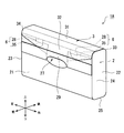
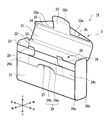
- FIG.1 and FIG.2 is a perspective view of the package 1 which concerns on 1st Embodiment, and has shown the state which looked at the package 1 from the front right diagonal side.
- the package 1 includes a case body 2 and a tan grid 3.
- the case body 2 has an upper surface opened.
- Reference numeral 20 denotes an opening formed at the upper end of the case body 2.
- the tan grid 3 is connected to the rear edge of the opening surface 20 of the case body 2 and is a lid member that opens and closes the opening surface 20.
- the tan grid 3 is closed in the state shown in FIG. 1, and the tan grid 3 is opened in the state shown in FIG.
- the package 1 has a so-called clutch bag shape, and can be said to be a clutch bag type package.
- the case body 2 is a box having a substantially rectangular parallelepiped shape, and a cigarette package (hereinafter referred to as “inner pack”) 4 is accommodated therein as shown in FIG.
- the inner pack 4 is obtained by wrapping a bundle of cigarettes (not shown) with an inner packaging material 5.
- the inner packaging material 5 is, for example, a sheet-like aluminum vapor-deposited paper having a rectangular shape, and is formed to include a paper base material and an aluminum film vapor-deposited on the surface thereof.
- 3a and 5b shown in FIG. 3 are a pair of trapezoidal side flaps formed by overlapping the outer peripheral edges of the inner packaging material 5 and folding them.
- the cigarette bundle is wrapped with the inner packaging material 5 so that the side flaps 5a and 5b face the circumferential surface of the cigarette instead of the end in the longitudinal direction. According to this, when the consumer takes out the cigarette, the end of the cigarette can be hardly caught on the inner packaging material 5.
- the chain line shown in FIG. 3 represents a separation line. A consumer who has purchased the package 1 containing the inner pack 4 picks and pulls the side flap 5a on the near side of the inner pack 4 and separates it at the separation line to expose the cigarette to the outside of the inner packaging material 5. be able to.
- the case body 2 has a front wall 21, a rear wall 22, a left side wall 23, a right side wall 24, and a bottom wall 25, and the outer shape is defined by these.
- the front wall 21 and the rear wall 22 have the same shape and are arranged to face each other.
- the front wall 21 and the rear wall 22 are connected to each other by a left side wall 23, a right side wall 24, and a bottom wall 25.
- the edge 26a located at the boundary between the front wall 21 and the bottom wall 25 and the edge 26b located at the boundary between the rear wall 22 and the bottom wall 25 are round corners (round edges) having a round shape. Yes.
- the front wall 21 of the case body 2 is provided with a slit-like insertion opening 27.
- the insertion opening 27 is disposed above the center of the front wall 21 in the height direction, that is, at a portion near the opening surface 20.
- FIG. 1 and FIG. 2 show the front, rear, top, bottom, left and right directions in the package 1.
- the up-down direction, the left-right direction, and the front-back direction shown in the figure correspond to the height direction, the width direction, and the depth direction of the package 1 (case body 2), respectively.
- the insertion opening 27 extends along the width direction of the front wall 21.
- the width direction of the package 1 (case body 2) is a dimension in the direction along the rear edge of the opening surface 20.
- the height direction of the package 1 (case body 2) is a dimension in a direction perpendicular to the width direction and along the front wall 21.
- the tan grid 3 is connected to the rear wall 22 of the case body 2 with the upper edge as a fold line, that is, a self hinge.
- the tongue grid 3 includes a lid 31 (lid portion) and a tongue 32 (tongue portion) from the rear wall 22 side.
- the lid 31 and the tongue 32 are connected via a folding line.
- the lid 31 and the tongue 32 divide the tan grid 3 with the folding line as a boundary.
- the boundary portion between the rear wall 22 and the lid 31 is referred to as a lid folding portion 33
- the boundary portion between the lid 31 and the tongue 32 is referred to as a tongue folding portion 34.
- the lid folding part 33 and the tongue folding part 34 are both round corners having a round shape.
- the lid 31 has a shape and a size corresponding to the opening surface 20 of the case body 2, and is a lid member that can cover the opening surface 20 so as to be freely opened and closed by being connected to the rear edge of the opening surface 20. It is.
- the tongue 32 has the same width as the lid 31 and once extends, and then the width gradually decreases.
- An insertion piece 32 a is formed on the distal end side of the tongue 32 so as to protrude. The width of the insertion piece 32 a is slightly smaller than the insertion opening 27 provided in the front wall 21 of the case body 2.
- the tongue 32 overlaps the front wall 21 of the case body 2, and the insertion piece 32 a of the tongue 32 is inserted into the insertion opening 27.
- the lid 31 closes the opening surface 20 of the case body 2, and access to the cigarette that is an object to be accommodated in the package 1 is restricted.
- the package 1 which concerns on this embodiment becomes a specification which accommodates the inner pack 4 in the case main body 2 so that the longitudinal direction of a cigarette corresponds to the width direction of the package 1.
- FIG. Yes. the package 1 (case body 2) has a width dimension larger than a height dimension.
- the case body 2 is usually printed with characters, designs, photographs, and the like for advertising, advertising, and other purposes.
- the front wall 21 of the case body 2 is more easily noticed by consumers compared to other surfaces, there is a demand for securing a larger area as a printing space for characters, pictures, and the like on the front wall 21. .
- the package 1 is a tan grid type package
- the information display space for advertisements, advertisements, etc. on the front wall 21 of the case body 2 is below the insertion opening 27.
- the insertion opening 27 must be provided at an upper position of the front wall 21, that is, at a location relatively close to the opening surface 20.
- the insertion opening 27 is provided at a position on the upper end side (that is, the opening surface 20 side) from the center in the height direction of the front wall 21.
- the package 1 stores the inner pack 4 so that the longitudinal direction of the cigarette matches the width direction of the case body 2, so that the longitudinal direction of the cigarette matches the height direction of the case body 2.
- the height dimension of the front wall 21 itself becomes smaller.
- the restoring force of the blank generated in the lid folding part 33 and the tongue folding part 34 acts on the tan grid 3,
- the insertion piece 32a is easily pulled out from the insertion opening 27. That is, a situation in which the tan grid 3 opens carelessly easily occurs.
- the package 1 according to the present embodiment is provided with a lock structure 6 for suppressing the above problems and improving the lid closing.
- the lock structure 6 is formed by an engaging portion formed on each of the tongue 32 and the front wall 21, and prevents the insertion piece 32 a from coming out of the insertion opening 27 by the engagement between the engagement portions. is there.
- the lock structure 6 is configured by a combination of a locking tongue piece 28 (locking piece) provided on the front wall 21 of the case body 2 and a folded piece 35 (locking piece) provided inside the tongue 32. ing.
- the locking tongue piece 28 is a rectangular tongue piece protruding from the upper edge of the front wall 21. In the example shown in FIGS. 1 and 2, locking tongue pieces 28 are provided at two locations on the upper edge of the front wall 21.
- the folded piece 35 is formed by folding the tip end side of the tongue 32 and partially adhering both end sides of the folded portion to the inner surface of the opposing tongue 32.
- the folded piece 35 in the present embodiment is formed on both sides of the insertion piece 32a.
- a portion (hereinafter referred to as “flap engaging portion”) 35 a corresponding to the locking tongue piece 28 provided on the front wall 21 in the width direction of the package 1 is bonded to the inner surface of the tongue 32.
- both end portions are bonded to the inner surface of the tongue 32.
- a predetermined gap is formed between the flap engaging portion 35a of the folded piece 35 and the inner surface of the tongue 32 so that the locking tongue piece 28 is sandwiched when the tongue grid 3 is closed.
- the package 1 of this embodiment includes two pairs of folded pieces 35 and locking tongue pieces 28 that are engaged with each other when the tongue grid 3 is closed, but the number thereof is not particularly limited.
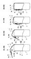
- FIG. 4 shows each state from the opened state to the closed tan grid 3 of the package 1.
- the first to fourth states are shown from the left side to the right side.
- the cross section of the package 1 shown in FIG. 4 corresponds to the AA cross section of FIG.
- the first state shown in FIG. 4 shows a state where the package 1 is opened.
- the locking tongue piece 28 protrudes upward from the upper edge of the front wall 21.
- the handler performs the closing operation of the tan grid 3 in order to close the package 1.
- the outer surface 35b of the folded piece 35 provided on the tongue 32 is brought into a second state in which the outer surface 35b contacts the inner surface 28a of the locking tongue piece 28 provided on the upper edge of the front wall 21. And migrate.
- the inner surface 28 a of the locking tongue piece 28 is a surface of the locking tongue piece 28 that faces the opening surface 20 in the case body 2.
- the outer surface 35 b of the folded piece 35 is pressed against the inner surface 28 a of the locking tongue piece 28 in accordance with the closing operation of the tan grid 3.
- position of the latching tongue piece 28 inclines toward the case main body 2 frontward from the connection base end part with the upper edge of the front wall 21 as a boundary.
- the third state is obtained.
- the pressing degree of the locking tongue piece 28 by the folded piece 35 is further advanced as compared to the second state.
- the fourth state is obtained. That is, the folding piece 35 and the locking tongue piece 28 engage with each other in the process in which the insertion piece 32 a is inserted into the insertion opening 27.
- the folded piece 35 and the locking tongue piece 28 are locked with each other, and the package 1 is closed by the lid 31 closing the opening surface 20. It becomes a state.
- the locking tongue piece 28 gets over the folded piece 35, that is, when the folded piece 35 and the locked tongue piece 28 are locked to each other, the locked tongue piece 28 is folded back. A sound is produced by being played by the piece 35. As described above, the sound generated when the folded piece 35 and the locking tongue piece 28 are locked to each other enables the user to confirm that the package 1 is surely closed. The feeling of use can be improved.
- the restoring force of the blank is larger than that of a square shape. Is big.
- the tongue 32 has a relationship of securing a display space such as a health warning on the front wall 21.
- the arrangement position of the insertion opening 27 for inserting the insertion piece 32 a tends to be near the upper edge of the front wall 21.
- FIG. 5 is a development view of the blank B1 forming the package 1 according to the present embodiment.
- the blank B1 is made of paper such as card paper or Manila cardboard, but is not limited thereto.
- the blank B1 may be manufactured using a plastic sheet or aluminum vapor-deposited paper.
- the blank B1 has a front wall panel P1 which becomes the front wall 2 of the case body 2.
- An insertion opening 27 is formed in the front wall panel P1.
- a left side wall 23 of the case main body 2 On both sides of the front wall panel P1, a left side wall 23 of the case main body 2, a left side wall panel P2 which is a part of the right side wall 24, and a right side wall panel P3 are connected, and a bottom wall 25 is provided at the upper end of the front wall panel P1.
- the bottom wall panel P4 which becomes is continued.
- the bottom wall panel P4 is connected to a rear wall panel P5 which is located on the opposite side of the front wall panel P1 and serves as the rear wall 22 of the case body 2. Further, reinforcing flaps P6 and P7 are connected to both ends of the bottom wall panel P4.
- the rear wall panel P5 is connected with a lid panel P8 which is located on the opposite side of the bottom wall panel P4 and becomes the lid 31. Further, an inner side flap P9 that is the remaining portion of the left side wall 23 of the case body 2 and an inner side flap P10 that is the remaining portion of the right side wall 24 are connected to both sides of the rear wall panel P5.
- the left side wall panel P2, the reinforcing flap P6, and the inner side flap P9 are bonded together to form the left side wall 23.
- the right side wall panel P3, the reinforcing flap P7, and the inner side flap P10 are bonded together to form the right side wall 24.
- the tongue panel P11 which becomes the tongue 32 is connected to the upper end of the lid panel P8.
- An insertion piece region R1 to be an insertion piece 32a is formed on the distal end side of the tongue panel P11.
- folded flaps P12 and P13, which are folded pieces 35, are connected to both sides of the insertion piece region R1 in the tongue panel P11.
- two tabs T1 and T2 serving as the locking tongue pieces 28 are connected to the lower end of the front wall panel P1.
- the boundary between the front wall panel P1 and the bottom wall panel P4 and the rear wall panel P5 As shown in FIG. 5, the boundary between the front wall panel P1 and the bottom wall panel P4, the boundary between the bottom wall panel P4 and the rear wall panel P5, the boundary between the rear wall panel P5 and the lid panel P8, and the tongue between the lid panel P8 and the tongue.
- the border with the panel P11 is provided with a plurality of narrow-pitch folding lines indicated by alternate long and short dashed lines, and a round corner (edge) is formed by folding with the narrow-pitch folding lines.
- the blank B1 configured as described above is folded from the folding line indicated by the alternate long and short dash line to form the case main body 2 and the tan grid 3, and by this folding molding, the package 1 as shown in FIG. can get.
- the inner pack 4 is placed on the rear wall panel P5.
- the bottom wall panel P4 the reinforcing flaps P6 and P7, the lid panel P8, the inner side flaps P9 and 10, the front wall.
- the panel P1 is folded.
- the left side wall panel P2, the reinforcing flap P6, and the inner side flap P9 are bonded to each other, and the right side wall panel P3, the reinforcing flap P7, and the inner side flap P10 are bonded to each other.
- the folding flaps P12 and P13 are folded with respect to the tongue panel P11, and both end portions of the folding flaps P12 and P13 are bonded to the tongue panel P11.
- the case where the left side wall panel P2, the reinforcing flap P6, and the inner side flap P9 are bonded to each other has been described. However, it is sufficient that at least the left side wall panel P2 and the inner side flap P9 are bonded.
- the flap P6 may not be bonded to the left side wall panel P2 and the inner side flap P9.
- the reinforcing flap P7, and the inner side flap P10 as long as at least the right side wall panel P3 and the inner side flap P10 are bonded, the reinforcing flap P7 is the right side wall panel P3 and the inner side flap P10. It may not be bonded to P10.
- the above-mentioned flap engaging part 35a is formed by the non-adhesion area
- FIG. 6 and 7 are perspective views of the package 1A according to the second embodiment.
- FIG. 8 is a development view of the blank B2 forming the package 1A.
- the same components as those in the package 1 according to the first embodiment are denoted by the same reference numerals, and detailed description thereof is omitted.
- the package 1A according to the second embodiment will be described focusing on differences from the package 1 according to the first embodiment.
- FIG. 6 shows the package 1A in a state in which the tan grid 3 is closed
- FIG. 7 shows the package 1A in a state in which the tan grid 3 is opened.
- the insertion opening 27 for inserting the insertion piece 32a of the tongue grid 3 (the tongue 32) is formed by punching the front wall 21, but in the second embodiment, the case main body 2
- An insertion band member 29 is provided on the front wall 21.
- the insertion band member 29 has an inner band member 29a and an outer band member 29b.
- the inner belt member 29a is connected to the upper edge of the front wall 21 and is folded back onto the front wall 21 from the folding line.
- Outer band member 29b is connected to the end of inner band member 29a located on the opposite side of the connection end with the upper edge of front wall 21 via a folding line.
- the outer side band member 29b is overlapped on the inner side band member 29a by being folded back from the folding line with respect to the inner side band member 29a.
- the outer band member 29b has a larger dimension in the width direction of the package 1A than the inner band member 29a, and both side end portions 29c are directly bonded to the front wall 21.
- a slit-like insertion opening 27 is opened at the boundary between the inner band member 29a and the outer band member 29b, and the insertion piece 32a of the tongue 32 can be inserted into the insertion opening 27.
- the insertion piece 32a in the tongue 32 is inserted into the insertion opening 27 while being inserted into a gap formed between the inner band member 29a and the outer band member 29b.
- the insertion piece 32 a is inserted into the insertion opening 27, whereby the opening surface 20 of the case body 2 is closed by the lid 31 of the tan grid 3.
- the folded piece 35 and the locking tongue piece 28 are engaged with each other to be locked. Therefore, similarly to the package 1 according to the first embodiment, it is possible to prevent the insertion piece 32a of the tongue 32 from being inadvertently pulled out from the insertion opening 27 on the case body 2 side.
- an insertion band inner panel P14 that becomes the inner band member 29a of the insertion band member 29 is connected to the lower end of the front wall panel P1.
- This insertion band inner panel P14 is connected to an insertion band outer panel P15 which is located on the opposite side of the front wall panel P1 and serves as the outer band member 29b of the insertion band member 29.
- a folding line is formed between the insertion band inner panel P14 and the insertion band outer panel P15, and an opening R2 is perforated so as to straddle both.
- the opening R2 has an elliptical shape, and the long axis position thereof coincides with the position of the folding line. However, the shape of the opening R2 can be changed as appropriate.
- the width dimension of the insertion band outer panel P15 is larger than the width dimension of the insertion band inner panel P14.
- the width dimension here is a dimension in the direction corresponding to the width direction in the package 1A after assembly, and is a dimension along the folding line between the insertion band inner panel P14 and the insertion band outer panel P15.
- the case main body 2 and the tan grid 3 are formed by being folded from the folding line indicated by the alternate long and short dash line, and the package 1A as shown in FIG. 6 is obtained.
- the insertion band inner panel P14 is folded on the outer surface side of the front wall panel P1.
- the insertion band outer panel P15 is folded from the folding line so as to be superimposed on the insertion band inner panel P14.
- both ends of the insertion band outer panel P15 directly overlap the front wall panel P1.
- the insertion band member 29 is fixed to the front wall 21 of the case body 2 by adhering portions (both end portions) directly overlapping the front wall panel P1 of the insertion band outer panel P15 to the front wall panel P1. Has been.
- the insertion band inner panel P14 and the insertion band outer panel P15 are not bonded to each other. Therefore, a gap is formed between the insertion band inner panel P14 and the insertion band outer panel P15.
- the insertion piece 32 a can access the insertion opening 27 using the gap, and the insertion piece 32 a can be inserted into the insertion opening 27.
- the package 1A shown in FIG. 6 is completed by the above folding molding.
- the same effects as the package 1 according to the first embodiment can be obtained. That is, since the insertion piece 32a of the tongue 32 can be prevented from inadvertently slipping out of the insertion opening 27 on the case body 2 side from the state in which the tongue grid 3 is closed, it is possible to provide the package 1A with excellent lid closure. It is.
- the lock structure 6 in each of the embodiments described above is configured by a combination of the locking tongue piece 28 provided on the front wall 21 of the case body 2 and the folded piece 35 provided on the tongue 32.
- the present invention is not limited to this, and various forms and structures can be adopted as the lock structure 6. That is, the lock structure 6 can include an engaging portion that is formed on each of the front wall 21 and the tongue 32 and that engages with each other in the process of inserting the insertion piece 32 a into the insertion opening 27.
- the engaging portion is not limited to the combination of the locking pieces, and may be a combination of the locking piece and the engaging hole that engages with the locking piece, for example.
- the insertion piece 32 a formed on the tan grid 3 side is inserted into the case body 2 side.
- the form inserted in the part 27 is employ
- the tan grid type package 1 and 1A demonstrated the case where the lid folding part 33, the tongue folding part 34, the edge part 26a, and the edge part 26b were round shape
- the said corner part May be chamfered in a planar shape or square.
- each above-mentioned embodiment demonstrated the case where cigarettes, such as a filter cigarette and a double-cut cigarette, were accommodated as a suitable application example of the to-be-contained object accommodated in the packages 1 and 1A, it is not limited to these.
- cigars cigars
- electronic cigarettes chewing cigarettes, snuff cigarettes and the like
- articles such as confectionery and gum
- the dimensions, materials, shapes, relative arrangements, and the like of the constituent elements described in the embodiments are not intended to limit the technical scope of the invention only to those unless otherwise specified. .
- each embodiment and its modification can be implemented in combination as much as possible.
Landscapes
- Engineering & Computer Science (AREA)
- Mechanical Engineering (AREA)
- Cartons (AREA)
- Packaging Of Annular Or Rod-Shaped Articles, Wearing Apparel, Cassettes, Or The Like (AREA)
Description
本発明は、タングリッド型パッケージに関する。
従来、シガレットやフィルタシガレット等の棒状喫煙物品を収容するボックスタイプのハードパッケージの1形態として、ヒンジリッド型パッケージが広く知られている。この種のヒンジリッド型パッケージは、リッドも箱形をなしているのが一般的であるが、この箱形リッドに代えてタングリッドを備えたタングリッド型パッケージも知られている(例えば、特許文献1を参照)。
タングリッド型パッケージのタングリッドは、通常、ケース本体の開口面の縁部に折り込み線を介して接続されており、この開口面を開閉可能に覆うリッドと、このリッドから折り込み線を介して接続されるタングとを有する。タングリッド型パッケージの一例として、ケース本体の前壁には、リッドによって開口面を覆う際に、タングの先端側に形成された差し込み片を差し込み可能な差し込み口が設けられているものが知られている。
タングリッド型パッケージは、1枚のブランクから形成可能であり、資源の有効利用を図る点で優れている。しかしながら、タングリッド型パッケージは、通常、リッドとケース本体との接続部及びリッドとタングとの接続部に折り込み線が介在しており、折り込まれたブランクが元に戻ろうとする復元力によって、差し込み口から差し込み片が抜け出し易く、蓋閉まり性が悪化する虞がある。
本発明は、このような課題に鑑みてなされてものであって、その目的は、従来に比べて蓋閉まり性の優れたタングリッド型パッケージに関する技術を提供することにある。
上記課題を解決するために、本発明に係るタングリッド型パッケージは、以下の手段を採用した。すなわち、本発明に係るタングリッド型パッケージは、開口面を有するとともに内部に物品を収容可能なケース本体と、前記開口面の後縁に連設されるとともに該開口面を開閉自在に覆う蓋部、及び、前記蓋部に連設された舌部を有するタングリッドと、を備え、前記タングリッドが閉じられる際に、前記ケース本体の前壁と前記舌部の何れか一方に形成された差し込み口に対して他方に形成された差し込み片が差し込み可能に形成されており、前記舌部及び前記前壁の双方に形成されて、前記タングリッドが閉じられる際に前記差し込み片が前記差し込み口に差し込まれる過程で互いに係合する係合部を更に備える。
本発明に係るタングリッド型パッケージは、差し込み口がケース本体の前壁に設けられる場合にはタングリッドの舌部に差し込み片が設けられ、差し込み口がタングリッドの舌部に設けられる場合にはケース本体の前壁に差し込み片が設けられる。
本発明に係るタングリッド型パッケージによれば、タングリッドが閉じられる際に差し込み片が差し込み口に差し込まれる過程において、ケース本体における前壁と舌部の双方に形成された係合部が互いに係合するため、差し込み片が差し込み口から不用意に抜け出すことを抑制できる。従って、タングリッド型パッケージの蓋閉まり性を従来に比べて向上させることが可能となる。なお、前記係合部は、前記前壁側に設けられた係止片と、前記舌部側に設けられた係止片の組み合わせにより構成されていてもよい。タングリッドを閉じる際に、ケース本体の前壁側に設けられた係止片と、舌部側に設けられた係止片とが掛り止められることで互いにロックされ、差し込み片が差し込み口から不用意に抜け出すことを好適に抑制できる。
また、タングリッド型パッケージにおいて、前記蓋部と前記開口面の後縁との境界部、及び、前記蓋部と前記舌部との境界部のうち少なくとも一方はラウンドコーナーであってもよい。また、前記ケース本体のうち、前記開口面の後縁に沿った幅方向の寸法が、該幅方向に直交して且つ前記前壁に沿った高さ方向の寸法に比べて大きくてもよい。前者の場合、パッケージを形成するために折り込まれたブランクが元の形状に戻ろうとする復元力が大きくなりやすく、差し込み口から差し込み片が抜け出しやすい条件といえる。後者の場合、ケース本体の前壁に形成された差し込み口(或いは、差し込み片)と前壁上端との寸法を十分に確保しにくく、この場合もやはり差し込み口から差し込み片が抜け出しやすい条件といえる。このように蓋閉まり性が悪化しやすい条件下においても、本発明に係るパッケージによれば、タングリッドが閉じられる際に差し込み片が差し込み口に差し込まれる過程で互いに係合する係合部を備えるようにしたので、不用意に差し込み口から差し込み片が抜け出すことを抑制できる。
なお、タングリッド型パッケージに収容する被収容物は特に限定されるものではないが、例えば、たばこ商品を被収容物として好適に例示できる。たばこ商品としては、例えば紙巻たばこ(フィルタシガレット、両切たばこ(フィルタ無し))、シガー(葉巻)、電子たばこ、噛みたばこ、嗅ぎたばこ等が例示できる。また、タングリッド型パッケージは、例えば菓子、ガム等を収容するパッケージであってもよい。
また、本発明における課題を解決するための手段は、可能な限り組み合わせて採用することができる。
本発明によれば、従来に比べて、タングリッド型パッケージにおける蓋閉まり性を向上させることができる。
以下、本発明に係るタングリッド型パッケージ(以下、単に“パッケージ”という)の実施形態について、図面に基づいて説明する。本発明が適用されるパッケージに収容する被収容物は特定のものに限定されないが、この実施形態ではシガレットをパッケージに収容する場合を例に説明する。
〈第1実施形態〉
図1及び図2は、第1実施形態に係るパッケージ1の斜視図であり、パッケージ1を正面右斜め側から眺めた状態を示している。パッケージ1は、ケース本体2及びタングリッド3を備えている。ケース本体2は上面が開口されている。符号20は、ケース本体2の上端に形成された開口面を示している。タングリッド3は、ケース本体2の開口面20の後縁に連設されており、開口面20を開閉する蓋部材である。図1に示す状態においてタングリッド3が閉じられており、図2に示す状態においてタングリッド3が開かれている。なお、パッケージ1は、いわゆるクラッチバッグの形状を有しており、クラッチバッグ型パッケージともいえる。
図1及び図2は、第1実施形態に係るパッケージ1の斜視図であり、パッケージ1を正面右斜め側から眺めた状態を示している。パッケージ1は、ケース本体2及びタングリッド3を備えている。ケース本体2は上面が開口されている。符号20は、ケース本体2の上端に形成された開口面を示している。タングリッド3は、ケース本体2の開口面20の後縁に連設されており、開口面20を開閉する蓋部材である。図1に示す状態においてタングリッド3が閉じられており、図2に示す状態においてタングリッド3が開かれている。なお、パッケージ1は、いわゆるクラッチバッグの形状を有しており、クラッチバッグ型パッケージともいえる。
ケース本体2は、略直方体形状を有した箱体であり、その内部には図3に示すようにシガレットの包装体(以下、「インナパック」という)4が収容されている。インナパック4は、シガレット(図示せず)の束を、内包材5により包み込んだものである。内包材5は、例えば矩形状を有するシート状のアルミニウム蒸着紙であり、紙基材と、その表面に蒸着されたアルミニウムの膜とを含んで形成されている。図3に示す5a,5bは、内包材5の外周縁同士を重ね合わせて折り込むことによって形成された台形形状の一対のサイドフラップである。本実施形態では、シガレットにおける長手方向の端部ではなく、その周面にサイドフラップ5a,5bが面して配置されるようにシガレットの束を内包材5によって包みこむ。これによれば、消費者がシガレットを取り出す際に、内包材5にシガレットの端部を引っ掛かりにくくすることができる。なお、図3中に示す鎖線は、切り離し線を表したものである。インナパック4が収容されたパッケージ1を購入した消費者は、インナパック4における手前側のサイドフラップ5aを摘んで引っ張り、切り離し線を境に切り離すことにより、シガレットを内包材5の外部に露出させることができる。
ケース本体2は、前壁21、後壁22、左側壁23、右側壁24、底壁25を有し、これらによって外形が画定されている。前壁21及び後壁22は同形状を有し、対向配置されている。これら前壁21及び後壁22は、左側壁23と右側壁24と底壁25とによって相互に連結されている。ここで、前壁21と底壁25との境界に位置する縁部26a、後壁22と底壁25との境界に位置する縁部26bはラウンド形状を有するラウンドコーナー(ラウンドエッジ)となっている。
更に、ケース本体2の前壁21には、スリット状の差し込み開口部27が設けられている。差し込み開口部27は、前壁21の高さ方向中央よりも上側、すなわち開口面20寄りの部分に配置されている。ここで、図1及び図2に、パッケージ1における前後、上下、左右の各方向を示す。なお、図示の上下方向、左右方向、前後方向は、それぞれパッケージ1(ケース本体2)の高さ方向、幅方向、奥行方向に対応している。図1及び図2に示すように、差し込み開口部27は、前壁21の幅方向に沿って伸びている。なお、パッケージ1(ケース本体2)の幅方向は、開口面20の後縁に沿った方向の寸法である。また、パッケージ1(ケース本体2)の高さ方向は、上記幅方向に直交して且つ前壁21に沿った方向の寸法である。
ケース本体2の後壁22には、その上縁を折り込み線、すなわちセルフヒンジとしてタングリッド3が連結されている。タングリッド3は、後壁22側からリッド31(蓋部)及びタング32(舌部)を有している。これらリッド31とタング32とは、折り込み線を介して連なっている。言い換えると、リッド31とタング32とは、折り込み線を境にタングリッド3を区分している。以下、後壁22とリッド31との境界部をリッド折り込み部33と称し、リッド31とタング32との境界部をタング折り込み部34と称する。本実施形態において、リッド折り込み部33とタング折り込み部34とは、共にラウンド形状を有するラウンドコーナーとなっている。
リッド31は、ケース本体2の開口面20に対応する形状及び大きさを有しており、開口面20の後縁に連設されることで開口面20を開閉自在に覆うことができる蓋部材である。タング32は、リッド31と同一の幅を有して一旦伸びた後、その幅が徐々に狭まる形状となっている。タング32の先端側には、差し込み片32aが突出するように形成されている。差し込み片32aの幅は、ケース本体2における前壁21に設けられた差し込み開口部27よりも若干小さな寸法となっている。
図1に示すように、タングリッド3が閉じられる際には、タング32は、ケース本体2の前壁21に重なり合うとともに、タング32の差し込み片32aが差し込み開口部27に差し込まれる。これにより、ケース本体2の開口面20をリッド31が塞ぎ、パッケージ1に収容されている被収容物であるシガレットへのアクセスが規制されることになる。
ところで、図1及び図2に示すように、本実施形態に係るパッケージ1は、シガレットの長手方向がパッケージ1の幅方向に対応するようにインナパック4をケース本体2に収容する仕様となっている。そのため、パッケージ1(ケース本体2)は、その幅寸法が高さ寸法よりも大きい。また、図1及び図2において図示を省略しているが、通常、ケース本体2には、宣伝、広告、その他の目的のために、文字、絵柄、写真等などが印刷されている。特に、ケース本体2の前壁21は、他の面に比べて消費者の目にも留まりやすいため、前壁21において、より大きな面積を文字、絵柄等の印刷スペースとして確保したいという要請がある。
ここで、パッケージ1はタングリッド型のパッケージであるため、ケース本体2の前壁21における宣伝、広告等の情報表示スペースは、差し込み開口部27よりも下方になる。前壁21における差し込み開口部27の上方部位は、タングリッド3が閉じられた際にタング32の下に隠れてしまうからである。従って、ケース本体2の前壁21における情報表示スペースをより多く確保する観点から、差し込み開口部27を前壁21の上部位置、すなわち開口面20に比較的近い箇所に設けざるを得ないことが多い。本実施形態のパッケージ1においても、差し込み開口部27が前壁21の高さ方向中央よりも上端側(すなわち、開口面20側)の位置に設けられている。
更に、本実施形態に係るパッケージ1は、シガレットの長手方向がケース本体2の幅方向に一致するようにインナパック4を収納するため、シガレットの長手方向をケース本体2の高さ方向に一致させる場合に比べて、前壁21の高さ寸法自体が小さくなる。そうすると、リッド折り込み部33及びタング折り込み部34において発生するブランクの復元力、より詳しくはブランクが折り込まれる前の元の形状に戻ろうとする復元力が、タングリッド3に対して作用することにより、差し込み開口部27から差し込み片32aが抜け出しやすくなる。つまり、タングリッド3が不用意に開いてしまうという状況が起こり易くなる。
そこで、本実施形態に係るパッケージ1においては、上記不具合を抑制し、蓋閉まりを良くするためのロック構造6を備えている。ロック構造6は、タング32と前壁21との各々に形成される係合部によって形成され、この係合部同士の係合によって差し込み開口部27からの差し込み片32aの抜け出しを抑制するものである。
ロック構造6は、ケース本体2における前壁21に設けられた係止舌片28(係止片)と、タング32の内側に設けられた折り返し片35(係止片)との組み合わせによって構成されている。係止舌片28は、前壁21の上縁から突出している矩形状の舌片である。図1及び図2に示す例においては、前壁21の上縁の2箇所に係止舌片28が設けられている。
折り返し片35は、タング32の先端側を折り返し、その折り返された部分の両端側を対向するタング32内面に部分的に接着することで形成されている。本実施形態における折り返し片35は、差し込み片32aの両側に形成されている。また、各折り返し片35のうち、パッケージ1の幅方向において前壁21に設けられた係止舌片28に対応する部位(以下、「フラップ係合部」という)35aはタング32内面と接着されず、両端部分がタング32内面と接着されている。これにより、折り返し片35におけるフラップ係合部35aとタング32内面との間には、タングリッド3が閉じられた際に係止舌片28が挟み込まれる程度の所定の隙間が形成される。本実施形態のパッケージ1においては、タングリッド3を閉じる際に互いに係合する2対の折り返し片35と係止舌片28とを備えているが、その数は特に限定されない。
次に、図4を参照して、パッケージ1を閉じる際の動作状況について説明する。図4は、パッケージ1のタングリッド3が開かれた状態から閉じられるまでの各状態を示している。左側から右側に向かって第1~第4状態を示している。なお、図4に示すパッケージ1の断面は、図1のA-A断面に対応している。
図4に示す第1状態は、パッケージ1が開かれた状態を示している。また、第1状態において、係止舌片28は、前壁21の上縁から上方に向かって突出している。
次に、扱い者は、パッケージ1を閉じるべく、タングリッド3の閉じ動作を行う。タングリッド3の閉じ動作が開始されると、タング32に設けられた折り返し片35の外面35bが前壁21の上縁に設けられた係止舌片28の内面28aに当接する第2状態へと移行する。係止舌片28の内面28aは、係止舌片28のうち、ケース本体2における開口面20を臨む方の面である。
第2状態においては、タングリッド3の閉じ動作に伴い、折り返し片35の外面35bが係止舌片28の内面28aに押し付けられる。これにより、係止舌片28の姿勢は、前壁21の上縁との接続基端部を境にケース本体2前方に向かって傾倒する。このように、折り返し片35によって係止舌片28を前壁21方向に押し付けつつ、タング32の差し込み片32aが差し込み開口部27に差し込まれると、第3状態となる。第3状態では、第2状態に比べて折り返し片35による係止舌片28の押し付け度合いが更に進展している。
そして、差し込み開口部27に対する差し込み片32aの差し込み量(長さ)が増加していくと、折り返し片35の外面35bが係止舌片28の内面28aを乗り越えることで第4状態となる。つまり、差し込み片32aが差し込み開口部27に差し込まれる過程で折り返し片35と係止舌片28とが互いに係合する。このように、第4状態においては、折り返し片35と係止舌片28とが互いに係止されることでロック状態になると共に、リッド31によって開口面20が塞がれることでパッケージ1が閉状態となる。また、係止舌片28が折り返し片35を乗り越える際、すなわち、折り返し片35と係止舌片28とが互いに係止されることでロック状態になる際には、係止舌片28が折り返し片35に弾かれることにより音が鳴る。このように、折り返し片35と係止舌片28とが互いに係止される際に発生する音によって、使用者はパッケージ1が確実に閉状態となったことを確認することができ、パッケージ1の使用感を向上させることができる。
本実施形態に係るパッケージ1によれば、タングリッド3が閉じられた状態において、ケース本体2とリッド31との間のリッド折り込み部33や、リッド31とタング32との間のタング折り込み部34といった箇所で発生するブランクの復元力(反発力)がタングリッド3に作用しても、折り返し片35と係止舌片28とが相互に係止されることにより、タング32の差し込み片32aがケース本体2側の差し込み開口部27から抜け出すことを抑制できる。従って、タングリッド型のパッケージ1の蓋閉まり性を従来に比べて向上させることが可能となる。
特に、本実施形態に係るパッケージ1のように、リッド折り込み部33やタング折り込み部34がラウンド(round)形状となっている場合には、スクエア(square)形状の場合に比べてブランクの復元力が大きい。更に、パッケージ1のように、シガレットの長手方向がケース本体2の幅方向に沿うようにインナパック4を収容する場合、前壁21においてヘルスワーニング等の表示スペースを確保する関係上、タング32の差し込み片32aを差し込むための差し込み開口部27の配置位置が前壁21の上縁近傍になりがちである。このような条件下においても、パッケージ1によれば、タングリッド3を閉じた際に互いに係合する折り返し片35と係止舌片28との組み合わせからなるロック構造6を具備することにより、タングリッド3が不用意に開かれてしまうことを抑制できる。
図5は、本実施形態に係るパッケージ1を形成するブランクB1の展開図である。ブランクB1にはカード紙、マニラボール紙等の紙材を用いているが、これに限られるものではない。例えばプラスチックシートやアルミ蒸着紙を用いてブランクB1を製造してもよい。
ブランクB1は、ケース本体2の前壁2となる前壁パネルP1を有している。前壁パネルP1には、差し込み開口部27が形成されている。前壁パネルP1の両側には、ケース本体2の左側壁23、右側壁24の一部となる左側壁パネルP2、右側壁パネルP3が連なっており、前壁パネルP1の上端には底壁25となる底壁パネルP4が連なっている。この底壁パネルP4には、前壁パネルP1とは反対側に位置してケース本体2の後壁22となる後壁パネルP5が連なっている。また、底壁パネルP4の両端には、補強フラップP6,P7が連なっている。
後壁パネルP5には、底壁パネルP4とは反対側に位置してリッド31となるリッドパネルP8が連なっている。また、後壁パネルP5の両側には、ケース本体2の左側壁23の残部となるインナサイドフラップP9と、右側壁24の残部となるインナサイドフラップP10とが連なっている。左側壁パネルP2、補強フラップP6、及びインナサイドフラップP9が互いに接着されて左側壁23を形成する。また、右側壁パネルP3、補強フラップP7、及びインナサイドフラップP10が互いに接着されて右側壁24を形成する。
リッドパネルP8の上端には、タング32となるタングパネルP11が連なっている。このタングパネルP11の先端側には、差し込み片32aとなる差し込み片領域R1が形成されている。また、タングパネルP11における差し込み片領域R1の両サイドには、折り返し片35となる折り返しフラップP12,P13が連なっている。また、前壁パネルP1の下端には、係止舌片28となる2つのタブT1,T2が連なっている。
図5に示すように、前壁パネルP1と底壁パネルP4との境界、底壁パネルP4と後壁パネルP5との境界、後壁パネルP5とリッドパネルP8との境界、リッドパネルP8とタングパネルP11との境界は、一点鎖線で示した複数の狭ピッチによる折り込み線が設けられており、この狭ピッチの折り込み線による折り込みによってラウンドコーナー(エッジ)が形成される。
上記のように構成されるブランクB1は、一点鎖線で示した折り込み線からそれぞれ折り込まれることで、ケース本体2及びタングリッド3が形成され、この折り込み成形によって、図1に示すようなパッケージ1が得られる。
より詳しくは、後壁パネルP5にインナパック4が載置され、この状態でインナパック4に対して底壁パネルP4、補強フラップP6,P7、リッドパネルP8、インナサイドフラップP9,10、前壁パネルP1の折り込みがなされる。そして、左側壁パネルP2、補強フラップP6、及びインナサイドフラップP9が互いに接着され、かつ、右側壁パネルP3、補強フラップP7、及びインナサイドフラップP10が互いに接着される。更に、タングパネルP11に対して折り返しフラップP12,P13の折り込みがなされ、折り返しフラップP12,P13の両端部がタングパネルP11に対して接着される。なお、上記の例では左側壁パネルP2、補強フラップP6、及びインナサイドフラップP9を互いに接着する場合を説明したが、少なくとも左側壁パネルP2とインナサイドフラップP9とが接着されていればよく、補強フラップP6が左側壁パネルP2及びインナサイドフラップP9と接着されていなくてもよい。同様に、右側壁パネルP3、補強フラップP7、及びインナサイドフラップP10についても、少なくとも右側壁パネルP3とインナサイドフラップP10とが接着されていれば、補強フラップP7が右側壁パネルP3及びインナサイドフラップP10と接着されていなくてもよい。
なお、折り返しフラップP12,P13のうち、タングパネルP11と接着されない非接着領域によって、上述のフラップ係合部35aが形成される。このようにして、ケース本体2内にインナパック4を収容したパッケージ1を成形することができる。
〈第2実施形態〉
次に、第2実施形態に係るパッケージ1Aを説明する。図6及び図7は、第2実施形態に係るパッケージ1Aの斜視図である。図8は、パッケージ1Aを形成するブランクB2の展開図である。ここで、第1実施形態に係るパッケージ1と同一の構成要素については同一符号を付すことにより、その詳しい説明を割愛する。以下、第2実施形態に係るパッケージ1Aについて、第1実施形態に係るパッケージ1との相違点を中心に説明する。
次に、第2実施形態に係るパッケージ1Aを説明する。図6及び図7は、第2実施形態に係るパッケージ1Aの斜視図である。図8は、パッケージ1Aを形成するブランクB2の展開図である。ここで、第1実施形態に係るパッケージ1と同一の構成要素については同一符号を付すことにより、その詳しい説明を割愛する。以下、第2実施形態に係るパッケージ1Aについて、第1実施形態に係るパッケージ1との相違点を中心に説明する。
図6にはタングリッド3が閉じた状態、図7にはタングリッド3が開かれた状態のパッケージ1Aを示している。第1実施形態に係るパッケージ1では、タングリッド3(タング32)の差し込み片32aを差し込むための差し込み開口部27が、前壁21に打ち抜き形成されていたが、第2実施形態ではケース本体2の前壁21に差し込み帯部材29が設けられている。
差し込み帯部材29は、内側帯部材29a及び外側帯部材29bを有する。内側帯部材29aは、前壁21の上縁に連設されており、折り込み線から前壁21の上に折り返されている。内側帯部材29aのうち、前壁21上縁との接続端の反対側に位置する方の端部には、折り込み線を介して外側帯部材29bが連設されている。外側帯部材29bは、折り込み線から内側帯部材29aに対して折り返されることで、内側帯部材29aの上に重ねられている。図6及び図7に示すように、外側帯部材29bは内側帯部材29aに比べてパッケージ1Aの幅方向への寸法が大きく、その両側端部29cは前壁21に直接接着されている。
更に、内側帯部材29aと外側帯部材29bとの境界部には、スリット状の差し込み開口部27が開口しており、この差し込み開口部27にはタング32の差し込み片32aを差し込み可能となっている。より詳しくは、タングリッド3を閉じる際、タング32における差し込み片32aは、内側帯部材29aと外側帯部材29bとの間に形成された隙間に差し込まれつつ、差し込み開口部27に挿通される。このようにして、差し込み開口部27に差し込み片32aが差し込まれることで、タングリッド3のリッド31によってケース本体2の開口面20が塞がれる。タングリッド3の閉じ操作がなされる際、折り返し片35と係止舌片28とが互いに係合することでロック状態になる。そのため、第1実施形態に係るパッケージ1と同様に、タング32の差し込み片32aがケース本体2側の差し込み開口部27から不用意に抜け出すことを抑制できる。
図8に示すブランクB2は、前壁パネルP1の下端に、差し込み帯部材29の内側帯部材29aとなる差し込み帯インナパネルP14が連なっている。この差し込み帯インナパネルP14には、前壁パネルP1とは反対側に位置して差し込み帯部材29の外側帯部材29bとなる差し込み帯アウタパネルP15が連なっている。差し込み帯インナパネルP14と差し込み帯アウタパネルP15との間は折り込み線が形成されており、双方に跨るように開口部R2が穿孔されている。図8に示す例では、開口部R2は楕円形状を有し、その長軸位置が上記折り込み線の位置に一致している。但し、開口部R2の形状は適宜変更することができる。更に、差し込み帯アウタパネルP15の幅寸法は、差し込み帯インナパネルP14の幅寸法よりも大きい。ここでいう幅寸法とは、組み立て後におけるパッケージ1Aにおいて幅方向に対応する向きの寸法であり、差し込み帯インナパネルP14と差し込み帯アウタパネルP15との間の折り込み線に沿った方向の寸法である。
ブランクB2においても、上述したブランクB1と同様に、一点鎖線で示した折り込み線からそれぞれ折り込まれることで、ケース本体2及びタングリッド3が形成され、図6に示すようなパッケージ1Aが得られる。差し込み帯インナパネルP14は前壁パネルP1の外面側に折り込まれる。そして、差し込み帯アウタパネルP15は、差し込み帯インナパネルP14の上に重ねられるようにして、折り込み線から折り込まれる。
上述のように、差し込み帯アウタパネルP15は差し込み帯インナパネルP14よりも幅寸法が大きいため、差し込み帯アウタパネルP15の両端部は前壁パネルP1と直接重なり合う。本実施形態では、差し込み帯アウタパネルP15のうち、前壁パネルP1と直接に重なり合う部分(両端部分)を前壁パネルP1に接着することで、ケース本体2の前壁21に差し込み帯部材29が固定されている。
なお、パッケージ1Aの組み立て時において、差し込み帯インナパネルP14と差し込み帯アウタパネルP15とは互いに接着されない。そのため、差し込み帯インナパネルP14と差し込み帯アウタパネルP15との間には隙間が形成される。タングリッド3と閉じる際には、この隙間を利用して、差し込み片32aが差し込み開口部27へとアクセスすることが可能となり、差し込み片32aを差し込み開口部27に差し込むことができるようになる。以上のような折り込み成形によって、図6に示すパッケージ1Aが完成する。
以上のように構成されるパッケージ1Aによれば、第1実施形態に係るパッケージ1と同等の効果を奏する。すなわち、タングリッド3が閉じた状態から不用意にタング32の差し込み片32aがケース本体2側の差し込み開口部27から抜け出すことを抑制できるので、蓋閉まりの優れたパッケージ1Aを提供することが可能である。
〈変形例〉
以上、本発明の好適な実施形態を説明したが、上記実施形態には本発明の本旨を逸脱しない範囲において適宜の変更を加えることができる。例えば、上述の各実施形態におけるロック構造6は、ケース本体2の前壁21に設けられた係止舌片28とタング32に設けられた折り返し片35との組み合わせによって構成していたが、これに限られず、ロック構造6として種々の形態、構造を採用することができる。すなわち、ロック構造6は、前壁21及びタング32に各々形成されて且つ差し込み片32aが差し込み開口部27に差し込まれる過程において互いに係合する係合部を含んで構成することができる。ここで係合部は、係止片同士の組み合わせに限られず、例えば係止片とこの係止片と係合する係合孔との組み合わせであってもよい。
以上、本発明の好適な実施形態を説明したが、上記実施形態には本発明の本旨を逸脱しない範囲において適宜の変更を加えることができる。例えば、上述の各実施形態におけるロック構造6は、ケース本体2の前壁21に設けられた係止舌片28とタング32に設けられた折り返し片35との組み合わせによって構成していたが、これに限られず、ロック構造6として種々の形態、構造を採用することができる。すなわち、ロック構造6は、前壁21及びタング32に各々形成されて且つ差し込み片32aが差し込み開口部27に差し込まれる過程において互いに係合する係合部を含んで構成することができる。ここで係合部は、係止片同士の組み合わせに限られず、例えば係止片とこの係止片と係合する係合孔との組み合わせであってもよい。
また、上述の各実施形態においては、タングリッド型のパッケージ1,1Aとして、タングリッド3を閉じる際に、タングリッド3側に形成された差し込み片32aをケース本体2側に形成された差し込み開口部27に差し込む形態を採用しているが、差し込み片32aと差し込み開口部27とを相互に入れ替えて配置してもよい。すなわち、タングリッド3側に差し込み開口部27を形成し、タングリッド3を閉じる際に、ケース本体2側に形成された差し込み片32aを差し込み開口部27に差し込む形態を採用してもよい。また、上記実施形態では、タングリッド型のパッケージ1,1Aは、リッド折り込み部33、タング折り込み部34、縁部26a、縁部26bがラウンド形状となっている場合を説明したが、上記コーナー部は平面状に面取りされていてもよく、また、スクエアであってもよい。
また、上述の各実施形態では、パッケージ1,1Aに収容する被収容物の好適な適用例として、フィルタシガレットや両切シガレット等のシガレットを収容する場合を説明したが、これらには限定されず、例えば、シガー(葉巻)、電子たばこ、噛みたばこ、嗅ぎたばこ等を収容してもよい。また、たばこ商品に限らず、例えば菓子やガム等の物品をパッケージに収容してもよい。また、実施形態に記載されている構成要素の寸法、材質、形状、その相対配置等は、特に特定的な記載がない限りは、発明の技術的範囲をそれらのみに限定する趣旨のものではない。また、各実施形態およびその変形例は、可能な限り組み合わせて実施することができる。
1,1A・・・タングリッド型パッケージ
2・・・ケース本体
3・・・タングリッド
4・・・インナパック
6・・・ロック構造
20・・・開口面
21・・・前壁
27・・・差し込み開口部
28・・・係止舌片
29・・・差し込み帯部材
31・・・リッド
32・・・タング
32a・・・差し込み片
35・・・折り返し片
2・・・ケース本体
3・・・タングリッド
4・・・インナパック
6・・・ロック構造
20・・・開口面
21・・・前壁
27・・・差し込み開口部
28・・・係止舌片
29・・・差し込み帯部材
31・・・リッド
32・・・タング
32a・・・差し込み片
35・・・折り返し片
Claims (4)
- 開口面を有するとともに内部に物品を収容可能なケース本体と、
前記開口面の後縁に連設されるとともに該開口面を開閉自在に覆う蓋部、及び、前記蓋部に連設された舌部を有するタングリッドと、
を備え、
前記タングリッドが閉じられる際に、前記ケース本体の前壁と前記舌部の何れか一方に形成された差し込み口に対して他方に形成された差し込み片が差し込み可能に形成されており、
前記舌部及び前記前壁の双方に設けられ、前記タングリッドが閉じられる際に前記差し込み片が前記差し込み口に差し込まれる過程で互いに係合する係合部を更に備える、タングリッド型パッケージ。 - 前記ケース本体において、前記開口面の後縁に沿った幅方向の寸法が、該幅方向に直交して且つ前記前壁に沿った高さ方向の寸法に比べて大きい、請求項1に記載のタングリッド型パッケージ。
- 前記係合部は、前記前壁側に設けられた係止片と、前記舌部側に設けられた係止片の組み合わせにより構成されている、請求項1又は2に記載のタングリッド型パッケージ。
- 前記蓋部と前記開口面の後縁との境界部、及び、前記蓋部と前記舌部との境界部のうち少なくとも一方はラウンドコーナーである、請求項1から3の何れか一項に記載のタングリッド型パッケージ。
Priority Applications (2)
| Application Number | Priority Date | Filing Date | Title |
|---|---|---|---|
| PCT/JP2012/069217 WO2014016964A1 (ja) | 2012-07-27 | 2012-07-27 | タングリッド型パッケージ |
| JP2014526694A JP5940155B2 (ja) | 2012-07-27 | 2012-07-27 | タングリッド型パッケージ |
Applications Claiming Priority (1)
| Application Number | Priority Date | Filing Date | Title |
|---|---|---|---|
| PCT/JP2012/069217 WO2014016964A1 (ja) | 2012-07-27 | 2012-07-27 | タングリッド型パッケージ |
Publications (1)
| Publication Number | Publication Date |
|---|---|
| WO2014016964A1 true WO2014016964A1 (ja) | 2014-01-30 |
Family
ID=49996797
Family Applications (1)
| Application Number | Title | Priority Date | Filing Date |
|---|---|---|---|
| PCT/JP2012/069217 Ceased WO2014016964A1 (ja) | 2012-07-27 | 2012-07-27 | タングリッド型パッケージ |
Country Status (2)
| Country | Link |
|---|---|
| JP (1) | JP5940155B2 (ja) |
| WO (1) | WO2014016964A1 (ja) |
Cited By (2)
| Publication number | Priority date | Publication date | Assignee | Title |
|---|---|---|---|---|
| WO2017108853A1 (en) * | 2015-12-22 | 2017-06-29 | Philip Morris Products S.A. | A re-sealable package for loose smokable material |
| KR20170095838A (ko) * | 2014-12-19 | 2017-08-23 | 필립모리스 프로덕츠 에스.에이. | 폐쇄 플랩을 구비한 접근 개구부를 포함하는 패키지 |
Citations (7)
| Publication number | Priority date | Publication date | Assignee | Title |
|---|---|---|---|---|
| JPS4996335U (ja) * | 1972-12-09 | 1974-08-20 | ||
| JPS6119506U (ja) * | 1984-07-09 | 1986-02-04 | 和則 石井 | 紙箱 |
| JPS63190020U (ja) * | 1987-05-26 | 1988-12-07 | ||
| JPH07329956A (ja) * | 1994-06-07 | 1995-12-19 | Mitsubishi Plastics Ind Ltd | 蓋付ケース |
| JP2003291956A (ja) * | 2002-04-02 | 2003-10-15 | Asahi Printing Co Ltd | 簡易再開封包装用箱 |
| JP2004323069A (ja) * | 2003-04-25 | 2004-11-18 | Fuji Seal Inc | 容器 |
| JP2008505815A (ja) * | 2004-07-08 | 2008-02-28 | キャドバリー・アダムズ・ユーエスエイ・エルエルシー | 消費者向け製品の再閉塞可能なパッケージ組立体 |
-
2012
- 2012-07-27 JP JP2014526694A patent/JP5940155B2/ja not_active Expired - Fee Related
- 2012-07-27 WO PCT/JP2012/069217 patent/WO2014016964A1/ja not_active Ceased
Patent Citations (7)
| Publication number | Priority date | Publication date | Assignee | Title |
|---|---|---|---|---|
| JPS4996335U (ja) * | 1972-12-09 | 1974-08-20 | ||
| JPS6119506U (ja) * | 1984-07-09 | 1986-02-04 | 和則 石井 | 紙箱 |
| JPS63190020U (ja) * | 1987-05-26 | 1988-12-07 | ||
| JPH07329956A (ja) * | 1994-06-07 | 1995-12-19 | Mitsubishi Plastics Ind Ltd | 蓋付ケース |
| JP2003291956A (ja) * | 2002-04-02 | 2003-10-15 | Asahi Printing Co Ltd | 簡易再開封包装用箱 |
| JP2004323069A (ja) * | 2003-04-25 | 2004-11-18 | Fuji Seal Inc | 容器 |
| JP2008505815A (ja) * | 2004-07-08 | 2008-02-28 | キャドバリー・アダムズ・ユーエスエイ・エルエルシー | 消費者向け製品の再閉塞可能なパッケージ組立体 |
Cited By (5)
| Publication number | Priority date | Publication date | Assignee | Title |
|---|---|---|---|---|
| KR20170095838A (ko) * | 2014-12-19 | 2017-08-23 | 필립모리스 프로덕츠 에스.에이. | 폐쇄 플랩을 구비한 접근 개구부를 포함하는 패키지 |
| JP2018502784A (ja) * | 2014-12-19 | 2018-02-01 | フィリップ・モーリス・プロダクツ・ソシエテ・アノニム | 閉鎖フラップ付きのアクセス開口部を含むパッケージ |
| KR102520340B1 (ko) * | 2014-12-19 | 2023-04-11 | 필립모리스 프로덕츠 에스.에이. | 폐쇄 플랩을 구비한 접근 개구부를 포함하는 패키지 |
| WO2017108853A1 (en) * | 2015-12-22 | 2017-06-29 | Philip Morris Products S.A. | A re-sealable package for loose smokable material |
| CN108367858A (zh) * | 2015-12-22 | 2018-08-03 | 菲利普莫里斯生产公司 | 用于松散可抽吸材料的可重新密封包装 |
Also Published As
| Publication number | Publication date |
|---|---|
| JP5940155B2 (ja) | 2016-06-29 |
| JPWO2014016964A1 (ja) | 2016-07-07 |
Similar Documents
| Publication | Publication Date | Title |
|---|---|---|
| JP5607318B2 (ja) | 細長い形状の物品用パケット | |
| EP1837293B1 (en) | Tongue-lid package for rod-shaped smoking articles and blank therefor | |
| JP4950078B2 (ja) | 煙草物品のための堅固なヒンジ式蓋付きパッケージ | |
| CN104884356B (zh) | 合页盖式包装盒 | |
| JP7494188B2 (ja) | 2つのヒンジ式蓋を有した喫煙物品用硬質パッケージ、及び、そのような喫煙物品用硬質パッケージを製造するためのブランク | |
| JP2009292518A (ja) | ヒンジリッド型パッケージ | |
| WO2009107521A1 (ja) | ヒンジリッド型パッケージ | |
| JP3223268U (ja) | 不正開封防止包装箱及びブランク | |
| JP5872777B2 (ja) | シガレット包装体 | |
| CN102076578A (zh) | 香烟包装 | |
| US20180346234A1 (en) | Pack for consumer goods | |
| JP5077563B2 (ja) | ヒンジリッド型パッケージ | |
| RU2626992C2 (ru) | Открывающаяся сбоку упаковка | |
| JP5940155B2 (ja) | タングリッド型パッケージ | |
| RU2521274C2 (ru) | Жесткая с откидной крышкой пачка сигарет с расположенным сзади купоном | |
| TW201518186A (zh) | 具備薄片形狀之物品的包裝 | |
| JP2009292513A (ja) | 包装容器 | |
| WO2009040384A1 (en) | Smoking article pack | |
| WO2013114521A1 (ja) | スライドボックス型パッケージ | |
| WO2012131849A1 (ja) | 横開き型パッケージ | |
| US7434722B2 (en) | Packaging for equipment, in particular electrical installation equipment | |
| TW201404319A (zh) | 有舌形蓋片之包裝盒 | |
| WO2011043115A1 (ja) | 包装容器 | |
| JP5955976B2 (ja) | ヒンジリッドパッケージ | |
| JP4273223B2 (ja) | カバー付き包装箱 |
Legal Events
| Date | Code | Title | Description |
|---|---|---|---|
| 121 | Ep: the epo has been informed by wipo that ep was designated in this application |
Ref document number: 12881826 Country of ref document: EP Kind code of ref document: A1 |
|
| ENP | Entry into the national phase |
Ref document number: 2014526694 Country of ref document: JP Kind code of ref document: A |
|
| NENP | Non-entry into the national phase |
Ref country code: DE |
|
| 122 | Ep: pct application non-entry in european phase |
Ref document number: 12881826 Country of ref document: EP Kind code of ref document: A1 |