WO2014014094A1 - 無線通信システム及び無線通信方法 - Google Patents
無線通信システム及び無線通信方法 Download PDFInfo
- Publication number
- WO2014014094A1 WO2014014094A1 PCT/JP2013/069674 JP2013069674W WO2014014094A1 WO 2014014094 A1 WO2014014094 A1 WO 2014014094A1 JP 2013069674 W JP2013069674 W JP 2013069674W WO 2014014094 A1 WO2014014094 A1 WO 2014014094A1
- Authority
- WO
- WIPO (PCT)
- Prior art keywords
- base station
- wireless
- channel
- frame
- terminal
- Prior art date
Links
Images


Classifications
-
- H—ELECTRICITY
- H04—ELECTRIC COMMUNICATION TECHNIQUE
- H04W—WIRELESS COMMUNICATION NETWORKS
- H04W74/00—Wireless channel access, e.g. scheduled or random access
- H04W74/08—Non-scheduled or contention based access, e.g. random access, ALOHA, CSMA [Carrier Sense Multiple Access]
- H04W74/0808—Non-scheduled or contention based access, e.g. random access, ALOHA, CSMA [Carrier Sense Multiple Access] using carrier sensing, e.g. as in CSMA
- H04W74/0816—Non-scheduled or contention based access, e.g. random access, ALOHA, CSMA [Carrier Sense Multiple Access] using carrier sensing, e.g. as in CSMA carrier sensing with collision avoidance
-
- H—ELECTRICITY
- H04—ELECTRIC COMMUNICATION TECHNIQUE
- H04W—WIRELESS COMMUNICATION NETWORKS
- H04W74/00—Wireless channel access, e.g. scheduled or random access
- H04W74/08—Non-scheduled or contention based access, e.g. random access, ALOHA, CSMA [Carrier Sense Multiple Access]
- H04W74/0808—Non-scheduled or contention based access, e.g. random access, ALOHA, CSMA [Carrier Sense Multiple Access] using carrier sensing, e.g. as in CSMA
-
- H—ELECTRICITY
- H04—ELECTRIC COMMUNICATION TECHNIQUE
- H04L—TRANSMISSION OF DIGITAL INFORMATION, e.g. TELEGRAPHIC COMMUNICATION
- H04L5/00—Arrangements affording multiple use of the transmission path
- H04L5/0001—Arrangements for dividing the transmission path
- H04L5/0003—Two-dimensional division
- H04L5/0005—Time-frequency
- H04L5/0007—Time-frequency the frequencies being orthogonal, e.g. OFDM(A), DMT
-
- H—ELECTRICITY
- H04—ELECTRIC COMMUNICATION TECHNIQUE
- H04J—MULTIPLEX COMMUNICATION
- H04J1/00—Frequency-division multiplex systems
-
- H—ELECTRICITY
- H04—ELECTRIC COMMUNICATION TECHNIQUE
- H04J—MULTIPLEX COMMUNICATION
- H04J11/00—Orthogonal multiplex systems, e.g. using WALSH codes
-
- H—ELECTRICITY
- H04—ELECTRIC COMMUNICATION TECHNIQUE
- H04J—MULTIPLEX COMMUNICATION
- H04J11/00—Orthogonal multiplex systems, e.g. using WALSH codes
- H04J11/0023—Interference mitigation or co-ordination
- H04J11/005—Interference mitigation or co-ordination of intercell interference
-
- H—ELECTRICITY
- H04—ELECTRIC COMMUNICATION TECHNIQUE
- H04J—MULTIPLEX COMMUNICATION
- H04J11/00—Orthogonal multiplex systems, e.g. using WALSH codes
- H04J11/0023—Interference mitigation or co-ordination
- H04J11/005—Interference mitigation or co-ordination of intercell interference
- H04J11/0053—Interference mitigation or co-ordination of intercell interference using co-ordinated multipoint transmission/reception
-
- H—ELECTRICITY
- H04—ELECTRIC COMMUNICATION TECHNIQUE
- H04J—MULTIPLEX COMMUNICATION
- H04J11/00—Orthogonal multiplex systems, e.g. using WALSH codes
- H04J11/0023—Interference mitigation or co-ordination
- H04J11/0063—Interference mitigation or co-ordination of multipath interference, e.g. Rake receivers
-
- H—ELECTRICITY
- H04—ELECTRIC COMMUNICATION TECHNIQUE
- H04L—TRANSMISSION OF DIGITAL INFORMATION, e.g. TELEGRAPHIC COMMUNICATION
- H04L1/00—Arrangements for detecting or preventing errors in the information received
- H04L1/12—Arrangements for detecting or preventing errors in the information received by using return channel
- H04L1/16—Arrangements for detecting or preventing errors in the information received by using return channel in which the return channel carries supervisory signals, e.g. repetition request signals
- H04L1/18—Automatic repetition systems, e.g. Van Duuren systems
- H04L1/1829—Arrangements specially adapted for the receiver end
- H04L1/1854—Scheduling and prioritising arrangements
-
- H—ELECTRICITY
- H04—ELECTRIC COMMUNICATION TECHNIQUE
- H04L—TRANSMISSION OF DIGITAL INFORMATION, e.g. TELEGRAPHIC COMMUNICATION
- H04L27/00—Modulated-carrier systems
- H04L27/0006—Assessment of spectral gaps suitable for allocating digitally modulated signals, e.g. for carrier allocation in cognitive radio
-
- H—ELECTRICITY
- H04—ELECTRIC COMMUNICATION TECHNIQUE
- H04L—TRANSMISSION OF DIGITAL INFORMATION, e.g. TELEGRAPHIC COMMUNICATION
- H04L5/00—Arrangements affording multiple use of the transmission path
- H04L5/003—Arrangements for allocating sub-channels of the transmission path
- H04L5/0032—Distributed allocation, i.e. involving a plurality of allocating devices, each making partial allocation
- H04L5/0035—Resource allocation in a cooperative multipoint environment
-
- H—ELECTRICITY
- H04—ELECTRIC COMMUNICATION TECHNIQUE
- H04L—TRANSMISSION OF DIGITAL INFORMATION, e.g. TELEGRAPHIC COMMUNICATION
- H04L5/00—Arrangements affording multiple use of the transmission path
- H04L5/003—Arrangements for allocating sub-channels of the transmission path
- H04L5/0078—Timing of allocation
- H04L5/0087—Timing of allocation when data requirements change
-
- H—ELECTRICITY
- H04—ELECTRIC COMMUNICATION TECHNIQUE
- H04L—TRANSMISSION OF DIGITAL INFORMATION, e.g. TELEGRAPHIC COMMUNICATION
- H04L5/00—Arrangements affording multiple use of the transmission path
- H04L5/0091—Signaling for the administration of the divided path
- H04L5/0096—Indication of changes in allocation
- H04L5/0098—Signalling of the activation or deactivation of component carriers, subcarriers or frequency bands
-
- H—ELECTRICITY
- H04—ELECTRIC COMMUNICATION TECHNIQUE
- H04W—WIRELESS COMMUNICATION NETWORKS
- H04W16/00—Network planning, e.g. coverage or traffic planning tools; Network deployment, e.g. resource partitioning or cells structures
- H04W16/14—Spectrum sharing arrangements between different networks
-
- H—ELECTRICITY
- H04—ELECTRIC COMMUNICATION TECHNIQUE
- H04W—WIRELESS COMMUNICATION NETWORKS
- H04W72/00—Local resource management
- H04W72/20—Control channels or signalling for resource management
- H04W72/27—Control channels or signalling for resource management between access points
-
- H—ELECTRICITY
- H04—ELECTRIC COMMUNICATION TECHNIQUE
- H04L—TRANSMISSION OF DIGITAL INFORMATION, e.g. TELEGRAPHIC COMMUNICATION
- H04L1/00—Arrangements for detecting or preventing errors in the information received
- H04L1/12—Arrangements for detecting or preventing errors in the information received by using return channel
- H04L1/16—Arrangements for detecting or preventing errors in the information received by using return channel in which the return channel carries supervisory signals, e.g. repetition request signals
- H04L1/18—Automatic repetition systems, e.g. Van Duuren systems
-
- H—ELECTRICITY
- H04—ELECTRIC COMMUNICATION TECHNIQUE
- H04L—TRANSMISSION OF DIGITAL INFORMATION, e.g. TELEGRAPHIC COMMUNICATION
- H04L5/00—Arrangements affording multiple use of the transmission path
- H04L5/0001—Arrangements for dividing the transmission path
- H04L5/0014—Three-dimensional division
- H04L5/0023—Time-frequency-space
-
- H—ELECTRICITY
- H04—ELECTRIC COMMUNICATION TECHNIQUE
- H04W—WIRELESS COMMUNICATION NETWORKS
- H04W28/00—Network traffic management; Network resource management
- H04W28/16—Central resource management; Negotiation of resources or communication parameters, e.g. negotiating bandwidth or QoS [Quality of Service]
Definitions
- the present invention relates to a wireless communication system and a wireless communication method for performing wireless communication by effectively using frequency resources.
- This application is based on patent applications (Japanese Patent Application No. 2012-160843, Japanese Patent Application No. 2012-160844) to Japan, and the contents of the Japanese application are incorporated as a part of this specification.
- OFDM Orthogonal Frequency Division Multiplexing
- the transmission rate here is the transmission rate on the physical layer and the transmission efficiency in the MAC (Medium Access Control) layer is about 50 to 70% in practice, the upper limit value of the actual throughput is 30 Mbps This characteristic is further degraded as more and more radio stations attempt to transmit information.
- the wired LAN Local Area Network
- the spread of fiber to the home (FTTH) using optical fiber such as Ethernet (registered trademark) 100Base-T interface has made 100Mbps high-speed circuits. The provision is widespread, and in wireless LANs, further speeding up of transmission speed is required.
- the channel bandwidth expansion and spatial multiplexing are introduced in the IEEE 802.11n standard.
- MIMO Multiple Input Multiple Output
- MU-MIMO multi-user MIMO
- SDMA space division multiple access
- GID group ID
- the method for speeding up by expanding the channel bandwidth is easier to implement than the space multiplexing technology and the space division multiple access technology, and therefore, it is a function implemented in many devices.
- the channel bandwidth fixed at 20 MHz in the IEEE 802.11a standard was expanded to 40 MHz in the IEEE 802.11n standard to achieve high speed.
- the draft of the IEEE 802.11ac standard which is currently being standardized in IEEE 802.11 TGac (Task Group ac)
- studies are being made to increase the channel width to 80 MHz and 160 MHz.
- two adjacent 20 MHz channels are used when using a 40 MHz width
- four adjacent 20 MHz channels are used when using an 80 MHz width.
- a wireless base station apparatus (sometimes referred to as an access point (hereinafter sometimes referred to as an access point) will be referred to as a wireless base station) in a wide band such as 40 MHz, 80 MHz or 160 MHz as described above.
- a wireless base station in a wide band such as 40 MHz, 80 MHz or 160 MHz as described above.
- the channel bandwidth that can be used in actual transmission / reception is limited to the channel bandwidth supported by the wireless terminal apparatus under the wireless base station (hereinafter referred to as wireless terminal).
- Ru That is, if the wireless terminal can not transmit and receive a wide band signal such as 40 MHz, 80 MHz or 160 MHz, the wireless base station needs to transmit and receive data using the channel bandwidth within the range that each wireless terminal can support. .
- the wireless base station can transmit and receive data using the 80 MHz band in accordance with the IEEE 802.11ac standard (draft).
- the wireless terminal under the wireless base station can also use the 80 MHz mode in accordance with the IEEE 802.11ac standard (draft)
- data transmission and reception in the entire 80 MHz band can be performed between the wireless base station and the wireless terminal.
- a wireless terminal conforming to the IEEE802.11a standard can be used at 20 MHz, data transmission between the wireless base station and the wireless terminal is performed on one 20 MHz channel.
- the capability of the wireless base station can not be fully utilized.
- the frequency utilization efficiency and throughput characteristics of the entire system deteriorate.
- the radio communication station that has generated a transmission request first monitors the state of the radio medium for a predetermined sensing period (DIFS: Distributed Inter-Frame Space), and if there is no transmission signal from another radio communication station during this time, the channel Is considered as an unused state (also referred to as an idle state), a random backoff procedure (a random number within a determined range is generated, and the waiting time for collision avoidance control is determined based on that value.
- the process of waiting for transmission only for a while is started.
- the wireless communication station continues to monitor the wireless medium even during the random backoff period, but during this time, if there is no transmission signal from another wireless communication station, the exclusive channel transmission right over a predetermined period is Get TXOP: Transmission Opportunity).
- the radio communication station that has obtained the transmission right (TXOP) in this way is called a TXOP Holder (hereinafter referred to as a transmission right acquisition radio communication station).
- the wireless communication station that has become the transmission right acquiring wireless communication station transmits frames continuously at a very short time interval called SIFS (Short Inter-Frame Space) without performing CSMA / CA again within the TXOP period. can do.
- SIFS Short Inter-Frame Space
- “virtual carrier sense” can be mentioned. Specifically, when the wireless communication station includes Duration information for notifying the usage time of the wireless medium when the frame is received, the media is in a period corresponding to the Duration information. It is assumed that it is being used (virtual carrier sense), and this period is set as a transmission suspension period (NAV (Network Allocation Vector) period) to prevent frame transmission in the NAV period. This ensures exclusive use of the channel during TXOP.
- NAV Network Allocation Vector
- the wireless communication station When the wireless communication station receives a frame, it sets the NAV as needed as described above, and at the same time, if the received frame is a frame that starts the TXOP period, the transmission source wireless communication station of the received frame, so-called transmission right acquisition
- the information (for example, MAC address) which identifies a radio
- the TXOP period ends, the stored information identifying the transmission right acquiring wireless communication station is deleted.
- the frame that starts the TXOP period is not a special frame, but is a signal that reserves a channel for a fixed period of time by transmitting a control frame such as, for example, a Request To Send (RTS) frame. .
- the wireless communication station When the wireless communication station receives the frame again within the TXOP period, it checks whether the transmission source address of the received frame and the MAC address stored as information for identifying the transmission right acquiring wireless communication station are the same. If they are the same, it is judged that the transmission source radio communication station of the reception frame is the transmission right acquisition radio communication station, and the necessary reply frame is transmitted regardless of the setting of NAV in the own station. By this, the transmission right acquisition wireless communication station can transmit and receive data with different wireless communication stations within the same TXOP period.
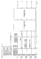
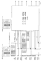
- FIG. 72 is a diagram showing a cell A of a wireless LAN including one wireless base station AP1 and three wireless terminals STA11 to STA13.
- the wireless base station AP1 and the wireless terminal STA13 conform to the IEEE 802.11ac standard, and support three types of transmission / reception bandwidths of 20 MHz, 40 MHz, and 80 MHz.
- the wireless terminal STA11 conforms to the IEEE 802.11a standard
- the wireless terminal STA12 conforms to the IEEE 802.11n standard, and supports 20 MHz and 20 MHz and 40 MHz transmission / reception bandwidths, respectively.
- FIG. 73 is a time chart showing the timing of frame transmission when the transmission right acquisition wireless communication station transmits a plurality of frames to another wireless communication station within the TXOP.
- the horizontal axis indicates time.
- the description of (STA11) or the like in the frame indicates the destination wireless communication station, and, for example, (STA11) indicates that the destination is the wireless terminal STA11.
- NAV (RTS) indicates that NAV is set after receiving an RTS not addressed to the own station.
- the wireless base station AP1 and the wireless terminals STA11 to STA13 exist as wireless communication stations, the wireless base station AP1 accommodates data addressed to the wireless terminals STA11 to STA13, and transmits frames addressed to the wireless terminals STA11 to STA13.
- the radio base station AP1 acquires TXOP, and transmits data on the 80 MHz channel to the radio terminal STA13 which can use the largest bandwidth among the destination terminals. After completing the data communication with the wireless terminal STA13, the wireless base station AP1 transmits data to the wireless terminal STA12 which can use the second largest bandwidth among the destination terminals, and finally, the smallest bandwidth among the destination terminals Transmits data to the wireless terminal STA11 that can use
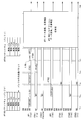
- the wireless base station AP1 executes CSMA / CA, and signals transmitted from other wireless communication stations over a predetermined sensing period and random backoff time are transmitted. Confirm that it is not detected and acquire the transmission right (TXOP). Since the radio base station AP1 has acquired the transmission right, it becomes a transmission right acquisition radio communication station (TXOP Holder), and transmits a frame.
- TXOP Holder transmission right acquisition radio communication station
- the radio base station AP1 sends an RTS (Request to Send: transmission request) frame as a start frame indicating the start of the frame sequence to the radio terminal STA13 that can use the largest band among the destination terminals to transmit data.
- RTS Request to Send: transmission request
- the wireless terminal STA13 returns a CTS (Clear To Send: transmission permission) frame to the wireless base station AP1 because the destination of the received RTS frame is the own station and the transmission stop period is not set in the own station. (Time t 112 ). As a result, the wireless terminal STA13 notifies the wireless base station AP1 that it is ready to receive data.
- CTS Call To Send: transmission permission
- the sustained use period information included in the RTS frame indicates The period is set to the NAV period (transmission stop period) so that frame transmission is not performed within the corresponding NAV period. Further, the reception of the RTS frame from the wireless base station AP1 detects that the TXOP period (usable transmission right period) has been started, and the wireless terminals STA11 to STA13 perform the wireless communication for obtaining the transmission right of the wireless base station AP1. It memorizes that it is a station (TXOP Holder).
- the wireless base station AP1 transmits a frame addressed to the wireless terminal STA13 (time t 113 ).
- the wireless terminal STA13 Upon correctly receiving the frame addressed to the wireless terminal STA13, the wireless terminal STA13 sends back a BA (Block ACK) frame (or an ACK (Acknowledgement: acknowledgment) frame) to the wireless base station AP1 (time t 114 ). Finish sending and receiving.
- BA Block ACK
- ACK Acknowledgement: acknowledgment
- the wireless base station AP1 transmits an RTS frame whose destination is the wireless terminal STA12 in order to transmit data addressed to the wireless terminal STA12 which can use the second largest band among the destination terminals (time t 115 ).
- the wireless terminal STA12 has its NAV set in its own station, it has received a frame from the TXOP Holder, so it returns a CTS frame addressed to the transmission right acquisition wireless communication station AP1 (time t 116 ).
- the wireless terminal STA11 and the wireless terminal STA13 set the NAV period by receiving the RTS frame addressed to the other wireless terminal. If the NAV period has already been set, the NAV value is updated.
- the wireless base station AP1 Upon correctly receiving the CTS frame from the wireless terminal STA12, the wireless base station AP1 transmits a frame addressed to the wireless terminal STA12 (time t 117 ).
- the wireless terminal STA12 sends back a BA frame (or an ACK frame) to the wireless base station AP1 (time t 118 ), and ends transmission and reception of the frame.
- the wireless base station AP1 transmits an RTS frame whose destination is the wireless terminal STA11 in order to transmit data addressed to the wireless terminal STA11 in which the smallest band can be used among the destination terminals (time t 119 ). Since the wireless terminal STA11 receives the RTS frame from the wireless base station AP1 that is the transmission right acquisition wireless communication station, the CTS frame is sent back to the transmission right acquisition wireless communication station regardless of whether it is within the NAV period Time t 120 ).
- the wireless terminal STA12 and the wireless terminal STA13 have received an RTS frame not addressed to the own station, they set the NAV period. If the NAV period has already been set, the NAV value is updated.
- the wireless base station AP1 Upon properly receiving the CTS frame from the wireless terminal STA11, the wireless base station AP1 transmits a frame addressed to the wireless terminal STA11 (time t 121 ).
- the wireless terminal STA11 correctly receives the frame from the wireless base station AP1
- the wireless terminal STA11 sends back a BA frame (or an ACK frame) to the wireless base station AP1 (time t 122 ) to complete transmission and reception of the frame.
- the above explanation is an example of a frame sequence in the case of applying the MAC protection method by RTS / CTS exchange before transmitting data, but it is possible to transmit data immediately after acquiring the access right without exchanging RTS / CTS. It is also possible to transmit a frame for
- the above description is an example in which frames are transmitted to a plurality of terminals in the same TXOP section. As described above, frames can be transmitted to a plurality of terminals within the range not exceeding the upper limit of TXOP defined in the IEEE 802.11 standard. Also, in this case, communication can not be performed using a channel width larger than the channel width used once in this TXOP period.
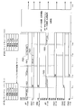
- the wireless terminal STA11 can use channel 1 (CH1)
- the wireless terminal STA12 can use CH1 and CH2
- the wireless terminal STA13 can use CH1 to CH4.
- FIG. 74 is a diagram showing channel bandwidths used for data transmission between the wireless base station AP1 and the wireless terminals STA11 to STA13. Since the wireless terminal STA11 can use only 20 MHz, the wireless base station AP1 communicates with the wireless terminal STA11 using channel 1 (CH1).
- CH1 channel 1
- Non-Patent Document 3 defines a unit channel that must be used regardless of the transmission bandwidth when performing communication in a cell configured with an access point and a terminal station, and this is a primary channel (Primary channel (Primary channel) Channel) is called.
- a channel that is used when performing communication but is not the primary channel is a secondary channel (Secondary Channel), or in Non-Patent Document 2, a secondary x MHz channel (Second x MHz Channel, x is any of 20, 40, 80)
- the secondary channel any unit channel which is not the primary channel among all the bands used by the cell will be referred to as the secondary channel.
- An example of the primary channel and the secondary channel when the unit channel is 20 MHz and the entire band used by the cell is 80 MHz is shown in FIG.
- FIG. 75 shows an example in which three secondary channels exist.
- the wireless terminal STA12 can handle up to 40 MHz, communication between the wireless base station AP1 and the wireless terminal STA12 is performed on the 20 MHz primary channel and the 20 MHz (secondary channel) adjacent to the primary channel (that is, on CH1 and CH2) . Further, since the wireless terminal STA13 can handle up to 80 MHz, communication between the wireless base station AP1 and the wireless terminal STA13 is performed on the primary channel and the three secondary channels.
- the transmittable / receivable bandwidths of the wireless base station AP1 and the wireless terminals STA11 to STA13 are different, a part of the entire frequency band that the wireless base station AP1 can handle may not be used. is there. For example, when the wireless base station AP1 communicates with the wireless terminal STA11, the channels CH2 to CH4 become free, and when the wireless base station AP1 communicates with the wireless terminal STA12, the channels CH3 to CH4 become free.
- the capacity of the radio base station AP1 is not fully utilized, and the frequency resources are not used effectively, and there is a problem that the throughput of the entire system is reduced or the service quality is deteriorated.
- the present invention has been made in view of such circumstances, and it is an object of the present invention to provide a wireless communication system and a wireless communication method capable of improving the throughput of wireless communication by effective use of frequency resources.
- carrier sensing is possible between a first wireless base station performing communication with a wireless terminal by orthogonal frequency division multiple access in a first cell, and the first wireless base station, Wireless communication system in which a wireless terminal and a second wireless base station performing communication by orthogonal frequency division multiple access in a cell cooperate with each other, and the first wireless base station is configured to transmit data to be transmitted.
- Access right acquisition means for acquiring an access right when it occurs, and a use permission for transmitting to the second radio base station permission to use a channel not used in the first cell during a period when the access right is acquired
- a wireless communication system comprising: transmitting means, the second wireless base station comprising communication means for communicating with the wireless terminal in the second cell using the channel for which the use permission has been obtained Is Temu.
- the present invention is the wireless communication system, wherein the use permission transmitting means transmits the use permission of the unused secondary channel using a primary channel.
- the present invention is the wireless communication system, wherein the use permission transmission means transmits the use permission of the unused secondary channel using all the channels.
- the present invention is the wireless communication system, wherein the use permission transmission means transmits the use permission of a channel for which transmission permission has not been returned in response to a transmission request transmitted using all the channels.
- the present invention is the wireless communication system, wherein the use permission transmission means transmits the use permission of a channel not to be used based on a transmission permission reply in response to a transmission request transmitted using all channels.
- the present invention is the wireless communication system, wherein the use permission transmission means transmits the use permission of the secondary channel when the wireless terminal to be communicated is a terminal to which orthogonal frequency division multiple access can not be applied.
- the use permission transmission means transmits the use permission of the secondary channel, and the second permission permission is obtained
- the wireless terminal under control of the wireless base station is a wireless communication system which returns a transmission permission according to an available channel.
- the first wireless base station determines a channel to which the use permission can be given and transmits data after transmitting the use permission using the primary channel by the use permission transmitting means. It is a wireless communication system.
- the first wireless base station determines a channel to which the usage permission can be granted and transmits data after the usage permission transmission means transmits the usage permission using all the channels. It is a wireless communication system to perform.
- the first wireless base station determines a channel to which the usage permission can be granted, transmits the usage permission using the primary channel by the usage permission transmitting means, and transmits the usage permission.
- a wireless communication system that transmits data after receiving an acknowledgment.
- the first wireless base station determines a channel to which the usage permission can be granted, transmits the usage permission using all the channels by the usage permission transmitting means, and the usage permission A wireless communication system for transmitting data after receiving an acknowledgment for
- carrier sensing is possible between a first wireless base station performing communication with a wireless terminal by orthogonal frequency division multiple access in a first cell, and the first wireless base station
- a radio communication system in which a radio terminal and a second radio base station performing communication by orthogonal frequency division multiple access in a cell cooperate with each other, and the radio terminal in the first cell is the orthogonal frequency First data receiving means for receiving data transmitted from the first wireless base station on different channels for different data addressed to a plurality of wireless terminals by split multiple access, and data correctly by the first data receiving means
- a first response confirmation transmission means for transmitting a response confirmation, and the wireless terminal in the second cell receives the permission of use from the first wireless base station.
- a second data receiving means for receiving data transmitted from the second wireless base station by the orthogonal frequency division multiple access, and a response confirmation when the data can be correctly received by the second data receiving means It is a radio
- the present invention is a wireless communication system in which the response confirmation sent back by each of the first response confirmation transmission means and the second response confirmation transmission means is sent back using uplink orthogonal frequency division multiple access.
- the present invention is a wireless communication system, wherein the second wireless base station includes an access right acquisition unit that acquires an access right, and transmits the response confirmation after acquiring the access right.
- the first response confirmation is transmitted using a primary channel, and It is a radio
- carrier sensing is possible between a first wireless base station performing communication with a wireless terminal by orthogonal frequency division multiple access in a first cell, and the first wireless base station, A wireless communication method performed by a wireless communication system in which a wireless terminal and a second wireless base station performing communication by orthogonal frequency division multiple access in a cell cooperate with each other in the cell, wherein the first wireless base station is An access right acquisition step of acquiring an access right when data to be transmitted occurs; and a permission of use of a channel not used in the first cell in a period in which the first radio base station acquires the access right A use permission transmission step of transmitting to the second wireless base station; and the second wireless base station using the channel for which the use permission has been granted in the second cell. It is a wireless communication method and a communication step of performing communication with the terminal.
- carrier sensing is possible between a first wireless base station performing communication with a wireless terminal by orthogonal frequency division multiple access in a first cell, and the first wireless base station, Wireless communication method performed by a wireless communication system in which a wireless terminal and a second wireless base station performing communication by orthogonal frequency division multiple access in a cell cooperate with each other, and the wireless terminal in the first cell
- a first data receiving step of receiving data transmitted from the first wireless base station on different channels for different data addressed to a plurality of wireless terminals by the orthogonal frequency division multiple access A first response confirmation transmission step of transmitting a response confirmation when the wireless terminal in the second data reception step correctly receives data, and the wireless terminal in the second cell
- the present invention by transmitting data using orthogonal frequency division multiple access (OFDMA) to a plurality of wireless communication stations, the effect of improving the system throughput by improving the frequency of use of the secondary channel can be obtained.
- OFDMA orthogonal frequency division multiple access
- FIG. 7 is a diagram illustrating classification of MAC protection. It is a time chart which shows the frame sequence in case the number of wireless terminals which respond is 1, and the wireless terminal which replies CTS is 11ax wireless terminal (OFDMA correspondence).
- the number of wireless terminals that respond is 2 or more, the RTS frame is sent to each wireless terminal, and the legacy terminals are included in the wireless terminals that return CTS, and the transmission bandwidth of the second and subsequent RTS frames is It is a time chart which shows a frame sequence in the case of setting below the bandwidth checked by the CTS frame received immediately before.
- the number of wireless terminals that respond is two or more, and the wireless terminals that return CTS are all 11ax wireless terminals, and the CTS frame is a time chart showing a frame sequence when transmitting by OFDMA.
- the number of wireless terminals that respond is two or more, and all wireless terminals that return CTS are 11ax wireless terminals
- the CTS frame is a time chart showing a frame sequence when transmitting by MU-MIMO. It is a figure which shows the format of the CTS frame in 11a / n / ac. It is a figure which shows the format of the transmission frame at the time of four radio
- the CTS frame is a time chart showing a frame sequence in the case of transmitting by OFDMA when the number of wireless terminals to respond is two or more, and a legacy terminal is also included in the wireless terminals that return CTS.
- the frame sequence in the case where all the wireless terminals to return CTS are 11ax wireless terminals It is a time chart which shows.
- a time indicating a frame sequence when all wireless terminals that return CTS are 11ax wireless terminals It is a chart.
- An ECTS frame is a time chart which shows a frame sequence in the case of transmitting by OFDMA, when the number of wireless terminals which respond is two or more, and the wireless terminals which return CTS are all 11ax wireless terminals.
- 16 is a time chart showing a frame sequence in a case where OFDMA + MU-MIMO is used, the data destinations are all 11ax wireless terminals, and the data lengths are different. It is a figure which shows the classification of response confirmation. It is a time chart which shows a frame sequence in case the number of terminals which respond is 1, the wireless terminals which return ACK are all 11ax terminals, and the channel used is a secondary channel. It is a time chart which shows a frame sequence in case the number of terminals which respond is two or more, and the use channel of response confirmation is a primary channel. It is a time chart which shows the frame sequence in case the number of terminals to respond is two or more, and the channel used for response confirmation also uses a secondary channel.
- FIG. 7 illustrates a frame sequence of MAC protection that can be combined. It is a time chart which shows the example of the frame sequence which combined the frame sequence. It is a time chart which shows another example of a frame sequence which combined a frame sequence.
- wireless communication station transmits multiple flame
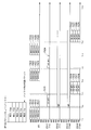
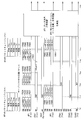
- FIG. 1 is a block diagram showing the configuration of the wireless base station and the wireless terminal in the embodiment, and a diagram showing the configuration of the network.
- a feature of the wireless communication system in the present embodiment is that the wireless communication station that has become the transmission right acquiring wireless communication station addresses data to a plurality of wireless communication stations on a plurality of channels using orthogonal frequency division multiple access (OFDMA). The point is to send.
- the cell A of the wireless communication system shown in FIG. 1 includes a wireless base station AP1 which is a wireless communication station, and five wireless terminals STA11 to STA15.
- the wireless base station AP1 and the wireless terminals STA14 and STA15 are wireless communication stations compatible with OFDMA, and it is assumed that a maximum transmission / reception bandwidth of 80 MHz is supported.
- the STA 13 conforms to the IEEE 802.11ac standard, and supports three types of transmission / reception bandwidths of 20 MHz, 40 MHz and 80 MHz.
- the wireless terminal STA11 conforms to the IEEE 802.11a standard
- the wireless terminal STA12 conforms to the IEEE 802.11n standard, and supports 20 MHz and 20 MHz and 40 MHz transmission / reception bandwidths, respectively.
- an IEEE 802.11ax wireless terminal (hereinafter referred to as an 11ax wireless terminal) has a function capable of realizing the present embodiment in addition to the function possessed by the IEEE 802.11ac compliant wireless communication station. It is a generic term for wireless communication stations. Further, the legacy terminal is a generic term for wireless communication stations compliant with the existing standards (IEEE802.11a, IEEE802.11n, IEEE802.11ac) not having the function defined in the present specification.
- the wireless terminal conforming to the IEEE802.11a standard is 11a wireless terminal
- the wireless terminal conforming to the IEEE802.11n standard is 11n wireless terminal
- the wireless terminal conforming to the IEEE802.11ac standard is 11ac wireless It is called a terminal.
- the idle channel is effectively used by causing a wireless communication station that transmits and receives data in an IEEE 802.11 wireless LAN system to perform orthogonal frequency division multiple access (OFDMA) operation.
- OFDMA technology is used in the IEEE 802.11 wireless LAN, for example, when the wireless base station AP1 transmits data to the wireless station STA11 using channel 1 in the wireless communication system shown in FIG. 1, the remaining channels 2 to 4 are used. Data destined for other wireless communication stations (eg, wireless terminal STA14 capable of OFDMA) can be transmitted. Similarly, when the wireless base station AP1 transmits data using the wireless terminal STA12 and channels 1 and 2, the remaining channels 3 and 4 are used to transmit data to another wireless communication station (for example, the wireless terminal STA14). Can be sent.
- OFDMA orthogonal frequency division multiple access
- a guard band (Guard band: GB) is provided between the channels without using OFDMA in all available bands to avoid interference between adjacent channels, and a plurality of radios are simultaneously set using the remaining bands.
- the frame may be transmitted to the communication station. For example, when a guard band of 20 MHz is provided, when the wireless base station AP1 transmits a frame to the wireless terminal STA11 using channel 1, channel 2 is used as a guard band and the remaining wireless channels 3 and 4 are used to transmit other wireless signals. The frame is transmitted to the communication station (for example, the wireless terminal STA14). Similarly, when the wireless base station AP1 transmits a frame using the wireless terminal STA12 and channels 1 and 2, channel 3 is used as a guard band and another wireless communication station (for example, wireless terminal STA14) using channel 4 Send a frame to
- a destination wireless communication station to which data is transmitted from the wireless communication station that has acquired the access right on the primary channel is called a primary wireless communication station (Primary STA).
- the terminal which transmits data by OFDMA using the whole or a part of the band not including the primary channel (the wireless terminal STA14 in the above example) is a secondary wireless communication station It is called Secondary STA).
- Secondary STA Although only one primary radio communication station exists in the IEEE 802.11a standard and the IEEE 802.11n standard, a plurality of primary radio communication stations may exist in the IEEE 802.11 ac standard (draft) using MU-MIMO. is there.
- the transmission right acquisition wireless communication station can transmit data to the primary wireless communication station using a plurality of channels.
- the primary wireless communication station is a terminal compliant with the IEEE 802.11a standard, only one 20 MHz channel (primary channel) is used for data transmission, but the primary wireless communication station is the IEEE 802.11n standard or the IEEE 802.11 ac
- a standard compliant terminal can transmit and receive data using up to two and eight 20 MHz channels, respectively.
- a channel group including a primary channel used for communication with a primary wireless communication station is referred to as a primary channel group (Primary Channels).
- the transmission right acquisition wireless communication station can transmit data to the secondary wireless communication station using one or more channels within the range that does not interfere with the primary wireless communication station.
- a channel group not including the primary channel used for communication with the secondary wireless communication station is called a secondary channel group (Secondary Channels).
- a secondary channel group may be used as needed.
- MAC protection such as RTS / CTS may be implemented.
- the length of the communication period with the secondary wireless communication station is limited to the communication period with the primary wireless communication station (a so-called TXOP period obtained and set according to the IEEE 802.11 standard).
- the radio base station AP1 shown in FIG. 1 includes a radio communication unit 11, a transmission right acquisition unit 12, an information management unit 13, and a control unit 14.
- the wireless terminal STA11 shown in FIG. 1 has the same configuration as the wireless base station AP1, and includes a wireless communication unit 21, a transmission right acquisition unit 22, an information management unit 23, and a control unit 24.
- the wireless terminals STA12 to STA15 are similar in configuration to the wireless terminal STA11, although the functions such as the used bandwidth and the presence / absence of support for OFDMA transmission are different, so the detailed illustration is omitted in FIG.
- the wireless communication unit 11 transmits and receives frames with other wireless communication stations (wireless terminals STA11 to STA15) using a predetermined frequency band.
- the control unit 14 requests the transmission right acquisition unit 12 to acquire the transmission right (TXOP).
- the information management unit 13 stores information.
- the control unit 14 controls transmission and reception of frames performed by the wireless communication unit 11 based on the transmission right acquisition state from the transmission right acquisition unit 12 and the information recorded in the information management unit 13.
- the wireless communication unit 21 transmits and receives frames with another wireless communication station (wireless base station AP1) using a predetermined frequency band.
- the control unit 24 requests the transmission right acquisition unit 22 to acquire the transmission right (TXOP).
- the information management unit 23 stores information.
- the control unit 24 controls transmission and reception of frames performed by the wireless communication unit 21 based on the transmission right acquisition state from the transmission right acquisition unit 22 and the information recorded in the information management unit 23.
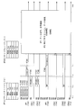
- FIG. 2 is a flowchart showing the transmission processing operation of the radio base station AP1 shown in FIG.
- the control unit 14 requests the transmission right acquisition unit 12 to acquire the transmission right, and the transmission right
- the acquisition unit 12 confirms that a signal transmitted from another wireless communication station is not detected for a predetermined sensing period and a random backoff time via the wireless communication unit 11, and confirms that the signal is in an idle state. Is acquired (step S101).
- control unit 14 stores in the information management unit 3 whether the destination wireless communication station (so-called primary wireless communication station) of the frame to be transmitted can transmit and receive signals with the same bandwidth as the own wireless communication station. The determination is made with reference to the information being processed (step S102).
- step S102 when it is determined in step S102 that the primary wireless communication station is a wireless communication station having the ability to receive signals in the same bandwidth as the own wireless communication station (step S102: NO), the control unit 14 Requests the wireless communication unit 11 to transmit a frame, and in response to the request, the wireless communication unit 11 performs frame transmission as usual (step S105) and finishes the transmission.
- control unit 14 uses OFDMA. It is then determined whether data can be transmitted to the secondary wireless communication station (step S103). As a result of this determination, when it is not possible to implement OFDMA (step S103: NO), the control unit 14 requests the wireless communication unit 11 to transmit a frame, and the wireless communication unit 11 responds to this request. The frame transmission / reception is performed as it is (step S105), and the transmission is finished.
- step S103 when there is data to be transmitted to the secondary radio communication station and it is possible to implement OFDMA (step S103: YES), the control unit 14 performs the transmission and reception of data on the primary channel group with the primary radio communication station.
- a secondary wireless communication station capable of transmitting and receiving data in a larger band and all channels available in the wireless communication station or some channels according to transmission power, MCS used for transmission, etc.
- the RTS or CTS frame is exchanged or the CTS-to-Self frame is transmitted using the non-HT duplicate mode via the wireless communication unit 11, and MAC protection is applied (step S104).
- control unit 14 requests the wireless communication unit 11 to transmit a frame, and in response to the request, the wireless communication unit 11 transmits a frame to the primary wireless communication station on the primary channel group, and A frame is transmitted to the secondary wireless communication station on the secondary channel group, and the TXOP period ends (step S106).
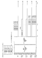
- FIG. 3 is a time chart showing a frame sequence when the transmission right acquisition wireless communication station (wireless base station AP1) transmits a plurality of frames to another wireless communication station (wireless terminal).
- the horizontal axis represents time
- the vertical axis of each wireless communication station represents a channel used for data transmission.
- Only the relevant wireless terminals (the wireless terminals STA11 to STA14 in FIG. 3) are illustrated in the drawings showing the following frame sequences. Further, the description of “(STA14)” and the like in the frame indicates the destination wireless communication station, and “(STA14)” indicates that the destination is the wireless terminal STA14.
- the wireless base station AP1 performs CSMA / CA (carrier sense), and another wireless communication station (wireless communication station (wireless communication station) is performed over a predetermined sensing period and random backoff period. It confirms that the signal transmitted from the terminals STA11 to STA15) is not detected, and acquires the transmission right (TXOP). Since the radio base station AP1 has acquired the transmission right, it becomes a transmission right acquisition radio communication station, and transmits a frame.
- CSMA / CA carrier sense
- wireless communication station wireless communication station
- the channel usable by the wireless terminal STA11 is only channel 1 (primary channel).
- the RTS frames F1 to F4 are transmitted as start frames addressed to the wireless terminal STA14 capable of communication in many channels (time t 111 ).
- the radio base station AP1 transmits RTS frames to all 20 MHz wide channels that can use signals in the Duplicate mode defined by the IEEE 802.11n standard or the 802.11ac standard, that is, a 20 MHz channel bandwidth (here Transmit on four 20 MHz wide channels).
- the wireless terminals STA11 to STA14 receive the RTS frame transmitted from the wireless base station AP1. Having received the RTS frame not addressed to the wireless terminals STA11 to STA13, the wireless terminals STA11 to STA13 set the period indicated by the sustained use period information (Duration) included in the received RTS frame as the NAV period, and Do not send.
- the wireless terminals STA11 to STA13 also store in the information management unit 23 that the source terminal (wireless base station AP1) of the received RTS frame is the wireless communication station that has acquired the TXOP.
- the wireless terminal STA14 Upon receiving the RTS frame from the wireless base station AP1, the wireless terminal STA14 detects that the destination of the received RTS frame is the own apparatus, and the NAV is not set or a signal is detected for a predetermined period.
- the CTS frames F5 to F8 are sent back to the radio base station AP1 on a channel that has not been received (time t 112 ).
- the wireless base station AP1 Upon receiving the CTS frame from the wireless terminal STA14, the wireless base station AP1 transmits frames F9 to F11 addressed to the wireless terminals STA11 and STA14 using OFDMA (time t 113 ).
- the wireless base station AP1 transmits the corresponding frame to the primary wireless communication station using the entire band available in the primary wireless communication station. In the remaining band, guard bands are provided as needed, and the frame of STA 14 is transmitted to STA 14 on the remaining channel.
- a frame is transmitted on channel 1 to wireless terminal STA11, channel 2 is set as a guard band, and a frame is transmitted to wireless terminal STA14 on channels 3 to 4.
- the wireless terminal STA11 Upon correctly receiving the frame addressed to the wireless terminal STA11 from the wireless base station AP1, the wireless terminal STA11 transmits a BA frame F12 (or an ACK frame) to the wireless base station AP1 (time t 114 ), and ends transmission and reception of the frame. At this time, the wireless terminal STA11 sends back BA on the same channel as the signal received from the wireless base station AP1.
- a BA frame F12 or an ACK frame
- the wireless terminal STA14 when the wireless terminal STA14 correctly receives the frame addressed to itself from the wireless base station AP1, the wireless terminal STA14 transmits BA frames F13 and F14 (or ACK frame) to the wireless base station AP1 (time t 114 ). Finish sending and receiving. The wireless terminal STA14 sends back BA on the same secondary channel group as the signal received from the wireless base station AP1.
- the conventional RTS / CTS exchange was used to block access by other terminals, but in the RTS / CTS exchange described above, blocking access by other terminals and using OFDMA for each wireless terminal It is possible to confirm the bandwidth that should be.
- the description of the modification will be divided into a frame sequence when performing MAC protection, a frame sequence when performing data transmission, and a frame sequence when performing response confirmation.
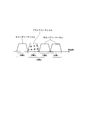
- FIG. 4 is a diagram showing the classification of MAC protection.
- MAC protection (whose identification name is A) uses RTS when it is used (as identification name and A1) and enhanced RTS (which is called ERTS: Enhanced RTS). It can be classified into cases (the identification name is A2).
- RTS RTS when it is used
- ERTS Enhanced RTS
- FIG. 5 is a time chart showing a frame sequence in the case where the number of wireless terminals responding is 1 and the wireless terminal returning CTS is an 11ax wireless terminal.
- the head packet of the buffer is addressed to the 11a wireless terminal.
- the non-HT Duplicate mode is a mode in which a 20 MHz signal is replicated on the frequency axis and transmitted in parallel, and the entire signal can be decoded by receiving only an arbitrary 20 MHz.
- the Dynamic BW mode is a mode in which CTS is returned on a channel that is not busy among the channels notified by RTS.
- the wireless terminal STA14 sends back CTS frames F25 to F28 using all the channels (time t 112 ). This frame sequence is equivalent to the frame sequence shown in FIG.
- FIG. 6 shows the case where the number of responding wireless terminals is two or more, and all the wireless terminals that transmit RTS frames using the same bandwidth to each wireless terminal and return CTS are OFDMA compatible (11ax) terminals It is a time chart which shows the frame sequence of.
- the RTA is used to inquire the channel usage status of the OFDMA compatible wireless terminal, resources are reserved in a larger band, and resource reallocation is performed to other terminals.
- the radio base station AP1 always transmits a frame (fixed bandwidth) on the channel set used for the first frame transmission.
- FIG. 6 shows a frame sequence in the case where the number of responding terminals is two or more, but only two responding wireless terminals are illustrated. The same frame sequence can be applied even when the number of terminals to respond is three or more. The same applies to a frame sequence in which the number of responding terminals in the following description is two or more.
- the radio base station AP1 transmits RTS frames F31 to F34 (non-HT Duplicate mode, dynamic BW mode) to all the channels of 20 MHz for the 11ax radio terminal STA14 to reserve a larger band (time t 111). ).
- the wireless terminal STA14 sends back CTS frames F35 to F37 (time t 112 ).
- the radio base station AP1 has received CTS in a part of the band (for example, the interference of CH4 is detected in the radio base station STA14), RTS in the entire band is addressed to another radio terminal (here, the radio terminal STA15) again
- the frames F38 to F41 are transmitted (time t 113 ).
- the radio terminal STA15 performs the reply of the CTS frame F42, F43 (time t 114).
- the number of wireless terminals that respond is 2 or more, transmits an RTS frame using the same bandwidth to each wireless terminal, and transmits CTS as a response to the wireless terminal.
- the frame sequence will be described in the case where no legacy terminals are included (A1-3 shown in FIG. 4).
- the number of wireless terminals that respond is 2 or more, and the wireless terminals that transmit RTS frames using the same bandwidth to each wireless terminal and return CTS include legacy terminals that are not compatible with OFDMA. It is a time chart which shows the frame sequence of the case.
- the wireless base station AP1 first sends RTS frames F51 to F54 to the 11ax wireless terminal STA14 using all channels for every 20 MHz (non -HT Duplicate mode, dynamic BW mode) transmit and reserve a larger bandwidth (time t 111 ).
- the wireless terminal STA14 sends back CTS frames F55 to F57 (time t 112 ).
- the radio base station AP1 transmits RTS frames F58 to F61 for confirming whether data may be transmitted to the 11a radio terminal STA11 (time t 113 ).
- the corresponding terminals 11e, 11s, and 11n also store the TXOP Holder when setting the NAV, so that when there is a call from the TXOP Holder, the response is returned even if the NAV is set.
- the wireless terminal STA11 performs reply CTS frame F 62 (time t 114).
- RTS frames are transmitted to the secondary wireless communication station on all channels, and after returning CTS, RTS / CTS exchange is performed again for the primary wireless communication station.
- the primary wireless communication station can use only a part of the channels (in this example, only CH1 can be used)
- the wireless base station AP1 which is the transmission right acquiring communication station, can also use RTS on all channels for the primary wireless communication station. To prevent the third wireless communication station from interrupting the secondary channel.
- FIG. 8 is a time chart showing a modification of the frame sequence shown in FIG. 8 is for transmitting RTS on all channels to legacy terminals first.
- the radio base station AP1 transmits RTS frames F71 to F74 (non-HT Duplicate mode) to the 11a radio terminal STA11 using all channels of every 20 MHz, and reserves a larger band (time t 111 ).
- the wireless terminal STA11 sends back a CTS frame F75 (time t 112 ).
- RTS frames F76 to F79 are transmitted (non-HT duplicate, dynamic mode) to the 11ax wireless terminal STA14, and it is checked whether there is a secondary channel receivable by OFDMA (time t 113 ).
- the wireless terminal STA14 sends back CTS frames F80 to F82 (time t 114 ).
- the other wireless communication stations transmit RTS on all channels (fixed bandwidth mode) used for the previous RTS frame transmission. It is possible to reconfirm whether it is possible to transmit a frame on a channel that has not been transmitted and that has not received a CTS reply.
- FIG. 9 is a time chart showing a frame sequence in the case where the number of wireless terminals responding to an RTS frame transmitted by OFDMA is two or more, and a CTS frame is returned at each predetermined time.
- This is a conventional RTS-based scheduling type CTS reply, and upon receiving the RTS on the secondary, the 11ax wireless terminal returns a CTS after a CTS + 2 SIFS period.
- the radio base station AP1 sets the primary channel as the RTS frame F91 addressed to the legacy terminal, sets the RTS frames F92 to F94 addressed to the 11ax radio terminal to the secondary channel, and transmits the RTS frame by OFDMA (time t 111 ).
- the wireless terminal STA11 sends back a CTS frame F95
- the 11ax wireless terminal STA14 determines from the RTS frame of the primary channel whether or not the RTS frame addressed to the 11ax wireless terminal exists in the secondary channel.
- CTS frames F96 to F98 are sent back.
- FIG. 10 shows the RTS frame format.
- the channel bandwidth in which the RTS frame is copied and the static / dynamic BW mode are notified using Scrambler Initialization of the radio frame header and the TA of the payload part.
- the Scrambler Initialization section is set to all 0 in the 11a / n radio communication station and to 0 in the case where the head of the TA is 0 in the 11ac radio communication station.
- the head of TA is 1, according to Table 1, RTS bandwidth and static / dynamic BW are notified.
- B1-B3 of the Scrambler Initialization unit is used as an example of a method of notifying whether or not the RTS frame different from the primary channel is transmitted by OFDMA to the secondary channel using the RTS of the primary channel.
- the head (Individual / Group bit) of TA when the head (Individual / Group bit) of TA is 0, all are set to 0. If the start of TA is 1, it is notified whether the RTS bandwidth and Static / Dynamic BW and RTS frame of the secondary channel are different from those of the primary channel according to the following format. For example, in the case of 80 MHz, the expansion shown in Table 2 is performed.
- a legacy terminal that does not support the OFDMA communication of the RTS frame decodes only the RTS frame of the primary channel and sets the NAV without referring to the information of B0 to B3, so backward compatibility can be ensured.
- the 11ax radio terminal that received the RTS frame whose TA start address is 1 on the primary channel refers to B1-3 of the Scrambler Initialization section, and does the RTS frame different from the primary channel exist in the secondary channel? It is determined whether or not. Then, if it is present, information on the secondary channel is also decoded together, and if it is an RTS frame addressed to the own station, a CTS frame is sent back using all or part of the channel.
- an RTS frame is transmitted using the primary channel to request a CTS frame, and an OFDMA compatible destination station using the secondary channel is requested.
- a CTS frame it is possible to check whether the frame can be transmitted to all the destination stations in a single RTS frame and reduce the overhead of the wireless channel.
- the number of wireless terminals that respond is 2 or more, transmits an RTS frame to each wireless terminal, and all the wireless terminals that return CTS are 11ax wireless terminals, and the second and subsequent ones.
- a frame sequence in the case of setting the transmission bandwidth of the RTS frame below the bandwidth confirmed in the CTS frame received immediately before (A1-4 shown in FIG. 4) will be described.
- the number of wireless terminals that respond is two or more, and all the wireless terminals that transmit RTS frames to each wireless terminal and return CTS are 11ax wireless terminals, and the transmission band of the second and subsequent RTS frames
- the radio base station AP1 transmits RTS frames F101 to F104 (non-HT Duplicate mode, dynamic BW mode) to the 11ax radio terminal STA14 using all channels of every 20 MHz to reserve a larger band ( Time t 111 ).
- the wireless terminal STA14 sends back CTS frames F105 to F107 (time t 112 ).
- the radio base station AP1 determines that the channel without CTS reply is busy, and transmits RTS frames F108 to F110 so as not to transmit RTS on the channel that becomes busy (time t 113 ).
- the radio terminal STA15 do reply of the CTS frame F111 (time t 114).
- the wireless base station AP1 transmits the next RTS frame only on channels 1 to 3. That is, the RTS frame is transmitted again to the different wireless terminal STA15 only on the channel with the CTS reply without using the channel without the CTS reply.
- the number of wireless terminals responding is two or more, the RTS frame is transmitted to each wireless terminal, and the wireless terminals returning CTS include legacy terminals, and two A frame sequence in the case where the transmission bandwidth of the RTS frame after the eye is set to be equal to or less than the bandwidth confirmed in the CTS frame received immediately before (A1-5 shown in FIG. 4) will be described.
- the number of wireless terminals that respond is two or more, and the wireless terminals that transmit RTS frames to each wireless terminal and return CTS also include legacy terminals, and the second and subsequent RTS frames are included.
- It is a time chart which shows a frame sequence in the case of setting transmission bandwidth below to the bandwidth checked by the CTS frame received immediately before. This is a frame sequence when there is a wireless communication station (legacy terminal) that is almost the same as A1-4, but can not use OFDMA.
- the wireless base station AP1 uses all channels for every 20 MHz to be addressed to the 11ax wireless terminal STA14, and RTS frames F121 to F124 (non-HT Duplicate The mode (dynamic BW mode) is transmitted, and a larger bandwidth is reserved (time t 111 ).
- the wireless terminal STA14 sends back CTS frames F125 to F127 (time t 112 ).
- the radio base station AP1 transmits RTS frames F128 to F130 for confirming whether data may be transmitted to the 11a radio terminal STA11 (time t 113 ).
- the wireless terminal STA11 sends back a CTS frame F131 (time t 114 ).
- Resource reallocation can be performed for both an OFDMA compatible destination station whose bandwidth can be variably set and a destination station of the existing standard (11a, n) whose bandwidth is fixed.
- FIG. 13 the number of wireless terminals responding is two or more, all wireless terminals returning CTS are 11ax wireless terminals, and CTS is transmitted by OFDMA (A1-6 shown in FIG. 4)
- the frame sequence of FIG. 13 is a time chart showing a frame sequence in the case where the number of wireless terminals responding is 2 or more, all wireless terminals returning CTS are 11ax wireless terminals, and CTS is transmitted by OFDMA.
- UL-OFDMA is known in the literature "K. Kim, et.
- the wireless base station AP1 refers to the channel for receiving the CTS to identify the source wireless terminal.
- the radio base station AP1 simultaneously transmits the RTS frames F143 and F144 to the radio terminal STA14 using OFDMA, and the RTS frames F141 and F142 simultaneously to the STA 15 (time t 111 ).
- each of the wireless terminals STA14 and STA15 sends back CTS frames F145 to F148 (time t 112 ).
- the RTS frame is transmitted to different wireless terminals using downlink OFDMA.
- Each of the wireless terminals STA14 and STA15 that have received the RTS frame returns a CTS using the uplink OFDMA.
- Each wireless communication station can simultaneously transmit a CTS frame because it returns a CTS only on the channel that received the RTS frame.
- FIG. 14 is a time chart showing a frame sequence in the case where the number of wireless terminals responding is 2 or more, all wireless terminals returning CTS are 11ax wireless terminals, and the CTS frame is transmitted by MU-MIMO. This is to perform CTS multiplexing using UL-OFDMA and SDMA, and since there is no field for identifying the transmission source terminal in the CTS frame, in the radio base station AP1, which radio terminal returned CTS Because the discrimination is difficult, the transmission source radio terminal is discriminated by signal processing using CSD in PHY.
- the radio base station AP1 simultaneously transmits the RTS frames F153 and F154 to the radio terminal STA14 using OFDMA and the RTS frames F151 and F152 simultaneously to the STA 15 (time t 111 ).
- each of the 11ax wireless terminals STA14 and STA15 returns CTS frames F158 to F161 and F155 to F157 on all available channels (time t 112 ).
- FIG. 15 is a diagram showing the format of a CTS frame in 11a / n / ac.
- the CTS frame shown in FIG. 15 can not simply be used for space multiplex transmission. The reason is that although L-LTF is the only part used for channel estimation, there is virtually no information for one OFDM symbol, there is no orthogonality between spatial streams, separation is not possible, and MIMO channels can not be estimated. Therefore, the subsequent payload part can not be decoded correctly.
- the header part is changed here because identification can not be performed in the header part of the Non-HT PPDU. Specifically, the VHT frame format is used.
- FIG. 16 is a diagram showing the format of a transmission frame when four wireless terminals (STAs) perform space multiplexing transmission of a CTS frame.
- VHT-SIG-A includes the following two pieces of information.
- the first information is list information of wireless terminals transmitting simultaneously or information (for example, group ID) according to the list information.
- the second information is the number and number of spatial streams transmitted by each wireless terminal.
- the wireless terminal (STA-A) has one stream (first spatial stream)
- the wireless terminal (STA-B) has one stream (second spatial stream)
- C) is one stream (third spatial stream)
- the wireless terminal (STA-D) is one stream (fourth spatial stream).
- each wireless terminal performs transmission using a prescribed pattern such that the 4 ⁇ 4 matrix for each subcarrier composed of 16 of VHT-LTF 11 to VHT-LTF 44 has an inverse matrix.
- An example corresponding to FIG. 16 is as follows.
- the radio base station estimates the channel state of MU-MIMO transmission by utilizing the VHT-LTF. Since the wireless base station can read the correspondence between the spatial stream and the wireless terminal from VHT-SIG-A, it is assumed that the payload portion does not include the source address and that the bit information is completely the same. Also, it becomes possible to determine the wireless terminal that has transmitted this CTS frame. For example, if the decoding of the third CTS frame is successful, this is considered to be a CTS frame transmitted from the wireless terminal (STA-C).
- CTS is not only set on the channel that received the RTS frame, but of all the available channels, NAV is not set, and CTS is set on all channels that have not received a signal for a predetermined period. Can reply.
- FIG. 17 is a time chart showing a frame sequence in the case of transmitting a CTS frame by OFDMA when the number of wireless terminals that respond is 2 or more, and a legacy terminal is also included in the wireless terminals that return CTS.
- the wireless base station AP1 refers to the channel for receiving the CTS to identify the source wireless terminal.
- the wireless base station AP1 sets the primary channel as the RTS frame F171 for the legacy terminal (wireless terminal STA11), and simultaneously transmits RTS frames F172 to F174 to the wireless terminal STA14 using OFDMA (time t 111 ).
- each of the wireless terminals STA11 and STA14 sends back CTS frames F175 to F178 (time t 112 ).
- RTS when transmitting RTS using OFDMA, RTS can be transmitted on the primary channel for legacy terminals that can only use smaller channels, and on the secondary channel for other terminals.
- FIG. 18 is a time chart showing a modification of the frame sequence shown in FIG. This is to perform CTS multiplexing using UL-OFDMA and SDMA, and since there is no field for identifying the transmission source terminal in the CTS frame, in the radio base station AP1, which radio terminal returned CTS Since it is difficult to determine whether the source STA is or is not, the source STA is determined by signal processing using CSD in PHY.
- the wireless base station AP1 sets the primary channel as the RTS frame F181 for the legacy terminal (wireless terminal STA11), and simultaneously transmits RTS frames F182 to F184 to the wireless terminal STA14 using OFDMA (time t 111 ).
- each of the 11ax wireless terminals STA14 and STA15 returns CTS frames F186 to F188 and F189 to F191 on all available channels, and the wireless terminal STA11 uses the primary channel to transmit a CTS frame F185. Reply (time t 112 ).
- RTS on the secondary channel can be transmitted to different secondary wireless communication stations using OFDMA.
- FIG. 19 further subdivides the case (A2) of using extended RTS (ERTS) in the MAC protection classification. The following description will be made based on the classification shown in FIG.
- FIG. 20 is a time chart showing a frame sequence in the case where the number of responding terminals is 1 and all wireless terminals returning CTS are 11ax wireless terminals. This is to return an ECTS frame (Extended CTS frame) obtained by extending a CTS frame on a secondary channel that is free even if the primary channel is busy, and transmits ECTS on a discontinuous channel.
- ECTS frame Extended CTS frame
- the radio base station AP1 transmits ERTS frames F201 to F204 to the radio terminal STA15 using all channels (time t 111 ).
- the ERTS frame includes list information of channel numbers to be used for data transmission.
- the wireless terminal STA15 sends back ECTS frames F205 and F206 on the vacant secondary channel (channel 2 and channel 4) (time t 112 ).
- the ECTS frame includes list information of available channel numbers among the channel numbers notified by ERTS.
- the extended RTS frame ERTS is defined to perform ERTS / ECTS exchange. Since legacy terminals can not decode ERTS frames, the destination of ERTS is always an OFDMA enabled wireless communication station.
- the primary channel needs to be idle as one of the conditions for returning CTS to the conventional RTS, but there is no such condition for returning ECTS to ERTS.
- the channels that have received the ERTS in order to send back ECTS on a channel that is idle at the receiving wireless terminal, it is possible to send ECTS on discontinuous multiple channels.
- FIG. 21 is a time chart showing a modification of the frame sequence shown in FIG. This is to obtain the access right if there is a vacancy in the secondary channel even if the primary channel is busy in the radio base station AP1, and perform communication only on the secondary channel, and one of the vacated secondary channels Is temporarily used as the primary channel, and further transmit ECTS over the discontinuous channel.
- the radio base station AP1 transmits ERTS frames F211 to F213 to the radio station STA15 only on the secondary channel (channels 2 to 4) (time t 111 ).
- the ERTS frame includes list information of channel numbers scheduled to be used for data transmission and a channel number temporarily used within the time set in the Duration field as a primary channel. Also, the NAV period at this time is adjusted to the primary channel.
- the wireless terminal STA15 sends back ECTS frames F214 and F215 using the secondary channels (channels 2 and 4) (time t 112 ).
- the ECTS frame includes list information of available channel numbers among the channel numbers notified by ERTS.
- the wireless terminal STA15 uses this channel as a primary channel while the primary channel is busy.
- FIG. 22 shows a case where the number of wireless terminals responding to an RTS frame transmitted by OFDMA is two or more, and all wireless terminals returning CTS frames at predetermined times are 11ax wireless terminals. It is a time chart which shows a sequence. This is to transmit ERTS to a plurality of wireless terminals using GID (group ID), and the transmission order of ECTS is notified by GID information in ERTS.
- GID group ID
- the wireless base station AP1 transmits ERTS frames F221 to F224 in order to check the channel availability in the 11ax wireless terminals (here, the wireless terminal STA14 and the wireless terminal STA15) by specifying the group ID (GID) Time t 111 ).
- the ERTS frame includes list information of channel numbers scheduled to be used for data transmission, list information (GID) of wireless terminal groups to be data transmission candidates, and ECTS reply order information.
- the wireless terminal STA14 returns ECTS frames F225 and F226 (time t 112 ), and the wireless terminal STA15 also returns ECTS frames F227 to F229 (time t 113 ).
- the ECTS frame includes, among the channel numbers notified by the ERTS, list information of available channel numbers and the address of the transmission source radio terminal.
- ERTS frames are simultaneously transmitted to a plurality of wireless communication stations using the group ID (GID) concept.
- the reply order of ECTS to this ERTS is specified in the ERTS frame.
- FIG. 23 shows the case where the number of wireless terminals that respond is 2 or more, and when transmitting RTS frames using the same fixed bandwidth to each wireless terminal, the wireless terminals that return CTS are all 11ax wireless terminals. It is a time chart which shows the frame sequence of. This is for the radio base station AP1 that has acquired the access right to transmit ERTS to a plurality of radio terminals with a fixed bandwidth.
- the wireless base station AP1 transmits ERTS frames F231 to F234 addressed to the wireless terminal STA15 (time t 111 ).
- the ERTS frame includes list information of channel numbers to be used for data transmission.
- the wireless terminal STA15 returns ECTS frames F235 to F237 (time t 112 ).
- the ECTS frame includes list information of available channel numbers among the channel numbers notified by ERTS.
- the radio base station AP1 transmits ERTS frames F238 to F241 to the radio terminal STA14 (time t 113 ).
- the wireless terminal STA14 returns ECTS frames F242 to F244 (time t 114 ).
- FIG. 24 shows a case where the number of wireless terminals that respond is 2 or more, and when transmitting an RTS frame using a variable bandwidth to each wireless terminal, the wireless terminals that return CTS are all 11ax wireless terminals. It is a time chart which shows a sequence. This is for the radio base station AP1 that has acquired the access right to transmit ERTS to a plurality of radio terminals with a variable bandwidth.
- the radio base station AP1 transmits ERTS frames F251 to F254 addressed to the radio terminal STA15 (time t 111 ).
- the ERTS frame includes list information of channel numbers to be used for data transmission.
- the radio terminal STA15 returns ECTS frames F255 to F257 (time t 112 ).
- the ECTS frame includes list information of available channel numbers among the channel numbers notified by ERTS.
- the wireless base station AP1 transmits ERTS frames F258 to F260 to the wireless terminal STA14 (time t 113 ).
- the radio terminal STA14 returns the ECTS frame F261, F262 (time t 114).
- FIG. 25 is a time chart showing a frame sequence in the case of transmitting an ECTS frame by OFDMA when the number of wireless terminals that respond is 2 or more and all the wireless terminals that return CTS are 11ax wireless terminals. This is to multiplex ECTS, and the wireless terminal returns ECTS on the linked channel.
- the radio base station AP1 transmits ERTS frames F271 to F274 to the radio terminal STA14 and the radio terminal STA15 by using OFDMA (time t 111 ).
- the ERTS frame includes list information of channel numbers to be used for data transmission.
- the wireless terminal STA14 and the wireless terminal STA15 respectively return ECTS frames F275 to F276 and F277 to F278 (time t 112 ).
- the ECTS frame includes list information of available channel numbers among the channel numbers notified by ERTS.
- the wireless terminal can determine the channel to which ECTS is returned in association with the ERTS.
- FIG. 26 is a time chart showing a modification of the frame sequence shown in FIG. This is to perform ECTS multiplexing, and ERTS transmits in Duplicate mode.
- the radio base station AP1 transmits the ERTS frames F281 to F284 by specifying the group ID (GID) (time t 111 ).
- the ERTS frame includes list information of channel numbers scheduled to be used for data transmission and list information of wireless terminals to be data transmission candidates.
- each of the wireless terminal STA14 and the wireless terminal STA15 sends back ECTS frames F285 to F288 and F289 to F292 (time t 112 ).
- This ECTS frame includes, among the channel numbers notified by ERTS, list information of available channel numbers and the address of the transmission source radio terminal.
- ERTS can be simultaneously transmitted to a plurality of wireless communication stations in Duplicate mode using the group ID concept, and information on available channels can be collected in each wireless communication station from the response. it can.
- FIG. 27 is a time chart showing another modification of the frame sequence shown in FIG. This is for multiplexing ECTS, and transmits ERTS in Duplicate mode.
- the receiving wireless terminal returns ECTS even if the primary channel is not available. This ECTS responds with UL MU-MIMO.
- the radio base station AP1 transmits an ERTS frame F301 to F304 by designating a group ID (GID) (time t 111 ).
- the ERTS frame includes list information of channel numbers scheduled to be used for data transmission and list information of wireless terminals to be data transmission candidates.
- each of the wireless terminal STA14 and the wireless terminal STA15 sends back ECTS frames F305 and F306 to F308 respectively using UL MU-MIMO (time t 112 ).
- This ECTS frame includes, among the channel numbers notified by ERTS, list information of available channel numbers and the address of the transmission source radio terminal.
- the reply (ECTS) to ERTS is transmitted by uplink MU-MIMO. This makes it possible to transmit ECTS even if the primary channel is not available.
- FIG. 28 is a time chart showing a modification of the frame sequence shown in FIG. This is to multiplex ECTS, and ERTS transmits in Duplicate mode.
- the receiving wireless terminal returns ECTS even if the primary channel is not available. This ECTS responds with UL OFDMA.
- the radio base station AP1 transmits an ERTS frame F311 to F314 by designating a group ID (GID) (time t 111 ).
- the ERTS frame includes list information of channel numbers scheduled to be used for data transmission and list information of wireless terminals to be data transmission candidates.
- each of the wireless terminal STA14 and the wireless terminal STA15 returns ECTS frames F315 and F316 to F317 respectively using UL OFDMA (time t 112 ).
- the ECTS frame includes list information of available channel numbers among the channel numbers notified by ERTS.
- the reply (ECTS) to ERTS is transmitted by uplink OFDMA. This makes it possible to transmit ECTS even if the primary channel is not available.
- the reply frame to ERTS has been described as ECTS
- the conventional CTS is used instead of the ECTS if necessary. You may do it.
- the ECTS frame transmitted by each wireless terminal to the wireless base station is a transmission form that allows the wireless base station to determine to which channel each wireless terminal has transmitted CTS. Although there is a need, it can be realized by conventional CTS transmission.
- FIG. 29 is a diagram showing classification of data transmission.
- data transmission (identification name is B) can be subdivided into B-1, B-2, and B-3 when using OFDMA + MU-MIMO.
- Other classifications correspond to data transmission according to the prior art, and thus detailed description will be omitted here. The following description will be made based on this classification.
- FIG. 30 is a time chart showing a frame sequence in a case where legacy terminals are included in the data destination using the OFDMA + MU-MIMO and the data lengths are the same.
- the data length is a time (unit: unit of time) required to transmit a frame (unit: bit or byte) to a wireless medium.
- the radio base station AP1 assigns a primary channel to the legacy terminal (radio terminal STA11), transmits frame F321, and The secondary channel is assigned to the 11ax radio terminal, and frames F322 to F324 are transmitted (time t 111 ).
- the radio base station AP1 sets the duration value to the timing at which all the acknowledgments are completed.
- the value of LENGTH is also set in accordance with the PPDU time length to be transmitted by OFDMA. That is, the value passed from TXVECTOR will be adjusted to the frame length of MU-PPDU by OFDMA.
- FIG. 31 is a time chart showing a modification of the frame sequence shown in FIG. This is to assign the primary channel to the legacy terminal, and then determine how many streams are to be transmitted to which wireless terminal for each subchannel of the secondary channel.
- the radio base station AP1 assigns a primary channel to the legacy terminal (radio terminal STA11), transmits frame F331, and transmits 11ax.
- the group IDs of wireless terminals (for example, the group IDs of the wireless terminals STA13, STA14, and STA15) are designated, the remaining secondary channels are assigned to the 11ax wireless terminal, and frames F332 to F334 are transmitted (time t 111 ).
- DL OFDMA and DL MU-MIMO are combined to change the number of transmission streams for each wireless terminal. If the number of streams addressed to a certain wireless terminal is 0, data will not be transmitted to that wireless terminal on the corresponding channel.
- MU-MIMO or OFDMA using the concept of group ID enables data to be simultaneously transmitted while being separated in frequency and space on a plurality of channels to a plurality of wireless communication stations. Frequency utilization efficiency can be obtained.
- FIG. 32 is a time chart showing a frame sequence when OFDMA + MU-MIMO is used, the data destinations are all 11ax wireless terminals, and the data lengths are different.
- the wireless base station AP1 matches the data length of frames F342 to F344 of the 11ax wireless terminal with the data length of frame F341 of the legacy terminal (11a wireless terminal) Data transmission (time t 111 ).
- the wireless base station AP1 matches the data length of frames F342 to F344 of the 11ax wireless terminal with the data length of frame F341 of the legacy terminal (11a wireless terminal) Data transmission (time t 111 ).
- (1) addition of padding bits (2) transmission rate (MCS), number of streams, adjustment of STBC (3) frame aggregation (4) copy transmission of MPDU, etc. are applicable.
- the data length (length on the time axis) the upper limit of the data length of the primary wireless communication station and performing data transmission accordingly, it is possible to maintain constant transmission power in data signal processing. effective. Also, if this operation is not performed, for the channel of the destination station with a short frame length, a no signal period occurs on the channel, and another radio station can acquire channel access right in channel access based on CSMA / CA.
- the necessary response confirmation process including the legacy terminal as a series of sequences in the acquired TXOP, and as a result of the response confirmation, retransmission is necessary. It is possible to quickly acquire another TXOP and execute it, and it is possible to improve data transmission quality.
- FIG. 33 when OFDMA + MU-MIMO is used and the legacy terminal is not included in the data destination and the data length (Frame Length) is different (B-3 shown in FIG. 29)
- the frame sequence of FIG. 33 is a time chart showing a frame sequence when OFDMA + MU-MIMO is used, the data destinations are all 11ax wireless terminals, and the data lengths are different.
- the radio base station AP1 performs data transmission by matching the other data length to the data length of the longest frame F353 (time t 111 ) .
- the radio base station AP1 performs data transmission by matching the other data length to the data length of the longest frame F353 (time t 111 ) .
- (1) addition of padding bits (2) transmission rate (MCS), number of streams, adjustment of STBC (3) frame aggregation (4) copy transmission of MPDU, etc. are applicable.
- FIG. 34 is a diagram showing classification of response confirmation.
- the response confirmation (identification name is C) can be subdivided into C-1, C-2, C-3, C-4, and C-5. The following description will be made based on this classification.
- FIG. 35 is a time chart showing a frame sequence in the case where the number of responding terminals is 1, the wireless terminal returning a response is an 11ax terminal, and the channel used is a secondary channel.
- BA Block Acknowledgment
- the 11ax wireless terminal STA14 when the 11ax wireless terminal STA14 receives data from the wireless base station AP1 only on the secondary channel, it transmits BA frames F361 and F362 to the wireless base station AP1 using only the secondary channels (channels 3 and 4). Reply (time t 111 ).
- the secondary radio communication station returns BA (Block ACK) on the secondary channel group that has received DATA.
- BA Block ACK
- the secondary radio communication station since it is possible to reply to the response independently of the sequence in the primary channel, it is possible to accelerate the time to complete the reply of the response as compared with the case of replying the response on the primary channel.
- interference on the primary channel can be prevented, frequency utilization efficiency on all channels can be improved.
- FIG. 36 is a time chart showing a frame sequence in the case where the number of terminals that respond is 2 or more and the channel used for response confirmation is the primary channel. This is because data transmission is simultaneously performed to the wireless terminal STA11 which is an 11a wireless terminal on the primary channel in the data transmission part and to the wireless terminal STA14 which is an 11ax wireless terminal on the secondary channel, It is released and the response confirmation is performed using only the primary channel. At this time, after the response confirmation of the legacy terminal is performed first, the response of the 11ax wireless terminal is confirmed by polling.
- the wireless terminal STA11 sends back an ACK frame F371 (time t 111 ).
- the radio base station AP1 transmits a BAR (Block ACK Request) frame F372 to the 11ax radio terminal (time t 112 ).
- the wireless terminal STA14 which is an 11ax wireless terminal, returns a BA frame F373 (time t 113 ).
- the secondary channel group can be released after data transmission.
- all acknowledgments to the data transmitted by the wireless base station AP1 are performed on the primary channel, there is very little possibility that another wireless communication station will cause an interrupt in the middle of the sequence, and the necessity of retransmission has arisen. In this case, it is possible to immediately start the process of acquiring another TXOP, which makes it possible to reduce the transmission delay of the frame.
- FIG. 37 is a time chart showing a frame sequence in the case where the number of terminals that respond is 2 or more and the channel used for response confirmation also uses the secondary channel. This is to use not only the secondary channel used for data transmission but also the primary channel to confirm the response.
- the wireless terminal STA11 when the wireless base station AP1 transmits data addressed to the 11a and 11ax wireless terminals, the wireless terminal STA11 sends back an ACK frame F381 (time t 111 ). In response to this, the radio base station AP1 transmits BAR (Block ACK Request) frames F382 to F385 to the 11ax radio terminal using all channels (time t 112 ). In response to this, the wireless terminal STA14, which is an 11ax wireless terminal, sends back BA frames F386 to F389 (time t 113 ).
- BAR Block ACK Request
- the BAR when the response is confirmed using the BAR, the BAR can be transmitted to the secondary wireless communication station even on the primary channel.
- FIG. 38 is a time chart showing a frame sequence in the case where a guard band is provided when the number of terminals that respond is 2 or more and the channel used for response confirmation also uses a secondary channel.
- a legacy terminal returns an ACK (or BA) on the primary channel
- an 11ax wireless terminal transmits a BA using a channel as far as possible from the primary channel among secondary channels that have received a frame.
- the length of BA is adjusted according to the transmission time of ACK by MCS change or the like, and the 11ax wireless terminal is adjusted to the center frequency (carrier frequency) used by the legacy terminal. This can reduce the inter-channel interference problem.
- the 11a radio terminal STA11 acquires the channel 1 (primary The ACK frame F391 is sent back using the channel (time t 111 ).
- the 11ax wireless terminal STA14 sends back a BA frame F392 using the secondary channel as far as possible from the channel 1 (time t 111 ). For example, when the 11a wireless terminal uses channel 1, the 11ax wireless terminal uses channel 4.
- the response confirmation of the secondary radio communication station can be made to not affect the communication of the legacy terminal by performing the response confirmation on one channel as far as possible from the primary channel group.
- FIG. 39 is a time chart showing a frame sequence in the case where the number of terminals that respond is 2 or more and using UL OFDMA for response confirmation. This is to perform response confirmation by performing transmission and reception of BAR and BA on the channel used for data transmission (if necessary, also using the primary channel), BAR is transmitted by DL-OFDMA, and BA is Transmit by UL-OFDMA.
- the wireless base station AP1 transmits a frame to the 11a wireless terminal or 11ax wireless terminal (wireless terminal STA13, wireless terminal STA14), the 11a wireless terminal STA11 returns an ACK frame F401 using channel 1 Time t 111 ).
- the radio base station AP1 transmits a BAR to the radio terminal STA14 using channels 1 and 4 and transmits BAR frames F402 to F405 to the radio terminal STA13 using channels 2 and 3 ( Time t112 ).
- the radio base station AP1 transmits the BAR by DL-OFDMA.
- the wireless terminal STA13 sends back BA frames F406 and F407 using channels 2 and 3, and the wireless terminal STA14 sends back BA frames F408 and F409 using channels 1 and 4 (time t 113 ).
- the wireless terminals STA13 and STA14 send back BA using UL-OFDMA.
- FIG. 40 is a time chart showing a frame sequence in the case where the number of terminals that respond is 2 or more and using UL MU-MIMO and UL OFDMA. This is a response confirmation using UL-OFDMA, SDMA, the BAR transmits in Duplicate mode, and the BA transmits in UL-OFDMA or UL-MU-MIMO.
- the wireless base station AP1 transmits a frame to the 11a wireless terminal or 11ax wireless terminal (wireless terminal STA13, wireless terminal STA14), the 11a wireless terminal STA11 sends back an ACK frame F411 using channel 1 ( Time t 111 ).
- the wireless base station AP1 transmits the BAR frames F412 to F415 using all the channels by specifying the group ID (time t 112 ).
- the radio base station AP1 transmits the BAR frame using the Duplicate mode.
- the wireless terminal STA13 sends back BA frames F416 and F417 using channels 2 and 3
- the wireless terminal STA14 sends back BA frames F418 to F421 using all channels (time t 113 ).
- the wireless terminals STA13 and STA14 send back BA using UL-OFDMA and UL MU-MIMO.
- uplink OFDMA and uplink MU-MIMO can be used.
- FIG. 41 illustrates a frame sequence of MAC protection that can be combined.
- ⁇ and ⁇ indicate frame sequences that can be combined, and x indicates a frame sequence that can not be combined.
- the combination indicated by ⁇ indicates a particularly effective combination.
- FIG. 42 is a time chart showing an example of a frame sequence in which the frame sequence is combined.
- This is a sequence capable of RTS / CTS exchange including legacy terminals, and for 11ax wireless terminals, the overhead is minimized by simultaneously returning CTS temporally with Multiplexed CTS, and RTS is fixed bandwidth fixed.
- Send The frame sequence shown in FIG. 42 is a combination of the aforementioned A1-3 and A1-6 (1) frame sequences.
- RTS (non-HT Duplicate mode, dynamic BW mode) frames F431 to F434 are transmitted to the wireless terminal STA11, which is a legacy terminal, to reserve a larger bandwidth (time t 111 ).
- the wireless terminal STA11 sends back a CTS frame F435 (time t 112 ).
- RTA frames F436 to F439 are transmitted by OFDMA to the 11ax wireless terminal (wireless terminals STA14 and STA15) (time t 113 ).
- the wireless terminals STA14 and STA15 respectively return CTS frames F440 to F441 and F442 to F443 (time t 114 ).
- the other wireless communication stations transmit RTS on all channels (fixed bandwidth mode) used for the previous RTS frame transmission. It is possible to reconfirm whether it is possible to transmit a frame on a channel that has not been transmitted and that has not received a CTS reply.
- the RTS frame is transmitted to different wireless terminals using downlink OFDMA.
- Each of the wireless terminals STA14 and STA15 that have received the RTS frame returns a CTS using the uplink OFDMA.
- Each wireless communication station can simultaneously transmit a CTS frame because it returns a CTS only on the channel that received the RTS frame.
- FIG. 43 is a time chart showing another example of the frame sequence in which the frame sequence is combined.
- This is a sequence capable of RTS / CTS exchange including legacy terminals, and for 11ax wireless terminals, the overhead is minimized by simultaneously returning CTS in time with Multiplexed CTS, and RTS with variable bandwidth is achieved.
- Send The frame sequence shown in FIG. 43 is a combination of the frame sequences of A1-5 and A1-6 (1) described above.
- the wireless base station AP1 firstly transmits RTS (non-HT Duplicate mode, dynamic using OFDMA on all channels for every 20 MHz to the 11ax wireless terminal). BW mode) Frames F451 to F454 are transmitted, and a larger bandwidth is reserved (time t 111 ).
- the 11ax wireless terminal called by RTS sends back CTS frames F455 to F456 and F457 simultaneously with UL-OFDMA (time t 112 ).
- RTS frames F458 to F460 are transmitted to the 11a wireless terminal, and it is confirmed whether data transmission may be performed (time t 113 ).
- the wireless terminal STA11 returns a CTS frame F461 (time t 114 ).
- the destination station capable of sending a response in which the bandwidth is dynamically set in front of the sequence is checked to see if the frame can be transmitted or not, and then the destination station of the existing standard (11a, n) whose return bandwidth is fixed.
- the RTS frame is transmitted to different wireless terminals using downlink OFDMA.
- Each of the wireless terminals STA14 and STA15 that have received the RTS frame returns a CTS using the uplink OFDMA.
- Each wireless communication station can simultaneously transmit a CTS frame because it returns a CTS only on the channel that received the RTS frame.
- FIG. 44 is a time chart showing another example of the frame sequence in which the frame sequence is combined.
- This is a sequence capable of RTS / CTS exchange including legacy terminals, and exchange of information not included in normal RTS / CTS such as channel information by using ERTS / ECTS for 11ax wireless terminals. Is possible.
- the RTS frames F471 to F474 are transmitted to the wireless terminal STA11, which is a legacy terminal (time t 111 ), and the wireless terminal STA11 returns a CTS frame F475 (time t 112 ). Then, after MAC protection of the legacy terminal, ERTS frames F 476 to F 479 are transmitted (time t 113 ) to the 11ax wireless terminals (wireless terminals STA 14 and STA 15), while the wireless terminals STA 14 and STA 15 respectively transmit ECTS frames. F480 to F481 and F482 to F483 are returned (time t 114 ).
- the terminal station supports only the existing standard by transmitting the RTS frame to the entire band at the beginning of the sequence and sending back the CTS frame by the destination station supporting only the existing standard (11a, n). It is possible to accommodate in the sequence without changing the function of Furthermore, by requesting an OFDMA-compatible destination station to return an ECTS frame according to UL OFDMA using a CTS frame and an ERTS frame, the time required for multiple OFDMA-compatible destination stations to transmit ECTS is reduced, and overhead reduction is realized. .
- FIG. 45 is a diagram showing a combination of frame sequences of MAC protection using only ERTS / ECTS.
- ⁇ indicates a combinable frame sequence
- x indicates a non-combinable frame sequence.
- FIG. 46 is a time chart showing a frame sequence obtained by combining the frame sequences of A1-3 (1) (or A1-5), B-1 (1) and C-3.
- the wireless base station AP1 transmits RTS frames F491 to F494 to all the wireless base stations of 11ax over all channels of 20 MHz (time t 111 ).
- the 11ax wireless terminal STA14 sends back CTS frames F495 to F498 (time t 112 ).
- the radio base station AP1 transmits RTS frames F499 to F502 to the 11a radio terminal to check whether data may be transmitted (time t 113 ).
- the wireless terminal STA11 sends back a CTS frame F503 (time t 114 ). Then, the radio base station AP1 transmits frames F504 to F507 to the 11a radio terminal and the 11ax radio terminal (time t 115 ). Wireless terminal STA11 returns the ACK frame F508 (time t 116). Further, the radio base station AP1 transmits BAR frames F509 to F512 to the 11ax radio terminal (time t 117 ), and the 11ax radio terminal STA14 sends back BA frames F513 to F516.
- this frame sequence it becomes possible to implement MAC protection, data transmission, and ACK response for allocating the destination station supporting only the existing standard to the primary channel and the OFDMA compatible terminal to the secondary channel. It becomes possible to use a secondary channel which has not been utilized in the transmission mode for the destination station that supports only the conventional existing standard, for data transmission, and transmission efficiency is improved.
- FIG. 47 is a time chart showing a frame sequence obtained by combining the frame sequences of A1-1, B-1 (1) and C-3.
- the wireless base station AP1 transmits RTS frames F511 to F524 to all the wireless base stations of 11ax over all channels of 20 MHz (time t 111 ).
- the 11ax wireless terminal STA14 returns CTS frames F525 to F528 (time t 112 ).
- the radio base station AP1 transmits frames F529 for the 11a radio terminal and frames F530 to F532 for the 11ax radio terminal (time t 113 ).
- the wireless terminal STA11 sends back an ACK frame F533 (time t 114 ). Then, the radio base station AP1 transmits BAR frames F534 to F537 to the 11ax radio terminal (time t 115 ). On the other hand, the 11ax wireless terminal STA14 sends back BA frames F538 to F541 (time t 116 ).
- a radio frame is transmitted to a destination station corresponding only to the existing standard on the primary channel, and OFDMA compatible on the secondary channel
- the radio frame for the destination station is transmitted by OFDMA transmission, the destination station corresponding only to the existing standard first transmits an ACK frame for response confirmation, and for the OFDMA compatible destination station, the BA frame transmission request is sequentially made using the BAR frame Do.
- FIG. 48 is a time chart showing a frame sequence obtained by combining the frame sequences of CTS-to-Self, A2-2, B-1 (1) and C-5 (2).
- the radio base station AP1 transmits CTS frames F551 to F554 of CTS-to-Self in order to set the NAV of the legacy terminal (time t 111 ).
- the radio base station AP1 transmits ERTS frames F555 to F558 to the 11ax radio terminal (time t 112 ).
- the 11ax wireless terminal STA14 sends back ECTS frames F559 and F560 (time t 113 ).
- the 11ax wireless terminal STA15 sends back ECTS frames F561 to F564 (time t 114 ). Then, the radio base station AP1 transmits frames F565 to F568 to the 11a radio terminal and the 11ax radio terminal (time t 115 ).
- the wireless terminal STA11 sends back an ACK frame F569 (time t 116 ).
- the radio base station AP1 transmits BAR frames F570 to F573 addressed to the 11ax radio terminal (time t 117 ).
- each of the 11ax wireless terminals STA14 and STA15 returns BA frames F574 to F575 and F576 to F579 (time t 118 ).
- this frame sequence after setting the NAV with the CTS frame that can be read by all terminals including the existing standard at the beginning of the sequence, it can be used with the OFDMA compatible destination station using the ERTS frame.
- ERTS and ECTS frames can be exchanged more reliably.
- destination stations supporting only the existing standard can be allocated to the primary channel, and an OFDMA compatible terminal can realize MAC protection, data transmission, and ACK response for allocating to the secondary channel, and a destination supporting only the existing existing standard It becomes possible to use the secondary channel which was not utilized in the transmission form to the station for data transmission, and transmission efficiency is improved.
- FIG. 49 is a time chart showing a frame sequence obtained by combining the frame sequences of CTS-to-Self, A2-5 (1), B-1 (1) and C-5 (1).
- the radio base station AP1 transmits CTS frames F581 to F584 of CTS-to-Self in order to set the NAV of the legacy terminal (time t 111 ).
- the radio base station AP1 transmits ERTS frames F585 to F588 addressed to the 11ax radio terminal (time t 112 ).
- each of the 11ax wireless terminals STA14 and STA15 returns ECTS frames F589 and F590 to F592 (time t 113 ).
- the wireless base station AP1 transmits frames F593 to F596 to the 11a wireless terminal and the 11ax wireless terminal using SDMA + OFDMA (SDMA in channel 4) (time t 114 ).
- SDMA + OFDMA SDMA + OFDMA
- the wireless terminal STA11 sends back an ACK frame F597 (time t 115 ).
- the radio base station AP1 transmits BAR frames F598 to F601 to the 11ax radio terminal (time t 116 ).
- the 11ax wireless terminals STA14 and STA15 respectively return BA frames F602 to F603 and F604 to F605 (time t 117 ).
- this frame sequence after setting the NAV with the CTS frame that can be read by all terminals including the existing standard at the beginning of the sequence, it can be used with the OFDMA compatible destination station using the ERTS frame.
- the transmission time can be shortened and transmission efficiency can be improved as compared with the case of transmission by time division.
- a destination station supporting only the existing standard can be allocated to the primary channel, and an OFDMA compatible terminal can realize MAC protection, data transmission, and an ACK response for allocating to the secondary channel, and a destination station supporting only the existing existing standard can be realized. It becomes possible to use the secondary channel which was not utilized in the transmission form for data transmission, and transmission efficiency improves.
- FIG. 50 is a time chart showing a frame sequence obtained by combining the frame sequences of A1-8, B-1 (1) and C-3.
- the wireless base station AP1 uses the primary channel for the 11a wireless terminal, and uses the remaining secondary channels for the 11ax wireless terminal for RTS frames F611 to F614. Are sent (time t 111 ).
- the wireless terminal STA11 sends back a CTS frame F615 (time t 112 ).
- the 11ax wireless terminal STA14 sends back CTS frames F616 to F619 (time t 113 ).
- the radio base station AP1 transmits frames F620 to F623 to the 11a radio terminal and the 11ax radio terminal (time t 114 ). Receiving this, the wireless terminal STA11 sends back an ACK frame F624 (time t 115 ). Subsequently, the radio base station AP1 transmits BAR frames F625 to F628 to the 11ax radio terminal (time t 116 ). In response to this, the 11ax wireless terminal STA14 sends back BA frames F629 to F632 (time t 117 ).
- this frame sequence it is possible to realize MAC protection, data transmission, and ACK response, and for data transmission, the secondary channel that is not utilized in the transmission mode for the destination station that supports only the existing existing standard. It becomes possible to use it and transmission efficiency is improved. Also, a destination station supporting only the existing standard is allocated to the primary channel, and an OFDMA compatible terminal is allocated to the secondary channel, and then a destination station supporting only the existing standard returns a CTS frame first, and then an OFDMA compatible destination It is possible to implement without changing the destination station supporting only the existing standard, since the station continuously sends back the CTS frame, and further increases the transmission efficiency because it requests multiple CTS frames in one RTS frame transmission. be able to.
- FIG. 51 is a time chart showing a frame sequence obtained by combining the frame sequences of A1-7 (1), B-1 (1) and C-4.
- the wireless base station AP1 uses the primary channel for the 11a wireless terminal, and uses the remaining secondary channels for the 11ax wireless terminal for RTS frames F641 to F644. Are sent (time t 111 ).
- the wireless terminal STA11 simultaneously sends back the CTS frame F645, and the 11ax wireless terminal STA14 sends back the CTS frames F646 to F648 simultaneously (time t 112 ).
- the wireless base station AP1 transmits frames F649 to F652 to the 11a wireless terminal and the 11ax wireless terminal (time t 114 ).
- the wireless terminal STA11 sends back an ACK frame F653 and the 11ax wireless terminal STA14 sends back BA frames F654 to F656 at the same time (time t 114 ).
- control is performed by combining the terminal supporting only the existing standard and the destination station compatible with OFDMA for the portion of MAC protection using this frame sequence to perform OFDMA transmission in both downlink and uplink. It is possible to reduce frame overhead. Furthermore, in the data transmission portion, it is possible to use a secondary channel which is not utilized in the transmission mode for the destination station that supports only the conventional existing standard, for data transmission, and transmission efficiency is improved.
- the wireless communication station that has become the transmission right acquisition wireless communication station can simultaneously transmit data to a plurality of wireless communication stations using a plurality of channels, system throughput can be improved. As well as being able to improve frequency utilization efficiency.
- FIG. 52 is a diagram showing a system configuration when a plurality of radio base stations cooperate to transfer unused channels in one cell to the other cell to effectively use frequency resources.
- FIG. 52 is a diagram showing a system configuration when a plurality of radio base stations cooperate to transfer a channel not used in each other's cell to another cell to perform radio communication.
- the cell 1 of the wireless communication system includes a wireless base station AP1 which is a wireless communication station and wireless terminals STA11 to STA12.
- the cell 2 includes a wireless base station AP2 which is a wireless communication station, and wireless terminals STA21 to STA23.
- the radio base station AP1 and the radio base station AP2 are mutually connected to the network N, and can exchange information for cooperative operation via the server S connected to the network N.
- FIG. 52 shows a configuration in which information exchange for cooperative operation is performed via the server S, if only information exchange for cooperative operation is performed, the two wireless base stations AP1 and AP2 It may be configured to establish a direct communication line.
- the detailed configurations of the wireless base station and the wireless terminal are the same as the configuration shown in FIG. 1, and thus the detailed description will be omitted here.
- the wireless base station AP1 needs to satisfy the following four conditions (1) to (4).
- the radio base station AP1 and the radio base station AP2 can transmit and receive radio frames directly to each other.
- the cooperation partner of the radio base station AP1 is the radio base station AP2.
- Two wireless base stations AP1 and AP2 use the same primary channel.
- FIG. 53 is a time chart showing a frame sequence in which a wireless base station cooperates to implement MAC protection. This means that two base station apparatuses AP1 and radio base station AP2 cooperate with each other, and transfer a remaining channel (a cell which has acquired an access right and is not scheduled to use it in the TXOP section) to the other cell. And effectively use the frequency.
- a remaining channel a cell which has acquired an access right and is not scheduled to use it in the TXOP section
- FIG. 53 in the packet queue of the wireless base station AP1, there is no frame to be transmitted to the wireless communication station that can transmit using OFDMA.
- the wireless base station AP1 transfers a secondary channel group not to be used to the wireless base station AP2, and transmits the data to the legacy wireless base station AP2.
- the use of these channels in cell 2 improves frequency utilization efficiency.
- the wireless base station AP1 transmits an RTS frame F701 to the wireless terminal STA11 over a channel (primary channel) usable in the wireless terminal STA11. Then (time t 111 ).
- the secondary channel in this case, channels 2 to 4
- the wireless base station AP2 A C-POLL (Cooperative Polling) frame F703 is sent to the destination (time t 113 ).
- the C-POLL frame includes a transmission source address (TA), a destination address (RA), list information of channel numbers to be transferred, and information of a transfer period.
- the radio base station AP1 may leave the channel 2 in order to provide a guard band (GB) and transfer only the channels 3 and 4 to the radio base station AP2.
- TA transmission source address
- RA destination address
- GB guard band
- the radio base station AP2 which has received the C-POLL from the radio base station AP1, transmits a C-ACK (Cooperative ACK) frame F704 addressed to the radio base station AP1 on the primary channel (time t 114 ).
- This C-ACK is for broadcast transmission to the entire cell.
- the C-ACK includes the address of the transmission source radio base station, list information of scheduled channel numbers, channel number temporarily scheduled to be used as a primary channel, and information of a scheduled period of use.
- the NAV is set on the primary channel of the wireless terminal under control of the wireless base station AP2, so that the legacy terminal does not interrupt.
- the radio base station AP1 which has acquired the access right to the channel by the exchange of RTS / CTS, secures the channel necessary for its own transmission including the primary channel, and then cooperates with the radio using C-POLL.
- the radio base station AP2 which permits the use of the secondary channel not used by itself to the base station (here, AP2) and receives the permission of the secondary channel from the adjacent cell, transmits a C-ACK using the primary channel.
- the radio base station AP1 is informed that it uses the secondary channel, and for the radio terminals in the cell of the radio base station AP2, it is possible to use the radio base station AP1 for the time when the right of use is recognized.
- the information on the channel temporarily used as the primary channel and the time to transmit and receive are transmitted Door can be. Also, according to the above procedure, the NAV can be set to the wireless terminals connected to the wireless base station AP1 and the wireless base station AP2, and the transmission of data performed by the wireless base station AP1 and the wireless base station AP2 can be protected. It becomes.
- FIG. 54 is a time chart showing a frame sequence in which a wireless base station cooperates to implement MAC protection. This is substantially the same frame sequence as the wireless base station cooperation 1-1 described above, but in the frame sequence shown in FIG. 54, the wireless base station AP1 is scheduled to be transferred to the wireless base station AP2 addressed to the wireless terminal STA11.
- the RTS frame F711 to F714 are transmitted using Duplicate mode also on a larger channel including the channel (time t 111 ).
- C-POLL Cooperative Polling
- the C-POLL includes a transmission source address (TA), a destination address (RA), list information of channel numbers to be transferred, and information of a transfer period.
- the radio base station AP2 which has received the C-POLL from the radio base station AP1, transmits C-ACK (Cooperative ACK) frames F720 to F723 to the radio base station AP1 on all channels (time t 114 ).
- This C-ACK includes the address of the source radio base station, list information of scheduled channel numbers, channel number temporarily scheduled to be used as a primary channel, and information of scheduled period of use.
- the radio base station can reserve resources for all channels that may start data transmission, including channels necessary for cooperation.
- it is easy to secure the secondary channel because the possibility of using the secondary channel by the neighboring cells that are not associated is reduced while the wireless base station AP1 secures the resources by RTS / CTS. It has the advantage of being able to
- FIG. 55 is a time chart showing a frame sequence in which a wireless base station cooperates to implement MAC protection.
- the radio base station AP1 plans to transmit data on four channels (80 MHz bandwidth) to the radio terminal STA12 (11ac radio terminal), and transmits RTS frames F731 to F734 on all four channels in the Duplicate mode (time t 111 ), the wireless terminal STA 12 returns CTS frames F 735 to F 736 on available channels (time t 112 ).
- the radio base station AP1 transmits a C-POLL frame F737 to the radio base station AP2 (time t 113 ), and transfers only the channel for which there is no CTS reply to the radio base station AP2.
- the C-POLL includes a transmission source address (TA), a destination address (RA), list information of channel numbers to be transferred, and information of a transfer period. Then, the radio base station AP2 returns a C-ACK frame F738 (time t 114 ).
- This C-ACK includes the address of the source radio base station, list information of scheduled channel numbers, channel number temporarily scheduled to be used as a primary channel, and information of scheduled period of use.
- the wireless base station AP1 that has acquired the access right transfers only the channel for which there is no CTS reply or for which the CTS reply fails to the adjacent cell that is the cooperation partner. Secures the transmission right of only the available channels at STA12), while the channel unavailable at wireless terminal STA12 (ie, another cell may be used in the vicinity of wireless terminal STA12) for data transmission Since it is not used, there is an effect that interference with transmission and reception of data in neighboring cells can be suppressed.
- the wireless base station AP1 transfers the transmission right of a channel not used in its own cell to the wireless base station AP2 which is the other party, and in the cell of the wireless base station AP2, performs data communication on the transferred channel. Can.
- the radio base station AP2 that has received the assignment of the secondary channel from the radio base station AP1 can set the NAV of the radio terminal connected to the radio base station AP2 using the primary channel.
- FIG. 56 is a time chart showing a frame sequence in which a wireless base station cooperates to implement MAC protection. This is substantially the same as the frame sequence of wireless base station cooperation 2.
- the wireless base station AP1 transmits RTS frames F741 to F744 to the wireless terminals STA11 and STA12 compatible with OFDMA (time t 111 ), and the wireless terminals STA11 and STA12 return CTS frames F745 and F746 to F747 (time t 112 ).
- the radio base station AP1 transmits a C-POLL frame F748 to the radio base station AP2 (time t 113 ), and transfers a channel not to be used to the radio base station AP2.
- the C-POLL includes a transmission source address (TA), a destination address (RA), list information of channel numbers to be transferred, and information of a transfer period. Then, the radio base station AP2 sends back a C-ACK frame F749 (time t 114 ).
- This C-ACK includes the address of the source radio base station, list information of scheduled channel numbers, channel number temporarily scheduled to be used as a primary channel, and information of scheduled period of use.
- the wireless base station AP1 transmits RTS by OFDMA and transmits data in its own area only on the channel from which the CTS is returned, so that it can be used in the destination wireless terminal (in this case, STA11 and STA12) Channels are secured, while channels not available to wireless terminals STA11 and STA12 (ie, channels that may be used by another cell around wireless terminal STA11 or STA12) are not used for data transmission Therefore, there is an effect that interference with transmission and reception of data in neighboring cells can be suppressed.
- the wireless base station AP1 transfers the transmission right of a channel not used in its own cell to the wireless base station AP2 which is the other party, and in the cell of the wireless base station AP2, performs data communication on the transferred channel. Can. Therefore, since a channel not used in the cell of the radio base station AP1 can be used in the cell of the associated radio base station AP2, high frequency utilization efficiency can be obtained.
- FIG. 57 is a time chart showing a frame sequence in which a wireless base station cooperates to implement MAC protection.
- the wireless base station AP1 is in a state to transfer the secondary channel to the wireless base station AP2 in the adjacent cell because the wireless terminal STA11 is a legacy terminal, and therefore, a C-RTS (Cooperative RTS) frame F751 for the wireless base station AP2.
- the C-RTS includes list information of channel numbers to be transferred and information of a transfer period.
- the radio base station AP2 returns a C-CTS (Cooperative CTS) frame (in this case, F755 to F758) on the channel that received the C-RTS (time t 112 ).
- the C-CTS includes the address of the transmission source radio base station, list information of the channel number to be used, the channel number to be temporarily used as the primary channel, and the scheduled use period.
- the wireless base station AP1 transmits an RTS frame F759 addressed to the wireless terminal STA11 in its own cell, and at the same time, the wireless base station AP2 sends the wireless terminal STA21.
- the RTS frames F760 to F762 are transmitted to the destination (time t 113 ).
- the wireless terminal STA11 sends back a CTS frame F763 to the wireless base station AP1.
- the wireless terminal STA21 sends CTS frames F764 to F766 back to the wireless base station AP2 (time t 114 ).
- FIG. 58 is a time chart showing a frame sequence in which a wireless base station cooperates to implement MAC protection. This is substantially the same as the frame sequence shown in FIG. 57, except that Dynamic CTS can be returned according to the available channel at the RTS destination.
- the radio base station AP1 transmits C-RTS (Cooperative RTS) frames F771 to F774 to the radio base station AP2 (time t 111 ), and transfers the secondary channel.
- the C-RTS includes list information of channel numbers to be transferred and information of a transfer period.
- the radio base station AP2 returns a C-CTS (Cooperative CTS) frame (in this case, F775 to F778) on the channel that received the C-RTS (time t 112 ).
- the C-CTS includes the address of the transmission source radio base station, list information of the channel number to be used, the channel number to be temporarily used as the primary channel, and the scheduled use period.
- the wireless base station AP1 transmits an RTS frame F779 addressed to the wireless terminal STA11.
- the radio base station AP2 transmits RTS frames F780 to F782 addressed to the radio terminal STA21 (time t 113 ).
- the wireless terminal STA11 sends back a CTS frame F783 to the wireless base station AP1.
- the wireless terminal STA21 sends back ECTS frames F784 to F785 to the wireless base station AP2 (time t 114 ).
- the radio base station AP2 starts communication (MAC protection, data transmission, etc.) in its own cell using the secondary channel group.
- the wireless base station AP1 is the case where the head of its transmission buffer is data of the legacy wireless terminal, and there is no OFDMA-compatible terminal in its own area, or the OFDMA-compatible terminal is present. If it is clear that there is no data destined for the terminal, and it is clear that you can not use all of the available channels when transmitting data at the beginning of the buffer, the channel is assumed from the beginning assuming cooperation By transferring the right of transmission of a channel not intended to be used by itself to the cooperating radio base station AP2, while simultaneously exchanging RTS / CTS in each cell after C-CTS on different channels Can be done.
- FIG. 59 is a time chart showing a frame sequence in which a wireless base station cooperates to implement MAC protection. This is substantially the same as the frame sequence of wireless base station cooperation 4.
- the radio base station AP1 transmits a C-RTS frame F791 to the radio base station AP2 (time t 111 ).
- the C-RTS includes list information of channel numbers to be transferred and information of a transfer period.
- the radio base station AP2 returns a C-CTS frame F792 (time t 112 ).
- the C-CTS includes the address of the transmission source radio base station, list information of the channel number to be used, the channel number to be temporarily used as the primary channel, and the scheduled use period.
- the wireless base station AP1 transmits an RTS frame F793 to the wireless terminal STA11 (time t 113 ). In response to this, the wireless terminal STA11 returns a CTS frame F794 (time t 114 ). If there is a CTS reply from the wireless terminal STA11, the wireless base station AP1 transmits a C-POLL frame F795 (time t 115 ).
- the C-POLL includes a transmission source address (TA), a destination address (RA), list information of channel numbers to be transferred, and information of a transfer period.
- the radio base station AP1 grants the radio base station AP2 channel usage permission.
- FIG. 60 is a time chart showing a frame sequence in which a wireless base station cooperates to implement MAC protection. This is substantially the same as the frame sequence shown in FIG. 59, except that the control frames transmitted by the wireless base station AP1 and the wireless base station AP2 are Duplicate.
- the radio base station AP1 transmits C-RTS frames F801 to F804 to the radio base station AP2 using all channels (time t 111 ).
- the C-RTS includes list information of channel numbers to be transferred and information of a transfer period.
- the radio base station AP2 returns C-CTS frames F805 to F808 using all available channels (time t 112 ).
- the C-CTS includes the address of the transmission source radio base station, list information of the channel number to be used, the channel number to be temporarily used as the primary channel, and the scheduled use period.
- the wireless base station AP1 transmits RTS frames F809 to F812 using all the channels determined to be available to the wireless terminal STA11 (time t 113 ). In response to this, the wireless terminal STA11 returns a CTS frame F813 (time t 114 ). If there is a CTS reply from the wireless terminal STA11, the wireless base station AP1 transmits C-POLL frames F814 to F817 using all channels determined to be usable (time t 115 ).
- the C-POLL includes a transmission source address (TA), a destination address (RA), list information of channel numbers to be transferred, and information of a transfer period.
- the radio base station AP1 gives the radio base station AP2 permission to use the secondary channel.
- the wireless base station AP1 after the wireless base station AP1 secures a channel on the premise of cooperation with the wireless base station AP2, the wireless base station AP1 performs wireless communication through RTS / CTS exchange in its own cell. By determining the information of the channel that can be transferred to the base station AP2 and notifying it of the radio base station AP2 by C-POLL and then starting the transmission of data, for example, after the radio base station AP1 has acquired the transmission right When it is found that the NAV is set in part or all of the channel of the wireless terminal STA11 that is the destination and that data can not be transmitted to the wireless terminal STA11 with the width of the channel scheduled by the wireless base station AP1.
- a channel that can not be used by the wireless base station AP1 can be assigned to the wireless base station AP2. Thereby, high frequency utilization efficiency can be obtained. Furthermore, in FIG. 60, interference with surrounding cells can be suppressed by not transmitting to a channel that may be used around the radio base station AP2.
- FIG. 61 is a time chart showing a frame sequence in which a wireless base station cooperates to implement MAC protection. This is substantially the same as the frame sequence of the wireless base station cooperation 5.
- the radio base station AP1 transmits a C-RTS frame F821 to the radio base station AP2 (time t 111 ).
- the C-RTS includes list information of channel numbers to be transferred and information of a transfer period.
- the radio base station AP2 returns a C-CTS frame F822 (time t 112 ).
- the C-CTS includes the address of the transmission source radio base station, list information of the channel number to be used, the channel number to be temporarily used as the primary channel, and the scheduled use period.
- the wireless base station AP1 transmits an RTS frame F823 to the wireless terminal STA11 (time t 113 ). In response to this, the wireless terminal STA11 returns a CTS frame F824 (time t 114 ). When there is a CTS reply from the wireless terminal STA11, the wireless base station AP1 transmits a C-POLL frame F825 (time t 115 ).
- the C-POLL includes a transmission source address (TA), a destination address (RA), list information of channel numbers to be transferred, and information of a transfer period.
- the radio base station AP2 transmits a C-ACK frame F826 on the primary channel to the C-POLL from the radio base station AP1 (time t 116 ). This C-ACK includes the address of the source radio base station, list information of scheduled channel numbers, channel number temporarily scheduled to be used as primary, and information of scheduled period of use. Thus, the radio base station AP1 gives the radio base station AP2 permission to use the secondary channel.
- FIG. 62 is a time chart showing a frame sequence in which a wireless base station cooperates to implement MAC protection. This is substantially the same as the frame sequence shown in FIG. 61, except that the control frame transmitted by the wireless base station AP1 and the wireless base station AP2 is Duplicate.
- the radio base station AP1 transmits C-RTS frames F831 to F834 to the radio base station AP2 using all channels (time t 111 ).
- the C-RTS includes list information of channel numbers to be transferred and information of a transfer period.
- the radio base station AP2 returns C-CTS frames F 835 to F 838 using all channels (time t 112 ).
- the C-CTS includes the address of the transmission source radio base station, list information of the channel number to be used, the channel number to be temporarily used as the primary channel, and the scheduled use period.
- the radio base station AP1 transmits RTS frames F89 to F842 to the radio terminal STA11 using all channels (time t 113 ).
- the wireless terminal STA11 returns a CTS frame F851 (time t 114 ).
- the wireless base station AP1 transmits C-POLL frames F843 to F846 (time t 115 ).
- the C-POLL includes a transmission source address (TA), a destination address (RA), list information of channel numbers to be transferred, and information of a transfer period.
- the radio base station AP2 transmits C-ACK frames F847 to F850 using all the channels to the C-POLL from the radio base station AP1 (time t 116 ).
- This C-ACK includes the address of the source radio base station, list information of scheduled channel numbers, channel number temporarily scheduled to be used as primary, and information of scheduled period of use.
- the radio base station AP1 gives the radio base station AP2 permission to use the secondary channel.
- the C-ACK is returned as a response to the C-POLL frame transmitted to the radio base station AP2 by the radio base station AP1 at the radio base station cooperation 5.
- the data transfer is started to improve the reliability of the process for transfer of the transfer right and contribute to the improvement of the frequency utilization efficiency.
- the radio base station AP2 can change the temporarily used primary channel notified by C-CTS earlier from the information at the time of C-ACK transmission from the information upon receiving C-POLL from the radio base station AP1. .
- the planned use channel of the radio base station AP1 is changed halfway, high frequency utilization efficiency can be obtained by re-setting the transmission channel of the radio base station AP2.
- FIG. 63 is a time chart showing a frame sequence in which a wireless base station cooperates to carry out response confirmation. This is to send back ACK and BA in UL OFDMA.
- the wireless terminal STA11 under control of the wireless base station AP1 transmits an ACK frame F861 on the primary channel group to confirm the response (time t 111 ).
- the wireless terminal STA21 subordinate to the wireless base station AP2 transmits BA frames F862 to F864 on the secondary channel group, and carries out response confirmation (time t 111 ).
- the radio base station AP2 adjusts the data length to be transmitted in the cell 2 of the radio base station AP2 in accordance with the medium use period of the cell 1 of the radio base station AP1.
- the time required for response confirmation can be shortened, so that frequency utilization efficiency can be improved.
- FIG. 64 is a time chart showing a frame sequence in which a wireless base station cooperates to carry out response confirmation.
- the wireless terminal STA11 transmits an ACK frame F871 to the wireless base station AP1 to confirm the response (time t 111 ).
- CSMA / CA is performed (time t 112 ), and upon obtaining the access right, radio base station AP2 transmits BAR frame F872 to radio terminal STA21 (Time t 113 ).
- the wireless terminal STA21 carries out the response confirmation by returning the BA frame F873 (time t 114 ).
- the wireless base station AP2 performs the response confirmation process in the cell of the wireless base station AP2 by the TXOP secured by the wireless base station AP2 separately after the end of the TXOP secured by the wireless base station AP1 first. Since it is possible to transfer data of the frequency resource transferred from the station AP1 until just before the transferred deadline, a large amount of data is stored in the destination wireless terminal or data whose allowable transmission delay time is approaching Transmission efficiency and communication quality can be improved. In addition, there is an advantage that the influence of a hidden terminal or the like can be minimized because the acknowledgment is performed on the primary channel.
- FIG. 65 is a time chart showing a frame sequence in which a wireless base station cooperates to carry out response confirmation.
- the radio base station AP1 transmits a BAR frame F881 to the radio terminal STA12 using the primary channel (time t 111 ).
- the wireless terminal STA12 sends back a BA frame F882 (time t 112 ).
- the wireless base station AP2 transmits a BAR frame F883 to the wireless terminal STA21 using the primary channel (time t 113 ).
- the wireless terminal STA21 returns a BA frame F884 (time t 114 ).
- response confirmation is performed only on the primary channel.
- the wireless base station AP1 and the wireless base station AP2 perform the response confirmation process in the sequence of the response request (BAR) / response confirmation (BA) on the primary channel to obtain the TXOP acquired and protected first.
- BAR response request
- BA response confirmation
- downlink data transmission from the radio base station AP1 as well as the radio base station AP2 and confirmation of responses to them can be implemented as a series of sequences.
- BAR response request
- BA response confirmation
- FIG. 66 is a time chart showing a frame sequence obtained by combining the frame sequences of wireless base station cooperation 1 (1) and B-1 (1) and response confirmation 1.
- the radio base station AP1 transmits an RTS frame F891 to the 11a radio terminal (time t 111 ).
- the wireless terminal STA11 returns a CTS frame F892 (time t 112 ).
- the radio base station AP1 transmits the C-POLL frame F893 to the radio base station AP2 to transmit the secondary channel use permission (time t 113 ).
- the radio base station AP2 returns a C-ACK frame F894 (time t 114 ).
- the wireless base station AP1 transmits a frame F895 to the 11a wireless terminal (time t 115 ).
- the radio base station AP2 transmits RTS frames F896 to F898 to the 11ax radio terminal (time t 115 ).
- the wireless terminal STA21 sends back CTS frames F899 to F900 (time t 116 ).
- the radio base station AP2 transmits frames F901 and F902 to the 11ax radio terminal (time t 117 ).
- the wireless terminal STA11 sends back an ACK frame F903 to the wireless base station AP1 (time t 118 ).
- the wireless terminal STA21 sends back BA frames F904 and F905 to the wireless base station AP2 (time t 118 ).
- the radio base station AP1 which has acquired the access right to the channel by the exchange of RTS / CTS, secures the channel necessary for its own transmission including the primary channel, and then cooperates with the radio using C-POLL.
- the radio base station AP2 that permits the base station (here, the radio base station AP2) to use the secondary channel not used by itself and is permitted to use the secondary channel from the adjacent cell performs C-ACK using the primary channel.
- the radio base station AP1 is granted the right of using the radio terminal in the cell of the radio base station AP2.
- the NAV can be set to the wireless terminals connected to the wireless base station AP1 and the wireless base station AP2, and the transmission of data performed by the wireless base station AP1 and the wireless base station AP2 can be protected. It becomes. Also, at the time of data transfer, by transmitting data for legacy terminals on the primary channel and transmitting data for wireless terminals that can be received by OFDMA on the secondary channel group, it is possible to use the secondary channel that was conventionally wasted. It can be used effectively. Furthermore, in the response confirmation process, by applying UL OFDMA to transmission of ACK or BA that is a response, the time required for the response confirmation can be shortened, so that the frequency utilization efficiency can be improved. As mentioned above, compared with the conventional system, the improvement of significant frequency utilization retailing is attained.
- FIG. 67 is a time chart showing a frame sequence obtained by combining the frame sequences of wireless base station cooperation 1 (1) and B-1 (1) with response confirmation 1.
- the radio base station AP1 transmits an RTS frame F911 to the 11a radio terminal (time t 111 ).
- the wireless terminal STA11 returns a CTS frame F912 (time t 112 ).
- the radio base station AP1 transmits a C-POLL frame F 913 to the radio base station AP2 to transmit the secondary channel use permission (time t 113 ).
- the radio base station AP2 returns a C-ACK frame F914 (time t 114 ).
- the wireless base station AP1 transmits a frame F915 to the 11a wireless terminal (time t 115 ). Meanwhile, after transmitting CTS frames F916 to F918 to itself (time t 115 ), the radio base station AP2 transmits frames F 919 to F 921 to the 11ax radio terminal (time t 116 ). Subsequently, the wireless terminal STA11 sends back an ACK frame F922 to the wireless base station AP1 (time t 118 ). In parallel with this, the wireless terminal STA21 sends back BA frames F923 to F925 to the wireless base station AP2 (time t 118 ).
- the radio base station AP1 which has acquired the access right to the channel by the exchange of RTS / CTS, secures the channel necessary for its own transmission including the primary channel, and then cooperates with the radio using C-POLL.
- the radio base station AP2 that permits the base station (here, the radio base station AP2) to use the secondary channel not used by itself and is permitted to use the secondary channel from the adjacent cell performs C-ACK using the primary channel.
- the radio base station AP1 is granted the right of using the radio terminal in the cell of the radio base station AP2.
- the NAV can be set to the wireless terminals connected to the wireless base station AP1 and the wireless base station AP2, and the transmission of data performed by the wireless base station AP1 and the wireless base station AP2 can be protected. It becomes. Also, at the time of data transfer, by transmitting data for legacy terminals on the primary channel and transmitting data for wireless terminals that can be received by OFDMA on the secondary channel group, it is possible to use the secondary channel that was conventionally wasted. It can be used effectively. At this time, when using the RTS / CTS procedure, the radio base station AP2 secures frequency resources by the CTS-to-Self procedure when performing data transfer on the secondary channel to which the transmission right is given.
- FIG. 68 is a time chart showing a frame sequence obtained by combining the frame sequences of wireless base station cooperation 1 (1) and B-1 (1) with response confirmation 1.
- the radio base station AP1 transmits an RTS frame F931 to the 11a radio terminal (time t 111 ).
- the wireless terminal STA11 returns a CTS frame F932 (time t 112 ).
- the radio base station AP1 transmits a C-POLL frame F933 to the radio base station AP2 to transmit the secondary channel use permission (time t 113 ).
- the radio base station AP2 returns a C-ACK frame F914 (time t 114 ).
- the wireless base station AP1 transmits a frame F935 to the 11a wireless terminal (time t 115 ).
- the radio base station AP2 transmits frames F936 to F938 to the 11ax radio terminal (time t 115 ).
- the wireless terminal STA11 sends back an ACK frame F939 to the wireless base station AP1 (time t 117 ).
- the wireless terminal STA21 sends back BA frames F940 to F942 to the wireless base station AP2 (time t 117 ).
- the radio base station AP1 which has acquired the access right to the channel by the exchange of RTS / CTS, secures the channel necessary for its own transmission including the primary channel, and then cooperates with the radio using C-POLL.
- the radio base station AP2 that permits the base station (here, the radio base station AP2) to use the secondary channel not used by itself and is permitted to use the secondary channel from the adjacent cell performs C-ACK using the primary channel.
- the radio base station AP1 is granted the right of using the radio terminal in the cell of the radio base station AP2.
- the NAV can be set to the wireless terminals connected to the wireless base station AP1 and the wireless base station AP2, and the transmission of data performed by the wireless base station AP1 and the wireless base station AP2 can be protected. It becomes. Also, at the time of data transfer, by transmitting data for legacy terminals on the primary channel and transmitting data for wireless terminals that can be received by OFDMA on the secondary channel group, it is possible to use the secondary channel that was conventionally wasted. It can be used effectively. At this time, the radio base station AP2 determines that no further protection is necessary because the radio base station AP1 secures the transmission right on the primary channel, and the secondary channel to which the transmission right is assigned is C-ACK. Immediately after replying, data transmission has started.
- the utilization efficiency of the secondary channel can be improved as compared to the case of using the protection mechanism by RTS / CTS exchange. Furthermore, in the response confirmation process, by applying UL OFDMA to transmission of ACK or BA that is a response, the time required for the response confirmation can be shortened, so that the frequency utilization efficiency can be improved. This makes it possible to significantly improve the frequency utilization efficiency as compared to the conventional system.
- FIG. 69 is a time chart showing a frame sequence obtained by combining the frame sequences of wireless base station cooperation 1 (1), B-1 (1) and response confirmation 3.
- the radio base station AP1 transmits an RTS frame F951 to the 11a radio terminal (time t 111 ).
- the wireless terminal STA11 sends back a CTS frame F952 (time t 112 ).
- the radio base station AP1 transmits the C-POLL frame F953 to the radio base station AP2 to transmit the secondary channel use permission (time t 113 ).
- the radio base station AP2 returns a C-ACK frame F954 (time t 114 ).
- the wireless base station AP1 transmits a frame F955 to the 11a wireless terminal (time t 115 ).
- the radio base station AP2 transmits frames F956 to F958 to the 11ax radio terminal (time t 115 ).
- the wireless terminal STA11 sends back an ACK frame F959 to the wireless base station AP1 (time t 117 ).
- the radio base station AP2 transmits a BAR frame F960 to the radio terminal STA21 (time t 118 ).
- the wireless terminal STA21 sends back a BA frame F961 to the wireless base station AP2 (time t 119 ). This response confirmation is performed only on the primary channel.
- the radio base station AP1 which has acquired the access right to the channel through the RTS / CTS exchange, secures the channel necessary for its own transmission including the primary channel, and then cooperates with the AP using C-POLL.
- the wireless base station AP2 transmits a C-ACK using the primary channel.
- the radio base station AP1 is notified that it uses the secondary channel, and the radio terminal in the cell of the radio base station AP2 is temporarily used only for the time when the radio base station AP1 is granted the right of use. By transmitting information on the channel used as the primary channel and the time to That.
- the NAV can be set to the wireless terminals connected to the wireless base station AP1 and the wireless base station AP2, and the transmission of data performed by the wireless base station AP1 and the wireless base station AP2 can be protected. It becomes. Also, at the time of data transfer, by transmitting data for legacy terminals on the primary channel and transmitting data for wireless terminals that can be received by OFDMA on the secondary channel group, it is possible to use the secondary channel that was conventionally wasted. It can be used effectively. Furthermore, when performing response confirmation processing, the response to the data transmitted by the wireless base station AP2 is also the same primary channel, considering the legacy protocol of returning ACK at a very short time interval called SIFS after data transmission is completed. Continued over time and above.
- FIG. 70 is a time chart showing a frame sequence in which the frame sequences of the radio base station cooperation 6, B-1 (1) and the response confirmation 1 are combined.
- the radio base station AP1 transmits a C-RTS frame F971 to the radio base station AP2 (time t 111 ).
- the radio base station AP2 returns a C-CTS frame F972 (time t 112 ).
- the radio base station AP1 transmits an RTS frame F973 to the 11a radio terminal (time t 113 ).
- the wireless terminal STA11 sends back a CTS frame F 974 (time t 114 ).
- the radio base station AP1 transmits a C-POLL frame F975 to the radio base station AP2 to transmit the secondary channel use permission (time t 115 ).
- the radio base station AP2 returns a C-ACK frame F976 (time t 116 ).
- the radio base station AP1 transmits a frame F977 to the 11a radio terminal using the primary channel (time t 117 ).
- the radio base station AP2 simultaneously transmits the frames F978 to F980 to the 11ax radio terminal using the secondary channel (time t 117 ).
- the wireless terminal STA11 sends back an ACK frame F981 to the wireless base station AP1 (time t 118 ).
- the wireless terminal STA21 sends back BA frames F982 to F984 to the wireless base station AP2 (time t 118 ).
- the wireless base station AP1 is the case where the head of its transmission buffer is data of the legacy wireless terminal, and there is no OFDMA-compatible terminal in its own area, or the OFDMA-compatible terminal is present. If it is clear that there is no data destined for the terminal, and it is clear that you can not use all of the available channels when transmitting data at the beginning of the buffer, the channel is assumed from the beginning assuming cooperation Prior to the selection and transmission of a wireless terminal suitable for transmission on the secondary channel in the wireless base station AP2, by transferring the transmission right of a channel that it is not planning to use itself to the cooperating wireless base station AP2 while securing the Processing can be started.
- the radio base station AP1 can use the RTS / CTS procedure to confirm the securing of the TXOP in its area and the availability of reception at the destination radio terminal. Then, by the subsequent exchange of C-POLL and C-ACK, it is possible to determine a channel to which the radio base station AP1 transfers the transmission right to the radio base station AP2. Therefore, by cooperation between the radio base stations AP1 and AP2, waste of frequency resources can be suppressed and high frequency utilization efficiency can be obtained, and at the same time, control sequences such as C-RTS / C-CTS and RTS / CTS are executed. Time ratio can be reduced, which enables more efficient data transfer.
- a secondary terminal was conventionally wasted by transmitting data destined for the legacy terminal on the primary channel and transmitting data destined for the wireless terminal that can be received by OFDMA on the secondary channel group. Channels can be used effectively.
- the response confirmation process by applying UL OFDMA to transmission of ACK or BA which is a response, the time required for the response confirmation can be shortened, so that the frequency utilization efficiency can be improved. This makes it possible to significantly improve the frequency utilization efficiency as compared to the conventional system.
- FIG. 71 is a time chart showing a frame sequence obtained by combining the modification of wireless base station cooperation 6 and the frame sequence of B-1 (1) and response confirmation 1.
- the radio base station AP1 transmits C-RTS frames F991 to F994 to the radio base station AP2 using all channels (time t 111 ).
- the radio base station AP2 returns a C-CTS frame (in this case, F995 to F998) on the channel that has received the C-RTS (time t 112 ).
- the radio base station AP1 transmits RTS frames F999 to F1002 to the 11ac radio terminal (time t 113 ).
- the radio terminal STA11 returns the CTS frame F 1003, F 1004 (time t 114). Then, the radio base station AP1 transmits, to the radio base station AP2, the secondary channel use permission by transmitting the C-POLL frame F1005 to 1008 using all the channels determined to be usable (time t 115 ). In response to this, the radio base station AP2 returns C-ACK frames F1009 to F1012 (time t 116 ).
- the radio base station AP1 transmits frames F1013 to F1014 to the 11ac radio terminal using all channels (time t 117 ).
- the radio base station AP2 simultaneously transmits frames F1017 to F1018 to the 11ax radio terminal using the secondary channel (time t 117 ).
- the wireless terminal STA11 sends back ACK frames F1019 and F1020 to the wireless base station AP1 (time t 118 ).
- the wireless terminal STA21 sends back BA frames F1021 to F1022 to the wireless base station AP2 (time t 118 ).
- C-RTS, C-CTS, RTS, CTS, C-POLL, C transmitted by the wireless base station AP1 or the wireless base station AP2 By transmitting a control signal such as -ACK in the Duplicate mode, it is possible to more clearly notify channel information to be used for neighboring cells operating on the same frequency channel, so that mutual interference with neighboring cells may occur. Can be easily avoided.
- the program for realizing the functions of the wireless base station and the wireless terminal in FIGS. 1 and 52 is recorded in a computer readable recording medium, and the program recorded in the recording medium is read into a computer system and executed.
- the wireless communication process may be performed by performing the process.
- the “computer system” includes an OS and hardware such as peripheral devices.
- the “computer-readable recording medium” means a portable medium such as a flexible disk, a magneto-optical disk, a ROM, a CD-ROM, or a storage device such as a hard disk built in a computer system.
- the "computer-readable recording medium” is a volatile memory (RAM) in a computer system serving as a server or a client when a program is transmitted via a network such as the Internet or a communication line such as a telephone line.
- RAM volatile memory
- those that hold the program for a certain period of time are also included.
- the program may be transmitted from a computer system in which the program is stored in a storage device or the like to another computer system via a transmission medium or by transmission waves in the transmission medium.
- the “transmission medium” for transmitting the program is a medium having a function of transmitting information, such as a network (communication network) such as the Internet or a communication line (communication line) such as a telephone line.
- the program may be for realizing a part of the functions described above. Furthermore, it may be a so-called difference file (difference program) that can realize the above-described functions in combination with a program already recorded in the computer system.
- the present invention can be applied to an application where it is required to perform wireless communication by effectively utilizing frequency resources.
- AP1, AP2 ... radio base station 11 ... radio communication unit, 12 ... transmission right acquisition unit, 13 ... information management unit, 14 ... control unit, STA11, STA12, STA13, STA14, STA15, STA21, STA22, STA23 ... wireless terminal, 21 ... wireless communication unit, 22 ... transmission right acquisition unit, 23 ... information management unit, 24 ... control unit, S ... server , N ... network
Landscapes
- Engineering & Computer Science (AREA)
- Signal Processing (AREA)
- Computer Networks & Wireless Communication (AREA)
- Physics & Mathematics (AREA)
- Health & Medical Sciences (AREA)
- General Health & Medical Sciences (AREA)
- Spectroscopy & Molecular Physics (AREA)
- Mobile Radio Communication Systems (AREA)
Abstract
Description
本出願は日本国への特許出願(特願2012-160843、特願2012-160844)に基づくものであり、当該日本出願の記載内容は本明細書の一部として取り込まれるものとする。
単位チャネルが20MHz、セルが利用する全帯域が80MHzの場合のプライマリーチャネルとセカンダリーチャネルの一例を図75に示す。図75では、セカンダリーチャネルが3個存在する例を示している。
次に、MACプロテクションを実施する際の図3に示すフレームシーケンスの変形例について説明する。まず、図4を参照して、MACプロテクションの分類について説明する。図4は、MACプロテクションの分類を示す図である。図4に示すように、MACプロテクション(識別名をAとする)は、通常のRTSを用いる場合(識別名とA1とする)と、拡張したRTS(これをERTS:Enhanced RTSと称する)を用いる場合(識別名をA2とする)に分類できる。通常のRTSを用いる場合(A1)は、さらに、A1-1、A1-2、A1-3、A1-4、A1-5、A1-6、A1-7、A1-8に細分化できる。以下では、この分類に基づいて説明を行う。なお、ERTSを用いる場合(A2)については後述する。
始めに、図5を参照して、応答する無線端末数が1であり、CTS返信する無線端末が11ax無線端末の場合(図4に示すA1-1)のフレームシーケンスを説明する。図5は、応答する無線端末数が1であり、CTS返信する無線端末が11ax無線端末の場合のフレームシーケンスを示すタイムチャートである。フレームシーケンスの変形例を説明する際に、前述した図3に示すフレームシーケンスの差分のみを説明し、図3に示すフレームシーケンスと同等の動作の詳細な説明を省略する。
次に、図6を参照して、応答する無線端末数が2以上であり、それぞれの無線端末宛に同一の帯域幅を用いたRTSフレームを送信し、CTS返信する無線端末が全てOFDMA対応(11ax)端末である場合(図4に示すA1-2)のフレームシーケンスを説明する。ここで、同一の帯域幅とは、当該TXOP区間において、MACプロテクションをかける際に(RTS送信の際に)使用した全帯域上で常にMACプロテクション用の信号を送信することである。図6は、応答する無線端末数が2以上であり、それぞれの無線端末宛に同一の帯域幅を用いたRTSフレームを送信し、CTS返信する無線端末が全てOFDMA対応(11ax)端末である場合のフレームシーケンスを示すタイムチャートである。これは、RTSを用いてOFDMA対応の無線端末に対してチャネルの使用状況を問い合わせ、より大きな帯域でリソースを確保し、他の端末にリソースの再配分を行うものである。このとき、無線基地局AP1は、常に、最初のフレーム送信に用いたチャネルセット上でフレームを送信(固定帯域幅)する。なお、図6は、応答する端末数が2以上である場合のフレームシーケンスであるが、応答する無線端末を2台のみ図示したものである。応答する端末数が3台以上の場合においても同様のフレームシーケンスを適用可能である。これは以下の説明における応答する端末数が2以上のフレームシーケンスについても同様である。
次に、図7を参照して、応答する無線端末数が2以上であり、それぞれの無線端末宛に同一の帯域幅を用いたRTSフレームを送信し、CTS返信する無線端末に中にOFDMA対応でないレガシー端末も含まれる場合(図4に示すA1-3)のフレームシーケンスを説明する。図7は、応答する無線端末数が2以上であり、それぞれの無線端末宛に同一の帯域幅を用いたRTSフレームを送信し、CTS返信する無線端末に中にOFDMA対応でないレガシー端末も含まれる場合のフレームシーケンスを示すタイムチャートである。
次に、図8を参照して、図7に示すフレームシーケンスの変形例を説明する。図8は、図7に示すフレームシーケンスの変形例を示すタイムチャートである。図8に示すフレームシーケンスは、先にレガシー端末に対して全チャネル上でRTSを送信するものである。
次に、図9を参照して、OFDMAで送信されたRTSフレームに対して応答する無線端末数が2以上であり、それぞれが予め決められた時刻でCTSフレームが返信される場合(図4に示すA1-8)のフレームシーケンスを説明する。図9は、OFDMAで送信されたRTSフレームに対して応答する無線端末数が2以上であり、それぞれが予め決められた時刻でCTSフレームが返信される場合のフレームシーケンスを示すタイムチャートである。これは、従来のRTSを使ったスケジューリング型のCTS返信を行うものであり、11ax無線端末は、セカンダリー上でRTSを受信すると、CTS+2SIFS期間後にCTSを返信する。

次に、図11を参照して、応答する無線端末数が2以上であり、それぞれの無線端末宛にRTSフレームを送信し、CTS返信する無線端末が全て11ax無線端末であり、2つ目以降のRTSフレームの送信帯域幅を直前に受信されたCTSフレームで確認された帯域幅以下に設定する場合(図4に示すA1-4)のフレームシーケンスを説明する。図11は、応答する無線端末数が2以上であり、それぞれの無線端末宛にRTSフレームを送信し、CTS返信する無線端末が全て11ax無線端末であり、2つ目以降のRTSフレームの送信帯域幅を直前に受信されたCTSフレームで確認された帯域幅以下に設定する場合のフレームシーケンスを示すタイムチャートである。これは、より大きな帯域でリソースを確保し、他の無線端末にリソースの再配分を行うものであり、無線基地局AP1は、CTS返信の無いチャネルはビジーだと判断し、ビジーとなるチャネル上ではRTS送信しないようにすることにより変動帯域幅を実現する。
次に、図12を参照して、応答する無線端末数が2以上であり、それぞれの無線端末宛にRTSフレームを送信し、CTS返信する無線端末にはレガシー端末も含まれており、2つ目以降のRTSフレームの送信帯域幅を直前に受信されたCTSフレームで確認された帯域幅以下に設定する場合(図4に示すA1-5)のフレームシーケンスを説明する。図12は、応答する無線端末数が2以上であり、それぞれの無線端末宛にRTSフレームを送信し、CTS返信する無線端末にはレガシー端末も含まれており、2つ目以降のRTSフレームの送信帯域幅を直前に受信されたCTSフレームで確認された帯域幅以下に設定する場合のフレームシーケンスを示すタイムチャートである。これは、A1-4とほぼ同じであるが、OFDMAが使えない無線通信局(レガシー端末)が存在する場合のフレームシーケンスである。
次に、図13を参照して、応答する無線端末数が2以上であり、CTS返信する無線端末が全て11ax無線端末であり、CTSはOFDMAで送信する場合(図4に示すA1-6)のフレームシーケンスを説明する。図13は、応答する無線端末数が2以上であり、CTS返信する無線端末が全て11ax無線端末であり、CTSはOFDMAで送信する場合のフレームシーケンスを示すタイムチャートである。これは、UL-OFDMAを用いたCTS多重化を適用するものであり、無線端末にチャネルが紐付された形でRTS、CTSを交換するものである。UL-OFDMAは、文献「K. Kim, et. al., "Joint Subcarrier and Power Allocation in Uplink OFDMA Systems," IEEE Communications Letters, Vol. 9, No. 6, June 2005.」に記載されている公知の技術である。CTSフレームには、送信元端末を識別するフィールドがないが、無線基地局AP1は、CTSを受信するチャネルを参照して送信元無線端末を識別する。
次に、図14を参照して、図13に示すフレームシーケンスの変形例を説明する。図14は、応答する無線端末数が2以上であり、CTS返信する無線端末が全て11ax無線端末であり、CTSフレームはMU-MIMOで送信する場合の、フレームシーケンスを示すタイムチャートである。これは、UL-OFDMA、SDMAを用いたCTS多重化を行うものであり、CTSフレームには、送信元端末を識別するフィールドがないため、無線基地局AP1では、どの無線端末がCTSを返信したか判別が難しいため、PHYでのCSDを用いた信号処理で送信元無線端末を判別する。
VHT-LTF11=+1
VHT-LTF12=+1
VHT-LTF13=-1
VHT-LTF14=+1
VHT-LTF21=+1
VHT-LTF22=-1
VHT-LTF23=+1
VHT-LTF24=+1
VHT-LTF31=-1
VHT-LTF32=+1
VHT-LTF33=+1
VHT-LTF34=+1
VHT-LTF41=+1
VHT-LTF42=+1
VHT-LTF43=+1
VHT-LTF44=-1
次に、図17を参照して、応答する無線端末数が2以上であり、CTS返信する無線端末に中にレガシー端末も含まれる場合に、CTSフレームはOFDMAで送信する場合(図4に示すA1-7)のフレームシーケンスを説明する。図17は、応答する無線端末数が2以上であり、CTS返信する無線端末に中にレガシー端末も含まれる場合に、CTSフレームはOFDMAで送信する場合のフレームシーケンスを示すタイムチャートである。これは、UL-OFDMAを用いたCTS多重化を適用するものであり、無線端末にチャネルが紐付された形でRTS、CTSを交換するものである。CTSフレームには、送信元端末を識別するフィールドがないが、無線基地局AP1は、CTSを受信するチャネルを参照して送信元無線端末を識別する。
次に、図18を参照して、図17に示すフレームシーケンスの変形例を説明する。図18は、図17に示すフレームシーケンスの変形例を示すタイムチャートである。これは、UL-OFDMA、SDMAを用いたCTS多重化を行うものであり、CTSフレームには、送信元端末を識別するフィールドがないため、無線基地局AP1では、どの無線端末がCTSを返信したか判別が難しいため、PHYでのCSDを用いた信号処理で送信元STAの判別を行う。
次に、図20を参照して、応答する端末数が1であり、CTS返信する無線端末は全て11ax無線端末である場合(図19のA2-1)のフレームシーケンスを説明する。図20は、応答する端末数が1であり、CTS返信する無線端末は全て11ax無線端末である場合のフレームシーケンスを示すタイムチャートである。これは、プライマリーチャネルがビジーでも空いているセカンダリーチャネル上でCTSフレームを拡張したECTSフレーム(Extended CTSフレーム)を返信するものであり不連続のチャネル上でECTSを送信する。
次に、図21を参照して、図20に示すフレームシーケンスの変形例を説明する。図21は、図20に示すフレームシーケンスの変形例を示すタイムチャートである。これは、無線基地局AP1において、プライマリーチャネルがビジーの場合でも、セカンダリーチャネルに空きがあればアクセス権を取得し、セカンダリーチャネルだけでの通信を行うものであり、空いているセカンダリーチャネルの一つを一時的にプライマリーチャネルとして使用し、さらに不連続チャネル上でECTSを送信する。
次に、図22を参照して、OFDMAで送信されたRTSフレームに対して応答する無線端末数が2以上であり、それぞれが予め決められた時刻でCTSフレームを返信する無線端末は全て11ax無線端末である場合(図19に示すA2-2)のフレームシーケンスを説明する。図22は、OFDMAで送信されたRTSフレームに対して応答する無線端末数が2以上であり、それぞれが予め決められた時刻でCTSフレームを返信する無線端末は全て11ax無線端末である場合のフレームシーケンスを示すタイムチャートである。これは、GID(グループID)を用いてERTSを複数の無線端末宛に送信するものであり、ECTSの送信順は、ERTS内のGID情報で通知する。
次に、図23を参照して、応答する無線端末数が2以上であり、それぞれの無線端末宛に同一の固定帯域幅を用いたRTSフレームを送信する場合に、CTS返信する無線端末が全て11ax無線端末である場合(図19に示すA2-3)のフレームシーケンスを説明する。図23は、応答する無線端末数が2以上であり、それぞれの無線端末宛に同一の固定帯域幅を用いたRTSフレームを送信する場合に、CTS返信する無線端末が全て11ax無線端末である場合のフレームシーケンスを示すタイムチャートである。これは、アクセス権を取得した無線基地局AP1は、固定帯域幅で複数の無線端末宛にERTSを送信するものである。
次に、図24を参照して、応答する無線端末数が2以上であり、それぞれの無線端末宛に変動帯域幅を用いたRTSフレームを送信する場合に、CTS返信する無線端末が全て11ax無線端末である場合(図19に示すA2-4)のフレームシーケンスを説明する。図24は、応答する無線端末数が2以上であり、それぞれの無線端末宛に変動帯域幅を用いたRTSフレームを送信する場合に、CTS返信する無線端末が全て11ax無線端末である場合のフレームシーケンスを示すタイムチャートである。これは、アクセス権を取得した無線基地局AP1は、変動帯域幅で複数の無線端末宛にERTSを送信するものである。
次に、図25を参照して、応答する無線端末数が2以上であり、CTS返信する無線端末が全て11ax無線端末である場合に、ECTSフレームはOFDMAで送信する場合(図19に示すA2-5)のフレームシーケンスを説明する。図25は、応答する無線端末数が2以上であり、CTS返信する無線端末が全て11ax無線端末である場合に、ECTSフレームはOFDMAで送信する場合のフレームシーケンスを示すタイムチャートである。これは、ECTSの多重化するものであり、無線端末は紐付されたチャネル上でECTSを返信する。
次に、図26を参照して、図25に示すフレームシーケンスの変形例を説明する。図26は、図25に示すフレームシーケンスの変形例を示すタイムチャートである。これは、ECTSの多重化を行うものであり、ERTSはDuplicateモードで送信する。
次に、図27を参照して、図25に示すフレームシーケンスの他の変形例を説明する。図27は、図25に示すフレームシーケンスの他の変形例を示すタイムチャートである。これは、ECTSを多重化するものであり、ERTSをDuplicateモードで送信する。受信無線端末はプライマリーチャネルが空いていなくてもECTSを返信する。このECTSはUL MU-MIMOで返信する。
次に、図28を参照して、図27に示すフレームシーケンスの変形例を説明する。図28は、図27に示すフレームシーケンスの変形例を示すタイムチャートである。これは、ECTSを多重化するものであり、ERTSはDuplicateモードで送信する。受信無線端末はプライマリーチャネルが空いていなくてもECTSを返信する。このECTSはUL OFDMAで返信する。
次に、データ送信を実施する際の図3に示すフレームシーケンスの変形例について説明する。まず、図29を参照して、データ送信の分類について説明する。図29は、データ送信の分類を示す図である。図29に示すように、データ送信(識別名をBとする)は、OFDMA+MU-MIMOを使用する場合において、B-1、B-2、B-3に細分化できる。その他の分類は、従来技術によるデータ送信に相当するものであるため、ここでは詳細な説明を省略する。以下では、この分類に基づいて説明を行う。
始めに、図30を参照して、OFDMA+MU-MIMOを使用し、データの宛先にレガシー端末が含まれ、データ長(Frame Length)が同じ場合(図29に示すB-1)のフレームシーケンスを説明する。図30は、OFDMA+MU-MIMOを使用し、データの宛先にレガシー端末が含まれ、データ長が同じ場合のフレームシーケンスを示すタイムチャートである。ここで、データ長とは、フレーム(単位:ビット又はバイト)を無線媒体に送出するために必要な時間(単位:時間の単位)である。
次に、図31を参照して、図30に示すフレームシーケンスの変形例を説明する。図31は、図30に示すフレームシーケンスの変形例を示すタイムチャートである。これは、プライマリーチャネルをレガシー端末に割り当て、その上で、セカンダリーチャネルのサブチャネル毎にどの無線端末に何個のストリームを送信するか決定するものである。
次に、図32を参照して、OFDMA+MU-MIMOを使用し、データの宛先の中にレガシー端末も含まれており、データ長(Frame Length)が異なる場合(図29に示すB-2)のフレームシーケンスを説明する。図32は、OFDMA+MU-MIMOを使用し、データの宛先が全て11ax無線端末であり、データ長が異なる場合のフレームシーケンスを示すタイムチャートである。
次に、図33を参照して、OFDMA+MU-MIMOを使用し、データの宛先の中にレガシー端末は含まれておらず、データ長(Frame Length)が異なる場合(図29に示すB-3)のフレームシーケンスを説明する。図33は、OFDMA+MU-MIMOを使用し、データの宛先は全て11ax無線端末であり、データ長が異なる場合のフレームシーケンスを示すタイムチャートである。
次に、応答確認を実施する際の図3に示すフレームシーケンスの変形例について説明する。まず、図34を参照して、応答確認の分類について説明する。図34は、応答確認の分類を示す図である。図34に示すように、応答確認(識別名をCとする)は、C-1、C-2、C-3、C-4、C-5に細分化できる。以下では、この分類に基づいて説明を行う。
始めに、図35を参照して、応答する端末数が1であり、応答を返信する無線端末が11axの端末であり、使用チャネルがセカンダリーチャネルである場合(図34に示すC-1)のフレームシーケンスを説明する。図35は、応答する端末数が1であり、応答を返信する無線端末が11axの端末であり、使用チャネルがセカンダリーチャネルである場合のフレームシーケンスを示すタイムチャートである。これは、11ax無線端末がデータを受信したチャネル上で、受信した複数のフレームに対する応答を一括で返信するBA(Block ACK)を返信するものである。
次に、図36を参照して、応答する端末数が2以上であり、応答確認の使用チャネルがプライマリーチャネルである場合(図34に示すC-2)のフレームシーケンスを説明する。図36は、応答する端末数が2以上であり、応答確認の使用チャネルがプライマリーチャネルである場合のフレームシーケンスを示すタイムチャートである。これは、データ送信の部分でプライマリーチャネルで11a無線端末である無線端末STA11に対して、またセカンダリーチャネルで11ax無線端末である無線端末STA14に対してデータ送信を同時に行った後に、セカンダリーチャネルを素早く開放し、プライマリーチャネルのみを使用して応答確認を行うものである。このとき、先に、レガシー端末の応答確認を実施した後に、ポーリングで11ax無線端末の応答を確認するものである。
次に、図37を参照して、応答する端末数が2以上であり、応答確認の使用チャネルがセカンダリーチャネルも使用する場合(図34に示すC-3)のフレームシーケンスを説明する。図37は、応答する端末数が2以上であり、応答確認の使用チャネルがセカンダリーチャネルも使用する場合のフレームシーケンスを示すタイムチャートである。これは、データ送信に用いたセカンダリーチャネルだけではなく、プライマリーチャネルも使用して応答確認を行うものである。
次に、図38を参照して、応答する端末数が2以上であり、応答確認の使用チャネルがセカンダリーチャネルも使用する際にガードバンドを設ける場合(図34に示すC-4)のフレームシーケンスを説明する。図38は、応答する端末数が2以上であり、応答確認の使用チャネルがセカンダリーチャネルも使用する際にガードバンドを設ける場合のフレームシーケンスを示すタイムチャートである。これは、レガシー端末がプライマリーチャネル上でACK(又はBA)を返信し、11ax無線端末は、フレームを受信したセカンダリーチャネルのうち、プライマリーチャネルとできるだけ離れたチャネルを用いてBAを返信するものである。これを実現するために、MCS変更等でACKの送信時間に応じてBAの長さを調整し、11ax無線端末は、レガシー端末が使用する中心周波数(搬送波周波数)に合わせようにする。これによりチャネル間干渉問題を低減することができる。
次に、図39を参照して、応答する端末数が2以上であり、応答確認にUL-OFDMAを使用する場合(図34に示すC-5)のフレームシーケンスを説明する。図39は、応答する端末数が2以上であり、応答確認にUL OFDMAを使用する場合のフレームシーケンスを示すタイムチャートである。これは、BAR、BAの送受信はデータ送信に使用したチャネル(必要に応じて、プライマリーチャネルも使用)上で行い応答確認を実施するものであり、BARはDL-OFDMAにより送信し、BAは、UL-OFDMAにより送信する。
次に、図40を参照して、応答する端末数が2以上であり、UL-MU-MIMOとUL-OFDMAを使用する場合(図34に示すC-5)のフレームシーケンスを説明する。図40は、応答する端末数が2以上であり、UL MU-MIMOとUL OFDMAを使用する場合のフレームシーケンスを示すタイムチャートである。これは、UL-OFDMA、SDMAを用いた応答確認であり、BARはDuplicateモードで送信し、BAは、UL-OFDMA又はUL-MU-MIMOで送信する。
(1)無線基地局AP1と無線基地局AP2は、互いに直接無線フレームの送受信が可能である。
(2)無線基地局AP1の連携相手が無線基地局AP2であることが事前に合意済みである。
(3)2つの無線基地局AP1、AP2は、同一のプライマリーチャネルを使用する。
(4)取得したTXOP期間内において無線基地局AP1で使用予定の無いチャネルが1つ以上ある。
以下の説明では、無線基地局AP1がチャネルアクセス権を取得したものとして説明するが、チャネルアクセス権の取得は必ずしも無線基地局AP1が行うわけではない。
次に、図面を参照して、無線基地局連携の際のMACプロテクションを実施するフレームシーケンスについて説明する。
図53は、無線基地局が連携してMACプロテクションを実施するフレームシーケンスを示すタイムチャートである。これは、2つの基地局装置AP1と無線基地局AP2が互いに連携し、余っている(アクセス権を取得したセルで当該TXOP区間内で使用予定のない)チャネルをもう一方のセルに譲渡することで周波数の有効利用するものである。図53においては、無線基地局AP1のパケットキュー内ではOFDMAで送信可能な無線通信局宛に送信するフレームが無い。このため、無線基地局AP1は、11a無線端末や11n無線端末などのレガシー端末宛にデータを送信する際は、使用予定のないセカンダリーチャネル群を無線基地局AP2に譲渡し、無線基地局AP2のセル2においてこれらのチャネルを使用することで周波数利用効率を向上させる。
図54は、無線基地局が連携してMACプロテクションを実施するフレームシーケンスを示すタイムチャートである。これは、前述した無線基地局連携1-1にほぼ同じフレームシーケンスであるが、図54に示すフレームシーケンスでは、無線基地局AP1は無線端末STA11宛に、無線基地局AP2に対して譲渡予定のチャネルを含めてより大きなチャネル上においてもDuplicateモードを使用してRTSフレームF711~F714を送信する(時刻t111)。
図55は、無線基地局が連携してMACプロテクションを実施するフレームシーケンスを示すタイムチャートである。無線基地局AP1が無線端末STA12(11ac無線端末)宛に4つのチャネル(80MHz帯域幅)上でデータを送信する予定で、Duplicateモードで全4チャネル上でRTSフレームF731~F734を送信し(時刻t111)、無線端末STA12は、使用可能なチャネル上でCTSフレームF735~F736を返信する(時刻t112)。これを受けて、無線基地局AP1は、無線基地局AP2に対して、C-POLLフレームF737を送信し(時刻t113)、CTS返信の無かったチャネルのみを無線基地局AP2に譲渡する。このC-POLLには、送信元アドレス(TA)、宛先アドレス(RA)、譲渡するチャネル番号の一覧情報、譲渡する期間の情報が含まれる。そして、無線基地局AP2は、C-ACKフレームF738を返信する(時刻t114)。このC-ACKには、送信元無線基地局のアドレス、使用予定チャネル番号の一覧情報、プライマリーチャネルとして一時的に使用予定のチャネル番号、使用予定期間の情報が含まれる。
図56は、無線基地局が連携してMACプロテクションを実施するフレームシーケンスを示すタイムチャートである。これは、無線基地局連携2のフレームシーケンスとほぼ同じである。無線基地局AP1はOFDMA対応の無線端末STA11、STA12に対してRTSフレームF741~F744を送信し(時刻t111)、無線端末STA11、STA12は、CTSフレームF745、F746~F747を返信する(時刻t112)。これを受けて、無線基地局AP1は、無線基地局AP2に対して、C-POLLフレームF748を送信し(時刻t113)、使用予定のないチャネルを無線基地局AP2に譲渡する。このC-POLLには、送信元アドレス(TA)、宛先アドレス(RA)、譲渡するチャネル番号の一覧情報、譲渡する期間の情報が含まれる。そして、無線基地局AP2は、C-ACKフレームF749を返信する(時刻t114)。このC-ACKには、送信元無線基地局のアドレス、使用予定チャネル番号の一覧情報、プライマリーチャネルとして一時的に使用予定のチャネル番号、使用予定期間の情報が含まれる。
図57は、無線基地局が連携してMACプロテクションを実施するフレームシーケンスを示すタイムチャートである。無線基地局AP1は、無線端末STA11がレガシー端末であり、隣接セルの無線基地局AP2にセカンダリーチャネルを譲渡すべき状態にあるため、無線基地局AP2に対してC-RTS(Cooperative RTS)フレームF751~F754を送信(時刻t111)し、セカンダリーチャネルの譲渡を行う。このC-RTSには、譲渡するチャネル番号の一覧情報と譲渡する期間の情報が含まれる。これを受けて、無線基地局AP2は、C-RTSを受信したチャネル上でC-CTS(Cooperative CTS)フレーム(この場合はF755~F758)を返信する(時刻t112)。このC-CTSには、送信元無線基地局のアドレス、使用予定のチャネル番号の一覧情報、プライマリーチャネルとして一時的に使用予定のチャネル番号、使用予定期間が含まれる。
図59は、無線基地局が連携してMACプロテクションを実施するフレームシーケンスを示すタイムチャートである。これは、無線基地局連携4のフレームシーケンスとほぼ同じである。まず、無線基地局AP1は、無線基地局AP2に対して、C-RTSフレームF791を送信する(時刻t111)。このC-RTSには、譲渡するチャネル番号の一覧情報と譲渡する期間の情報が含まれる。これを受けて、無線基地局AP2は、C-CTSフレームF792を返信する(時刻t112)。このC-CTSには、送信元無線基地局のアドレス、使用予定のチャネル番号の一覧情報、プライマリーチャネルとして一時的に使用予定のチャネル番号、使用予定期間が含まれる。続いて、無線基地局AP1は、無線端末STA11に対してRTSフレームF793を送信する(時刻t113)。これに対して、無線端末STA11は、CTSフレームF794を返信する(時刻t114)。
無線端末STA11からCTS返信があると、無線基地局AP1は、C-POLLフレームF795を送信する(時刻t115)。このC-POLLには、送信元アドレス(TA)、宛先アドレス(RA)、譲渡するチャネル番号の一覧情報、譲渡する期間の情報が含まれる。これにより無線基地局AP1は、無線基地局AP2に対してチャネルの使用許可を与える。
図61は、無線基地局が連携してMACプロテクションを実施するフレームシーケンスを示すタイムチャートである。これは、無線基地局連携5のフレームシーケンスとほぼ同じである。まず、無線基地局AP1は、無線基地局AP2に対して、C-RTSフレームF821を送信する(時刻t111)。このC-RTSには、譲渡するチャネル番号の一覧情報と譲渡する期間の情報が含まれる。これを受けて、無線基地局AP2は、C-CTSフレームF822を返信する(時刻t112)。このC-CTSには、送信元無線基地局のアドレス、使用予定のチャネル番号の一覧情報、プライマリーチャネルとして一時的に使用予定のチャネル番号、使用予定期間が含まれる。続いて、無線基地局AP1は、無線端末STA11に対してRTSフレームF823を送信する(時刻t113)。これに対して、無線端末STA11は、CTSフレームF824を返信する(時刻t114)。無線端末STA11からCTS返信があると、無線基地局AP1は、C-POLLフレームF825を送信する(時刻t115)。このC-POLLには、送信元アドレス(TA)、宛先アドレス(RA)、譲渡するチャネル番号の一覧情報、譲渡する期間の情報が含まれる。無線基地局AP2は、無線基地局AP1からのC-POLLに対して、C-ACKフレームF826をプライマリーチャネル上で送信する(時刻t116)。このC-ACKには、送信元無線基地局のアドレス、使用予定チャネル番号の一覧情報、プライマリーとして一時的に使用予定のチャネル番号、使用予定期間の情報が含まれる。これにより無線基地局AP1は、無線基地局AP2に対してセカンダリーチャネルの使用許可を与える。
次に、図面を参照して、無線基地局連携の際の応答確認を実施するフレームシーケンスについて説明する。
図63は、無線基地局が連携して応答確認を実施するフレームシーケンスを示すタイムチャートである。これは、UL OFDMAでACK、BAを返信するものである。無線基地局AP1配下の無線端末STA11はプライマリーチャネル群上でACKフレームF861を送信して応答確認を行う(時刻t111)。そして、無線基地局AP2配下の無線端末STA21はセカンダリーチャネル群上でBAフレームF862~F864を送信し応答確認を実施する(時刻t111)。このとき、無線基地局AP2は、無線基地局AP1のセル1の媒体使用期間に合わせて無線基地局AP2のセル2で送信するデータ長を調整する。
図64は、無線基地局が連携して応答確認を実施するフレームシーケンスを示すタイムチャートである。まず、無線端末STA11は、無線基地局AP1に対してACKフレームF871を送信して応答確認を行う(時刻t111)。セカンダリーチャネルが譲渡された無線基地局AP2のセル2では、CSMA/CAを実施し(時刻t112)、アクセス権を取得すると、無線基地局AP2は無線端末STA21に対してBARフレームF872を送信する(時刻t113)。これに対して、無線端末STA21は、BAフレームF873を返信することにより応答確認を実施する(時刻t114)。
図65は、無線基地局が連携して応答確認を実施するフレームシーケンスを示すタイムチャートである。まず、無線基地局AP1は、無線端末STA12に対して、プライマリーチャネルを使用してBARフレームF881を送信する(時刻t111)。これに対して、無線端末STA12は、BAフレームF882を返信する(時刻t112)。次に、無線基地局AP2は、無線端末STA21に対して、プライマリーチャネルを使用して、BARフレームF883を送信する(時刻t113)。これに対して、無線端末STA21は、BAフレームF884を返信する(時刻t114)。無線基地局が連携を行うセルではすべてプライマリーチャネル上でのみ応答確認を実施する。
Claims (17)
- 第1のセル内において無線端末と直交周波数分割多元接続により通信を行う第1の無線基地局と、前記第1の無線基地局との間で互いにキャリアセンス可能であり、第2のセル内において無線端末と直交周波数分割多元接続により通信を行う第2の無線基地局とが連携して動作する無線通信システムであって、
前記第1の無線基地局は、
送信すべきデータが生起するとアクセス権を獲得するアクセス権獲得手段と、
前記アクセス権を獲得した期間において、前記第1のセル内で使用しないチャネルの使用許可を前記第2の無線基地局に対して送信する使用許可送信手段とを備え、
前記第2の無線基地局は、
前記使用許可を得たチャネルを使用して前記第2のセル内において前記無線端末と通信を行う通信手段を備えた無線通信システム。 - 前記使用許可送信手段は、プライマリーチャネルを使用して、使用予定のないセカンダリーチャネルの前記使用許可を送信する請求項1に記載の無線通信システム。
- 前記使用許可送信手段は、全てのチャネルを使用して、使用予定のないセカンダリーチャネルの前記使用許可を送信する請求項1に記載の無線通信システム。
- 前記使用許可送信手段は、全てのチャネルを使用して送信した送信要求に対して送信許可の返信のなかったチャネルの前記使用許可を送信する請求項1に記載の無線通信システム。
- 前記使用許可送信手段は、全てのチャネルを使用して送信した送信要求に対する送信許可の返信に基づき、使用予定のないチャネルの前記使用許可を送信する請求項1に記載の無線通信システム。
- 前記使用許可送信手段は、通信すべき無線端末が直交周波数分割多元接続を適用できない端末である場合に、セカンダリーチャネルの前記使用許可を送信する請求項1に記載の無線通信システム。
- 前記使用許可送信手段は、通信すべき無線端末が直交周波数分割多元接続を適用できない端末である場合に、セカンダリーチャネルの前記使用許可を送信し、
前記使用許可を得た前記第2の無線基地局配下の前記無線端末は、使用可能なチャネルに応じて送信許可を返信する請求項1に記載の無線通信システム。 - 前記第1の無線基地局は、前記使用許可を与えることが可能なチャネルを確定させて前記使用許可送信手段によりプライマリーチャンネルを使用して前記使用許可を送信した後にデータ送信を行う請求項1に記載の無線通信システム。
- 前記第1の無線基地局は、前記使用許可を与えることが可能なチャネルを確定させて前記使用許可送信手段により全てのチャンネルを使用して前記使用許可を送信した後にデータ送信を行う請求項1に記載の無線通信システム。
- 前記第1の無線基地局は、前記使用許可を与えることが可能なチャネルを確定させて前記使用許可送信手段によりプライマリーチャンネルを使用して前記使用許可を送信し、該使用許可に対する肯定応答を受信した後にデータ送信を行う請求項1に記載の無線通信システム。
- 前記第1の無線基地局は、前記使用許可を与えることが可能なチャネルを確定させて前記使用許可送信手段により全てのチャンネルを使用して前記使用許可を送信し、該使用許可に対する肯定応答を受信した後にデータ送信を行う請求項1に記載の無線通信システム。
- 第1のセル内において無線端末と直交周波数分割多元接続により通信を行う第1の無線基地局と、前記第1の無線基地局との間で互いにキャリアセンス可能であり、第2のセル内において無線端末と直交周波数分割多元接続により通信を行う第2の無線基地局とが連携して動作する無線通信システムであって、
前記第1のセル内の無線端末は、
前記直交周波数分割多元接続により複数の無線端末宛の異なるデータを異なるチャネル上で前記第1の無線基地局から送信されたデータを受信する第1のデータ受信手段と、
前記第1のデータ受信手段により正しくデータを受信できた場合に、応答確認を送信する第1の応答確認送信手段とを備え、
前記第2のセル内の無線端末は、
前記第1の無線基地局から使用許可を得たチャネル上で前記直交周波数分割多元接続により前記第2の無線基地局から送信されたデータを受信する第2のデータ受信手段と、
前記第2のデータ受信手段により正しくデータを受信できた場合に、応答確認を送信する第2の応答確認送信手段とを備えた無線通信システム。 - 前記第1の応答確認送信手段と前記第2の応答確認送信手段のそれぞれが返信する前記応答確認は、上りの直交周波数分割多元接続を用いて返信する請求項12に記載の無線通信システム。
- 前記第2の無線基地局は、アクセス権を獲得するアクセス権獲得手段を備え、
前記アクセス権を獲得後に前記応答確認を送信する請求項12に記載の無線通信システム。 - 前記第1の応答確認送信手段と前記第2の応答確認送信手段のそれぞれが返信する前記応答確認は、前記第1の応答確認をプライマリーチャネルを用いて送信した後、前記第2の応答確認をプライマリーチャネルを用いて返信する請求項12に記載の無線通信システム。
- 第1のセル内において無線端末と直交周波数分割多元接続により通信を行う第1の無線基地局と、前記第1の無線基地局との間で互いにキャリアセンス可能であり、第2のセル内において無線端末と直交周波数分割多元接続により通信を行う第2の無線基地局とが連携して動作する無線通信システムが行う無線通信方法であって、
前記第1の無線基地局が、送信すべきデータが生起するとアクセス権を獲得するアクセス権獲得ステップと、
前記第1の無線基地局が、前記アクセス権を獲得した期間において、前記第1のセル内で使用しないチャネルの使用許可を前記第2の無線基地局に対して送信する使用許可送信ステップと、
前記第2の無線基地局が、前記使用許可を得たチャネルを使用して前記第2のセル内において前記無線端末と通信を行う通信ステップと
を有する無線通信方法。 - 第1のセル内において無線端末と直交周波数分割多元接続により通信を行う第1の無線基地局と、前記第1の無線基地局との間で互いにキャリアセンス可能であり、第2のセル内において無線端末と直交周波数分割多元接続により通信を行う第2の無線基地局とが連携して動作する無線通信システムが行う無線通信方法であって、
前記第1のセル内の無線端末が、前記直交周波数分割多元接続により複数の無線端末宛の異なるデータを異なるチャネル上で前記第1の無線基地局から送信されたデータを受信する第1のデータ受信ステップと、
前記第1のセル内の無線端末が、前記第1のデータ受信ステップにより正しくデータを受信できた場合に、応答確認を送信する第1の応答確認送信ステップと、
前記第2のセル内の無線端末が、前記第1の無線基地局から使用許可を得たチャネル上で前記直交周波数分割多元接続により前記第2の無線基地局から送信されたデータを受信する第2のデータ受信ステップと、
前記第2のセル内の無線端末が、前記第2のデータ受信ステップにより正しくデータを受信できた場合に、応答確認を送信する第2の応答確認送信ステップと
を有する無線通信方法。
Priority Applications (5)
| Application Number | Priority Date | Filing Date | Title |
|---|---|---|---|
| CN201380037401.8A CN104412694B (zh) | 2012-07-19 | 2013-07-19 | 无线通信系统和无线通信方法 |
| EP19154749.6A EP3496491A1 (en) | 2012-07-19 | 2013-07-19 | Wireless communication system and wireless communication method |
| EP13819690.2A EP2863700B1 (en) | 2012-07-19 | 2013-07-19 | Wireless communication system, method, and wireless access point therefor |
| US14/414,995 US9998262B2 (en) | 2012-07-19 | 2013-07-19 | Wireless communication system and wireless communication method |
| JP2014525884A JP5785329B2 (ja) | 2012-07-19 | 2013-07-19 | 無線通信システム及び無線通信方法 |
Applications Claiming Priority (4)
| Application Number | Priority Date | Filing Date | Title |
|---|---|---|---|
| JP2012160843 | 2012-07-19 | ||
| JP2012-160843 | 2012-07-19 | ||
| JP2012-160844 | 2012-07-19 | ||
| JP2012160844 | 2012-07-19 |
Publications (1)
| Publication Number | Publication Date |
|---|---|
| WO2014014094A1 true WO2014014094A1 (ja) | 2014-01-23 |
Family
ID=49948914
Family Applications (1)
| Application Number | Title | Priority Date | Filing Date |
|---|---|---|---|
| PCT/JP2013/069674 WO2014014094A1 (ja) | 2012-07-19 | 2013-07-19 | 無線通信システム及び無線通信方法 |
Country Status (5)
| Country | Link |
|---|---|
| US (1) | US9998262B2 (ja) |
| EP (2) | EP2863700B1 (ja) |
| JP (1) | JP5785329B2 (ja) |
| CN (1) | CN104412694B (ja) |
| WO (1) | WO2014014094A1 (ja) |
Cited By (13)
| Publication number | Priority date | Publication date | Assignee | Title |
|---|---|---|---|---|
| WO2016010882A1 (en) * | 2014-07-15 | 2016-01-21 | Marvell World Trade Ltd. | Channel frame structures for high efficiency wireless lan (hew) |
| JP2016086299A (ja) * | 2014-10-27 | 2016-05-19 | ソニー株式会社 | 通信装置および通信方法 |
| WO2016088727A1 (ja) * | 2014-12-01 | 2016-06-09 | 株式会社 東芝 | 無線通信用集積回路 |
| WO2016088726A1 (ja) * | 2014-12-01 | 2016-06-09 | 株式会社 東芝 | 無線通信端末及び無線通信方法 |
| JP2016134821A (ja) * | 2015-01-21 | 2016-07-25 | 日本電信電話株式会社 | 無線通信方法、無線通信システムおよび無線通信装置 |
| WO2016143718A1 (ja) * | 2015-03-06 | 2016-09-15 | 日本電信電話株式会社 | 無線通信システム、無線通信方法、無線lan基地局装置および無線lan端末装置 |
| WO2016143839A1 (ja) * | 2015-03-11 | 2016-09-15 | シャープ株式会社 | 無線受信装置、無線送信装置、および通信方法 |
| WO2017006608A1 (ja) * | 2015-07-06 | 2017-01-12 | ソニー株式会社 | 通信装置および通信方法 |
| JP2017508405A (ja) * | 2014-03-19 | 2017-03-23 | 華為技術有限公司Huawei Technologies Co.,Ltd. | マルチチャネルアクセス方法及び装置 |
| WO2017077781A1 (ja) * | 2015-11-02 | 2017-05-11 | ソニー株式会社 | 情報処理装置および通信システム |
| JP2017531933A (ja) * | 2014-07-24 | 2017-10-26 | クゥアルコム・インコーポレイテッドQualcomm Incorporated | ダウンリンクおよびアップリンク周波数分割多元接続通信のための保護および帯域幅選択のための方法およびシステム |
| WO2017212807A1 (ja) * | 2016-06-10 | 2017-12-14 | ソニー株式会社 | 無線通信装置 |
| US10194467B2 (en) | 2016-08-19 | 2019-01-29 | Telefonaktiebolaget Lm Ericsson (Publ) | Listen-before-talk in uplink multiuser MIMO systems |
Families Citing this family (22)
| Publication number | Priority date | Publication date | Assignee | Title |
|---|---|---|---|---|
| US9755795B2 (en) * | 2013-12-18 | 2017-09-05 | Huawei Technologies Co., Ltd. | System and method for WLAN OFDMA design of subcarrier groups and frame format |
| US9936502B2 (en) | 2013-12-18 | 2018-04-03 | Huawei Technologies Co., Ltd. | System and method for OFDMA resource management in WLAN |
| WO2016021994A1 (ko) | 2014-08-07 | 2016-02-11 | 주식회사 윌러스표준기술연구소 | 무선 통신 방법 및 무선 통신 단말 |
| WO2016064168A2 (ko) * | 2014-10-22 | 2016-04-28 | 주식회사 윌러스표준기술연구소 | 무선 통신 방법 및 무선 통신 단말 |
| US10396952B2 (en) * | 2014-12-03 | 2019-08-27 | Intel IP Corporation | Wireless device, method, and computer readable media for multiply-user request-to-send and clear-to-send and uplink ACK protection in a high efficiency wireless local-area network |
| US10966180B2 (en) | 2015-07-07 | 2021-03-30 | Kabushiki Kaisha Toshiba | Wireless device and wireless communication method |
| EP3163965A1 (en) | 2015-10-30 | 2017-05-03 | Kabushiki Kaisha Toshiba | Wireless communication terminal and wireless communication method |
| CN108293267B (zh) * | 2015-11-30 | 2021-08-10 | 索尼移动通讯有限公司 | 改善访问无线电带宽的装置之间的公平性的方法和系统 |
| EP3391569A1 (en) * | 2015-12-18 | 2018-10-24 | Telefonaktiebolaget LM Ericsson (publ) | Methods and arrangements for resource allocation in machine type communication devices |
| CN108605370B (zh) * | 2016-01-29 | 2022-03-22 | 日本电信电话株式会社 | 无线通信系统、无线通信终端以及无线通信方法 |
| CN107087304B (zh) * | 2016-02-15 | 2021-07-09 | 华为技术有限公司 | 一种通信方法、接入点以及站点 |
| EP3509363B1 (en) * | 2016-09-02 | 2021-07-14 | Nippon Telegraph And Telephone Corporation | Wireless communication system and wireless communication method |
| JP6921721B2 (ja) * | 2017-01-13 | 2021-08-18 | パナソニック インテレクチュアル プロパティ コーポレーション オブ アメリカPanasonic Intellectual Property Corporation of America | 無線通信装置及び無線通信方法 |
| JP6702563B2 (ja) | 2017-03-15 | 2020-06-03 | 株式会社東芝 | 無線通信装置 |
| JP7127640B2 (ja) * | 2017-05-02 | 2022-08-30 | ソニーグループ株式会社 | 通信装置及び通信方法 |
| CN110621043B (zh) * | 2018-06-20 | 2022-12-27 | 华为技术有限公司 | 一种带宽模式指示方法、信道指示方法及装置 |
| CN112689968B (zh) * | 2018-09-14 | 2022-05-24 | 华为技术有限公司 | 增强IEEE 802.11ax和以上版本的信道聚合和打孔 |
| US11190986B2 (en) | 2018-10-15 | 2021-11-30 | Mediatek Singapore Pte. Ltd. | Mechanisms of status reporting and protected period setting for coordinated transmission in multiple AP system |
| CN110225556B (zh) * | 2019-01-23 | 2021-09-03 | 华为技术有限公司 | 一种资源预留方法及相关设备 |
| US10939471B2 (en) | 2019-06-13 | 2021-03-02 | David E. Newman | Managed transmission of wireless DAT messages |
| US11206169B1 (en) | 2020-11-13 | 2021-12-21 | Ultralogic 5G, Llc | Asymmetric modulation for high-reliability 5G communications |
| US20220183068A1 (en) | 2020-12-04 | 2022-06-09 | David E. Newman | Rapid Uplink Access by Parallel Signaling on a 5G Random-Access Channel |
Citations (4)
| Publication number | Priority date | Publication date | Assignee | Title |
|---|---|---|---|---|
| JP2012502546A (ja) * | 2008-09-05 | 2012-01-26 | テレフオンアクチーボラゲット エル エム エリクソン(パブル) | セカンダリ使用のための送信の調整 |
| JP2012129793A (ja) * | 2010-12-15 | 2012-07-05 | Ntt Docomo Inc | 基地局、及び保護サブフレーム使用状況通知方法 |
| JP2012160843A (ja) | 2011-01-31 | 2012-08-23 | Sanyo Electric Co Ltd | ハンズフリー通話装置 |
| JP2012160844A (ja) | 2011-01-31 | 2012-08-23 | Nippon Telegr & Teleph Corp <Ntt> | 送信方法、及び送信装置 |
Family Cites Families (15)
| Publication number | Priority date | Publication date | Assignee | Title |
|---|---|---|---|---|
| WO2005015839A1 (en) * | 2003-08-07 | 2005-02-17 | Philips Intellectual Property & Standards Gmbh | Channel coordination in wireless network systems |
| US20070021140A1 (en) * | 2005-07-22 | 2007-01-25 | Keyes Marion A Iv | Wireless power transmission systems and methods |
| CN100490408C (zh) * | 2005-11-24 | 2009-05-20 | 鸿富锦精密工业(深圳)有限公司 | 接入点及其建立无线分布系统连线的方法 |
| CN101098326B (zh) | 2006-06-29 | 2010-05-12 | 中兴通讯股份有限公司 | 一种正交频分复用多址接入系统中的自适应资源分配方法 |
| US20080159208A1 (en) * | 2006-12-28 | 2008-07-03 | Motorola, Inc. | Method and apparatus for allocation of shared spectrum in a wireless communication system |
| US8391252B2 (en) * | 2008-10-31 | 2013-03-05 | Intel Corporation | Techniques to support multiple radio-access technologies |
| US20100177756A1 (en) * | 2009-01-14 | 2010-07-15 | Electronics And Telecommunications Research Institute | Association method in wireless lan system using multiple channels |
| WO2010118383A1 (en) * | 2009-04-10 | 2010-10-14 | Marvell World Trade Ltd. | Signaling for multi-dimension wireless resource allocation |
| EP2499872B1 (en) | 2009-11-13 | 2015-01-14 | Marvell World Trade Ltd. | Multi-channel wireless communications |
| KR101760073B1 (ko) | 2010-02-10 | 2017-07-20 | 마벨 월드 트레이드 리미티드 | 무선 통신들을 위한 송신 보호 |
| US8331312B2 (en) * | 2010-02-23 | 2012-12-11 | Cisco Technology, Inc. | Scheduling of isochronous traffic in time and frequency to reduce contention |
| US9326153B2 (en) * | 2010-07-06 | 2016-04-26 | Qualcomm Incorporated | Network setup in wide channel wireless local area networks (WLANs) |
| KR101765852B1 (ko) * | 2010-09-01 | 2017-08-08 | 마벨 월드 트레이드 리미티드 | 다중-채널 무선 통신을 위한 공존 지원 |
| US20120099664A1 (en) * | 2010-10-26 | 2012-04-26 | Electronics And Telecommunications Research Institute | Method of multiple frame transmission in wireless communication system and transmitter |
| EP3273743A1 (en) * | 2012-03-01 | 2018-01-24 | Interdigital Patent Holdings, Inc. | Multi-user parallel channel access in wlan systems |
-
2013
- 2013-07-19 EP EP13819690.2A patent/EP2863700B1/en active Active
- 2013-07-19 US US14/414,995 patent/US9998262B2/en active Active
- 2013-07-19 EP EP19154749.6A patent/EP3496491A1/en active Pending
- 2013-07-19 CN CN201380037401.8A patent/CN104412694B/zh active Active
- 2013-07-19 JP JP2014525884A patent/JP5785329B2/ja active Active
- 2013-07-19 WO PCT/JP2013/069674 patent/WO2014014094A1/ja active Application Filing
Patent Citations (4)
| Publication number | Priority date | Publication date | Assignee | Title |
|---|---|---|---|---|
| JP2012502546A (ja) * | 2008-09-05 | 2012-01-26 | テレフオンアクチーボラゲット エル エム エリクソン(パブル) | セカンダリ使用のための送信の調整 |
| JP2012129793A (ja) * | 2010-12-15 | 2012-07-05 | Ntt Docomo Inc | 基地局、及び保護サブフレーム使用状況通知方法 |
| JP2012160843A (ja) | 2011-01-31 | 2012-08-23 | Sanyo Electric Co Ltd | ハンズフリー通話装置 |
| JP2012160844A (ja) | 2011-01-31 | 2012-08-23 | Nippon Telegr & Teleph Corp <Ntt> | 送信方法、及び送信装置 |
Non-Patent Citations (7)
| Title |
|---|
| "IEEE Std 802.11-2012", IEEE |
| ELDAD PERAHIA; ROBERT STACEY: "Next Generation Wireless LANs", 2010, CAMBRIDGE UNIVERSITY PRESS |
| IEEE 802.11AC DRAFT STANDARD, June 2012 (2012-06-01) |
| K. KIM ET AL.: "Joint Subcarrier and Power Allocation in Uplink OFDMA Systems", IEEE COMMUNICATIONS LETTERS, vol. 9, no. 6, June 2005 (2005-06-01), XP001230476, DOI: doi:10.1109/LCOMM.2005.1437359 |
| MASAHIRO MORIKURA; SHUJI KUBOTA: "Impress R&D", 11 April 2008, article "802.11 high-speed wireless LAN textbook" |
| See also references of EP2863700A4 |
| TAKAYUKI NISHIO ET AL.: "TXOP Exchange: A Cooperation Mechanism for Wireless Access Networks", COMMUNICATIONS QUALITY AND RELIABILITY (CQR), 2011 IEEE INTERNATIONAL WORKSHOP TECHNICAL COMMITTEE, May 2011 (2011-05-01), pages 1 - 6, XP032039813 * |
Cited By (35)
| Publication number | Priority date | Publication date | Assignee | Title |
|---|---|---|---|---|
| JP2017508405A (ja) * | 2014-03-19 | 2017-03-23 | 華為技術有限公司Huawei Technologies Co.,Ltd. | マルチチャネルアクセス方法及び装置 |
| KR101812045B1 (ko) | 2014-03-19 | 2017-12-26 | 후아웨이 테크놀러지 컴퍼니 리미티드 | 멀티채널 액세스 방법 및 장치 |
| US10009922B2 (en) | 2014-07-15 | 2018-06-26 | Marvell World Trade Ltd. | Channel frame structures for high efficiency wireless LAN (HEW) |
| WO2016010882A1 (en) * | 2014-07-15 | 2016-01-21 | Marvell World Trade Ltd. | Channel frame structures for high efficiency wireless lan (hew) |
| JP2017531933A (ja) * | 2014-07-24 | 2017-10-26 | クゥアルコム・インコーポレイテッドQualcomm Incorporated | ダウンリンクおよびアップリンク周波数分割多元接続通信のための保護および帯域幅選択のための方法およびシステム |
| US10361816B2 (en) | 2014-10-27 | 2019-07-23 | Sony Corporation | Communication apparatus and communication method |
| JP2016086299A (ja) * | 2014-10-27 | 2016-05-19 | ソニー株式会社 | 通信装置および通信方法 |
| CN106664701A (zh) * | 2014-12-01 | 2017-05-10 | 株式会社东芝 | 无线通信用集成电路 |
| US11297538B2 (en) | 2014-12-01 | 2022-04-05 | Kabushiki Kaisha Toshiba | Wireless communication device and wireless communication method |
| US10404425B2 (en) | 2014-12-01 | 2019-09-03 | Kabushiki Kaisha Toshiba | Wireless communication device and wireless communication method |
| US11778513B2 (en) | 2014-12-01 | 2023-10-03 | International Semiconductor Group | Wireless communication device and wireless communication method |
| US11722266B2 (en) | 2014-12-01 | 2023-08-08 | International Semiconductor Group | Wireless communication device and wireless communication method |
| CN106664701B (zh) * | 2014-12-01 | 2020-10-09 | 株式会社东芝 | 无线通信装置以及无线通信方法 |
| US11303401B2 (en) | 2014-12-01 | 2022-04-12 | Kabushiki Kaisha Toshiba | Wireless communication device and wireless communication method |
| US10728802B2 (en) | 2014-12-01 | 2020-07-28 | Kabushiki Kaisha Toshiba | Wireless communication device and wireless communication method |
| WO2016088727A1 (ja) * | 2014-12-01 | 2016-06-09 | 株式会社 東芝 | 無線通信用集積回路 |
| WO2016088726A1 (ja) * | 2014-12-01 | 2016-06-09 | 株式会社 東芝 | 無線通信端末及び無線通信方法 |
| JP2016134821A (ja) * | 2015-01-21 | 2016-07-25 | 日本電信電話株式会社 | 無線通信方法、無線通信システムおよび無線通信装置 |
| WO2016143718A1 (ja) * | 2015-03-06 | 2016-09-15 | 日本電信電話株式会社 | 無線通信システム、無線通信方法、無線lan基地局装置および無線lan端末装置 |
| US10674483B2 (en) | 2015-03-06 | 2020-06-02 | Nippon Telegraph And Telephone Corporation | Wireless communication system, wireless communication method, wireless LAN access point, and wireless LAN station |
| US10856178B2 (en) | 2015-03-11 | 2020-12-01 | Sharp Kabushiki Kaisha | Radio receiving apparatus, radio transmission apparatus, and communication method |
| WO2016143839A1 (ja) * | 2015-03-11 | 2016-09-15 | シャープ株式会社 | 無線受信装置、無線送信装置、および通信方法 |
| US11395183B2 (en) | 2015-03-11 | 2022-07-19 | Sharp Kabushiki Kaisha | Radio receiving apparatus, radio transmission apparatus, and communication method |
| CN107432012B (zh) * | 2015-07-06 | 2021-12-14 | 索尼公司 | 通信装置和通信方法 |
| US11363646B2 (en) | 2015-07-06 | 2022-06-14 | Sony Corporation | Communication apparatus and communication method |
| CN107432012A (zh) * | 2015-07-06 | 2017-12-01 | 索尼公司 | 通信装置和通信方法 |
| WO2017006608A1 (ja) * | 2015-07-06 | 2017-01-12 | ソニー株式会社 | 通信装置および通信方法 |
| US11778673B2 (en) | 2015-07-06 | 2023-10-03 | Sony Group Corporation | Communication apparatus and communication method |
| US11201697B2 (en) | 2015-11-02 | 2021-12-14 | Sony Corporation | Information processing apparatus and communication system |
| CN108141859A (zh) * | 2015-11-02 | 2018-06-08 | 索尼公司 | 信息处理设备和通信系统 |
| CN108141859B (zh) * | 2015-11-02 | 2022-12-06 | 索尼公司 | 信息处理设备和通信系统 |
| WO2017077781A1 (ja) * | 2015-11-02 | 2017-05-11 | ソニー株式会社 | 情報処理装置および通信システム |
| US11083016B2 (en) | 2016-06-10 | 2021-08-03 | Sony Corporation | Wireless communication device |
| WO2017212807A1 (ja) * | 2016-06-10 | 2017-12-14 | ソニー株式会社 | 無線通信装置 |
| US10194467B2 (en) | 2016-08-19 | 2019-01-29 | Telefonaktiebolaget Lm Ericsson (Publ) | Listen-before-talk in uplink multiuser MIMO systems |
Also Published As
| Publication number | Publication date |
|---|---|
| EP2863700A4 (en) | 2016-02-17 |
| CN104412694A (zh) | 2015-03-11 |
| US9998262B2 (en) | 2018-06-12 |
| EP2863700A1 (en) | 2015-04-22 |
| JPWO2014014094A1 (ja) | 2016-07-07 |
| US20150172012A1 (en) | 2015-06-18 |
| EP2863700B1 (en) | 2019-03-13 |
| JP5785329B2 (ja) | 2015-09-30 |
| EP3496491A1 (en) | 2019-06-12 |
| CN104412694B (zh) | 2018-04-13 |
Similar Documents
| Publication | Publication Date | Title |
|---|---|---|
| JP5785329B2 (ja) | 無線通信システム及び無線通信方法 | |
| JP5917695B2 (ja) | 無線通信システム | |
| US11903029B2 (en) | Trigger frames adapted to packet-based policies in an 802.11 network preliminary class | |
| US9853791B2 (en) | Medium access protection and bandwidth negotiation in a wireless local area network | |
| US10862549B2 (en) | Sub-channel allocation in orthogonal frequency division multiplex WLAN | |
| JP4286665B2 (ja) | Wlan内の変調スキームの共存 | |
| KR102533693B1 (ko) | 무선 통신 시스템에서 다중 사용자 송수신을 위한 방법 및 이를 위한 장치 | |
| US10938495B1 (en) | Orthogonal frequency division multiple access protection | |
| WO2016143718A1 (ja) | 無線通信システム、無線通信方法、無線lan基地局装置および無線lan端末装置 | |
| KR20160004950A (ko) | 프레임 송신 방법 및 프레임 수신 방법 | |
| GB2539285A (en) | Backoff based selection method and channels for data transmission | |
| WO2020253943A1 (en) | Device and method for gaining access to a medium of a wireless network | |
| US20180026762A1 (en) | Methods and Apparatus for Coordination of Wireless Network Communication | |
| Shinohara et al. | Efficient Multi-User Transmission Technique with Frequency Division for WLANs |
Legal Events
| Date | Code | Title | Description |
|---|---|---|---|
| 121 | Ep: the epo has been informed by wipo that ep was designated in this application |
Ref document number: 13819690 Country of ref document: EP Kind code of ref document: A1 |
|
| ENP | Entry into the national phase |
Ref document number: 2014525884 Country of ref document: JP Kind code of ref document: A |
|
| WWE | Wipo information: entry into national phase |
Ref document number: 14414995 Country of ref document: US Ref document number: 2013819690 Country of ref document: EP |
|
| NENP | Non-entry into the national phase |
Ref country code: DE |