WO2014013876A1 - 高強度チタン銅箔及びその製造方法 - Google Patents
高強度チタン銅箔及びその製造方法 Download PDFInfo
- Publication number
- WO2014013876A1 WO2014013876A1 PCT/JP2013/068263 JP2013068263W WO2014013876A1 WO 2014013876 A1 WO2014013876 A1 WO 2014013876A1 JP 2013068263 W JP2013068263 W JP 2013068263W WO 2014013876 A1 WO2014013876 A1 WO 2014013876A1
- Authority
- WO
- WIPO (PCT)
- Prior art keywords
- copper foil
- rolling
- titanium copper
- cold rolling
- less
- Prior art date
- Legal status (The legal status is an assumption and is not a legal conclusion. Google has not performed a legal analysis and makes no representation as to the accuracy of the status listed.)
- Ceased
Links
Images


Classifications
-
- C—CHEMISTRY; METALLURGY
- C22—METALLURGY; FERROUS OR NON-FERROUS ALLOYS; TREATMENT OF ALLOYS OR NON-FERROUS METALS
- C22C—ALLOYS
- C22C9/00—Alloys based on copper
-
- C—CHEMISTRY; METALLURGY
- C22—METALLURGY; FERROUS OR NON-FERROUS ALLOYS; TREATMENT OF ALLOYS OR NON-FERROUS METALS
- C22F—CHANGING THE PHYSICAL STRUCTURE OF NON-FERROUS METALS AND NON-FERROUS ALLOYS
- C22F1/00—Changing the physical structure of non-ferrous metals or alloys by heat treatment or by hot or cold working
- C22F1/08—Changing the physical structure of non-ferrous metals or alloys by heat treatment or by hot or cold working of copper or alloys based thereon
-
- B—PERFORMING OPERATIONS; TRANSPORTING
- B21—MECHANICAL METAL-WORKING WITHOUT ESSENTIALLY REMOVING MATERIAL; PUNCHING METAL
- B21B—ROLLING OF METAL
- B21B3/00—Rolling materials of special alloys so far as the composition of the alloy requires or permits special rolling methods or sequences ; Rolling of aluminium, copper, zinc or other non-ferrous metals
- B21B2003/005—Copper or its alloys
Definitions
- the present invention relates to a Cu—Ti alloy foil having excellent strength suitable as a conductive spring material for an autofocus camera module or the like.
- An electronic component called an autofocus camera module is used for the camera lens part of a mobile phone.
- the autofocus function of a mobile phone camera moves the lens in a certain direction by the spring force of the material used in the autofocus camera module, while the lens is moved by the electromagnetic force generated by passing a current through a coil wound around it. Move in the direction opposite to the direction in which the spring force of the material works.
- the camera lens is driven by such a mechanism and the autofocus function is exhibited (for example, Patent Documents 1 and 2).
- the copper alloy foil used in the autofocus camera module needs to be strong enough to withstand material deformation caused by electromagnetic force. If the strength is low, the material cannot withstand displacement due to electromagnetic force, and permanent deformation (sagging) occurs. When the sag occurs, the lens cannot move to a desired position when a constant current is passed, and the autofocus function is not exhibited.
- Cu-Ni-Sn based copper alloy foil having a 0.2% proof stress of 1100 MPa or more and a foil thickness of 0.1 mm or less has been used for the autofocus camera module.
- demand for cost reduction has led to the use of titanium copper foil, which is relatively cheaper than Cu—Ni—Sn based copper alloys, and its demand is increasing.
- Patent Document 3 adjusts the average crystal grain size by final recrystallization annealing, then cold rolling and aging treatment in order, Patent Document 4 after solution treatment, A method of sequentially performing cold rolling, aging treatment, and cold rolling.
- Patent Document 5 after performing hot rolling and cold rolling, a solution treatment for holding at a temperature range of 750 to 1000 ° C. for 5 seconds to 5 minutes.
- Patent Documents 3 to 6 some titanium copper having a 0.2% proof stress of 1100 MPa or more can be seen.
- the foil thickness is as thin as 0.1 mm or less, the material is deformed by applying a load and then the load is removed. It turned out that it cannot be used as a conductive spring material.
- the present inventors have found that as the 0.2% proof stress is higher and the surface roughness is smaller, the sag The amount was found to be smaller.
- the present invention has been completed against the background of the above findings, and is specified by the following.
- the ingot contains one or more of Ag, B, Co, Fe, Mg, Mn, Mo, Ni, P, Si, Cr, and Zr in a total amount of 0 to 1.0% by mass.
- Manufacturing method of titanium copper foil (7)
- a rolled copper product provided with the titanium copper foil according to any one of (1) to (4).
- An electronic device component comprising the titanium copper foil according to any one of (1) to (4).
- a lens a spring member that elastically biases the lens to an initial position in the optical axis direction, and an electromagnetic that can drive the lens in the optical axis direction by generating an electromagnetic force that resists the biasing force of the spring member
- An autofocus camera module comprising drive means, wherein the spring member is the titanium copper foil according to any one of (1) to (4).
- High strength Cu-Ti alloy foil suitable as a conductive spring material used for electronic equipment parts such as autofocus camera modules can be obtained.
- FIG. 2 is an exploded perspective view of the autofocus camera module of FIG. 1. It is sectional drawing which shows operation
- Ti concentration in the titanium copper foil according to the present invention is 1.5 to 5.0 mass%. Titanium copper increases strength and electrical conductivity by dissolving Ti in a Cu matrix by solution treatment and dispersing fine precipitates in the alloy by aging treatment. If the Ti concentration is less than 1.5% by mass, precipitation of precipitates is insufficient and desired strength cannot be obtained. If the Ti concentration exceeds 5.0% by mass, the workability deteriorates and the material is easily cracked during rolling. Considering the balance between strength and workability, the preferable Ti concentration is 2.9 to 3.5% by mass.
- the 0.2% proof stress necessary for a titanium copper foil suitable as a conductive spring material for an autofocus camera module is 1100 MPa or more.
- the rolling direction The 0.2% proof stress in the direction parallel to 1 can be 1100 MPa or more.
- the 0.2% yield strength of the titanium copper foil according to the present invention is 1200 MPa or more in a preferred embodiment, and is 1300 MPa or more in a more preferred embodiment.
- the upper limit value of 0.2% proof stress is not particularly restricted from the viewpoint of the intended strength of the present invention, but it takes time and money, so the 0.2% proof stress of the titanium copper foil according to the present invention is generally 2000 MPa. Below, typically below 1600 MPa.
- the 0.2% proof stress in the direction parallel to the rolling direction of the titanium copper foil is measured in accordance with JIS Z2241 (metal material tensile test method).
- the foil thickness of a conductive spring material used for an autofocus camera module or the like is 0.1 mm or less.
- the stress is concentrated at the thinnest part of the material. If the surface roughness of the material is large, that is, if a portion where the foil thickness is thick and a portion where the material is thin are locally present, the stress is concentrated on the portion where the foil thickness is thin, and sag occurs.
- the surface roughness of the material is small, even when a load is applied to the material, the stress is less likely to be concentrated at a specific location, so that sag is less likely to occur.
- the arithmetic mean roughness (Ra) of the titanium copper foil according to the present invention is 0.1 ⁇ m or less, preferably 0.08 ⁇ m or less, and more preferably 0.06 ⁇ m or less.
- the lower limit of the surface roughness is not particularly restricted from the viewpoint of the strength intended by the present invention.
- the arithmetic average roughness (Ra) is 0.01 ⁇ m or more in a typical embodiment, and is more typical. In such an embodiment, it is 0.02 ⁇ m or more.
- a roughness curve having a reference length of 300 ⁇ m is taken along a direction perpendicular to the rolling direction of the titanium copper foil, and the arithmetic average roughness (Ra) is measured based on the curve in accordance with JIS B 0601. To do.
- the foil thickness is 0.1 mm or less, and in a typical embodiment, the foil thickness is 0.08 to 0.03 mm. In a more typical embodiment, the foil thickness is 0.05 to 0.03 mm.
- the conditions for the hot rolling and the subsequent cold rolling 1 may be the conventional conditions used in the production of titanium copper, and there are no special requirements.
- the solution treatment may be performed under conventional conditions, but may be performed, for example, at 700 to 1000 ° C. for 5 seconds to 30 minutes.
- the rolling reduction of the cold rolling 2 is regulated to 55% or more. More preferably, it is 60% or more, More preferably, it is 65% or more. When the rolling reduction is less than 55%, it becomes difficult to obtain a 0.2% yield strength of 1100 MPa or more.
- the upper limit of the rolling reduction is not particularly defined from the viewpoint of the strength intended by the present invention, but industrially does not exceed 99.8%.
- the heating temperature for the aging treatment is 200 to 450 ° C., and the heating time is 2 to 20 hours.
- the heating temperature is less than 200 ° C. or exceeds 450 ° C., it becomes difficult to obtain a 0.2% yield strength of 1100 MPa or more.
- the heating time is less than 2 hours or exceeds 20 hours, it becomes difficult to obtain a 0.2% yield strength of 1100 MPa or more.
- the rolling reduction of the cold rolling 3 is preferably regulated to 35% or more. More preferably, it is 40% or more, More preferably, it is 45% or more. When the rolling reduction is less than 35%, it becomes difficult to obtain a 0.2% yield strength of 1100 MPa or more.
- the upper limit of the rolling reduction is not particularly defined from the viewpoint of the strength intended by the present invention, but industrially does not exceed 99.8%.
- the arithmetic mean roughness (Ra) of the work roll is set to a roughness curve having a reference length of 400 ⁇ m with respect to the longitudinal direction, that is, the direction corresponding to the direction perpendicular to the rolling direction of the material. Collected and measured in accordance with JIS B 0601.
- the arithmetic average roughness (Ra) of the work roll used for rolling is Generally, it is 0.13 ⁇ m or more. Therefore, as far as the present inventor is aware, the use of a low-roughness work roll as described above has not been conventionally performed.
- the titanium copper foil according to the present invention is not limited, it can be suitably used as a material for electronic equipment parts such as switches, connectors, jacks, terminals, relays, etc., and in particular, an autofocus camera module. It can use suitably as an electroconductive spring material used for electronic device components, such as.
- the autofocus camera module generates a lens, a spring member that elastically biases the lens toward an initial position in the optical axis direction, and an electromagnetic force that resists the biasing force of the spring member to cause the lens to light.
- Electromagnetic drive means that can be driven in the axial direction is provided.
- the electromagnetic driving means includes a U-shaped cylindrical yoke, a coil accommodated inside the inner peripheral wall of the yoke, and a magnet surrounding the coil and accommodated inside the outer peripheral wall of the yoke. Can do.
- FIG. 1 is a cross-sectional view showing an example of an autofocus camera module according to the present invention
- FIG. 2 is an exploded perspective view of the autofocus camera module of FIG. 1
- FIG. 3 is an autofocus camera module of FIG. It is sectional drawing which shows this operation
- the autofocus camera module 1 includes a U-shaped cylindrical yoke 2, a magnet 4 attached to the outer wall of the yoke 2, a carrier 5 having a lens 3 at a central position, a coil 6 attached to the carrier 5, a yoke 2, a frame 8 that supports the base 7, two spring members 9 a and 9 b that support the carrier 5 at the top and bottom, and two caps 10 a and 10 b that cover these top and bottom.
- the two spring members 9a and 9b are the same product, support the carrier 5 sandwiched from above and below in the same positional relationship, and function as a power feeding path to the coil 6. By applying a current to the coil 6, the carrier 5 moves upward.
- the terms “upper” and “lower” are used as appropriate, but the upper and lower parts in FIG. 1 are pointed out, and the upper part represents the positional relationship from the camera toward the subject.
- the yoke 2 is a magnetic material such as soft iron, has a U-shaped cylindrical shape with a closed top surface, and has a cylindrical inner wall 2a and an outer wall 2b.
- a ring-shaped magnet 4 is attached (adhered) to the inner surface of the U-shaped outer wall 2b.
- the carrier 5 is a molded product made of a synthetic resin or the like having a cylindrical structure having a bottom surface portion, supports a lens at a central position, and is mounted with a pre-formed coil 6 bonded to the outside of the bottom surface.
- the yoke 2 is fitted and incorporated in the inner peripheral portion of the base 7 of the rectangular upper resin molded product, and the entire yoke 2 is fixed by the frame 8 of the resin molded product.
- the spring members 9a and 9b are both fixed with the outermost peripheral part sandwiched between the frame 8 and the base 7, respectively, and the notch groove part for each inner peripheral part 120 ° is fitted to the carrier 5 and fixed by thermal caulking or the like. Is done.
- the spring member 9b and the base 7 and the spring member 9a and the frame 8 are fixed by adhesion, heat caulking, or the like. Further, the cap 10b is attached to the bottom surface of the base 7, and the cap 10a is attached to the upper portion of the frame 8, respectively. 9b is sandwiched between the base 7 and the cap 10b, and the spring member 9a is sandwiched and fixed between the frame 8 and the cap 10a.
- One lead wire of the coil 6 extends upward through a groove provided on the inner peripheral surface of the carrier 5 and is soldered to the spring member 9a.
- the other lead wire extends downward through a groove provided on the bottom surface of the carrier 5 and is soldered to the spring member 9b.
- the spring members 9a and 9b have the same shape and are attached in the same positional relationship as shown in FIGS. 1 and 2, the axial displacement when the carrier 5 moves upward can be suppressed. Since the coil 6 is manufactured by pressure molding after winding, the accuracy of the finished outer diameter is improved, and the coil 6 can be easily arranged in a predetermined narrow gap. Since the carrier 5 hits the base 7 at the lowermost position and hits the yoke 2 at the uppermost position, the carrier 5 is provided with an abutting mechanism in the vertical direction, thereby preventing the carrier 5 from falling off.
- FIG. 3 shows a cross-sectional view when a current is applied to the coil 6 to move the carrier 5 having the lens 3 for autofocus upward.
- a current flows through the coil 6 and an upward electromagnetic force acts on the carrier 5.
- the restoring force of the two connected spring members 9a and 9b acts downward on the carrier 5.
- the upward moving distance of the carrier 5 is a position where the electromagnetic force and the restoring force are balanced. Thereby, the amount of movement of the carrier 5 can be determined by the amount of current applied to the coil 6.
- the restoring force acts equally downward on the upper surface and lower surface of the carrier 5, so that the lens 3 Axis misalignment can be kept small.
- the magnet 4 has been described as having a cylindrical shape, the magnet 4 is not limited to this, and may be divided into three or four parts and magnetized in the radial direction, and this may be adhered and fixed to the inner surface of the outer wall 2b of the yoke 2.
- Hot rolling The ingot was heated at 950 ° C. for 3 hours and rolled to a thickness of 10 mm.
- Cold rolling 2 Rolled to a predetermined thickness according to the rolling reduction.
- Aging treatment Heated in an Ar atmosphere at the temperature and time shown in Table 1. The temperature was selected to maximize the tensile strength after aging.
- the punch processed into the edge was pressed at a moving speed of 1 mm / min to give a deflection of distance d to the sample, and then the punch was returned to the initial position and unloaded. After unloading, the amount of sag ⁇ was determined.
- the arithmetic average roughness (Ra) of the work roll was obtained by the above-described measurement method using a contact-type roughness measuring machine.
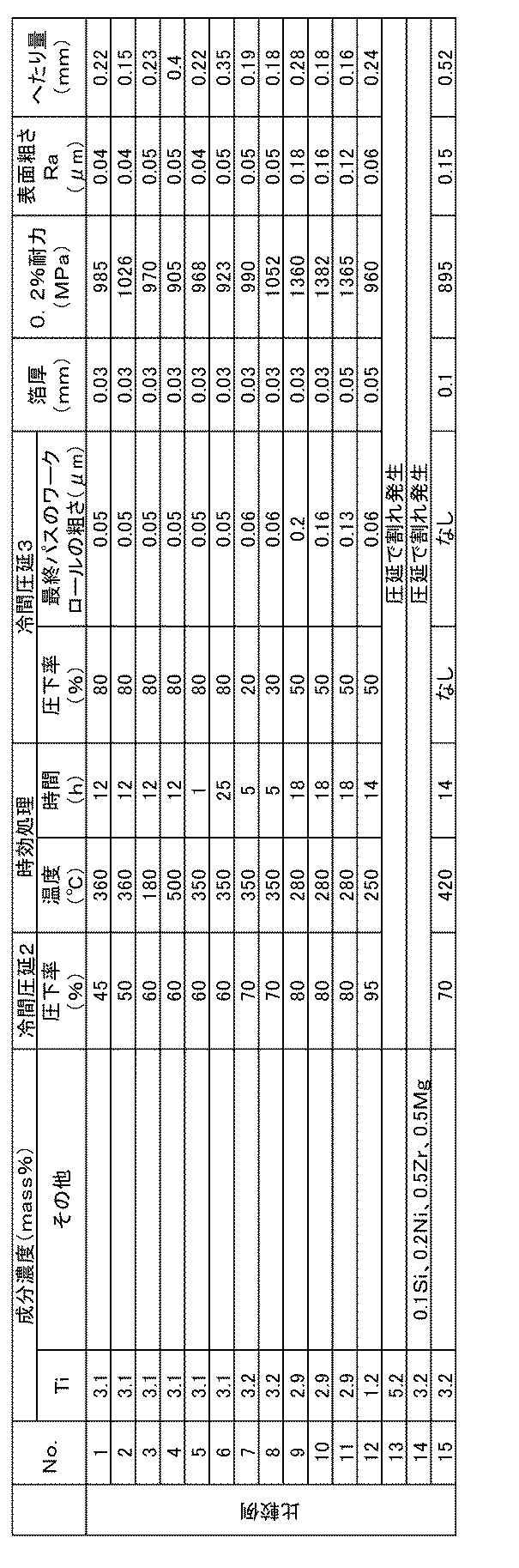
- Table 1 shows the test results. The case where the cold rolling 3 was not performed was described as “none”. Inventive Examples 1 to 32, which are within the specified range of the present invention, have a 0.2% proof stress of 1100 MPa or more and a surface roughness of 0.1 ⁇ m or less. was gotten.
- the surface roughness Ra of Comparative Examples 9 to 11 using a work roll having a roughness exceeding 0.1 ⁇ m in the final pass of the cold rolling 3 exceeded 0.1 ⁇ m, and the amount of sag thereof exceeded 0.1 mm. .
- Comparative Example 12 having a Ti concentration of less than 1.5% by mass was less than 1100 MPa, and the amount of sag exceeded 0.1 mm.
- the 0.2% proof stress of Comparative Example 15 in which the cold rolling 3 was not performed is less than 1100 MPa, the surface roughness exceeds 0.1 mm, and the amount of sag Exceeded 0.1 mm.
Landscapes
- Chemical & Material Sciences (AREA)
- Mechanical Engineering (AREA)
- Organic Chemistry (AREA)
- Metallurgy (AREA)
- Engineering & Computer Science (AREA)
- Materials Engineering (AREA)
- Crystallography & Structural Chemistry (AREA)
- Physics & Mathematics (AREA)
- Thermal Sciences (AREA)
- Conductive Materials (AREA)
- Lens Barrels (AREA)
- Focusing (AREA)
- Automatic Focus Adjustment (AREA)
- Metal Rolling (AREA)
- Non-Insulated Conductors (AREA)
Abstract
オートフォーカスカメラモジュール等の電子機器部品に使用される導電性ばね材として好適な高強度チタン銅箔を提供する。1.5~5.0質量%Tiを含有し、残部が銅及び不可避的不純物からなり、圧延方向に平行な方向での0.2%耐力が1100MPa以上であり、且つ、圧延方向に直角な方向での算術平均粗さ(Ra)が0.1μm以下であるチタン銅箔。
Description
本発明は、オートフォーカスカメラモジュール等の導電性ばね材として好適な、優れた強度を備えたCu-Ti系合金箔に関する。
携帯電話のカメラレンズ部にはオートフォーカスカメラモジュールと呼ばれる電子部品が使用される。携帯電話のカメラのオートフォーカス機能は、オートフォーカスカメラモジュールに使用される材料のばね力でレンズを一定方向に動かす一方、周囲に巻かれたコイルに電流を流すことで発生する電磁力によりレンズを材料のばね力が働く方向とは反対方向へ動かす。このような機構でカメラレンズが駆動しオートフォーカス機能が発揮される(例えば、特許文献1、2)。
したがって、オートフォーカスカメラモジュールに使用される銅合金箔には、電磁力による材料変形に耐えるほどの強度が必要になる。強度が低いと、電磁力による変位に材料が耐えることができず、永久変形(へたり)が発生する。へたりが生じると、一定の電流を流したとき、レンズが所望の位置に移動できずオートフォーカス機能が発揮されない。
オートフォーカスカメラモジュールには、箔厚0.1mm以下で、1100MPa以上の0.2%耐力を有するCu-Ni-Sn系銅合金箔が使用されてきた。しかし、近年のコストダウン要求により、Cu-Ni-Sn系銅合金より比較的材料価格が安いチタン銅箔が使用されるようになり、その需要は増加しつつある。
一方で、チタン銅箔の強度はCu-Ni-Sn系銅合金箔より低く、へたりが生じる問題があるため、その高強度化が望まれている。チタン銅の強度を改善する技術として、特許文献3では最終再結晶焼鈍にて平均結晶粒径を調整し、その後、冷間圧延、時効処理を順次行う方法、特許文献4では固溶化処理後に、冷間圧延、時効処理、冷間圧延を順次行う方法、特許文献5では、熱間圧延及び冷間圧延を行った後、750~1000℃の温度域で5秒~5分間保持する溶体化処理を行い、次いで、圧延率0~50%の冷間圧延、300~550℃の時効処理、及び圧延率0~30%の仕上げ冷間圧延を順次行うことにより板面における{420}のX線回折強度を調整する方法、特許文献6では、第一溶体化処理、中間圧延、最終の溶体化処理、焼鈍、最終の冷間圧延、及び時効処理を所定の条件で順次行うことにより圧延面における{220}のX線回折強度の半価幅を調整する方法がそれぞれ提案されている。
特許文献3~6の実施例及び比較例の中には、1100MPa以上の0.2%耐力をもつチタン銅も幾つか見られる。しかしながら、上記従来技術の場合、箔厚が0.1mm以下と薄いと、材料に荷重を加え変形させた後、荷重を除去すると、へたりが生じ、単に高強度であるのみではオートフォーカスカメラモジュール等の導電性ばね材として使用できないことが分かった。
そこで、本発明はオートフォーカスカメラモジュール等の電子機器部品に使用される導電性ばね材として好適な高強度チタン銅箔を提供することを目的とする。また、本発明はそのようなチタン銅箔の製造方法を提供することを別の目的とする。
本発明者らはチタン銅箔の0.2%耐力とへたりの関係及び表面粗さとへたりの関係を鋭意調査した結果、0.2%耐力が高く、且つ表面粗さが小さいほどへたり量は小さくなることを見出した。本発明は以上の知見を背景として完成したものであり、以下によって特定される。
(1)1.5~5.0質量%Tiを含有し、残部が銅及び不可避的不純物からなり、圧延方向に平行な方向での0.2%耐力が1100MPa以上であり、且つ、圧延方向に直角な方向での算術平均粗さ(Ra)が0.1μm以下であるチタン銅箔。
(2)前記0.2%耐力が1200MPa以上である(1)のチタン銅箔。
(3)箔厚が0.1mm以下である(1)又は(2)のチタン銅箔。
(4)Ag、B、Co、Fe、Mg、Mn、Mo、Ni、P、Si、CrおよびZrのうち1種以上を総量で0~1.0質量%含有する(1)~(3)の何れかのチタン銅箔。
(5)1.5~5.0質量%Tiを含有し、残部が銅及び不可避的不純物からなるインゴットを作製し、このインゴットに対して熱間圧延、冷間圧延を順に行い、次いで、700~1000℃で5秒間~30分間の溶体化処理、圧下率55%以上の冷間圧延、200~450℃で2~20時間の時効処理、圧下率35%以上の最終冷間圧延を順次行い、且つ最終冷間圧延の最終パスを0.1μm以下の算術平均粗さ(Ra)をもつワークロールで圧延することを含む、チタン銅箔の製造方法。
(6)前記インゴットがAg、B、Co、Fe、Mg、Mn、Mo、Ni、P、Si、CrおよびZrのうち1種以上を総量で0~1.0質量%含有する(5)のチタン銅箔の製造方法。
(7)(1)~(4)の何れかのチタン銅箔を備えた伸銅品。
(8)(1)~(4)の何れかのチタン銅箔を備えた電子機器部品。
(9)電子機器部品がオートフォーカスカメラモジュールである(8)の電子機器部品。
(10)レンズと、このレンズを光軸方向の初期位置に弾性付勢するばね部材と、このばね部材の付勢力に抗する電磁力を生起して前記レンズを光軸方向へ駆動可能な電磁駆動手段を備え、前記ばね部材が(1)~(4)の何れか一項に記載のチタン銅箔であることを特徴とするオートフォーカスカメラモジュール。
(2)前記0.2%耐力が1200MPa以上である(1)のチタン銅箔。
(3)箔厚が0.1mm以下である(1)又は(2)のチタン銅箔。
(4)Ag、B、Co、Fe、Mg、Mn、Mo、Ni、P、Si、CrおよびZrのうち1種以上を総量で0~1.0質量%含有する(1)~(3)の何れかのチタン銅箔。
(5)1.5~5.0質量%Tiを含有し、残部が銅及び不可避的不純物からなるインゴットを作製し、このインゴットに対して熱間圧延、冷間圧延を順に行い、次いで、700~1000℃で5秒間~30分間の溶体化処理、圧下率55%以上の冷間圧延、200~450℃で2~20時間の時効処理、圧下率35%以上の最終冷間圧延を順次行い、且つ最終冷間圧延の最終パスを0.1μm以下の算術平均粗さ(Ra)をもつワークロールで圧延することを含む、チタン銅箔の製造方法。
(6)前記インゴットがAg、B、Co、Fe、Mg、Mn、Mo、Ni、P、Si、CrおよびZrのうち1種以上を総量で0~1.0質量%含有する(5)のチタン銅箔の製造方法。
(7)(1)~(4)の何れかのチタン銅箔を備えた伸銅品。
(8)(1)~(4)の何れかのチタン銅箔を備えた電子機器部品。
(9)電子機器部品がオートフォーカスカメラモジュールである(8)の電子機器部品。
(10)レンズと、このレンズを光軸方向の初期位置に弾性付勢するばね部材と、このばね部材の付勢力に抗する電磁力を生起して前記レンズを光軸方向へ駆動可能な電磁駆動手段を備え、前記ばね部材が(1)~(4)の何れか一項に記載のチタン銅箔であることを特徴とするオートフォーカスカメラモジュール。
オートフォーカスカメラモジュール等の電子機器部品に使用される導電性ばね材として好適な高強度Cu-Ti系合金箔が得られる。
(1)Ti濃度
本発明に係るチタン銅箔においては、Ti濃度を1.5~5.0質量%とする。チタン銅は、溶体化処理によりCuマトリックス中へTiを固溶させ、時効処理により微細な析出物を合金中に分散させることにより、強度及び導電率を上昇させる。
Ti濃度が1.5質量%未満になると、析出物の析出が不充分となり所望の強度が得られない。Ti濃度が5.0質量%を超えると、加工性が劣化し、圧延の際に材料が割れやすくなる。強度及び加工性のバランスを考慮すると、好ましいTi濃度は2.9~3.5質量%である。
本発明に係るチタン銅箔においては、Ti濃度を1.5~5.0質量%とする。チタン銅は、溶体化処理によりCuマトリックス中へTiを固溶させ、時効処理により微細な析出物を合金中に分散させることにより、強度及び導電率を上昇させる。
Ti濃度が1.5質量%未満になると、析出物の析出が不充分となり所望の強度が得られない。Ti濃度が5.0質量%を超えると、加工性が劣化し、圧延の際に材料が割れやすくなる。強度及び加工性のバランスを考慮すると、好ましいTi濃度は2.9~3.5質量%である。
(2)その他の添加元素
本発明に係るチタン銅箔においては、Ag、B、Co、Fe、Mg、Mn、Mo、Ni、P、Si、CrおよびZrのうち1種以上を総量で0~1.0質量%含有させることにより、強度を更に向上させることができる。これら元素の合計含有量が0、つまり、これら元素を含まなくても良い。これら元素の合計含有量の上限を1.0質量%としたのは、1.0質量%を超えると、加工性が劣化し、圧延の際に材料が割れやすくなるからである。強度及び加工性のバランスを考慮すると、上記元素の1種以上を総量で0.005~0.5質量%含有させることが好ましい。
本発明に係るチタン銅箔においては、Ag、B、Co、Fe、Mg、Mn、Mo、Ni、P、Si、CrおよびZrのうち1種以上を総量で0~1.0質量%含有させることにより、強度を更に向上させることができる。これら元素の合計含有量が0、つまり、これら元素を含まなくても良い。これら元素の合計含有量の上限を1.0質量%としたのは、1.0質量%を超えると、加工性が劣化し、圧延の際に材料が割れやすくなるからである。強度及び加工性のバランスを考慮すると、上記元素の1種以上を総量で0.005~0.5質量%含有させることが好ましい。
(3)0.2%耐力
オートフォーカスカメラモジュールの導電性ばね材として好適なチタン銅箔に必要な0.2%耐力は1100MPa以上であるところ、本発明に係るチタン銅箔においては、圧延方向に平行な方向での0.2%耐力が1100MPa以上を達成することができる。本発明に係るチタン銅箔の0.2%耐力は好ましい実施形態において1200MPa以上であり、更に好ましい実施形態において1300MPa以上である。
オートフォーカスカメラモジュールの導電性ばね材として好適なチタン銅箔に必要な0.2%耐力は1100MPa以上であるところ、本発明に係るチタン銅箔においては、圧延方向に平行な方向での0.2%耐力が1100MPa以上を達成することができる。本発明に係るチタン銅箔の0.2%耐力は好ましい実施形態において1200MPa以上であり、更に好ましい実施形態において1300MPa以上である。
0.2%耐力の上限値は、本発明が目的とする強度の点からは特に規制されないが、手間及び費用がかかるため、本発明に係るチタン銅箔の0.2%耐力は一般には2000MPa以下であり、典型的には1600MPa以下である。
本発明においては、チタン銅箔の圧延方向に平行な方向での0.2%耐力は、JIS Z2241(金属材料引張試験方法)に準拠して測定する。
(4)表面粗さ(Ra)
一般的に、オートフォーカスカメラモジュール等に使用される導電性ばね材の箔厚は0.1mm以下である。材料に荷重を加えた場合、その応力は材料の箔厚が最も薄い部分に集中する。材料の表面粗さが大きい、つまり材料の箔厚が厚い部分と薄い部分が局所的に存在すると、応力は箔厚が薄い部分に集中し、へたりが生じる。一方で、材料の表面粗さが小さいと、材料に荷重を加えた場合でも応力が特定の場所に集中しにくくなるので、へたりが生じにくくなる。
一般的に、オートフォーカスカメラモジュール等に使用される導電性ばね材の箔厚は0.1mm以下である。材料に荷重を加えた場合、その応力は材料の箔厚が最も薄い部分に集中する。材料の表面粗さが大きい、つまり材料の箔厚が厚い部分と薄い部分が局所的に存在すると、応力は箔厚が薄い部分に集中し、へたりが生じる。一方で、材料の表面粗さが小さいと、材料に荷重を加えた場合でも応力が特定の場所に集中しにくくなるので、へたりが生じにくくなる。
本発明者の検討結果によれば、算術平均粗さ(Ra)を0.1μm以下に制御すると、耐へたり性が有意に向上することが分かった。したがって、本発明に係るチタン銅箔の算術平均粗さ(Ra)は0.1μm以下であり、好ましくは0.08μm以下であり、更に好ましくは0.06μm以下である。表面粗さの下限値は、本発明が目的とする強度の点からは特に規制されない。ただし、極度に小さな算術平均粗さ(Ra)を作り込むことは手間及び費用がかかるため、算術平均粗さ(Ra)は、典型的な実施形態においては0.01μm以上であり、より典型的な実施形態においては0.02μm以上である。
本発明においては、チタン銅箔の圧延方向に直角な方向に沿って、基準長さ300μmの粗さ曲線を採取し、その曲線からJIS B 0601に準拠して算術平均粗さ(Ra)を測定する。
(5)銅箔の厚み
本発明に係るチタン銅箔の一実施形態においては、箔厚が0.1mm以下であり、典型的な実施形態においては箔厚が0.08~0.03mmであり、より典型的な実施形態においては箔厚が0.05~0.03mmである。
本発明に係るチタン銅箔の一実施形態においては、箔厚が0.1mm以下であり、典型的な実施形態においては箔厚が0.08~0.03mmであり、より典型的な実施形態においては箔厚が0.05~0.03mmである。
(6)製造方法
本発明に係るチタン銅箔の製造プロセスでは、まず溶解炉で電気銅、Ti等の原料を溶解し、所望の組成の溶湯を得る。そして、この溶湯をインゴットに鋳造する。チタンの酸化磨耗を防止するため、溶解及び鋳造は真空中又は不活性ガス雰囲気中で行うことが好ましい。その後、熱間圧延、冷間圧延1、溶体化処理、冷間圧延2、時効処理、冷間圧延3をこの順で実施し、所望の厚み及び特性を有する箔に仕上げる。
本発明に係るチタン銅箔の製造プロセスでは、まず溶解炉で電気銅、Ti等の原料を溶解し、所望の組成の溶湯を得る。そして、この溶湯をインゴットに鋳造する。チタンの酸化磨耗を防止するため、溶解及び鋳造は真空中又は不活性ガス雰囲気中で行うことが好ましい。その後、熱間圧延、冷間圧延1、溶体化処理、冷間圧延2、時効処理、冷間圧延3をこの順で実施し、所望の厚み及び特性を有する箔に仕上げる。
熱間圧延及びその後の冷間圧延1の条件はチタン銅の製造で行われている慣例的な条件で行えば足り、特段要求される条件はない。また、溶体化処理についても慣例的な条件で構わないが、例えば700~1000℃で5秒間~30分間の条件で行うことができる。
上述の強度を得るために、冷間圧延2の圧下率を55%以上に規定するのが好ましい。より好ましくは60%以上、更に好ましくは65%以上である。この圧下率が55%未満になると、1100MPa以上の0.2%耐力を得るのは困難になる。圧下率の上限は、本発明が目的とする強度の点からは特に規定されないが、工業的に99.8%を超えることはない。
時効処理の加熱温度は200~450℃、加熱時間2~20時間である。加熱温度が200℃未満又は450℃を超えると1100MPa以上の0.2%耐力を得るのは困難になる。加熱時間が2時間未満又は20時間を越えると1100MPa以上の0.2%耐力を得るのは困難になる。
冷間圧延3の圧下率は35%以上に規定するのが好ましい。より好ましくは40%以上、更に好ましくは45%以上である。この圧下率が35%未満になると、1100MPa以上の0.2%耐力を得るのは困難になる。圧下率の上限は、本発明が目的とする強度の点からは特に規定されないが、工業的に99.8%を超えることはない。
また、上述の表面粗さを得るために、冷間圧延3の最終パスに算術平均粗さ(Ra)が0.1μm以下、好ましくは0.08μm以下、更に好ましくは0.06μm以下のワークロールを使用することが重要である。ワークロールの算術平均粗さが0.1μmを超えると、材料の表面粗さが0.1μmを超えやすい。ただし、ワークロールについて極度に小さな算術平均粗さ(Ra)を作り込むことは手間及び費用がかかるため、算術平均粗さ(Ra)は、典型的な実施形態においては0.01μm以上であり、より典型的な実施形態においては0.02μm以上である。
本発明においては、ワークロールの算術平均粗さ(Ra)を長手方向に対して、つまり、上述した材料の圧延方向に対する直角方向に対応する方向に対して、基準長さ400μmの粗さ曲線を採取し、JIS B 0601に準拠して測定する。
圧延のワークロールの粗さが小さいほど圧延中の材料がスリップし破断や巻きずれといった異常が発生し易くなるため、特別な理由がない限り、圧延に使用されるワークロールの粗さは大きいほど工業的には好ましい。そのため、本発明においても、冷間圧延3の最終パスのみに上述した算術平均粗さ(Ra)が0.1μm以下のワークロールを使用することが好ましい。
チタン銅のように、最終圧延後に熱処理、酸洗やバフ研磨を行う製造方法の場合、その表面品質はバフ研磨に依存するため、圧延に使用されるワークロールの算術平均粗さ(Ra)は0.13μm以上であるのが一般的である。そのため、本発明者の知る限り、上述したような低粗度のワークロールを使用することは従来行われていなかった。
なお、一般的に、時効処理後には、時効時に生成した表面酸化皮膜を除去するために、表面の酸洗や研磨等を行う。本発明でも時効処理後に表面の酸洗や研磨等を行っても良い。また、冷間圧延3の後に低温焼鈍を行っても良く、その後に低温焼鈍時に生成した表面酸化皮膜を除去するために、表面の酸洗や研磨等を行っても良い。ただし、この場合、研磨後の表面粗さが本発明の規定範囲内でなければ本発明の効果は発揮されない。慣例的に実施されている酸化皮膜除去のための研磨では研磨に使用されるバフの粗さが大きいため、本発明で規定するレベルの平滑な表面は得られない。研磨によって本発明で規定する表面粗さを得るためには、バフの粗さを小さくする等の工夫が必要である。
(7)用途
本発明に係るチタン銅箔は、限定的ではないが、スイッチ、コネクタ、ジャック、端子、リレー等の電子機器用部品の材料として好適に使用することができ、とりわけオートフォーカスカメラモジュール等の電子機器部品に使用される導電性ばね材として好適に使用することができる。オートフォーカスカメラモジュールは一実施形態において、レンズと、このレンズを光軸方向の初期位置に弾性付勢するばね部材と、このばね部材の付勢力に抗する電磁力を生起して前記レンズを光軸方向へ駆動可能な電磁駆動手段を備える。電磁駆動手段は例示的には、コの字形円筒形状のヨークと、ヨークの内周壁の内側に収容されるコイルと、コイルを囲繞すると共にヨークの外周壁の内側に収容されるマグネットを備えることができる。
本発明に係るチタン銅箔は、限定的ではないが、スイッチ、コネクタ、ジャック、端子、リレー等の電子機器用部品の材料として好適に使用することができ、とりわけオートフォーカスカメラモジュール等の電子機器部品に使用される導電性ばね材として好適に使用することができる。オートフォーカスカメラモジュールは一実施形態において、レンズと、このレンズを光軸方向の初期位置に弾性付勢するばね部材と、このばね部材の付勢力に抗する電磁力を生起して前記レンズを光軸方向へ駆動可能な電磁駆動手段を備える。電磁駆動手段は例示的には、コの字形円筒形状のヨークと、ヨークの内周壁の内側に収容されるコイルと、コイルを囲繞すると共にヨークの外周壁の内側に収容されるマグネットを備えることができる。
図1は、本発明に係るオートフォーカスカメラモジュールの一例を示す断面図であり、図2は、図1のオートフォーカスカメラモジュールの分解斜視図であり、図3は、図1のオートフォーカスカメラモジュールの動作を示す断面図である。
オートフォーカスカメラモジュール1は、コの字形円筒形状のヨーク2と、ヨーク2の外壁に取付けられるマグネット4と、中央位置にレンズ3を備えるキャリア5と、キャリア5に装着されるコイル6と、ヨーク2が装着されるベース7と、ベース7を支えるフレーム8と、キャリア5を上下で支持する2個のばね部材9a、9bと、これらの上下を覆う2個のキャップ10a、10bとを備えている。2個のばね部材9a、9bは同一品であり、同一の位置関係でキャリア5を上下から挟んで支持すると共に、コイル6への給電経路として機能している。コイル6に電流を印加することによってキャリア5は上方に移動する。尚、本明細書においては、上及び下の文言を適宜、使用するが、図1における上下を指し、上はカメラから被写体に向う位置関係を表わす。
ヨーク2は軟鉄等の磁性体であり、上面部が閉じたコの字形の円筒形状を成し、円筒状の内壁2aと外壁2bを持つ。コの字形の外壁2bの内面には、リング状のマグネット4が装着(接着)される。
キャリア5は底面部を持った円筒形状構造の合成樹脂等による成形品であり、中央位置でレンズを支持し、底面外側上に予め成形されたコイル6が接着されて搭載される。矩形上樹脂成形品のベース7の内周部にヨーク2を嵌合させて組込み、更に樹脂成形品のフレーム8でヨーク2全体を固定する。
ばね部材9a、9bは、いずれも最外周部がそれぞれフレーム8とベース7に挟まれて固定され、内周部120°毎の切欠き溝部がキャリア5に嵌合し、熱カシメ等にて固定される。
ばね部材9bとベース7およびばね部材9aとフレーム8間は接着および熱カシメ等にて固定され更に、キャップ10bはベース7の底面に取付け、キャップ10aはフレーム8の上部に取付けられ、それぞればね部材9bをベース7とキャップ10b間に、ばね部材9aをフレーム8とキャップ10a間に挟み込み固着している。
コイル6の一方のリード線は、キャリア5の内周面に設けた溝内を通って上に伸ばし、ばね部材9aに半田付する。他方のリード線はキャリア5底面に設けた溝内を通って下方に伸ばし、ばね部材9bに半田付する。
ばね部材9a,9bは、本発明に係るチタン銅箔の板バネである。バネ性を持ち、レンズ3を光軸方向の初期位置に弾性付勢する。同時に、コイル6への給電経路としても作用する。ばね部材9a、9bの外周部の一箇所は外側に突出させて、給電端子として機能させている。
円筒状のマグネット4はラジアル(径)方向に磁化されており、コの字形状ヨーク2の内壁2a、上面部及び外壁2bを経路とした磁路を形成し、マグネット4と内壁2a間のギャップには、コイル6が配置される。
ばね部材9a、9bは同一形状であり、図1及び2に示すように同一の位置関係で取付けているので、キャリア5が上方へ移動したときの軸ズレを抑制することができる。コイル6は、巻線後に加圧成形して製作するので、仕上がり外径の精度が向上し、所定の狭いギャップに容易に配置することができる。キャリア5は、最下位置でベース7に突当り、最上位置でヨーク2に突当るので、上下方向に突当て機構を備えることとなり、脱落することを防いでいる。
図3は、コイル6に電流を印加して、オートフォーカス用にレンズ3を備えたキャリア5を上方に移動させた時の断面図を示している。ばね部材9a,9bの給電端子に電源が印加されると、コイル6に電流が流れてキャリア5には上方への電磁力が働く。一方、キャリア5には、連結された2個のばね部材9a,9bの復元力が下方に働く。従って、キャリア5の上方への移動距離は電磁力と復元力が釣合った位置となる。これによって、コイル6に印加する電流量によって、キャリア5の移動量を決定することができる。
上側ばね部材9aはキャリア5の上面を支持し、下側ばね部材9bはキャリア5の下面を支持しているので、復元力はキャリア5の上面及び下面で均等に下方に働くこととなり、レンズ3の軸ズレを小さく抑えることができる。
従って、キャリア5の上方への移動に当って、リブ等によるガイドは必要なく、使っていない。ガイドによる摺動摩擦がないので、キャリア5の移動量は、純粋に電磁力と復元力の釣合いで支配されることとなり、円滑で精度良いレンズ3の移動を実現している。これによってレンズブレの少ないオートフォーカスを達成している。
なお、マグネット4は円筒形状として説明したが、これに拘わるものでなく、3乃至4分割してラジアル方向に磁化し、これをヨーク2の外壁2bの内面に貼付けて固着しても良い。
以下に本発明の実施例を比較例と共に示すが、これらの実施例は本発明及びその利点をよりよく理解するために提供するものであり、発明が限定されることを意図するものではない。
表1に示す合金成分を含有し残部が銅及び不可避的不純物からなる合金を実験材料とし、合金成分及び製造条件が0.2%耐力及びへたりに及ぼす影響を調査した。
真空溶解炉にて電気銅2.5kgを溶解し、表1に記載の合金組成が得られるよう合金元素を添加した。この溶湯を鋳鉄製の鋳型に鋳込み、厚さ30mm、幅60mm、長さ120mmのインゴットを製造した。このインゴットを、次の工程順で加工し、表1に記載の所定の箔厚をもつ製品試料を作製した。
真空溶解炉にて電気銅2.5kgを溶解し、表1に記載の合金組成が得られるよう合金元素を添加した。この溶湯を鋳鉄製の鋳型に鋳込み、厚さ30mm、幅60mm、長さ120mmのインゴットを製造した。このインゴットを、次の工程順で加工し、表1に記載の所定の箔厚をもつ製品試料を作製した。
(1)熱間圧延:インゴットを950℃で3時間加熱し、厚さ10mmまで圧延した。
(2)研削:熱間圧延で生成した酸化スケールをグラインダーで除去した。研削後の厚みは9mmであった。
(3)冷間圧延1:圧下率に応じて所定の厚みまで圧延した。
(4)溶体化処理:800℃に昇温した電気炉に試料を装入し、5分間保持した後、試料を水槽に入れて急冷却した。
(5)冷間圧延2:圧下率に応じて所定の厚みまで圧延した。
(6)時効処理:表1に示す温度及び時間、Ar雰囲気中で加熱した。該温度は時効後の引張強さが最大になるように選択した。
(7)酸洗・バフ研磨:時効処理で生成した酸化スケールを除去するために、15vol.%硫酸-1.5vol.%過酸化水溶液中でバフ研磨を行った。
(8)冷間圧延3:表1に示す箔厚まで圧延した。更に圧延の最終パスは表1に示す粗さのワークロールを使用した。
(2)研削:熱間圧延で生成した酸化スケールをグラインダーで除去した。研削後の厚みは9mmであった。
(3)冷間圧延1:圧下率に応じて所定の厚みまで圧延した。
(4)溶体化処理:800℃に昇温した電気炉に試料を装入し、5分間保持した後、試料を水槽に入れて急冷却した。
(5)冷間圧延2:圧下率に応じて所定の厚みまで圧延した。
(6)時効処理:表1に示す温度及び時間、Ar雰囲気中で加熱した。該温度は時効後の引張強さが最大になるように選択した。
(7)酸洗・バフ研磨:時効処理で生成した酸化スケールを除去するために、15vol.%硫酸-1.5vol.%過酸化水溶液中でバフ研磨を行った。
(8)冷間圧延3:表1に示す箔厚まで圧延した。更に圧延の最終パスは表1に示す粗さのワークロールを使用した。
作製した製品試料について、次の評価を行った。
(イ)0.2%耐力
引張試験機を用いて上述した測定方法に従い圧延方向と平行な方向の0.2%耐力を測定した。
(ロ)表面粗さ
箔表面の算術平均粗さ(Ra)は、Lasertec社製コンフォーカル顕微鏡HD-100により、上述した測定方法で求めた。測定は圧延方向に対して直角に行った。
(ハ)へたり
幅10mmの短冊試料を長手方向が圧延平行方向となるように採取し、図4のように、試料の片端を固定し、この固定端から距離Lの位置に、先端をナイフエッジに加工したポンチを1mm/分の移動速度で押し当て、試料に距離dのたわみを与えた後、ポンチを初期の位置に戻し除荷した。除荷後、へたり量δを求めた。
試験条件は試料の箔厚が0.05mm以下の場合、L=3mm、d=2mmであり、箔厚が0.05mmより厚い場合、L=5mm、d=4mmである。また、へたり量は0.01mmの分解能で測定し、へたりが検出されなかった場合は<0.01mmと表記している。
(イ)0.2%耐力
引張試験機を用いて上述した測定方法に従い圧延方向と平行な方向の0.2%耐力を測定した。
(ロ)表面粗さ
箔表面の算術平均粗さ(Ra)は、Lasertec社製コンフォーカル顕微鏡HD-100により、上述した測定方法で求めた。測定は圧延方向に対して直角に行った。
(ハ)へたり
幅10mmの短冊試料を長手方向が圧延平行方向となるように採取し、図4のように、試料の片端を固定し、この固定端から距離Lの位置に、先端をナイフエッジに加工したポンチを1mm/分の移動速度で押し当て、試料に距離dのたわみを与えた後、ポンチを初期の位置に戻し除荷した。除荷後、へたり量δを求めた。
試験条件は試料の箔厚が0.05mm以下の場合、L=3mm、d=2mmであり、箔厚が0.05mmより厚い場合、L=5mm、d=4mmである。また、へたり量は0.01mmの分解能で測定し、へたりが検出されなかった場合は<0.01mmと表記している。
ワークロールの算術平均粗さ(Ra)は、接触式粗さ測定機を用いて、上述した測定方法で求めた。
表1に試験結果を示す。冷間圧延3を実施しなかった場合については「なし」と記載した。
本発明の規定範囲内である発明例1~32は、0.2%耐力が1100MPa以上、表面粗さ0.1μm以下が得られ、それらのへたり量は0.1mm以下と小さく良好な特性が得られた。
冷間圧延2の圧下率が55%未満である比較例1及び2、時効処理の温度が200~450℃の範囲外である比較例3及び4、時効処理の時間が2~20時間の範囲外である比較例5及び6、冷間圧延3の圧下率が35%未満である比較例7及び8は、0.2%耐力が1100MPa未満となり、それらのへたり量は0.1mmを越えた。
冷間圧延3の最終パスに粗さ0.1μmを越えたワークロールを使用した比較例9~11の表面粗さRaは0.1μmを超え、それらのへたり量は0.1mmを超えた。
Ti濃度が1.5質量%未満である比較例12の0.2%耐力は1100MPa未満となり、そのへたり量は0.1mmを超えた。一方、Ti濃度が5.0質量%を越えた比較例13、Ti以外の添加元素の総量が1.0質量%を越えた比較例14は圧延中に割れが発生し評価できなかった。
また、時効処理後に酸洗及びバフ研磨を行った後、冷間圧延3を行わなかった比較例15の0.2%耐力は1100MPa未満、表面粗さは0.1mmを超え、そのへたり量は0.1mmを超えた。
本発明の規定範囲内である発明例1~32は、0.2%耐力が1100MPa以上、表面粗さ0.1μm以下が得られ、それらのへたり量は0.1mm以下と小さく良好な特性が得られた。
冷間圧延2の圧下率が55%未満である比較例1及び2、時効処理の温度が200~450℃の範囲外である比較例3及び4、時効処理の時間が2~20時間の範囲外である比較例5及び6、冷間圧延3の圧下率が35%未満である比較例7及び8は、0.2%耐力が1100MPa未満となり、それらのへたり量は0.1mmを越えた。
冷間圧延3の最終パスに粗さ0.1μmを越えたワークロールを使用した比較例9~11の表面粗さRaは0.1μmを超え、それらのへたり量は0.1mmを超えた。
Ti濃度が1.5質量%未満である比較例12の0.2%耐力は1100MPa未満となり、そのへたり量は0.1mmを超えた。一方、Ti濃度が5.0質量%を越えた比較例13、Ti以外の添加元素の総量が1.0質量%を越えた比較例14は圧延中に割れが発生し評価できなかった。
また、時効処理後に酸洗及びバフ研磨を行った後、冷間圧延3を行わなかった比較例15の0.2%耐力は1100MPa未満、表面粗さは0.1mmを超え、そのへたり量は0.1mmを超えた。

1 オートフォーカスカメラモジュール
2 ヨーク
3 レンズ
4 マグネット
5 キャリア
6 コイル
7 ベース
8 フレーム
9a 上側のばね部材
9b 下側のばね部材
10a,10b キャップ
2 ヨーク
3 レンズ
4 マグネット
5 キャリア
6 コイル
7 ベース
8 フレーム
9a 上側のばね部材
9b 下側のばね部材
10a,10b キャップ
Claims (8)
- 1.5~5.0質量%Tiを含有し、Ag、B、Co、Fe、Mg、Mn、Mo、Ni、P、Si、CrおよびZrのうち1種以上を総量で0~1.0質量%含有し、残部が銅及び不可避的不純物からなり、圧延方向に平行な方向での0.2%耐力が1100MPa以上であり、且つ、圧延方向に直角な方向での算術平均粗さ(Ra)が0.1μm以下であるチタン銅箔。
- 前記0.2%耐力が1200MPa以上である請求項1に記載のチタン銅箔。
- 箔厚が0.1mm以下である請求項1又は2に記載のチタン銅箔。
- 1.5~5.0質量%Tiを含有し、Ag、B、Co、Fe、Mg、Mn、Mo、Ni、P、Si、CrおよびZrのうち1種以上を総量で0~1.0質量%含有し、残部が銅及び不可避的不純物からなるインゴットを作製し、このインゴットに対して熱間圧延、冷間圧延を順に行い、次いで、700~1000℃で5秒間~30分間の溶体化処理、圧下率55%以上の冷間圧延、200~450℃で2~20時間の時効処理、圧下率35%以上の最終冷間圧延を順次行い、且つ最終冷間圧延の最終パスを0.1μm以下の算術平均粗さ(Ra)をもつワークロールで圧延することを含む、チタン銅箔の製造方法。
- 請求項1~3の何れか一項に記載のチタン銅箔を備えた伸銅品。
- 請求項1~3の何れか一項に記載のチタン銅箔を備えた電子機器部品。
- 電子機器部品がオートフォーカスカメラモジュールである請求項6に記載の電子機器部品。
- レンズと、このレンズを光軸方向の初期位置に弾性付勢するばね部材と、このばね部材の付勢力に抗する電磁力を生起して前記レンズを光軸方向へ駆動可能な電磁駆動手段を備え、前記ばね部材が請求項1~3の何れか一項に記載のチタン銅箔であることを特徴とするオートフォーカスカメラモジュール。
Priority Applications (2)
| Application Number | Priority Date | Filing Date | Title |
|---|---|---|---|
| KR1020157004286A KR101704941B1 (ko) | 2012-07-19 | 2013-07-03 | 고강도 티탄 동박 및 그 제조 방법 |
| CN201380038387.3A CN104487600A (zh) | 2012-07-19 | 2013-07-03 | 高强度钛铜箔及其制备方法 |
Applications Claiming Priority (4)
| Application Number | Priority Date | Filing Date | Title |
|---|---|---|---|
| JP2012-160798 | 2012-07-19 | ||
| JP2012160798 | 2012-07-19 | ||
| JP2012-232972 | 2012-10-22 | ||
| JP2012232972A JP5723849B2 (ja) | 2012-07-19 | 2012-10-22 | 高強度チタン銅箔及びその製造方法 |
Publications (1)
| Publication Number | Publication Date |
|---|---|
| WO2014013876A1 true WO2014013876A1 (ja) | 2014-01-23 |
Family
ID=49948706
Family Applications (1)
| Application Number | Title | Priority Date | Filing Date |
|---|---|---|---|
| PCT/JP2013/068263 Ceased WO2014013876A1 (ja) | 2012-07-19 | 2013-07-03 | 高強度チタン銅箔及びその製造方法 |
Country Status (5)
| Country | Link |
|---|---|
| JP (1) | JP5723849B2 (ja) |
| KR (1) | KR101704941B1 (ja) |
| CN (2) | CN104487600A (ja) |
| TW (1) | TWI479037B (ja) |
| WO (1) | WO2014013876A1 (ja) |
Cited By (3)
| Publication number | Priority date | Publication date | Assignee | Title |
|---|---|---|---|---|
| JP2017179572A (ja) * | 2016-03-31 | 2017-10-05 | Jx金属株式会社 | めっき層を有するチタン銅箔 |
| EP3845675A4 (en) * | 2018-08-30 | 2021-12-22 | JX Nippon Mining & Metals Corporation | TITANIUM COPPER PLATE, PRESSED PRODUCT AND METHOD FOR MANUFACTURING PRESSED PRODUCTS |
| WO2025062852A1 (ja) * | 2023-09-21 | 2025-03-27 | Jx金属株式会社 | チタン銅箔、チタン銅条、電子部品及び、チタン銅箔の製造方法 |
Families Citing this family (20)
| Publication number | Priority date | Publication date | Assignee | Title |
|---|---|---|---|---|
| JP6080820B2 (ja) | 2014-08-29 | 2017-02-15 | Jx金属株式会社 | 高強度チタン銅箔及びその製造方法 |
| JP6073268B2 (ja) * | 2014-08-29 | 2017-02-01 | Jx金属株式会社 | 高強度チタン銅箔及びその製造方法 |
| JP6228941B2 (ja) | 2015-01-09 | 2017-11-08 | Jx金属株式会社 | めっき層を有するチタン銅 |
| CN106994464A (zh) * | 2016-01-26 | 2017-08-01 | 中国科学院金属研究所 | 一种纯镁或镁合金箔材的冷轧生产工艺 |
| JP6796943B2 (ja) * | 2016-03-31 | 2020-12-09 | Jx金属株式会社 | めっき層を有するチタン銅箔 |
| JP6662685B2 (ja) * | 2016-03-31 | 2020-03-11 | Jx金属株式会社 | めっき層を有するチタン銅箔 |
| JP6391621B2 (ja) * | 2016-03-31 | 2018-09-19 | Jx金属株式会社 | チタン銅箔、伸銅品、電子機器部品およびオートフォーカスカメラモジュール |
| JP2017179573A (ja) * | 2016-03-31 | 2017-10-05 | Jx金属株式会社 | めっき層を有するチタン銅箔 |
| JP6618410B2 (ja) * | 2016-03-31 | 2019-12-11 | Jx金属株式会社 | チタン銅箔、伸銅品、電子機器部品およびオートフォーカスカメラモジュール |
| JP6703878B2 (ja) * | 2016-03-31 | 2020-06-03 | Jx金属株式会社 | チタン銅箔および、その製造方法 |
| JP6609589B2 (ja) | 2017-03-30 | 2019-11-20 | Jx金属株式会社 | 層状組織を有する高強度チタン銅条および箔 |
| JP6609590B2 (ja) | 2017-03-30 | 2019-11-20 | Jx金属株式会社 | 層状組織を有する高強度チタン銅条および箔 |
| TWI873415B (zh) * | 2017-08-10 | 2025-02-21 | 日商田中貴金屬工業股份有限公司 | 高強度與高導電性的銅合金板材及其製造方法 |
| JP2019065362A (ja) * | 2017-10-03 | 2019-04-25 | Jx金属株式会社 | Cu−Ni−Sn系銅合金箔、伸銅品、電子機器部品およびオートフォーカスカメラモジュール |
| JP2019065361A (ja) * | 2017-10-03 | 2019-04-25 | Jx金属株式会社 | Cu−Ni−Sn系銅合金箔、伸銅品、電子機器部品およびオートフォーカスカメラモジュール |
| JP6650987B1 (ja) | 2018-11-09 | 2020-02-19 | Jx金属株式会社 | チタン銅箔、伸銅品、電子機器部品及びオートフォーカスカメラモジュール |
| JP6745859B2 (ja) | 2018-11-09 | 2020-08-26 | Jx金属株式会社 | チタン銅箔、伸銅品、電子機器部品及びオートフォーカスカメラモジュール |
| JP6953465B2 (ja) * | 2019-03-27 | 2021-10-27 | Jx金属株式会社 | チタン銅箔及びチタン銅箔の製造方法 |
| JP2019199650A (ja) * | 2019-07-10 | 2019-11-21 | Jx金属株式会社 | めっき層を有するチタン銅箔 |
| CN111101016B (zh) * | 2020-02-26 | 2021-01-19 | 宁波博威合金材料股份有限公司 | 一种时效强化型钛铜合金及其制备方法 |
Citations (8)
| Publication number | Priority date | Publication date | Assignee | Title |
|---|---|---|---|---|
| JPH06264202A (ja) * | 1993-03-09 | 1994-09-20 | Nikko Kinzoku Kk | 高強度銅合金の製造方法 |
| JP2005187885A (ja) * | 2003-12-25 | 2005-07-14 | Nikko Metal Manufacturing Co Ltd | 疲労特性に優れたチタン銅条 |
| JP2007107036A (ja) * | 2005-10-12 | 2007-04-26 | Nikko Kinzoku Kk | 屈曲用圧延銅合金箔 |
| JP2009301794A (ja) * | 2008-06-11 | 2009-12-24 | Canon Inc | 電子機器 |
| JP2010197718A (ja) * | 2009-02-25 | 2010-09-09 | Olympus Corp | 駆動モジュール |
| JP2010261066A (ja) * | 2009-04-30 | 2010-11-18 | Jx Nippon Mining & Metals Corp | 電子部品用チタン銅の製造方法 |
| JP2011136357A (ja) * | 2009-12-28 | 2011-07-14 | Jx Nippon Mining & Metals Corp | 銅箔及びそれを用いた銅張積層板 |
| JP2012097308A (ja) * | 2010-10-29 | 2012-05-24 | Jx Nippon Mining & Metals Corp | 銅合金、伸銅品、電子部品及びコネクタ |
Family Cites Families (11)
| Publication number | Priority date | Publication date | Assignee | Title |
|---|---|---|---|---|
| JPH04259828A (ja) | 1991-02-15 | 1992-09-16 | Nec Gumma Ltd | 光パワーメータ |
| JP4001491B2 (ja) | 2001-02-20 | 2007-10-31 | 日鉱金属株式会社 | 高強度チタン銅合金及びその製造法並びにそれを用いた端子・コネクター |
| JP4259828B2 (ja) * | 2002-08-30 | 2009-04-30 | Dowaメタニクス株式会社 | 高強度銅合金の製造方法 |
| JP4273247B2 (ja) | 2003-03-13 | 2009-06-03 | シコー株式会社 | レンズ駆動装置 |
| JP4091593B2 (ja) * | 2004-11-05 | 2008-05-28 | Smk株式会社 | オートフォーカス機能付カメラモジュールとモジュール用コネクタの接続構造 |
| JP2009115895A (ja) | 2007-11-02 | 2009-05-28 | Alps Electric Co Ltd | カメラモジュール |
| JP5208555B2 (ja) * | 2008-03-31 | 2013-06-12 | Jx日鉱日石金属株式会社 | 電子部品用チタン銅 |
| JP4563480B2 (ja) * | 2008-11-28 | 2010-10-13 | Dowaメタルテック株式会社 | 銅合金板材およびその製造方法 |
| JP5493986B2 (ja) * | 2009-04-27 | 2014-05-14 | Jfeスチール株式会社 | 加工性に優れた高強度鋼板および高強度溶融亜鉛めっき鋼板並びにそれらの製造方法 |
| JP4761586B1 (ja) * | 2010-03-25 | 2011-08-31 | Jx日鉱日石金属株式会社 | 高強度チタン銅板及びその製造方法 |
| JP5319590B2 (ja) | 2010-03-30 | 2013-10-16 | Jx日鉱日石金属株式会社 | 銅合金、銅合金の製造方法及び電子部品の製造方法 |
-
2012
- 2012-10-22 JP JP2012232972A patent/JP5723849B2/ja active Active
-
2013
- 2013-07-02 TW TW102123574A patent/TWI479037B/zh active
- 2013-07-03 WO PCT/JP2013/068263 patent/WO2014013876A1/ja not_active Ceased
- 2013-07-03 CN CN201380038387.3A patent/CN104487600A/zh active Pending
- 2013-07-03 CN CN201910247167.0A patent/CN110042269A/zh active Pending
- 2013-07-03 KR KR1020157004286A patent/KR101704941B1/ko active Active
Patent Citations (8)
| Publication number | Priority date | Publication date | Assignee | Title |
|---|---|---|---|---|
| JPH06264202A (ja) * | 1993-03-09 | 1994-09-20 | Nikko Kinzoku Kk | 高強度銅合金の製造方法 |
| JP2005187885A (ja) * | 2003-12-25 | 2005-07-14 | Nikko Metal Manufacturing Co Ltd | 疲労特性に優れたチタン銅条 |
| JP2007107036A (ja) * | 2005-10-12 | 2007-04-26 | Nikko Kinzoku Kk | 屈曲用圧延銅合金箔 |
| JP2009301794A (ja) * | 2008-06-11 | 2009-12-24 | Canon Inc | 電子機器 |
| JP2010197718A (ja) * | 2009-02-25 | 2010-09-09 | Olympus Corp | 駆動モジュール |
| JP2010261066A (ja) * | 2009-04-30 | 2010-11-18 | Jx Nippon Mining & Metals Corp | 電子部品用チタン銅の製造方法 |
| JP2011136357A (ja) * | 2009-12-28 | 2011-07-14 | Jx Nippon Mining & Metals Corp | 銅箔及びそれを用いた銅張積層板 |
| JP2012097308A (ja) * | 2010-10-29 | 2012-05-24 | Jx Nippon Mining & Metals Corp | 銅合金、伸銅品、電子部品及びコネクタ |
Cited By (3)
| Publication number | Priority date | Publication date | Assignee | Title |
|---|---|---|---|---|
| JP2017179572A (ja) * | 2016-03-31 | 2017-10-05 | Jx金属株式会社 | めっき層を有するチタン銅箔 |
| EP3845675A4 (en) * | 2018-08-30 | 2021-12-22 | JX Nippon Mining & Metals Corporation | TITANIUM COPPER PLATE, PRESSED PRODUCT AND METHOD FOR MANUFACTURING PRESSED PRODUCTS |
| WO2025062852A1 (ja) * | 2023-09-21 | 2025-03-27 | Jx金属株式会社 | チタン銅箔、チタン銅条、電子部品及び、チタン銅箔の製造方法 |
Also Published As
| Publication number | Publication date |
|---|---|
| TW201410886A (zh) | 2014-03-16 |
| CN104487600A (zh) | 2015-04-01 |
| TWI479037B (zh) | 2015-04-01 |
| JP5723849B2 (ja) | 2015-05-27 |
| KR101704941B1 (ko) | 2017-02-08 |
| JP2014037613A (ja) | 2014-02-27 |
| CN110042269A (zh) | 2019-07-23 |
| KR20150034275A (ko) | 2015-04-02 |
Similar Documents
| Publication | Publication Date | Title |
|---|---|---|
| JP5723849B2 (ja) | 高強度チタン銅箔及びその製造方法 | |
| JP5526212B2 (ja) | 高強度チタン銅箔及びその製造方法 | |
| JP6080820B2 (ja) | 高強度チタン銅箔及びその製造方法 | |
| JP6073268B2 (ja) | 高強度チタン銅箔及びその製造方法 | |
| JP6391621B2 (ja) | チタン銅箔、伸銅品、電子機器部品およびオートフォーカスカメラモジュール | |
| US11174534B2 (en) | High strength titanium copper strip and foil having layered structure | |
| US12000029B2 (en) | Titanium copper foil, extended copper article, electronic device component, and auto-focus camera module | |
| EP3604572B1 (en) | High strength titanium copper having layered structure and use thereof | |
| EP3878988A1 (en) | Titanium copper foil, extended copper article, electronic device component, and auto-focus camera module |
Legal Events
| Date | Code | Title | Description |
|---|---|---|---|
| 121 | Ep: the epo has been informed by wipo that ep was designated in this application |
Ref document number: 13820324 Country of ref document: EP Kind code of ref document: A1 |
|
| NENP | Non-entry into the national phase |
Ref country code: DE |
|
| ENP | Entry into the national phase |
Ref document number: 20157004286 Country of ref document: KR Kind code of ref document: A |
|
| 122 | Ep: pct application non-entry in european phase |
Ref document number: 13820324 Country of ref document: EP Kind code of ref document: A1 |